EP3893025B1 - Gnss receiver and gnss device - Google Patents
Gnss receiver and gnss device Download PDFInfo
- Publication number
- EP3893025B1 EP3893025B1 EP20757821.2A EP20757821A EP3893025B1 EP 3893025 B1 EP3893025 B1 EP 3893025B1 EP 20757821 A EP20757821 A EP 20757821A EP 3893025 B1 EP3893025 B1 EP 3893025B1
- Authority
- EP
- European Patent Office
- Prior art keywords
- gnss receiver
- processor
- gnss
- lithium battery
- operating state
- Prior art date
- Legal status (The legal status is an assumption and is not a legal conclusion. Google has not performed a legal analysis and makes no representation as to the accuracy of the status listed.)
- Active
Links
Images



Classifications
-
- G—PHYSICS
- G01—MEASURING; TESTING
- G01S—RADIO DIRECTION-FINDING; RADIO NAVIGATION; DETERMINING DISTANCE OR VELOCITY BY USE OF RADIO WAVES; LOCATING OR PRESENCE-DETECTING BY USE OF THE REFLECTION OR RERADIATION OF RADIO WAVES; ANALOGOUS ARRANGEMENTS USING OTHER WAVES
- G01S19/00—Satellite radio beacon positioning systems; Determining position, velocity or attitude using signals transmitted by such systems
- G01S19/01—Satellite radio beacon positioning systems transmitting time-stamped messages, e.g. GPS [Global Positioning System], GLONASS [Global Orbiting Navigation Satellite System] or GALILEO
- G01S19/13—Receivers
-
- G—PHYSICS
- G01—MEASURING; TESTING
- G01S—RADIO DIRECTION-FINDING; RADIO NAVIGATION; DETERMINING DISTANCE OR VELOCITY BY USE OF RADIO WAVES; LOCATING OR PRESENCE-DETECTING BY USE OF THE REFLECTION OR RERADIATION OF RADIO WAVES; ANALOGOUS ARRANGEMENTS USING OTHER WAVES
- G01S19/00—Satellite radio beacon positioning systems; Determining position, velocity or attitude using signals transmitted by such systems
- G01S19/01—Satellite radio beacon positioning systems transmitting time-stamped messages, e.g. GPS [Global Positioning System], GLONASS [Global Orbiting Navigation Satellite System] or GALILEO
- G01S19/13—Receivers
- G01S19/34—Power consumption
-
- G—PHYSICS
- G01—MEASURING; TESTING
- G01S—RADIO DIRECTION-FINDING; RADIO NAVIGATION; DETERMINING DISTANCE OR VELOCITY BY USE OF RADIO WAVES; LOCATING OR PRESENCE-DETECTING BY USE OF THE REFLECTION OR RERADIATION OF RADIO WAVES; ANALOGOUS ARRANGEMENTS USING OTHER WAVES
- G01S19/00—Satellite radio beacon positioning systems; Determining position, velocity or attitude using signals transmitted by such systems
- G01S19/01—Satellite radio beacon positioning systems transmitting time-stamped messages, e.g. GPS [Global Positioning System], GLONASS [Global Orbiting Navigation Satellite System] or GALILEO
- G01S19/13—Receivers
- G01S19/14—Receivers specially adapted for specific applications
-
- G—PHYSICS
- G01—MEASURING; TESTING
- G01S—RADIO DIRECTION-FINDING; RADIO NAVIGATION; DETERMINING DISTANCE OR VELOCITY BY USE OF RADIO WAVES; LOCATING OR PRESENCE-DETECTING BY USE OF THE REFLECTION OR RERADIATION OF RADIO WAVES; ANALOGOUS ARRANGEMENTS USING OTHER WAVES
- G01S5/00—Position-fixing by co-ordinating two or more direction or position line determinations; Position-fixing by co-ordinating two or more distance determinations
- G01S5/0009—Transmission of position information to remote stations
- G01S5/0018—Transmission from mobile station to base station
- G01S5/0027—Transmission from mobile station to base station of actual mobile position, i.e. position determined on mobile
Definitions
- the present application relates to the technical field of a global satellite system, for example, a GNSS receiver and a GNSS device.
- GNSS global navigation satellite system
- some sections with frequent geological disasters such as a mountain slope
- GNSS detection systems can be disposed at intervals to monitor whether a landform of the mountain slope has changed, thereby giving early warning to the upcoming a mountain landslide and other disasters.
- the GNSS receiver is usually in a normally open operating state to avoid data missing.
- the existing problem is that it may take a long time for the landform of the mountain slope to change slightly; in this way, before the landform of the mountain slope changes, the GNSS receiver is in an operating state for a long time, and a battery storing sufficient electric energy is required to supply power to the GNSS receiver, so that the consumption energy of the overall device is high, the battery volume is large, and the off-field installation is difficult.
- US 2018041965 A1 discloses a method of scheduling wakeup events, method of operating a mobile transceiver, and devices configured for same are provided.
- a method of scheduling wakeup events for a mobile transceiver comprising: obtaining a first GNSS data set comprising a plurality of GNSS coordinates, the first GNSS data set defining a route; applying a curve simplification algorithm to generate a second GNSS data set comprising a plurality of GNSS coordinates, wherein the second GNSS data set is a subset of the first GNSS data set; defining one or more alarms as wakeup events to activate the satellite receiver from a low power mode based on the plurality of GNSS coordinates of the second GNSS data, wherein the one or more wakeup events are each defined by an alarm; and applying the one or more alarms.
- US 2011071759 A1 discloses a system and method for controlling a navigation receiver is disclosed.
- a current position is determined using the navigation receiver and then the navigation receiver is placed in a power-save mode.
- the current position is updated using information from position sensors.
- the navigation receiver is temporarily placed in an active mode at intervals to determine an intermediate position.
- the current position is also updated using the intermediate position.
- the navigation receiver may be a GNSS receiver, a cellular receiver, a WiFi receiver, or another position-fixing device.
- the position sensors may be accelerometers, gyroscopes, electronic compasses or mapping data.
- a power-save controller controls the power-save or active mode of the navigation receiver.
- a sensor conditioning circuit pre-processes the data from the position sensors before providing the data to the power-save controller.
- an RF subsystem and/or a baseband subsystem of the navigation receiver may be turned off.
- a GNSS receiver and a GNSS device are set out in the appended set of claims to achieve low power consumption, simple installation and short construction time of the overall device.
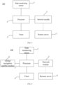
- FIG. 1 is a block schematic diagram of a GNSS receiver according to an embodiment of the present application.
- a global navigation satellite system (GNSS) receiver 100 includes a state monitoring sensor 1 and a processor 2.
- the state monitoring sensor 1 is configured to monitor a state of the GNSS receiver 100, and generate a first triggering signal according to the state of the GNSS receiver 100.
- the processor 2 is configured to switch from a resting operating state to a wake-up operating state according to the first triggering signal, and transmit position information about the GNSS receiver 100 to a remote server 3 at a preset frequency.
- a position state of the GNSS receiver 100 may timely reflect a change of landform or terrain in which the GNSS receiver 100 is installed.
- the position state of the GNSS receiver 100 will change accordingly.
- the GNSS receiver 100 is installed in a certain mountain, and in a case where a mountain landslide occurs, the position state of the GNSS receiver 100 is shifted from an initial state, that is, a current position of the GNSS receiver 100 is changed from an initial position. Therefore, in a case where a state of the GNSS receiver 100 changes, the change of the landform or terrain may be reflected, where whether or not the position state of the GNSS receiver 100 is changed is defined as the state of the GNSS receiver 100.
- the state monitoring sensor 1 is configured to monitor whether or not the position state of the GNSS receiver 100 is changed. In a case where the state monitoring sensor 1 monitors that the position state of the GNSS receiver 100 is changed, the state monitoring sensor 1 judges that the landform or terrain is changed, and generates the first triggering signal. At the moment, the processor 2 switches from the resting operating state to the wake-up operating state according to the first triggering signal, and transmits the position information about the GNSS receiver 100 to the remote server 3 at the preset frequency to remind a technician of the change of the landform or terrain of the current position where the GNSS receiver 100 is located. In this embodiment, in a case where the landform or terrain is not changed, a situation that the processor 2 is still in the wake-up operating state and transmits the position information about the GNSS receiver 100 to the remote server 3 to waste electric energy may be avoided.
- the state monitoring sensor 1 is an acceleration sensor, where the acceleration sensor is configured to monitor an acceleration of the GNSS receiver 100, and generate the first triggering signal when the acceleration of the GNSS receiver 100 is greater than a first preset value.
- the acceleration of the GNSS receiver 100 is greater than the first preset value
- the position state of the GNSS receiver 100 is considered to be changed, where the first preset value may be in a range from 50 mg to 200 mg. That is, in a case where the acceleration sensor monitors that the acceleration of the GNSS receiver 100 is greater than the first preset value, the acceleration sensor generates the first triggering signal to trigger the processor 2 to switch from the resting operating state to the wake-up operating state.
- the state monitoring sensor 1 may be the acceleration sensor, and the acceleration sensor may be selected as an ADXL362 model acceleration sensor.
- the processor 2 is further configured to switch from the wake-up operating state to the resting operating state in response to transmitting the position information about the GNSS receiver 100 continuously for N times to the remote server 3, where N is a positive integer.
- the processor 2 transmits the position information about the GNSS receiver 100 to the remote server at the preset frequency, where the preset frequency may be determined according to the actual situation.
- the preset frequency is 1 Hz
- the position information about the GNSS receiver 100 transmitted by the processor 2 to the remote server continuously for 5 to 10 minutes is the same or nearly the same (the difference between the two is less than a certain threshold value, that is, the difference is almost negligible)
- the position state of the GNSS receiver 100 may be judged to remain almost unchanged, and the processor 2 further switches from the wake-up operating state to the resting operating state, where N may be selected as 400.
- the processor 2 After the GNSS receiver 100 is installed and debugged, the processor 2 is in the resting state by default. In a case where the state monitoring sensor 1 monitors a change in the state of the GNSS receiver 100, the state monitoring sensor 1 generates the first triggering signal and the first triggering signal triggers the processor 2 to switch from the resting operating state to the wakeup operating state; the processor 2 transmits the position information about the GNSS receiver 100 to the remote server 3 at the preset frequency, and in a case where the position information about the GNSS receiver 100 transmitted continuously for N times is the same or nearly the same, the processor 2 is triggered to switch from the wake-up operating state to the resting operating state.
- the processor 2 In a case where the processor 2 is in the resting operating state, the processor 2 only receives the first triggering signal from the state monitoring sensor 1. That is, in a case where the processor 2 is in the resting operating state, the state monitoring sensor 1 is always in an operating state, and has a static and dynamic trigger function. After the state monitoring sensor 1 detects that the first preset value is exceeded, the state monitoring sensor 1 transmits the first triggering signal, i.e., an interrupt signal, to the processor 2 in the GNSS receiver 100, so as to wake up the processor 2 and upload latest position information data of the GNSS receiver 100 to the remote server 3.
- the first triggering signal i.e., an interrupt signal
- the GNSS receiver 100 further includes a timer 4, where the timer 4 is configured to start timing in response to the processor 2 switching from the wakeup operating state to the resting operating state, and generate a second triggering signal in a case where a duration recorded by the timer 4 is greater than a second preset value.
- the processor 2 switches from the resting operating state to the wake-up operating state according to the second triggering signal or the first triggering signal, and then, it is prevented that in a case where the processor 2 does not receive the first triggering signal for a long time, the remote server 3 does not receive the position information about the GNSS receiver 100 for a long time.
- the timer 4 is used together with the state monitoring sensor 1, which is beneficial to monitoring a position state of the GNSS receiver 100 in time on the basis of ensuring the low power consumption of the processor 2.
- the timer 4 In a case where a duration of the processor 2 in the resting operating state recorded by the timer 4 is greater than the second preset value, the timer 4 generates the second triggering signal so as to trigger the processor 2 to switch from the resting operating state to the wake-up operating state.
- the state monitoring sensor 1 also monitors the state of the GNSS receiver 100 while the timer 4 records the duration of the processor 2 in the resting operating state. In a case where the duration of the processor 2 in the resting operating state recorded by the timer 4 is greater than the second preset value or the state of the GNSS receiver 100 monitored by the state monitoring sensor 1 changes and only one of the two conditions is satisfied, the processor 2 switches from the resting operating state to the wake-up operating state, so that the position information about the GNSS receiver 100 is prevented from be omitted in a case where the terrain or landform is not changed for a long time.
- the processor 2 may be a SAMA5 model processor that integrates a DDR (Double Data Rate SDRAM) function, power consumption of a single chip is less than 0.25 W, and the SAMA5 model processor may be waked up through the timer 4 or the state monitoring sensor 1.
- DDR Double Data Rate SDRAM
- the second preset value may be set according to the change of the terrain or landform. If a change of the terrain or landforms is relatively fast, the second preset value may be set to be smaller; and if the change of terrain or landform is relatively slow, the second preset value may be set to be larger. For example, in a case where the GNSS receiver 100 is just installed, the terrain or landform will not be changed quickly, and the processor 2 may not receive the first triggering signal, and at this time, the second preset value may be set to 6 hours. In a case where the processor 2 receives the first triggering signal for one time, the second preset value may be set to 3 hours.
- the second preset value may be set to half an hour or several minutes. With frequency of receiving the first triggering signal by the processor 2 becomes higher and higher, it indicates that the terrain or landform changes faster and faster. Therefore, setting the second preset value shorter is advantageous to timely monitor the current position information about the GNSS receiver 100.
- the processor 2 of the GNSS receiver 100 can be in the resting state for a certain period of time on the basis of satisfying the transmission of the position information about the GNSS receiver 100, which is beneficial to reducing power consumption and saving electric energy.
- the GNSS receiver 100 further includes a network module 5.
- the network module 5 is configured to establish communication between the processor 2 and the remote server 3.
- the network module 5 may be a WIFI module or a 4G/5G full-Netcom or the like. In a case where the processor 2 is in the wake-up operating state, the network module 5 starts to operate to establish a communication connection between the processor 2 and the remote server 3, thereby enabling the processor 2 to send the position information about the GNSS receiver to the remote server 3. It is to be noted that the network module 5 may also be a network module 5 known to those skilled in the art and is not specifically limited herein.
- the GNSS receiver 100 further includes a global navigation satellite module 6.
- the global navigation satellite module 6 is configured to acquire the position information about the GNSS receiver 100 at the preset frequency, and transmit the position information about the GNSS receiver 100 to the processor 2.
- the global navigation satellite module 6 may be a high-precision positioning module under SOC technology.
- One chip integrates a satellite signal receiving function and a demodulation function, outputs original observed quantity through a serial port, i.e. performs serial port communication with the processor 2, supports Beidou, GPS and GOLNASS satellite systems, and has a static horizontal accuracy better than 2.5 mm and a height accuracy better than 5mm. Power consumption of the one chip is only 0.3 w, cost of the one chip is much lower than that of a high-precision board card, and the one chip may satisfy operational requirements.
- the global navigation satellite module 6 receives a satellite signal, i.e., the position information about the GNSS receiver 100, sent by a global navigation satellite system, and transmits the satellite signal to the processor 2, and the processor 2 transmits the position information about the GNSS receiver 100 to the remote server 3 through the network module 5 for a technician to observe the change of the terrain or landform in which the GNSS receiver 100 is installed.
- a satellite signal i.e., the position information about the GNSS receiver 100
- the processor 2 transmits the position information about the GNSS receiver 100 to the remote server 3 through the network module 5 for a technician to observe the change of the terrain or landform in which the GNSS receiver 100 is installed.
- the global navigation satellite module 6 is also in a resting state and does not receive the satellite signal sent by the global navigation satellite system, which is beneficial to reducing consumption of the electric energy.
- a low power consumption processor 2 and the global satellite navigation module 6 are adopted, functions are reduced, and operating modes of resting and wake-up are adopted, where the wakeup adopts two modes of timing wake-up and triggering wake-up.
- the power consumption and cost of the GNSS receiver 100 are reduced on the premise of ensuring practical function and performance.
- the global navigation satellite module 6, the network module 5, the timer 4, the state monitoring sensor 1 and the processor 2 are integrated on a main circuit board 7, so that the main circuit board 7 is integrated and occupied space of the main circuit board 7 in the GNSS receiver 100 is saved.
- the main circuit board 7 may be a printed circuit board assembly (PCBA) main circuit board.
- the PCBA main circuit board is also integrated with a power supply processing module (not shown in the drawings), where the power supply processing module is used for converting a voltage or current of an external power supply into a voltage or current available for the processor 2.
- the GNSS receiver 100 further includes a housing 8, a shielding box 9 and an antenna 10.
- the shielding box 9 is located inside the housing 8, the main circuit board 7 is located inside the shielding box 9, and the antenna 10 is located outside the shielding box 9.
- the main circuit board 7 is provided with a first radio frequency interface 11, the antenna 10 is provided with a second radio frequency interface 12, the shielding box 9 is provided with a through hole, and the first radio frequency interface 11 and the second radio frequency interface 12 are in a plug-in connection through the through hole. Through the plug-in connection, the use of radio frequency wires is omitted, materials are saved, and installation is fast and convenient.
- the antenna 10 and the main circuit board 7 are in the plug-in connection through the first radio frequency interface 11 and the second radio frequency interface 12, the antenna 10 and the main circuit board 7 are isolated by a shielding box 9, and the antenna 10, the main circuit board 7 and the shielding box 9 are integrated inside a structural housing 8, so that the GNSS receiver 100 achieves an integrated design.
- an antenna of the global navigation satellite module 6 and a network antenna of the network module 5 are integrated into the antenna 10, so that the weight of the GNSS receiver 100 is lightened, and a conventional external chuck antenna is eliminated, thereby enhancing the capability of receiving and transmitting mobile signals.
- the antenna 10 may adopt an air dielectric antenna, which is light in weight.
- the antenna 10 is compatible with two 2.4 GHz mobile network antennas, and may achieve that one antenna is compatible with two functions on the basis of the same volume of the antenna 10.
- the antenna of the global satellite navigation module 6 and the network antenna of the network module 5 are integrated in one, the volume of the one is only the size of a conventional receiver.
- the antenna 10 and the main circuit board 7 are connected in a plug-in manner through the first radio frequency interface 11 and the second radio frequency interface 12, thereby the GNSS receiver 100 is integrated, simple in structure, low in cost and reduced in installation complexity to the greatest extent.
- a full-frequency antenna of the global navigation satellite module 6 and a 4G full-Netcom network antenna of the network module 5 are integrated in the antenna 10 to form an integrated multi-mode-and-multi-frequency combined antenna, and the integrated multi-mode-and-multi-frequency combined antenna receives or sends signals at the same time.
- the frequency bands of receiving or sending the signals by the two antennas are different, thus avoiding mutual interference between the two antennas.
- the housing 8 includes a first shell 81, a second shell 82 and a gasket 83, where an end face of the first shell 81, the gasket 83 and an end face of the second shell 82 are fixedly connected by a bolt, and the gasket 83 is in interference fit between the end face of the first shell 81 and the end face of the second shell 82.
- an interference size may be 0.6 mm, so that the housing 8 is well sealed and the GNSS receiver 100 may be ensured to be used outdoors for a long time.
- the gasket 83 may be a silicone loop.
- the first shell 81 includes a circular table side face 811 and an arc-shaped cover 812 formed by extending outwards from the circular table side face.
- An end face of the circular table side face 811 of the first shell 81 is connected to the end face of the second shell 82 by a bolt.
- the two may also be connected by other means of connection well known to those skilled in the art, which is not limited herein.
- an included between a generatrix of the circular table side face 811 and a central axis of the circular table side face 811 lies in a range of 1° to 5°, for example, the included angle may be 2°.
- Setting of the structure is beneficial to the falling of rainwater or the like, to prevent the corrosion of the housing of the GNSS receiver 100.
- the end face of the second shell 82 is provided with a first step 821, and the first step 821 is arranged from low to high in a direction pointing from an outside of the second shell 82 to an inside of the second shell 82, so as to prevent the rainwater from entering the housing and causing damage to internal parts when the rainwater falls.
- the direction pointing from the outside of the second shell 82 to the inside of the second shell 82 is a first direction 001 shown in FIG. 7 , that is, a direction indicated by an arrow.
- the first step 821 is arranged from low to high, that is, along the first direction 001, first low and then high.
- the end face of the first shell 81 is provided with a second step 813, and the second step 813 is arranged from high to low in a direction pointing from an outside of the first shell 81 to an inside of the first shell 81.
- the first direction 001 in FIG. 7 is the direction pointing from the outside of the first shell 81 to the inside of the first shell 81, and the second step 813 is arranged from high to low. It is to be noted that the first step 821 and the second step 813 are staggered and fitted to each other so as to prevent the rainwater from flowing down along the circular table side face 811 to flow into the interior of the housing and corrode the parts inside the housing 8.
- the first step 821 is vertically pointed to the first shell 81 along the second shell 82, and has a height in a range of 0.5 mm to 2mm.
- the manufacture procedure is simple.
- a direction in which the second shell 82 is vertically pointed to the first shell 81 is a second direction 002 shown in FIG. 8 , and a height of the first step 821 may be selected as 0.9 mm.
- the arrangement of the first shell 81 and the second shell 82 is beneficial to preventing the GNSS receiver 100 from water intake.
- the integrated arrangement of the shielding box 9, the antenna 10 and the main circuit board 7 is beneficial to the integration of the GNSS receiver 100 and reducing the complexity of later installation.
- the idle time power consumption of the GNSS receiver is reduced, the electric energy is saved, and the endurance time of the system is further improved. That is, the system is highly integrated, the number of components is reduced, and the consumption on transportation and installation is saved.
- two core functions namely, the antenna and the GNSS receiver, are integrated into one structure to achieve the volume of a conventional antenna with the functions of the antenna and the GNSS receiver, and an original radome is removed.
- the GNSS receiver 100 is provided in embodiments of the present application.
- the state monitoring sensor 1 is configured to monitor the state of the GNSS receiver 100, and generate the first triggering signal according to the state of the GNSS receiver 100; and the processor 2 is configured to switch from the resting operating state to the wake-up operating state according to the first triggering signal, and transmit the position information about the GNSS receiver 100 to the remote server 3 at the preset frequency. Therefore, the processor 2 switches the operating state according to a state change of the GNSS receiver 100. In a case where the state of the GNSS receiver 100 is changed, the processor 2 is in the resting operating state, thereby saving power consumption and reducing the use of electric quantity.
- FIG. 9 is a structural schematic diagram of a GNSS device according to an embodiment of the present application.
- a GNSS device 200 includes the GNSS receiver 100, a securing column 300, a lithium battery 400 and a solar panel 500.
- the solar panel 500 is located on a side face of the securing column 300, the lithium battery 400 is hung inside the securing column 300, and the GNSS receiver 100 is fixed on a top of the securing column 300.
- the solar panel 500 is configured to charge the lithium battery 400, and the lithium battery 400 is connected to the GNSS receiver 100 through a data line and configured to supply power to the GNSS receiver 100 and transmit data of the lithium battery 400 to the GNSS receiver 100.
- the lithium battery is used for replacing a lead-acid battery, not only the power supply requirements can be satisfied, but also the lithium battery does not need to be buried with soil in an installation aspect, the construction is simple, the operation is convenient, and the construction process is greatly improved.
- the GNSS receiver 100 and the securing column 300 are fixedly connected by a flange.
- the securing column 300 may be a steel tube with a flange welded at the top of the securing column 300, and a flanged base is provided at a bottom of the GNSS receiver 100, and the flanged base is fixedly connected to the flange at the top of the securing column 300 by a bolt.
- the lithium battery 400 is connected to the GNSS receiver 100 through a data line.
- the solar panel 500 is electrically connected to the lithium battery 400.
- the solar panel 500 converts solar energy into electric energy and charges the lithium battery 400; and the lithium battery 400 supplies power to the GNSS receiver 100 through the data line and transmits battery data information about the lithium battery 400 to the GNSS receiver 100.
- the lithium battery 400 is hung inside the securing column 300, the installation is simple, and the lithium battery 400 has two interfaces, namely a charging interface and a power supply interface.
- the charging interface is connected to the solar panel 500 through an aerial plug, and the power supply interface includes battery power supply and RS232 serial port signal lines, where the GNSS receiver 100 is provided with a seven-core LEMO head connected to the RS232 serial port signal line led out from the lithium battery 400.
- the GNSS receiver 100 is further provided with a SIM card to provide a network address and a serial number of the GNSS receiver 100.
- An access door is also provided on the securing column 300 corresponding to a position where the lithium battery 400 is hung. In a case where the lithium battery 400 fails, the technician can replace the lithium battery 400 through the access door.
- the lithium battery 400 includes a voltameter 401, and the voltameter 401 is configured to monitor data of the lithium battery 400 and data of the solar panel 500, and transmit the data of the lithium battery to the GNSS receiver 100 through the data line, so as to achieve monitoring of state information such as the voltage of the lithium battery 400 and the voltage, the electric quantity and the remaining working time of the solar panel 500, and further to know the operating state of the lithium battery in time, so that in a case where the operating state data of the lithium battery is abnormal, the technician can replace the lithium battery in time.
- state information such as the voltage of the lithium battery 400 and the voltage, the electric quantity and the remaining working time of the solar panel 500
- the power supply of the GNSS device 200 adopts an intelligent lithium battery, and the lithium battery integrates functions of solar charging, electric quantity calculation and temperature sensor acquisition, which can achieve the state monitoring of a power supply system of the GNSS device.
- the voltameter 401 may monitor state information such as the voltage of the solar panel 500, and the voltage, the charging current, the battery temperature, the remaining power of the battery, the estimated usage time and the like of the lithium battery 400. In a case where the processor 2 in the GNSS receiver 100 is in the resting operating state, the voltameter 401 does not upload the above battery data information.
- the voltameter 401 uploads the above battery data information to the GNSS receiver 100, thus being beneficial to reducing the power consumption of the entire GNSS device 200; and then, the GNSS receiver 100 transmits the above battery data information to the remote server 3 through the network module 5 for reference by the technician.
- the power supply battery of the GNSS device 200 adopts the intelligent lithium battery, and the battery volume is reduced.
- the intelligent lithium battery is hung under the GNSS receiver 100 in a hanging manner and installed in the securing column 300, which reduces the construction complexity and can be quickly deployed.
- a cross bar perpendicular to an axis of the securing column 300 may be provided inside the securing column 300, the cross bar is welded inside the securing column 300, and a hook is provided at an upper part of the lithium battery 400 to hang the lithium battery 400 onto the cross bar.
- other manner in which the lithium battery 400 can be hung inside the securing column 300 well known to those skilled in the art, may also be used, and which is not limited herein.
- the global navigation satellite module 6, the network module 5, the processor 2, the state monitoring sensor 1 and the timer 4 are integrated on the main circuit board 7, so that the integration level of the main circuit board 7 is higher.
- the 4G full-Netcom network antenna and the antenna of the global navigation satellite module are integrated, and the antenna 10 and the main circuit board 7 are integrated, so that the GNSS device has high integration level and small volume.
- the GNSS device removes a base cabinet and a radome, prolongs the endurance time of the system, and is suitable for erection in complex field terrain, so that the difficulty of manual transportation is reduced, and the degree of construction responsibility is reduced. Therefore, a simple GNSS device with all-ground type, all-weather, low cost, high precision and high integration level can be achieved.
- the demand for electric energy in the GNSS receiver is reduced through the setting of the low power consumption operating state of the processor in the GNSS receiver, and further, the power supply demand of the GNSS receiver can be satisfied only through the cooperating setting of the solar panel and the lithium battery.
- the lithium battery is hung inside the securing column, so that the construction is convenient, the GNSS device has a simple structure, and the construction period is shortened.
Landscapes
- Engineering & Computer Science (AREA)
- Radar, Positioning & Navigation (AREA)
- Remote Sensing (AREA)
- Physics & Mathematics (AREA)
- General Physics & Mathematics (AREA)
- Computer Networks & Wireless Communication (AREA)
- Position Fixing By Use Of Radio Waves (AREA)
- Signal Processing (AREA)
Description
- This application claims priority to
Chinese patent application No. 202010119272.9 filed on February 26, 2020 - The present application relates to the technical field of a global satellite system, for example, a GNSS receiver and a GNSS device.
- At present, a global navigation satellite system (GNSS) receiver has been widely used in the fields of geographical mapping and geological disaster monitoring. In some sections with frequent geological disasters, such as a mountain slope, GNSS detection systems can be disposed at intervals to monitor whether a landform of the mountain slope has changed, thereby giving early warning to the upcoming a mountain landslide and other disasters. After a GNSS device is put into use, the GNSS receiver is usually in a normally open operating state to avoid data missing. However, the existing problem is that it may take a long time for the landform of the mountain slope to change slightly; in this way, before the landform of the mountain slope changes, the GNSS receiver is in an operating state for a long time, and a battery storing sufficient electric energy is required to supply power to the GNSS receiver, so that the consumption energy of the overall device is high, the battery volume is large, and the off-field installation is difficult.
-
US 2018041965 A1 discloses a method of scheduling wakeup events, method of operating a mobile transceiver, and devices configured for same are provided. In one aspect, there is provided a method of scheduling wakeup events for a mobile transceiver, comprising: obtaining a first GNSS data set comprising a plurality of GNSS coordinates, the first GNSS data set defining a route; applying a curve simplification algorithm to generate a second GNSS data set comprising a plurality of GNSS coordinates, wherein the second GNSS data set is a subset of the first GNSS data set; defining one or more alarms as wakeup events to activate the satellite receiver from a low power mode based on the plurality of GNSS coordinates of the second GNSS data, wherein the one or more wakeup events are each defined by an alarm; and applying the one or more alarms.US 2011071759 A1 discloses a system and method for controlling a navigation receiver is disclosed. A current position is determined using the navigation receiver and then the navigation receiver is placed in a power-save mode. The current position is updated using information from position sensors. The navigation receiver is temporarily placed in an active mode at intervals to determine an intermediate position. The current position is also updated using the intermediate position. The navigation receiver may be a GNSS receiver, a cellular receiver, a WiFi receiver, or another position-fixing device. The position sensors may be accelerometers, gyroscopes, electronic compasses or mapping data. A power-save controller controls the power-save or active mode of the navigation receiver. A sensor conditioning circuit pre-processes the data from the position sensors before providing the data to the power-save controller. During the power-save mode, an RF subsystem and/or a baseband subsystem of the navigation receiver may be turned off. - A GNSS receiver and a GNSS device are set out in the appended set of claims to achieve low power consumption, simple installation and short construction time of the overall device.
-
-
FIG. 1 is a block schematic diagram of a GNSS receiver according to an embodiment of the present application; -
FIG. 2 is a block schematic diagram of a GNSS receiver according to another embodiment of the present application; -
FIG. 3 is a block schematic diagram of a GNSS receiver according to another embodiment of the present application; -
FIG. 4 is a block schematic diagram of a GNSS receiver according to another embodiment of the present application; -
FIG. 5 is a block schematic diagram of a GNSS receiver according to another embodiment of the present application; -
FIG. 6 is a structural schematic diagram of a GNSS receiver according to an embodiment of the present application; -
FIG. 7 is a partial enlarged view of a part A ofFIG. 6 ; -
FIG. 8 is another partial enlarged view of the part A ofFIG. 6 ; -
FIG. 9 is a structural schematic diagram of a GNSS device according to an embodiment of the present application; -
FIG. 10 is a structural schematic diagram of a GNSS device according to another embodiment of the present application; and -
FIG. 11 is a block schematic diagram of a GNSS device according to another embodiment of the present application. - The present application will be further described in detail with reference to the accompanying drawings and embodiments.
FIG. 1 is a block schematic diagram of a GNSS receiver according to an embodiment of the present application. As shown inFIG. 1 , a global navigation satellite system (GNSS)receiver 100 includes a state monitoring sensor 1 and aprocessor 2. The state monitoring sensor 1 is configured to monitor a state of theGNSS receiver 100, and generate a first triggering signal according to the state of theGNSS receiver 100. Theprocessor 2 is configured to switch from a resting operating state to a wake-up operating state according to the first triggering signal, and transmit position information about theGNSS receiver 100 to aremote server 3 at a preset frequency. - A position state of the GNSS
receiver 100 may timely reflect a change of landform or terrain in which the GNSSreceiver 100 is installed. In a case where the landform or terrain changes, the position state of the GNSSreceiver 100 will change accordingly. For example, the GNSSreceiver 100 is installed in a certain mountain, and in a case where a mountain landslide occurs, the position state of the GNSSreceiver 100 is shifted from an initial state, that is, a current position of theGNSS receiver 100 is changed from an initial position. Therefore, in a case where a state of theGNSS receiver 100 changes, the change of the landform or terrain may be reflected, where whether or not the position state of theGNSS receiver 100 is changed is defined as the state of theGNSS receiver 100. - The state monitoring sensor 1 is configured to monitor whether or not the position state of the
GNSS receiver 100 is changed. In a case where the state monitoring sensor 1 monitors that the position state of theGNSS receiver 100 is changed, the state monitoring sensor 1 judges that the landform or terrain is changed, and generates the first triggering signal. At the moment, theprocessor 2 switches from the resting operating state to the wake-up operating state according to the first triggering signal, and transmits the position information about theGNSS receiver 100 to theremote server 3 at the preset frequency to remind a technician of the change of the landform or terrain of the current position where theGNSS receiver 100 is located. In this embodiment, in a case where the landform or terrain is not changed, a situation that theprocessor 2 is still in the wake-up operating state and transmits the position information about theGNSS receiver 100 to theremote server 3 to waste electric energy may be avoided. - In one embodiment, the state monitoring sensor 1 is an acceleration sensor, where the acceleration sensor is configured to monitor an acceleration of the
GNSS receiver 100, and generate the first triggering signal when the acceleration of theGNSS receiver 100 is greater than a first preset value. - In a case where the acceleration of the
GNSS receiver 100 is greater than the first preset value, the position state of theGNSS receiver 100 is considered to be changed, where the first preset value may be in a range from 50 mg to 200 mg. That is, in a case where the acceleration sensor monitors that the acceleration of theGNSS receiver 100 is greater than the first preset value, the acceleration sensor generates the first triggering signal to trigger theprocessor 2 to switch from the resting operating state to the wake-up operating state. The state monitoring sensor 1 may be the acceleration sensor, and the acceleration sensor may be selected as an ADXL362 model acceleration sensor. - In one embodiment, the
processor 2 is further configured to switch from the wake-up operating state to the resting operating state in response to transmitting the position information about the GNSSreceiver 100 continuously for N times to theremote server 3, where N is a positive integer. - After the
processor 2 is in the wake-up operating state, theprocessor 2 transmits the position information about theGNSS receiver 100 to the remote server at the preset frequency, where the preset frequency may be determined according to the actual situation. In one embodiment, the preset frequency is 1 Hz, and in a case where the position information about theGNSS receiver 100 transmitted by theprocessor 2 to the remote server continuously for 5 to 10 minutes is the same or nearly the same (the difference between the two is less than a certain threshold value, that is, the difference is almost negligible), the position state of theGNSS receiver 100 may be judged to remain almost unchanged, and theprocessor 2 further switches from the wake-up operating state to the resting operating state, where N may be selected as 400. - After the GNSS
receiver 100 is installed and debugged, theprocessor 2 is in the resting state by default. In a case where the state monitoring sensor 1 monitors a change in the state of theGNSS receiver 100, the state monitoring sensor 1 generates the first triggering signal and the first triggering signal triggers theprocessor 2 to switch from the resting operating state to the wakeup operating state; theprocessor 2 transmits the position information about theGNSS receiver 100 to theremote server 3 at the preset frequency, and in a case where the position information about theGNSS receiver 100 transmitted continuously for N times is the same or nearly the same, theprocessor 2 is triggered to switch from the wake-up operating state to the resting operating state. - In a case where the
processor 2 is in the resting operating state, theprocessor 2 only receives the first triggering signal from the state monitoring sensor 1. That is, in a case where theprocessor 2 is in the resting operating state, the state monitoring sensor 1 is always in an operating state, and has a static and dynamic trigger function. After the state monitoring sensor 1 detects that the first preset value is exceeded, the state monitoring sensor 1 transmits the first triggering signal, i.e., an interrupt signal, to theprocessor 2 in theGNSS receiver 100, so as to wake up theprocessor 2 and upload latest position information data of theGNSS receiver 100 to theremote server 3. - In one embodiment, as shown in
FIG. 2 , the GNSSreceiver 100 further includes atimer 4, where thetimer 4 is configured to start timing in response to theprocessor 2 switching from the wakeup operating state to the resting operating state, and generate a second triggering signal in a case where a duration recorded by thetimer 4 is greater than a second preset value. Theprocessor 2 switches from the resting operating state to the wake-up operating state according to the second triggering signal or the first triggering signal, and then, it is prevented that in a case where theprocessor 2 does not receive the first triggering signal for a long time, theremote server 3 does not receive the position information about theGNSS receiver 100 for a long time. Thetimer 4 is used together with the state monitoring sensor 1, which is beneficial to monitoring a position state of the GNSSreceiver 100 in time on the basis of ensuring the low power consumption of theprocessor 2. - In a case where a duration of the
processor 2 in the resting operating state recorded by thetimer 4 is greater than the second preset value, thetimer 4 generates the second triggering signal so as to trigger theprocessor 2 to switch from the resting operating state to the wake-up operating state. - The state monitoring sensor 1 also monitors the state of the GNSS
receiver 100 while thetimer 4 records the duration of theprocessor 2 in the resting operating state. In a case where the duration of theprocessor 2 in the resting operating state recorded by thetimer 4 is greater than the second preset value or the state of theGNSS receiver 100 monitored by the state monitoring sensor 1 changes and only one of the two conditions is satisfied, theprocessor 2 switches from the resting operating state to the wake-up operating state, so that the position information about theGNSS receiver 100 is prevented from be omitted in a case where the terrain or landform is not changed for a long time. - The
processor 2 may be a SAMA5 model processor that integrates a DDR (Double Data Rate SDRAM) function, power consumption of a single chip is less than 0.25 W, and the SAMA5 model processor may be waked up through thetimer 4 or the state monitoring sensor 1. - The second preset value may be set according to the change of the terrain or landform. If a change of the terrain or landforms is relatively fast, the second preset value may be set to be smaller; and if the change of terrain or landform is relatively slow, the second preset value may be set to be larger. For example, in a case where the
GNSS receiver 100 is just installed, the terrain or landform will not be changed quickly, and theprocessor 2 may not receive the first triggering signal, and at this time, the second preset value may be set to 6 hours. In a case where theprocessor 2 receives the first triggering signal for one time, the second preset value may be set to 3 hours. In a case where theprocessor 2 receives a triggering signal for two or more times, the second preset value may be set to half an hour or several minutes. With frequency of receiving the first triggering signal by theprocessor 2 becomes higher and higher, it indicates that the terrain or landform changes faster and faster. Therefore, setting the second preset value shorter is advantageous to timely monitor the current position information about theGNSS receiver 100. - Through the mutual cooperation of the
timer 4 and the state monitoring sensor 1, theprocessor 2 of theGNSS receiver 100 can be in the resting state for a certain period of time on the basis of satisfying the transmission of the position information about theGNSS receiver 100, which is beneficial to reducing power consumption and saving electric energy. - In one embodiment, as shown in
FIG. 3 , theGNSS receiver 100 further includes a network module 5. In a case where theprocessor 2 is in the wake-up operating state, the network module 5 is configured to establish communication between theprocessor 2 and theremote server 3. - The network module 5 may be a WIFI module or a 4G/5G full-Netcom or the like. In a case where the
processor 2 is in the wake-up operating state, the network module 5 starts to operate to establish a communication connection between theprocessor 2 and theremote server 3, thereby enabling theprocessor 2 to send the position information about the GNSS receiver to theremote server 3. It is to be noted that the network module 5 may also be a network module 5 known to those skilled in the art and is not specifically limited herein. - In one embodiment, as shown in
FIG. 4 , theGNSS receiver 100 further includes a global navigation satellite module 6. In a case where theprocessor 2 is in the wake-up operating state, the global navigation satellite module 6 is configured to acquire the position information about theGNSS receiver 100 at the preset frequency, and transmit the position information about theGNSS receiver 100 to theprocessor 2. - The global navigation satellite module 6 may be a high-precision positioning module under SOC technology. One chip integrates a satellite signal receiving function and a demodulation function, outputs original observed quantity through a serial port, i.e. performs serial port communication with the
processor 2, supports Beidou, GPS and GOLNASS satellite systems, and has a static horizontal accuracy better than 2.5 mm and a height accuracy better than 5mm. Power consumption of the one chip is only 0.3 w, cost of the one chip is much lower than that of a high-precision board card, and the one chip may satisfy operational requirements. In a case where theprocessor 2 is in the wake-up operating state, the global navigation satellite module 6 receives a satellite signal, i.e., the position information about theGNSS receiver 100, sent by a global navigation satellite system, and transmits the satellite signal to theprocessor 2, and theprocessor 2 transmits the position information about theGNSS receiver 100 to theremote server 3 through the network module 5 for a technician to observe the change of the terrain or landform in which theGNSS receiver 100 is installed. - In a case where the
processor 2 is in the resting operating state, the global navigation satellite module 6 is also in a resting state and does not receive the satellite signal sent by the global navigation satellite system, which is beneficial to reducing consumption of the electric energy. - A low
power consumption processor 2 and the global satellite navigation module 6 are adopted, functions are reduced, and operating modes of resting and wake-up are adopted, where the wakeup adopts two modes of timing wake-up and triggering wake-up. The power consumption and cost of theGNSS receiver 100 are reduced on the premise of ensuring practical function and performance. - In one embodiment, as shown in
FIG. 5 , the global navigation satellite module 6, the network module 5, thetimer 4, the state monitoring sensor 1 and theprocessor 2 are integrated on amain circuit board 7, so that themain circuit board 7 is integrated and occupied space of themain circuit board 7 in theGNSS receiver 100 is saved. - The
main circuit board 7 may be a printed circuit board assembly (PCBA) main circuit board. The PCBA main circuit board is also integrated with a power supply processing module (not shown in the drawings), where the power supply processing module is used for converting a voltage or current of an external power supply into a voltage or current available for theprocessor 2. - In one embodiment, as shown in
FIG. 6 , theGNSS receiver 100 further includes ahousing 8, ashielding box 9 and anantenna 10. Theshielding box 9 is located inside thehousing 8, themain circuit board 7 is located inside theshielding box 9, and theantenna 10 is located outside theshielding box 9. Themain circuit board 7 is provided with a firstradio frequency interface 11, theantenna 10 is provided with a secondradio frequency interface 12, theshielding box 9 is provided with a through hole, and the firstradio frequency interface 11 and the secondradio frequency interface 12 are in a plug-in connection through the through hole. Through the plug-in connection, the use of radio frequency wires is omitted, materials are saved, and installation is fast and convenient. - The
antenna 10 and themain circuit board 7 are in the plug-in connection through the firstradio frequency interface 11 and the secondradio frequency interface 12, theantenna 10 and themain circuit board 7 are isolated by ashielding box 9, and theantenna 10, themain circuit board 7 and theshielding box 9 are integrated inside astructural housing 8, so that theGNSS receiver 100 achieves an integrated design. - In one embodiment, an antenna of the global navigation satellite module 6 and a network antenna of the network module 5 are integrated into the
antenna 10, so that the weight of theGNSS receiver 100 is lightened, and a conventional external chuck antenna is eliminated, thereby enhancing the capability of receiving and transmitting mobile signals. - The
antenna 10 may adopt an air dielectric antenna, which is light in weight. Theantenna 10 is compatible with two 2.4 GHz mobile network antennas, and may achieve that one antenna is compatible with two functions on the basis of the same volume of theantenna 10. The antenna of the global satellite navigation module 6 and the network antenna of the network module 5 are integrated in one, the volume of the one is only the size of a conventional receiver. Inside theGNSS receiver 100, theantenna 10 and themain circuit board 7 are connected in a plug-in manner through the firstradio frequency interface 11 and the secondradio frequency interface 12, thereby theGNSS receiver 100 is integrated, simple in structure, low in cost and reduced in installation complexity to the greatest extent. - A full-frequency antenna of the global navigation satellite module 6 and a 4G full-Netcom network antenna of the network module 5 are integrated in the
antenna 10 to form an integrated multi-mode-and-multi-frequency combined antenna, and the integrated multi-mode-and-multi-frequency combined antenna receives or sends signals at the same time. The frequency bands of receiving or sending the signals by the two antennas are different, thus avoiding mutual interference between the two antennas. - In one embodiment, as shown in
FIGS. 6 ,7 and 8 , thehousing 8 includes a first shell 81, asecond shell 82 and agasket 83, where an end face of the first shell 81, thegasket 83 and an end face of thesecond shell 82 are fixedly connected by a bolt, and thegasket 83 is in interference fit between the end face of the first shell 81 and the end face of thesecond shell 82. - After the
housing 8 is sealed by thegasket 83, an interference size may be 0.6 mm, so that thehousing 8 is well sealed and theGNSS receiver 100 may be ensured to be used outdoors for a long time. Thegasket 83 may be a silicone loop. - In one embodiment, as shown in
FIG. 6 , the first shell 81 includes a circulartable side face 811 and an arc-shapedcover 812 formed by extending outwards from the circular table side face. - An end face of the circular
table side face 811 of the first shell 81 is connected to the end face of thesecond shell 82 by a bolt. The two may also be connected by other means of connection well known to those skilled in the art, which is not limited herein. - In one embodiment, as shown in
FIG. 8 , an included between a generatrix of the circulartable side face 811 and a central axis of the circulartable side face 811 lies in a range of 1° to 5°, for example, the included angle may be 2°. Setting of the structure is beneficial to the falling of rainwater or the like, to prevent the corrosion of the housing of theGNSS receiver 100. - In one embodiment, as shown in
FIG. 7 , the end face of thesecond shell 82 is provided with afirst step 821, and thefirst step 821 is arranged from low to high in a direction pointing from an outside of thesecond shell 82 to an inside of thesecond shell 82, so as to prevent the rainwater from entering the housing and causing damage to internal parts when the rainwater falls. - The direction pointing from the outside of the
second shell 82 to the inside of thesecond shell 82 is afirst direction 001 shown inFIG. 7 , that is, a direction indicated by an arrow. Thefirst step 821 is arranged from low to high, that is, along thefirst direction 001, first low and then high. - In one embodiment, as shown in
FIG. 7 , the end face of the first shell 81 is provided with asecond step 813, and thesecond step 813 is arranged from high to low in a direction pointing from an outside of the first shell 81 to an inside of the first shell 81. - The
first direction 001 inFIG. 7 is the direction pointing from the outside of the first shell 81 to the inside of the first shell 81, and thesecond step 813 is arranged from high to low. It is to be noted that thefirst step 821 and thesecond step 813 are staggered and fitted to each other so as to prevent the rainwater from flowing down along the circulartable side face 811 to flow into the interior of the housing and corrode the parts inside thehousing 8. - In one embodiment, the
first step 821 is vertically pointed to the first shell 81 along thesecond shell 82, and has a height in a range of 0.5 mm to 2mm. The manufacture procedure is simple. - A direction in which the
second shell 82 is vertically pointed to the first shell 81 is asecond direction 002 shown inFIG. 8 , and a height of thefirst step 821 may be selected as 0.9 mm. - Thus, the arrangement of the first shell 81 and the
second shell 82 is beneficial to preventing theGNSS receiver 100 from water intake. Moreover, the integrated arrangement of theshielding box 9, theantenna 10 and themain circuit board 7 is beneficial to the integration of theGNSS receiver 100 and reducing the complexity of later installation. In addition, by switching the resting operating state and the wake-up operating state of theprocessor 2, the idle time power consumption of the GNSS receiver is reduced, the electric energy is saved, and the endurance time of the system is further improved. That is, the system is highly integrated, the number of components is reduced, and the consumption on transportation and installation is saved. In a traditional solution, two core functions, namely, the antenna and the GNSS receiver, are integrated into one structure to achieve the volume of a conventional antenna with the functions of the antenna and the GNSS receiver, and an original radome is removed. - In conclusion, the
GNSS receiver 100 is provided in embodiments of the present application. The state monitoring sensor 1 is configured to monitor the state of theGNSS receiver 100, and generate the first triggering signal according to the state of theGNSS receiver 100; and theprocessor 2 is configured to switch from the resting operating state to the wake-up operating state according to the first triggering signal, and transmit the position information about theGNSS receiver 100 to theremote server 3 at the preset frequency. Therefore, theprocessor 2 switches the operating state according to a state change of theGNSS receiver 100. In a case where the state of theGNSS receiver 100 is changed, theprocessor 2 is in the resting operating state, thereby saving power consumption and reducing the use of electric quantity. -
FIG. 9 is a structural schematic diagram of a GNSS device according to an embodiment of the present application. As shown inFIGS. 9 and 10 , aGNSS device 200 includes theGNSS receiver 100, a securingcolumn 300, alithium battery 400 and asolar panel 500. Thesolar panel 500 is located on a side face of the securingcolumn 300, thelithium battery 400 is hung inside the securingcolumn 300, and theGNSS receiver 100 is fixed on a top of the securingcolumn 300. Thesolar panel 500 is configured to charge thelithium battery 400, and thelithium battery 400 is connected to theGNSS receiver 100 through a data line and configured to supply power to theGNSS receiver 100 and transmit data of thelithium battery 400 to theGNSS receiver 100. - Due to the
processor 2 switching between the resting operating state and the wake-up operating state in theGNSS receiver 100, the power consumption of the GNSS receiver is low. Therefore, the lithium battery is used for replacing a lead-acid battery, not only the power supply requirements can be satisfied, but also the lithium battery does not need to be buried with soil in an installation aspect, the construction is simple, the operation is convenient, and the construction process is greatly improved. - The
GNSS receiver 100 and the securingcolumn 300 are fixedly connected by a flange. The securingcolumn 300 may be a steel tube with a flange welded at the top of the securingcolumn 300, and a flanged base is provided at a bottom of theGNSS receiver 100, and the flanged base is fixedly connected to the flange at the top of the securingcolumn 300 by a bolt. Thelithium battery 400 is connected to theGNSS receiver 100 through a data line. Thesolar panel 500 is electrically connected to thelithium battery 400. Thesolar panel 500 converts solar energy into electric energy and charges thelithium battery 400; and thelithium battery 400 supplies power to theGNSS receiver 100 through the data line and transmits battery data information about thelithium battery 400 to theGNSS receiver 100. - The
lithium battery 400 is hung inside the securingcolumn 300, the installation is simple, and thelithium battery 400 has two interfaces, namely a charging interface and a power supply interface. The charging interface is connected to thesolar panel 500 through an aerial plug, and the power supply interface includes battery power supply and RS232 serial port signal lines, where theGNSS receiver 100 is provided with a seven-core LEMO head connected to the RS232 serial port signal line led out from thelithium battery 400. TheGNSS receiver 100 is further provided with a SIM card to provide a network address and a serial number of theGNSS receiver 100. An access door is also provided on the securingcolumn 300 corresponding to a position where thelithium battery 400 is hung. In a case where thelithium battery 400 fails, the technician can replace thelithium battery 400 through the access door. - In one embodiment, as shown in
FIG. 11 , thelithium battery 400 includes avoltameter 401, and thevoltameter 401 is configured to monitor data of thelithium battery 400 and data of thesolar panel 500, and transmit the data of the lithium battery to theGNSS receiver 100 through the data line, so as to achieve monitoring of state information such as the voltage of thelithium battery 400 and the voltage, the electric quantity and the remaining working time of thesolar panel 500, and further to know the operating state of the lithium battery in time, so that in a case where the operating state data of the lithium battery is abnormal, the technician can replace the lithium battery in time. - It is to be noted that the power supply of the
GNSS device 200 adopts an intelligent lithium battery, and the lithium battery integrates functions of solar charging, electric quantity calculation and temperature sensor acquisition, which can achieve the state monitoring of a power supply system of the GNSS device. In one embodiment, thevoltameter 401 may monitor state information such as the voltage of thesolar panel 500, and the voltage, the charging current, the battery temperature, the remaining power of the battery, the estimated usage time and the like of thelithium battery 400. In a case where theprocessor 2 in theGNSS receiver 100 is in the resting operating state, thevoltameter 401 does not upload the above battery data information. Only in a case where theprocessor 2 is in the wake-up operating state, thevoltameter 401 uploads the above battery data information to theGNSS receiver 100, thus being beneficial to reducing the power consumption of theentire GNSS device 200; and then, theGNSS receiver 100 transmits the above battery data information to theremote server 3 through the network module 5 for reference by the technician. - The power supply battery of the
GNSS device 200 adopts the intelligent lithium battery, and the battery volume is reduced. The intelligent lithium battery is hung under theGNSS receiver 100 in a hanging manner and installed in the securingcolumn 300, which reduces the construction complexity and can be quickly deployed. When the lithium battery is hung, a cross bar perpendicular to an axis of the securingcolumn 300 may be provided inside the securingcolumn 300, the cross bar is welded inside the securingcolumn 300, and a hook is provided at an upper part of thelithium battery 400 to hang thelithium battery 400 onto the cross bar. Alternatively, other manner in which thelithium battery 400 can be hung inside the securingcolumn 300, well known to those skilled in the art, may also be used, and which is not limited herein. - The global navigation satellite module 6, the network module 5, the
processor 2, the state monitoring sensor 1 and thetimer 4 are integrated on themain circuit board 7, so that the integration level of themain circuit board 7 is higher. The 4G full-Netcom network antenna and the antenna of the global navigation satellite module are integrated, and theantenna 10 and themain circuit board 7 are integrated, so that the GNSS device has high integration level and small volume. An embedded system is adopted so that theprocessor 2 switches between the resting operating state and the wake-up operating state, the power consumption of theGNSS receiver 100 is greatly reduced, and the ratio of the capacity of thelithium battery 400 to the solar power is further reduced, thereby reducing the station construction cost, further reducing the volume of the lithium battery, reducing the weight of the lithium battery, shortening the station construction time, being suitable for rapid deployment, and being convenient for user maintenance. The GNSS device removes a base cabinet and a radome, prolongs the endurance time of the system, and is suitable for erection in complex field terrain, so that the difficulty of manual transportation is reduced, and the degree of construction responsibility is reduced. Therefore, a simple GNSS device with all-ground type, all-weather, low cost, high precision and high integration level can be achieved. - In conclusion, according to the GNSS device provided in embodiments of the present application, the demand for electric energy in the GNSS receiver is reduced through the setting of the low power consumption operating state of the processor in the GNSS receiver, and further, the power supply demand of the GNSS receiver can be satisfied only through the cooperating setting of the solar panel and the lithium battery. The lithium battery is hung inside the securing column, so that the construction is convenient, the GNSS device has a simple structure, and the construction period is shortened.
Claims (8)
- A global navigation satellite system (GNSS) receiver, comprising: a state monitoring sensor (1), a processor (2), and a timer (4);wherein the state monitoring sensor (1) is configured to monitor a state of the GNSS receiver (100), and generate a first triggering signal according to the state of the GNSS receiver (100); and wherein the processor (2) is configured to transmit position information about the GNSS receiver (100) to a remote server (3) at a preset frequency;wherein the state monitoring sensor (1) is an acceleration sensor, wherein the acceleration sensor is configured to monitor an acceleration of the GNSS receiver (100), and generate, in a case where the acceleration of the GNSS receiver (100) is greater than a first preset value, the first triggering signal;wherein the processor (2) is further configured to switch from the wake-up operating state to the resting operating state in response to transmitting the position information about the GNSS receiver (100) continuously N times to the remote server (3), and the position sent is the same or close to the same, wherein N is a positive integer;wherein the timer (4) is configured to start timing in response to determining that the processor (2) switches from the wake-up operating state to the resting operating state, and generate a second triggering signal in a case where a duration recorded by the timer (4) is greater than a second preset value; andwherein the processor (2) is configured to switch from the resting operating state to the wake-up operating state according to the second triggering signal or the first triggering signal.
- The GNSS receiver of claim 1, further comprising a network module (5), wherein the network module (5) is configured to, in a case where the processor (2) is in the wake-up operating state, establish communication between the processor (2) and the remote server (3).
- The GNSS receiver of claim 2, further comprising a global navigation satellite module (6), wherein the global navigation satellite module (6) is configured to, in a case where the processor (2) is in the wake-up operating state, acquire the position information about the GNSS receiver (100) at the preset frequency, and transmit the position information about the GNSS receiver (100) to the processor (2).
- The GNSS receiver of claim 3, wherein the global navigation satellite module (6), the network module (5), the timer (4), the state monitoring sensor (1) and the processor (2) are integrated on a main circuit board (7).
- The GNSS receiver of claim 4, further comprising a housing (8), a shielding box (9) and an antenna (10), wherein the shielding box (9) is located inside the housing (8), the main circuit board (7) is located inside the shielding box (9), and the antenna (10) is located outside the shielding box (9); and the main circuit board (7) is provided with a first radio frequency interface (11), the antenna (10) is provided with a second radio frequency interface (12), the shielding box (9) is provided with a through hole, and the first radio frequency interface (11) and the second radio frequency interface (12) are connected in a plug-in manner through the through hole .
- The GNSS receiver of claim 5, wherein an antenna of the global navigation satellite module (6) and a network antenna of the network module (5) are integrated into the antenna (10).
- A GNSS device, comprising a GNSS receiver of any one of claims 1 to 6, and further comprising: a securing column (300), a lithium battery (400) and a solar panel (500),
wherein the solar panel (500) is located on a side face of the securing column (300), the lithium battery (400) is hung inside the securing column (300), and the GNSS receiver (100) is fixed on a top of the securing column (300); and the solar panel (500) is configured to charge the lithium battery (400), the lithium battery (400) is connected to the GNSS receiver (100) through a data line and configured to supply power to the GNSS receiver (100) and transmit data of the lithium battery (400) to the GNSS receiver (100), and the GNSS receiver (100) is configured to transmit the data of the lithium battery (400) to the remote server (3) at a preset frequency. - The GNSS device of claim 7, wherein the lithium battery (400) comprises a voltameter (401), wherein the voltameter (401) is configured to monitor the data of the lithium battery (400), and transmit the data of the lithium battery (400) to the GNSS receiver (100) through the data line.
Applications Claiming Priority (2)
| Application Number | Priority Date | Filing Date | Title |
|---|---|---|---|
| CN202010119272.9A CN111239770A (en) | 2020-02-26 | 2020-02-26 | GNSS receiver and GNSS equipment |
| PCT/CN2020/087171 WO2021169024A1 (en) | 2020-02-26 | 2020-04-27 | Gnss receiver and gnss device |
Publications (4)
| Publication Number | Publication Date |
|---|---|
| EP3893025A1 EP3893025A1 (en) | 2021-10-13 |
| EP3893025A4 EP3893025A4 (en) | 2022-02-09 |
| EP3893025B1 true EP3893025B1 (en) | 2024-08-21 |
| EP3893025C0 EP3893025C0 (en) | 2024-08-21 |
Family
ID=70880070
Family Applications (1)
| Application Number | Title | Priority Date | Filing Date |
|---|---|---|---|
| EP20757821.2A Active EP3893025B1 (en) | 2020-02-26 | 2020-04-27 | Gnss receiver and gnss device |
Country Status (4)
| Country | Link |
|---|---|
| US (1) | US12345824B2 (en) |
| EP (1) | EP3893025B1 (en) |
| CN (1) | CN111239770A (en) |
| WO (1) | WO2021169024A1 (en) |
Families Citing this family (4)
| Publication number | Priority date | Publication date | Assignee | Title |
|---|---|---|---|---|
| CN111239770A (en) | 2020-02-26 | 2020-06-05 | 上海华测导航技术股份有限公司 | GNSS receiver and GNSS equipment |
| CN114076963A (en) * | 2020-08-11 | 2022-02-22 | 上海复控华龙微系统技术有限公司 | Control device and control system of Beidou equipment |
| CN112130175A (en) * | 2020-09-21 | 2020-12-25 | 中国地质环境监测院 | A geological monitoring system and method |
| CN116540270A (en) * | 2023-07-07 | 2023-08-04 | 成都云智北斗科技有限公司 | GNSS receiver integrating front-end resolving terminal |
Family Cites Families (21)
| Publication number | Priority date | Publication date | Assignee | Title |
|---|---|---|---|---|
| US5504684A (en) * | 1993-12-10 | 1996-04-02 | Trimble Navigation Limited | Single-chip GPS receiver digital signal processing and microcomputer |
| US6002363A (en) * | 1996-03-08 | 1999-12-14 | Snaptrack, Inc. | Combined GPS positioning system and communications system utilizing shared circuitry |
| US20020070040A1 (en) * | 2000-12-07 | 2002-06-13 | James Oyang | Global positioning system (GPS) receiver assembly |
| EP1726915A1 (en) * | 2005-05-27 | 2006-11-29 | Swissat AG | Active surveying pole |
| US8368589B2 (en) * | 2006-05-30 | 2013-02-05 | Nokia Corporation | Supporting a relative positioning |
| EP1986267A1 (en) * | 2007-04-27 | 2008-10-29 | Italdata Ingegneria Dell'Idea S.p.A. | Electronic device, integrated with a positioning system |
| US7948434B2 (en) * | 2008-11-13 | 2011-05-24 | Broadcom Corporation | Method and system for maintaining a GNSS receiver in a hot-start state |
| DE112010000674B4 (en) * | 2009-02-22 | 2024-03-07 | Trimble Navigation Limited | Method and device for GNSS surveying |
| US20110071759A1 (en) * | 2009-09-22 | 2011-03-24 | Texas Instruments Incorporated | Performance of a Navigation Receiver Operating in a Power-Save Mode with the Aid of Sensors |
| US20120223860A1 (en) * | 2010-08-26 | 2012-09-06 | Maxlinear, Inc. | Use of Motion or Accelerometer Sensors in Low Power Positioning System |
| US9851446B2 (en) * | 2011-04-27 | 2017-12-26 | Mediatek Inc. | GNSS receiver and method for determining whether to switch from one operation state to another operation state according to state switching criterion and positioning information |
| US9641973B2 (en) * | 2013-12-12 | 2017-05-02 | Marvell World Trade Ltd. | Method and apparatus for tracking, in real-time, a position of a mobile wireless communication device |
| CN104459715A (en) * | 2014-12-25 | 2015-03-25 | 黄石一木信息科技有限公司 | Satellite signal positioning device for Beidou second-generation navigation system |
| US10575255B2 (en) * | 2016-08-08 | 2020-02-25 | Blackberry Limited | Method of scheduling wakeup events, method of operating a mobile transceiver, and devices configured for same |
| CN106595698A (en) * | 2016-12-30 | 2017-04-26 | 西安奇维科技有限公司 | Communication navigating instrument |
| CN208270766U (en) | 2017-11-14 | 2018-12-21 | 北京东方联星科技有限公司 | A kind of portable high-accuracy Global Satellite Navigation System receiver |
| CN108845337A (en) * | 2018-04-13 | 2018-11-20 | 南京粒聚智能科技有限公司 | A kind of power terminal equipment method of super low-power consumption |
| CN109061681B (en) * | 2018-08-16 | 2021-05-18 | 陕西省地质环境监测总站 | Geological displacement monitoring equipment, method and system |
| CN110133686A (en) * | 2019-06-06 | 2019-08-16 | 上海华测导航技术股份有限公司 | Highly integrated Beidou satellite disaster monitoring station |
| CN110261878A (en) * | 2019-07-04 | 2019-09-20 | 四川省安全科学技术研究院 | A kind of multi-functional danger gas controlling device and system of integrated GNSS and microseism information |
| CN111239770A (en) | 2020-02-26 | 2020-06-05 | 上海华测导航技术股份有限公司 | GNSS receiver and GNSS equipment |
-
2020
- 2020-02-26 CN CN202010119272.9A patent/CN111239770A/en active Pending
- 2020-04-27 WO PCT/CN2020/087171 patent/WO2021169024A1/en not_active Ceased
- 2020-04-27 US US16/976,758 patent/US12345824B2/en active Active
- 2020-04-27 EP EP20757821.2A patent/EP3893025B1/en active Active
Also Published As
| Publication number | Publication date |
|---|---|
| US12345824B2 (en) | 2025-07-01 |
| EP3893025C0 (en) | 2024-08-21 |
| WO2021169024A1 (en) | 2021-09-02 |
| CN111239770A (en) | 2020-06-05 |
| EP3893025A1 (en) | 2021-10-13 |
| US20240393474A1 (en) | 2024-11-28 |
| EP3893025A4 (en) | 2022-02-09 |
Similar Documents
| Publication | Publication Date | Title |
|---|---|---|
| US12345824B2 (en) | GNSS receiver and GNSS device | |
| CN109743681B (en) | Dual-mode monitoring terminal based on Beidou communication and iridium communication | |
| CN201237638Y (en) | Anti-theft equipment for accumulator | |
| CN210400691U (en) | Intelligent outdoor fire hydrant remote water pressure monitoring terminal and intelligent outdoor fire hydrant | |
| CN215413940U (en) | Wireless radar level gauge and liquid level monitoring system | |
| CN111540147B (en) | Intelligent monitoring device applied to tree anti-theft monitoring | |
| CN209947062U (en) | Anti-loss tracking system | |
| CN214750847U (en) | Self-powered low-power consumption big dipper boats and ships show position terminal | |
| CN102253427A (en) | Unattended miniature automatic meteorological station | |
| CN112485810B (en) | Beidou super navigation mark control terminal system | |
| CN211285734U (en) | Intelligent deformed pile monitoring device | |
| CN209199312U (en) | A kind of old man's anti-wander-away device based on the narrowband NB-IOT technology of Internet of things | |
| CN113376667B (en) | Beidou monitoring terminal and monitoring method | |
| CN212649507U (en) | Online monitoring system for power grid line tower | |
| CN110133686A (en) | Highly integrated Beidou satellite disaster monitoring station | |
| CN210507540U (en) | Multifunctional well lid and monitoring system comprising same | |
| CN210119259U (en) | Tunnel water level monitoring device based on LoRa technique | |
| CN111538062A (en) | Self-powered narrow-band internet-of-things variable-frequency marine Beidou position indicating terminal and control method thereof | |
| CN112019257A (en) | Open-air satellite multimode terminal based on satellite thing networking | |
| CN216956385U (en) | Geological monitoring instrument and geological monitoring system | |
| CN220123078U (en) | Low-power consumption field data acquisition system device with node positioning function | |
| CN220153679U (en) | Buried ponding monitoring station | |
| Alippi et al. | Effective design of WSNs: From the lab to the real world | |
| CN217818904U (en) | Road ponding monitor terminal | |
| CN211860094U (en) | GPS positioning tracker based on 4G network |
Legal Events
| Date | Code | Title | Description |
|---|---|---|---|
| STAA | Information on the status of an ep patent application or granted ep patent |
Free format text: STATUS: UNKNOWN |
|
| STAA | Information on the status of an ep patent application or granted ep patent |
Free format text: STATUS: THE INTERNATIONAL PUBLICATION HAS BEEN MADE |
|
| PUAI | Public reference made under article 153(3) epc to a published international application that has entered the european phase |
Free format text: ORIGINAL CODE: 0009012 |
|
| STAA | Information on the status of an ep patent application or granted ep patent |
Free format text: STATUS: REQUEST FOR EXAMINATION WAS MADE |
|
| 17P | Request for examination filed |
Effective date: 20200827 |
|
| AK | Designated contracting states |
Kind code of ref document: A1 Designated state(s): AL AT BE BG CH CY CZ DE DK EE ES FI FR GB GR HR HU IE IS IT LI LT LU LV MC MK MT NL NO PL PT RO RS SE SI SK SM TR |
|
| RIC1 | Information provided on ipc code assigned before grant |
Ipc: G01S 5/00 20060101ALI20210928BHEP Ipc: G01S 19/34 20100101ALI20210928BHEP Ipc: G01S 19/13 20100101AFI20210928BHEP |
|
| A4 | Supplementary search report drawn up and despatched |
Effective date: 20220110 |
|
| RIC1 | Information provided on ipc code assigned before grant |
Ipc: G01S 5/00 20060101ALI20220103BHEP Ipc: G01S 19/34 20100101ALI20220103BHEP Ipc: G01S 19/13 20100101AFI20220103BHEP |
|
| DAV | Request for validation of the european patent (deleted) | ||
| DAX | Request for extension of the european patent (deleted) | ||
| GRAP | Despatch of communication of intention to grant a patent |
Free format text: ORIGINAL CODE: EPIDOSNIGR1 |
|
| STAA | Information on the status of an ep patent application or granted ep patent |
Free format text: STATUS: GRANT OF PATENT IS INTENDED |
|
| INTG | Intention to grant announced |
Effective date: 20240503 |
|
| GRAS | Grant fee paid |
Free format text: ORIGINAL CODE: EPIDOSNIGR3 |
|
| GRAA | (expected) grant |
Free format text: ORIGINAL CODE: 0009210 |
|
| STAA | Information on the status of an ep patent application or granted ep patent |
Free format text: STATUS: THE PATENT HAS BEEN GRANTED |
|
| AK | Designated contracting states |
Kind code of ref document: B1 Designated state(s): AL AT BE BG CH CY CZ DE DK EE ES FI FR GB GR HR HU IE IS IT LI LT LU LV MC MK MT NL NO PL PT RO RS SE SI SK SM TR |
|
| REG | Reference to a national code |
Ref country code: GB Ref legal event code: FG4D |
|
| REG | Reference to a national code |
Ref country code: CH Ref legal event code: EP |
|
| REG | Reference to a national code |
Ref country code: IE Ref legal event code: FG4D |
|
| REG | Reference to a national code |
Ref country code: DE Ref legal event code: R096 Ref document number: 602020036265 Country of ref document: DE |
|
| U01 | Request for unitary effect filed |
Effective date: 20240912 |
|
| U07 | Unitary effect registered |
Designated state(s): AT BE BG DE DK EE FI FR IT LT LU LV MT NL PT RO SE SI Effective date: 20240917 |
|
| PG25 | Lapsed in a contracting state [announced via postgrant information from national office to epo] |
Ref country code: NO Free format text: LAPSE BECAUSE OF FAILURE TO SUBMIT A TRANSLATION OF THE DESCRIPTION OR TO PAY THE FEE WITHIN THE PRESCRIBED TIME-LIMIT Effective date: 20241121 |
|
| PG25 | Lapsed in a contracting state [announced via postgrant information from national office to epo] |
Ref country code: GR Free format text: LAPSE BECAUSE OF FAILURE TO SUBMIT A TRANSLATION OF THE DESCRIPTION OR TO PAY THE FEE WITHIN THE PRESCRIBED TIME-LIMIT Effective date: 20241122 Ref country code: PL Free format text: LAPSE BECAUSE OF FAILURE TO SUBMIT A TRANSLATION OF THE DESCRIPTION OR TO PAY THE FEE WITHIN THE PRESCRIBED TIME-LIMIT Effective date: 20240821 |
|
| PG25 | Lapsed in a contracting state [announced via postgrant information from national office to epo] |
Ref country code: IS Free format text: LAPSE BECAUSE OF FAILURE TO SUBMIT A TRANSLATION OF THE DESCRIPTION OR TO PAY THE FEE WITHIN THE PRESCRIBED TIME-LIMIT Effective date: 20241221 |
|
| PG25 | Lapsed in a contracting state [announced via postgrant information from national office to epo] |
Ref country code: HR Free format text: LAPSE BECAUSE OF FAILURE TO SUBMIT A TRANSLATION OF THE DESCRIPTION OR TO PAY THE FEE WITHIN THE PRESCRIBED TIME-LIMIT Effective date: 20240821 |
|
| PG25 | Lapsed in a contracting state [announced via postgrant information from national office to epo] |
Ref country code: RS Free format text: LAPSE BECAUSE OF FAILURE TO SUBMIT A TRANSLATION OF THE DESCRIPTION OR TO PAY THE FEE WITHIN THE PRESCRIBED TIME-LIMIT Effective date: 20241121 Ref country code: ES Free format text: LAPSE BECAUSE OF FAILURE TO SUBMIT A TRANSLATION OF THE DESCRIPTION OR TO PAY THE FEE WITHIN THE PRESCRIBED TIME-LIMIT Effective date: 20240821 |
|
| PG25 | Lapsed in a contracting state [announced via postgrant information from national office to epo] |
Ref country code: RS Free format text: LAPSE BECAUSE OF FAILURE TO SUBMIT A TRANSLATION OF THE DESCRIPTION OR TO PAY THE FEE WITHIN THE PRESCRIBED TIME-LIMIT Effective date: 20241121 Ref country code: PL Free format text: LAPSE BECAUSE OF FAILURE TO SUBMIT A TRANSLATION OF THE DESCRIPTION OR TO PAY THE FEE WITHIN THE PRESCRIBED TIME-LIMIT Effective date: 20240821 Ref country code: NO Free format text: LAPSE BECAUSE OF FAILURE TO SUBMIT A TRANSLATION OF THE DESCRIPTION OR TO PAY THE FEE WITHIN THE PRESCRIBED TIME-LIMIT Effective date: 20241121 Ref country code: IS Free format text: LAPSE BECAUSE OF FAILURE TO SUBMIT A TRANSLATION OF THE DESCRIPTION OR TO PAY THE FEE WITHIN THE PRESCRIBED TIME-LIMIT Effective date: 20241221 Ref country code: HR Free format text: LAPSE BECAUSE OF FAILURE TO SUBMIT A TRANSLATION OF THE DESCRIPTION OR TO PAY THE FEE WITHIN THE PRESCRIBED TIME-LIMIT Effective date: 20240821 Ref country code: GR Free format text: LAPSE BECAUSE OF FAILURE TO SUBMIT A TRANSLATION OF THE DESCRIPTION OR TO PAY THE FEE WITHIN THE PRESCRIBED TIME-LIMIT Effective date: 20241122 Ref country code: ES Free format text: LAPSE BECAUSE OF FAILURE TO SUBMIT A TRANSLATION OF THE DESCRIPTION OR TO PAY THE FEE WITHIN THE PRESCRIBED TIME-LIMIT Effective date: 20240821 |
|
| PG25 | Lapsed in a contracting state [announced via postgrant information from national office to epo] |
Ref country code: SM Free format text: LAPSE BECAUSE OF FAILURE TO SUBMIT A TRANSLATION OF THE DESCRIPTION OR TO PAY THE FEE WITHIN THE PRESCRIBED TIME-LIMIT Effective date: 20240821 |
|
| PG25 | Lapsed in a contracting state [announced via postgrant information from national office to epo] |
Ref country code: CZ Free format text: LAPSE BECAUSE OF FAILURE TO SUBMIT A TRANSLATION OF THE DESCRIPTION OR TO PAY THE FEE WITHIN THE PRESCRIBED TIME-LIMIT Effective date: 20240821 |
|
| PG25 | Lapsed in a contracting state [announced via postgrant information from national office to epo] |
Ref country code: SK Free format text: LAPSE BECAUSE OF FAILURE TO SUBMIT A TRANSLATION OF THE DESCRIPTION OR TO PAY THE FEE WITHIN THE PRESCRIBED TIME-LIMIT Effective date: 20240821 |
|
| U20 | Renewal fee for the european patent with unitary effect paid |
Year of fee payment: 6 Effective date: 20250425 |
|
| PLBE | No opposition filed within time limit |
Free format text: ORIGINAL CODE: 0009261 |
|
| STAA | Information on the status of an ep patent application or granted ep patent |
Free format text: STATUS: NO OPPOSITION FILED WITHIN TIME LIMIT |
|
| 26N | No opposition filed |
Effective date: 20250522 |
|
| REG | Reference to a national code |
Ref country code: CH Ref legal event code: H13 Free format text: ST27 STATUS EVENT CODE: U-0-0-H10-H13 (AS PROVIDED BY THE NATIONAL OFFICE) Effective date: 20251125 |
|
| PG25 | Lapsed in a contracting state [announced via postgrant information from national office to epo] |
Ref country code: MC Free format text: LAPSE BECAUSE OF FAILURE TO SUBMIT A TRANSLATION OF THE DESCRIPTION OR TO PAY THE FEE WITHIN THE PRESCRIBED TIME-LIMIT Effective date: 20240821 |
|
| GBPC | Gb: european patent ceased through non-payment of renewal fee |
Effective date: 20250427 |
|
| PG25 | Lapsed in a contracting state [announced via postgrant information from national office to epo] |
Ref country code: GB Free format text: LAPSE BECAUSE OF NON-PAYMENT OF DUE FEES Effective date: 20250427 |
|
| PG25 | Lapsed in a contracting state [announced via postgrant information from national office to epo] |
Ref country code: CH Free format text: LAPSE BECAUSE OF NON-PAYMENT OF DUE FEES Effective date: 20250430 |
|
| PG25 | Lapsed in a contracting state [announced via postgrant information from national office to epo] |
Ref country code: IE Free format text: LAPSE BECAUSE OF NON-PAYMENT OF DUE FEES Effective date: 20250427 |
|
| U20 | Renewal fee for the european patent with unitary effect paid |
Year of fee payment: 7 Effective date: 20260428 |
|
| PG25 | Lapsed in a contracting state [announced via postgrant information from national office to epo] |
Ref country code: CY Free format text: LAPSE BECAUSE OF FAILURE TO SUBMIT A TRANSLATION OF THE DESCRIPTION OR TO PAY THE FEE WITHIN THE PRESCRIBED TIME-LIMIT Effective date: 20240821 |