EP3893024B1 - Ultrasonic system of contact type flexible conformal ultrasonic probe and method for the same - Google Patents
Ultrasonic system of contact type flexible conformal ultrasonic probe and method for the same Download PDFInfo
- Publication number
- EP3893024B1 EP3893024B1 EP21167558.2A EP21167558A EP3893024B1 EP 3893024 B1 EP3893024 B1 EP 3893024B1 EP 21167558 A EP21167558 A EP 21167558A EP 3893024 B1 EP3893024 B1 EP 3893024B1
- Authority
- EP
- European Patent Office
- Prior art keywords
- probe
- ultrasonic
- ultrasonic signal
- flexible
- units
- Prior art date
- Legal status (The legal status is an assumption and is not a legal conclusion. Google has not performed a legal analysis and makes no representation as to the accuracy of the status listed.)
- Active
Links
Images


Classifications
-
- A—HUMAN NECESSITIES
- A61—MEDICAL OR VETERINARY SCIENCE; HYGIENE
- A61B—DIAGNOSIS; SURGERY; IDENTIFICATION
- A61B8/00—Diagnosis using ultrasonic, sonic or infrasonic waves
-
- A—HUMAN NECESSITIES
- A61—MEDICAL OR VETERINARY SCIENCE; HYGIENE
- A61B—DIAGNOSIS; SURGERY; IDENTIFICATION
- A61B8/00—Diagnosis using ultrasonic, sonic or infrasonic waves
- A61B8/52—Devices using data or image processing specially adapted for diagnosis using ultrasonic, sonic or infrasonic waves
- A61B8/5207—Devices using data or image processing specially adapted for diagnosis using ultrasonic, sonic or infrasonic waves involving processing of raw data to produce diagnostic data, e.g. for generating an image
-
- G—PHYSICS
- G01—MEASURING; TESTING
- G01S—RADIO DIRECTION-FINDING; RADIO NAVIGATION; DETERMINING DISTANCE OR VELOCITY BY USE OF RADIO WAVES; LOCATING OR PRESENCE-DETECTING BY USE OF THE REFLECTION OR RERADIATION OF RADIO WAVES; ANALOGOUS ARRANGEMENTS USING OTHER WAVES
- G01S7/00—Details of systems according to groups G01S13/00, G01S15/00, G01S17/00
- G01S7/52—Details of systems according to groups G01S13/00, G01S15/00, G01S17/00 of systems according to group G01S15/00
- G01S7/52017—Details of systems according to groups G01S13/00, G01S15/00, G01S17/00 of systems according to group G01S15/00 particularly adapted to short-range imaging
- G01S7/52079—Constructional features
-
- A—HUMAN NECESSITIES
- A61—MEDICAL OR VETERINARY SCIENCE; HYGIENE
- A61B—DIAGNOSIS; SURGERY; IDENTIFICATION
- A61B8/00—Diagnosis using ultrasonic, sonic or infrasonic waves
- A61B8/08—Clinical applications
- A61B8/0875—Clinical applications for diagnosis of bone
-
- A—HUMAN NECESSITIES
- A61—MEDICAL OR VETERINARY SCIENCE; HYGIENE
- A61B—DIAGNOSIS; SURGERY; IDENTIFICATION
- A61B8/00—Diagnosis using ultrasonic, sonic or infrasonic waves
- A61B8/42—Details of probe positioning or probe attachment to the patient
- A61B8/4245—Details of probe positioning or probe attachment to the patient involving determining the position of the probe, e.g. with respect to an external reference frame or to the patient
- A61B8/4254—Details of probe positioning or probe attachment to the patient involving determining the position of the probe, e.g. with respect to an external reference frame or to the patient using sensors mounted on the probe
-
- A—HUMAN NECESSITIES
- A61—MEDICAL OR VETERINARY SCIENCE; HYGIENE
- A61B—DIAGNOSIS; SURGERY; IDENTIFICATION
- A61B8/00—Diagnosis using ultrasonic, sonic or infrasonic waves
- A61B8/44—Constructional features of the ultrasonic, sonic or infrasonic diagnostic device
- A61B8/4444—Constructional features of the ultrasonic, sonic or infrasonic diagnostic device related to the probe
-
- A—HUMAN NECESSITIES
- A61—MEDICAL OR VETERINARY SCIENCE; HYGIENE
- A61B—DIAGNOSIS; SURGERY; IDENTIFICATION
- A61B8/00—Diagnosis using ultrasonic, sonic or infrasonic waves
- A61B8/52—Devices using data or image processing specially adapted for diagnosis using ultrasonic, sonic or infrasonic waves
-
- A—HUMAN NECESSITIES
- A61—MEDICAL OR VETERINARY SCIENCE; HYGIENE
- A61B—DIAGNOSIS; SURGERY; IDENTIFICATION
- A61B8/00—Diagnosis using ultrasonic, sonic or infrasonic waves
- A61B8/52—Devices using data or image processing specially adapted for diagnosis using ultrasonic, sonic or infrasonic waves
- A61B8/5269—Devices using data or image processing specially adapted for diagnosis using ultrasonic, sonic or infrasonic waves involving detection or reduction of artifacts
-
- B—PERFORMING OPERATIONS; TRANSPORTING
- B06—GENERATING OR TRANSMITTING MECHANICAL VIBRATIONS IN GENERAL
- B06B—METHODS OR APPARATUS FOR GENERATING OR TRANSMITTING MECHANICAL VIBRATIONS OF INFRASONIC, SONIC, OR ULTRASONIC FREQUENCY, e.g. FOR PERFORMING MECHANICAL WORK IN GENERAL
- B06B1/00—Methods or apparatus for generating mechanical vibrations of infrasonic, sonic, or ultrasonic frequency
- B06B1/02—Methods or apparatus for generating mechanical vibrations of infrasonic, sonic, or ultrasonic frequency making use of electrical energy
- B06B1/0207—Driving circuits
- B06B1/0223—Driving circuits for generating signals continuous in time
- B06B1/0238—Driving circuits for generating signals continuous in time of a single frequency, e.g. a sine-wave
- B06B1/0246—Driving circuits for generating signals continuous in time of a single frequency, e.g. a sine-wave with a feedback signal
-
- B—PERFORMING OPERATIONS; TRANSPORTING
- B06—GENERATING OR TRANSMITTING MECHANICAL VIBRATIONS IN GENERAL
- B06B—METHODS OR APPARATUS FOR GENERATING OR TRANSMITTING MECHANICAL VIBRATIONS OF INFRASONIC, SONIC, OR ULTRASONIC FREQUENCY, e.g. FOR PERFORMING MECHANICAL WORK IN GENERAL
- B06B1/00—Methods or apparatus for generating mechanical vibrations of infrasonic, sonic, or ultrasonic frequency
- B06B1/02—Methods or apparatus for generating mechanical vibrations of infrasonic, sonic, or ultrasonic frequency making use of electrical energy
- B06B1/06—Methods or apparatus for generating mechanical vibrations of infrasonic, sonic, or ultrasonic frequency making use of electrical energy operating with piezoelectric effect or with electrostriction
- B06B1/0607—Methods or apparatus for generating mechanical vibrations of infrasonic, sonic, or ultrasonic frequency making use of electrical energy operating with piezoelectric effect or with electrostriction using multiple elements
- B06B1/0622—Methods or apparatus for generating mechanical vibrations of infrasonic, sonic, or ultrasonic frequency making use of electrical energy operating with piezoelectric effect or with electrostriction using multiple elements on one surface
-
- G—PHYSICS
- G01—MEASURING; TESTING
- G01S—RADIO DIRECTION-FINDING; RADIO NAVIGATION; DETERMINING DISTANCE OR VELOCITY BY USE OF RADIO WAVES; LOCATING OR PRESENCE-DETECTING BY USE OF THE REFLECTION OR RERADIATION OF RADIO WAVES; ANALOGOUS ARRANGEMENTS USING OTHER WAVES
- G01S15/00—Systems using the reflection or reradiation of acoustic waves, e.g. sonar systems
- G01S15/88—Sonar systems specially adapted for specific applications
- G01S15/89—Sonar systems specially adapted for specific applications for mapping or imaging
- G01S15/8906—Short-range imaging systems; Acoustic microscope systems using pulse-echo techniques
- G01S15/8909—Short-range imaging systems; Acoustic microscope systems using pulse-echo techniques using a static transducer configuration
- G01S15/8915—Short-range imaging systems; Acoustic microscope systems using pulse-echo techniques using a static transducer configuration using a transducer array
- G01S15/8925—Short-range imaging systems; Acoustic microscope systems using pulse-echo techniques using a static transducer configuration using a transducer array the array being a two-dimensional transducer configuration, i.e. matrix or orthogonal linear arrays
-
- G—PHYSICS
- G01—MEASURING; TESTING
- G01S—RADIO DIRECTION-FINDING; RADIO NAVIGATION; DETERMINING DISTANCE OR VELOCITY BY USE OF RADIO WAVES; LOCATING OR PRESENCE-DETECTING BY USE OF THE REFLECTION OR RERADIATION OF RADIO WAVES; ANALOGOUS ARRANGEMENTS USING OTHER WAVES
- G01S15/00—Systems using the reflection or reradiation of acoustic waves, e.g. sonar systems
- G01S15/88—Sonar systems specially adapted for specific applications
- G01S15/89—Sonar systems specially adapted for specific applications for mapping or imaging
- G01S15/8906—Short-range imaging systems; Acoustic microscope systems using pulse-echo techniques
- G01S15/8934—Short-range imaging systems; Acoustic microscope systems using pulse-echo techniques using a dynamic transducer configuration
-
- G—PHYSICS
- G01—MEASURING; TESTING
- G01S—RADIO DIRECTION-FINDING; RADIO NAVIGATION; DETERMINING DISTANCE OR VELOCITY BY USE OF RADIO WAVES; LOCATING OR PRESENCE-DETECTING BY USE OF THE REFLECTION OR RERADIATION OF RADIO WAVES; ANALOGOUS ARRANGEMENTS USING OTHER WAVES
- G01S7/00—Details of systems according to groups G01S13/00, G01S15/00, G01S17/00
- G01S7/52—Details of systems according to groups G01S13/00, G01S15/00, G01S17/00 of systems according to group G01S15/00
- G01S7/52017—Details of systems according to groups G01S13/00, G01S15/00, G01S17/00 of systems according to group G01S15/00 particularly adapted to short-range imaging
- G01S7/52019—Details of transmitters
- G01S7/5202—Details of transmitters for pulse systems
-
- G—PHYSICS
- G01—MEASURING; TESTING
- G01S—RADIO DIRECTION-FINDING; RADIO NAVIGATION; DETERMINING DISTANCE OR VELOCITY BY USE OF RADIO WAVES; LOCATING OR PRESENCE-DETECTING BY USE OF THE REFLECTION OR RERADIATION OF RADIO WAVES; ANALOGOUS ARRANGEMENTS USING OTHER WAVES
- G01S7/00—Details of systems according to groups G01S13/00, G01S15/00, G01S17/00
- G01S7/52—Details of systems according to groups G01S13/00, G01S15/00, G01S17/00 of systems according to group G01S15/00
- G01S7/52017—Details of systems according to groups G01S13/00, G01S15/00, G01S17/00 of systems according to group G01S15/00 particularly adapted to short-range imaging
- G01S7/52023—Details of receivers
- G01S7/52025—Details of receivers for pulse systems
- G01S7/52026—Extracting wanted echo signals
-
- G—PHYSICS
- G01—MEASURING; TESTING
- G01S—RADIO DIRECTION-FINDING; RADIO NAVIGATION; DETERMINING DISTANCE OR VELOCITY BY USE OF RADIO WAVES; LOCATING OR PRESENCE-DETECTING BY USE OF THE REFLECTION OR RERADIATION OF RADIO WAVES; ANALOGOUS ARRANGEMENTS USING OTHER WAVES
- G01S7/00—Details of systems according to groups G01S13/00, G01S15/00, G01S17/00
- G01S7/52—Details of systems according to groups G01S13/00, G01S15/00, G01S17/00 of systems according to group G01S15/00
- G01S7/52017—Details of systems according to groups G01S13/00, G01S15/00, G01S17/00 of systems according to group G01S15/00 particularly adapted to short-range imaging
- G01S7/5205—Means for monitoring or calibrating
-
- G—PHYSICS
- G01—MEASURING; TESTING
- G01S—RADIO DIRECTION-FINDING; RADIO NAVIGATION; DETERMINING DISTANCE OR VELOCITY BY USE OF RADIO WAVES; LOCATING OR PRESENCE-DETECTING BY USE OF THE REFLECTION OR RERADIATION OF RADIO WAVES; ANALOGOUS ARRANGEMENTS USING OTHER WAVES
- G01S7/00—Details of systems according to groups G01S13/00, G01S15/00, G01S17/00
- G01S7/52—Details of systems according to groups G01S13/00, G01S15/00, G01S17/00 of systems according to group G01S15/00
- G01S7/52017—Details of systems according to groups G01S13/00, G01S15/00, G01S17/00 of systems according to group G01S15/00 particularly adapted to short-range imaging
- G01S7/52085—Details related to the ultrasound signal acquisition, e.g. scan sequences
-
- G—PHYSICS
- G10—MUSICAL INSTRUMENTS; ACOUSTICS
- G10K—SOUND-PRODUCING DEVICES; METHODS OR DEVICES FOR PROTECTING AGAINST, OR FOR DAMPING, NOISE OR OTHER ACOUSTIC WAVES IN GENERAL; ACOUSTICS NOT OTHERWISE PROVIDED FOR
- G10K11/00—Methods or devices for transmitting, conducting or directing sound in general; Methods or devices for protecting against, or for damping, noise or other acoustic waves in general
- G10K11/18—Methods or devices for transmitting, conducting or directing sound
- G10K11/26—Sound-focusing or directing, e.g. scanning
- G10K11/34—Sound-focusing or directing, e.g. scanning using electrical steering of transducer arrays, e.g. beam steering
- G10K11/341—Circuits therefor
- G10K11/346—Circuits therefor using phase variation
-
- A—HUMAN NECESSITIES
- A61—MEDICAL OR VETERINARY SCIENCE; HYGIENE
- A61B—DIAGNOSIS; SURGERY; IDENTIFICATION
- A61B2562/00—Details of sensors; Constructional details of sensor housings or probes; Accessories for sensors
- A61B2562/06—Arrangements of multiple sensors of different types
- A61B2562/066—Arrangements of multiple sensors of different types in a matrix array
-
- B—PERFORMING OPERATIONS; TRANSPORTING
- B06—GENERATING OR TRANSMITTING MECHANICAL VIBRATIONS IN GENERAL
- B06B—METHODS OR APPARATUS FOR GENERATING OR TRANSMITTING MECHANICAL VIBRATIONS OF INFRASONIC, SONIC, OR ULTRASONIC FREQUENCY, e.g. FOR PERFORMING MECHANICAL WORK IN GENERAL
- B06B2201/00—Indexing scheme associated with B06B1/0207 for details covered by B06B1/0207 but not provided for in any of its subgroups
- B06B2201/50—Application to a particular transducer type
- B06B2201/55—Piezoelectric transducer
- B06B2201/56—Foil type, e.g. PVDF
Definitions
- the invention relates to the field of ultrasonic imaging detection, and more particularly, to an ultrasonic system of a contact type flexible conformal ultrasonic probe and a method for the same.
- ultrasound imaging has played a significant role in research fields, such as disease monitoring.
- whether an ultrasound image is acquired in an accurate and convenient way is essential for the diagnosis and treatment of patients.
- the ultrasound imaging is carried out by using a rigid probe.
- the transmitting angle of each probe unit in the rigid probe, and relative positions between two of the probe units are fixed. Therefore, in order to transmit ultrasonic signal for ultrasound imaging, an operator is required to pre-set the location, the shape, and the angle of the rigid probe, and they have to control the rigid probe to move around, so as to acquire an accurate ultrasound image. All of those steps make the imaging of the ultrasound image become complicated.
- WO2017/182344A1 refers to a transducer probe comprising a plurality of transducer element tiles flexibly mounted on a rigid carrier.
- the present invention provides an ultrasonic system of a contact type flexible conformal ultrasonic probe and a method for the same.
- An ultrasonic system of a contact type flexible conformal ultrasonic probe for generating an ultrasonic image comprising:
- the receiving control unit comprises:
- the ultrasonic system of a contact type flexible conformal ultrasonic probe further comprises a client, wherein the client is connected to the receiving control unit for obtaining the ultrasonic image and displaying the ultrasonic image.
- An ultrasonic method for a contact type flexible conformal ultrasonic probe applied to any one of the ultrasonic systems for generating an ultrasonic image, wherein the ultrasonic method comprises the process of a flexible probe transmitting the ultrasonic signal; the transmitting process comprises:
- the ultrasonic method further comprises the process of the flexible probe receiving the ultrasonic signal; the receiving process comprises:
- Step B3 further comprises:
- the present invention has the following beneficial effects: the use of a flexible probe for acquiring an ultrasonic image allows to solve the problem that the operation process and imaging steps are complicated when using a rigid probe, so that it is easier for relevant operators to carry out the process.
- the invention provides an ultrasonic system of a contact type flexible conformal ultrasonic probe for generating an ultrasonic image, as shown in Figure 1 , the ultrasonic system comprises:
- the ultrasound image is obtained by using a rigid probe.
- the transmitting angle of each probe unit in the rigid probe, and relative positions between two of the probe units are fixed. Therefore, in order to perform ultrasound imaging by using the rigid probe, the rigid probe remains transmitting ultrasonic signal at a fixed angle, and an operator is required to pre-set the angle of the rigid probe, and the operator has to control the rigid probe to move around, so as to acquire an accurate ultrasound image. It can be seen from the above-mentioned steps that operation steps for carrying out ultrasound imaging by using the rigid probe is quite complicated.
- flexible probes are also used for some applications. It is much easier for operators to manipulate the flexible probes than to manipulate the rigid probes.
- the flexible probes are often used in fields, for example, of the detection of a workpiece on an uneven surface and in A-mode ultrasound detection. A curve of the signal intensity of a detection beam over time or distance can be obtained simply by attaching the flexible probe to a surface to be detected.
- the flexible probes in the prior art cannot be used for ultrasound imaging detection, the key reason is that the ultrasonic signal cannot be focused during the transmitting and receiving process.
- the present invention provides an ultrasonic system of a contact type flexible conformal ultrasonic probe, comprising: a flexible probe 1, a switch module 2 and a control module 3, and a flexible detection surface 12, a plurality of probe units 111 and a flexible film sensing surface 13 are provided inside the flexible probe 1, the plurality of probe units 111 form a probe array 11 and are arranged in the flexible detection surface 12.
- the flexible detection surface 12 will deform with the flexible film sensing surface 13.
- the capacitive sensing array located in the flexible film sensing surface 13 can detect the deformation of the flexible film sensing surface 13, so as to obtain a relative deflection angel of each of the probe units 111 in the probe array 11.
- the control module 3 and the switch module 2 generate the corresponding delay times according to the relative deflection angles of each probe unit 111 to control the transmitting/receiving state of the probe unit 111, to solve the focus problem of the probe unit 111 in the transmitting/receiving process, and finally the function of the flexible probe 1 to acquire ultrasound images is realized.
- the plurality of probe units 111 form a two-dimensional probe array 11.
- the probe array 11 is disposed inside the flexible detection surface 12, and the flexible detection surface 12 is connected to the flexible film sensing surface 13.
- the flexible film sensing surface 13 may deform to conform to the contour of the surface of body, and consequently the flexible detection surface 12 may also deform.
- each of the probe units 111 can form a different relative deflection angle in the probe array 11.
- a capacitance sensing array is arranged in the flexible film sensing surface 13.
- the capacitance sensing array can detect the deformation of the flexible film sensing surface 13, so as to obtain the relative deflection angle of the probe unit 111 in the probe array and to output the relative deflection angle to the switch module 2.
- the switch module 2 controls a transmitting/receiving state of each probe unit 111 according to the obtained relative deflection angle. Since the probe array 11 in the flexible probe 1 has a plurality of rows and a plurality of columns, the switch module 2 sequentially switches the state of each row of probe units 111 in the probe array 11. After the probe units 111 in one row have completed transmitting and receiving ultrasonic signal, next row of probe units 111 follow to transmit and receive ultrasonic signal.
- the control module 3 is provided with a transmitting control unit 31 therein, a transmission focus is provided when transmitting the ultrasonic signal.
- the transmitting control unit 31 When the flexible probe 1 transmits the ultrasonic signal, the transmitting control unit 31 generates different delay times based on the relative deflection angles of each probe unit 111, so as to control all of the probe units 111 in each group of the probe array 11 to reach a preset focus at exactly the same time.
- the probe unit needs to focus when transmitting the ultrasonic signal, while when receiving the ultrasonic signal, the probe unit 111 also needs to focus, and the only difference lies in that the focus during the receiving process can be dynamically changed. Therefore, a receiving control unit 32 is provided in the control module 3.
- the ultrasonic signal received by each group of the probe array 11 is processed sequentially according to the relative deflection angles, so that time delay compensation for the ultrasonic signal is achieved, and focus problem confronted by the flexible probe 1 during the receiving process can be solved, and finally, an ultrasonic image is obtained.
- the flexible probe can be used for ultrasound imaging, the application fields to which the flexible probe 1 applies increase, and it can partially replace rigid probes.
- it can also simplify the operation steps for obtaining ultrasound images. Specifically, the operators only need to attach the flexible probe 1 to the surface of human body, then all of the probe units 111 can achieve the focus for the transmitting/receiving process. The operators do not have to pre-set the location, the shape, and the angle of the flexible probe, and they also do not have to control the flexible probe to move around, but a complete ultrasound image can also be obtained.
- the capacitive sensing array comprises:
- a capacitance sensing array is arranged in the flexible film sensing surface 13, and a plurality of first electrode plates 131, a plurality of second electrode plates 132, and a plurality of third electrode plates 133 are arranged in the capacitance sensor array.
- the flexible film sensing surface 13 will deform along the contour of the human body.
- the flexible detection surface 12 will also change with the deformation of the flexible film sensing surface 13. Therefore, both the first capacitance value and the second capacitance value change, and the first difference value and the second difference value may also change.
- the relative deflection angle of each of the probe units 111 in the probe array 11 in a corresponding row of probe unit 111 can be obtained according to the change of the first capacitance value and the second capacitance value, and the location of the probe unit 111 in the probe array 11.
- each probe unit 111 has two first difference values and two second difference values.
- the relative deflection angles of the probe units 111 can be obtained by analyzing the difference values and taking into consideration the position of the probe unit 11 in the probe array 11.
- the transmitting control unit 31 obtains the relative deflection angles of the probe unit 111
- the first probe unit 11 in each row in the probe array 11 can, by combining formula (2), be adopted as the coordinate origin, to establish a corresponding spatial coordinate system.
- the sound path between the probe unit 111 and the preset focus is calculated, and then the transmitting control unit 31 obtains, by combining formula (1), the delay times corresponding to each probe unit 111.
- the relative deflection angles of the flexible probe 1 in the ultrasound scanning can be obtained through the flexible film sensing unit 13, and the delay time of each probe unit 111 can be obtained through the relative deflection angles.
- the delay time is then considered as a transmission parameter to control the transmitting sequence of each of the probe units 111, so that transmission focus problem confronted by the flexible probe 1 during the ultrasound imaging process can be solved.
- the receiving control unit 32 comprises:
- the beamforming element 321 performs beamforming on the ultrasonic signal received by the probe units 111 based on the relative deflection angles.
- the signal processing element performs dynamic filtering, logarithmic compression, and demodulation on the ultrasonic signal. Accordingly, the ultrasonic signal is affected by noise generated during the sampling process and analog-to-electrical conversion of the ultrasound signals, then the image is not smooth enough. Therefore, the image processing element 323 performs frame-related processing and noise suppression on the ultrasound signal, and the ultrasound image is obtained.
- the probe units 111 in the row start to receive the returned ultrasonic signal. After all the probe units 111 in the row have received the returned ultrasonic signal, next row of probe units 111 begin to transmit and receive the ultrasonic signal. It shows that data finally processed by each row of the probe units 111 are related to the relative deflection angle. Therefore, when the receiving control unit 32 performs beamforming, and when the probe units 111 receive the ultrasonic signal and perform beamforming, it is necessary to carry out a geometrical operation, by using the formula (2), for the relative deflection angle and the positional information of each probe unit 111, then the ultrasonic signal subjected to the beamforming process is obtained.
- the beamforming element 321 can obtain the delay time of each probe unit 111 based on the relative deflection angle of the flexible probe 1 in the ultrasound scanning.
- the delay time is then considered as a receiving parameter to control the receiving sequence of each of the probe units 111, so that the receiving compensation for the ultrasonic signal is achieved, and focus problem confronted by the flexible probe 1 during the receiving process can be solved.
- the flexible probe 1 can be applied in the field of ultrasonic scanning and imaging technology as a detection terminal for ultrasonic scanning, so that the problem of rigid probes in the prior art can be solved, in which the problems refer to a complex operation and imaging steps of the rigid probes when they are applied to the fields of the ultrasonic scanning and imaging technology.
- the ultrasonic system of a contact type flexible conformal ultrasonic probe further comprises a client, wherein the client is connected to the receiving control unit 32 for obtaining the ultrasonic image and displaying the obtained ultrasonic image.
- a client is arranged in the ultrasonic system.
- the client can obtain the ultrasonic image and display the ultrasonic image.
- the invention further provides an ultrasonic method for a contact type flexible conformal ultrasonic probe, applied to any one of the ultrasonic systems for generating an ultrasonic image, wherein the ultrasonic method comprises the process of a flexible probe 1 transmitting the ultrasonic signal; the transmitting process comprises:
- the flexible probe 1 comprises a probe array 11, and the probe array 11 comprises a plurality of probe units 111.
- the transmitting control unit 31 controls all the probe units 111 in the current row in the probe array 11 to be switched to the transmitting state, and then in Step A2, the transmitting control unit 31 obtains the relative deflection angles of all the probe units 111 in the current row, and generates the delay times corresponding to each probe unit 111 according to the respective relative deflection angles, so that all the probe units 111 in the current row can reach the focus at the same time in Step A3.
- the ultrasonic method further comprises the process of the flexible probe 1 receiving the ultrasonic signal; the receiving process comprises:
- Step B1 when the probe units 111 receive ultrasonic signal, in Step B1, the transmitting control unit 31 controls all the probe units 111 in the current row in the probe array 11 to be switched to the receiving state, and then in Step B2, the transmitting control unit 31 obtains the ultrasonic signal received by all the probe units 111 in the current row.
- the relative deflection angles of the probe units 111 in the probe array 11 can be obtained in Step B3, and the ultrasonic signal is processed according to the relative deflection angles, so that the ultrasound image is obtained.
- Step B3 further comprises:
- Step B31 the beamforming element 321 performs beamforming process on the ultrasonic signal received by the probe unit 111 based on the relative deflection angle; in Step B32, the signal processing element performs dynamic filtering, logarithmic compression, demodulation, and dynamic processing on the ultrasonic signal; and in Step B33, the image processing element 323 may perform frame-related processing and noise suppression processing on the ultrasonic signal; finally, the ultrasonic image is generated.
Landscapes
- Engineering & Computer Science (AREA)
- Health & Medical Sciences (AREA)
- Life Sciences & Earth Sciences (AREA)
- Physics & Mathematics (AREA)
- Remote Sensing (AREA)
- Radar, Positioning & Navigation (AREA)
- Animal Behavior & Ethology (AREA)
- Veterinary Medicine (AREA)
- Radiology & Medical Imaging (AREA)
- Biomedical Technology (AREA)
- Heart & Thoracic Surgery (AREA)
- Medical Informatics (AREA)
- Molecular Biology (AREA)
- Surgery (AREA)
- Nuclear Medicine, Radiotherapy & Molecular Imaging (AREA)
- General Health & Medical Sciences (AREA)
- Public Health (AREA)
- Pathology (AREA)
- Biophysics (AREA)
- Computer Networks & Wireless Communication (AREA)
- General Physics & Mathematics (AREA)
- Acoustics & Sound (AREA)
- Computer Vision & Pattern Recognition (AREA)
- Mechanical Engineering (AREA)
- Multimedia (AREA)
- Orthopedic Medicine & Surgery (AREA)
- Rheumatology (AREA)
- Ultra Sonic Daignosis Equipment (AREA)
- Investigating Or Analyzing Materials By The Use Of Ultrasonic Waves (AREA)
Description
- The invention relates to the field of ultrasonic imaging detection, and more particularly, to an ultrasonic system of a contact type flexible conformal ultrasonic probe and a method for the same.
- In recent years, ultrasound imaging has played a significant role in research fields, such as disease monitoring. Of note, whether an ultrasound image is acquired in an accurate and convenient way is essential for the diagnosis and treatment of patients.
- The ultrasound imaging is carried out by using a rigid probe. However, the transmitting angle of each probe unit in the rigid probe, and relative positions between two of the probe units are fixed. Therefore, in order to transmit ultrasonic signal for ultrasound imaging, an operator is required to pre-set the location, the shape, and the angle of the rigid probe, and they have to control the rigid probe to move around, so as to acquire an accurate ultrasound image. All of those steps make the imaging of the ultrasound image become complicated.
-
WO2017/182344A1 refers to a transducer probe comprising a plurality of transducer element tiles flexibly mounted on a rigid carrier. - Given that the foregoing problems exist in the prior art, the present invention provides an ultrasonic system of a contact type flexible conformal ultrasonic probe and a method for the same.
- An ultrasonic system of a contact type flexible conformal ultrasonic probe for generating an ultrasonic image, comprising:
- a flexible probe, comprising a flexible detection surface, a plurality of probe units, and a flexible film sensing surface, wherein the plurality of probe units are configured to transmit/receive ultrasonic signal, all of the plurality of probe units form a probe array, the probe array is positioned inside the flexible detection surface, the flexible detection surface is connected to the flexible film sensing surface and changes with deformation of the flexible film sensing surface, the flexible film sensing surface is provided with a capacitive sensor array therein, the capacitive sensor array is configured to detect the deformation of the flexible film sensing surface and to obtain relative deflection angles of each of the plurality of probe units in the probe array;
- a switch module, connected to the flexible probe, and configured to sequentially switch a transmitting/receiving state of each of the probe units in the probe array;
- a control module, connected to the flexible probe and the switch module, respectively, the control module comprising:
- a transmitting control unit for acquiring the relative deflection angles of the plurality of probe units and generating corresponding delay times according to the relative deflection angles, and sequentially controlling the plurality of probe units in the probe array to transmit the ultrasonic signal based on the delay times; and
- a receiving control unit for sequentially controlling the plurality of probe units in the probe array to receive the ultrasonic signal, and for obtaining the relative deflection angles of the plurality of probe units, and for performing beamforming and image processing on the ultrasonic signal based on the relative deflection angles, so as to obtain the ultrasonic image;
- The capacitive sensing array comprises:
- a plurality of first polar plates;
- a plurality of second polar plates, parallel to the plurality of first polar plates;
- a plurality of third polar plates, disposed between the plurality of first polar plates and the plurality of second polar plates, and connected to the flexible detection surface, wherein a first capacitance value is respectively set between the plurality of third polar plates and the plurality of first polar plates, a second capacitance value is respectively set between the plurality of third polar plates and the plurality of second polar plates;
- a first initial standard value is set correspondingly to the first capacitance value;
- a second initial standard value is set correspondingly to the second capacitance value;
- a detection element, wherein the detection element is connected to a corresponding first polar plate, a corresponding second polar plate and a corresponding third polar plate, respectively for obtaining a first difference value between the first capacitance value and the first initial standard value, and for obtaining a second difference value between the second capacitance value and the second initial standard value, and for obtaining the relative deflection angle of each of the plurality of probe units in the probe array based on the first difference value and the second difference value.
- Preferably, the delay time is expressed as

Wherein - τ (i,i) represents delay time of one of the plurality of probe units;
- i represents a row serial number of the one of the plurality of probe units in the probe array, j represents a column serial number of the one of the plurality of probe units in the probe array;
- ΔR (ij) represents a sound path between the one of the plurality of probe units and a preset focus; and
- c represents sound velocity.
- Preferably, the sound path between the one of the plurality of probe units and the preset focus is expressed as:

- wherein r (i,j) represents spatial distance between the one of the plurality of probe units and a preset coordinate origin;
- F represents the depth of the preset focus;
- β (i,j) represents the deflection angle between the one of the plurality of probe units and the preset coordinate origin.
- Preferably, the receiving control unit comprises:
- a beamforming element, connected to the flexible probe and the switch module, respectively, configured to obtain the relative deflection angles of the plurality of probe units, configured to control each row of the plurality of probe units in the probe array to sequentially receive the ultrasonic signal through the switch module, and configured to perform beamforming on the ultrasonic signal based on the relative deflection angle and output the ultrasonic signal;
- a signal processing element, connected to the beamforming element configured to receive the ultrasonic signal output by the beamforming element, and configured to filter and compress the ultrasonic signal and output the ultrasonic signal; and
- an image processing element, connected to the signal processing element, configured to receive the ultrasonic signal output by the signal processing element, and configured to perform frame-related processing on the ultrasonic signal to generate the ultrasonic image.
- Preferably, the beamforming element is subjected to beamforming process by using the following formula:

- SDAS(t)represents the ultrasonic signal which is subjected to the beamforming process;
- s(t (i, j) represents the ultrasonic signal received by one of the plurality of the probe units;
- i represents the row serial number of the one of the plurality of probe units in the probe array, n represents a number of rows of the plurality of probe units in the probe array;
- j represents a column serial number of the one of the plurality of probe units in the probe array, m represents a number of columns of the plurality of probe units in the probe array;
- t'(i,j) represents a transmission time of ultrasonic waves;
- τ (i.j) represents the delay time of the one of plurality of probe units.
- Preferably, the ultrasonic system of a contact type flexible conformal ultrasonic probe further comprises a client, wherein the client is connected to the receiving control unit for obtaining the ultrasonic image and displaying the ultrasonic image.
- An ultrasonic method for a contact type flexible conformal ultrasonic probe, applied to any one of the ultrasonic systems for generating an ultrasonic image, wherein the ultrasonic method comprises the process of a flexible probe transmitting the ultrasonic signal;
the transmitting process comprises: - Step A1, the transmitting control unit controls the plurality of probe units in the probe array to switch to the transmitting state through the switch module;
- Step A2, the transmitting control unit obtains the relative deflection angles of the plurality of probe units in the probe array, and generates delay times according to the relative deflection angles; and
- Step A3, the transmitting control unit controls the plurality of probe units to transmit ultrasonic signal according to the delay times.
- Preferably, the ultrasonic method further comprises the process of the flexible probe receiving the ultrasonic signal;
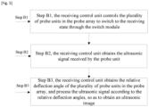
the receiving process comprises: - Step B1, the receiving control unit controls the plurality of probe units in the probe array to switch to the receiving state through the switch module;
- Step B2, the receiving control unit obtains the ultrasonic signal received by the probe unit; and
- Step B3, the receiving control unit obtains the relative deflection angles of the plurality of probe unit in the probe array, and process the ultrasonic signal according to the relative deflection angles, so as to obtain an ultrasonic image.
- Preferably, Step B3 further comprises:
- Step B31: the beamforming element in the receiving control unit receives the ultrasonic signal, performs beamforming process on the ultrasonic signal based on the relative deflection angle, and outputs the ultrasonic signal;
- Step B32: the signal processing element in the receiving control unit receives the ultrasonic signal output by the beamforming element, filters and compresses the ultrasonic signal, and outputs the ultrasonic signal; and
- Step B33: the image processing element in the receiving control unit receives the ultrasonic signal output by the signal processing element, and performs frame-related processing on the ultrasonic signal to generate the ultrasonic image.
- By adopting the above-mentioned technical solutions, the present invention has the following beneficial effects: the use of a flexible probe for acquiring an ultrasonic image allows to solve the problem that the operation process and imaging steps are complicated when using a rigid probe, so that it is easier for relevant operators to carry out the process.
-
-
Figure 1 is a schematic diagram of an overall structure according to an embodiment of the present invention; -
Figure 2 is a schematic diagram of a flexible film sensor according to an embodiment of the present invention; -
Figure 3 is a schematic diagram of a transmitting control unit according to a preferred embodiment of the present invention; -
Figure 4 is a schematic flowchart of a transmitting process according to an embodiment of the present invention; -
Figure 5 is a schematic flowchart of a receiving process according a preferred embodiment of the present invention; - Figure 6 is a schematic flowchart of Step B3 in a preferred embodiment of the present invention.
- The technical solution set forth in the embodiments of the present invention will now be described clearly and fully hereinafter with reference to the accompanying drawings of the embodiments of the present invention. Obviously, such embodiments provided in the present invention are only part of the embodiments instead of all embodiments. Notably, the embodiments set forth in the present invention and features of the embodiments may be combined in any suitable manner.
- The invention provides an ultrasonic system of a contact type flexible conformal ultrasonic probe for generating an ultrasonic image, as shown in
Figure 1 , the ultrasonic system comprises: - a
flexible probe 1, comprising aflexible detection surface 12, a plurality ofprobe units 111, and a softfilm sensing surface 13, wherein the plurality ofprobe units 111 are configured to transmit/receive an ultrasonic signal, all of the plurality ofprobe units 111 form aprobe array 11, theprobe array 11 is positioned inside theflexible detection surface 12, theflexible detection surface 12 is connected to the flexiblefilm sensing surface 13 and changes with deformation of the flexiblefilm sensing surface 13, the flexiblefilm sensing surface 13 is provided with a capacitive sensor array therein, the capacitive sensor array is configured to detect the deformation of the flexiblefilm sensing surface 13 and to obtain relative deflection angles of each of the plurality ofprobe units 111 in theprobe array 11; - a
switch module 12, connected to theflexible probe 1, and configured to sequentially switch a transmitting/receiving state of each of the plurality ofprobe units 111 in theprobe array 11; - a
control module 3, connected to theflexible probe 1 and theswitch module 2, respectively, thecontrol module 3 comprising:- a transmitting
control unit 31 for acquiring the relative deflection angles of the plurality ofprobe unit 111 and generating corresponding delay times according to the relative deflection angles, and sequentially controlling the plurality ofprobe units 111 in theprobe array 11 to transmit the ultrasonic signal based on the delay times; and - a receiving
control unit 32, for sequentially controlling the plurality ofprobe units 111 in theprobe array 11 to receive the ultrasonic signal, for obtaining the relative deflection angles of the plurality ofprobe units 111, and for performing beamforming and image processing on the ultrasonic signal based on the relative deflection angles, so as to obtain the ultrasonic image.
- a transmitting
- Specifically, as described above, in the field of ultrasound imaging detection, the ultrasound image is obtained by using a rigid probe. However, the transmitting angle of each probe unit in the rigid probe, and relative positions between two of the probe units are fixed. Therefore, in order to perform ultrasound imaging by using the rigid probe, the rigid probe remains transmitting ultrasonic signal at a fixed angle, and an operator is required to pre-set the angle of the rigid probe, and the operator has to control the rigid probe to move around, so as to acquire an accurate ultrasound image. It can be seen from the above-mentioned steps that operation steps for carrying out ultrasound imaging by using the rigid probe is quite complicated.
- In the prior art, flexible probes are also used for some applications. It is much easier for operators to manipulate the flexible probes than to manipulate the rigid probes. At present, the flexible probes are often used in fields, for example, of the detection of a workpiece on an uneven surface and in A-mode ultrasound detection. A curve of the signal intensity of a detection beam over time or distance can be obtained simply by attaching the flexible probe to a surface to be detected. However, the flexible probes in the prior art cannot be used for ultrasound imaging detection, the key reason is that the ultrasonic signal cannot be focused during the transmitting and receiving process.
- In order to solve the above-mentioned defects, the present invention provides an ultrasonic system of a contact type flexible conformal ultrasonic probe, comprising: a
flexible probe 1, aswitch module 2 and acontrol module 3, and aflexible detection surface 12, a plurality ofprobe units 111 and a flexiblefilm sensing surface 13 are provided inside theflexible probe 1, the plurality ofprobe units 111 form aprobe array 11 and are arranged in theflexible detection surface 12. When an operator attaches theflexible probe 1 to the surface of the human body, theflexible detection surface 12 will deform with the flexiblefilm sensing surface 13. The capacitive sensing array located in the flexiblefilm sensing surface 13 can detect the deformation of the flexiblefilm sensing surface 13, so as to obtain a relative deflection angel of each of theprobe units 111 in theprobe array 11. Thecontrol module 3 and theswitch module 2 generate the corresponding delay times according to the relative deflection angles of eachprobe unit 111 to control the transmitting/receiving state of theprobe unit 111, to solve the focus problem of theprobe unit 111 in the transmitting/receiving process, and finally the function of theflexible probe 1 to acquire ultrasound images is realized. - In particular, the plurality of
probe units 111 form a two-dimensional probe array 11. Theprobe array 11 is disposed inside theflexible detection surface 12, and theflexible detection surface 12 is connected to the flexiblefilm sensing surface 13. In practice, when the operator attaches theflexible probe 1 to the body surface of the patient, the flexiblefilm sensing surface 13 may deform to conform to the contour of the surface of body, and consequently theflexible detection surface 12 may also deform. Finally, each of theprobe units 111 can form a different relative deflection angle in theprobe array 11. - Accordingly, in order to obtain the relative deflection angle of the
probe unit 11, a capacitance sensing array is arranged in the flexiblefilm sensing surface 13. The capacitance sensing array can detect the deformation of the flexiblefilm sensing surface 13, so as to obtain the relative deflection angle of theprobe unit 111 in the probe array and to output the relative deflection angle to theswitch module 2. Theswitch module 2 controls a transmitting/receiving state of eachprobe unit 111 according to the obtained relative deflection angle. Since theprobe array 11 in theflexible probe 1 has a plurality of rows and a plurality of columns, theswitch module 2 sequentially switches the state of each row ofprobe units 111 in theprobe array 11. After theprobe units 111 in one row have completed transmitting and receiving ultrasonic signal, next row ofprobe units 111 follow to transmit and receive ultrasonic signal. - Furthermore, in order to enable the
probe units 111 to focus during the transmitting process, thecontrol module 3 is provided with a transmittingcontrol unit 31 therein, a transmission focus is provided when transmitting the ultrasonic signal. When theflexible probe 1 transmits the ultrasonic signal, the transmittingcontrol unit 31 generates different delay times based on the relative deflection angles of eachprobe unit 111, so as to control all of theprobe units 111 in each group of theprobe array 11 to reach a preset focus at exactly the same time. - Furthermore, it is known that the probe unit needs to focus when transmitting the ultrasonic signal, while when receiving the ultrasonic signal, the
probe unit 111 also needs to focus, and the only difference lies in that the focus during the receiving process can be dynamically changed. Therefore, a receivingcontrol unit 32 is provided in thecontrol module 3. When theflexible probe 1 receives the returned ultrasonic signal, the ultrasonic signal received by each group of theprobe array 11 is processed sequentially according to the relative deflection angles, so that time delay compensation for the ultrasonic signal is achieved, and focus problem confronted by theflexible probe 1 during the receiving process can be solved, and finally, an ultrasonic image is obtained. - By adopting this technical solution, the flexible probe can be used for ultrasound imaging, the application fields to which the
flexible probe 1 applies increase, and it can partially replace rigid probes. In addition to that advantages, it can also simplify the operation steps for obtaining ultrasound images. Specifically, the operators only need to attach theflexible probe 1 to the surface of human body, then all of theprobe units 111 can achieve the focus for the transmitting/receiving process. The operators do not have to pre-set the location, the shape, and the angle of the flexible probe, and they also do not have to control the flexible probe to move around, but a complete ultrasound image can also be obtained. For example, in the field of medical applications, when it is desired to perform ultrasound imaging detection on the patient's elbow joint, what the operators need to do is only to hold theflexible probe 1 in the hand, and to attach theflexible probe 1 to the elbow joint, so that an ultrasound image for the elbow joint can be obtained. - As shown in
Figure 2 , the capacitive sensing array comprises: - a plurality of first
polar plates 131; - a plurality of second
polar plates 132, parallel to the plurality of firstpolar plates 131; - a plurality of third
polar plates 133, disposed between the plurality of firstpolar plates 131 and the plurality of secondpolar plates 132, and connected to theflexible detection surface 12, wherein a first capacitance value is set between the plurality of thirdpolar plates 133 and the plurality of firstpolar plates 131, a second capacitance value is set between the plurality of thirdpolar plates 133 and the plurality of secondpolar plates 132; - a first initial standard value is set correspondingly to the first capacitance value;
- a second initial standard value is set correspondingly to the second capacitance value;
- a detection element, wherein the detection element is connected to the first
polar plate 131, the secondpolar plate 132 and the thirdpolar plate 133, respectively for obtaining a first difference value between the first capacitance value and the first initial standard value, and for obtaining a second difference value between the second capacitance value and the second initial standard value, and for obtaining the relative deflection angle of each of the plurality of probe units in the probe array based on the first difference value and the second difference value. - Specifically, a capacitance sensing array is arranged in the flexible
film sensing surface 13, and a plurality offirst electrode plates 131, a plurality ofsecond electrode plates 132, and a plurality ofthird electrode plates 133 are arranged in the capacitance sensor array. When the operator attaches theflexible probe 1 to the human body, the flexiblefilm sensing surface 13 will deform along the contour of the human body. Theflexible detection surface 12 will also change with the deformation of the flexiblefilm sensing surface 13. Therefore, both the first capacitance value and the second capacitance value change, and the first difference value and the second difference value may also change. The relative deflection angle of each of theprobe units 111 in theprobe array 11 in a corresponding row ofprobe unit 111 can be obtained according to the change of the first capacitance value and the second capacitance value, and the location of theprobe unit 111 in theprobe array 11. - Furthermore, in a more preferred embodiment of the present invention, two first
polar plates 131, two secondpolar plates 132, and one thirdpolar plate 133 are provided. When theflexible probe 1 is attached to the surface of the human body, eachprobe unit 111 has two first difference values and two second difference values. The relative deflection angles of theprobe units 111 can be obtained by analyzing the difference values and taking into consideration the position of theprobe unit 11 in theprobe array 11. - In a more preferred embodiment of the present invention, after the relative deflection angles of the
probe units 111 are obtained, the delay time for each of theprobe unit 111 can be obtained by calculation the following formula:
wherein - τ (i, j) represents delay time of the
probe unit 111; - i represents the row serial number of the
probe unit 111 in theprobe array 11, j represents the column serial number of theprobe unit 111 in theprobe array 11; - ΔR (i.j) represents a sound path between the
probe unit 111 and a preset focus; and - c represents sound velocity.
- In a more preferred embodiment of the present invention, the sound path between the
probe unit 111 and the preset focus is expressed as:
- wherein r (i,j) represents spatial distance between the
probe unit 111 and a preset coordinate origin; - F represents the depth of the preset focus;
- β (i,j) represents the deflection angle between the
probe unit 111 and the preset coordinate origin. - Specifically, after the transmitting
control unit 31 obtains the relative deflection angles of theprobe unit 111, thefirst probe unit 11 in each row in theprobe array 11 can, by combining formula (2), be adopted as the coordinate origin, to establish a corresponding spatial coordinate system. In this way, the sound path between theprobe unit 111 and the preset focus is calculated, and then the transmittingcontrol unit 31 obtains, by combining formula (1), the delay times corresponding to eachprobe unit 111. - In conclusion, the relative deflection angles of the
flexible probe 1 in the ultrasound scanning can be obtained through the flexiblefilm sensing unit 13, and the delay time of eachprobe unit 111 can be obtained through the relative deflection angles. The delay time is then considered as a transmission parameter to control the transmitting sequence of each of theprobe units 111, so that transmission focus problem confronted by theflexible probe 1 during the ultrasound imaging process can be solved. - In a preferred embodiment of the present invention, the receiving
control unit 32 comprises: - a
beamforming element 321, connected to theflexible probe 1 and theswitch module 2, respectively, configured to obtain the relative deflection angles, configured to control each row ofprobe units 111 in theprobe array 11 to sequentially receive the ultrasonic signal through theswitch module 2, and configured to perform beamforming on the ultrasonic signal based on the relative deflection angle and output the ultrasonic signal; - a
signal processing element 322, connected to thebeamforming element 321, configured to receive the ultrasonic signal output by thebeamforming element 321, and configured to filter and compress the ultrasonic signal and output the ultrasonic signal; and - an
image processing element 323, connected to thesignal processing element 322, configured to receive the ultrasonic signal output by thesignal processing element 322, and configured to perform frame-related processing on the ultrasonic signal to generate the ultrasonic image. - Specifically, as shown in
Figure 3 , thebeamforming element 321 performs beamforming on the ultrasonic signal received by theprobe units 111 based on the relative deflection angles. The signal processing element performs dynamic filtering, logarithmic compression, and demodulation on the ultrasonic signal. Accordingly, the ultrasonic signal is affected by noise generated during the sampling process and analog-to-electrical conversion of the ultrasound signals, then the image is not smooth enough. Therefore, theimage processing element 323 performs frame-related processing and noise suppression on the ultrasound signal, and the ultrasound image is obtained. - In a more preferred embodiment of the present invention, the
beamforming element 321 is subjected to beamforming process by using the following formula:
- SDAS(t) represents the ultrasonic signal which is subjected to the beamforming process;
- s(t (i,j)) represents the ultrasonic signal received by the
probe unit 111; - i represents a row serial number of the
probe unit 111 in theprobe array 11, n represents the number of rows in theprobe array 11; - j represents a column serial number of the
probe unit 111 in theprobe array 11, m represents the number of columns in theprobe array 11; - t'(i,j) represents a transmission time of ultrasonic waves;
- τ (i.j) represents the delay time of the
probe unit 111. - Specifically, after each row of the
probe units 111 in theprobe array 11 transmit ultrasonic signal, theprobe units 111 in the row start to receive the returned ultrasonic signal. After all theprobe units 111 in the row have received the returned ultrasonic signal, next row ofprobe units 111 begin to transmit and receive the ultrasonic signal. It shows that data finally processed by each row of theprobe units 111 are related to the relative deflection angle. Therefore, when the receivingcontrol unit 32 performs beamforming, and when theprobe units 111 receive the ultrasonic signal and perform beamforming, it is necessary to carry out a geometrical operation, by using the formula (2), for the relative deflection angle and the positional information of eachprobe unit 111, then the ultrasonic signal subjected to the beamforming process is obtained. - In conclusion, the
beamforming element 321 can obtain the delay time of eachprobe unit 111 based on the relative deflection angle of theflexible probe 1 in the ultrasound scanning. The delay time is then considered as a receiving parameter to control the receiving sequence of each of theprobe units 111, so that the receiving compensation for the ultrasonic signal is achieved, and focus problem confronted by theflexible probe 1 during the receiving process can be solved. - Therefore, after solving the transmitting focusing problem and the receiving focusing problem, the
flexible probe 1 can be applied in the field of ultrasonic scanning and imaging technology as a detection terminal for ultrasonic scanning, so that the problem of rigid probes in the prior art can be solved, in which the problems refer to a complex operation and imaging steps of the rigid probes when they are applied to the fields of the ultrasonic scanning and imaging technology. - In a more preferred embodiment of the present invention, the ultrasonic system of a contact type flexible conformal ultrasonic probe further comprises a client, wherein the client is connected to the receiving
control unit 32 for obtaining the ultrasonic image and displaying the obtained ultrasonic image. - Specifically, in order to allow the operator to view the ultrasonic image for user interaction, a client is arranged in the ultrasonic system. The client can obtain the ultrasonic image and display the ultrasonic image.
- The invention further provides an ultrasonic method for a contact type flexible conformal ultrasonic probe, applied to any one of the ultrasonic systems for generating an ultrasonic image, wherein the ultrasonic method comprises the process of a
flexible probe 1 transmitting the ultrasonic signal;
the transmitting process comprises: - Step A1, the transmitting
control unit 31 controls the plurality ofprobe units 111 in theprobe array 11 to switch to the transmitting state through theswitch module 31; - Step A2, the transmitting
control unit 31 obtains the relative deflection angles of the plurality ofprobe units 111 in theprobe array 11, and generates delay times according to the relative deflection angles; and - Step A3, the transmitting
control unit 31 controls the plurality ofprobe units 111 to transmit ultrasonic signal according to the delay times. - Specifically, as shown in
Figure 4 , theflexible probe 1 comprises aprobe array 11, and theprobe array 11 comprises a plurality ofprobe units 111. When theprobe units 111 transmit ultrasonic signal, in Step A1, the transmittingcontrol unit 31 controls all theprobe units 111 in the current row in theprobe array 11 to be switched to the transmitting state, and then in Step A2, the transmittingcontrol unit 31 obtains the relative deflection angles of all theprobe units 111 in the current row, and generates the delay times corresponding to eachprobe unit 111 according to the respective relative deflection angles, so that all theprobe units 111 in the current row can reach the focus at the same time in Step A3. - In a preferred embodiment of the present invention, the ultrasonic method further comprises the process of the
flexible probe 1 receiving the ultrasonic signal;
the receiving process comprises: - Step B1, the receiving
control unit 32 controls the plurality ofprobe units 111 in theprobe array 11 to switch to the receiving state through theswitch module 2; - Step B2, the receiving
control unit 32 obtains the ultrasonic signal received by theprobe units 111; and - Step B3, the receiving
control unit 32 obtains the relative deflection angles of the plurality ofprobe unit 111 in theprobe array 11, and process the ultrasonic signal according to the relative deflection angle, so as to obtain an ultrasonic image. - Specifically, as shown in
Figure 5 , when theprobe units 111 receive ultrasonic signal, in Step B1, the transmittingcontrol unit 31 controls all theprobe units 111 in the current row in theprobe array 11 to be switched to the receiving state, and then in Step B2, the transmittingcontrol unit 31 obtains the ultrasonic signal received by all theprobe units 111 in the current row. As a result, the relative deflection angles of theprobe units 111 in theprobe array 11 can be obtained in Step B3, and the ultrasonic signal is processed according to the relative deflection angles, so that the ultrasound image is obtained. - In a preferred embodiment of the present invention, Step B3 further comprises:
- Step B31: the
beamforming element 321 in the receivingcontrol unit 32 receives the ultrasonic signal, performs beamforming process on the ultrasonic signal based on the relative deflection angle, and outputs the ultrasonic signal; - Step B32: the
signal processing element 322 in the receivingcontrol unit 32 receives the ultrasonic signal output by thebeamforming element 321, filters and compresses the ultrasonic signal, and outputs the ultrasonic signal; and - Step B33: the
image processing element 323 in the receivingcontrol unit 32 receives the ultrasonic signal output by thesignal processing element 322, and performs frame-related processing on the ultrasonic signal to generate the ultrasonic image. - Specifically, as shown in Figure 6, in Step B31, the
beamforming element 321 performs beamforming process on the ultrasonic signal received by theprobe unit 111 based on the relative deflection angle; in Step B32, the signal processing element performs dynamic filtering, logarithmic compression, demodulation, and dynamic processing on the ultrasonic signal; and in Step B33, theimage processing element 323 may perform frame-related processing and noise suppression processing on the ultrasonic signal; finally, the ultrasonic image is generated.
Claims (9)
- An ultrasonic system of a contact type flexible conformal ultrasonic probe for generating an ultrasonic image, comprising:a flexible probe (1), comprising a flexible detection surface (12), a plurality of probe units (111), and a flexible film sensing surface (13), wherein the plurality of probe units (111) are configured to transmit/receive an ultrasonic signal, all of the plurality of probe units (111) form a probe array (11), the probe array (11) is positioned inside the flexible detection surface (12), the flexible detection surface (12) is connected to the flexible film sensing surface (13) and changes with deformation of the flexible film sensing surface (13), the flexible film sensing surface (13) is provided with a capacitive sensor array therein, the capacitive sensor array comprises a plurality of first polar plates (131) and a plurality of second polar plates (132) parallel to the plurality of first polar plates (131), and is configured to detect the deformation of the flexible film sensing surface (13) and to obtain relative deflection angles of each of the plurality of probe units (111) in the probe array (11);a switch module (2), connected to the flexible probe (1), and configured to sequentially switch a transmitting /receiving state of each of plurality of the probe units (111) in the probe array (11);a control module (3), connected to the flexible probe (1) and the switch module (2), respectively, the control module (3) comprising:a transmitting control unit (31) for acquiring the relative deflection angles of the plurality of probe units (111) and generating corresponding delay times according to the relative deflection angles, and sequentially controlling the plurality of probe units (111) in the probe array (11) to transmit the ultrasonic signal according to the delay times; anda receiving control unit (32) for sequentially controlling the plurality of probe units (111) in the probe array (11) to receive the ultrasonic signal, and for obtaining the relative deflection angles of plurality of probe units (111), and for performing beamforming and image processing on the ultrasonic signal, so as to obtain the ultrasonic image;wherein the capacitive sensor array further comprises:a plurality of third polar plates (133), disposed between the plurality of first polar plates (131) and the plurality of second polar plates (132), and connected to the flexible detection surface (12), wherein a first capacitance value is respectively set between the plurality of third polar plates (133) and the plurality of first polar plates (131), a second capacitance value is respectively set between the plurality of third polar plates (133) and the plurality of second polar plates (132);a first initial standard value is set correspondingly to the first capacitance value;a second initial standard value is set correspondingly to the second capacitance value;a detection element, wherein the detection element is connected to a corresponding first polar plate (131), a corresponding second polar plate (132) and a corresponding third polar plate (133), respectively, for obtaining a first difference value between the first capacitance value and the first initial standard value, and for obtaining a second difference value between the second capacitance value and the second initial standard value, and for obtaining the relative deflection angle of each of the plurality of probe units (111) in the probe array (11) based on the first difference value and the second difference value.
- The ultrasonic system of a contact type flexible conformal ultrasonic probe of claim 1, wherein the delay time is expressed as

Whereinτ (i,j) represents delay time of one of the plurality of probe units (111);i represents a row serial number of the one of the plurality of probe units (111) in the probe array (11), j represents a column serial number of the one of the plurality of probe units (111) in the probe array (11);ΔR(i.j) represents a sound path between the one of the plurality of probe units (111) and a preset focus; andc represents sound velocity. - The ultrasonic system of a contact type flexible conformal ultrasonic probe of claim 2, wherein the sound path between the one of the plurality of probe units (111) and the preset focus is expressed as:
 wherein r (i,j) represents spatial distance between the one of the plurality of probe units (111) and a preset coordinate origin;F represents the depth of the preset focus;β (i,j) represents the deflection angle between the one of the plurality of probe units (111) and the preset coordinate origin.
 - The ultrasonic system of a contact type flexible conformal ultrasonic probe
of claim 1, wherein the receiving control unit (32) comprises:a beamforming element (321), connected to the flexible probe (1) and the switch module (2), respectively, configured to obtain the relative deflection angles of the plurality of probe units (111), configured to control each row of the plurality of probe units (111) in the probe array (11) to sequentially receive the ultrasonic signal through the switch module (2), and configured to perform beamforming on the ultrasonic signal based on the relative deflection angles and output the ultrasonic signal;a signal processing element (322), connected to the beamforming element (321), configured to receive the ultrasonic signal output by the beamforming element (321), and configured to filter and compress the ultrasonic signal and output the ultrasonic signal; andan image processing element (323), connected to the signal processing element (322), configured to receive the ultrasonic signal output by the signal processing element (322), and configured to perform frame-related processing on the ultrasonic signal to generate the ultrasonic image. - The ultrasonic system of a contact type flexible conformal ultrasonic probe of claim 4, wherein the beamforming element (321) is subjected to beamforming process by using the following formula:
 SDAS(t) represents the ultrasonic signal which is subjected to the beamforming process;s(t (i,j)) represents the ultrasonic signal received by one of the plurality of probe units (111);i represents a row serial number of the one of the plurality of probe units (111) in the probe array (11), n represents a number of rows of the plurality of probe units (111) in the probe array (11);j represents a column serial number of the one of the plurality of probe units (111) in the probe array (11), m represents a number of columns of the plurality of probe units (111) in the probe array (11);t'(i, j) represents a transmission time of ultrasonic waves;τ (i.j) represents the delay time of the one of plurality of probe units (111).
 - The ultrasonic system of a contact type flexible conformal ultrasonic probe of claim 1, further comprising:
a client, wherein the client is connected to the receiving control unit (32) for obtaining the ultrasonic image and displaying the ultrasonic image. - An ultrasonic method for a contact type flexible conformal ultrasonic probe, applied to the ultrasonic system of any one of claims 1-6 for generating an ultrasonic image, wherein the ultrasonic method comprises the process of a flexible probe (1) transmitting the ultrasonic signal;
the transmitting process comprises:Step A1, the transmitting control unit (31) controls the plurality of probe units (111) in the probe array (11) to switch to the transmitting state through the switch module (2);Step A2, the transmitting control unit (31) obtains the relative deflection angles of the plurality of probe units (111) in the probe array (11), and generates delay times according to the relative deflection angles; andStep A3, the transmitting control unit (31) controls the plurality of probe units (111) to transmit ultrasonic signal according to the delay times. - The ultrasonic method for a contact type flexible conformal ultrasonic probe of claim 7, wherein the ultrasonic method further comprises the process of the flexible probe (1) receiving the ultrasonic signal;
the receiving process comprises:Step B1, the receiving control unit (32) controls the plurality of probe units (111) in the probe array (11) to switch to the receiving state through the switch module (2);Step B2, the receiving control unit (32) obtains the ultrasonic signal received by the probe unit (111); andStep B3, the receiving control unit (32) obtains the relative deflection angles of the plurality of probe units (111) in the probe array (11), and process the ultrasonic signal according to the relative deflection angles, so as to obtain an ultrasonic image. - The ultrasonic method for a contact type flexible conformal ultrasonic probe of claim 8, wherein Step B3 further comprises:Step B31: the beamforming element (321) in the receiving control unit (32) receives the ultrasonic signal, performs beamforming process on the ultrasonic signal based on the relative deflection angles, and outputs the ultrasonic signal;Step B32: the signal processing element (322) in the receiving control unit (32) receives the ultrasonic signal output by the beamforming element (321), filters and compresses the ultrasonic signal, and outputs the ultrasonic signal;Step B33: the image processing element (323) in the receiving control unit (32) receives the ultrasonic signal output by the signal processing element (322), and performs frame-related processing on the ultrasonic signal to generate the ultrasonic image.
Applications Claiming Priority (1)
| Application Number | Priority Date | Filing Date | Title |
|---|---|---|---|
| CN202010272050.0A CN111184532B (en) | 2020-04-09 | 2020-04-09 | Ultrasonic system and method of contact type flexible conformal ultrasonic probe |
Publications (2)
| Publication Number | Publication Date |
|---|---|
| EP3893024A1 EP3893024A1 (en) | 2021-10-13 |
| EP3893024B1 true EP3893024B1 (en) | 2023-11-29 |
Family
ID=70703176
Family Applications (1)
| Application Number | Title | Priority Date | Filing Date |
|---|---|---|---|
| EP21167558.2A Active EP3893024B1 (en) | 2020-04-09 | 2021-04-09 | Ultrasonic system of contact type flexible conformal ultrasonic probe and method for the same |
Country Status (3)
| Country | Link |
|---|---|
| US (1) | US11510654B2 (en) |
| EP (1) | EP3893024B1 (en) |
| CN (1) | CN111184532B (en) |
Families Citing this family (7)
| Publication number | Priority date | Publication date | Assignee | Title |
|---|---|---|---|---|
| KR102465348B1 (en) * | 2020-06-11 | 2022-11-11 | 한국과학기술연구원 | Method for determining relative position between arrays of flexible array device |
| CN114145767B (en) * | 2021-11-30 | 2024-04-19 | 京东方科技集团股份有限公司 | Acoustic wave probe, positioning method of acoustic wave receiving array element of acoustic wave probe and imaging method of acoustic wave receiving array element |
| CN117918895B (en) * | 2024-01-19 | 2024-08-20 | 华中科技大学 | Intracranial/in-vivo cavity signal monitoring sensor and preparation method and system thereof |
| CN117838190B (en) * | 2024-03-08 | 2024-05-28 | 中国医学科学院北京协和医院 | Myocardial function index measurement method and device |
| CN118031866B (en) * | 2024-04-11 | 2024-06-14 | 北京航空航天大学 | Flexible ultrasonic sensor receiving device and system |
| CN118299039B (en) * | 2024-04-12 | 2025-01-21 | 东莞索诺星科技有限公司 | A three-dimensional imaging and interactive method of ultrasonic detector |
| CN118576240B (en) * | 2024-05-31 | 2025-11-07 | 中国科学院苏州生物医学工程技术研究所 | Wearable ultrasonic imaging method and device |
Family Cites Families (21)
| Publication number | Priority date | Publication date | Assignee | Title |
|---|---|---|---|---|
| US6153463A (en) * | 1999-07-09 | 2000-11-28 | Macronix International Co., Ltd. | Triple plate capacitor and method for manufacturing |
| US6572547B2 (en) * | 2001-07-31 | 2003-06-03 | Koninklijke Philips Electronics N.V. | Transesophageal and transnasal, transesophageal ultrasound imaging systems |
| US6875178B2 (en) * | 2002-06-27 | 2005-04-05 | Siemens Medical Solutions Usa, Inc. | Receive circuit for ultrasound imaging |
| US7135874B2 (en) * | 2004-08-06 | 2006-11-14 | Waters Investments Limited | System and method for enhanced measurement of rheological properties |
| CN101152646B (en) * | 2006-09-27 | 2012-07-04 | 香港理工大学 | flexible ultrasonic transducer array and application device thereof |
| JP2008142323A (en) * | 2006-12-11 | 2008-06-26 | Aloka Co Ltd | Ultrasonic probe and ultrasonic diagnostic apparatus |
| US20120179044A1 (en) * | 2009-09-30 | 2012-07-12 | Alice Chiang | Ultrasound 3d imaging system |
| FR2965923B1 (en) * | 2010-10-11 | 2012-12-14 | Commissariat Energie Atomique | ULTRASONIC SURVEY DEVICE, METHOD FOR CONTROLLING TRANSDUCERS OF ULTRASONIC PROBE AND CORRESPONDING COMPUTER PROGRAM |
| US9310485B2 (en) * | 2011-05-12 | 2016-04-12 | Georgia Tech Research Corporation | Compact, energy-efficient ultrasound imaging probes using CMUT arrays with integrated electronics |
| JP5799640B2 (en) * | 2011-07-29 | 2015-10-28 | 株式会社村田製作所 | Electrostrictive sensor |
| JP5497222B2 (en) * | 2012-09-28 | 2014-05-21 | バンドー化学株式会社 | Capacitance type sensor sheet and method for manufacturing capacitance type sensor sheet |
| AU2014231327C1 (en) * | 2013-03-15 | 2019-08-01 | Conavi Medical Inc. | Active localization and visualization of minimally invasive devices using ultrasound |
| KR20150000627A (en) * | 2013-06-25 | 2015-01-05 | 삼성전자주식회사 | Ultrasonic imaging apparatus and control method for thereof |
| KR102373132B1 (en) * | 2014-12-26 | 2022-03-11 | 삼성메디슨 주식회사 | An ultrasonic probe apparatus and an ultrasonic imaging apparatus using the same |
| CN105877780B (en) * | 2015-08-25 | 2019-05-31 | 上海深博医疗器械有限公司 | Fully-automatic ultrasonic scanner and scanning detection method |
| CN106102588B (en) * | 2015-09-06 | 2019-04-23 | 深圳迈瑞生物医疗电子股份有限公司 | Ultrasound grayscale imaging system and method |
| WO2017182344A1 (en) * | 2016-04-19 | 2017-10-26 | Koninklijke Philips N.V. | Ultrasound transducer positioning |
| US10602989B2 (en) * | 2016-09-02 | 2020-03-31 | Canon U.S.A., Inc. | Capacitive sensing and encoding for imaging probes |
| CN108444436A (en) * | 2018-02-28 | 2018-08-24 | 西安交通大学 | A kind of hand gestures measuring system and method based on flexible large deformation sensor |
| CN109674491A (en) * | 2019-02-13 | 2019-04-26 | 飞依诺科技(苏州)有限公司 | Ultrasonic imaging wide-beam transmission method and emission system |
| CN110680381B (en) * | 2019-09-03 | 2021-11-30 | 东软医疗系统股份有限公司 | Medical 1. X-dimensional ultrasonic probe and medical ultrasonic diagnosis system |
-
2020
- 2020-04-09 CN CN202010272050.0A patent/CN111184532B/en active Active
-
2021
- 2021-04-05 US US17/222,649 patent/US11510654B2/en active Active
- 2021-04-09 EP EP21167558.2A patent/EP3893024B1/en active Active
Also Published As
| Publication number | Publication date |
|---|---|
| EP3893024A1 (en) | 2021-10-13 |
| US11510654B2 (en) | 2022-11-29 |
| US20210315544A1 (en) | 2021-10-14 |
| CN111184532B (en) | 2020-07-31 |
| CN111184532A (en) | 2020-05-22 |
Similar Documents
| Publication | Publication Date | Title |
|---|---|---|
| US11510654B2 (en) | Ultrasonic system of contact type flexible conformal ultrasonic probe and method for the same | |
| CN113164156B (en) | Systems and methods for guided ultrasound data acquisition | |
| EP1504289B1 (en) | Ultrasound transducer | |
| JP6030825B2 (en) | Ultrasonic method for removing electromagnetic noise | |
| JP7449406B2 (en) | Medical detection system and deployment method | |
| US11559276B2 (en) | Systems and methods for ultrasound screening | |
| EP3316791B1 (en) | Multi-mode capacitive micromachined ultrasound transducer and associated devices and systems | |
| WO2019064706A1 (en) | Ultrasonic diagnostic device and method for controlling ultrasonic diagnostic device | |
| EP3053529B1 (en) | Medical ultrasonic apparatus for generating a movement-amplified image and method of controlling the same | |
| US20220211341A1 (en) | Muscle imaging system | |
| EP3884872B1 (en) | Ultrasound imaging apparatus and control method thereof | |
| EP1890282B1 (en) | Ultrasound system and method for controlling steering angles of scan lines | |
| US12004902B2 (en) | Systems and methods for performing bi-plane imaging | |
| EP3771498B1 (en) | Ultrasound probe and ultrasound diagnosis apparatus | |
| JP2000245733A (en) | Ultrasonic image pickup method and device | |
| US20140180090A1 (en) | Ultrasound diagnostic apparatus, tissue elasticity measurement method, and recording medium | |
| JPH01145043A (en) | Ultrasonic diagnostic apparatus | |
| JP2008253663A (en) | Ultrasonic diagnostic apparatus and control processing program thereof | |
| CN102046092A (en) | Tissue strain analysis | |
| EP3772333A1 (en) | Muscle imaging system | |
| EP4498922B1 (en) | Generating an ultrasound device interaction indicator | |
| EP4252667A1 (en) | System and method for generating an ultrasound device interaction indicator | |
| KR20200089000A (en) | Ultrasound image apparatus and method for controlling thereof | |
| JP2013244136A (en) | Ultrasonic diagnostic equipment and ultrasonic diagnostic image generation method | |
| WO2021028243A1 (en) | Systems and methods for guiding the acquisition of ultrasound data |
Legal Events
| Date | Code | Title | Description |
|---|---|---|---|
| PUAI | Public reference made under article 153(3) epc to a published international application that has entered the european phase |
Free format text: ORIGINAL CODE: 0009012 |
|
| STAA | Information on the status of an ep patent application or granted ep patent |
Free format text: STATUS: THE APPLICATION HAS BEEN PUBLISHED |
|
| AK | Designated contracting states |
Kind code of ref document: A1 Designated state(s): AL AT BE BG CH CY CZ DE DK EE ES FI FR GB GR HR HU IE IS IT LI LT LU LV MC MK MT NL NO PL PT RO RS SE SI SK SM TR |
|
| STAA | Information on the status of an ep patent application or granted ep patent |
Free format text: STATUS: REQUEST FOR EXAMINATION WAS MADE |
|
| 17P | Request for examination filed |
Effective date: 20220407 |
|
| RBV | Designated contracting states (corrected) |
Designated state(s): AL AT BE BG CH CY CZ DE DK EE ES FI FR GB GR HR HU IE IS IT LI LT LU LV MC MK MT NL NO PL PT RO RS SE SI SK SM TR |
|
| GRAP | Despatch of communication of intention to grant a patent |
Free format text: ORIGINAL CODE: EPIDOSNIGR1 |
|
| STAA | Information on the status of an ep patent application or granted ep patent |
Free format text: STATUS: GRANT OF PATENT IS INTENDED |
|
| RIC1 | Information provided on ipc code assigned before grant |
Ipc: A61B 8/08 20060101ALN20230526BHEP Ipc: A61B 8/00 20060101ALN20230526BHEP Ipc: G10K 11/34 20060101ALI20230526BHEP Ipc: B06B 1/06 20060101ALI20230526BHEP Ipc: B06B 1/02 20060101ALI20230526BHEP Ipc: G01S 7/52 20060101ALI20230526BHEP Ipc: G01S 15/89 20060101AFI20230526BHEP |
|
| INTG | Intention to grant announced |
Effective date: 20230622 |
|
| GRAS | Grant fee paid |
Free format text: ORIGINAL CODE: EPIDOSNIGR3 |
|
| GRAA | (expected) grant |
Free format text: ORIGINAL CODE: 0009210 |
|
| STAA | Information on the status of an ep patent application or granted ep patent |
Free format text: STATUS: THE PATENT HAS BEEN GRANTED |
|
| AK | Designated contracting states |
Kind code of ref document: B1 Designated state(s): AL AT BE BG CH CY CZ DE DK EE ES FI FR GB GR HR HU IE IS IT LI LT LU LV MC MK MT NL NO PL PT RO RS SE SI SK SM TR |
|
| REG | Reference to a national code |
Ref country code: GB Ref legal event code: FG4D |
|
| REG | Reference to a national code |
Ref country code: CH Ref legal event code: EP |
|
| REG | Reference to a national code |
Ref country code: DE Ref legal event code: R096 Ref document number: 602021007172 Country of ref document: DE |
|
| REG | Reference to a national code |
Ref country code: IE Ref legal event code: FG4D |
|
| REG | Reference to a national code |
Ref country code: LT Ref legal event code: MG9D |
|
| REG | Reference to a national code |
Ref country code: NL Ref legal event code: MP Effective date: 20231129 |
|
| PG25 | Lapsed in a contracting state [announced via postgrant information from national office to epo] |
Ref country code: GR Free format text: LAPSE BECAUSE OF FAILURE TO SUBMIT A TRANSLATION OF THE DESCRIPTION OR TO PAY THE FEE WITHIN THE PRESCRIBED TIME-LIMIT Effective date: 20240301 |
|
| PG25 | Lapsed in a contracting state [announced via postgrant information from national office to epo] |
Ref country code: IS Free format text: LAPSE BECAUSE OF FAILURE TO SUBMIT A TRANSLATION OF THE DESCRIPTION OR TO PAY THE FEE WITHIN THE PRESCRIBED TIME-LIMIT Effective date: 20240329 |
|
| PG25 | Lapsed in a contracting state [announced via postgrant information from national office to epo] |
Ref country code: LT Free format text: LAPSE BECAUSE OF FAILURE TO SUBMIT A TRANSLATION OF THE DESCRIPTION OR TO PAY THE FEE WITHIN THE PRESCRIBED TIME-LIMIT Effective date: 20231129 |
|
| PG25 | Lapsed in a contracting state [announced via postgrant information from national office to epo] |
Ref country code: ES Free format text: LAPSE BECAUSE OF FAILURE TO SUBMIT A TRANSLATION OF THE DESCRIPTION OR TO PAY THE FEE WITHIN THE PRESCRIBED TIME-LIMIT Effective date: 20231129 |
|
| PG25 | Lapsed in a contracting state [announced via postgrant information from national office to epo] |
Ref country code: LT Free format text: LAPSE BECAUSE OF FAILURE TO SUBMIT A TRANSLATION OF THE DESCRIPTION OR TO PAY THE FEE WITHIN THE PRESCRIBED TIME-LIMIT Effective date: 20231129 Ref country code: IS Free format text: LAPSE BECAUSE OF FAILURE TO SUBMIT A TRANSLATION OF THE DESCRIPTION OR TO PAY THE FEE WITHIN THE PRESCRIBED TIME-LIMIT Effective date: 20240329 Ref country code: GR Free format text: LAPSE BECAUSE OF FAILURE TO SUBMIT A TRANSLATION OF THE DESCRIPTION OR TO PAY THE FEE WITHIN THE PRESCRIBED TIME-LIMIT Effective date: 20240301 Ref country code: ES Free format text: LAPSE BECAUSE OF FAILURE TO SUBMIT A TRANSLATION OF THE DESCRIPTION OR TO PAY THE FEE WITHIN THE PRESCRIBED TIME-LIMIT Effective date: 20231129 Ref country code: BG Free format text: LAPSE BECAUSE OF FAILURE TO SUBMIT A TRANSLATION OF THE DESCRIPTION OR TO PAY THE FEE WITHIN THE PRESCRIBED TIME-LIMIT Effective date: 20240229 |
|
| REG | Reference to a national code |
Ref country code: AT Ref legal event code: MK05 Ref document number: 1636689 Country of ref document: AT Kind code of ref document: T Effective date: 20231129 |
|
| PG25 | Lapsed in a contracting state [announced via postgrant information from national office to epo] |
Ref country code: NL Free format text: LAPSE BECAUSE OF FAILURE TO SUBMIT A TRANSLATION OF THE DESCRIPTION OR TO PAY THE FEE WITHIN THE PRESCRIBED TIME-LIMIT Effective date: 20231129 |
|
| PG25 | Lapsed in a contracting state [announced via postgrant information from national office to epo] |
Ref country code: SE Free format text: LAPSE BECAUSE OF FAILURE TO SUBMIT A TRANSLATION OF THE DESCRIPTION OR TO PAY THE FEE WITHIN THE PRESCRIBED TIME-LIMIT Effective date: 20231129 Ref country code: RS Free format text: LAPSE BECAUSE OF FAILURE TO SUBMIT A TRANSLATION OF THE DESCRIPTION OR TO PAY THE FEE WITHIN THE PRESCRIBED TIME-LIMIT Effective date: 20231129 Ref country code: PL Free format text: LAPSE BECAUSE OF FAILURE TO SUBMIT A TRANSLATION OF THE DESCRIPTION OR TO PAY THE FEE WITHIN THE PRESCRIBED TIME-LIMIT Effective date: 20231129 Ref country code: NO Free format text: LAPSE BECAUSE OF FAILURE TO SUBMIT A TRANSLATION OF THE DESCRIPTION OR TO PAY THE FEE WITHIN THE PRESCRIBED TIME-LIMIT Effective date: 20240229 Ref country code: NL Free format text: LAPSE BECAUSE OF FAILURE TO SUBMIT A TRANSLATION OF THE DESCRIPTION OR TO PAY THE FEE WITHIN THE PRESCRIBED TIME-LIMIT Effective date: 20231129 Ref country code: LV Free format text: LAPSE BECAUSE OF FAILURE TO SUBMIT A TRANSLATION OF THE DESCRIPTION OR TO PAY THE FEE WITHIN THE PRESCRIBED TIME-LIMIT Effective date: 20231129 Ref country code: HR Free format text: LAPSE BECAUSE OF FAILURE TO SUBMIT A TRANSLATION OF THE DESCRIPTION OR TO PAY THE FEE WITHIN THE PRESCRIBED TIME-LIMIT Effective date: 20231129 |
|
| PG25 | Lapsed in a contracting state [announced via postgrant information from national office to epo] |
Ref country code: DK Free format text: LAPSE BECAUSE OF FAILURE TO SUBMIT A TRANSLATION OF THE DESCRIPTION OR TO PAY THE FEE WITHIN THE PRESCRIBED TIME-LIMIT Effective date: 20231129 |
|
| PG25 | Lapsed in a contracting state [announced via postgrant information from national office to epo] |
Ref country code: CZ Free format text: LAPSE BECAUSE OF FAILURE TO SUBMIT A TRANSLATION OF THE DESCRIPTION OR TO PAY THE FEE WITHIN THE PRESCRIBED TIME-LIMIT Effective date: 20231129 Ref country code: AT Free format text: LAPSE BECAUSE OF FAILURE TO SUBMIT A TRANSLATION OF THE DESCRIPTION OR TO PAY THE FEE WITHIN THE PRESCRIBED TIME-LIMIT Effective date: 20231129 |
|
| PG25 | Lapsed in a contracting state [announced via postgrant information from national office to epo] |
Ref country code: SK Free format text: LAPSE BECAUSE OF FAILURE TO SUBMIT A TRANSLATION OF THE DESCRIPTION OR TO PAY THE FEE WITHIN THE PRESCRIBED TIME-LIMIT Effective date: 20231129 |
|
| PG25 | Lapsed in a contracting state [announced via postgrant information from national office to epo] |
Ref country code: SM Free format text: LAPSE BECAUSE OF FAILURE TO SUBMIT A TRANSLATION OF THE DESCRIPTION OR TO PAY THE FEE WITHIN THE PRESCRIBED TIME-LIMIT Effective date: 20231129 Ref country code: SK Free format text: LAPSE BECAUSE OF FAILURE TO SUBMIT A TRANSLATION OF THE DESCRIPTION OR TO PAY THE FEE WITHIN THE PRESCRIBED TIME-LIMIT Effective date: 20231129 Ref country code: RO Free format text: LAPSE BECAUSE OF FAILURE TO SUBMIT A TRANSLATION OF THE DESCRIPTION OR TO PAY THE FEE WITHIN THE PRESCRIBED TIME-LIMIT Effective date: 20231129 Ref country code: IT Free format text: LAPSE BECAUSE OF FAILURE TO SUBMIT A TRANSLATION OF THE DESCRIPTION OR TO PAY THE FEE WITHIN THE PRESCRIBED TIME-LIMIT Effective date: 20231129 Ref country code: EE Free format text: LAPSE BECAUSE OF FAILURE TO SUBMIT A TRANSLATION OF THE DESCRIPTION OR TO PAY THE FEE WITHIN THE PRESCRIBED TIME-LIMIT Effective date: 20231129 Ref country code: DK Free format text: LAPSE BECAUSE OF FAILURE TO SUBMIT A TRANSLATION OF THE DESCRIPTION OR TO PAY THE FEE WITHIN THE PRESCRIBED TIME-LIMIT Effective date: 20231129 Ref country code: CZ Free format text: LAPSE BECAUSE OF FAILURE TO SUBMIT A TRANSLATION OF THE DESCRIPTION OR TO PAY THE FEE WITHIN THE PRESCRIBED TIME-LIMIT Effective date: 20231129 Ref country code: AT Free format text: LAPSE BECAUSE OF FAILURE TO SUBMIT A TRANSLATION OF THE DESCRIPTION OR TO PAY THE FEE WITHIN THE PRESCRIBED TIME-LIMIT Effective date: 20231129 |
|
| PG25 | Lapsed in a contracting state [announced via postgrant information from national office to epo] |
Ref country code: PT Free format text: LAPSE BECAUSE OF FAILURE TO SUBMIT A TRANSLATION OF THE DESCRIPTION OR TO PAY THE FEE WITHIN THE PRESCRIBED TIME-LIMIT Effective date: 20240401 |
|
| PG25 | Lapsed in a contracting state [announced via postgrant information from national office to epo] |
Ref country code: PT Free format text: LAPSE BECAUSE OF FAILURE TO SUBMIT A TRANSLATION OF THE DESCRIPTION OR TO PAY THE FEE WITHIN THE PRESCRIBED TIME-LIMIT Effective date: 20240401 |
|
| REG | Reference to a national code |
Ref country code: DE Ref legal event code: R097 Ref document number: 602021007172 Country of ref document: DE |
|
| PLBE | No opposition filed within time limit |
Free format text: ORIGINAL CODE: 0009261 |
|
| STAA | Information on the status of an ep patent application or granted ep patent |
Free format text: STATUS: NO OPPOSITION FILED WITHIN TIME LIMIT |
|
| PG25 | Lapsed in a contracting state [announced via postgrant information from national office to epo] |
Ref country code: SI Free format text: LAPSE BECAUSE OF FAILURE TO SUBMIT A TRANSLATION OF THE DESCRIPTION OR TO PAY THE FEE WITHIN THE PRESCRIBED TIME-LIMIT Effective date: 20231129 |
|
| PG25 | Lapsed in a contracting state [announced via postgrant information from national office to epo] |
Ref country code: SI Free format text: LAPSE BECAUSE OF FAILURE TO SUBMIT A TRANSLATION OF THE DESCRIPTION OR TO PAY THE FEE WITHIN THE PRESCRIBED TIME-LIMIT Effective date: 20231129 |
|
| 26N | No opposition filed |
Effective date: 20240830 |
|
| PG25 | Lapsed in a contracting state [announced via postgrant information from national office to epo] |
Ref country code: MC Free format text: LAPSE BECAUSE OF FAILURE TO SUBMIT A TRANSLATION OF THE DESCRIPTION OR TO PAY THE FEE WITHIN THE PRESCRIBED TIME-LIMIT Effective date: 20231129 |
|
| PG25 | Lapsed in a contracting state [announced via postgrant information from national office to epo] |
Ref country code: MC Free format text: LAPSE BECAUSE OF FAILURE TO SUBMIT A TRANSLATION OF THE DESCRIPTION OR TO PAY THE FEE WITHIN THE PRESCRIBED TIME-LIMIT Effective date: 20231129 |
|
| REG | Reference to a national code |
Ref country code: CH Ref legal event code: PL |
|
| PG25 | Lapsed in a contracting state [announced via postgrant information from national office to epo] |
Ref country code: LU Free format text: LAPSE BECAUSE OF NON-PAYMENT OF DUE FEES Effective date: 20240409 |
|
| PG25 | Lapsed in a contracting state [announced via postgrant information from national office to epo] |
Ref country code: LU Free format text: LAPSE BECAUSE OF NON-PAYMENT OF DUE FEES Effective date: 20240409 |
|
| PG25 | Lapsed in a contracting state [announced via postgrant information from national office to epo] |
Ref country code: CH Free format text: LAPSE BECAUSE OF NON-PAYMENT OF DUE FEES Effective date: 20240430 |
|
| PG25 | Lapsed in a contracting state [announced via postgrant information from national office to epo] |
Ref country code: IE Free format text: LAPSE BECAUSE OF NON-PAYMENT OF DUE FEES Effective date: 20240409 |
|
| PGFP | Annual fee paid to national office [announced via postgrant information from national office to epo] |
Ref country code: FR Payment date: 20250326 Year of fee payment: 5 |
|
| PGFP | Annual fee paid to national office [announced via postgrant information from national office to epo] |
Ref country code: DE Payment date: 20250428 Year of fee payment: 5 |
|
| PGFP | Annual fee paid to national office [announced via postgrant information from national office to epo] |
Ref country code: BE Payment date: 20250418 Year of fee payment: 5 |
|
| PG25 | Lapsed in a contracting state [announced via postgrant information from national office to epo] |
Ref country code: CY Free format text: LAPSE BECAUSE OF FAILURE TO SUBMIT A TRANSLATION OF THE DESCRIPTION OR TO PAY THE FEE WITHIN THE PRESCRIBED TIME-LIMIT; INVALID AB INITIO Effective date: 20210409 |
|
| PG25 | Lapsed in a contracting state [announced via postgrant information from national office to epo] |
Ref country code: HU Free format text: LAPSE BECAUSE OF FAILURE TO SUBMIT A TRANSLATION OF THE DESCRIPTION OR TO PAY THE FEE WITHIN THE PRESCRIBED TIME-LIMIT; INVALID AB INITIO Effective date: 20210409 |
|
| PG25 | Lapsed in a contracting state [announced via postgrant information from national office to epo] |
Ref country code: FI Free format text: LAPSE BECAUSE OF FAILURE TO SUBMIT A TRANSLATION OF THE DESCRIPTION OR TO PAY THE FEE WITHIN THE PRESCRIBED TIME-LIMIT Effective date: 20231129 |
|
| PGFP | Annual fee paid to national office [announced via postgrant information from national office to epo] |
Ref country code: GB Payment date: 20260320 Year of fee payment: 6 |