EP3893004A1 - Electronic device, correction method, and program - Google Patents
Electronic device, correction method, and program Download PDFInfo
- Publication number
- EP3893004A1 EP3893004A1 EP19892473.0A EP19892473A EP3893004A1 EP 3893004 A1 EP3893004 A1 EP 3893004A1 EP 19892473 A EP19892473 A EP 19892473A EP 3893004 A1 EP3893004 A1 EP 3893004A1
- Authority
- EP
- European Patent Office
- Prior art keywords
- measurement result
- event
- electronic apparatus
- sensor
- measurement unit
- Prior art date
- Legal status (The legal status is an assumption and is not a legal conclusion. Google has not performed a legal analysis and makes no representation as to the accuracy of the status listed.)
- Granted
Links
Images


Classifications
-
- G—PHYSICS
- G01—MEASURING; TESTING
- G01J—MEASUREMENT OF INTENSITY, VELOCITY, SPECTRAL CONTENT, POLARISATION, PHASE OR PULSE CHARACTERISTICS OF INFRARED, VISIBLE OR ULTRAVIOLET LIGHT; COLORIMETRY; RADIATION PYROMETRY
- G01J1/00—Photometry, e.g. photographic exposure meter
- G01J1/42—Photometry, e.g. photographic exposure meter using electric radiation detectors
- G01J1/44—Electric circuits
-
- G—PHYSICS
- G01—MEASURING; TESTING
- G01P—MEASURING LINEAR OR ANGULAR SPEED, ACCELERATION, DECELERATION, OR SHOCK; INDICATING PRESENCE, ABSENCE, OR DIRECTION, OF MOVEMENT
- G01P21/00—Testing or calibrating of apparatus or devices covered by the preceding groups
-
- G—PHYSICS
- G01—MEASURING; TESTING
- G01J—MEASUREMENT OF INTENSITY, VELOCITY, SPECTRAL CONTENT, POLARISATION, PHASE OR PULSE CHARACTERISTICS OF INFRARED, VISIBLE OR ULTRAVIOLET LIGHT; COLORIMETRY; RADIATION PYROMETRY
- G01J1/00—Photometry, e.g. photographic exposure meter
- G01J1/02—Details
- G01J1/0295—Constructional arrangements for removing other types of optical noise or for performing calibration
-
- G—PHYSICS
- G01—MEASURING; TESTING
- G01J—MEASUREMENT OF INTENSITY, VELOCITY, SPECTRAL CONTENT, POLARISATION, PHASE OR PULSE CHARACTERISTICS OF INFRARED, VISIBLE OR ULTRAVIOLET LIGHT; COLORIMETRY; RADIATION PYROMETRY
- G01J1/00—Photometry, e.g. photographic exposure meter
- G01J1/42—Photometry, e.g. photographic exposure meter using electric radiation detectors
- G01J1/44—Electric circuits
- G01J2001/444—Compensating; Calibrating, e.g. dark current, temperature drift, noise reduction or baseline correction; Adjusting
-
- G—PHYSICS
- G01—MEASURING; TESTING
- G01P—MEASURING LINEAR OR ANGULAR SPEED, ACCELERATION, DECELERATION, OR SHOCK; INDICATING PRESENCE, ABSENCE, OR DIRECTION, OF MOVEMENT
- G01P3/00—Measuring linear or angular speed; Measuring differences of linear or angular speeds
- G01P3/36—Devices characterised by the use of optical means, e.g. using infrared, visible, or ultraviolet light
- G01P3/38—Devices characterised by the use of optical means, e.g. using infrared, visible, or ultraviolet light using photographic means
Definitions
- the present invention relates to an electronic apparatus, a correction method, and a program.
- a vision sensor of an event-driven type in which pixels each having detected a change of an incident light intensity generate signals in a time asynchronous manner has been known.
- Such an event-driven vision sensor is advantageous in operating at high speed and with low power compared with a frame-type vision sensor which scans all the pixels for every predetermined cycle, the frame-type vision sensor being typified by an image sensor such as a CCD (Charge-Coupled Device) or a CMOS (Complementary Metal Oxide Semiconductor).
- CCD Charge-Coupled Device
- CMOS Complementary Metal Oxide Semiconductor
- an object of the present invention is to provide an electronic apparatus, a correction method, and a program that can improve the accuracy of a measurement result from an IMU (Inertial Measurement Unit) or the accuracy of an estimated value based on the measurement result from the IMU by means of an event-driven vision sensor.
- IMU Inertial Measurement Unit
- an electronic apparatus including a vision sensor of an event-driven type including a sensor array having a sensor that generates an event signal when detecting a change of an incident light intensity, an IMU that is displaced together with the vision sensor, and a correction process section that corrects a measurement result from the IMU or an estimated value based on the measurement result from the IMU, according to the frequency of the event signals.
- a correction method including a step of receiving an event signal from a vision sensor of an event-driven type including a sensor array having a sensor that generates the event signal when detecting a change of an incident light intensity, a step of receiving a measurement result from an IMU that is displaced together with the vision sensor, and a step of correcting the measurement result from the IMU or an estimated value based on the measurement result from the IMU, according to the frequency of the event signals.
- a program causing a processing circuit included in a control section of an electronic apparatus to execute a step of receiving an event signal from a vision sensor of an event-driven type including a sensor array having a sensor that generates the event signal when detecting a change of an incident light intensity, a step of receiving a measurement result from an IMU that is displaced together with the vision sensor, and a step of correcting the measurement result from the IMU or an estimated value based on the measurement result from the IMU, according to the frequency of the event signals.
- a state in which the electronic apparatus is at a standstill can be determined from the frequency of the event signals, for example. Accordingly, the accuracy of the measurement result from the IMU or the accuracy of the estimated value based on the measurement result from the IMU can be improved by means of the vision sensor of the event-driven type.
- FIG. 1 is a block diagram schematically depicting the configuration of an electronic apparatus including a sensor module according to a first embodiment of the present invention.
- an electronic apparatus 10 includes a vision sensor 100, a control section 200, and an IMU 300.
- the vision sensor 100 of an event-driven type includes a sensor array 110 that includes sensors 110A, 110B, ... corresponding to image pixels, and a processing circuit 120 that is connected to the sensor array 110.
- Each of the sensors 110A, 110B, ... includes a light reception element and generates an event signal when detecting a change of an incident light, more specifically, a brightness change.
- the processing circuit 120 From the processing circuit 120, the event signals are outputted as information indicating, for example, a time stamp, sensor identification information (e.g., pixel position), and the polarity (increase or decrease) of a brightness change.
- sensor identification information e.g., pixel position
- polarity increase or decrease
- the control section 200 includes a communication interface 210, a processing circuit 220, and a memory 230.
- the communication interface 210 receives event signals transmitted from the processing circuit 120 of the vision sensor 100 and a measurement result of an acceleration, an angular velocity, etc., transmitted from the IMU 300 and outputs the event signals and the measurement result to the processing circuit 220.
- the processing circuit 220 is operated according to a program stored in the memory 230, for example, and processes the received event signals and the received measurement result. For example, according to the event signals, the processing circuit 220 generates an image on which a position in which a brightness change has occurred is mapped, on the time-series basis, and temporarily or persistently stores the image in the memory 230 or transmits the image to another apparatus via the communication interface 210.
- the processing circuit 220 estimates the attitude angle and displacement of the electronic apparatus 10 by integrating the measurement results of the acceleration, the angular velocity, etc.
- the IMU 300 includes a gyro sensor and an acceleration sensor, for example, to detect an angular velocity and an acceleration generated in the electronic apparatus 10.
- the IMU 300 is at least housed in the same casing as the vision sensor 100 in the electronic apparatus 10 and is displaced together with the vision sensor 100.
- the IMU 300 detects the angular velocity and the acceleration.
- the positional relation between the sensors 110A, 110B, ... and the subject changes, and the sensors 110A, 110B, ... corresponding to the edge of the subject, for example, then generate event signals. That is, when a displacement of the electronic apparatus 10 occurs, event signals corresponding to the displacement are generated in the vision sensor 100.
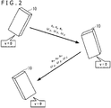
- FIG. 2 is a diagram for conceptually explaining a correction timing in the electronic apparatus depicted in FIG. 1 .
- the IMU 300 detects accelerations a x , a y , and a z and angular velocities ⁇ ⁇ , ⁇ ⁇ , and ⁇ ⁇ .
- the processing circuit 220 of the control section 200 estimates the attitude angle and displacement of the electronic apparatus 10 by integrating the accelerations and integrating the angular velocities, as previously explained. However, as a period of time for the integration becomes longer, errors (which are called drift errors, bias errors, or the like) included in the measurement result obtained by the IMU 300 are integrated.
- the control section 200 executes a process of correcting a measurement result from the IMU 300 or an estimated value based on the measurement result, according to the frequency of event signals received from the vision sensor 100. More specifically, for example, when the frequency of event signals is low, the control section 200 cancels a drift error or a bias error included in the measurement result. Alternatively, when the frequency of event signals is low, the control section 200 may eliminate an error component from estimated values of an attitude angle and displacement based on the measurement result. As previously explained, the vision sensor 100 is displaced together with the IMU 300, and when a displacement of the electronic apparatus 10 occurs, event signals corresponding to the displacement are generated in the vision sensor 100.
- the electronic apparatus 10 can be predicted to be in a standstill state during a period of time in which no event signal is generated by the vision sensor 100.
- the vision sensor 100 of the event-driven type is operated at higher speed than frame-type vision sensors, for example.
- the moment of the standstill can be identified by the above process, so that the measurement result or the estimated value can be corrected.
- the measurement result or the estimated value can be corrected at high frequency. This results in improvement in the measurement result itself and the accuracy of the estimation of the attitude angle and displacement of the electronic apparatus 10 by the control section 200.
- FIG. 3 is a block diagram depicting the functional configuration of a processing circuit of the electronic apparatus depicted in FIG. 1 .
- the processing circuit 220 of the control section 200 includes an event signal analysis section 221, a measurement result analysis section 222, a correction timing decision section 223, and a correction process section 224, which are functions implemented by being operated according to a program stored in the memory 230, for example.
- the event signal analysis section 221 analyzes event signals received from the vision sensor 100 via the communication interface 210. Specifically, the event signal analysis section 221 calculates the frequency of the event signals on the basis of time stamps included in the event signals, for example.
- the measurement result analysis section 222 analyzes a measurement result of an acceleration, an angular velocity, etc., received from the IMU 300 via the communication interface 210. Specifically, the measurement result analysis section 222 calculates estimated values 231 of the attitude angle and displacement by integrating the accelerations and integrating the angular velocities, for example. Time-series data concerning a measurement result 232 of the acceleration and angular velocity and the estimated values 231 is stored in the memory 230, for example.
- the correction timing decision section 223 decides a correction timing corresponding to a standstill state of the electronic apparatus 10, on the basis of the frequency of the event signals calculated by the event signal analysis section 221.
- the correction process section 224 executes a correction process of the measurement result 232 from the IMU 300 or the estimated values 231 based on the measurement result.
- the correction process section 224 identifies, as an error, a value corresponding to the difference between an actual measurement result and a theoretical measurement result, the theoretical measurement result being obtained during the standstill state of the electronic apparatus 10, specifically, during a state where both the angular velocity and an acceleration other than the gravity acceleration are zero.
- the correction process section 224 then gives such an offset as to cancel the error, to the measurement result 232 of the acceleration and angular velocity that is obtained by the IMU 300.
- the correction process section 224 may correct, on a real time basis, the measurement result 232 inputted to the measurement result analysis section 222 after the correction timing, or may afterwards correct a data acquired after the correction timing, the data being included in the time-series data of the measurement result 232 that has already been processed. In a case where the measurement result 232 is corrected afterwards, the measurement result analysis section 222 may calculate the estimated values 231 again.
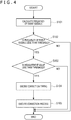
- FIG. 4 is a flowchart schematically illustrating an example of processes in the electronic apparatus depicted in FIG. 1 .
- the event signal analysis section 221 calculates the frequency of event signals (step S101).
- the event signal analysis section 221 may calculate the frequency while sequentially moving a time window, on the basis of the number of event signals received within the last predetermined period of time, for example.
- the event signal analysis section 221 may calculate the frequency for every predetermined cycle, on the basis of the number of event signals received in the last cycle.
- the correction timing decision section 223 determines whether or not the frequency of event signals calculated in step S101 is less than a threshold (step S102).
- the electronic apparatus 10 is determined to be not in a standstill state. Then, the process is finished.
- the correction timing decision section 223 may further determine whether or not a measurement value included in the measurement result from the IMU 300 is less than a threshold (step S103). In a case where the surrounding area of the electronic apparatus 10 is dark or where the angle of view of the sensor array 110 is shielded, for example, the electronic apparatus 10 may be not in a standstill state even if the frequency of event signals is low.
- the correction timing decision section 223 may decide the correction timing on condition that a detection value, specifically, the value of an acceleration or angular velocity included in the measurement result from the IMU 300 is less than the threshold and that movement of the electronic apparatus 10 is estimated to be small at a certain level.
- the correction timing decision section 223 decides a correction timing (step S104), and the correction process section 224 executes the correction process according to the correction timing (step S105).
- the correction process section 224 may correct, on a real time basis, the measurement result 232 inputted to the measurement result analysis section 222 after the correction timing, or may afterwards correct a data acquired after the correction timing, the data being included in the time-series data of the measurement result 232 that has already been processed.
- the measurement result analysis section 222 may execute a step (not illustrated) of calculating the estimated values 231 again.
- the correction process section 224 may correct the estimated values 231 that are based on the measurement result.
- the control section 200 executes a process of correcting the measurement result from the IMU 300 according to the frequency of event signals received from the vision sensor 100. Accordingly, for example, a time point at which the electronic apparatus 10 comes to a standstill can be precisely identified, and an error included in the measurement result can be canceled. Since the error can be cancelled at a higher frequency, the measurement result itself and the accuracy of the estimation of the attitude angle and displacement of the electronic apparatus 10 can be improved.
Landscapes
- Physics & Mathematics (AREA)
- General Physics & Mathematics (AREA)
- Spectroscopy & Molecular Physics (AREA)
- Gyroscopes (AREA)
- Indicating Or Recording The Presence, Absence, Or Direction Of Movement (AREA)
- Navigation (AREA)
- Studio Devices (AREA)
Abstract
Description
- The present invention relates to an electronic apparatus, a correction method, and a program.
- A vision sensor of an event-driven type in which pixels each having detected a change of an incident light intensity generate signals in a time asynchronous manner has been known. Such an event-driven vision sensor is advantageous in operating at high speed and with low power compared with a frame-type vision sensor which scans all the pixels for every predetermined cycle, the frame-type vision sensor being typified by an image sensor such as a CCD (Charge-Coupled Device) or a CMOS (Complementary Metal Oxide Semiconductor). For example, PTL 1 and PTL 2 disclose technologies related to such an event-driven vision sensor.
-
- [PTL 1]
JP-T-2014-535098 - [PTL 2]
JP 2018-85725A - The abovementioned advantageous effects of the event-driven vision sensor have been known; however, it is hard to say that peripheral technologies have sufficiently been proposed by taking characteristics of the event-driven vision sensor that are different from those of the conventional vision sensor such as the frame-type vision sensor, into consideration.
- Therefore, an object of the present invention is to provide an electronic apparatus, a correction method, and a program that can improve the accuracy of a measurement result from an IMU (Inertial Measurement Unit) or the accuracy of an estimated value based on the measurement result from the IMU by means of an event-driven vision sensor.
- According to one aspect of the present invention, provided is an electronic apparatus including a vision sensor of an event-driven type including a sensor array having a sensor that generates an event signal when detecting a change of an incident light intensity, an IMU that is displaced together with the vision sensor, and a correction process section that corrects a measurement result from the IMU or an estimated value based on the measurement result from the IMU, according to the frequency of the event signals.
- According to another aspect of the present invention, provided is a correction method including a step of receiving an event signal from a vision sensor of an event-driven type including a sensor array having a sensor that generates the event signal when detecting a change of an incident light intensity, a step of receiving a measurement result from an IMU that is displaced together with the vision sensor, and a step of correcting the measurement result from the IMU or an estimated value based on the measurement result from the IMU, according to the frequency of the event signals.
- According to still another aspect of the present invention, provided is a program causing a processing circuit included in a control section of an electronic apparatus to execute a step of receiving an event signal from a vision sensor of an event-driven type including a sensor array having a sensor that generates the event signal when detecting a change of an incident light intensity, a step of receiving a measurement result from an IMU that is displaced together with the vision sensor, and a step of correcting the measurement result from the IMU or an estimated value based on the measurement result from the IMU, according to the frequency of the event signals.
- According to the above configurations, a state in which the electronic apparatus is at a standstill can be determined from the frequency of the event signals, for example. Accordingly, the accuracy of the measurement result from the IMU or the accuracy of the estimated value based on the measurement result from the IMU can be improved by means of the vision sensor of the event-driven type.
-
- [
FIG. 1 ]
FIG. 1 is a block diagram schematically depicting the configuration of an electronic apparatus according to one embodiment of the present invention. - [
FIG. 2 ]
FIG. 2 is a diagram for conceptually explaining a correction timing in the electronic apparatus depicted inFIG. 1 . - [
FIG. 3 ]
FIG. 3 is a block diagram depicting the functional configuration of a processing circuit of the electronic apparatus depicted inFIG. 1 . - [
FIG. 4 ]
FIG. 4 is a flowchart schematically illustrating an example of processes in the electronic apparatus depicted inFIG. 1 . - Hereinafter, some embodiments of the present invention will be explained in detail with reference to the attached drawings.
- It is to be noted that components having substantially the same functional configuration are denoted by the same reference sign throughout the present description and the drawings and that an overlapping explanation thereof will be omitted.
-
FIG. 1 is a block diagram schematically depicting the configuration of an electronic apparatus including a sensor module according to a first embodiment of the present invention. As depicted inFIG. 1 , anelectronic apparatus 10 includes avision sensor 100, acontrol section 200, and an IMU 300. - The
vision sensor 100 of an event-driven type includes asensor array 110 that includessensors processing circuit 120 that is connected to thesensor array 110. Each of thesensors processing circuit 120, the event signals are outputted as information indicating, for example, a time stamp, sensor identification information (e.g., pixel position), and the polarity (increase or decrease) of a brightness change. When a subject moves within the angle of view of thesensor array 110, the intensity of light reflected or scattered by the subject changes. Therefore, movement of the subject can be detected on a time-series basis through the event signals generated by thesensors - The
control section 200 includes acommunication interface 210, aprocessing circuit 220, and amemory 230. Thecommunication interface 210 receives event signals transmitted from theprocessing circuit 120 of thevision sensor 100 and a measurement result of an acceleration, an angular velocity, etc., transmitted from theIMU 300 and outputs the event signals and the measurement result to theprocessing circuit 220. Theprocessing circuit 220 is operated according to a program stored in thememory 230, for example, and processes the received event signals and the received measurement result. For example, according to the event signals, theprocessing circuit 220 generates an image on which a position in which a brightness change has occurred is mapped, on the time-series basis, and temporarily or persistently stores the image in thememory 230 or transmits the image to another apparatus via thecommunication interface 210. In addition, for example, theprocessing circuit 220 estimates the attitude angle and displacement of theelectronic apparatus 10 by integrating the measurement results of the acceleration, the angular velocity, etc. - The IMU 300 includes a gyro sensor and an acceleration sensor, for example, to detect an angular velocity and an acceleration generated in the
electronic apparatus 10. Here, the IMU 300 is at least housed in the same casing as thevision sensor 100 in theelectronic apparatus 10 and is displaced together with thevision sensor 100. When a displacement of theelectronic apparatus 10 occurs, theIMU 300 detects the angular velocity and the acceleration. Further, the positional relation between thesensors sensors electronic apparatus 10 occurs, event signals corresponding to the displacement are generated in thevision sensor 100. -
FIG. 2 is a diagram for conceptually explaining a correction timing in the electronic apparatus depicted inFIG. 1 . When a translational and rotational displacement of theelectronic apparatus 10 occurs, theIMU 300 detects accelerations ax, ay, and az and angular velocities ωϕ, ωθ, and ωΨ. Theprocessing circuit 220 of thecontrol section 200 estimates the attitude angle and displacement of theelectronic apparatus 10 by integrating the accelerations and integrating the angular velocities, as previously explained. However, as a period of time for the integration becomes longer, errors (which are called drift errors, bias errors, or the like) included in the measurement result obtained by theIMU 300 are integrated. Accordingly, the accuracy of the estimation of the attitude angle and displacement is deteriorated. It is known that the acceleration and the angular velocity become zero at a timing when theelectronic apparatus 10 comes to a standstill (v = 0). Therefore, errors included in the measurement result can be canceled. However, it is not necessarily easy to identify, from the measurement result, the timing when theelectronic apparatus 10 comes to a standstill because an error is included in the measurement result itself obtained by theIMU 300, as previously explained. - Therefore, in the present embodiment, the
control section 200 executes a process of correcting a measurement result from theIMU 300 or an estimated value based on the measurement result, according to the frequency of event signals received from thevision sensor 100. More specifically, for example, when the frequency of event signals is low, thecontrol section 200 cancels a drift error or a bias error included in the measurement result. Alternatively, when the frequency of event signals is low, thecontrol section 200 may eliminate an error component from estimated values of an attitude angle and displacement based on the measurement result. As previously explained, thevision sensor 100 is displaced together with theIMU 300, and when a displacement of theelectronic apparatus 10 occurs, event signals corresponding to the displacement are generated in thevision sensor 100. In other words, theelectronic apparatus 10 can be predicted to be in a standstill state during a period of time in which no event signal is generated by thevision sensor 100. Thevision sensor 100 of the event-driven type is operated at higher speed than frame-type vision sensors, for example. Thus, even in a case where theelectronic apparatus 10 is momentarily at a standstill, the moment of the standstill can be identified by the above process, so that the measurement result or the estimated value can be corrected. Accordingly, the measurement result or the estimated value can be corrected at high frequency. This results in improvement in the measurement result itself and the accuracy of the estimation of the attitude angle and displacement of theelectronic apparatus 10 by thecontrol section 200. -
FIG. 3 is a block diagram depicting the functional configuration of a processing circuit of the electronic apparatus depicted inFIG. 1 . In the example depicted inFIG. 3 , theprocessing circuit 220 of thecontrol section 200 includes an eventsignal analysis section 221, a measurementresult analysis section 222, a correctiontiming decision section 223, and acorrection process section 224, which are functions implemented by being operated according to a program stored in thememory 230, for example. The eventsignal analysis section 221 analyzes event signals received from thevision sensor 100 via thecommunication interface 210. Specifically, the eventsignal analysis section 221 calculates the frequency of the event signals on the basis of time stamps included in the event signals, for example. Meanwhile, the measurementresult analysis section 222 analyzes a measurement result of an acceleration, an angular velocity, etc., received from theIMU 300 via thecommunication interface 210. Specifically, the measurementresult analysis section 222 calculates estimatedvalues 231 of the attitude angle and displacement by integrating the accelerations and integrating the angular velocities, for example. Time-series data concerning ameasurement result 232 of the acceleration and angular velocity and the estimatedvalues 231 is stored in thememory 230, for example. - The correction
timing decision section 223 decides a correction timing corresponding to a standstill state of theelectronic apparatus 10, on the basis of the frequency of the event signals calculated by the eventsignal analysis section 221. When the correction timing is decided by the correctiontiming decision section 223, thecorrection process section 224 executes a correction process of themeasurement result 232 from theIMU 300 or the estimatedvalues 231 based on the measurement result. Specifically, for example, thecorrection process section 224 identifies, as an error, a value corresponding to the difference between an actual measurement result and a theoretical measurement result, the theoretical measurement result being obtained during the standstill state of theelectronic apparatus 10, specifically, during a state where both the angular velocity and an acceleration other than the gravity acceleration are zero. Thecorrection process section 224 then gives such an offset as to cancel the error, to themeasurement result 232 of the acceleration and angular velocity that is obtained by theIMU 300. Thecorrection process section 224 may correct, on a real time basis, themeasurement result 232 inputted to the measurementresult analysis section 222 after the correction timing, or may afterwards correct a data acquired after the correction timing, the data being included in the time-series data of themeasurement result 232 that has already been processed. In a case where themeasurement result 232 is corrected afterwards, the measurementresult analysis section 222 may calculate the estimatedvalues 231 again. -
FIG. 4 is a flowchart schematically illustrating an example of processes in the electronic apparatus depicted inFIG. 1 . In the example illustrated inFIG. 4 , first, the eventsignal analysis section 221 calculates the frequency of event signals (step S101). Here, the eventsignal analysis section 221 may calculate the frequency while sequentially moving a time window, on the basis of the number of event signals received within the last predetermined period of time, for example. Alternatively, the eventsignal analysis section 221 may calculate the frequency for every predetermined cycle, on the basis of the number of event signals received in the last cycle. Next, the correctiontiming decision section 223 determines whether or not the frequency of event signals calculated in step S101 is less than a threshold (step S102). Here, in a case where the frequency is equal to or greater than the threshold, theelectronic apparatus 10 is determined to be not in a standstill state. Then, the process is finished. - On the other hand, in a case where the frequency of event signals is less than the threshold in step S102, the correction
timing decision section 223 may further determine whether or not a measurement value included in the measurement result from theIMU 300 is less than a threshold (step S103). In a case where the surrounding area of theelectronic apparatus 10 is dark or where the angle of view of thesensor array 110 is shielded, for example, theelectronic apparatus 10 may be not in a standstill state even if the frequency of event signals is low. In order to avoid performing correction of the measurement result or estimated value in such a case, the correctiontiming decision section 223 may decide the correction timing on condition that a detection value, specifically, the value of an acceleration or angular velocity included in the measurement result from theIMU 300 is less than the threshold and that movement of theelectronic apparatus 10 is estimated to be small at a certain level. - In a case where the detection value included in the measurement result from the
IMU 300 is less than the threshold in step S103, the correctiontiming decision section 223 decides a correction timing (step S104), and thecorrection process section 224 executes the correction process according to the correction timing (step S105). Specifically, thecorrection process section 224 may correct, on a real time basis, themeasurement result 232 inputted to the measurementresult analysis section 222 after the correction timing, or may afterwards correct a data acquired after the correction timing, the data being included in the time-series data of themeasurement result 232 that has already been processed. In a case where themeasurement result 232 is corrected afterwards, the measurementresult analysis section 222 may execute a step (not illustrated) of calculating the estimatedvalues 231 again. Alternatively, thecorrection process section 224 may correct the estimatedvalues 231 that are based on the measurement result. - In the first embodiment of the present invention explained so far, the
control section 200 executes a process of correcting the measurement result from theIMU 300 according to the frequency of event signals received from thevision sensor 100. Accordingly, for example, a time point at which theelectronic apparatus 10 comes to a standstill can be precisely identified, and an error included in the measurement result can be canceled. Since the error can be cancelled at a higher frequency, the measurement result itself and the accuracy of the estimation of the attitude angle and displacement of theelectronic apparatus 10 can be improved. - Some embodiments of the present invention have been explained in detail above with reference to the attached drawings. However, the present invention is not limited to these embodiments. It is clear that a person having the ordinary knowledge in the technical field to which the present invention belongs can conceive of various changes and modifications within the scope of the technical concept set forth in the claims. It should be understood that these changes and modifications are also within the technical scope of the present invention.
-
- 10:
- Electronic apparatus
- 100:
- Vision sensor
- 110:
- Sensor array
- 110A, 110B:
- Sensor
- 120:
- Processing circuit
- 200:
- Control section
- 210:
- Communication interface
- 220:
- Processing circuit
- 221:
- Event signal analysis section
- 222:
- Measurement result analysis section
- 223:
- Correction timing decision section
- 224:
- Correction process section
- 230:
- Memory
- 231:
- Estimated value
Claims (7)
- An electronic apparatus comprising:a vision sensor of an event-driven type including a sensor array having a sensor that generates an event signal when detecting a change of an incident light intensity;an inertial measurement unit that is displaced together with the vision sensor; anda correction process section that corrects a measurement result from the inertial measurement unit or an estimated value based on the measurement result from the inertial measurement unit, according to frequency of the event signals.
- The electronic apparatus according to claim 1, further comprising:a correction timing decision section that decides a correction timing corresponding to a standstill state of the electronic apparatus, on a basis of the frequency of the event signals, whereinthe correction process section corrects the measurement result from the inertial measurement unit or the estimated value when the correction timing is decided.
- The electronic apparatus according to claim 2, wherein the correction timing decision section decides the correction timing in a case where the frequency of the event signals is less than a threshold.
- The electronic apparatus according to claim 2 or 3, wherein the correction timing decision section decides the correction timing in a case where a detection value included in the measurement result from the inertial measurement unit is less than a threshold.
- The electronic apparatus according to any one of claims 1 to 4, whereinthe measurement result from the inertial measurement unit includes an angular velocity, andthe estimated value includes an attitude angle of the electronic apparatus.
- A correction method comprising:a step of receiving an event signal from a vision sensor of an event-driven type including a sensor array having a sensor that generates the event signal when detecting a change of an incident light intensity;a step of receiving a measurement result from an inertial measurement unit that is displaced together with the vision sensor; anda step of correcting the measurement result from the inertial measurement unit or an estimated value based on the measurement result from the inertial measurement unit, according to frequency of the event signals.
- A program causing a processing circuit included in a control section of an electronic apparatus to execute:a step of receiving an event signal from a vision sensor of an event-driven type including a sensor array having a sensor that generates the event signal when detecting a change of an incident light intensity;a step of receiving a measurement result from an inertial measurement unit that is displaced together with the vision sensor; anda step of correcting the measurement result from the inertial measurement unit or an estimated value based on the measurement result from the inertial measurement unit, according to frequency of the event signals.
Applications Claiming Priority (2)
| Application Number | Priority Date | Filing Date | Title |
|---|---|---|---|
| JP2018227780A JP7152285B2 (en) | 2018-12-05 | 2018-12-05 | Electronics, correction methods and programs |
| PCT/JP2019/047133 WO2020116417A1 (en) | 2018-12-05 | 2019-12-03 | Electronic device, correction method, and program |
Publications (3)
| Publication Number | Publication Date |
|---|---|
| EP3893004A1 true EP3893004A1 (en) | 2021-10-13 |
| EP3893004A4 EP3893004A4 (en) | 2022-08-24 |
| EP3893004B1 EP3893004B1 (en) | 2024-07-17 |
Family
ID=70975338
Family Applications (1)
| Application Number | Title | Priority Date | Filing Date |
|---|---|---|---|
| EP19892473.0A Active EP3893004B1 (en) | 2018-12-05 | 2019-12-03 | Electronic device, correction method, and program |
Country Status (6)
| Country | Link |
|---|---|
| US (1) | US12510404B2 (en) |
| EP (1) | EP3893004B1 (en) |
| JP (1) | JP7152285B2 (en) |
| KR (1) | KR102697610B1 (en) |
| CN (1) | CN113167810A (en) |
| WO (1) | WO2020116417A1 (en) |
Families Citing this family (2)
| Publication number | Priority date | Publication date | Assignee | Title |
|---|---|---|---|---|
| JP7618421B2 (en) * | 2020-11-09 | 2025-01-21 | キヤノン株式会社 | Information processing device, information processing method, and program |
| US20250150727A1 (en) * | 2022-01-28 | 2025-05-08 | Sony Interactive Entertainment Inc. | Electronic device, information processing method, and program |
Family Cites Families (13)
| Publication number | Priority date | Publication date | Assignee | Title |
|---|---|---|---|---|
| JP2002267685A (en) * | 2001-03-12 | 2002-09-18 | Canon Inc | Vibration detection device and image blur correction device |
| DE102011015457A1 (en) * | 2010-06-30 | 2012-01-05 | Wabco Gmbh | Method and device for detecting a vehicle movement |
| US8676498B2 (en) * | 2010-09-24 | 2014-03-18 | Honeywell International Inc. | Camera and inertial measurement unit integration with navigation data feedback for feature tracking |
| KR101880998B1 (en) * | 2011-10-14 | 2018-07-24 | 삼성전자주식회사 | Apparatus and Method for motion recognition with event base vision sensor |
| US9678102B2 (en) | 2011-11-04 | 2017-06-13 | Google Inc. | Calibrating intertial sensors using an image sensor |
| JP6222096B2 (en) | 2012-09-19 | 2017-11-01 | 株式会社ニコン | Electronic device and program |
| BR112017004321B1 (en) | 2014-09-05 | 2022-04-19 | Ethicon Llc | surgical instrument |
| JP2016125988A (en) * | 2015-01-08 | 2016-07-11 | 富士通株式会社 | Handheld terminal device and calibration method |
| WO2016154940A1 (en) * | 2015-03-31 | 2016-10-06 | SZ DJI Technology Co., Ltd. | Systems and methods for geo-fencing device identification and authentication |
| JP6325116B2 (en) * | 2015-05-23 | 2018-05-16 | エスゼット ディージェイアイ テクノロジー カンパニー リミテッドSz Dji Technology Co.,Ltd | Sensor fusion using inertial and image sensors |
| TWI730975B (en) | 2015-08-19 | 2021-06-21 | 日商半導體能源研究所股份有限公司 | Information processing device |
| US10260862B2 (en) * | 2015-11-02 | 2019-04-16 | Mitsubishi Electric Research Laboratories, Inc. | Pose estimation using sensors |
| US20180146149A1 (en) | 2016-11-21 | 2018-05-24 | Samsung Electronics Co., Ltd. | Event-based sensor, user device including the same, and operation method of the same |
-
2018
- 2018-12-05 JP JP2018227780A patent/JP7152285B2/en active Active
-
2019
- 2019-12-03 WO PCT/JP2019/047133 patent/WO2020116417A1/en not_active Ceased
- 2019-12-03 KR KR1020217015757A patent/KR102697610B1/en active Active
- 2019-12-03 CN CN201980078582.6A patent/CN113167810A/en active Pending
- 2019-12-03 US US17/296,843 patent/US12510404B2/en active Active
- 2019-12-03 EP EP19892473.0A patent/EP3893004B1/en active Active
Also Published As
| Publication number | Publication date |
|---|---|
| JP2020091163A (en) | 2020-06-11 |
| JP7152285B2 (en) | 2022-10-12 |
| KR102697610B1 (en) | 2024-08-23 |
| WO2020116417A1 (en) | 2020-06-11 |
| EP3893004A4 (en) | 2022-08-24 |
| KR20210083297A (en) | 2021-07-06 |
| CN113167810A (en) | 2021-07-23 |
| EP3893004B1 (en) | 2024-07-17 |
| US20220018710A1 (en) | 2022-01-20 |
| US12510404B2 (en) | 2025-12-30 |
Similar Documents
| Publication | Publication Date | Title |
|---|---|---|
| EP3645974B1 (en) | Method for compensating gyroscope drift on an electronic device | |
| EP2214403B1 (en) | Image processing device, photographing device, reproducing device, integrated circuit, and image processing method | |
| US20150146930A1 (en) | Image analysis apparatus mounted to vehicle | |
| US20150294453A1 (en) | Image analysis apparatus mounted to vehicle | |
| US11656242B2 (en) | Angular velocity detection device, image display apparatus, angular velocity detection method, and storage medium | |
| CN113739819B (en) | Verification method, verification device, electronic equipment, storage medium and chip | |
| KR102496300B1 (en) | Electronic device, actuator control method, and program | |
| EP3893004B1 (en) | Electronic device, correction method, and program | |
| US20220254165A1 (en) | Synchronization device, synchronization method, and non-transitory tangible computer readable storage medium | |
| US10309983B2 (en) | Systems and methods for motion detection | |
| EP3309767A1 (en) | Signaler detection device and signaler detection method | |
| CN111721305A (en) | Positioning method and apparatus, autonomous vehicle, electronic device and storage medium | |
| US12148210B2 (en) | Information processing method, information processing device, non-transitory computer-readable recording medium recording information processing program, and information processing system | |
| US20240085453A1 (en) | Method for evaluating sensor data, processing unit for evaluating sensor data, and sensor system | |
| JP5976027B2 (en) | Sensor axis deviation detection device and sensor axis deviation detection method | |
| US20170314923A1 (en) | Mems inertial sensor device with determination of the bias value of a gyroscope therof and corresponding method | |
| KR102392122B1 (en) | Mobile robot and its location estimation method | |
| CN111982179A (en) | Abnormality detection apparatus, abnormality detection method, and computer-readable medium | |
| US20250150727A1 (en) | Electronic device, information processing method, and program | |
| US20260025488A1 (en) | Control method and projection apparatus | |
| US20250274675A1 (en) | Signal processing circuit, signal processing method, and program | |
| KR20240074763A (en) | position correction device | |
| CN121619772A (en) | Component angle compensation method and system for machine vision guided component inserter | |
| CN121430673A (en) | Methods, devices, equipment, and storage media for calibrating the IMU mounting attitude. | |
| CN121323685A (en) | Methods, apparatus, devices, and products for generating odometry information for robots. |
Legal Events
| Date | Code | Title | Description |
|---|---|---|---|
| STAA | Information on the status of an ep patent application or granted ep patent |
Free format text: STATUS: THE INTERNATIONAL PUBLICATION HAS BEEN MADE |
|
| PUAI | Public reference made under article 153(3) epc to a published international application that has entered the european phase |
Free format text: ORIGINAL CODE: 0009012 |
|
| STAA | Information on the status of an ep patent application or granted ep patent |
Free format text: STATUS: REQUEST FOR EXAMINATION WAS MADE |
|
| 17P | Request for examination filed |
Effective date: 20210515 |
|
| AK | Designated contracting states |
Kind code of ref document: A1 Designated state(s): AL AT BE BG CH CY CZ DE DK EE ES FI FR GB GR HR HU IE IS IT LI LT LU LV MC MK MT NL NO PL PT RO RS SE SI SK SM TR |
|
| DAV | Request for validation of the european patent (deleted) | ||
| DAX | Request for extension of the european patent (deleted) | ||
| A4 | Supplementary search report drawn up and despatched |
Effective date: 20220727 |
|
| RIC1 | Information provided on ipc code assigned before grant |
Ipc: G01P 3/38 20060101ALN20220722BHEP Ipc: G01P 21/00 20060101AFI20220722BHEP |
|
| GRAP | Despatch of communication of intention to grant a patent |
Free format text: ORIGINAL CODE: EPIDOSNIGR1 |
|
| STAA | Information on the status of an ep patent application or granted ep patent |
Free format text: STATUS: GRANT OF PATENT IS INTENDED |
|
| RIC1 | Information provided on ipc code assigned before grant |
Ipc: G01P 3/38 20060101ALN20240208BHEP Ipc: G01P 21/00 20060101AFI20240208BHEP |
|
| INTG | Intention to grant announced |
Effective date: 20240220 |
|
| GRAS | Grant fee paid |
Free format text: ORIGINAL CODE: EPIDOSNIGR3 |
|
| GRAA | (expected) grant |
Free format text: ORIGINAL CODE: 0009210 |
|
| STAA | Information on the status of an ep patent application or granted ep patent |
Free format text: STATUS: THE PATENT HAS BEEN GRANTED |
|
| P01 | Opt-out of the competence of the unified patent court (upc) registered |
Effective date: 20240529 |
|
| AK | Designated contracting states |
Kind code of ref document: B1 Designated state(s): AL AT BE BG CH CY CZ DE DK EE ES FI FR GB GR HR HU IE IS IT LI LT LU LV MC MK MT NL NO PL PT RO RS SE SI SK SM TR |
|
| REG | Reference to a national code |
Ref country code: CH Ref legal event code: EP |
|
| REG | Reference to a national code |
Ref country code: DE Ref legal event code: R096 Ref document number: 602019055528 Country of ref document: DE |
|
| REG | Reference to a national code |
Ref country code: IE Ref legal event code: FG4D |
|
| REG | Reference to a national code |
Ref country code: NL Ref legal event code: FP |
|
| REG | Reference to a national code |
Ref country code: LT Ref legal event code: MG9D |
|
| PG25 | Lapsed in a contracting state [announced via postgrant information from national office to epo] |
Ref country code: PT Free format text: LAPSE BECAUSE OF FAILURE TO SUBMIT A TRANSLATION OF THE DESCRIPTION OR TO PAY THE FEE WITHIN THE PRESCRIBED TIME-LIMIT Effective date: 20241118 |
|
| REG | Reference to a national code |
Ref country code: AT Ref legal event code: MK05 Ref document number: 1704614 Country of ref document: AT Kind code of ref document: T Effective date: 20240717 |
|
| PG25 | Lapsed in a contracting state [announced via postgrant information from national office to epo] |
Ref country code: PT Free format text: LAPSE BECAUSE OF FAILURE TO SUBMIT A TRANSLATION OF THE DESCRIPTION OR TO PAY THE FEE WITHIN THE PRESCRIBED TIME-LIMIT Effective date: 20241118 |
|
| PG25 | Lapsed in a contracting state [announced via postgrant information from national office to epo] |
Ref country code: NO Free format text: LAPSE BECAUSE OF FAILURE TO SUBMIT A TRANSLATION OF THE DESCRIPTION OR TO PAY THE FEE WITHIN THE PRESCRIBED TIME-LIMIT Effective date: 20241017 |
|
| PG25 | Lapsed in a contracting state [announced via postgrant information from national office to epo] |
Ref country code: GR Free format text: LAPSE BECAUSE OF FAILURE TO SUBMIT A TRANSLATION OF THE DESCRIPTION OR TO PAY THE FEE WITHIN THE PRESCRIBED TIME-LIMIT Effective date: 20241018 Ref country code: FI Free format text: LAPSE BECAUSE OF FAILURE TO SUBMIT A TRANSLATION OF THE DESCRIPTION OR TO PAY THE FEE WITHIN THE PRESCRIBED TIME-LIMIT Effective date: 20240717 Ref country code: PL Free format text: LAPSE BECAUSE OF FAILURE TO SUBMIT A TRANSLATION OF THE DESCRIPTION OR TO PAY THE FEE WITHIN THE PRESCRIBED TIME-LIMIT Effective date: 20240717 |
|
| PG25 | Lapsed in a contracting state [announced via postgrant information from national office to epo] |
Ref country code: BG Free format text: LAPSE BECAUSE OF FAILURE TO SUBMIT A TRANSLATION OF THE DESCRIPTION OR TO PAY THE FEE WITHIN THE PRESCRIBED TIME-LIMIT Effective date: 20240717 |
|
| PG25 | Lapsed in a contracting state [announced via postgrant information from national office to epo] |
Ref country code: LV Free format text: LAPSE BECAUSE OF FAILURE TO SUBMIT A TRANSLATION OF THE DESCRIPTION OR TO PAY THE FEE WITHIN THE PRESCRIBED TIME-LIMIT Effective date: 20240717 |
|
| PG25 | Lapsed in a contracting state [announced via postgrant information from national office to epo] |
Ref country code: IS Free format text: LAPSE BECAUSE OF FAILURE TO SUBMIT A TRANSLATION OF THE DESCRIPTION OR TO PAY THE FEE WITHIN THE PRESCRIBED TIME-LIMIT Effective date: 20241117 Ref country code: AT Free format text: LAPSE BECAUSE OF FAILURE TO SUBMIT A TRANSLATION OF THE DESCRIPTION OR TO PAY THE FEE WITHIN THE PRESCRIBED TIME-LIMIT Effective date: 20240717 |
|
| PG25 | Lapsed in a contracting state [announced via postgrant information from national office to epo] |
Ref country code: HR Free format text: LAPSE BECAUSE OF FAILURE TO SUBMIT A TRANSLATION OF THE DESCRIPTION OR TO PAY THE FEE WITHIN THE PRESCRIBED TIME-LIMIT Effective date: 20240717 |
|
| PG25 | Lapsed in a contracting state [announced via postgrant information from national office to epo] |
Ref country code: RS Free format text: LAPSE BECAUSE OF FAILURE TO SUBMIT A TRANSLATION OF THE DESCRIPTION OR TO PAY THE FEE WITHIN THE PRESCRIBED TIME-LIMIT Effective date: 20241017 Ref country code: ES Free format text: LAPSE BECAUSE OF FAILURE TO SUBMIT A TRANSLATION OF THE DESCRIPTION OR TO PAY THE FEE WITHIN THE PRESCRIBED TIME-LIMIT Effective date: 20240717 |
|
| PG25 | Lapsed in a contracting state [announced via postgrant information from national office to epo] |
Ref country code: RS Free format text: LAPSE BECAUSE OF FAILURE TO SUBMIT A TRANSLATION OF THE DESCRIPTION OR TO PAY THE FEE WITHIN THE PRESCRIBED TIME-LIMIT Effective date: 20241017 Ref country code: PL Free format text: LAPSE BECAUSE OF FAILURE TO SUBMIT A TRANSLATION OF THE DESCRIPTION OR TO PAY THE FEE WITHIN THE PRESCRIBED TIME-LIMIT Effective date: 20240717 Ref country code: NO Free format text: LAPSE BECAUSE OF FAILURE TO SUBMIT A TRANSLATION OF THE DESCRIPTION OR TO PAY THE FEE WITHIN THE PRESCRIBED TIME-LIMIT Effective date: 20241017 Ref country code: LV Free format text: LAPSE BECAUSE OF FAILURE TO SUBMIT A TRANSLATION OF THE DESCRIPTION OR TO PAY THE FEE WITHIN THE PRESCRIBED TIME-LIMIT Effective date: 20240717 Ref country code: IS Free format text: LAPSE BECAUSE OF FAILURE TO SUBMIT A TRANSLATION OF THE DESCRIPTION OR TO PAY THE FEE WITHIN THE PRESCRIBED TIME-LIMIT Effective date: 20241117 Ref country code: HR Free format text: LAPSE BECAUSE OF FAILURE TO SUBMIT A TRANSLATION OF THE DESCRIPTION OR TO PAY THE FEE WITHIN THE PRESCRIBED TIME-LIMIT Effective date: 20240717 Ref country code: GR Free format text: LAPSE BECAUSE OF FAILURE TO SUBMIT A TRANSLATION OF THE DESCRIPTION OR TO PAY THE FEE WITHIN THE PRESCRIBED TIME-LIMIT Effective date: 20241018 Ref country code: FI Free format text: LAPSE BECAUSE OF FAILURE TO SUBMIT A TRANSLATION OF THE DESCRIPTION OR TO PAY THE FEE WITHIN THE PRESCRIBED TIME-LIMIT Effective date: 20240717 Ref country code: ES Free format text: LAPSE BECAUSE OF FAILURE TO SUBMIT A TRANSLATION OF THE DESCRIPTION OR TO PAY THE FEE WITHIN THE PRESCRIBED TIME-LIMIT Effective date: 20240717 Ref country code: BG Free format text: LAPSE BECAUSE OF FAILURE TO SUBMIT A TRANSLATION OF THE DESCRIPTION OR TO PAY THE FEE WITHIN THE PRESCRIBED TIME-LIMIT Effective date: 20240717 Ref country code: AT Free format text: LAPSE BECAUSE OF FAILURE TO SUBMIT A TRANSLATION OF THE DESCRIPTION OR TO PAY THE FEE WITHIN THE PRESCRIBED TIME-LIMIT Effective date: 20240717 |
|
| PG25 | Lapsed in a contracting state [announced via postgrant information from national office to epo] |
Ref country code: SM Free format text: LAPSE BECAUSE OF FAILURE TO SUBMIT A TRANSLATION OF THE DESCRIPTION OR TO PAY THE FEE WITHIN THE PRESCRIBED TIME-LIMIT Effective date: 20240717 Ref country code: DK Free format text: LAPSE BECAUSE OF FAILURE TO SUBMIT A TRANSLATION OF THE DESCRIPTION OR TO PAY THE FEE WITHIN THE PRESCRIBED TIME-LIMIT Effective date: 20240717 Ref country code: RO Free format text: LAPSE BECAUSE OF FAILURE TO SUBMIT A TRANSLATION OF THE DESCRIPTION OR TO PAY THE FEE WITHIN THE PRESCRIBED TIME-LIMIT Effective date: 20240717 |
|
| REG | Reference to a national code |
Ref country code: DE Ref legal event code: R097 Ref document number: 602019055528 Country of ref document: DE |
|
| PG25 | Lapsed in a contracting state [announced via postgrant information from national office to epo] |
Ref country code: EE Free format text: LAPSE BECAUSE OF FAILURE TO SUBMIT A TRANSLATION OF THE DESCRIPTION OR TO PAY THE FEE WITHIN THE PRESCRIBED TIME-LIMIT Effective date: 20240717 |
|
| PG25 | Lapsed in a contracting state [announced via postgrant information from national office to epo] |
Ref country code: CZ Free format text: LAPSE BECAUSE OF FAILURE TO SUBMIT A TRANSLATION OF THE DESCRIPTION OR TO PAY THE FEE WITHIN THE PRESCRIBED TIME-LIMIT Effective date: 20240717 |
|
| PG25 | Lapsed in a contracting state [announced via postgrant information from national office to epo] |
Ref country code: SK Free format text: LAPSE BECAUSE OF FAILURE TO SUBMIT A TRANSLATION OF THE DESCRIPTION OR TO PAY THE FEE WITHIN THE PRESCRIBED TIME-LIMIT Effective date: 20240717 |
|
| PLBE | No opposition filed within time limit |
Free format text: ORIGINAL CODE: 0009261 |
|
| STAA | Information on the status of an ep patent application or granted ep patent |
Free format text: STATUS: NO OPPOSITION FILED WITHIN TIME LIMIT |
|
| 26N | No opposition filed |
Effective date: 20250422 |
|
| PG25 | Lapsed in a contracting state [announced via postgrant information from national office to epo] |
Ref country code: MC Free format text: LAPSE BECAUSE OF FAILURE TO SUBMIT A TRANSLATION OF THE DESCRIPTION OR TO PAY THE FEE WITHIN THE PRESCRIBED TIME-LIMIT Effective date: 20240717 |
|
| REG | Reference to a national code |
Ref country code: CH Ref legal event code: PL |
|
| PG25 | Lapsed in a contracting state [announced via postgrant information from national office to epo] |
Ref country code: LU Free format text: LAPSE BECAUSE OF NON-PAYMENT OF DUE FEES Effective date: 20241203 |
|
| PG25 | Lapsed in a contracting state [announced via postgrant information from national office to epo] |
Ref country code: SE Free format text: LAPSE BECAUSE OF FAILURE TO SUBMIT A TRANSLATION OF THE DESCRIPTION OR TO PAY THE FEE WITHIN THE PRESCRIBED TIME-LIMIT Effective date: 20240717 |
|
| REG | Reference to a national code |
Ref country code: BE Ref legal event code: MM Effective date: 20241231 |
|
| PG25 | Lapsed in a contracting state [announced via postgrant information from national office to epo] |
Ref country code: BE Free format text: LAPSE BECAUSE OF NON-PAYMENT OF DUE FEES Effective date: 20241231 |
|
| PG25 | Lapsed in a contracting state [announced via postgrant information from national office to epo] |
Ref country code: CH Free format text: LAPSE BECAUSE OF NON-PAYMENT OF DUE FEES Effective date: 20241231 |
|
| PG25 | Lapsed in a contracting state [announced via postgrant information from national office to epo] |
Ref country code: IE Free format text: LAPSE BECAUSE OF NON-PAYMENT OF DUE FEES Effective date: 20241203 |
|
| PGFP | Annual fee paid to national office [announced via postgrant information from national office to epo] |
Ref country code: NL Payment date: 20251119 Year of fee payment: 7 |
|
| PGFP | Annual fee paid to national office [announced via postgrant information from national office to epo] |
Ref country code: DE Payment date: 20251126 Year of fee payment: 7 |
|
| PGFP | Annual fee paid to national office [announced via postgrant information from national office to epo] |
Ref country code: GB Payment date: 20251119 Year of fee payment: 7 |
|
| PGFP | Annual fee paid to national office [announced via postgrant information from national office to epo] |
Ref country code: FR Payment date: 20251120 Year of fee payment: 7 |
|
| PG25 | Lapsed in a contracting state [announced via postgrant information from national office to epo] |
Ref country code: IT Free format text: LAPSE BECAUSE OF FAILURE TO SUBMIT A TRANSLATION OF THE DESCRIPTION OR TO PAY THE FEE WITHIN THE PRESCRIBED TIME-LIMIT Effective date: 20240717 |
|
| PG25 | Lapsed in a contracting state [announced via postgrant information from national office to epo] |
Ref country code: CY Free format text: LAPSE BECAUSE OF FAILURE TO SUBMIT A TRANSLATION OF THE DESCRIPTION OR TO PAY THE FEE WITHIN THE PRESCRIBED TIME-LIMIT; INVALID AB INITIO Effective date: 20191203 |