EP3892975A1 - Strain sensor module - Google Patents
Strain sensor module Download PDFInfo
- Publication number
- EP3892975A1 EP3892975A1 EP21167528.5A EP21167528A EP3892975A1 EP 3892975 A1 EP3892975 A1 EP 3892975A1 EP 21167528 A EP21167528 A EP 21167528A EP 3892975 A1 EP3892975 A1 EP 3892975A1
- Authority
- EP
- European Patent Office
- Prior art keywords
- sensor
- base material
- strain
- electrodes
- sensor part
- Prior art date
- Legal status (The legal status is an assumption and is not a legal conclusion. Google has not performed a legal analysis and makes no representation as to the accuracy of the status listed.)
- Withdrawn
Links
- 239000000463 material Substances 0.000 claims abstract description 47
- 238000005259 measurement Methods 0.000 claims description 6
- 238000000034 method Methods 0.000 claims description 6
- 239000011347 resin Substances 0.000 claims description 2
- 229920005989 resin Polymers 0.000 claims description 2
- 238000001514 detection method Methods 0.000 description 7
- 230000035945 sensitivity Effects 0.000 description 5
- 238000011161 development Methods 0.000 description 4
- 238000010586 diagram Methods 0.000 description 4
- 238000012986 modification Methods 0.000 description 4
- 230000004048 modification Effects 0.000 description 4
- 230000000694 effects Effects 0.000 description 2
- 238000002432 robotic surgery Methods 0.000 description 2
- 239000000470 constituent Substances 0.000 description 1
- 238000013461 design Methods 0.000 description 1
- 230000002708 enhancing effect Effects 0.000 description 1
- 238000000206 photolithography Methods 0.000 description 1
- 238000004804 winding Methods 0.000 description 1
- 210000003857 wrist joint Anatomy 0.000 description 1
Images



Classifications
-
- G—PHYSICS
- G01—MEASURING; TESTING
- G01L—MEASURING FORCE, STRESS, TORQUE, WORK, MECHANICAL POWER, MECHANICAL EFFICIENCY, OR FLUID PRESSURE
- G01L1/00—Measuring force or stress, in general
- G01L1/20—Measuring force or stress, in general by measuring variations in ohmic resistance of solid materials or of electrically-conductive fluids; by making use of electrokinetic cells, i.e. liquid-containing cells wherein an electrical potential is produced or varied upon the application of stress
- G01L1/22—Measuring force or stress, in general by measuring variations in ohmic resistance of solid materials or of electrically-conductive fluids; by making use of electrokinetic cells, i.e. liquid-containing cells wherein an electrical potential is produced or varied upon the application of stress using resistance strain gauges
- G01L1/225—Measuring circuits therefor
- G01L1/2262—Measuring circuits therefor involving simple electrical bridges
-
- G—PHYSICS
- G01—MEASURING; TESTING
- G01L—MEASURING FORCE, STRESS, TORQUE, WORK, MECHANICAL POWER, MECHANICAL EFFICIENCY, OR FLUID PRESSURE
- G01L1/00—Measuring force or stress, in general
- G01L1/20—Measuring force or stress, in general by measuring variations in ohmic resistance of solid materials or of electrically-conductive fluids; by making use of electrokinetic cells, i.e. liquid-containing cells wherein an electrical potential is produced or varied upon the application of stress
- G01L1/22—Measuring force or stress, in general by measuring variations in ohmic resistance of solid materials or of electrically-conductive fluids; by making use of electrokinetic cells, i.e. liquid-containing cells wherein an electrical potential is produced or varied upon the application of stress using resistance strain gauges
- G01L1/2206—Special supports with preselected places to mount the resistance strain gauges; Mounting of supports
-
- G—PHYSICS
- G01—MEASURING; TESTING
- G01L—MEASURING FORCE, STRESS, TORQUE, WORK, MECHANICAL POWER, MECHANICAL EFFICIENCY, OR FLUID PRESSURE
- G01L1/00—Measuring force or stress, in general
- G01L1/20—Measuring force or stress, in general by measuring variations in ohmic resistance of solid materials or of electrically-conductive fluids; by making use of electrokinetic cells, i.e. liquid-containing cells wherein an electrical potential is produced or varied upon the application of stress
- G01L1/22—Measuring force or stress, in general by measuring variations in ohmic resistance of solid materials or of electrically-conductive fluids; by making use of electrokinetic cells, i.e. liquid-containing cells wherein an electrical potential is produced or varied upon the application of stress using resistance strain gauges
- G01L1/2287—Measuring force or stress, in general by measuring variations in ohmic resistance of solid materials or of electrically-conductive fluids; by making use of electrokinetic cells, i.e. liquid-containing cells wherein an electrical potential is produced or varied upon the application of stress using resistance strain gauges constructional details of the strain gauges
-
- H—ELECTRICITY
- H05—ELECTRIC TECHNIQUES NOT OTHERWISE PROVIDED FOR
- H05K—PRINTED CIRCUITS; CASINGS OR CONSTRUCTIONAL DETAILS OF ELECTRIC APPARATUS; MANUFACTURE OF ASSEMBLAGES OF ELECTRICAL COMPONENTS
- H05K1/00—Printed circuits
- H05K1/02—Details
-
- H—ELECTRICITY
- H05—ELECTRIC TECHNIQUES NOT OTHERWISE PROVIDED FOR
- H05K—PRINTED CIRCUITS; CASINGS OR CONSTRUCTIONAL DETAILS OF ELECTRIC APPARATUS; MANUFACTURE OF ASSEMBLAGES OF ELECTRICAL COMPONENTS
- H05K2201/00—Indexing scheme relating to printed circuits covered by H05K1/00
- H05K2201/10—Details of components or other objects attached to or integrated in a printed circuit board
- H05K2201/10007—Types of components
- H05K2201/10151—Sensor
Definitions
- the present invention relates to a strain sensor module.
- Patent Literature 1 discloses a modular type force sensor for enhancing sensitivity of force and torque and feedback to a surgeon who performs remote robotic surgery.
- Patent Literature 1 discloses a module type force sensor including a tube part containing a plurality of strain gauges, a proximal tube part to be operably coupled to a shaft of a surgical instrument that can be operably coupled to a manipulator arm of a robotic surgery system, and a distal tube part to be proximally connected to a wrist joint which is connected to a terminal part.
- an object of the present invention is to provide a strain sensor module capable of obtaining a large output with a simple structure.
- a strain sensor module comprises a base material, a sensor part, and a terminal part.
- the sensor part comprises a plurality of sensor electrodes for detecting strain formed on the base material, and a lead-out wiring for connecting the plurality of sensor electrodes in series.
- the terminal part is electrically connected to an external circuit.
- the strain sensor module 10 of the present embodiment comprises a base material 1, a sensor part 6, and a terminal part 7.
- the sensor part 6 comprises a plurality of sensor electrodes 2-1, 2-2, 2-3, 3-1, 3-2 and 3-3 for detecting a strain formed on the base material 1, and lead-out wirings 4 for connecting the sensor electrodes 2-1, 2-2 and 2-3 in series and connecting the sensor electrodes 3-1, 3-2 and 3-3 in series.
- the sensor electrodes 2-1, 2-2, 2-3, 3-1, 3-2, and 3-3 and the lead-out wirings 4 may be formed by a printing method or by a photolithography method or the like.
- the lead-out wirings 4 are connected to the terminal part 7.
- the terminal part 7 is electrically connected to an external circuit. Note that the number of sensor electrodes is not limited to the example shown in Fig. 1 , and may be any number as long as it is two or more.
- the strain sensor module 10 of the present embodiment is characterized in that the sensor electrodes are connected to one another in series to form a single large sensor electrode (sensor electrode group).
- the deformation direction of the sensor electrodes arranged on the same surface is always constant, so that it is unnecessary to consider a phenomenon that the distortion direction is different from one sensor electrode to another and thus the output is subjected to subtraction.
- the strain sensor module 10 of the embodiment since the sensor electrodes of each sensor electrode group are connected in series, the number of detection circuits in the subsequent stage can be set to one for each sensor electrode group, so that the circuit scale can be reduced.
- the base material 1 may be, for example, a resin film. A material having flexibility and elasticity is suitably used as the base material 1.
- the plurality of sensor electrodes 2-1, 2-2, 2-3, 3-1, 3-2, and 3-3 are formed in a row on the base material 1.
- the plurality of sensor electrodes 2-1, 2-2, and 2-3 are arranged in a row
- the plurality of sensor electrodes 3-1, 3-2, and 3-3 are arranged in a row so as to form another row.
- Slits 5 are formed between adjacent sensor electrodes on the base material (for example, between the sensor electrodes 2-1 and 2-2, between the sensor electrodes 2-2 and 2-3, between the sensor electrodes 3-1 and 3-2, and between the sensor electrodes 3-2 and 3-3).
- the strain sensor module 10 by winding the strain sensor module 10 around the steering wheel of an automobile, the pressure on the entire circumference of the steering wheel can be detected.
- the strain sensor module 10 is covered with a steering cover 8 of the steering wheel. Provision of the slits 5 enhances the flexibility (softness) of the base material 1 when the base material 1 is curved and shaped along the curved surface of the steering wheel.
- all the sensor electrode groups are arranged only on a surface (front surface) side of the base material 1 on which the base material 1 is gripped, so that the signs of resistance changes of all the sensor electrode groups under gripping pressure detection are coincident with one another, and thus the output of each sensor does not cancel the output of another sensor. The same effect can be obtained even when all the sensor electrode groups are arranged on a surface (back surface) side opposite to the surface side on which the base material 1 is gripped.
- the sensor electrodes 2-1, 2-2, 2-3, 3-1, 3-2, and 3-3 are arranged on only one side (front surface) of the base material 1.
- the base material 1 is folded along a broken line in Fig. 1 , and the back surfaces of the folded base material 1 are fixed to each other to form a double-sided electrode structure, whereby electrodes having the same thermal history can be formed on the front and back surfaces.
- the sensor electrode groups may be configured in advance on both the front and back surfaces of the base material 1.
- the sign of the resistance change is opposite between the sensor electrodes arranged on the front surface and the sensor electrodes arranged on the back surface.
- the sensor electrode group formed on the front surface of the base material 1 is referred to as a first sensor part 6-1 and the sensor electrode group formed on the back surface of the base material 1 is referred to as a second sensor part 6-2
- both the first sensor part 6-1 and the second sensor part 6-2 are used as gauges for measurement, and the first sensor part 6-1 is represented by R1 in Fig. 3 while the second sensor part 6-2 is represented by R3 in Fig.
- the strain sensor module 10 may be configured as a half-bridge circuit based on a 2-active gauge method.
- gripping a measurement target object causes constriction in the first sensor part 6-1 formed on the front surface of the base material 1, and also causes extension in the second sensor part 6-2 formed on the back surface of the base material 1.
- resistance changes in opposite directions occur, so that a bridge voltage E becomes large, and detection sensitivity is enhanced.
- the strain sensor module 10 may be a full-bridge circuit based on a 4-gauge method.
- gripping a measurement target object causes constriction in the third sensor part 6-3 formed on the front surface of the base material 1, and also causes extension in the fourth sensor part 6-4 formed on the back surface of the base material 1.
- resistance changes in opposite directions occur, so that a bridge voltage E becomes large, and detection sensitivity is enhanced.
- the sensor electrodes arranged on both the surfaces of the base material 1 are arranged at positions where the sensor electrodes overlap each other in a plan view of the base material.
- a strain occurs in the base material 1 such that the base material 1 is distorted into a wavy shape
- the sign of resistance change is not opposite between the electrodes arranged on the front surface and the electrodes arranged on the back surface.
- this phenomenon can be prevented, and the sign of resistance change is always opposite between the front surface and the back surface, and the detection sensitivity is enhanced.
- a heater, an electrostatic sensor, a biological sensor or the like may be mounted in the strain sensor module 10.
- General objects to be gripped such as the steering wheel of an automobile, an operation device such as a game controller or a mouse, a steering wheel, and a grip are assumed as objects in which the strain sensor module 10 of the embodiment is deployed.
- the respective sensor electrodes 2-1, 2-2, and 2-3 are arranged in a row along a longitudinal direction, and the slit 5 is formed between the adjacent sensor electrodes (between the sensor electrodes 2-1 and 2-2 in Fig. 4 and between the sensor electrodes 2-2 and 2-3 in Fig. 4 ).
- a plurality of sensor electrodes 2 may be arranged on a base material formed as a development view of a sphere in order to attach the strain sensor module to an operation device having a sphere-shaped grip part.
- the development view of Fig. 5 is a development view of a sphere, but by using an upper half or a lower half of the development view, the strain sensor module can also be attached to an operation device with a grip part having a hemispherical (dome-like) shape.
Landscapes
- Physics & Mathematics (AREA)
- General Physics & Mathematics (AREA)
- Engineering & Computer Science (AREA)
- Microelectronics & Electronic Packaging (AREA)
- Measurement Of Length, Angles, Or The Like Using Electric Or Magnetic Means (AREA)
Abstract
A strain sensor module comprises a base material, a sensor part including a plurality of sensor electrodes for detecting a strain formed on the base material and a lead-out wiring for connecting the plurality of sensor electrodes in series, and a terminal part which is electrically connected to an external circuit.
Description
- The present invention relates to a strain sensor module.
- Japanese Registered Patent No.
5431527 Patent Literature 1") discloses a modular type force sensor for enhancing sensitivity of force and torque and feedback to a surgeon who performs remote robotic surgery. - One embodiment of
Patent Literature 1 discloses a module type force sensor including a tube part containing a plurality of strain gauges, a proximal tube part to be operably coupled to a shaft of a surgical instrument that can be operably coupled to a manipulator arm of a robotic surgery system, and a distal tube part to be proximally connected to a wrist joint which is connected to a terminal part. - When attempt is made to detect a load or a stress by using an existing strain sensor, it is common practice to adopt such a manner of using a beam structure and attaching a strain sensor (generally, of a small size) to a point where a beam strain is concentrated. However, this also requires a housing design that allows a beam to sag, and places a limitation on a location where the sensor can be installed. For example, there is no room to introduce a beam structure into automobile steering.
- Therefore, an object of the present invention is to provide a strain sensor module capable of obtaining a large output with a simple structure.
- A strain sensor module according to the present invention comprises a base material, a sensor part, and a terminal part.
- The sensor part comprises a plurality of sensor electrodes for detecting strain formed on the base material, and a lead-out wiring for connecting the plurality of sensor electrodes in series. The terminal part is electrically connected to an external circuit.
- According to the strain sensor module of the present invention, a large output can be obtained with a simple structure.
-
-
Fig. 1 is a schematic diagram of a strain sensor module of a first embodiment; -
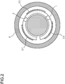
Fig. 2 is a schematic cross-sectional view of the strain sensor module installed in a steering wheel; -
Fig. 3 is a diagram illustrating a circuit configuration when a bridge circuit including sensor electrodes is configured; -
Fig. 4 is a schematic diagram of a strain sensor module of a first modification; and -
Fig. 5 is a schematic diagram of a strain sensor module of a second modification. - Hereinafter, embodiments of the present invention will be described in detail. Note that constituent parts having the same functions are designated by the same reference numbers, and duplicate description thereof will be omitted.
- Hereinafter, a configuration of a strain sensor module of a first embodiment will be described with reference to
Fig. 1 . As shown inFig. 1 , thestrain sensor module 10 of the present embodiment comprises abase material 1, asensor part 6, and aterminal part 7. - The
sensor part 6 comprises a plurality of sensor electrodes 2-1, 2-2, 2-3, 3-1, 3-2 and 3-3 for detecting a strain formed on thebase material 1, and lead-out wirings 4 for connecting the sensor electrodes 2-1, 2-2 and 2-3 in series and connecting the sensor electrodes 3-1, 3-2 and 3-3 in series. The sensor electrodes 2-1, 2-2, 2-3, 3-1, 3-2, and 3-3 and the lead-outwirings 4 may be formed by a printing method or by a photolithography method or the like. The lead-outwirings 4 are connected to theterminal part 7. Theterminal part 7 is electrically connected to an external circuit. Note that the number of sensor electrodes is not limited to the example shown inFig. 1 , and may be any number as long as it is two or more. Further, in the example ofFig. 1 , two series circuits (a series circuit including the sensor electrodes 2-1, 2-2, and 2-3 and a series circuit including the sensor electrodes 3-1, 3-2, and 3-3) are provided, but the number of the series circuits may be any number of one or more. Thestrain sensor module 10 of the present embodiment is characterized in that the sensor electrodes are connected to one another in series to form a single large sensor electrode (sensor electrode group). In the case of gripping pressure detection, the deformation direction of the sensor electrodes arranged on the same surface is always constant, so that it is unnecessary to consider a phenomenon that the distortion direction is different from one sensor electrode to another and thus the output is subjected to subtraction. Therefore, by connecting the sensor electrodes in series, resistance changes of the respective sensor electrodes can be added up, and detection sensitivity is enhanced. Further, in thestrain sensor module 10 of the embodiment, since the sensor electrodes of each sensor electrode group are connected in series, the number of detection circuits in the subsequent stage can be set to one for each sensor electrode group, so that the circuit scale can be reduced. - The
base material 1 may be, for example, a resin film. A material having flexibility and elasticity is suitably used as thebase material 1. - As shown in
Fig. 1 , it is preferable that the plurality of sensor electrodes 2-1, 2-2, 2-3, 3-1, 3-2, and 3-3 are formed in a row on thebase material 1. In the example ofFig. 1 , the plurality of sensor electrodes 2-1, 2-2, and 2-3 are arranged in a row, and the plurality of sensor electrodes 3-1, 3-2, and 3-3 are arranged in a row so as to form another row.Slits 5 are formed between adjacent sensor electrodes on the base material (for example, between the sensor electrodes 2-1 and 2-2, between the sensor electrodes 2-2 and 2-3, between the sensor electrodes 3-1 and 3-2, and between the sensor electrodes 3-2 and 3-3). - For example, as shown in
Fig. 2 , by winding thestrain sensor module 10 around the steering wheel of an automobile, the pressure on the entire circumference of the steering wheel can be detected. In the example ofFig. 2 , thestrain sensor module 10 is covered with asteering cover 8 of the steering wheel. Provision of theslits 5 enhances the flexibility (softness) of thebase material 1 when thebase material 1 is curved and shaped along the curved surface of the steering wheel. Further, all the sensor electrode groups are arranged only on a surface (front surface) side of thebase material 1 on which thebase material 1 is gripped, so that the signs of resistance changes of all the sensor electrode groups under gripping pressure detection are coincident with one another, and thus the output of each sensor does not cancel the output of another sensor. The same effect can be obtained even when all the sensor electrode groups are arranged on a surface (back surface) side opposite to the surface side on which thebase material 1 is gripped. - As shown in
Fig. 2 , the sensor electrodes 2-1, 2-2, 2-3, 3-1, 3-2, and 3-3 are arranged on only one side (front surface) of thebase material 1. However, thebase material 1 is folded along a broken line inFig. 1 , and the back surfaces of the foldedbase material 1 are fixed to each other to form a double-sided electrode structure, whereby electrodes having the same thermal history can be formed on the front and back surfaces. - Not limited to the folding example as described above, the sensor electrode groups may be configured in advance on both the front and back surfaces of the
base material 1. As a result, the sign of the resistance change is opposite between the sensor electrodes arranged on the front surface and the sensor electrodes arranged on the back surface. When the sensor electrode group formed on the front surface of thebase material 1 is referred to as a first sensor part 6-1 and the sensor electrode group formed on the back surface of thebase material 1 is referred to as a second sensor part 6-2, both the first sensor part 6-1 and the second sensor part 6-2 are used as gauges for measurement, and the first sensor part 6-1 is represented by R1 inFig. 3 while the second sensor part 6-2 is represented by R3 inFig. 3 , whereby thestrain sensor module 10 may be configured as a half-bridge circuit based on a 2-active gauge method. In this case, gripping a measurement target object causes constriction in the first sensor part 6-1 formed on the front surface of thebase material 1, and also causes extension in the second sensor part 6-2 formed on the back surface of thebase material 1. As a result, resistance changes in opposite directions occur, so that a bridge voltage E becomes large, and detection sensitivity is enhanced. - Further, when the sensor electrode group formed on the front surface of the
base material 1 is referred to as a third sensor part 6-3, and the sensor electrode group formed on the back surface of thebase material 1 is referred to as a fourth sensor part 6-4, both the third sensor part 6-3 and the fourth sensor part 6-4 are used as gauges for measurement, and the third sensor part 6-3 is represented by R2 inFig. 3 while the fourth sensor part 6-4 is represented by R4 inFig. 3 , whereby thestrain sensor module 10 may be a full-bridge circuit based on a 4-gauge method. In this case, gripping a measurement target object causes constriction in the third sensor part 6-3 formed on the front surface of thebase material 1, and also causes extension in the fourth sensor part 6-4 formed on the back surface of thebase material 1. As a result, resistance changes in opposite directions occur, so that a bridge voltage E becomes large, and detection sensitivity is enhanced. - Further, it is preferable that the sensor electrodes arranged on both the surfaces of the
base material 1 are arranged at positions where the sensor electrodes overlap each other in a plan view of the base material. When a strain occurs in thebase material 1 such that thebase material 1 is distorted into a wavy shape, there occurs a case in which the sign of resistance change is not opposite between the electrodes arranged on the front surface and the electrodes arranged on the back surface. However, by arranging these electrodes at the overlapping positions in a plan view of the base material, this phenomenon can be prevented, and the sign of resistance change is always opposite between the front surface and the back surface, and the detection sensitivity is enhanced. - Here, a heater, an electrostatic sensor, a biological sensor or the like may be mounted in the
strain sensor module 10. General objects to be gripped such as the steering wheel of an automobile, an operation device such as a game controller or a mouse, a steering wheel, and a grip are assumed as objects in which thestrain sensor module 10 of the embodiment is deployed. - As shown in
Fig. 4 , the respective sensor electrodes 2-1, 2-2, and 2-3 are arranged in a row along a longitudinal direction, and theslit 5 is formed between the adjacent sensor electrodes (between the sensor electrodes 2-1 and 2-2 inFig. 4 and between the sensor electrodes 2-2 and 2-3 inFig. 4 ). - As shown in
Fig. 5 , a plurality ofsensor electrodes 2 may be arranged on a base material formed as a development view of a sphere in order to attach the strain sensor module to an operation device having a sphere-shaped grip part. The development view ofFig. 5 is a development view of a sphere, but by using an upper half or a lower half of the development view, the strain sensor module can also be attached to an operation device with a grip part having a hemispherical (dome-like) shape.
Claims (7)
- A strain sensor module comprising
a base material;
a sensor part including a plurality of sensor electrodes for detecting a strain formed on the base material, and a lead-out wiring for connecting the plurality of sensor electrodes in series; and
a terminal part that is electrically connected to an external circuit. - The strain sensor module according to claim 1, wherein the plurality of sensor electrodes are formed in a row on the base material, and a slit is formed between adjacent sensor electrodes on the base material.
- The strain sensor module according to claim 1 or 2, further comprising a first sensor part which is the sensor part formed on a front surface of the base material, and a second sensor part which is the sensor part formed on a back surface of the base material, wherein a half-bridge circuit is formed, the half-bridge circuit being based on a 2-active gauge method in which both the first sensor part and the second sensor part are used as gauges for measurement.
- The strain sensor module according to claim 3, comprising a third sensor part which is the sensor part formed on a front surface of the base material, and a fourth sensor part which is the sensor part formed on a back surface of the base material, wherein a full-bridge circuit is formed, the full-bridge circuit being based on a 4-gauge method in which both the third sensor part and the fourth sensor part are also used as gauges for measurement.
- The strain sensor module according to claim 1 or 2, wherein a double-sided electrode structure is formed by folding the base material and fixing back surfaces of the folded base material to each other.
- The strain sensor module according to any one of claims 3 to 5, wherein the sensor electrodes arranged on both surfaces of the base material are arranged at positions where the sensor electrodes overlap each other in a plan view of the base material.
- The strain sensor module according to any one of claims 1 to 6, wherein the base material is a resin film.
Applications Claiming Priority (1)
| Application Number | Priority Date | Filing Date | Title |
|---|---|---|---|
| JP2020070787A JP2021167750A (en) | 2020-04-10 | 2020-04-10 | Strain sensor module |
Publications (1)
| Publication Number | Publication Date |
|---|---|
| EP3892975A1 true EP3892975A1 (en) | 2021-10-13 |
Family
ID=75441731
Family Applications (1)
| Application Number | Title | Priority Date | Filing Date |
|---|---|---|---|
| EP21167528.5A Withdrawn EP3892975A1 (en) | 2020-04-10 | 2021-04-08 | Strain sensor module |
Country Status (4)
| Country | Link |
|---|---|
| US (1) | US20210318190A1 (en) |
| EP (1) | EP3892975A1 (en) |
| JP (1) | JP2021167750A (en) |
| CN (1) | CN113514175A (en) |
Families Citing this family (1)
| Publication number | Priority date | Publication date | Assignee | Title |
|---|---|---|---|---|
| CN114593847A (en) * | 2022-03-24 | 2022-06-07 | 轻昂化学(深圳)有限公司 | Series connected flexible sensor structure |
Citations (5)
| Publication number | Priority date | Publication date | Assignee | Title |
|---|---|---|---|---|
| JPS5431527B2 (en) | 1975-11-07 | 1979-10-08 | ||
| US20150192482A1 (en) * | 2012-07-26 | 2015-07-09 | Murata Manufacturing Co., Ltd. | Pressing Force Sensor |
| US20170176167A1 (en) * | 2015-12-18 | 2017-06-22 | Oculus Vr, Llc | Embroidered strain sensing elements |
| WO2019131605A1 (en) * | 2017-12-28 | 2019-07-04 | ミネベアミツミ株式会社 | Strain gauge and sensor module |
| US20200073495A1 (en) * | 2018-09-04 | 2020-03-05 | Samsung Display Co., Ltd. | Electonic apparatus |
Family Cites Families (11)
| Publication number | Priority date | Publication date | Assignee | Title |
|---|---|---|---|---|
| JPS5215804Y2 (en) * | 1973-05-07 | 1977-04-09 | ||
| JPS5216746Y2 (en) * | 1973-10-15 | 1977-04-15 | ||
| JP3036262B2 (en) * | 1992-08-31 | 2000-04-24 | ヤマハ株式会社 | Bending sensor |
| JPH08292114A (en) * | 1995-04-24 | 1996-11-05 | Matsushita Refrig Co Ltd | Pressure sensor |
| JP3579380B2 (en) * | 2001-08-13 | 2004-10-20 | 株式会社山岸エーアイシー | Pressure sensor |
| JP2003083821A (en) * | 2001-09-13 | 2003-03-19 | Nec San-Ei Instruments Ltd | Non-inductive strain sensor and its measuring method |
| JP4234624B2 (en) * | 2003-03-14 | 2009-03-04 | ソニー株式会社 | Robot device |
| JP4936193B2 (en) * | 2008-06-24 | 2012-05-23 | パナソニック株式会社 | Load sensor |
| JP2012093199A (en) * | 2010-10-26 | 2012-05-17 | Railway Technical Research Institute | Method for measuring wheel load and lateral pressure, and wheel set for measuring wheel load and lateral pressure |
| JP2017150931A (en) * | 2016-02-24 | 2017-08-31 | 株式会社タニタ | Strain gauge |
| JP2017215203A (en) * | 2016-05-31 | 2017-12-07 | 株式会社フジクラ | Hold detector and pressure sensor |
-
2020
- 2020-04-10 JP JP2020070787A patent/JP2021167750A/en active Pending
-
2021
- 2021-04-06 US US17/223,368 patent/US20210318190A1/en not_active Abandoned
- 2021-04-08 CN CN202110376054.8A patent/CN113514175A/en active Pending
- 2021-04-08 EP EP21167528.5A patent/EP3892975A1/en not_active Withdrawn
Patent Citations (5)
| Publication number | Priority date | Publication date | Assignee | Title |
|---|---|---|---|---|
| JPS5431527B2 (en) | 1975-11-07 | 1979-10-08 | ||
| US20150192482A1 (en) * | 2012-07-26 | 2015-07-09 | Murata Manufacturing Co., Ltd. | Pressing Force Sensor |
| US20170176167A1 (en) * | 2015-12-18 | 2017-06-22 | Oculus Vr, Llc | Embroidered strain sensing elements |
| WO2019131605A1 (en) * | 2017-12-28 | 2019-07-04 | ミネベアミツミ株式会社 | Strain gauge and sensor module |
| US20200073495A1 (en) * | 2018-09-04 | 2020-03-05 | Samsung Display Co., Ltd. | Electonic apparatus |
Also Published As
| Publication number | Publication date |
|---|---|
| CN113514175A (en) | 2021-10-19 |
| JP2021167750A (en) | 2021-10-21 |
| US20210318190A1 (en) | 2021-10-14 |
Similar Documents
| Publication | Publication Date | Title |
|---|---|---|
| JP5008188B2 (en) | Triaxial force sensor and triaxial force detection method | |
| US7784363B2 (en) | Phalange tactile load cell | |
| JP2023052883A (en) | Surgical robot system and surgical instrument thereof | |
| US11788906B2 (en) | Force sensor | |
| JP2005106679A (en) | Multi-axis sensor unit and multi-axis sensor using the same | |
| JP4958501B2 (en) | Force sensor chip and external force transmission mechanism | |
| EP3892975A1 (en) | Strain sensor module | |
| JP5854143B2 (en) | Pressure sensor | |
| JP7396731B2 (en) | Multi-axis tactile sensor | |
| US11768118B2 (en) | Force sensor | |
| JP2019138741A (en) | Pressure sensor | |
| WO2018084284A1 (en) | Distribution measuring sensor, distribution measuring sensor system, distribution measuring program, and recording medium | |
| US20100000327A1 (en) | Strain gauge type sensor | |
| AU2020388742B2 (en) | Strain gauge, force sensor and interventional medical catheter | |
| Wolffenbuttel et al. | Compliant capacitive wrist sensor for use in industrial robots | |
| WO2024242293A1 (en) | Torque sensor module | |
| JP2007208427A (en) | Sensor module offset cancel circuit | |
| JP3546203B2 (en) | Strain gauge | |
| JP2018013339A (en) | Strain sensor, crack detection sensor and crack detection device | |
| JP2008116319A (en) | 3-axis force sensor | |
| CN116438424A (en) | Sensor strip and device for measuring geometry | |
| JP7781765B2 (en) | Torque and Force Transducers | |
| JPS63217241A (en) | Contact tactile sensor | |
| JP2002073262A (en) | Input status detection device | |
| CN114636489B (en) | A curved surface array tactile sensor and its working method and manipulator |
Legal Events
| Date | Code | Title | Description |
|---|---|---|---|
| PUAI | Public reference made under article 153(3) epc to a published international application that has entered the european phase |
Free format text: ORIGINAL CODE: 0009012 |
|
| STAA | Information on the status of an ep patent application or granted ep patent |
Free format text: STATUS: THE APPLICATION HAS BEEN PUBLISHED |
|
| AK | Designated contracting states |
Kind code of ref document: A1 Designated state(s): AL AT BE BG CH CY CZ DE DK EE ES FI FR GB GR HR HU IE IS IT LI LT LU LV MC MK MT NL NO PL PT RO RS SE SI SK SM TR |
|
| STAA | Information on the status of an ep patent application or granted ep patent |
Free format text: STATUS: THE APPLICATION IS DEEMED TO BE WITHDRAWN |
|
| 18D | Application deemed to be withdrawn |
Effective date: 20220414 |