EP3892933A1 - Air conditioner, indoor unit of air conditioner and rotating connection structure thereof - Google Patents
Air conditioner, indoor unit of air conditioner and rotating connection structure thereof Download PDFInfo
- Publication number
- EP3892933A1 EP3892933A1 EP19902121.3A EP19902121A EP3892933A1 EP 3892933 A1 EP3892933 A1 EP 3892933A1 EP 19902121 A EP19902121 A EP 19902121A EP 3892933 A1 EP3892933 A1 EP 3892933A1
- Authority
- EP
- European Patent Office
- Prior art keywords
- rotating
- rotating shaft
- groove
- elastic
- limiting
- Prior art date
- Legal status (The legal status is an assumption and is not a legal conclusion. Google has not performed a legal analysis and makes no representation as to the accuracy of the status listed.)
- Granted
Links
Images










Classifications
-
- F—MECHANICAL ENGINEERING; LIGHTING; HEATING; WEAPONS; BLASTING
- F24—HEATING; RANGES; VENTILATING
- F24F—AIR-CONDITIONING; AIR-HUMIDIFICATION; VENTILATION; USE OF AIR CURRENTS FOR SCREENING
- F24F1/00—Room units for air-conditioning, e.g. separate or self-contained units or units receiving primary air from a central station
- F24F1/0007—Indoor units, e.g. fan coil units
- F24F1/0043—Indoor units, e.g. fan coil units characterised by mounting arrangements
- F24F1/0047—Indoor units, e.g. fan coil units characterised by mounting arrangements mounted in the ceiling or at the ceiling
-
- F—MECHANICAL ENGINEERING; LIGHTING; HEATING; WEAPONS; BLASTING
- F24—HEATING; RANGES; VENTILATING
- F24F—AIR-CONDITIONING; AIR-HUMIDIFICATION; VENTILATION; USE OF AIR CURRENTS FOR SCREENING
- F24F1/00—Room units for air-conditioning, e.g. separate or self-contained units or units receiving primary air from a central station
- F24F1/0007—Indoor units, e.g. fan coil units
- F24F1/0071—Indoor units, e.g. fan coil units with means for purifying supplied air
- F24F1/0073—Indoor units, e.g. fan coil units with means for purifying supplied air characterised by the mounting or arrangement of filters
-
- F—MECHANICAL ENGINEERING; LIGHTING; HEATING; WEAPONS; BLASTING
- F24—HEATING; RANGES; VENTILATING
- F24F—AIR-CONDITIONING; AIR-HUMIDIFICATION; VENTILATION; USE OF AIR CURRENTS FOR SCREENING
- F24F13/00—Details common to, or for air-conditioning, air-humidification, ventilation or use of air currents for screening
- F24F13/28—Arrangement or mounting of filters
Definitions
- the present application relates to the field of air conditioner technologies, and particularly to an air conditioner, an indoor unit of the air conditioner and a rotating connection structure thereof.
- An indoor unit of an air conditioner is one of common household appliances, and a quality of life of people is improved by cooling and heating functions of the indoor unit of an air conditioner.
- a filter screen is required to be additionally mounted to prevent dust from entering the indoor unit of an air conditioner along with air flow, and after the filter screen is used for a long time, a thick layer of dust may adhere to the filter screen affecting air quality, and therefore, the filter screen is necessary to be frequently detached and cleaned.
- the filter screen is connected with a housing of the indoor unit of an air conditioner usually by forcibly clamping an elastic end into a round hole. To disassemble the filter screen from the housing of the indoor unit of an air conditioner, a technical person with professional skills must use professional disassembly tools to damage a connection structure of the filter screen and the housing.
- the present application is intended to provide a rotating connection structure and an indoor unit of an air conditioner, which aim at solving the technical problem that a connection structure between a filter screen and a housing of an indoor unit of an air conditioner is damaged during disassembly in the prior art.
- an embodiment of the present application provides a rotating connection structure, the rotating connection structure including a fixed member and a rotating member configured to rotate relative to the fixed member within a preset working angle range, a rotating shaft groove, a mounting groove and a limiting groove being defined on the fixed member, and the rotating member including a main body, a limiting member, a rotating shaft connected on the main body and a head connected to the rotating shaft; the head passing through the mounting groove such that the rotating shaft slides from the mounting groove into the rotating shaft groove, the rotating shaft being capable of rotating in the rotating shaft groove, the head being stopped outside the rotating shaft groove, and the head and the main body being located at two opposite sides of the fixed member; the limiting member being elastically deformed when the rotating shaft slides from the mounting groove to the rotating shaft groove, and recovering from the elastic deformation and being limited in the limiting groove when the rotating shaft slides into the rotating shaft groove, and a sliding range of the limiting member in the limiting groove including the preset working angle range of the rotating
- the rotating shaft groove, the mounting groove and the limiting groove are in communication with one another.
- the rotating shaft groove and the mounting groove are in communication with each other, and the limiting groove and the mounting groove are separately arranged independently.
- the limiting member includes an elastic sheet and a limiting protrusion
- the elastic sheet has a first end and a second end opposite to the first end
- the first end of the elastic sheet is connected to the main body of the rotating member
- the second end of the elastic sheet is configured as a free end
- the limiting protrusion is provided on the second end and limited in the limiting groove.
- the elastic sheet is elastically deformed in a direction away from the fixed member when the rotating shaft slides from the mounting groove towards the rotating shaft groove.
- the elastic sheet is vertically provided on the main body of the rotating member, and when the rotating shaft slides from the mounting groove towards the rotating shaft groove, the elastic sheet is elastically deformed in a direction opposite to the sliding direction of the rotating shaft.
- the rotating member further includes a positioning sheet connected to the main body, a positioning protrusion is provided on the positioning sheet, a positioning hole is defined on the fixed member, and the positioning protrusion is elastically inserted into the positioning hole when the rotating member and the fixed member have fixed relative positions.
- the positioning sheet has a first end and a second end opposite to the first end, the first end of the positioning sheet is connected to the main body of the rotating member, the second end of the positioning sheet is configured as a free end, and the positioning protrusion is provided on the second end.
- the positioning sheet is elastically deformed in a direction away from the fixed member when the rotating shaft slides from the mounting groove towards the rotating shaft groove.
- a first mounting portion is provided on the fixed member
- a second mounting portion is provided on the rotating member, and when the rotating member and the fixed member have fixed relative positions, the second mounting portion is connected on the first mounting portion.
- the main body has two opposite sides, a plurality of slots adapted to different flat plate members are defined in one side of the main body, the other side of the main body is rotatably connected on the fixed member, and an elastic member is provided on one side of each slot and elastically abuts against a flat plate member.
- the elastic member includes a connecting portion connected to a side portion of the slot and an elastic portion protruding and extending from the connecting portion towards an interior of the slot, and the elastic portion is separated from the side portion of the slot by the connecting portion.
- the main body includes a bottom plate, a top plate, and a side plate, the bottom plate is provided opposite to the top plate, the side plate has a bottom edge and a top edge opposite to the bottom edge, the bottom edge is connected with the bottom plate, the top edge is connected with the top plate, and the bottom plate and the top plate are enclosed to form one of the plurality of slots.
- the main body further includes a partition plate connected on the side plate, the bottom plate, the top plate and the partition plate form one of the plurality of slots, the partition plate and the bottom plate form another of the plurality of slots, and the partition plate and the top plate form a third one of the plurality of slots.
- the main body further includes a partition plate connected to the side plate and the bottom plate, the bottom plate, the top plate and the partition plate define one of the plurality of slots, and another of the plurality of slots is defined between the partition plate and the top plate.
- the bottom plate includes a first connected side edge and a first free side edge provided opposite to the first connected side edge, the first connected side edge is connected with the bottom edge, the partition plate includes a second connected side edge and a second free side edge provided opposite to the second connected side edge, the second connected side edge is connected with a side surface of the side plate, and a distance between the second free side edge and the side plate is less than a distance between the first free side edge and the side plate.
- the elastic members are provided on the top plate, the top plate has two opposite first lateral sides, the connecting portion is connected to one of the first lateral sides, the elastic portion has a third end and a fourth end opposite to the third end, the third end is connected with the connecting portion, and the fourth end is configured as a free end.
- the elastic members are provided on the bottom plate, the bottom plate has two opposite second lateral sides, the connecting portion is connected to one of the second lateral sides, the elastic portion has a third end and a fourth end opposite to the third end, the third end is connected with the connecting portion, and the fourth end is configured as a free end.
- the elastic members are provided at the top plate and the bottom plate respectively, the top plate has two opposite first lateral sides, the bottom plate has two opposite second lateral sides, and the elastic portion has a third end and a fourth end opposite to the third end; the connecting portion located on the top plate is connected to one of the first lateral sides, the third end located on the top plate is connected with the connecting portion located on the top plate, and the fourth end located on the top plate is configured as a free end; and the connecting portion located on the bottom plate is connected on one of the second lateral sides, the third end located on the bottom plate is connected with the connecting portion located on the bottom plate, and the fourth end located on the bottom plate is configured as a free end.
- the elastic members are provided on the top plate, the top plate has two opposite first lateral sides, each elastic member on the top plate includes the two connecting portions, one of the connecting portions is connected on one of the first lateral sides, the other one of the connecting portions is connected on the other one of the first lateral sides, the elastic portion has a third end and a fourth end opposite to the third end, the third end is connected with one of the connecting portions, and the fourth end is connected with the other one of the connecting portions.
- the elastic members are provided on the bottom plate, the bottom plate has two opposite second lateral sides, each elastic member on the bottom plate includes the two connecting portions, one of the connecting portions is connected on one of the second lateral sides, the other one of the connecting portions is connected to the other one of the second lateral sides, the elastic portion has a third end and a fourth end opposite to the third end, the third end is connected with one of the connecting portions, and the fourth end is connected with the other one of the connecting portions.
- the elastic members are provided at the top plate and the bottom plate respectively, the top plate has two opposite first lateral sides, the bottom plate has two opposite second lateral sides, and the elastic portion has a third end and a fourth end opposite to the third end; each elastic member located on the top plate includes the two connecting portions, one of the connecting portions located on the top plate is connected on one of the first lateral sides, the other one of the connecting portions located on the top plate is connected on the other one of the first lateral side, the third end located on the top plate is connected with one of the connecting portions located on the top plate, and the fourth end located on the top plate is connected with the other one of the connecting portions located on the top plate; and each elastic member located on the bottom plate includes the two connecting portions, one of the connecting portions located on the bottom plate is connected on one of the second lateral sides, the other one of the connecting portions located on the bottom plate is connected to the other one of the second lateral sides, the third end located on the bottom plate is connected with one of the connecting portions located on the bottom plate, and the fourth end located located
- a reinforcing rib configured to enhance a structural strength of the elastic member is provided on a side of the elastic portion away from the slot.
- a rotating connection is realized by inserting the head of the rotating shaft through the mounting groove, then sliding the head into the rotating shaft groove and limiting the limiting member in the limiting groove, and disassembly may be subsequently realized by pushing the limiting member out of the limiting groove, sliding the head of the rotating shaft back to the mounting groove and pushing the head out, such that the above-mentioned rotating connection structure is convenient to disassemble and assemble, may be disassembled and assembled repeatedly, and is not prone to damage, thus facilitating subsequent disassembly, assembly and maintenance.
- An embodiment of the present application provides an indoor unit of an air conditioner, including a filter assembly, a unit body, and a connecting mechanism connecting the filter assembly to the unit body; the connecting mechanism being configured as a rotating connection structure, and the rotating connection structure including a rotating member rotatably mounted at the unit body and a limiting member limiting rotation of the rotating member relative to the unit body to be within a preset working angle range; the filter assembly being mounted on the rotating member, the filter assembly rotating with rotation of the rotating member relative to the unit body, and the filter assembly being exposed outside the unit body after the rotating member rotates.
- a rotating shaft groove, a mounting groove and a limiting groove are defined on the unit body, and the rotating member includes a main body, a rotating shaft connected to the main body and a head connected to the rotating shaft; the head passes through the mounting groove such that the rotating shaft slides from the mounting groove into the rotating shaft groove, the rotating shaft is capable of rotating in the rotating shaft groove, and the head is stopped outside the rotating shaft groove; the limiting member is elastically deformed when the rotating shaft slides from the mounting groove towards the rotating shaft groove, and recovers from the elastic deformation and is limited in the limiting groove when the rotating shaft slides into the rotating shaft groove, and a sliding range of the limiting member in the limiting groove includes the preset working angle range of the rotating member.
- the rotating shaft groove, the mounting groove and the limiting groove are in communication with one another.
- the rotating shaft groove and the mounting groove are in communication with each other, and the limiting groove and the mounting groove are separately arranged independently.
- the limiting member includes an elastic sheet and a limiting protrusion
- the elastic sheet has a first end and a second end opposite to the first end
- the first end of the elastic sheet is connected to the main body of the rotating member
- the second end of the elastic sheet is configured as a free end
- the limiting protrusion is provided on the second end and is limited in the limiting groove.
- the unit body is provided with a mounting position for mounting the rotating member, and the elastic sheet is elastically deformed in a direction away from the mounting position when the rotating shaft slides from the mounting groove towards the rotating shaft groove.
- the elastic sheet is vertically provided on the main body of the rotating member, and when the rotating shaft slides from the mounting groove towards the rotating shaft groove, the elastic sheet is elastically deformed in a direction opposite to the sliding direction of the rotating shaft.
- the indoor unit of an air conditioner further includes a positioning sheet, a positioning protrusion is provided at the positioning sheet, a positioning hole is defined in the unit body, and the positioning protrusion is elastically inserted into the positioning hole when the rotating member and the unit body have fixed relative positions.
- the positioning sheet has a first end and a second end opposite to the first end, the first end of the positioning sheet is connected on the rotating member, the second end of the positioning sheet is configured as a free end, and the positioning protrusion is provided on the second end.
- the unit body is provided with a mounting position for mounting the rotating member, and the positioning sheet is elastically deformed in a direction away from the mounting position when the rotating shaft slides from the mounting groove to the rotating shaft groove.
- the filter assembly is inserted on the rotating member.
- the rotating member is provided with a wrench configured to rotate the rotating member, and the wrench is exposed outside the unit body.
- One or more technical solutions of the indoor unit of an air conditioner according to the embodiment of the present application have at least one of the following technical effects.
- the filter assembly is mounted in the rotating member in the above-mentioned rotating connection structure to achieve a rotating connection between the filter assembly and the unit body, such that the filter assembly may rotate along with the rotating connection structure, and the filter assembly may be conveniently and subsequently detached independently at any time to be cleaned and maintained, without damaging a connection structure between the filter assembly and the unit body.
- An embodiment of the present application provides an air conditioner, including the indoor unit of an air conditioner as mentioned above.
- the filter assembly is mounted in the rotating member in the above-mentioned rotating connection structure to achieve the rotating connection between the filter assembly and the unit body, such that the filter assembly may rotate along with the rotating connection structure, and the filter assembly may be conveniently and subsequently detached independently at any time to be cleaned and maintained, without damaging the connection structure between the filter assembly and the unit body.
- first and second are used herein for purposes of description and are not intended to indicate or imply relative importance or significance or to imply the number of indicated technical features.
- the feature defined with “first” and “second” may include one or more of this feature explicitly or implicitly.
- a plurality of' means two or more unless otherwise specified.
- the terms “mounted”, “connected”, “coupled”, and “fixed” and the like are used broadly, and may be, for example, fixed connections, detachable connections, or integral connections; may also be mechanical or electrical connections; may also be direct connections or indirect connections via intervening structures; may also be communication or an interaction relationship of two elements.
- the above terms can be understood by those skilled in the art according to specific situations.
- An embodiment of the present application provides a rotating connection structure, and the rotating connection structure is configured to realize a rotating connection between two components, and may be repeatedly disassembled and assembled without damage.
- the rotating connection structure includes a fixed member 11 and a rotating member 12 rotating relative to the fixed member 11 within a predetermined working angle range.
- the fixed member 11 is provided with a rotating shaft groove 111, a mounting groove 112 and a limiting groove 113. It should be noted here that the rotating shaft groove 111 and the mounting groove 112 are in communication with each other, and the mounting groove 112 should have a greater radial size than the rotating shaft groove 111; the limiting groove 113 is designed to have an arc shape, and radians spanned by the limiting groove 113 should be not less than the preset working angle range of the rotating member 12.
- the rotating shaft groove 111 and the mounting groove 112 provided in the fixed member 11 are configured to realize a connection with the rotating member 12, and the limiting groove 113 provided in the fixed member 11 is configured to limit slide and rotation of the rotating member 12.
- the rotating member 12 includes a main body 121, a limiting member 122, a rotating shaft 123 connected to the main body 121, and a head 124 connected to the rotating shaft 123.
- a rotating axis 123 of the rotating member 12 is located at a central axis of the rotating shaft 123 connected to the main body 121 of the rotating member 12;
- a center of the head 124 connected to the rotating shaft 123 should coincide with a center of the rotating shaft 123, such that the head 124 and the rotating shaft 123 are uniformly stressed after the rotating connection is realized;
- a radial size of the head 124 should be less than a radial size of the mounting groove 112 to enable the head 124 to pass through the mounting groove 112, and should be greater than a radial size of the rotating shaft groove 111 to enable the head 124 to be blocked outside the rotating shaft groove 111;
- a radial size of the rotating shaft 123 should be less than the radial size of the rotating shaft groove 111, such
- the head 124 passes through the mounting groove 112 and makes the rotating shaft 123 slide from the mounting groove 112 into the rotating shaft groove 111, the rotating shaft 123 may rotate in the rotating shaft groove 111, the head 124 is stopped outside the rotating shaft groove 111, and the head 124 and the main body 121 are located on two opposite sides of the fixed member 11; the limiting member 122 is elastically deformed when the rotating shaft 123 slides from the mounting groove 112 towards the rotating shaft groove 111, and recovers from the elastic deformation and is limited in the limiting groove 113 when the rotating shaft 123 slides into the rotating shaft groove 111, and a sliding range of the limiting member 122 in the limiting groove 113 includes the preset working angle range of the rotating member 12.
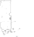
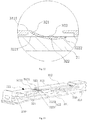
- the rotating shaft 123 when the rotating shaft 123 is slid from the mounting groove 112 towards the rotating shaft groove 111 and the limiting member 122 reaches the limiting groove 113, the limiting member 122 recovers from the elastic deformation and is limited in the limiting groove 113, and at this point, the rotating member 12 and the fixed member 11 may be mounted; specifically, referring to Fig. 12 , the rotating member 12 may rotate around the rotating shaft 123 within a range limited by the limiting groove 113.
- the limiting member 122 may be pushed out of the limiting groove 113 by elasticity of the limiting member 122 to release a limiting relationship, and then, the head 124 is withdrawn from the mounting groove 112 after the rotating shaft 123 of the rotating member 12 is slid back from the rotating shaft groove 111 to the mounting groove 112, so as to disassemble the rotating connection structure without damaging the rotating connection structure.
- the rotating connection is realized by inserting the head 124 of the rotating shaft 123 through the mounting groove 112, then sliding the head 124 into the rotating shaft groove 111 and limiting the limiting member 122 in the limiting groove 113, and the disassembly may be subsequently realized by pushing the limiting member 122 out of the limiting groove 113, sliding the head 124 of the rotating shaft 123 back to the mounting groove 112 and pushing the head 124 out, such that the rotating connection structure is convenient to disassemble and assemble, may be disassembled and assembled repeatedly, and is not prone to damage, thus facilitating subsequent disassembly, assembly and maintenance.
- the rotating shaft groove 111, the mounting groove 112 and the limiting groove 113 are in communication with one another.
- the limiting groove 113 is provided close to the mounting groove 112, the limiting groove 113 and the mounting groove 112 are in communication with each other, and an overall radial size of the limiting groove 113 and the mounting groove 112 should be greater than the radial size of the head 124 of the rotating shaft 123, such that the head 124 of the rotating shaft 123 passes through the mounting groove 112; the other side of the limiting groove 113 away from the side in communication with the mounting groove 112 should be disposed in an arc shape, and the radians spanned by the limiting groove 113 should be not less than the preset working angle range of the rotating member 12.
- the limiting member 122 and the rotating shaft 123 have a small center distance, and in the
- the rotating shaft groove 111 is in communication with the mounting groove 112, and the limiting groove 113 and the mounting groove 112 are separately disposed independently.
- the rotating shaft groove 111 is in communication with the mounting groove 112, so as to allow the head 124 of the rotating shaft 123 to pass through the mounting groove 112 and then slide into the rotating shaft groove 111, such that the head 124 of the rotating shaft 123 and the main body 121 of the rotating shaft 123 are located on two opposite sides of the fixed member 11 respectively;
- the limiting groove 113 and the mounting groove 112 are separately disposed independently, and the center distance between the limiting member 122 and the rotating shaft 123 should be within the range of the maximum distance between the limiting groove 113 and the rotating shaft groove 111, such that the limiting member 122 may be limited in the limiting groove 113 before the rotating shaft 123 slides to the end of the rotating shaft groove 111.
- the limiting member 122 includes an elastic sheet 1221 and a limiting protrusion 1222, the elastic sheet 1221 has a first end and a second end opposite to the first end, the first end of the elastic sheet 1221 is connected to the main body 121 of the rotating member 12, the second end of the elastic sheet 1221 is configured as a free end, and the limiting protrusion 1222 is provided at the second end and limited in the limiting groove 113.
- the elastic sheet 1221 is disposed transversely, and has one fixed end and the other free end, the limiting protrusion 1222 is provided at the free end, a part below the elastic sheet 1221 is hollowed to retain a space for the elastic sheet 1221 to generate elastic deformation, and the limiting member 122 has an elastic effect due to the elastic sheet 1221 and may be elastically deformed.
- the elastic sheet 1221 is elastically deformed in a direction away from the fixed member 11 when the rotating shaft 123 slides from the mounting groove 112 towards the rotating shaft groove 111.
- the first end of the elastic sheet 1221 is connected to the main body 121 of the rotating member 12, the second end of the elastic sheet 1221 is configured as a free end, and the limiting protrusion 1222 is provided at the second end, such that when the rotating shaft 123 slides from the mounting groove 112 towards the rotating shaft groove 111 and the limiting member 122 does not yet reach the limiting groove 113, the second end of the elastic sheet 1221 is elastically deformed in the direction away from the fixed member 11, thereby minimizing friction between the limiting member 122 and the fixed member 11, avoiding abrasion at corresponding positions of the limiting member 122 and the fixed member 11, and prolonging service lives thereof; when the rotating shaft 123 slides from the mounting groove 112 towards the rotating shaft groove 111 and the limiting member 122 reaches the
- the elastic sheet 1221 is vertically provided at the main body 121 of the rotating member 12, and the elastic sheet 1221 is elastically deformed in a direction opposite to the sliding direction of the rotating shaft 123 when the rotating shaft 123 slides from the mounting groove 112 towards the rotating shaft groove 111.
- the elastic sheet 1221 is vertically provided at the main body 121 of the rotating member 12, one end of the elastic sheet 1221 is connected to the main body 121 of the rotating member 12, the other end of the elastic sheet 1221 is connected to the limiting protrusion 1222, and spaces are left on both sides of the elastic sheet 1221 that do not interfere with the elastic deformation of the elastic sheet 1221; specifically, when the rotating shaft 123 slides from the mounting groove 112 towards the rotating shaft groove 111 and the limiting member 122 does not yet reach the limiting groove 113, the second end of the elastic sheet 1221 is elastically deformed in the direction opposite to the sliding direction of the rotating shaft 123, thereby minimizing the friction between the limiting member 122 and the fixed member 11, avoiding the abrasion at the corresponding positions of the limiting member 122 and the fixed member 11, and prolonging the service lives thereof; when the rotating shaft 123 slides from the mounting groove 112 towards the rotating shaft groove 111 and the limiting member 122 reaches the limiting groove 113, under the elastic effect
- the rotating member 12 further includes a positioning sheet 125 connected to the main body 121, the positioning sheet 125 is provided with a positioning protrusion 1251, the fixed member 11 is provided with a positioning hole 114, and the positioning protrusion 1251 is elastically inserted into the positioning hole 114 when the rotating member 12 and the fixed member 11 have fixed relative positions.
- the rotating member 12 is provided with the positioning sheet 125, the positioning hole 114 with a size matched with a size of the positioning protrusion 1251 is formed in a corresponding position of the fixed member 11, when the rotating connection structure is not required to be rotated and the relative positions of the rotating member 12 and the fixed member 11 are necessary to be kept fixed, the positioning protrusion 1251 is elastically inserted into the positioning hole 114, and when the rotating connection structure is required to be rotated or disassembled, the positioning protrusion 1251 is elastically pushed out of the positioning hole 114 to release the fixed relationship.
- the positioning sheet 125 has a first end and a second end opposite to the first end, the first end of the positioning sheet 125 is connected to the main body 121 of the rotating member 12, the second end of the positioning sheet 125 is configured as a free end, and the positioning protrusion 1251 is provided at the second end.
- the positioning sheet 1221 is disposed transversely, and has one fixed end and the other free end, the positioning protrusion 1251 is provided at the free end, a part below the positioning sheet 1221 is hollowed to retain a space for the positioning sheet 1221 to generate elastic deformation, and the positioning sheet 125 has an elastic effect and may be elastically deformed.
- the positioning protrusion 1251 of the positioning sheet 125 is provided away from the limiting protrusion 1222 of the limiting member 122, so as to reduce a space of the main body 121 occupied by the positioning sheet 125 and the limiting member 122 to a certain extent.
- the positioning sheet 125 is elastically deformed in a direction away from the fixed member 11 when the rotating shaft 123 slides from the mounting groove 112 towards the rotating shaft groove 111.
- the second end of the positioning sheet 125 is elastically deformed in the direction away from the fixed member 11, thereby minimizing friction between the positioning sheet 125 and the fixed member 11, avoiding abrasion at corresponding positions of the positioning sheet 125 and the fixed member 11, and prolonging service lives thereof;
- the positioning sheet 125 may recover from the elastic deformation and be limited in the positioning hole 114, so as to fix the relative positions of the rotating member 12 and the fixed member 11.
- a first mounting portion 115 is provided at the fixed member 11
- a second mounting portion 126 is provided at the rotating member 12 and when the rotating member 12 and the fixed member 11 have fixed relative positions, the second mounting portion 126 is connected to the first mounting portion 115.
- the fixed member 11 is provided with the first mounting portion 115, and the first mounting portion 115 is provided on the side of the fixed member 11 opposite to a rotating end of the rotating member 12, and is recessed inwards, so as to leave a space engaged with the second mounting portion 126 of the rotating member 12;
- the rotating member 12 is provided with the second mounting portion 126 perpendicular to the main body 121 of the rotating member 12, and when the rotating member 12 and the fixed member 11 have fixed relative positions, the first mounting portion 115 is engaged with the second mounting portion 126; connecting holes are defined in corresponding positions of the first mounting portion 115 and the second mounting portion 126, and may be correspondingly connected by common mechanical means including, but not limited to, screws, so as to fixedly connect the rotating member 12 and the fixed member 11; when the rotating connection structure is required to be in a rotating or detaching state, the fixed connection relationship between the rotating member 12 and the fixed member 11 may be released by detaching the common mechanical means including, but not limited to, screws.
- the rotating member 12 may be configured to rotatably connect a flat plate member 21 (for example, a filter assembly 21 of an indoor unit of an air conditioner) to the fixed member 11 (for example, the fixed member 11 is configured as a unit body of the indoor unit of an air conditioner).
- the main body 121 has two opposite sides, a plurality of slots 3101 adapted to different flat plate members 21 are defined in one side of the main body 121, and the other side of the main body 121 is rotatably connected to the fixed member 11.
- An elastic member 320 is provided on one side of each slot 3101, and when the flat plate member is inserted into the slot 3101, the elastic member 320 is elastically deformed to elastically abut against the flat plate member 21, thereby fixing the flat plate member 21 to prevent the flat plate member 21 from being displaced or released.
- the rotating member 12 in the present application by defining the plurality of slots 3101 in one side of the main body 121, the rotating member 12 in the present application may be adapted to different flat plate members 21, and thus has higher compatibility, a wider application range, convenient use and a lower cost; the elastic member 320 is provided on one side of the slot 3101 in the present application, and the elastic member 320 may elastically abut against the flat plate member 21 by elastic deformation, so as to fix the flat plate member 21 to prevent the flat plate member 21 from being displaced or released, and make disassembly and assembly simple and convenient.
- the elastic member 320 includes a connecting portion 321 and an elastic portion 322, the connecting portion 321 is connected to a side portion of the slot 3101, the elastic portion 322 protrudes and extends from the connecting portion 321 to the interior of the slot 3101, and the elastic portion 322 is separated from the side portion of the slot 3101 by the connecting portion 321.
- the elastic portion 322 protrudes and extends from the connecting portion 321 to the interior of the slot 3101, such that when inserted into the slot 3101, the flat plate member 21 may press a protruding position of the elastic portion 322, thereby elastically deforming the elastic portion 322 to fix the flat plate member 21 in the slot 3101.
- the main body 121 includes a bottom plate 311, a top plate 312, and a side plate 313.
- the bottom plate 311 is provided opposite to the top plate 312, and the side plate 313 has a bottom edge 3131 and a top edge 3132 opposite to the bottom edge 3131.
- the bottom edge 3131 is connected with the bottom plate 311 and the top edge 3132 is connected with the top plate 312.
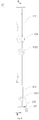
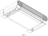
- One of the plurality of slots 3101 is defined between the bottom plate 311 and the top plate 312, and the flat plate member 21 may be inserted into the slot 3101, as shown in Fig. 11 .
- the bottom plate 311, the top plate 312 and the side plate 313 may be integrally formed and connected, such that connection reliability is high, the process is simple, and the processing operation is convenient.
- connection manner of the bottom plate, the top plate 312 and the side plate 313 is not limited to this, for example, in other preferred embodiments of the present application, the bottom plate 311, the top plate 312 and the side plate 313 may also be connected by fixation with screws.
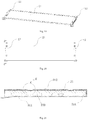
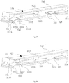
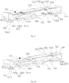
- the main body 121 further includes a partition plate 330 connected to the side plate 313, and the bottom plate 311, the top plate 312 and the partition plate 330 define one of the plurality of slots 3101, as shown in Fig. 25 .
- Another of the plurality of slots 3101 is defined between the partition plate 330 and the bottom plate 311, and the flat plate member 21 may be inserted into the slot 3101, as shown in Fig. 26 .
- a third one of the plurality of slots 3101 is defined between the partition plate 330 and the top plate 312, and the flat plate member 21 may also be inserted into the slot 3101, as shown in Fig. 27 .
- three slots 3101 with different specifications may be defined between the bottom plate 311 and the top plate 312, and adapted to insertion of the flat plate members 21 with different specifications respectively.
- the main body 121 further includes a partition plate 330 connected to the side plate 313 and the bottom plate 311, and the bottom plate 311, the top plate 312 and the partition plate 330 define one of the plurality of slots 3101, as shown in Fig. 25 .
- Another of the plurality of slots 3101 is defined between the partition plate 330 and the top plate 312, so as to insert a flat plate member 21 with a different specification.
- the partition plate 330 in the present embodiment is connected to the side plate 313 and the bottom plate 311, thus further improving a structural strength of the partition plate 330 to prevent the partition plate 330 from being easily fractured after pressure.
- the bottom plate 311 includes a first connected side edge 3111 and a first free side edge 3112, and the first free side edge 3112 is provided opposite to the first connected side edge 3111.
- the first connected side edge 3111 is connected with the bottom edge 3131.
- the partition plate 330 includes a second connected side edge 331 and a second free side edge 332, the second free side edge 332 is provided opposite to the second connected side edge 331, and the second connected side edge 331 is connected with a side surface of the side plate 313.
- a distance L1 between the second free side edge 332 and the side plate 313 is less than a distance L2 between the first free side edge 3112 and the side plate 313; that is, L1 is less than L2, thereby defining slots 101 with different lengths, which may be suitable for mounting not only the flat plate members 21 with different thicknesses, but also the flat plate members 21 with different lengths, such that the rotating member 12 in the present application may realize a mounting operation for more flat plate members 21 with different specifications under conditions of the same height.
- the rotating member 12 further includes a limit plate 314, and the limit plate 314 is connected with the bottom plate 311, the side plate 313, and the top plate 312.
- the limit plate 314 may limit the flat plate member 21 to prevent the flat plate member 21 from sliding out from the other side.
- the elastic members 320 are provided at the top plate 312.
- the top plate 312 has two opposite first lateral sides 3121, the connecting portion 321 is connected to one first lateral side 3121, the elastic portion 322 has a third end 3221 and a fourth end 3222 opposite to the third end 3221, the third end 3221 is connected with the connecting portion 321, and the fourth end 3222 is configured as a free end.
- the fourth end 3222 of the elastic portion 322 is in a suspended state, such that the elastic member 320 has a better elasticity.
- two elastic members 320 are provided and symmetrically arranged at the top plate 312, and since the top plate 312 is made of plastic, the two elastic members 320 are symmetrically arranged at the top plate 312, such that the top plate 312 may maintain overall uniform deformation in a state of expansion with heat and contraction with cold.
- the elastic member 320 and the top plate 312 may be integrally formed and connected, with a simple processing operation and a high connection reliability.
- the elastic members 320 are provided at the bottom plate 311.
- the bottom plate 311 has two opposite second lateral sides 3113, the connecting portion 321 is connected to one second lateral side 3113, the elastic portion 322 has a third end 3221 and a fourth end 3222 opposite to the third end 3221, the third end 3221 is connected with the connecting portion 321, and the fourth end 3222 is configured as a free end.
- the fourth end 3222 of the elastic portion 322 is in a suspended state, such that the elastic member 320 has a better elasticity.
- two elastic members 320 are provided and symmetrically arranged at the bottom plate 311, and since the bottom plate 311 is made of plastic, the two elastic members 320 are symmetrically arranged at the bottom plate 311, such that the bottom plate 311 may maintain overall uniform deformation in a state of expansion with heat and contraction with cold.
- the elastic member 320 and the bottom plate 311 may be integrally formed and connected, with a simple processing operation and a high connection reliability.
- the elastic members 320 are provided at the top plate 312 and the bottom plate 311 respectively.
- the top plate 312 has two opposite first lateral sides 3121
- the bottom plate 311 has two opposite second lateral sides 3113
- the elastic portion 322 has a third end 3221 and a fourth end 3222 opposite to the third end 3221.
- the connecting portion 321 located at the top plate 312 is connected to one first lateral side 3121
- the third end 3221 located at the top plate 312 is connected with the connecting portion 321 located at the top plate 312, and the fourth end 3222 located at the top plate 312 is configured as a free end.
- the fourth end 3222 of the elastic portion 322 at the top plate is in a suspended state, such that the elastic member 320 has a better elasticity.
- the connecting portion 321 located at the bottom plate 311 is connected to one second lateral side 3113, the third end 3221 located at the bottom plate 311 is connected with the connecting portion 321 located at the bottom plate 311, and the fourth end 3222 located at the bottom plate 311 is configured as a free end. That is, the fourth end 3222 of the elastic portion 322 at the bottom plate is in a suspended state, such that the elastic member 320 has a better elasticity.
- the elastic member 320 located at the bottom plate 311 may be integrally formed and connected with the bottom plate 311, and the elastic member 320 located at the top plate 312 may be integrally formed and connected with the top plate 11, such that the processing operation is simple and convenient, and the connection is firmer and more reliable.
- the elastic members 320 are provided at the top plate 312, and the top plate 312 has two opposite first lateral sides 3121.
- Each elastic member 320 at the top plate 312 includes two connecting portions 321, one of the connecting portions 321 is connected to one first lateral side 3121, the other one of the connecting portions 321 is connected to the other first lateral side 3121, the elastic portion 322 has a third end 3221 and a fourth end 3222 opposite to the third end 3221, the third end 3221 is connected with one of the connecting portions 321, and the fourth end 3222 is connected with the other one of the connecting portions 321.
- the third end 3221 and the fourth end 3222 of the elastic portion 322 are connected with the top plate 312 by the connecting portions 321, thereby enhancing a structural strength of the elastic member 320 to prevent the elastic member 320 from being easily damaged.
- the elastic members 320 are provided at the bottom plate 311, the bottom plate 311 has two opposite second lateral sides 3113, each elastic member 320 at the bottom plate 311 includes two connecting portions 321, one of the connecting portions 321 is connected to one second lateral side 3113, the other one of the connecting portions 321 is connected to the other second lateral side 3113, the elastic portion 322 has a third end 3221 and a fourth end 3222 opposite to the third end 3221, the third end 3221 is connected with one of the connecting portions 22, and the fourth end 3222 is connected with the other one of the connecting portions 22.
- the third end 3221 and the fourth end 3222 of the elastic portion 322 are connected with the bottom plate 311 by the connecting portions 321, thereby enhancing the structural strength of the elastic member 320 to prevent the elastic member 320 from being easily damaged.
- the elastic members 320 are provided at the bottom plate 311 and the top plate 312 respectively, the top plate 312 has two opposite first lateral sides 3121, the bottom plate 311 has two opposite second lateral sides 3113, and the elastic portion 322 has a third end 3221 and a fourth end 3222 opposite to the third end 3221.
- Each elastic member 320 located at the top plate 312 includes two connecting portions 321, one of the connecting portions 321 located at the top plate 312 is connected to one first lateral side 3121, the other one of the connecting portions 321 located at the top plate 312 is connected to the other first lateral side 3121, the third end 3221 located at the top plate 312 is connected with one of the connecting portions 321 located at the top plate 312, and the fourth end 3222 located at the top plate 312 is connected with the other one of the connecting portions 321 located at the top plate 312.
- the third end 3221 and the fourth end 3222 of the elastic portion 322 at the top plate 312 are connected with the top plate 312 by the connecting portions 321, thereby enhancing the structural strength of the elastic member 320 to prevent the elastic member 320 from being easily damaged.
- Each elastic member 320 located at the bottom plate 311 includes two connecting portions 321, one of the connecting portions 321 located at the bottom plate 311 is connected to one second lateral side 3113, the other one of the connecting portions 321 located at the bottom plate 311 is connected to the other second lateral side 3113, the third end 221 located at the bottom plate 311 is connected with one of the connecting portions 321 located at the bottom plate 311, and the fourth end 3222 located at the bottom plate 311 is connected with the other one of the connecting portions 321 located at the bottom plate 311.
- the third end 3221 and the fourth end 3222 of the elastic portion 322 are connected with the bottom plate 311 by the connecting portions 321, thereby enhancing the structural strength of the elastic member 320 to prevent the elastic member 320 from being easily damaged.
- a reinforcing rib 323 is provided on a side of the elastic portion 322 away from the slot 3101, thus enhancing the structural strength of the elastic member 320 to prevent the elastic member 320 from being easily damaged.
- the elastic member 320 is configured as an arc-shaped elastic sheet, such that transition is smoother and more natural, the elastic deformation is better, the mounting operation is smooth, and detachment is convenient.
- the rotating connection is realized by inserting the head 124 of the rotating shaft 123 through the mounting groove 112, then sliding the head 124 into the rotating shaft groove 111 and limiting the limiting member 122 in the limiting groove 113, the relative positions between the rotating member 12 and the fixed member 11 may be fixed by elastic fitting of the positioning member and the positioning hole 114, and at this point, the first mounting portion 115 of the fixed member 11 is engaged with the second mounting portion 126 of the rotating member 12; the connecting holes of the second mounting portion 126 and the first mounting portion 115 may be correspondingly connected by common mechanical means including, but not limited to, screws, so as to fixedly connect the rotating member 12 and the fixed member 11; the disassembly may be realized by releasing the fixed connection relationship between the second mounting portion 126 and the first mounting portion 115, elastically pushing the positioning protrusion 1251 of the positioning sheet 125 out of the positioning hole 114, pushing the limiting member 122 out of the
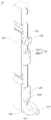
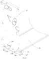
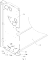
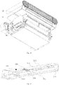
- FIG. 1 to 14 another embodiment of the present application provides an indoor unit of an air conditioner, including a filter assembly 21, a unit body 22, and a connecting mechanism connecting the filter assembly 21 to the unit body 22;
- the connecting mechanism is configured as a rotating connection structure, and the rotating connection structure includes a rotating member 12 rotatably mounted at the unit body 22 and a limiting member 122 limiting rotation of the rotating member 12 relative to the unit body 22 to be within a preset working angle range;
- the filter assembly 21 is mounted at the rotating member 12, the filter assembly 21 rotates with rotation of the rotating member 12 relative to the unit body 22, and the filter assembly 21 is exposed outside the unit body 22 after the rotating member 12 rotates.
- the filter assembly 21 is mounted at the rotating member 12, and connected with the unit body 22 by the rotating connection structure, and the filter assembly 21 may rotate along with the rotation of the rotating member 12 relative to the unit body 22; specifically, when in practical applications, the filter assembly 21 is required to be disassembled for later cleaning and maintenance, the filter assembly 21 may be rotated relative to the unit body 22 by the rotating member 12, so as to separately disassemble the filter assembly 21 for cleaning and maintenance, without damaging the connection structure between the filter assembly 21 and the unit body 22.
- a rotating shaft groove 111, a mounting groove 112 and a limiting groove 113 are formed in the unit body 22, and the rotating member 12 includes a main body 121, a rotating shaft 123 connected to the main body 121 and a head 124 connected to the rotating shaft 123; the head 124 passes through the mounting groove 112 and makes the rotating shaft 123 slide from the mounting groove 112 into the rotating shaft groove 111, the rotating shaft 123 is capable of rotating in the rotating shaft groove 111, and the head 124 is stopped outside the rotating shaft groove 111; the limiting member 122 is elastically deformed when the rotating shaft 123 slides from the mounting groove 112 to the rotating shaft groove 111, and recovers from the elastic deformation and is limited in the limiting groove 113 when the rotating shaft 123 slides into the rotating shaft groove 111, and a sliding range of the limiting member 122 in the limiting groove 113 includes the preset working angle range of the rotating member
- the filter assembly 21 may be rotatably connected with the unit body 22 by means of the rotating connection structure by inserting the head 124 of the rotating shaft 123 through the mounting groove 112, then sliding the head 124 into the rotating shaft groove 111 and limiting the limiting member 122 in the limiting groove 113, and subsequently, the filter assembly 21 may be disassembled from the unit body 22 by pushing the limiting member 122 out of the limiting groove 113, sliding the head 124 of the rotating shaft 123 back to the mounting groove 112 and pushing the head 124 out, such that the filter assembly 21 is convenient to disassemble and assemble, and may be disassembled and assembled repeatedly, and the connection structure between the filter assembly 21 and the unit body 22 is not prone to damage, thus facilitating subsequent disassembly, assembly, cleaning and maintenance of the filter assembly 21.
- FIG. 2 another embodiment of the present application provides an indoor unit of an air conditioner, and the rotating shaft groove 111, the mounting groove 112 and the limiting groove 113 are in communication with one another.
- the limiting groove 113 is provided close to the mounting groove 112, the limiting groove 113 and the mounting groove 112 are in communication with each other, and the overall radial size of the limiting groove 113 and the mounting groove 112 should be greater than the radial size of the head 124 of the rotating shaft 123, such that the head 124 of the rotating shaft 123 passes through the mounting groove 112; the other side of the limiting groove 113 away from the side in communication with the mounting groove 112 should be disposed in an arc shape, and the radians spanned by the limiting groove 113 should be not less than the preset working angle range of the rotating member 12.
- the limiting member 122 and the rotating shaft 123 have a small center distance, and in the mounting process, the limiting member 122 may be limited in the limiting groove 113 only by generating small elastic deformation.
- the filter assembly 21 may rotate within a slidable range of the limiting groove 113 along with the rotating connection structure.
- FIG. 3 another embodiment of the present application provides an indoor unit of an air conditioner, the rotating shaft groove 111 is in communication with the mounting groove 112, and the limiting groove 113 and the mounting groove 112 are separately disposed independently.
- the rotating shaft groove 111 is in communication with the mounting groove 112, so as to allow the head 124 of the rotating shaft 123 to pass through the mounting groove 112 and then slide into the rotating shaft groove 111, such that the head 124 of the rotating shaft 123 and the main body 121 of the rotating shaft 123 are located on two opposite sides of the fixed member 11 respectively;
- the limiting groove 113 and the mounting groove 112 are separately disposed independently, and the center distance between the limiting member 122 and the rotating shaft 123 should be within the range of the maximum distance between the limiting groove 113 and the rotating shaft groove 111, such that the limiting member 122 may be limited in the limiting groove 113 before the rotating shaft 123 slides to the end of the rotating shaft groove 111.
- the separate and independent arrangement of the mounting groove 112 and the limiting groove 113 facilitates a processing operation and easily guarantees size precision of the mounting groove 112 and the limiting groove 113.
- the filter assembly 21 may rotate within a slidable range of the limiting groove 113 along with the rotating connection structure.
- the limiting member 122 includes an elastic sheet 1221 and a limiting protrusion 1222
- the elastic sheet 1221 has a first end and a second end opposite to the first end
- the first end of the elastic sheet 1221 is connected to the main body 121 of the rotating member 12
- the second end of the elastic sheet 1221 is configured as a free end
- the limiting protrusion 1222 is provided at the second end and limited in the limiting groove 113.
- the limiting member 122 includes the elastic sheet 1221 and the limiting protrusion 1222, the elastic sheet 1221 has the first end and the second end opposite to the first end, the first end of the elastic sheet 1221 is connected to the main body 121 of the rotating member 12, the second end of the elastic sheet 1221 is configured as a free end, and the limiting protrusion 1222 is provided at the second end and limited in the limiting groove 113.
- the elastic sheet 1221 is disposed transversely, and has one fixed end and the other free end, the limiting protrusion 1222 is provided at the free end, a part below the elastic sheet 1221 is hollowed to retain a space for the elastic sheet 1221 to generate elastic deformation, and the limiting member 122 has an elastic effect due to the elastic sheet 1221 and may be elastically deformed.
- FIG. 4 to 6 another embodiment of the present application provides an indoor unit of an air conditioner, the unit body 22 is provided with a mounting position for mounting the rotating member 12, and the elastic sheet 1221 is elastically deformed in a direction away from the mounting position when the rotating shaft 123 slides from the mounting groove 112 to the rotating shaft groove 111.
- the first end of the elastic sheet 1221 is connected to the main body 121 of the rotating member 12, the second end of the elastic sheet 1221 is configured as a free end, and the limiting protrusion 1222 is provided at the second end, such that when the rotating shaft 123 slides from the mounting groove 112 towards the rotating shaft groove 111 and the limiting member 122 does not yet reach the limiting groove 113, the second end of the elastic sheet 1221 is elastically deformed in the direction away from the fixed member 11, thereby minimizing friction between the limiting member 122 and the fixed member 11, avoiding abrasion at corresponding positions of the limiting member 122 and the fixed member 11, and prolonging service lives thereof; when the rotating shaft 123 slides from the mounting groove 112 towards the rotating shaft groove 111 and the limiting member 122 reaches the limiting groove 113, under the elastic effect of the elastic sheet 1221, the limiting member 122 recovers from the elastic deformation and is limited in the limiting groove 113, so as to mount the rotating member 12 and the fixed member 11, thereby rotatably
- FIG. 7 to 9 another embodiment of the present application provides an indoor unit of an air conditioner, the elastic sheet 1221 is vertically provided at the main body 121 of the rotating member 12, and the elastic sheet 1221 is elastically deformed in a direction opposite to the sliding direction of the rotating shaft 123 when the rotating shaft 123 slides from the mounting groove 112 towards the rotating shaft groove 111.
- the elastic sheet 1221 is vertically provided at the main body 121 of the rotating member 12, one end of the elastic sheet 1221 is connected to the main body 121 of the rotating member 12, the other end of the elastic sheet 1221 is connected to the limiting protrusion 1222, and spaces are left on both sides of the elastic sheet 1221 that do not interfere with the elastic deformation of the elastic sheet 1221; specifically, when the rotating shaft 123 slides from the mounting groove 112 towards the rotating shaft groove 111 and the limiting member 122 does not yet reach the limiting groove 113, the second end of the elastic sheet 1221 is elastically deformed in the direction opposite to the sliding direction of the rotating shaft 123, thereby minimizing the friction between the limiting member 122 and the fixed member 11, avoiding the abrasion at the corresponding positions of the limiting member 122 and the fixed member 11, and prolonging the service lives thereof; when the rotating shaft 123 slides from the mounting groove 112 towards the rotating shaft groove 111 and the limiting member 122 reaches the limiting groove 113, under the elastic effect
- FIG. 2 to 9 another embodiment of the present application provides an indoor unit of an air conditioner
- the indoor unit of an air conditioner further includes a positioning sheet 125, a positioning protrusion 1251 is provided at the positioning sheet 125, a positioning hole 114 is formed in the unit body 22, and the positioning protrusion 1251 is elastically inserted into the positioning hole 114 when the rotating member 12 and the unit body 22 have fixed relative positions.
- the rotating member 12 is provided with the positioning sheet 125, the positioning hole 114 with a size matched with a size of the positioning protrusion 1251 is formed in the corresponding position of the fixed member 11, and when the rotating connection structure is not required to rotate and the relative positions of the rotating member 12 and the fixed member 11 are necessary to be kept fixed, the positioning protrusion 1251 is elastically inserted into the positioning hole 114, such that relative positions of the filter assembly 21 and the unit body 22 may be kept fixed, thereby mounting the filter assembly 21 in the indoor unit of an air conditioner to realize a filtering function; when the rotating connection structure is required to be rotated or disassembled, the positioning protrusion 1251 is elastically pushed out of the positioning hole 114 to release the fixed relationship, such that the filter assembly 21 may rotate along with the rotating connection structure, so as to separately disassemble the filter assembly 21 for cleaning and maintenance, without damaging the connection structure between the filter assembly 21 and the unit body 22.
- the positioning sheet 125 has a first end and a second end opposite to the first end, the first end of the positioning sheet 125 is connected to the rotating member 12, the second end of the positioning sheet 125 is configured as a free end, and the positioning protrusion 1251 is provided at the second end.
- the positioning sheet 1221 is disposed transversely, and has one fixed end and the other free end, the positioning protrusion 1251 is provided at the free end, a part below the positioning sheet 1221 is hollowed to retain a space for the positioning sheet 1221 to generate elastic deformation, and the positioning sheet 125 has an elastic effect and may be elastically deformed.
- the positioning protrusion 1251 of the positioning sheet 125 is provided away from the limiting protrusion 1222 of the limiting member 122, so as to reduce a space of the main body 121 occupied by the positioning sheet 125 and the limiting member 122 to a certain extent.
- the positioning sheet 125 may be fitted with the positioning hole 114 to ensure that the filter assembly 21 and the unit body 22 have fixed relative positions.
- FIG. 4 to 9 another embodiment of the present application provides an indoor unit of an air conditioner, the unit body 22 is provided with a mounting position for mounting the rotating member 12, and the positioning sheet 125 is elastically deformed in a direction away from the mounting position when the rotating shaft 123 slides from the mounting groove 112 to the rotating shaft groove 111.
- the second end of the positioning sheet 125 is elastically deformed in the direction away from the fixed member 11, thereby minimizing friction between the positioning sheet 125 and the fixed member 11, avoiding abrasion at corresponding positions of the positioning sheet 125 and the fixed member 11, and prolonging service lives thereof;
- the positioning sheet 125 may recover from the elastic deformation and be limited in the positioning hole 114, so as to fix the relative positions of the rotating member 12 and the fixed member 11, thereby fixing the relative positions of the filter assembly 21 and the unit body 22.
- FIG. 1 another embodiment of the present application provides an indoor unit of an air conditioner, and the filter assembly 21 is inserted to the rotating member 12.
- the fixed member 11 is provided with the first mounting portion 115
- the first mounting portion 115 is provided on the side of the fixed member 11 opposite to a rotating end of the rotating member 12, and is recessed inwards, so as to leave a space engaged with the second mounting portion 126 of the rotating member 12
- the rotating member 12 is provided with the second mounting portion 126 perpendicular to the main body 121 of the rotating member 12, and when the rotating member 12 and the fixed member 11 have fixed relative positions, the first mounting portion 115 is engaged with the second mounting portion 126
- connecting holes are defined in corresponding positions of the first mounting portion 115 and the second mounting portion 126, and may be correspondingly connected by common mechanical means including, but not limited to, screws, so as to fixedly connect the rotating member 12 and the fixed member 11, thereby fixing the relative positions of the filter assembly 21 and the unit body 22; when the rotating
- FIG. 12 another embodiment of the present application provides an indoor unit of an air conditioner
- the rotating member 12 is provided with a wrench 127 configured to rotate the rotating member 12, and the wrench 127 is exposed out of the unit body 22.
- the rotating member 12 is provided with the wrench 127 configured to rotate the rotating member 12, and the wrench 127 is disposed perpendicular to the second mounting portion 126 of the rotating member 12.
- the wrench 127 When the rotating member 12 and the fixed member 11 have fixed relative positions and the first mounting portion 115 is engaged with the second mounting portion 126, the wrench 127 is exposed outside the unit body 22, and during release of the fixation of the relative positions between the rotating member 12 and the fixed member 11, an operator may rotate the rotating member 12 by holding the wrench 127 with hands to drive the filter assembly 21 to rotate with the rotating member 12, so as to separately disassemble the filter assembly 21 for cleaning and maintenance, without damaging the connection structure between the filter assembly 21 and the unit body 22.
- the filter assembly 21 is rotatably connected with the unit body 22 by inserting the head 124 of the rotating shaft 123 provided with the filter assembly 21 through the mounting groove 112, then sliding the head 124 into the rotating shaft groove 111 and limiting the limiting member 122 in the limiting groove 113, the relative positions between the filter assembly 21 and the unit body 22 may be fixed by elastic fitting of the positioning member and the positioning hole 114, and at this point, the first mounting portion 115 of the fixed member 11 is engaged with the second mounting portion 126 of the rotating member 12; the connecting holes of the second mounting portion 126 and the first mounting portion 115 may be correspondingly connected by common mechanical means including, but not limited to, screws, so as to fixedly connect the filter assembly 21 and the unit body 22; the filter assembly 21 may be disassembled from the unit body 22 by releasing the fixed connection relationship between the second mounting portion 126 and the first mounting portion 115, elastically pushing the positioning protrusion 12
- the rotating connection is realized by inserting the head 124 of the rotating shaft 123 through the mounting groove 112, then sliding the head 124 into the rotating shaft groove 111 and limiting the limiting member 122 in the limiting groove 113, and the disassembly may be subsequently realized by pushing the limiting member 122 out of the limiting groove 113, sliding the head 124 of the rotating shaft 123 back to the mounting groove 112 and pushing the head 124 out, such that the rotating connection structure is convenient to disassemble and assemble, may be disassembled and assembled repeatedly, and is not prone to damage, thus facilitating subsequent disassembly, assembly and maintenance.
- the filter assembly 21 is mounted in the rotating member 12 in the above-mentioned rotating connection structure to achieve the rotating connection between the filter assembly 21 and the unit body 22, such that the filter assembly 21 may rotate along with the rotating connection structure, and the filter assembly 21 may be conveniently detached independently to be cleaned and maintained, without damaging the connection structure between the filter assembly 21 and the unit body 22.
- the present application provides an air conditioner, including the indoor unit of an air conditioner as mentioned above.
- the filter assembly 21 is mounted in the rotating member 12 in the above-mentioned rotating connection structure to achieve the rotating connection between the filter assembly 21 and the unit body 22, such that the filter assembly 21 may rotate along with the rotating connection structure, and the filter assembly 21 may be conveniently detached independently to be cleaned and maintained, without damaging the connection structure between the filter assembly 21 and the unit body 22.
Landscapes
- Engineering & Computer Science (AREA)
- Chemical & Material Sciences (AREA)
- Combustion & Propulsion (AREA)
- Mechanical Engineering (AREA)
- General Engineering & Computer Science (AREA)
- Connection Of Plates (AREA)
- Pivots And Pivotal Connections (AREA)
Abstract
Description
- The present application is based on and claims priority to
Chinese Patent Application Serial Nos. 201811641984.6 201822277837.7, filed on December 29, 2018 - The present application relates to the field of air conditioner technologies, and particularly to an air conditioner, an indoor unit of the air conditioner and a rotating connection structure thereof.
- An indoor unit of an air conditioner is one of common household appliances, and a quality of life of people is improved by cooling and heating functions of the indoor unit of an air conditioner. Usually, a filter screen is required to be additionally mounted to prevent dust from entering the indoor unit of an air conditioner along with air flow, and after the filter screen is used for a long time, a thick layer of dust may adhere to the filter screen affecting air quality, and therefore, the filter screen is necessary to be frequently detached and cleaned. Currently, the filter screen is connected with a housing of the indoor unit of an air conditioner usually by forcibly clamping an elastic end into a round hole. To disassemble the filter screen from the housing of the indoor unit of an air conditioner, a technical person with professional skills must use professional disassembly tools to damage a connection structure of the filter screen and the housing.
- The present application is intended to provide a rotating connection structure and an indoor unit of an air conditioner, which aim at solving the technical problem that a connection structure between a filter screen and a housing of an indoor unit of an air conditioner is damaged during disassembly in the prior art.
- In order to solve the above-mentioned technical problem, an embodiment of the present application provides a rotating connection structure, the rotating connection structure including a fixed member and a rotating member configured to rotate relative to the fixed member within a preset working angle range, a rotating shaft groove, a mounting groove and a limiting groove being defined on the fixed member, and the rotating member including a main body, a limiting member, a rotating shaft connected on the main body and a head connected to the rotating shaft; the head passing through the mounting groove such that the rotating shaft slides from the mounting groove into the rotating shaft groove, the rotating shaft being capable of rotating in the rotating shaft groove, the head being stopped outside the rotating shaft groove, and the head and the main body being located at two opposite sides of the fixed member; the limiting member being elastically deformed when the rotating shaft slides from the mounting groove to the rotating shaft groove, and recovering from the elastic deformation and being limited in the limiting groove when the rotating shaft slides into the rotating shaft groove, and a sliding range of the limiting member in the limiting groove including the preset working angle range of the rotating member.
- Optionally, the rotating shaft groove, the mounting groove and the limiting groove are in communication with one another.
- Optionally, the rotating shaft groove and the mounting groove are in communication with each other, and the limiting groove and the mounting groove are separately arranged independently.
- Further, the limiting member includes an elastic sheet and a limiting protrusion, the elastic sheet has a first end and a second end opposite to the first end, the first end of the elastic sheet is connected to the main body of the rotating member, the second end of the elastic sheet is configured as a free end, and the limiting protrusion is provided on the second end and limited in the limiting groove.
- Further, the elastic sheet is elastically deformed in a direction away from the fixed member when the rotating shaft slides from the mounting groove towards the rotating shaft groove.
- Optionally, the elastic sheet is vertically provided on the main body of the rotating member, and when the rotating shaft slides from the mounting groove towards the rotating shaft groove, the elastic sheet is elastically deformed in a direction opposite to the sliding direction of the rotating shaft.
- Further, the rotating member further includes a positioning sheet connected to the main body, a positioning protrusion is provided on the positioning sheet, a positioning hole is defined on the fixed member, and the positioning protrusion is elastically inserted into the positioning hole when the rotating member and the fixed member have fixed relative positions.
- Further, the positioning sheet has a first end and a second end opposite to the first end, the first end of the positioning sheet is connected to the main body of the rotating member, the second end of the positioning sheet is configured as a free end, and the positioning protrusion is provided on the second end.
- Further, the positioning sheet is elastically deformed in a direction away from the fixed member when the rotating shaft slides from the mounting groove towards the rotating shaft groove.
- Further, a first mounting portion is provided on the fixed member, a second mounting portion is provided on the rotating member, and when the rotating member and the fixed member have fixed relative positions, the second mounting portion is connected on the first mounting portion.
- Optionally, the main body has two opposite sides, a plurality of slots adapted to different flat plate members are defined in one side of the main body, the other side of the main body is rotatably connected on the fixed member, and an elastic member is provided on one side of each slot and elastically abuts against a flat plate member.
- Optionally, the elastic member includes a connecting portion connected to a side portion of the slot and an elastic portion protruding and extending from the connecting portion towards an interior of the slot, and the elastic portion is separated from the side portion of the slot by the connecting portion.
- Optionally, the main body includes a bottom plate, a top plate, and a side plate, the bottom plate is provided opposite to the top plate, the side plate has a bottom edge and a top edge opposite to the bottom edge, the bottom edge is connected with the bottom plate, the top edge is connected with the top plate, and the bottom plate and the top plate are enclosed to form one of the plurality of slots.
- Optionally, the main body further includes a partition plate connected on the side plate, the bottom plate, the top plate and the partition plate form one of the plurality of slots, the partition plate and the bottom plate form another of the plurality of slots, and the partition plate and the top plate form a third one of the plurality of slots.
- Optionally, the main body further includes a partition plate connected to the side plate and the bottom plate, the bottom plate, the top plate and the partition plate define one of the plurality of slots, and another of the plurality of slots is defined between the partition plate and the top plate.
- Optionally, the bottom plate includes a first connected side edge and a first free side edge provided opposite to the first connected side edge, the first connected side edge is connected with the bottom edge, the partition plate includes a second connected side edge and a second free side edge provided opposite to the second connected side edge, the second connected side edge is connected with a side surface of the side plate, and a distance between the second free side edge and the side plate is less than a distance between the first free side edge and the side plate.
- Optionally, the elastic members are provided on the top plate, the top plate has two opposite first lateral sides, the connecting portion is connected to one of the first lateral sides, the elastic portion has a third end and a fourth end opposite to the third end, the third end is connected with the connecting portion, and the fourth end is configured as a free end.
- Optionally, the elastic members are provided on the bottom plate, the bottom plate has two opposite second lateral sides, the connecting portion is connected to one of the second lateral sides, the elastic portion has a third end and a fourth end opposite to the third end, the third end is connected with the connecting portion, and the fourth end is configured as a free end.
- Optionally, the elastic members are provided at the top plate and the bottom plate respectively, the top plate has two opposite first lateral sides, the bottom plate has two opposite second lateral sides, and the elastic portion has a third end and a fourth end opposite to the third end; the connecting portion located on the top plate is connected to one of the first lateral sides, the third end located on the top plate is connected with the connecting portion located on the top plate, and the fourth end located on the top plate is configured as a free end; and the connecting portion located on the bottom plate is connected on one of the second lateral sides, the third end located on the bottom plate is connected with the connecting portion located on the bottom plate, and the fourth end located on the bottom plate is configured as a free end.
- Optionally, the elastic members are provided on the top plate, the top plate has two opposite first lateral sides, each elastic member on the top plate includes the two connecting portions, one of the connecting portions is connected on one of the first lateral sides, the other one of the connecting portions is connected on the other one of the first lateral sides, the elastic portion has a third end and a fourth end opposite to the third end, the third end is connected with one of the connecting portions, and the fourth end is connected with the other one of the connecting portions.
- Optionally, the elastic members are provided on the bottom plate, the bottom plate has two opposite second lateral sides, each elastic member on the bottom plate includes the two connecting portions, one of the connecting portions is connected on one of the second lateral sides, the other one of the connecting portions is connected to the other one of the second lateral sides, the elastic portion has a third end and a fourth end opposite to the third end, the third end is connected with one of the connecting portions, and the fourth end is connected with the other one of the connecting portions.
- Optionally, the elastic members are provided at the top plate and the bottom plate respectively, the top plate has two opposite first lateral sides, the bottom plate has two opposite second lateral sides, and the elastic portion has a third end and a fourth end opposite to the third end; each elastic member located on the top plate includes the two connecting portions, one of the connecting portions located on the top plate is connected on one of the first lateral sides, the other one of the connecting portions located on the top plate is connected on the other one of the first lateral side, the third end located on the top plate is connected with one of the connecting portions located on the top plate, and the fourth end located on the top plate is connected with the other one of the connecting portions located on the top plate; and each elastic member located on the bottom plate includes the two connecting portions, one of the connecting portions located on the bottom plate is connected on one of the second lateral sides, the other one of the connecting portions located on the bottom plate is connected to the other one of the second lateral sides, the third end located on the bottom plate is connected with one of the connecting portions located on the bottom plate, and the fourth end located on the bottom plate is connected with the other one of the connecting portions located on the bottom plate.
- Optionally, a reinforcing rib configured to enhance a structural strength of the elastic member is provided on a side of the elastic portion away from the slot.
- One or more technical solutions of the rotating connection structure according to the embodiment of the present application have at least one of the following technical effects.
- In the above-mentioned rotating connection structure, a rotating connection is realized by inserting the head of the rotating shaft through the mounting groove, then sliding the head into the rotating shaft groove and limiting the limiting member in the limiting groove, and disassembly may be subsequently realized by pushing the limiting member out of the limiting groove, sliding the head of the rotating shaft back to the mounting groove and pushing the head out, such that the above-mentioned rotating connection structure is convenient to disassemble and assemble, may be disassembled and assembled repeatedly, and is not prone to damage, thus facilitating subsequent disassembly, assembly and maintenance.
- An embodiment of the present application provides an indoor unit of an air conditioner, including a filter assembly, a unit body, and a connecting mechanism connecting the filter assembly to the unit body; the connecting mechanism being configured as a rotating connection structure, and the rotating connection structure including a rotating member rotatably mounted at the unit body and a limiting member limiting rotation of the rotating member relative to the unit body to be within a preset working angle range; the filter assembly being mounted on the rotating member, the filter assembly rotating with rotation of the rotating member relative to the unit body, and the filter assembly being exposed outside the unit body after the rotating member rotates.
- Further, a rotating shaft groove, a mounting groove and a limiting groove are defined on the unit body, and the rotating member includes a main body, a rotating shaft connected to the main body and a head connected to the rotating shaft; the head passes through the mounting groove such that the rotating shaft slides from the mounting groove into the rotating shaft groove, the rotating shaft is capable of rotating in the rotating shaft groove, and the head is stopped outside the rotating shaft groove; the limiting member is elastically deformed when the rotating shaft slides from the mounting groove towards the rotating shaft groove, and recovers from the elastic deformation and is limited in the limiting groove when the rotating shaft slides into the rotating shaft groove, and a sliding range of the limiting member in the limiting groove includes the preset working angle range of the rotating member.
- Optionally, the rotating shaft groove, the mounting groove and the limiting groove are in communication with one another.
- Optionally, the rotating shaft groove and the mounting groove are in communication with each other, and the limiting groove and the mounting groove are separately arranged independently.
- Further, the limiting member includes an elastic sheet and a limiting protrusion, the elastic sheet has a first end and a second end opposite to the first end, the first end of the elastic sheet is connected to the main body of the rotating member, the second end of the elastic sheet is configured as a free end, and the limiting protrusion is provided on the second end and is limited in the limiting groove.
- Further, the unit body is provided with a mounting position for mounting the rotating member, and the elastic sheet is elastically deformed in a direction away from the mounting position when the rotating shaft slides from the mounting groove towards the rotating shaft groove.
- Optionally, the elastic sheet is vertically provided on the main body of the rotating member, and when the rotating shaft slides from the mounting groove towards the rotating shaft groove, the elastic sheet is elastically deformed in a direction opposite to the sliding direction of the rotating shaft.
- Further, the indoor unit of an air conditioner further includes a positioning sheet, a positioning protrusion is provided at the positioning sheet, a positioning hole is defined in the unit body, and the positioning protrusion is elastically inserted into the positioning hole when the rotating member and the unit body have fixed relative positions.
- Further, the positioning sheet has a first end and a second end opposite to the first end, the first end of the positioning sheet is connected on the rotating member, the second end of the positioning sheet is configured as a free end, and the positioning protrusion is provided on the second end.
- Further, the unit body is provided with a mounting position for mounting the rotating member, and the positioning sheet is elastically deformed in a direction away from the mounting position when the rotating shaft slides from the mounting groove to the rotating shaft groove.
- Further, the filter assembly is inserted on the rotating member.
- Further, the rotating member is provided with a wrench configured to rotate the rotating member, and the wrench is exposed outside the unit body.
- One or more technical solutions of the indoor unit of an air conditioner according to the embodiment of the present application have at least one of the following technical effects.
- In the above-mentioned indoor unit of an air conditioner, the filter assembly is mounted in the rotating member in the above-mentioned rotating connection structure to achieve a rotating connection between the filter assembly and the unit body, such that the filter assembly may rotate along with the rotating connection structure, and the filter assembly may be conveniently and subsequently detached independently at any time to be cleaned and maintained, without damaging a connection structure between the filter assembly and the unit body.
- An embodiment of the present application provides an air conditioner, including the indoor unit of an air conditioner as mentioned above.
- In the above-mentioned air conditioner, the filter assembly is mounted in the rotating member in the above-mentioned rotating connection structure to achieve the rotating connection between the filter assembly and the unit body, such that the filter assembly may rotate along with the rotating connection structure, and the filter assembly may be conveniently and subsequently detached independently at any time to be cleaned and maintained, without damaging the connection structure between the filter assembly and the unit body.
-
-
Fig. 1 is a schematic perspective structural diagram of a rotating connection structure according to an embodiment of the present application; -
Fig. 2 is a schematic perspective structural diagram of a fixed member ofFig. 1 ; -
Fig. 3 is a schematic perspective structural diagram of a fixed member according to another embodiment of the present application; -
Fig. 4 is a schematic perspective structural diagram of a rotating member ofFig. 1 ; -
Fig. 5 is a front view of the rotating member ofFig. 4 ; -
Fig. 6 is a schematic sectional structural diagram of the rotating member taken along A-A inFig. 5 ; -
Fig. 7 is a schematic perspective structural diagram of a rotating member according to another embodiment of the present application; -
Fig. 8 is a front view of the rotating member ofFig. 7 ; -
Fig. 9 is a schematic sectional structural diagram of the rotating member taken along B-B inFig. 8 ; -
Fig. 10 is a first schematic mounting diagram of the rotating connection structure ofFig. 1 ; -
Fig. 11 is a second schematic mounting diagram of the rotating connection structure ofFig. 10 ; -
Fig. 12 is a schematic rotational diagram of the rotating connection structure ofFig. 11 ; -
Fig. 13 is a schematic perspective structural diagram of an indoor unit of an air conditioner according to an embodiment of the present application; -
Fig. 14 is a schematic exploded structural diagram of the indoor unit of an air conditioner ofFig. 13 ; -
Fig. 15 is a schematic perspective structural diagram of a rotating member according to another embodiment of the present application; -
Fig. 16 is a top view of the rotating member according to the embodiment of the present application; -
Fig. 17 is a sectional structural view taken along line C-C inFig. 16 ; -
Fig. 18 is a schematic side structural diagram of the rotating member according to the embodiment of the present application; -
Fig. 19 is a schematic diagram after assembly of the rotating member and a flat plate member according to the embodiment of the present application; -
Fig. 20 is a top view after assembly of the rotating member and the flat plate member according to the embodiment of the present application; -
Fig. 21 is a sectional structural view taken along line D-D inFig. 20 ; -
Fig. 22 is a schematic partial enlarged diagram at E ofFig. 21 ; -
Fig. 23 is a schematic perspective structural diagram of a rotating member according to another embodiment of the present application; -
Fig. 24 is a schematic perspective structural diagram of the rotating member ofFig. 23 from another perspective; -
Fig. 25 is a schematic diagram of one use state of the rotating members ofFig. 23 ; -
Fig. 26 is a schematic diagram of another use state of the rotating members ofFig. 23 ; -
Fig. 27 is a schematic diagram of a third use state of the rotating members ofFig. 23 ; -
Fig. 28 is a schematic perspective structural diagram of a rotating member according to another embodiment of the present application; -
Fig. 29 is a schematic perspective structural diagram of a rotating member according to another embodiment of the present application; -
Fig. 30 is a schematic perspective structural diagram of a rotating member according to another embodiment of the present application; -
Fig. 31 is a schematic perspective structural diagram of a rotating member according to another embodiment of the present application; and -
Fig. 32 is a schematic perspective structural diagram of a rotating member according to another embodiment of the present application. - In order to make objects, technical solutions and advantages of the present application more apparent, the present application will be described in further detail with reference to the following drawings and embodiments. It should be understood that the specific embodiments described herein are merely for explaining the present application and are not intended to limit the present application.
- In the description of the embodiments of the present application, it is to be understood that terms such as "length", "width", "upper", "lower", "front", "rear", "left", "right", "vertical", "horizontal", "top", "bottom", "inner" and "outer" should be construed to refer to the orientation as then described or as shown in the drawings under discussion. These relative terms are for convenience of description and do not require that the present application be constructed or operated in a particular orientation, thus cannot be construed to limit the embodiments of the present application.
- In addition, the terms such as "first" and "second" are used herein for purposes of description and are not intended to indicate or imply relative importance or significance or to imply the number of indicated technical features. Thus, the feature defined with "first" and "second" may include one or more of this feature explicitly or implicitly. In the description of the present application, "a plurality of' means two or more unless otherwise specified.
- In the embodiments of the present application, unless specified or limited otherwise, the terms "mounted", "connected", "coupled", and "fixed" and the like are used broadly, and may be, for example, fixed connections, detachable connections, or integral connections; may also be mechanical or electrical connections; may also be direct connections or indirect connections via intervening structures; may also be communication or an interaction relationship of two elements. The above terms can be understood by those skilled in the art according to specific situations.
- Specific implementations of the present application are described in more detail below with reference to specific embodiments.
- An embodiment of the present application provides a rotating connection structure, and the rotating connection structure is configured to realize a rotating connection between two components, and may be repeatedly disassembled and assembled without damage.
- Referring to
Figs. 1 to 12 , in the present embodiment, the rotating connection structure includes a fixedmember 11 and a rotatingmember 12 rotating relative to the fixedmember 11 within a predetermined working angle range. - The fixed
member 11 is provided with arotating shaft groove 111, a mountinggroove 112 and a limitinggroove 113. It should be noted here that therotating shaft groove 111 and the mountinggroove 112 are in communication with each other, and the mountinggroove 112 should have a greater radial size than therotating shaft groove 111; the limitinggroove 113 is designed to have an arc shape, and radians spanned by the limitinggroove 113 should be not less than the preset working angle range of the rotatingmember 12. Therotating shaft groove 111 and the mountinggroove 112 provided in the fixedmember 11 are configured to realize a connection with the rotatingmember 12, and the limitinggroove 113 provided in the fixedmember 11 is configured to limit slide and rotation of the rotatingmember 12. - The rotating
member 12 includes amain body 121, a limitingmember 122, arotating shaft 123 connected to themain body 121, and ahead 124 connected to therotating shaft 123. It should be noted here that a rotating axis 123 of the rotating member 12 is located at a central axis of the rotating shaft 123 connected to the main body 121 of the rotating member 12; a center of the head 124 connected to the rotating shaft 123 should coincide with a center of the rotating shaft 123, such that the head 124 and the rotating shaft 123 are uniformly stressed after the rotating connection is realized; a radial size of the head 124 should be less than a radial size of the mounting groove 112 to enable the head 124 to pass through the mounting groove 112, and should be greater than a radial size of the rotating shaft groove 111 to enable the head 124 to be blocked outside the rotating shaft groove 111; a radial size of the rotating shaft 123 should be less than the radial size of the rotating shaft groove 111, such that the rotating shaft 123 may slide in the rotating shaft groove 111; a radial size of the limiting member 122 should be less than the radial size of the limiting groove 113, such that the limiting member 122 may slide in the limiting groove 113; a center distance between the limiting member 122 and the rotating shaft 123 should be within a range of the maximum distance between the limiting groove 113 and the rotating shaft groove 111, such that the limiting member 122 may be limited in the limiting groove 113 before the rotating shaft 123 slides to an end of the rotating shaft groove 111. - The
head 124 passes through the mountinggroove 112 and makes therotating shaft 123 slide from the mountinggroove 112 into therotating shaft groove 111, therotating shaft 123 may rotate in therotating shaft groove 111, thehead 124 is stopped outside therotating shaft groove 111, and thehead 124 and themain body 121 are located on two opposite sides of the fixedmember 11; the limitingmember 122 is elastically deformed when therotating shaft 123 slides from the mountinggroove 112 towards the rotatingshaft groove 111, and recovers from the elastic deformation and is limited in the limitinggroove 113 when therotating shaft 123 slides into therotating shaft groove 111, and a sliding range of the limitingmember 122 in the limitinggroove 113 includes the preset working angle range of the rotatingmember 12. - It should be noted here that, when the rotating
member 12 and the fixedmember 11 are mounted, referring toFig. 10 first, thehead 124 of therotating shaft 123 is inserted through the mountinggroove 112, and then, therotating shaft 123 is slid from the mountinggroove 112 into therotating shaft groove 111, such that thehead 124 of therotating shaft 123 and themain body 121 are located on two opposite sides of the fixedmember 11 respectively, and when therotating shaft 123 is slid from the mountinggroove 112 towards the rotatingshaft groove 111 and the limitingmember 122 does not yet reach the limitinggroove 113, the limitingmember 122 is elastically deformed in a direction away from the fixedmember 11; then, referring toFig. 11 , when therotating shaft 123 is slid from the mountinggroove 112 towards the rotatingshaft groove 111 and the limitingmember 122 reaches the limitinggroove 113, the limitingmember 122 recovers from the elastic deformation and is limited in the limitinggroove 113, and at this point, the rotatingmember 12 and the fixedmember 11 may be mounted; specifically, referring toFig. 12 , the rotatingmember 12 may rotate around therotating shaft 123 within a range limited by the limitinggroove 113. It should be further noted here that, when the rotating connection structure is required to be disassembled, the limitingmember 122 may be pushed out of the limitinggroove 113 by elasticity of the limitingmember 122 to release a limiting relationship, and then, thehead 124 is withdrawn from the mountinggroove 112 after therotating shaft 123 of the rotatingmember 12 is slid back from therotating shaft groove 111 to the mountinggroove 112, so as to disassemble the rotating connection structure without damaging the rotating connection structure. - In the rotating connection structure according to the embodiment of the present application, the rotating connection is realized by inserting the
head 124 of therotating shaft 123 through the mountinggroove 112, then sliding thehead 124 into therotating shaft groove 111 and limiting the limitingmember 122 in the limitinggroove 113, and the disassembly may be subsequently realized by pushing the limitingmember 122 out of the limitinggroove 113, sliding thehead 124 of therotating shaft 123 back to the mountinggroove 112 and pushing thehead 124 out, such that the rotating connection structure is convenient to disassemble and assemble, may be disassembled and assembled repeatedly, and is not prone to damage, thus facilitating subsequent disassembly, assembly and maintenance. - Referring to
Fig. 2 , in another embodiment of the present application, therotating shaft groove 111, the mountinggroove 112 and the limitinggroove 113 are in communication with one another. Specifically, on the basis that the mountinggroove 112 and therotating shaft groove 111 are in communication with each other, the limitinggroove 113 is provided close to the mountinggroove 112, the limitinggroove 113 and the mountinggroove 112 are in communication with each other, and an overall radial size of the limitinggroove 113 and the mountinggroove 112 should be greater than the radial size of thehead 124 of therotating shaft 123, such that thehead 124 of therotating shaft 123 passes through the mountinggroove 112; the other side of the limitinggroove 113 away from the side in communication with the mountinggroove 112 should be disposed in an arc shape, and the radians spanned by the limitinggroove 113 should be not less than the preset working angle range of the rotatingmember 12. Based on this structure, the limitingmember 122 and therotating shaft 123 have a small center distance, and in the mounting process, the limitingmember 122 may be limited in the limitinggroove 113 only by generating small elastic deformation. - Referring to
Fig. 3 , in another embodiment of the present application, therotating shaft groove 111 is in communication with the mountinggroove 112, and the limitinggroove 113 and the mountinggroove 112 are separately disposed independently. Specifically, therotating shaft groove 111 is in communication with the mountinggroove 112, so as to allow thehead 124 of therotating shaft 123 to pass through the mountinggroove 112 and then slide into therotating shaft groove 111, such that thehead 124 of therotating shaft 123 and themain body 121 of therotating shaft 123 are located on two opposite sides of the fixedmember 11 respectively; the limitinggroove 113 and the mountinggroove 112 are separately disposed independently, and the center distance between the limitingmember 122 and therotating shaft 123 should be within the range of the maximum distance between the limitinggroove 113 and therotating shaft groove 111, such that the limitingmember 122 may be limited in the limitinggroove 113 before therotating shaft 123 slides to the end of therotating shaft groove 111. Based on this structure, the separate and independent arrangement of the mountinggroove 112 and the limitinggroove 113 facilitates a processing operation and easily guarantees size precision of the mountinggroove 112 and the limitinggroove 113. - Referring to
Figs. 4 to 6 , in another embodiment of the present application, the limitingmember 122 includes anelastic sheet 1221 and a limitingprotrusion 1222, theelastic sheet 1221 has a first end and a second end opposite to the first end, the first end of theelastic sheet 1221 is connected to themain body 121 of the rotatingmember 12, the second end of theelastic sheet 1221 is configured as a free end, and the limitingprotrusion 1222 is provided at the second end and limited in the limitinggroove 113. It should be noted here that theelastic sheet 1221 is disposed transversely, and has one fixed end and the other free end, the limitingprotrusion 1222 is provided at the free end, a part below theelastic sheet 1221 is hollowed to retain a space for theelastic sheet 1221 to generate elastic deformation, and the limitingmember 122 has an elastic effect due to theelastic sheet 1221 and may be elastically deformed. - Referring to
Figs. 4 to 6 , in another embodiment of the present application, theelastic sheet 1221 is elastically deformed in a direction away from the fixedmember 11 when therotating shaft 123 slides from the mountinggroove 112 towards the rotatingshaft groove 111. The first end of theelastic sheet 1221 is connected to themain body 121 of the rotatingmember 12, the second end of theelastic sheet 1221 is configured as a free end, and the limitingprotrusion 1222 is provided at the second end, such that when therotating shaft 123 slides from the mountinggroove 112 towards the rotatingshaft groove 111 and the limitingmember 122 does not yet reach the limitinggroove 113, the second end of theelastic sheet 1221 is elastically deformed in the direction away from the fixedmember 11, thereby minimizing friction between the limitingmember 122 and the fixedmember 11, avoiding abrasion at corresponding positions of the limitingmember 122 and the fixedmember 11, and prolonging service lives thereof; when therotating shaft 123 slides from the mountinggroove 112 towards the rotatingshaft groove 111 and the limitingmember 122 reaches the limitinggroove 113, under the elastic effect of theelastic sheet 1221, the limitingmember 122 recovers from the elastic deformation and is limited in the limitinggroove 113, so as to realize the mounting between the rotatingmember 12 and the fixedmember 11. - Referring to
Figs. 7 to 9 , in another embodiment of the present application, theelastic sheet 1221 is vertically provided at themain body 121 of the rotatingmember 12, and theelastic sheet 1221 is elastically deformed in a direction opposite to the sliding direction of therotating shaft 123 when therotating shaft 123 slides from the mountinggroove 112 towards the rotatingshaft groove 111. It should be noted that the elastic sheet 1221 is vertically provided at the main body 121 of the rotating member 12, one end of the elastic sheet 1221 is connected to the main body 121 of the rotating member 12, the other end of the elastic sheet 1221 is connected to the limiting protrusion 1222, and spaces are left on both sides of the elastic sheet 1221 that do not interfere with the elastic deformation of the elastic sheet 1221; specifically, when the rotating shaft 123 slides from the mounting groove 112 towards the rotating shaft groove 111 and the limiting member 122 does not yet reach the limiting groove 113, the second end of the elastic sheet 1221 is elastically deformed in the direction opposite to the sliding direction of the rotating shaft 123, thereby minimizing the friction between the limiting member 122 and the fixed member 11, avoiding the abrasion at the corresponding positions of the limiting member 122 and the fixed member 11, and prolonging the service lives thereof; when the rotating shaft 123 slides from the mounting groove 112 towards the rotating shaft groove 111 and the limiting member 122 reaches the limiting groove 113, under the elastic effect of the elastic sheet 1221, the limiting member 122 recovers from the elastic deformation and is limited in the limiting groove 113, so as to realize the mounting between the rotating member 12 and the fixed member 11. - Referring to
Figs. 2 to 9 , in another embodiment of the present application, the rotatingmember 12 further includes apositioning sheet 125 connected to themain body 121, thepositioning sheet 125 is provided with apositioning protrusion 1251, the fixedmember 11 is provided with apositioning hole 114, and thepositioning protrusion 1251 is elastically inserted into thepositioning hole 114 when the rotatingmember 12 and the fixedmember 11 have fixed relative positions. The rotatingmember 12 is provided with thepositioning sheet 125, thepositioning hole 114 with a size matched with a size of thepositioning protrusion 1251 is formed in a corresponding position of the fixedmember 11, when the rotating connection structure is not required to be rotated and the relative positions of the rotatingmember 12 and the fixedmember 11 are necessary to be kept fixed, thepositioning protrusion 1251 is elastically inserted into thepositioning hole 114, and when the rotating connection structure is required to be rotated or disassembled, thepositioning protrusion 1251 is elastically pushed out of thepositioning hole 114 to release the fixed relationship. - Referring to
Figs. 4 to 9 , in another embodiment of the present application, thepositioning sheet 125 has a first end and a second end opposite to the first end, the first end of thepositioning sheet 125 is connected to themain body 121 of the rotatingmember 12, the second end of thepositioning sheet 125 is configured as a free end, and thepositioning protrusion 1251 is provided at the second end. It should be noted here that thepositioning sheet 1221 is disposed transversely, and has one fixed end and the other free end, thepositioning protrusion 1251 is provided at the free end, a part below thepositioning sheet 1221 is hollowed to retain a space for thepositioning sheet 1221 to generate elastic deformation, and thepositioning sheet 125 has an elastic effect and may be elastically deformed. Preferably, thepositioning protrusion 1251 of thepositioning sheet 125 is provided away from the limitingprotrusion 1222 of the limitingmember 122, so as to reduce a space of themain body 121 occupied by thepositioning sheet 125 and the limitingmember 122 to a certain extent. - Referring to
Figs. 4 to 9 , in another embodiment of the present application, thepositioning sheet 125 is elastically deformed in a direction away from the fixedmember 11 when therotating shaft 123 slides from the mountinggroove 112 towards the rotatingshaft groove 111. When therotating shaft 123 slides from the mountinggroove 112 towards the rotatingshaft groove 111 and thepositioning sheet 125 does not yet reach thepositioning hole 114, the second end of thepositioning sheet 125 is elastically deformed in the direction away from the fixedmember 11, thereby minimizing friction between thepositioning sheet 125 and the fixedmember 11, avoiding abrasion at corresponding positions of thepositioning sheet 125 and the fixedmember 11, and prolonging service lives thereof; when therotating shaft 123 slides from the mountinggroove 112 towards the rotatingshaft groove 111 and thepositioning sheet 125 reaches thepositioning hole 114, under the elastic effect of thepositioning sheet 125, thepositioning sheet 125 may recover from the elastic deformation and be limited in thepositioning hole 114, so as to fix the relative positions of the rotatingmember 12 and the fixedmember 11. - Referring to
Figs. 2 to 9 , in another embodiment of the present application, a first mountingportion 115 is provided at the fixedmember 11, a second mountingportion 126 is provided at the rotatingmember 12, and when the rotatingmember 12 and the fixedmember 11 have fixed relative positions, the second mountingportion 126 is connected to the first mountingportion 115. It should be noted here that the fixedmember 11 is provided with the first mountingportion 115, and the first mountingportion 115 is provided on the side of the fixedmember 11 opposite to a rotating end of the rotatingmember 12, and is recessed inwards, so as to leave a space engaged with the second mountingportion 126 of the rotatingmember 12; the rotatingmember 12 is provided with the second mountingportion 126 perpendicular to themain body 121 of the rotatingmember 12, and when the rotatingmember 12 and the fixedmember 11 have fixed relative positions, the first mountingportion 115 is engaged with the second mountingportion 126; connecting holes are defined in corresponding positions of the first mountingportion 115 and the second mountingportion 126, and may be correspondingly connected by common mechanical means including, but not limited to, screws, so as to fixedly connect the rotatingmember 12 and the fixedmember 11; when the rotating connection structure is required to be in a rotating or detaching state, the fixed connection relationship between the rotatingmember 12 and the fixedmember 11 may be released by detaching the common mechanical means including, but not limited to, screws. - Referring to
Fig. 15 , in an embodiment of the present application, specifically, the rotatingmember 12 may be configured to rotatably connect a flat plate member 21 (for example, afilter assembly 21 of an indoor unit of an air conditioner) to the fixed member 11 (for example, the fixedmember 11 is configured as a unit body of the indoor unit of an air conditioner). Themain body 121 has two opposite sides, a plurality ofslots 3101 adapted to differentflat plate members 21 are defined in one side of themain body 121, and the other side of themain body 121 is rotatably connected to the fixedmember 11. Anelastic member 320 is provided on one side of eachslot 3101, and when the flat plate member is inserted into theslot 3101, theelastic member 320 is elastically deformed to elastically abut against theflat plate member 21, thereby fixing theflat plate member 21 to prevent theflat plate member 21 from being displaced or released. - In the rotating
member 12 in the present application, by defining the plurality ofslots 3101 in one side of themain body 121, the rotatingmember 12 in the present application may be adapted to differentflat plate members 21, and thus has higher compatibility, a wider application range, convenient use and a lower cost; theelastic member 320 is provided on one side of theslot 3101 in the present application, and theelastic member 320 may elastically abut against theflat plate member 21 by elastic deformation, so as to fix theflat plate member 21 to prevent theflat plate member 21 from being displaced or released, and make disassembly and assembly simple and convenient. - Referring to
Figs. 21 and22 , in another embodiment of the present invention, theelastic member 320 includes a connectingportion 321 and anelastic portion 322, the connectingportion 321 is connected to a side portion of theslot 3101, theelastic portion 322 protrudes and extends from the connectingportion 321 to the interior of theslot 3101, and theelastic portion 322 is separated from the side portion of theslot 3101 by the connectingportion 321. Theelastic portion 322 protrudes and extends from the connectingportion 321 to the interior of theslot 3101, such that when inserted into theslot 3101, theflat plate member 21 may press a protruding position of theelastic portion 322, thereby elastically deforming theelastic portion 322 to fix theflat plate member 21 in theslot 3101. - Referring to
Fig. 23 , in another embodiment of the present application, themain body 121 includes abottom plate 311, atop plate 312, and aside plate 313. Thebottom plate 311 is provided opposite to thetop plate 312, and theside plate 313 has abottom edge 3131 and atop edge 3132 opposite to thebottom edge 3131. Thebottom edge 3131 is connected with thebottom plate 311 and thetop edge 3132 is connected with thetop plate 312. One of the plurality ofslots 3101 is defined between thebottom plate 311 and thetop plate 312, and theflat plate member 21 may be inserted into theslot 3101, as shown inFig. 11 . Specifically, thebottom plate 311, thetop plate 312 and theside plate 313 may be integrally formed and connected, such that connection reliability is high, the process is simple, and the processing operation is convenient. It should be noted that the connection manner of the bottom plate, thetop plate 312 and theside plate 313 is not limited to this, for example, in other preferred embodiments of the present application, thebottom plate 311, thetop plate 312 and theside plate 313 may also be connected by fixation with screws. - Referring to
Fig. 23 , in another embodiment of the present application, themain body 121 further includes apartition plate 330 connected to theside plate 313, and thebottom plate 311, thetop plate 312 and thepartition plate 330 define one of the plurality ofslots 3101, as shown inFig. 25 . Another of the plurality ofslots 3101 is defined between thepartition plate 330 and thebottom plate 311, and theflat plate member 21 may be inserted into theslot 3101, as shown inFig. 26 . A third one of the plurality ofslots 3101 is defined between thepartition plate 330 and thetop plate 312, and theflat plate member 21 may also be inserted into theslot 3101, as shown inFig. 27 . By the arrangement of thepartition plate 330, threeslots 3101 with different specifications may be defined between thebottom plate 311 and thetop plate 312, and adapted to insertion of theflat plate members 21 with different specifications respectively. - Referring to
Figs. 15 to 17 , in another embodiment of the present application, themain body 121 further includes apartition plate 330 connected to theside plate 313 and thebottom plate 311, and thebottom plate 311, thetop plate 312 and thepartition plate 330 define one of the plurality ofslots 3101, as shown inFig. 25 . Another of the plurality ofslots 3101 is defined between thepartition plate 330 and thetop plate 312, so as to insert aflat plate member 21 with a different specification. Thepartition plate 330 in the present embodiment is connected to theside plate 313 and thebottom plate 311, thus further improving a structural strength of thepartition plate 330 to prevent thepartition plate 330 from being easily fractured after pressure. - Referring to
Figs. 16 to 17 , in another embodiment of the present application, thebottom plate 311 includes a firstconnected side edge 3111 and a firstfree side edge 3112, and the firstfree side edge 3112 is provided opposite to the firstconnected side edge 3111. The firstconnected side edge 3111 is connected with thebottom edge 3131. Thepartition plate 330 includes a secondconnected side edge 331 and a secondfree side edge 332, the secondfree side edge 332 is provided opposite to the secondconnected side edge 331, and the secondconnected side edge 331 is connected with a side surface of theside plate 313. A distance L1 between the secondfree side edge 332 and theside plate 313 is less than a distance L2 between the firstfree side edge 3112 and theside plate 313; that is, L1 is less than L2, thereby defining slots 101 with different lengths, which may be suitable for mounting not only theflat plate members 21 with different thicknesses, but also theflat plate members 21 with different lengths, such that the rotatingmember 12 in the present application may realize a mounting operation for moreflat plate members 21 with different specifications under conditions of the same height. - Referring to
Fig. 15 , in another embodiment of the present application, the rotatingmember 12 further includes alimit plate 314, and thelimit plate 314 is connected with thebottom plate 311, theside plate 313, and thetop plate 312. When theflat plate member 21 is engaged with the slot 101, thelimit plate 314 may limit theflat plate member 21 to prevent theflat plate member 21 from sliding out from the other side. - Referring to
Figs. 15 ,21 and22 , in another embodiment of the present application, theelastic members 320 are provided at thetop plate 312. Thetop plate 312 has two opposite firstlateral sides 3121, the connectingportion 321 is connected to one firstlateral side 3121, theelastic portion 322 has athird end 3221 and afourth end 3222 opposite to thethird end 3221, thethird end 3221 is connected with the connectingportion 321, and thefourth end 3222 is configured as a free end. Thefourth end 3222 of theelastic portion 322 is in a suspended state, such that theelastic member 320 has a better elasticity. Preferably, twoelastic members 320 are provided and symmetrically arranged at thetop plate 312, and since thetop plate 312 is made of plastic, the twoelastic members 320 are symmetrically arranged at thetop plate 312, such that thetop plate 312 may maintain overall uniform deformation in a state of expansion with heat and contraction with cold. Specifically, theelastic member 320 and thetop plate 312 may be integrally formed and connected, with a simple processing operation and a high connection reliability. - Referring to
Fig. 29 , in another embodiment of the present application, theelastic members 320 are provided at thebottom plate 311. Thebottom plate 311 has two opposite secondlateral sides 3113, the connectingportion 321 is connected to one secondlateral side 3113, theelastic portion 322 has athird end 3221 and afourth end 3222 opposite to thethird end 3221, thethird end 3221 is connected with the connectingportion 321, and thefourth end 3222 is configured as a free end. Thefourth end 3222 of theelastic portion 322 is in a suspended state, such that theelastic member 320 has a better elasticity. Preferably, twoelastic members 320 are provided and symmetrically arranged at thebottom plate 311, and since thebottom plate 311 is made of plastic, the twoelastic members 320 are symmetrically arranged at thebottom plate 311, such that thebottom plate 311 may maintain overall uniform deformation in a state of expansion with heat and contraction with cold. Specifically, theelastic member 320 and thebottom plate 311 may be integrally formed and connected, with a simple processing operation and a high connection reliability. - Referring to
Fig. 31 , in another embodiment of the present application, theelastic members 320 are provided at thetop plate 312 and thebottom plate 311 respectively. Thetop plate 312 has two opposite firstlateral sides 3121, thebottom plate 311 has two opposite secondlateral sides 3113, and theelastic portion 322 has athird end 3221 and afourth end 3222 opposite to thethird end 3221. The connectingportion 321 located at thetop plate 312 is connected to one firstlateral side 3121, thethird end 3221 located at thetop plate 312 is connected with the connectingportion 321 located at thetop plate 312, and thefourth end 3222 located at thetop plate 312 is configured as a free end. That is, thefourth end 3222 of theelastic portion 322 at the top plate is in a suspended state, such that theelastic member 320 has a better elasticity. The connectingportion 321 located at thebottom plate 311 is connected to one secondlateral side 3113, thethird end 3221 located at thebottom plate 311 is connected with the connectingportion 321 located at thebottom plate 311, and thefourth end 3222 located at thebottom plate 311 is configured as a free end. That is, thefourth end 3222 of theelastic portion 322 at the bottom plate is in a suspended state, such that theelastic member 320 has a better elasticity. Theelastic member 320 located at thebottom plate 311 may be integrally formed and connected with thebottom plate 311, and theelastic member 320 located at thetop plate 312 may be integrally formed and connected with thetop plate 11, such that the processing operation is simple and convenient, and the connection is firmer and more reliable. - Referring to
Fig. 28 , in another embodiment of the present application, theelastic members 320 are provided at thetop plate 312, and thetop plate 312 has two opposite first lateral sides 3121. Eachelastic member 320 at thetop plate 312 includes two connectingportions 321, one of the connectingportions 321 is connected to one firstlateral side 3121, the other one of the connectingportions 321 is connected to the other firstlateral side 3121, theelastic portion 322 has athird end 3221 and afourth end 3222 opposite to thethird end 3221, thethird end 3221 is connected with one of the connectingportions 321, and thefourth end 3222 is connected with the other one of the connectingportions 321. Thethird end 3221 and thefourth end 3222 of theelastic portion 322 are connected with thetop plate 312 by the connectingportions 321, thereby enhancing a structural strength of theelastic member 320 to prevent theelastic member 320 from being easily damaged. - Referring to
Fig. 30 , in another embodiment of the present application, theelastic members 320 are provided at thebottom plate 311, thebottom plate 311 has two opposite secondlateral sides 3113, eachelastic member 320 at thebottom plate 311 includes two connectingportions 321, one of the connectingportions 321 is connected to one secondlateral side 3113, the other one of the connectingportions 321 is connected to the other secondlateral side 3113, theelastic portion 322 has athird end 3221 and afourth end 3222 opposite to thethird end 3221, thethird end 3221 is connected with one of the connectingportions 22, and thefourth end 3222 is connected with the other one of the connectingportions 22. Thethird end 3221 and thefourth end 3222 of theelastic portion 322 are connected with thebottom plate 311 by the connectingportions 321, thereby enhancing the structural strength of theelastic member 320 to prevent theelastic member 320 from being easily damaged. - Referring to
Fig. 32 , in another embodiment of the present application, theelastic members 320 are provided at thebottom plate 311 and thetop plate 312 respectively, thetop plate 312 has two opposite firstlateral sides 3121, thebottom plate 311 has two opposite secondlateral sides 3113, and theelastic portion 322 has athird end 3221 and afourth end 3222 opposite to thethird end 3221. Eachelastic member 320 located at thetop plate 312 includes two connectingportions 321, one of the connectingportions 321 located at thetop plate 312 is connected to one firstlateral side 3121, the other one of the connectingportions 321 located at thetop plate 312 is connected to the other firstlateral side 3121, thethird end 3221 located at thetop plate 312 is connected with one of the connectingportions 321 located at thetop plate 312, and thefourth end 3222 located at thetop plate 312 is connected with the other one of the connectingportions 321 located at thetop plate 312. Thethird end 3221 and thefourth end 3222 of theelastic portion 322 at thetop plate 312 are connected with thetop plate 312 by the connectingportions 321, thereby enhancing the structural strength of theelastic member 320 to prevent theelastic member 320 from being easily damaged. Eachelastic member 320 located at thebottom plate 311 includes two connectingportions 321, one of the connectingportions 321 located at thebottom plate 311 is connected to one secondlateral side 3113, the other one of the connectingportions 321 located at thebottom plate 311 is connected to the other secondlateral side 3113, the third end 221 located at thebottom plate 311 is connected with one of the connectingportions 321 located at thebottom plate 311, and thefourth end 3222 located at thebottom plate 311 is connected with the other one of the connectingportions 321 located at thebottom plate 311. Thethird end 3221 and thefourth end 3222 of theelastic portion 322 are connected with thebottom plate 311 by the connectingportions 321, thereby enhancing the structural strength of theelastic member 320 to prevent theelastic member 320 from being easily damaged. - Referring to
Figs. 19, 20, 21 and23 , in another embodiment of the present application, a reinforcingrib 323 is provided on a side of theelastic portion 322 away from theslot 3101, thus enhancing the structural strength of theelastic member 320 to prevent theelastic member 320 from being easily damaged. - Referring to
Figs. 19, 20, 21 and23 , in another embodiment of the present application, theelastic member 320 is configured as an arc-shaped elastic sheet, such that transition is smoother and more natural, the elastic deformation is better, the mounting operation is smooth, and detachment is convenient. - During the mounting operation of the rotating connection structure according to the above-mentioned embodiment, the rotating connection is realized by inserting the head 124 of the rotating shaft 123 through the mounting groove 112, then sliding the head 124 into the rotating shaft groove 111 and limiting the limiting member 122 in the limiting groove 113, the relative positions between the rotating member 12 and the fixed member 11 may be fixed by elastic fitting of the positioning member and the positioning hole 114, and at this point, the first mounting portion 115 of the fixed member 11 is engaged with the second mounting portion 126 of the rotating member 12; the connecting holes of the second mounting portion 126 and the first mounting portion 115 may be correspondingly connected by common mechanical means including, but not limited to, screws, so as to fixedly connect the rotating member 12 and the fixed member 11; the disassembly may be realized by releasing the fixed connection relationship between the second mounting portion 126 and the first mounting portion 115, elastically pushing the positioning protrusion 1251 of the positioning sheet 125 out of the positioning hole 114, pushing the limiting member 122 out of the limiting groove 113, sliding the head 124 of the rotating shaft 123 back to the mounting groove 112 and pushing the head 124 out, such that the rotating connection structure is convenient to disassemble and assemble, may be disassembled and assembled repeatedly, and is not prone to damage, thus facilitating subsequent disassembly, assembly and maintenance.
- Referring to
Figs. 1 to 14 , another embodiment of the present application provides an indoor unit of an air conditioner, including afilter assembly 21, aunit body 22, and a connecting mechanism connecting thefilter assembly 21 to theunit body 22; the connecting mechanism is configured as a rotating connection structure, and the rotating connection structure includes a rotatingmember 12 rotatably mounted at theunit body 22 and a limitingmember 122 limiting rotation of the rotatingmember 12 relative to theunit body 22 to be within a preset working angle range; thefilter assembly 21 is mounted at the rotatingmember 12, thefilter assembly 21 rotates with rotation of the rotatingmember 12 relative to theunit body 22, and thefilter assembly 21 is exposed outside theunit body 22 after the rotatingmember 12 rotates. It should be noted here that, in the indoor unit of an air conditioner, thefilter assembly 21 is mounted at the rotatingmember 12, and connected with theunit body 22 by the rotating connection structure, and thefilter assembly 21 may rotate along with the rotation of the rotatingmember 12 relative to theunit body 22; specifically, when in practical applications, thefilter assembly 21 is required to be disassembled for later cleaning and maintenance, thefilter assembly 21 may be rotated relative to theunit body 22 by the rotatingmember 12, so as to separately disassemble thefilter assembly 21 for cleaning and maintenance, without damaging the connection structure between thefilter assembly 21 and theunit body 22. - Referring to
Figs. 1 to 14 , another embodiment of the present application provides an indoor unit of an air conditioner. Arotating shaft groove 111, a mountinggroove 112 and a limitinggroove 113 are formed in theunit body 22, and the rotatingmember 12 includes amain body 121, arotating shaft 123 connected to themain body 121 and ahead 124 connected to therotating shaft 123; thehead 124 passes through the mountinggroove 112 and makes therotating shaft 123 slide from the mountinggroove 112 into therotating shaft groove 111, therotating shaft 123 is capable of rotating in therotating shaft groove 111, and thehead 124 is stopped outside therotating shaft groove 111; the limitingmember 122 is elastically deformed when therotating shaft 123 slides from the mountinggroove 112 to therotating shaft groove 111, and recovers from the elastic deformation and is limited in the limitinggroove 113 when therotating shaft 123 slides into therotating shaft groove 111, and a sliding range of the limitingmember 122 in the limitinggroove 113 includes the preset working angle range of the rotatingmember 12. Thefilter assembly 21 may be rotatably connected with theunit body 22 by means of the rotating connection structure by inserting thehead 124 of therotating shaft 123 through the mountinggroove 112, then sliding thehead 124 into therotating shaft groove 111 and limiting the limitingmember 122 in the limitinggroove 113, and subsequently, thefilter assembly 21 may be disassembled from theunit body 22 by pushing the limitingmember 122 out of the limitinggroove 113, sliding thehead 124 of therotating shaft 123 back to the mountinggroove 112 and pushing thehead 124 out, such that thefilter assembly 21 is convenient to disassemble and assemble, and may be disassembled and assembled repeatedly, and the connection structure between thefilter assembly 21 and theunit body 22 is not prone to damage, thus facilitating subsequent disassembly, assembly, cleaning and maintenance of thefilter assembly 21. - Referring to
Fig. 2 , another embodiment of the present application provides an indoor unit of an air conditioner, and therotating shaft groove 111, the mountinggroove 112 and the limitinggroove 113 are in communication with one another. In the indoor unit of an air conditioner, on the basis that the mountinggroove 112 and therotating shaft groove 111 are in communication with each other, the limitinggroove 113 is provided close to the mountinggroove 112, the limitinggroove 113 and the mountinggroove 112 are in communication with each other, and the overall radial size of the limitinggroove 113 and the mountinggroove 112 should be greater than the radial size of thehead 124 of therotating shaft 123, such that thehead 124 of therotating shaft 123 passes through the mountinggroove 112; the other side of the limitinggroove 113 away from the side in communication with the mountinggroove 112 should be disposed in an arc shape, and the radians spanned by the limitinggroove 113 should be not less than the preset working angle range of the rotatingmember 12. Based on this structure, the limitingmember 122 and therotating shaft 123 have a small center distance, and in the mounting process, the limitingmember 122 may be limited in the limitinggroove 113 only by generating small elastic deformation. By the limitation between the limitinggroove 113 and the limitingmember 122, thefilter assembly 21 may rotate within a slidable range of the limitinggroove 113 along with the rotating connection structure. - Referring to
Fig. 3 , another embodiment of the present application provides an indoor unit of an air conditioner, therotating shaft groove 111 is in communication with the mountinggroove 112, and the limitinggroove 113 and the mountinggroove 112 are separately disposed independently. In the indoor unit of an air conditioner, therotating shaft groove 111 is in communication with the mountinggroove 112, so as to allow thehead 124 of therotating shaft 123 to pass through the mountinggroove 112 and then slide into therotating shaft groove 111, such that thehead 124 of therotating shaft 123 and themain body 121 of therotating shaft 123 are located on two opposite sides of the fixedmember 11 respectively; the limitinggroove 113 and the mountinggroove 112 are separately disposed independently, and the center distance between the limitingmember 122 and therotating shaft 123 should be within the range of the maximum distance between the limitinggroove 113 and therotating shaft groove 111, such that the limitingmember 122 may be limited in the limitinggroove 113 before therotating shaft 123 slides to the end of therotating shaft groove 111. Based on this structure, the separate and independent arrangement of the mountinggroove 112 and the limitinggroove 113 facilitates a processing operation and easily guarantees size precision of the mountinggroove 112 and the limitinggroove 113. By the limitation between the limitinggroove 113 and the limitingmember 122, thefilter assembly 21 may rotate within a slidable range of the limitinggroove 113 along with the rotating connection structure. - Referring to
Figs. 4 to 6 , another embodiment of the present application provides an indoor unit of an air conditioner, the limitingmember 122 includes anelastic sheet 1221 and a limitingprotrusion 1222, theelastic sheet 1221 has a first end and a second end opposite to the first end, the first end of theelastic sheet 1221 is connected to themain body 121 of the rotatingmember 12, the second end of theelastic sheet 1221 is configured as a free end, and the limitingprotrusion 1222 is provided at the second end and limited in the limitinggroove 113. In the indoor unit of an air conditioner, the limitingmember 122 includes theelastic sheet 1221 and the limitingprotrusion 1222, theelastic sheet 1221 has the first end and the second end opposite to the first end, the first end of theelastic sheet 1221 is connected to themain body 121 of the rotatingmember 12, the second end of theelastic sheet 1221 is configured as a free end, and the limitingprotrusion 1222 is provided at the second end and limited in the limitinggroove 113. It should be noted here that theelastic sheet 1221 is disposed transversely, and has one fixed end and the other free end, the limitingprotrusion 1222 is provided at the free end, a part below theelastic sheet 1221 is hollowed to retain a space for theelastic sheet 1221 to generate elastic deformation, and the limitingmember 122 has an elastic effect due to theelastic sheet 1221 and may be elastically deformed. - Referring to
Figs. 4 to 6 , another embodiment of the present application provides an indoor unit of an air conditioner, theunit body 22 is provided with a mounting position for mounting the rotatingmember 12, and theelastic sheet 1221 is elastically deformed in a direction away from the mounting position when therotating shaft 123 slides from the mountinggroove 112 to therotating shaft groove 111. The first end of theelastic sheet 1221 is connected to themain body 121 of the rotatingmember 12, the second end of theelastic sheet 1221 is configured as a free end, and the limitingprotrusion 1222 is provided at the second end, such that when therotating shaft 123 slides from the mountinggroove 112 towards the rotatingshaft groove 111 and the limitingmember 122 does not yet reach the limitinggroove 113, the second end of theelastic sheet 1221 is elastically deformed in the direction away from the fixedmember 11, thereby minimizing friction between the limitingmember 122 and the fixedmember 11, avoiding abrasion at corresponding positions of the limitingmember 122 and the fixedmember 11, and prolonging service lives thereof; when therotating shaft 123 slides from the mountinggroove 112 towards the rotatingshaft groove 111 and the limitingmember 122 reaches the limitinggroove 113, under the elastic effect of theelastic sheet 1221, the limitingmember 122 recovers from the elastic deformation and is limited in the limitinggroove 113, so as to mount the rotatingmember 12 and the fixedmember 11, thereby rotatably connecting thefilter assembly 21 and theunit body 22. - Referring to
Figs. 7 to 9 , another embodiment of the present application provides an indoor unit of an air conditioner, theelastic sheet 1221 is vertically provided at themain body 121 of the rotatingmember 12, and theelastic sheet 1221 is elastically deformed in a direction opposite to the sliding direction of therotating shaft 123 when therotating shaft 123 slides from the mountinggroove 112 towards the rotatingshaft groove 111. It should be noted that the elastic sheet 1221 is vertically provided at the main body 121 of the rotating member 12, one end of the elastic sheet 1221 is connected to the main body 121 of the rotating member 12, the other end of the elastic sheet 1221 is connected to the limiting protrusion 1222, and spaces are left on both sides of the elastic sheet 1221 that do not interfere with the elastic deformation of the elastic sheet 1221; specifically, when the rotating shaft 123 slides from the mounting groove 112 towards the rotating shaft groove 111 and the limiting member 122 does not yet reach the limiting groove 113, the second end of the elastic sheet 1221 is elastically deformed in the direction opposite to the sliding direction of the rotating shaft 123, thereby minimizing the friction between the limiting member 122 and the fixed member 11, avoiding the abrasion at the corresponding positions of the limiting member 122 and the fixed member 11, and prolonging the service lives thereof; when the rotating shaft 123 slides from the mounting groove 112 towards the rotating shaft groove 111 and the limiting member 122 reaches the limiting groove 113, under the elastic effect of the elastic sheet 1221, the limiting member 122 recovers from the elastic deformation and is limited in the limiting groove 113, so as to mount the rotating member 12 and the fixed member 11, thereby rotatably connecting the filter assembly 21 and the unit body 22. - Referring to
Figs. 2 to 9 , another embodiment of the present application provides an indoor unit of an air conditioner, the indoor unit of an air conditioner further includes apositioning sheet 125, apositioning protrusion 1251 is provided at thepositioning sheet 125, apositioning hole 114 is formed in theunit body 22, and thepositioning protrusion 1251 is elastically inserted into thepositioning hole 114 when the rotatingmember 12 and theunit body 22 have fixed relative positions. The rotatingmember 12 is provided with thepositioning sheet 125, thepositioning hole 114 with a size matched with a size of thepositioning protrusion 1251 is formed in the corresponding position of the fixedmember 11, and when the rotating connection structure is not required to rotate and the relative positions of the rotatingmember 12 and the fixedmember 11 are necessary to be kept fixed, thepositioning protrusion 1251 is elastically inserted into thepositioning hole 114, such that relative positions of thefilter assembly 21 and theunit body 22 may be kept fixed, thereby mounting thefilter assembly 21 in the indoor unit of an air conditioner to realize a filtering function; when the rotating connection structure is required to be rotated or disassembled, thepositioning protrusion 1251 is elastically pushed out of thepositioning hole 114 to release the fixed relationship, such that thefilter assembly 21 may rotate along with the rotating connection structure, so as to separately disassemble thefilter assembly 21 for cleaning and maintenance, without damaging the connection structure between thefilter assembly 21 and theunit body 22. - Referring to
Figs. 4 to 9 , another embodiment of the present application provides an indoor unit of an air conditioner, thepositioning sheet 125 has a first end and a second end opposite to the first end, the first end of thepositioning sheet 125 is connected to the rotatingmember 12, the second end of thepositioning sheet 125 is configured as a free end, and thepositioning protrusion 1251 is provided at the second end. It should be noted here that thepositioning sheet 1221 is disposed transversely, and has one fixed end and the other free end, thepositioning protrusion 1251 is provided at the free end, a part below thepositioning sheet 1221 is hollowed to retain a space for thepositioning sheet 1221 to generate elastic deformation, and thepositioning sheet 125 has an elastic effect and may be elastically deformed. Preferably, thepositioning protrusion 1251 of thepositioning sheet 125 is provided away from the limitingprotrusion 1222 of the limitingmember 122, so as to reduce a space of themain body 121 occupied by thepositioning sheet 125 and the limitingmember 122 to a certain extent. Thepositioning sheet 125 may be fitted with thepositioning hole 114 to ensure that thefilter assembly 21 and theunit body 22 have fixed relative positions. - Referring to
Figs. 4 to 9 , another embodiment of the present application provides an indoor unit of an air conditioner, theunit body 22 is provided with a mounting position for mounting the rotatingmember 12, and thepositioning sheet 125 is elastically deformed in a direction away from the mounting position when therotating shaft 123 slides from the mountinggroove 112 to therotating shaft groove 111. When therotating shaft 123 slides from the mountinggroove 112 towards the rotatingshaft groove 111 and thepositioning sheet 125 does not reach thepositioning hole 114, the second end of thepositioning sheet 125 is elastically deformed in the direction away from the fixedmember 11, thereby minimizing friction between thepositioning sheet 125 and the fixedmember 11, avoiding abrasion at corresponding positions of thepositioning sheet 125 and the fixedmember 11, and prolonging service lives thereof; when therotating shaft 123 slides from the mountinggroove 112 towards the rotatingshaft groove 111 and thepositioning sheet 125 reaches thepositioning hole 114, under the elastic effect of thepositioning sheet 125, thepositioning sheet 125 may recover from the elastic deformation and be limited in thepositioning hole 114, so as to fix the relative positions of the rotatingmember 12 and the fixedmember 11, thereby fixing the relative positions of thefilter assembly 21 and theunit body 22. - Referring to
Figs. 2 to 9 , another embodiment of the present application provides an indoor unit of an air conditioner, and thefilter assembly 21 is inserted to the rotatingmember 12. It should be noted here that the fixed member 11 is provided with the first mounting portion 115, and the first mounting portion 115 is provided on the side of the fixed member 11 opposite to a rotating end of the rotating member 12, and is recessed inwards, so as to leave a space engaged with the second mounting portion 126 of the rotating member 12; the rotating member 12 is provided with the second mounting portion 126 perpendicular to the main body 121 of the rotating member 12, and when the rotating member 12 and the fixed member 11 have fixed relative positions, the first mounting portion 115 is engaged with the second mounting portion 126; connecting holes are defined in corresponding positions of the first mounting portion 115 and the second mounting portion 126, and may be correspondingly connected by common mechanical means including, but not limited to, screws, so as to fixedly connect the rotating member 12 and the fixed member 11, thereby fixing the relative positions of the filter assembly 21 and the unit body 22; when the rotating connection structure is required to be in a rotating or disassembling state, the fixed connection relationship between the rotating member 12 and the fixed member 11 may be released by detaching the common mechanical means including, but not limited to, screws; that is, the fixed relative positions of the filter assembly 21 and the unit body 22 are released, such that the filter assembly 21 may rotate along with the rotating connection structure, so as to separately disassemble the filter assembly 21 for cleaning and maintenance, without damaging the connection structure between the filter assembly 21 and the unit body 22. - Referring to
Figs. 4 to 9 , another embodiment of the present application provides an indoor unit of an air conditioner, the rotatingmember 12 is provided with awrench 127 configured to rotate the rotatingmember 12, and thewrench 127 is exposed out of theunit body 22. It should be noted here that the rotatingmember 12 is provided with thewrench 127 configured to rotate the rotatingmember 12, and thewrench 127 is disposed perpendicular to the second mountingportion 126 of the rotatingmember 12. When the rotatingmember 12 and the fixedmember 11 have fixed relative positions and the first mountingportion 115 is engaged with the second mountingportion 126, thewrench 127 is exposed outside theunit body 22, and during release of the fixation of the relative positions between the rotatingmember 12 and the fixedmember 11, an operator may rotate the rotatingmember 12 by holding thewrench 127 with hands to drive thefilter assembly 21 to rotate with the rotatingmember 12, so as to separately disassemble thefilter assembly 21 for cleaning and maintenance, without damaging the connection structure between thefilter assembly 21 and theunit body 22. - During the mounting operation of the structure of the indoor unit of an air conditioner according to the above-mentioned embodiment, the filter assembly 21 is rotatably connected with the unit body 22 by inserting the head 124 of the rotating shaft 123 provided with the filter assembly 21 through the mounting groove 112, then sliding the head 124 into the rotating shaft groove 111 and limiting the limiting member 122 in the limiting groove 113, the relative positions between the filter assembly 21 and the unit body 22 may be fixed by elastic fitting of the positioning member and the positioning hole 114, and at this point, the first mounting portion 115 of the fixed member 11 is engaged with the second mounting portion 126 of the rotating member 12; the connecting holes of the second mounting portion 126 and the first mounting portion 115 may be correspondingly connected by common mechanical means including, but not limited to, screws, so as to fixedly connect the filter assembly 21 and the unit body 22; the filter assembly 21 may be disassembled from the unit body 22 by releasing the fixed connection relationship between the second mounting portion 126 and the first mounting portion 115, elastically pushing the positioning protrusion 1251 of the positioning sheet 125 out of the positioning hole 114, pushing the limiting member 122 out of the limiting groove 113, sliding the head 124 of the rotating shaft 123 back to the mounting groove 112 and pushing the head 124 out, such that the filter assembly 21 is convenient to disassemble and assemble, and may be disassembled and assembled repeatedly, and the connection structure between the filter assembly 21 and the unit body 22 is not prone to damage, thus facilitating subsequent disassembly, assembly, cleaning and maintenance of the filter assembly 21.
- In the rotating connection structure according to the embodiment of the present application, the rotating connection is realized by inserting the
head 124 of therotating shaft 123 through the mountinggroove 112, then sliding thehead 124 into therotating shaft groove 111 and limiting the limitingmember 122 in the limitinggroove 113, and the disassembly may be subsequently realized by pushing the limitingmember 122 out of the limitinggroove 113, sliding thehead 124 of therotating shaft 123 back to the mountinggroove 112 and pushing thehead 124 out, such that the rotating connection structure is convenient to disassemble and assemble, may be disassembled and assembled repeatedly, and is not prone to damage, thus facilitating subsequent disassembly, assembly and maintenance. - In the indoor unit of an air conditioner according to the embodiment of the present application, the
filter assembly 21 is mounted in the rotatingmember 12 in the above-mentioned rotating connection structure to achieve the rotating connection between thefilter assembly 21 and theunit body 22, such that thefilter assembly 21 may rotate along with the rotating connection structure, and thefilter assembly 21 may be conveniently detached independently to be cleaned and maintained, without damaging the connection structure between thefilter assembly 21 and theunit body 22. - The present application provides an air conditioner, including the indoor unit of an air conditioner as mentioned above.
- In the air conditioner according to the embodiment of the present application, the
filter assembly 21 is mounted in the rotatingmember 12 in the above-mentioned rotating connection structure to achieve the rotating connection between thefilter assembly 21 and theunit body 22, such that thefilter assembly 21 may rotate along with the rotating connection structure, and thefilter assembly 21 may be conveniently detached independently to be cleaned and maintained, without damaging the connection structure between thefilter assembly 21 and theunit body 22. - The above descriptions are merely preferred embodiments of the application and are not intended to restrict the application. Any modification, equivalent replacement, and improvement made within the spirit and principle of the present application shall be included in the protection scope of the present application.
| Numeral | | Numeral | Designation | |
| 11 | Fixed |
12 | Rotating |
|
| 111 | |
112 | |
|
| 113 | Limiting |
121 | |
|
| 122 | Limiting |
123 | |
|
| 124 | |
1221 | |
|
| 1222 | Limiting |
125 | |
|
| 1251 | |
114 | |
|
| 115 | |
126 | |
|
| 21 | |
22 | |
|
| 127 | |
3101 | |
|
| 3111 | First connected |
311 | |
|
| 3113 | |
3112 | First |
|
| 3121 | First |
312 | |
|
| 3131 | |
313 | |
|
| 314 | |
3132 | |
|
| 321 | |
320 | |
|
| 3221 | |
322 | |
|
| 323 | Reinforcing |
3222 | |
|
| 331 | Second connected |
330 | |
|
| 332 | Second free side edge |
Claims (36)
- A rotating connection structure, comprising: a fixed member and a rotating member configured to rotate relative to the fixed member within a preset working angle range, wherein a rotating shaft groove, a mounting groove and a limiting groove are defined on the fixed member, wherein the rotating member comprises a main body, a limiting member, a rotating shaft connected on the main body and a head connected to the rotating shaft; wherein the head passes through the mounting groove such that the rotating shaft slides from the mounting groove into the rotating shaft groove, wherein the rotating shaft is capable of rotating in the rotating shaft groove, wherein the head is stopped outside the rotating shaft groove, wherein the head and the main body are located at two opposite sides of the fixed member; wherein the limiting member is elastically deformed when the rotating shaft is sliding from the mounting groove towards the rotating shaft groove, and recovers from the elastic deformation and is limited in the limiting groove when the rotating shaft slides into the rotating shaft groove, and wherein a sliding range of the limiting member in the limiting groove comprises the preset working angle range of the rotating member.
- The rotating connection structure according to claim 1, wherein the rotating shaft groove, the mounting groove and the limiting groove are in communication with one another.
- The rotating connection structure according to claim 1, wherein the rotating shaft groove and the mounting groove are in communication with each other, and the limiting groove and the mounting groove are separately arranged independently.
- The rotating connection structure according to any one of claims 1 to 3, wherein the limiting member comprises an elastic sheet and a limiting protrusion, wherein the elastic sheet has a first end and a second end opposite to the first end, wherein the first end of the elastic sheet is connected to the main body of the rotating member, the second end of the elastic sheet is configured as a free end, and the limiting protrusion is provided on the second end and is limited in the limiting groove.
- The rotating connection structure according to claim 4, wherein the elastic sheet is elastically deformed in a direction away from the fixed member when the rotating shaft slides from the mounting groove towards the rotating shaft groove.
- The rotating connection structure according to claim 4, wherein the elastic sheet is vertically provided on the main body of the rotating member, and when the rotating shaft slides from the mounting groove towards the rotating shaft groove, the elastic sheet is elastically deformed in a direction opposite to a sliding direction of the rotating shaft.
- The rotating connection structure according to any one of claims 1 to 6, wherein the rotating member further comprises a positioning sheet connected to the main body, wherein a positioning protrusion is provided on the positioning sheet, a positioning hole is defined on the fixed member, and the positioning protrusion is elastically inserted into the positioning hole when the rotating member and the fixed member have fixed relative positions.
- The rotating connection structure according to claim 7, wherein the positioning sheet has a first end and a second end opposite to the first end, wherein the first end of the positioning sheet is connected to the main body of the rotating member, the second end of the positioning sheet is configured as a free end, and the positioning protrusion is provided on the second end.
- The rotating connection structure according to claim 8, wherein the positioning sheet is elastically deformed in a direction away from the fixed member when the rotating shaft slides from the mounting groove towards the rotating shaft groove.
- The rotating connection structure according to any one of claims 1 to 9, wherein a first mounting portion is provided on the fixed member, wherein a second mounting portion is provided on the rotating member, and wherein when the rotating member and the fixed member have fixed relative positions, the second mounting portion is connected on the first mounting portion.
- The rotating connection structure according to any one of claims 1 to 10, wherein the main body has two opposite sides, wherein a plurality of slots adapted to different flat plate members are defined in one side of the main body, wherein the other side of the main body is rotatably connected on the fixed member, and wherein an elastic member is provided on one side of each slot and elastically abuts against a flat plate member.
- The rotating connection structure according to claim 11, wherein the elastic member comprises a connecting portion connected to a side portion of the slot and an elastic portion protruding and extending from the connecting portion towards an interior of the slot, and wherein the elastic portion is separated from the side portion of the slot by the connecting portion.
- The rotating connection structure according to claim 12, wherein the main body comprises a bottom plate, a top plate, and a side plate, wherein the bottom plate is provided opposite to the top plate, the side plate has a bottom edge and a top edge opposite to the bottom edge, the bottom edge is connected with the bottom plate, the top edge is connected with the top plate, and the bottom plate and the top plate are enclosed to form one of the plurality of slots.
- The rotating connection structure according to claim 13, wherein the main body further comprises a partition plate connected on the side plate, wherein the bottom plate, the top plate and the partition plate form one of the plurality of slots, wherein the partition plate and the bottom plate form another of the plurality of slots, and wherein the partition plate and the top plate form a third one of the plurality of slots.
- The rotating connection structure according to claim 13, wherein the main body further comprises a partition plate connected to the side plate and the bottom plate, wherein the bottom plate, the top plate and the partition plate form one of the plurality of slots, and wherein another of the plurality of slots is defined between the partition plate and the top plate.
- The rotating connection structure according to claim 15, wherein the bottom plate comprises a first connected side edge and a first free side edge provided opposite to the first connected side edge, wherein the first connected side edge is connected with the bottom edge, wherein the partition plate comprises a second connected side edge and a second free side edge provided opposite to the second connected side edge, wherein the second connected side edge is connected with a side surface of the side plate, and wherein a distance between the second free side edge and the side plate is less than a distance between the first free side edge and the side plate.
- The rotating connection structure according to claim 12, wherein the elastic members are provided on the top plate, wherein the top plate has two opposite first lateral sides, wherein the connecting portion is connected to one of the first lateral sides, wherein the elastic portion has a third end and a fourth end opposite to the third end, wherein the third end is connected with the connecting portion, and the fourth end is configured as a free end.
- The rotating connection structure according to claim 12, wherein the elastic members are provided on the bottom plate, wherein the bottom plate has two opposite second lateral sides, wherein the connecting portion is connected to one of the second lateral sides, wherein the elastic portion has a third end and a fourth end opposite to the third end, wherein the third end is connected with the connecting portion, and the fourth end is configured as a free end.
- The rotating connection structure according to claim 12, wherein the elastic members are provided at the top plate and the bottom plate respectively, wherein the top plate has two opposite first lateral sides, wherein the bottom plate has two opposite second lateral sides, and wherein the elastic portion has a third end and a fourth end opposite to the third end;wherein the connecting portion located on the top plate is connected to one of the first lateral sides, wherein the third end located on the top plate is connected with the connecting portion located on the top plate, and wherein the fourth end located on the top plate is configured as a free end; andwherein the connecting portion located on the bottom plate is connected on one of the second lateral sides, wherein the third end located on the bottom plate is connected with the connecting portion located on the bottom plate, and wherein the fourth end located on the bottom plate is configured as a free end.
- The rotating connection structure according to claim 12, wherein the elastic members are provided on the top plate, wherein the top plate has two opposite first lateral sides, wherein each elastic member on the top plate comprises the two connecting portions, wherein one of the connecting portions is connected on one of the first lateral sides, and the other one of the connecting portions is connected on the other one of the first lateral sides, wherein the elastic portion has a third end and a fourth end opposite to the third end, wherein the third end is connected with one of the connecting portions, and the fourth end is connected with the other one of the connecting portions.
- The rotating connection structure according to claim 12, wherein the elastic members are provided on the bottom plate, wherein the bottom plate has two opposite second lateral sides, wherein each elastic member on the bottom plate comprises the two connecting portions, wherein one of the connecting portions is connected on one of the second lateral sides, and the other one of the connecting portions is connected to the other one of the second lateral sides, wherein the elastic portion has a third end and a fourth end opposite to the third end, wherein the third end is connected with one of the connecting portions, and the fourth end is connected with the other one of the connecting portions.
- The rotating connection structure according to claim 12, wherein the elastic members are provided at the top plate and the bottom plate respectively, wherein the top plate has two opposite first lateral sides, wherein the bottom plate has two opposite second lateral sides, and wherein the elastic portion has a third end and a fourth end opposite to the third end;wherein each elastic member located on the top plate comprises the two connecting portions, wherein one of the connecting portions located on the top plate is connected on one of the first lateral sides, wherein the other one of the connecting portions located on the top plate is connected on the other one of the first lateral side, wherein the third end located on the top plate is connected with one of the connecting portions located on the top plate, and wherein the fourth end located on the top plate is connected with the other one of the connecting portions located on the top plate; andwherein each elastic member located on the bottom plate comprises the two connecting portions, wherein one of the connecting portions located on the bottom plate is connected on one of the second lateral sides, wherein the other one of the connecting portions located on the bottom plate is connected to the other one of the second lateral sides, wherein the third end located on the bottom plate is connected with one of the connecting portions located on the bottom plate, and wherein the fourth end located on the bottom plate is connected with the other one of the connecting portions located on the bottom plate.
- The rotating connection structure according to claim 12, wherein a reinforcing rib configured to enhance a structural strength of the elastic member is provided on a side of the elastic portion away from the slot.
- An indoor unit of an air conditioner, comprising a filter assembly, a unit body, and a connecting mechanism connecting the filter assembly to the unit body, wherein the connecting mechanism is configured as a rotating connection structure, wherein the rotating connection structure comprises a rotating member rotatably mounted at the unit body and a limiting member limiting rotation of the rotating member relative to the unit body to be within a preset working angle range; wherein the filter assembly is mounted on the rotating member, wherein the filter assembly rotates with rotation of the rotating member relative to the unit body, and wherein the filter assembly is exposed outside the unit body after the rotating member rotates.
- The indoor unit of an air conditioner according to claim 24, wherein a rotating shaft groove, a mounting groove and a limiting groove are defined on the unit body, wherein the rotating member comprises a main body, a rotating shaft connected to the main body and a head connected to the rotating shaft; wherein the head passes through the mounting groove such that the rotating shaft slides from the mounting groove into the rotating shaft groove, wherein the rotating shaft is capable of rotating in the rotating shaft groove, and wherein the head is stopped outside the rotating shaft groove; wherein the limiting member is elastically deformed when the rotating shaft slides from the mounting groove towards the rotating shaft groove, and recovers from the elastic deformation and is limited in the limiting groove when the rotating shaft slides into the rotating shaft groove, and wherein a sliding range of the limiting member in the limiting groove comprises the preset working angle range of the rotating member.
- The indoor unit of an air conditioner according to claim 25, wherein the rotating shaft groove, the mounting groove and the limiting groove are in communication with one another.
- The indoor unit of an air conditioner according to claim 25, wherein the rotating shaft groove and the mounting groove are in communication with each other, and the limiting groove and the mounting groove are separately arranged independently.
- The indoor unit of an air conditioner according to claim 25, wherein the limiting member comprises an elastic sheet and a limiting protrusion, wherein the elastic sheet has a first end and a second end opposite to the first end, wherein the first end of the elastic sheet is connected to the main body of the rotating member, the second end of the elastic sheet is configured as a free end, and the limiting protrusion is provided on the second end and is limited in the limiting groove.
- The indoor unit of an air conditioner according to claim 28, wherein the unit body is provided with a mounting position for mounting the rotating member, and wherein the elastic sheet is elastically deformed in a direction away from the mounting position when the rotating shaft slides from the mounting groove towards the rotating shaft groove.
- The indoor unit of an air conditioner according to claim 28, wherein the elastic sheet is vertically provided on the main body of the rotating member, and wherein when the rotating shaft slides from the mounting groove towards the rotating shaft groove, the elastic sheet is elastically deformed in a direction opposite to the sliding direction of the rotating shaft.
- The indoor unit of an air conditioner according to any one of claims 24 to 30, further comprising a positioning sheet, a positioning protrusion provided on the positioning sheet, a positioning hole defined in the unit body, wherein the positioning protrusion is elastically inserted into the positioning hole when the rotating member and the unit body have fixed relative positions.
- The indoor unit of an air conditioner according to claim 31, wherein the positioning sheet has a first end and a second end opposite to the first end, wherein the first end of the positioning sheet is connected on the rotating member, the second end of the positioning sheet is configured as a free end, and the positioning protrusion is provided on the second end.
- The indoor unit of an air conditioner according to claim 32, wherein the unit body is provided with a mounting position for mounting the rotating member, and wherein the positioning sheet is elastically deformed in a direction away from the mounting position when the rotating shaft slides from the mounting groove towards the rotating shaft groove.
- The indoor unit of an air conditioner according to any one of claims 24 to 30, wherein the filter assembly is inserted on the rotating member.
- The indoor unit of an air conditioner according to any one of claims 24 to 30, wherein the rotating member is provided with a wrench configured to rotate the rotating member, and the wrench is exposed outside the unit body.
- An air conditioner, comprising the indoor unit of an air conditioner according to any one of claims 24 to 35.
Applications Claiming Priority (3)
| Application Number | Priority Date | Filing Date | Title |
|---|---|---|---|
| CN201822277837.7U CN209263160U (en) | 2018-12-29 | 2018-12-29 | Fixed bracket, air conditioner indoor unit and air conditioner |
| CN201811641984.6A CN109708294B (en) | 2018-12-29 | 2018-12-29 | Air conditioner indoor unit and its rotating connection structure |
| PCT/CN2019/095090 WO2020134021A1 (en) | 2018-12-29 | 2019-07-08 | Air conditioner, indoor unit of air conditioner and rotating connection structure thereof |
Publications (3)
| Publication Number | Publication Date |
|---|---|
| EP3892933A1 true EP3892933A1 (en) | 2021-10-13 |
| EP3892933A4 EP3892933A4 (en) | 2022-02-23 |
| EP3892933B1 EP3892933B1 (en) | 2024-08-21 |
Family
ID=71126057
Family Applications (1)
| Application Number | Title | Priority Date | Filing Date |
|---|---|---|---|
| EP19902121.3A Active EP3892933B1 (en) | 2018-12-29 | 2019-07-08 | Air conditioner, indoor unit of air conditioner and rotating connection structure thereof |
Country Status (3)
| Country | Link |
|---|---|
| EP (1) | EP3892933B1 (en) |
| ES (1) | ES2987246T3 (en) |
| WO (1) | WO2020134021A1 (en) |
Family Cites Families (8)
| Publication number | Priority date | Publication date | Assignee | Title |
|---|---|---|---|---|
| KR101252163B1 (en) * | 2006-08-08 | 2013-04-05 | 엘지전자 주식회사 | Indoor unit of air conditioner |
| JP5099030B2 (en) * | 2009-01-30 | 2012-12-12 | 株式会社富士通ゼネラル | Air conditioner |
| CN201448315U (en) * | 2009-06-02 | 2010-05-05 | 苏州莱德人工环境工程设备有限公司 | Tension-compression fixer |
| CN205065926U (en) * | 2015-09-28 | 2016-03-02 | 广东美的制冷设备有限公司 | Air -conditioning indoor unit |
| JP6290948B2 (en) * | 2016-02-19 | 2018-03-07 | ダイキン工業株式会社 | Ceiling member for renewal and its installation method |
| CN205717705U (en) * | 2016-06-17 | 2016-11-23 | 浙江科力鑫环境设备科技有限公司 | A kind of new blower fan of console model |
| CN208059083U (en) * | 2018-04-02 | 2018-11-06 | 广东美的制冷设备有限公司 | Ceiling machine and air conditioner |
| CN109708294B (en) * | 2018-12-29 | 2020-12-04 | 广东美的暖通设备有限公司 | Air conditioner indoor unit and its rotating connection structure |
-
2019
- 2019-07-08 ES ES19902121T patent/ES2987246T3/en active Active
- 2019-07-08 EP EP19902121.3A patent/EP3892933B1/en active Active
- 2019-07-08 WO PCT/CN2019/095090 patent/WO2020134021A1/en not_active Ceased
Also Published As
| Publication number | Publication date |
|---|---|
| EP3892933B1 (en) | 2024-08-21 |
| EP3892933A4 (en) | 2022-02-23 |
| WO2020134021A1 (en) | 2020-07-02 |
| ES2987246T3 (en) | 2024-11-14 |
Similar Documents
| Publication | Publication Date | Title |
|---|---|---|
| EP3279584B1 (en) | Air-conditioner indoor unit | |
| JP6622083B2 (en) | Air conditioner indoor unit | |
| CN205065926U (en) | Air -conditioning indoor unit | |
| US20170138613A1 (en) | Indoor unit for air conditioner | |
| JP5370191B2 (en) | Air conditioner indoor unit | |
| WO2020199850A1 (en) | Air guide plate support, air guide door and air conditioner | |
| US12359676B2 (en) | Combined fan | |
| CN109028299B (en) | Air conditioner indoor unit and air conditioner | |
| CN106765590B (en) | Air conditioner indoor unit and air conditioner | |
| CN114253378B (en) | A frame compatible with multi-size server fans and a server fan module | |
| EP3892933B1 (en) | Air conditioner, indoor unit of air conditioner and rotating connection structure thereof | |
| CN120640575A (en) | A display screen that is easy to install and disassemble | |
| CN109708294B (en) | Air conditioner indoor unit and its rotating connection structure | |
| CN209706305U (en) | Air deflector bracket, air deflector door and air conditioner | |
| CN206807523U (en) | Mobile phone holder | |
| CN211552001U (en) | Electric appliance panel structure convenient for placing filter screen | |
| CN201071821Y (en) | Pipeline air discharge fan convenient to installation panel | |
| CN216527142U (en) | Database disaster recovery backup device | |
| CN210951574U (en) | Air suction plate mounting structure and air conditioner using same | |
| CN222651622U (en) | Hoisting device and air conditioner | |
| CN112240606A (en) | Air supply device and indoor unit of air conditioner | |
| CN209991541U (en) | An air suction board mounting structure and an air conditioner using the same | |
| CN210599492U (en) | Mounting structure of window clamp type ventilation fan and ventilation fan | |
| CN223499679U (en) | Indoor units and air conditioners | |
| CN118896362B (en) | An aromatherapy component and an air conditioner |
Legal Events
| Date | Code | Title | Description |
|---|---|---|---|
| STAA | Information on the status of an ep patent application or granted ep patent |
Free format text: STATUS: THE INTERNATIONAL PUBLICATION HAS BEEN MADE |
|
| PUAI | Public reference made under article 153(3) epc to a published international application that has entered the european phase |
Free format text: ORIGINAL CODE: 0009012 |
|
| STAA | Information on the status of an ep patent application or granted ep patent |
Free format text: STATUS: REQUEST FOR EXAMINATION WAS MADE |
|
| 17P | Request for examination filed |
Effective date: 20210708 |
|
| AK | Designated contracting states |
Kind code of ref document: A1 Designated state(s): AL AT BE BG CH CY CZ DE DK EE ES FI FR GB GR HR HU IE IS IT LI LT LU LV MC MK MT NL NO PL PT RO RS SE SI SK SM TR |
|
| A4 | Supplementary search report drawn up and despatched |
Effective date: 20220125 |
|
| RIC1 | Information provided on ipc code assigned before grant |
Ipc: F24F 13/28 20060101AFI20220119BHEP |
|
| DAV | Request for validation of the european patent (deleted) | ||
| DAX | Request for extension of the european patent (deleted) | ||
| GRAP | Despatch of communication of intention to grant a patent |
Free format text: ORIGINAL CODE: EPIDOSNIGR1 |
|
| STAA | Information on the status of an ep patent application or granted ep patent |
Free format text: STATUS: GRANT OF PATENT IS INTENDED |
|
| INTG | Intention to grant announced |
Effective date: 20240425 |
|
| GRAS | Grant fee paid |
Free format text: ORIGINAL CODE: EPIDOSNIGR3 |
|
| GRAA | (expected) grant |
Free format text: ORIGINAL CODE: 0009210 |
|
| STAA | Information on the status of an ep patent application or granted ep patent |
Free format text: STATUS: THE PATENT HAS BEEN GRANTED |
|
| AK | Designated contracting states |
Kind code of ref document: B1 Designated state(s): AL AT BE BG CH CY CZ DE DK EE ES FI FR GB GR HR HU IE IS IT LI LT LU LV MC MK MT NL NO PL PT RO RS SE SI SK SM TR |
|
| REG | Reference to a national code |
Ref country code: GB Ref legal event code: FG4D |
|
| REG | Reference to a national code |
Ref country code: CH Ref legal event code: EP |
|
| REG | Reference to a national code |
Ref country code: IE Ref legal event code: FG4D |
|
| REG | Reference to a national code |
Ref country code: DE Ref legal event code: R096 Ref document number: 602019057656 Country of ref document: DE |
|
| REG | Reference to a national code |
Ref country code: ES Ref legal event code: FG2A Ref document number: 2987246 Country of ref document: ES Kind code of ref document: T3 Effective date: 20241114 |
|
| REG | Reference to a national code |
Ref country code: LT Ref legal event code: MG9D |
|
| REG | Reference to a national code |
Ref country code: NL Ref legal event code: MP Effective date: 20240821 |
|
| PG25 | Lapsed in a contracting state [announced via postgrant information from national office to epo] |
Ref country code: NO Free format text: LAPSE BECAUSE OF FAILURE TO SUBMIT A TRANSLATION OF THE DESCRIPTION OR TO PAY THE FEE WITHIN THE PRESCRIBED TIME-LIMIT Effective date: 20241121 |
|
| P01 | Opt-out of the competence of the unified patent court (upc) registered |
Free format text: CASE NUMBER: APP_64765/2024 Effective date: 20241206 |
|
| REG | Reference to a national code |
Ref country code: AT Ref legal event code: MK05 Ref document number: 1715823 Country of ref document: AT Kind code of ref document: T Effective date: 20240821 |
|
| PG25 | Lapsed in a contracting state [announced via postgrant information from national office to epo] |
Ref country code: NL Free format text: LAPSE BECAUSE OF FAILURE TO SUBMIT A TRANSLATION OF THE DESCRIPTION OR TO PAY THE FEE WITHIN THE PRESCRIBED TIME-LIMIT Effective date: 20240821 Ref country code: GR Free format text: LAPSE BECAUSE OF FAILURE TO SUBMIT A TRANSLATION OF THE DESCRIPTION OR TO PAY THE FEE WITHIN THE PRESCRIBED TIME-LIMIT Effective date: 20241122 Ref country code: FI Free format text: LAPSE BECAUSE OF FAILURE TO SUBMIT A TRANSLATION OF THE DESCRIPTION OR TO PAY THE FEE WITHIN THE PRESCRIBED TIME-LIMIT Effective date: 20240821 Ref country code: PL Free format text: LAPSE BECAUSE OF FAILURE TO SUBMIT A TRANSLATION OF THE DESCRIPTION OR TO PAY THE FEE WITHIN THE PRESCRIBED TIME-LIMIT Effective date: 20240821 Ref country code: PT Free format text: LAPSE BECAUSE OF FAILURE TO SUBMIT A TRANSLATION OF THE DESCRIPTION OR TO PAY THE FEE WITHIN THE PRESCRIBED TIME-LIMIT Effective date: 20241223 |
|
| PG25 | Lapsed in a contracting state [announced via postgrant information from national office to epo] |
Ref country code: BG Free format text: LAPSE BECAUSE OF FAILURE TO SUBMIT A TRANSLATION OF THE DESCRIPTION OR TO PAY THE FEE WITHIN THE PRESCRIBED TIME-LIMIT Effective date: 20240821 |
|
| PG25 | Lapsed in a contracting state [announced via postgrant information from national office to epo] |
Ref country code: LV Free format text: LAPSE BECAUSE OF FAILURE TO SUBMIT A TRANSLATION OF THE DESCRIPTION OR TO PAY THE FEE WITHIN THE PRESCRIBED TIME-LIMIT Effective date: 20240821 |
|
| PG25 | Lapsed in a contracting state [announced via postgrant information from national office to epo] |
Ref country code: AT Free format text: LAPSE BECAUSE OF FAILURE TO SUBMIT A TRANSLATION OF THE DESCRIPTION OR TO PAY THE FEE WITHIN THE PRESCRIBED TIME-LIMIT Effective date: 20240821 Ref country code: IS Free format text: LAPSE BECAUSE OF FAILURE TO SUBMIT A TRANSLATION OF THE DESCRIPTION OR TO PAY THE FEE WITHIN THE PRESCRIBED TIME-LIMIT Effective date: 20241221 |
|
| PG25 | Lapsed in a contracting state [announced via postgrant information from national office to epo] |
Ref country code: HR Free format text: LAPSE BECAUSE OF FAILURE TO SUBMIT A TRANSLATION OF THE DESCRIPTION OR TO PAY THE FEE WITHIN THE PRESCRIBED TIME-LIMIT Effective date: 20240821 |
|
| PG25 | Lapsed in a contracting state [announced via postgrant information from national office to epo] |
Ref country code: RS Free format text: LAPSE BECAUSE OF FAILURE TO SUBMIT A TRANSLATION OF THE DESCRIPTION OR TO PAY THE FEE WITHIN THE PRESCRIBED TIME-LIMIT Effective date: 20241121 |
|
| PG25 | Lapsed in a contracting state [announced via postgrant information from national office to epo] |
Ref country code: RS Free format text: LAPSE BECAUSE OF FAILURE TO SUBMIT A TRANSLATION OF THE DESCRIPTION OR TO PAY THE FEE WITHIN THE PRESCRIBED TIME-LIMIT Effective date: 20241121 Ref country code: PT Free format text: LAPSE BECAUSE OF FAILURE TO SUBMIT A TRANSLATION OF THE DESCRIPTION OR TO PAY THE FEE WITHIN THE PRESCRIBED TIME-LIMIT Effective date: 20241223 Ref country code: PL Free format text: LAPSE BECAUSE OF FAILURE TO SUBMIT A TRANSLATION OF THE DESCRIPTION OR TO PAY THE FEE WITHIN THE PRESCRIBED TIME-LIMIT Effective date: 20240821 Ref country code: NO Free format text: LAPSE BECAUSE OF FAILURE TO SUBMIT A TRANSLATION OF THE DESCRIPTION OR TO PAY THE FEE WITHIN THE PRESCRIBED TIME-LIMIT Effective date: 20241121 Ref country code: NL Free format text: LAPSE BECAUSE OF FAILURE TO SUBMIT A TRANSLATION OF THE DESCRIPTION OR TO PAY THE FEE WITHIN THE PRESCRIBED TIME-LIMIT Effective date: 20240821 Ref country code: LV Free format text: LAPSE BECAUSE OF FAILURE TO SUBMIT A TRANSLATION OF THE DESCRIPTION OR TO PAY THE FEE WITHIN THE PRESCRIBED TIME-LIMIT Effective date: 20240821 Ref country code: IS Free format text: LAPSE BECAUSE OF FAILURE TO SUBMIT A TRANSLATION OF THE DESCRIPTION OR TO PAY THE FEE WITHIN THE PRESCRIBED TIME-LIMIT Effective date: 20241221 Ref country code: HR Free format text: LAPSE BECAUSE OF FAILURE TO SUBMIT A TRANSLATION OF THE DESCRIPTION OR TO PAY THE FEE WITHIN THE PRESCRIBED TIME-LIMIT Effective date: 20240821 Ref country code: GR Free format text: LAPSE BECAUSE OF FAILURE TO SUBMIT A TRANSLATION OF THE DESCRIPTION OR TO PAY THE FEE WITHIN THE PRESCRIBED TIME-LIMIT Effective date: 20241122 Ref country code: FI Free format text: LAPSE BECAUSE OF FAILURE TO SUBMIT A TRANSLATION OF THE DESCRIPTION OR TO PAY THE FEE WITHIN THE PRESCRIBED TIME-LIMIT Effective date: 20240821 Ref country code: BG Free format text: LAPSE BECAUSE OF FAILURE TO SUBMIT A TRANSLATION OF THE DESCRIPTION OR TO PAY THE FEE WITHIN THE PRESCRIBED TIME-LIMIT Effective date: 20240821 Ref country code: AT Free format text: LAPSE BECAUSE OF FAILURE TO SUBMIT A TRANSLATION OF THE DESCRIPTION OR TO PAY THE FEE WITHIN THE PRESCRIBED TIME-LIMIT Effective date: 20240821 |
|
| PG25 | Lapsed in a contracting state [announced via postgrant information from national office to epo] |
Ref country code: DK Free format text: LAPSE BECAUSE OF FAILURE TO SUBMIT A TRANSLATION OF THE DESCRIPTION OR TO PAY THE FEE WITHIN THE PRESCRIBED TIME-LIMIT Effective date: 20240821 Ref country code: SM Free format text: LAPSE BECAUSE OF FAILURE TO SUBMIT A TRANSLATION OF THE DESCRIPTION OR TO PAY THE FEE WITHIN THE PRESCRIBED TIME-LIMIT Effective date: 20240821 Ref country code: RO Free format text: LAPSE BECAUSE OF FAILURE TO SUBMIT A TRANSLATION OF THE DESCRIPTION OR TO PAY THE FEE WITHIN THE PRESCRIBED TIME-LIMIT Effective date: 20240821 |
|
| PG25 | Lapsed in a contracting state [announced via postgrant information from national office to epo] |
Ref country code: EE Free format text: LAPSE BECAUSE OF FAILURE TO SUBMIT A TRANSLATION OF THE DESCRIPTION OR TO PAY THE FEE WITHIN THE PRESCRIBED TIME-LIMIT Effective date: 20240821 |
|
| PG25 | Lapsed in a contracting state [announced via postgrant information from national office to epo] |
Ref country code: CZ Free format text: LAPSE BECAUSE OF FAILURE TO SUBMIT A TRANSLATION OF THE DESCRIPTION OR TO PAY THE FEE WITHIN THE PRESCRIBED TIME-LIMIT Effective date: 20240821 |
|
| PG25 | Lapsed in a contracting state [announced via postgrant information from national office to epo] |
Ref country code: SK Free format text: LAPSE BECAUSE OF FAILURE TO SUBMIT A TRANSLATION OF THE DESCRIPTION OR TO PAY THE FEE WITHIN THE PRESCRIBED TIME-LIMIT Effective date: 20240821 |
|
| REG | Reference to a national code |
Ref country code: DE Ref legal event code: R097 Ref document number: 602019057656 Country of ref document: DE |
|
| PLBE | No opposition filed within time limit |
Free format text: ORIGINAL CODE: 0009261 |
|
| STAA | Information on the status of an ep patent application or granted ep patent |
Free format text: STATUS: NO OPPOSITION FILED WITHIN TIME LIMIT |
|
| 26N | No opposition filed |
Effective date: 20250522 |
|
| PG25 | Lapsed in a contracting state [announced via postgrant information from national office to epo] |
Ref country code: SE Free format text: LAPSE BECAUSE OF FAILURE TO SUBMIT A TRANSLATION OF THE DESCRIPTION OR TO PAY THE FEE WITHIN THE PRESCRIBED TIME-LIMIT Effective date: 20240821 |
|
| PGFP | Annual fee paid to national office [announced via postgrant information from national office to epo] |
Ref country code: ES Payment date: 20250801 Year of fee payment: 7 |
|
| PGFP | Annual fee paid to national office [announced via postgrant information from national office to epo] |
Ref country code: DE Payment date: 20250724 Year of fee payment: 7 |
|
| PGFP | Annual fee paid to national office [announced via postgrant information from national office to epo] |
Ref country code: IT Payment date: 20250722 Year of fee payment: 7 |
|
| PGFP | Annual fee paid to national office [announced via postgrant information from national office to epo] |
Ref country code: GB Payment date: 20250722 Year of fee payment: 7 |
|
| PGFP | Annual fee paid to national office [announced via postgrant information from national office to epo] |
Ref country code: FR Payment date: 20250722 Year of fee payment: 7 |
|
| REG | Reference to a national code |
Ref country code: CH Ref legal event code: H13 Free format text: ST27 STATUS EVENT CODE: U-0-0-H10-H13 (AS PROVIDED BY THE NATIONAL OFFICE) Effective date: 20260224 |
|
| PG25 | Lapsed in a contracting state [announced via postgrant information from national office to epo] |
Ref country code: LU Free format text: LAPSE BECAUSE OF NON-PAYMENT OF DUE FEES Effective date: 20250708 |
|
| REG | Reference to a national code |
Ref country code: BE Ref legal event code: MM Effective date: 20250731 |
|
| PG25 | Lapsed in a contracting state [announced via postgrant information from national office to epo] |
Ref country code: BE Free format text: LAPSE BECAUSE OF NON-PAYMENT OF DUE FEES Effective date: 20250731 |
|
| PG25 | Lapsed in a contracting state [announced via postgrant information from national office to epo] |
Ref country code: CH Free format text: LAPSE BECAUSE OF NON-PAYMENT OF DUE FEES Effective date: 20250731 |