EP3892929A1 - Air conditioning device - Google Patents
Air conditioning device Download PDFInfo
- Publication number
- EP3892929A1 EP3892929A1 EP19893827.6A EP19893827A EP3892929A1 EP 3892929 A1 EP3892929 A1 EP 3892929A1 EP 19893827 A EP19893827 A EP 19893827A EP 3892929 A1 EP3892929 A1 EP 3892929A1
- Authority
- EP
- European Patent Office
- Prior art keywords
- air conditioning
- air
- air conditioner
- capacity
- indoor
- Prior art date
- Legal status (The legal status is an assumption and is not a legal conclusion. Google has not performed a legal analysis and makes no representation as to the accuracy of the status listed.)
- Granted
Links
Images



Classifications
-
- F—MECHANICAL ENGINEERING; LIGHTING; HEATING; WEAPONS; BLASTING
- F24—HEATING; RANGES; VENTILATING
- F24F—AIR-CONDITIONING; AIR-HUMIDIFICATION; VENTILATION; USE OF AIR CURRENTS FOR SCREENING
- F24F11/00—Control or safety arrangements
- F24F11/50—Control or safety arrangements characterised by user interfaces or communication
- F24F11/54—Control or safety arrangements characterised by user interfaces or communication using one central controller connected to several sub-controllers
-
- F—MECHANICAL ENGINEERING; LIGHTING; HEATING; WEAPONS; BLASTING
- F24—HEATING; RANGES; VENTILATING
- F24F—AIR-CONDITIONING; AIR-HUMIDIFICATION; VENTILATION; USE OF AIR CURRENTS FOR SCREENING
- F24F11/00—Control or safety arrangements
- F24F11/30—Control or safety arrangements for purposes related to the operation of the system, e.g. for safety or monitoring
- F24F11/46—Improving electric energy efficiency or saving
-
- F—MECHANICAL ENGINEERING; LIGHTING; HEATING; WEAPONS; BLASTING
- F24—HEATING; RANGES; VENTILATING
- F24F—AIR-CONDITIONING; AIR-HUMIDIFICATION; VENTILATION; USE OF AIR CURRENTS FOR SCREENING
- F24F11/00—Control or safety arrangements
- F24F11/70—Control systems characterised by their outputs; Constructional details thereof
-
- F—MECHANICAL ENGINEERING; LIGHTING; HEATING; WEAPONS; BLASTING
- F24—HEATING; RANGES; VENTILATING
- F24F—AIR-CONDITIONING; AIR-HUMIDIFICATION; VENTILATION; USE OF AIR CURRENTS FOR SCREENING
- F24F1/00—Room units for air-conditioning, e.g. separate or self-contained units or units receiving primary air from a central station
- F24F1/0003—Room units for air-conditioning, e.g. separate or self-contained units or units receiving primary air from a central station characterised by a split arrangement, wherein parts of the air-conditioning system, e.g. evaporator and condenser, are in separately located units
-
- F—MECHANICAL ENGINEERING; LIGHTING; HEATING; WEAPONS; BLASTING
- F24—HEATING; RANGES; VENTILATING
- F24F—AIR-CONDITIONING; AIR-HUMIDIFICATION; VENTILATION; USE OF AIR CURRENTS FOR SCREENING
- F24F2110/00—Control inputs relating to air properties
- F24F2110/10—Temperature
-
- F—MECHANICAL ENGINEERING; LIGHTING; HEATING; WEAPONS; BLASTING
- F24—HEATING; RANGES; VENTILATING
- F24F—AIR-CONDITIONING; AIR-HUMIDIFICATION; VENTILATION; USE OF AIR CURRENTS FOR SCREENING
- F24F2110/00—Control inputs relating to air properties
- F24F2110/10—Temperature
- F24F2110/12—Temperature of the outside air
-
- F—MECHANICAL ENGINEERING; LIGHTING; HEATING; WEAPONS; BLASTING
- F24—HEATING; RANGES; VENTILATING
- F24F—AIR-CONDITIONING; AIR-HUMIDIFICATION; VENTILATION; USE OF AIR CURRENTS FOR SCREENING
- F24F2140/00—Control inputs relating to system states
- F24F2140/20—Heat-exchange fluid temperature
-
- F—MECHANICAL ENGINEERING; LIGHTING; HEATING; WEAPONS; BLASTING
- F24—HEATING; RANGES; VENTILATING
- F24F—AIR-CONDITIONING; AIR-HUMIDIFICATION; VENTILATION; USE OF AIR CURRENTS FOR SCREENING
- F24F2140/00—Control inputs relating to system states
- F24F2140/50—Load
Definitions
- Embodiments described herein relate generally to an air conditioning apparatus comprising a plurality of air conditioners and air-conditioning one same air-conditioned area with the air conditioners.
- air conditioning load on each air conditioner is different depending on installation locations of the respective air conditioners, even in the same air-conditioned area.
- the air conditioning load on the air conditioner installed in a place near a window is easily affected by the solar light and the outside air temperature
- the air conditioning load on the air conditioner installed in a place remote from a window is hardly affected by the solar light and the outside air temperature.
- the air conditioners running with a high air conditioning capacity and the air conditioners running with a low air conditioning capacity exist together even in the same air-conditioned area.
- the energy efficiency of the air conditioners running with a middle or low air conditioning capacity is desirable, but the energy efficiency of the air conditioners running with a high air conditioning capacity is low.
- the degradation of the energy efficiency leads to namely increase in the power consumption.
- Patent Literature 1 JP 2011-89683 A
- Embodiments described herein aim to provide an air conditioning apparatus capable of securing desirable energy efficiency of a plurality of air conditioners, exerting an appropriate air conditioning capacity to sudden variation of the air conditioning load, and attempting the improvement of comfort.
- An air conditioning apparatus of claim 1 comprises: a plurality of air conditioners arranged in one same air-conditioned area to control air conditioning capacities in accordance with air conditioning loads, respectively; and a controller which, when a maximum air conditioning capacity of the air conditioning capacities of the air conditioners is higher than or equal to a set value, inhibits the maximum air conditioning capacity.
- indoor units 20 of a plurality of air conditioners 1a, 1b, ... In configuring an air conditioning apparatus are arranged in one same air-conditioned area R.
- An air conditioner 1a serving as a master unit comprises a heat-pump-type refrigerating cycle formed by sequentially connecting a compressor 11, a four-way valve 12, an outdoor heat exchanger 13, a decompression device, for example, electric expansion valve 14, and an indoor heat exchanger 21 by piping.
- a refrigerant discharged from the compressor 11 flows into the outdoor heat exchanger (condenser) 13 through the four-way valve 12, the refrigerant flowing out from the outdoor heat exchanger 13 flows into the indoor heat exchanger (evaporator) 21 through the electric expansion valve 14, and the refrigerant flowing out from the indoor heat exchanger 21 is sucked into the compressor 11 through the four-way valve 12.
- the refrigerant discharged from the compressor 11 flows into the indoor heat exchanger (condenser) 21 through the four-way valve 12, the refrigerant flowing out from the indoor heat exchanger 21 flows into the outdoor heat exchanger (evaporator) 13 through the electric expansion valve 14, and the refrigerant flowing out from the outdoor heat exchanger 13 is sucked into the compressor 11 through the four-way valve 12, as represented by arrows, by change of the flow path of the four-way valve 12.
- An outdoor fan 15 sucking outdoor air and passing the outdoor air to the outdoor heat exchanger 13 is arranged in the vicinity of the outdoor heat exchanger 13, and an outside air temperature sensor 16 detecting an outside air temperature To is arranged in a suction air path of the outdoor fan 15.
- An indoor fan 22 sucking the indoor air of the air-conditioned area and passing the air through the indoor heat exchanger 21 is arranged in the vicinity of the indoor heat exchanger 21, and an indoor temperature sensor 23 detecting a temperature (referred to as an indoor temperature) Ta of the indoor air is arranged in a suction path of the indoor fan 22.
- the compressor 11, the four-way valve 12, the outdoor heat exchanger 13, the electric expansion valve 14, the outdoor fan 15, and the outside air temperature sensor 16 are accommodated in an outdoor unit 10 together with an outdoor controller 18a, and the indoor unit 21, the indoor fan 22, and the indoor temperature sensor 23 are accommodated in the indoor unit 20 together with an indoor controller 24a.
- the outdoor controller 18a and the indoor controller 24a are interconnected through a serial signal line 31 synchronous with a power supply voltage, and a remote control-type operator (simply referred to as a remote controller) 33 for the operation and for operating condition setting is connected to the indoor controller 24a through a cable 32.
- the remote controller 33 is attached onto a wall surface of the air-conditioned area or the like and can easily be controlled by the user.
- the outdoor controller 18a is composed of a microcomputer and peripheral circuits thereof, controls the compressor 11, the four-way valve 12, the electric expansion valve 14, and the outdoor fan 15 in response to instructions from the indoor controller 24a, and sends data such as the detection temperature (referred to as an outside air temperature) To of the outside air temperature sensor 16 and the detection temperature (referred to as a heat exchanger temperature) Te of a heat exchange temperature sensor 17 to the indoor controller 24a by a serial signal line 31.
- a bus line 40 for control and for data transmission is connected between the indoor controller 24a and indoor controllers 24b to 24n.
- Air conditioners 1b to In are merely different from the air conditioner 1a with respect to a feature of including outdoor controllers 18b to 18n and the indoor controllers 24b to 24n and the basic structure thereof is the same as that of the air conditioner 1a.
- the indoor controller 24a of the air conditioner 1a functions as the master unit which is the center of the control, and the remaining air conditioners 1b to In and the indoor controllers 24b to 24n function as slave units following the instructions of the master unit.
- the indoor controller 24a of the air conditioner 1a comprises a first control section C1, a second control section C2, a third control section C3, and a fourth control section C4 as main functions relating to the power linkage of the master unit and the slave units.
- the first control section C1 executes communication with the indoor controllers 24a to 24n regularly as needed through the data bus line 40.
- the air conditioning capacity of the air conditioners 1b to In is detected by communication of the first control section C1 and the maximum air conditioning capacity (partial load factor L to be described later) of the air conditioning capacities of the air conditioner 1a and the air conditioners 1b to In is more than or equal to a set value and when a difference between the maximum air conditioning capacity and the minimum air conditioning capacity is more than or equal to a predetermined value, the second control section C2 gradually inhibits the maximum air conditioning capacity by a predetermined value (for example, 5%) and entrusts the operation of the remaining air conditions except the air conditioner which is targeted for the inhibition with the processing of air conditioning load ⁇ T' corresponding to the inhibition of this air conditioning capacity, by determining that the balance of high and low levels of each air conditioning load ⁇ T relating to the air conditioners 1a to In is not desirable for energy efficiency and should be solved.
- a predetermined value for example, 5%
- This control is referred to as power linkage control. That is, one or more remaining air conditioners except the air conditioner which is targeted for the inhibition of the air conditioning capacity takes in the air conditioning load ⁇ T' corresponding to the inhibition of the air conditioning capacity, additionally and naturally, as the increase in the air conditioning load ⁇ T of the air conditioner and processes the taken air conditioning load ⁇ T' together with the original air conditioning load ⁇ T by temporary increase of the course-like air conditioning capacity under normal indoor temperature control of the air conditioner.
- the air conditioning load ⁇ T' is added in a state of being appropriately distributed to a plurality of air conditioners.
- this second control section C2 determines the air conditioning capacity lower than the air conditioning capacity (the above-mentioned maximum air conditioning capacity) at the time of starting the inhibition by a predetermined value (for example, 20%) as a limit value (upper limit load factor Ls to be described later) of inhibition, and gradually inhibits the maximum air conditioning capacity toward the limit value by each predetermined value (5%).
- the third control section C3 gradually increases the air conditioning capacity which is being inhibited, toward a value corresponding to the current air conditioning load ⁇ T of the air conditioner targeted for the inhibition.
- the third control section C3 gradually increases the air conditioning capacity which is being inhibited toward a value corresponding to the current air conditioning load ⁇ T of the air conditioner targeted for the inhibition by each predetermined value (5%) .
- the fourth control section C4 gradually increases the air conditioning capacity which is being inhibited toward a value corresponding to the current air conditioning load ⁇ T of the air conditioner targeted for the inhibition, similarly to the third control section C3.
- Steps S1, S2 ... in the flowchart will be simply referred to as S1, S2 ...
- the indoor controller 24a instructs the indoor controllers 24b to 24n to start the operation and notifies the indoor controllers 24b to 24n of a target indoor temperature (also referred to as a setting temperature) Ts set with the operation of the remote controller 33 (S2).
- a target indoor temperature also referred to as a setting temperature
- the indoor controller 24a sets "0" to a control flag f that is an index of whether the power linkage control is being executed or not (S3) and detects each of the air conditioning capacities that the air conditioners 1a to In are currently exerting as a partial load factor L (%) (S4).
- the partial load factor L (%) refers to a rate of the air conditioning capacities that the air conditioners 1a to In actually exert to rated air conditioning capacities of the respective air conditioners 1a to 1n.
- the indoor controller 24a selects a maximum partial load factor (maximum air conditioning capacity) Lmax of the partial load factors (air conditioning capacities) L of the respective air conditioners 1a to In and determines whether the maximum partial load factor Lmax is in a high load factor condition of being higher than or equal to a set value (for example, 50%) or not (S6).
- a set value for example, 50%
- a minimum partial load factor minimum air conditioning capacity
- the indoor controller 24a sets the partial load factor L lower than the maximum partial load factor Lmax by a predetermined value (for example, 20%) as an upper limit load factor of the power linkage control and notifies the indoor controller of the air conditioner (i.e., air conditioner targeted for the inhibition) running at the maximum partial load factor Lmax of the upper limit load factor Ls, by determining that the balance of the air conditioning loads ⁇ T of the air conditioners 1a to In is undesirable in energy efficiency and should be solved promptly (S8).
- a predetermined value for example, 20%
- the indoor controller 24a sets "1" to the control flag f (S9) and monitors the stop control of the remote controller 33 (S10).
- the indoor controller 24a monitors an "end of inhibition" notice from the room controller of the air conditioner (i.e., the air conditioner targeted for the inhibition) running with the maximum partial load factor Lmax (S12).
- the indoor controller 24a When the "end of inhibition" notice is not sent (NO in S12), the indoor controller 24a return to S4, detects the partial load factors L of the respective air conditioners 1a to In again (S4) and confirms the control flag f (S5). Since the control flag f at this time is "1" (NO in S5), the indoor controller 24a bypasses the processes of S6 to S9 and shifts to S10 and monitors the stop control of the remote controller 33 (S10).
- the indoor controller 24a sets "0" to the control flag f (S13). Then, the indoor controller 24a returns to S4, and detects the partial load factors L of the respective air conditioners 1a to In again (S4), and confirms the control flag f (S5). Since the control flag f at this time is "0" (YES in S5), the indoor controller 24a repeats the processes of S6 to S10.
- the indoor controller 24a instructs the indoor controllers 24b to 24n to stop the operation (S11).
- the room controllers 24a to 24n monitor whether the upper limit load factor Ls is set and notified or not (S25). When the upper limit load factor Ls is not set and notified (NO in S25), the indoor controllers 24a to 24n monitor whether the instruction to stop the operation is sent or not (S35).
- the indoor controllers 24a to 24n return to the process of S25 and monitors again whether the upper limit load factor Ls is set and notified or not (S25).
- the indoor controllers 24a to 24n stop the operations of the air conditioners 1a to In (S36) .
- the upper limit load factor Ls is set in the room controller 24a and is notified from the indoor controller 24a to the room controller 24b (S8).
- the air conditioning load ⁇ T' corresponding to the inhibition of the partial load factor L, of the air conditioning load ⁇ T of air conditioner 1b, is not processed in the air conditioner 1b.
- the processing of this air conditioning load ⁇ T' is entrusted to the operations of the air conditioners 1a and 1c to 1n present in the same air-conditioned area R.
- the air conditioners 1a and 1c to 1n take in air conditioning loads ⁇ T' untreated by inhibiting the partial load factor L of the air conditioner 1b, as the increase of the air conditioning loads ⁇ T of the respective air conditioners 1a and 1c to 1n, additionally and naturally, and process the taken air conditioning loads ⁇ T' together with the respective original air conditioning loads ⁇ T by temporary increase of each partial load factor L caused by the normal indoor temperature control of the air conditioners 1a and 1c to 1n.
- the air conditioners 1a and 1c to 1n only continue normal basic operations to control the respective partial load factors L in accordance with the respective air conditioning loads ⁇ T.
- the indoor controller 24b discriminates whether the air conditioning load ⁇ T of the air conditioner 1b continues the state of being higher than or equal to the first threshold value (2°C) for a certain time (30 minutes) or not (S29). When the determination result is negative (NO in S29), the indoor controller 24b determines whether the air conditioning load ⁇ T of the air conditioner 1b reaches a second threshold value (3°C) and continues the state for a predetermined time (1 minute) or not (S30). When the determination result is negative (NO in S30), the indoor controller 24b determines whether the remote controller 33 is operated or not (S31). When the determination result is negative (NO in S31), the indoor controller 24b returns to S26 and compares the partial load factor L with the upper limit load factor Ls again (S26).
- the indoor controller 24b When the partial load factor L is higher than the upper limit load factor Ls (YES in S26), the indoor controller 24b further inhibits the partial load factor L by a predetermined value (5%) (S27) and shifts to the determinations of S28 to S31. When all the determination results of S29, S30, and S31 are negative, inhibiting the partial load factor L by the predetermined value (5%) in S27 is repeated every 15 minutes.
- the room controller 24b shifts to the determination of S29 without executing the processes of S27 and S28, and waits for either of the determination results of S30 and S31 being affirmative while keeping the inhibited state of the partial load factor L.
- the indoor controller 24b increases the partial load factor L which is being inhibited, by a predetermined value (5%), toward a value corresponding to the current air conditioning load ⁇ T of the air conditioner 1b targeted for inhibition, by determining that the indoor temperature Ta detected by the air conditioner 1b can hardly be maintained at the target indoor temperature Ts in the condition that the capacity of the air conditioner 1b is slightly short (32).
- the indoor controller 24b increases the partial load factor L which is being inhibited, by a predetermined value (5%), toward a value corresponding to the current air conditioning load ⁇ T of the air conditioner 1b targeted for inhibition, by determining that shortage of the capacity of the air conditioner 1b is serious and the room temperature Ta at the room controller 24b cannot be maintained at the target indoor temperature Ts (32).
- the indoor controller 24b increases the partial load factor L which is being inhibited, by a predetermined value (5%), toward a value corresponding to the current air conditioning load ⁇ T of the air conditioner 1b targeted for inhibition, by determining that the comfortability of the air-conditioned area R becomes worse (S32).
- the indoor controller 24b determines whether the increased partial load factor L reaches the value corresponding to the current air conditioning load ⁇ T of the air conditioner 1b targeted for control or not (S33). When the determination result is negative (NO in S33), the indoor controller 24b repeats the increase of the partial load factor L in S32 (S32).
- the indoor controller 24b When the determination result is affirmative (YES in S33), the indoor controller 24b notifies the indoor controller 24a of "end of inhibition" (S34) and monitors the instruction to stop the operation from the indoor controller 24a (S35). When the instruction to stop the operation is not sent (NO in S35), the indoor controller 24b returns to S25 and monitors whether a new upper limit load factor Ls is set and notified or not (S25). When the instruction to stop the operation is sent (YES in S35), the indoor controller 24b stops the operation of the air conditioner 1b (S36).
- the partial load factor L of the air conditioner 1b is inhibited and the air conditioning load ⁇ T' corresponding to the inhibition of the partial load factor L is processed by the basic operation under the normal indoor temperature control of the remaining air conditioners 1a and 1c to 1n except the air conditioner 1b targeted for inhibition, by determining that the balance of the air conditioning loads ⁇ T of the respective air conditioners 1a to 1n is undesirable in energy efficiency and should be solved promptly, inhibits partial load factor L of air conditioner 1b and, therefore, even if the air conditioning load ⁇ T of the air conditioner 1b increases rapidly, the appropriate air conditioning capacity that is not delayed
- the air conditioning load ⁇ T of the air conditioner 1a becomes larger than the air conditioning load ⁇ T of the air conditioner 1b.
- the energy efficiency of the air conditioner 1b running with a low air conditioning capacity is desirable, but the energy efficiency of the air conditioner 1a running with a high air conditioning capacity decreases.
- the energy efficiency of the air conditioner 1a increases and becomes desirable, and the energy efficiency of the air conditioner 1b is also kept in a preferable condition. That is, the overall energy efficiency of the air conditioning apparatus is improved.
- FIG. 10 Comparison of variations of the partial load factors L of the respective air conditioners 1a and 1b and variation of the indoor temperature Ta at a place where the air conditioner 1a is arranged are shown in FIG. 10 in a case where the power linkage control of the embodiment is provided and a case where the power linkage control is not provided is shown in FIG. 10 .
- the maximum partial load factor Lmax when the maximum partial load factor Lmax is higher than or equal to the set value and the difference between the maximum partial load factor Lmax and the minimum partial load factor Lmin is larger than or equal to the predetermined value, the maximum partial load factor Lmax is inhibited but, when the maximum partial load factor Lmax is higher than or equal to the set value, the maximum partial load factor Lmax may be promptly controlled to be inhibited.
Landscapes
- Engineering & Computer Science (AREA)
- Chemical & Material Sciences (AREA)
- Combustion & Propulsion (AREA)
- Mechanical Engineering (AREA)
- General Engineering & Computer Science (AREA)
- Human Computer Interaction (AREA)
- Air Conditioning Control Device (AREA)
Abstract
Description
- Embodiments described herein relate generally to an air conditioning apparatus comprising a plurality of air conditioners and air-conditioning one same air-conditioned area with the air conditioners.
- In an air conditioning apparatus comprising a plurality of air conditioners and air-conditioning one same air-conditioned area with the air conditioners, air conditioning load on each air conditioner is different depending on installation locations of the respective air conditioners, even in the same air-conditioned area. For example, the air conditioning load on the air conditioner installed in a place near a window is easily affected by the solar light and the outside air temperature, and the air conditioning load on the air conditioner installed in a place remote from a window is hardly affected by the solar light and the outside air temperature.
- For this reason, the air conditioners running with a high air conditioning capacity and the air conditioners running with a low air conditioning capacity exist together even in the same air-conditioned area. The energy efficiency of the air conditioners running with a middle or low air conditioning capacity is desirable, but the energy efficiency of the air conditioners running with a high air conditioning capacity is low. The degradation of the energy efficiency leads to namely increase in the power consumption.
- Patent Literature 1:
JP 2011-89683 A - Embodiments described herein aim to provide an air conditioning apparatus capable of securing desirable energy efficiency of a plurality of air conditioners, exerting an appropriate air conditioning capacity to sudden variation of the air conditioning load, and attempting the improvement of comfort.
- An air conditioning apparatus of
claim 1 comprises: a plurality of air conditioners arranged in one same air-conditioned area to control air conditioning capacities in accordance with air conditioning loads, respectively; and a controller which, when a maximum air conditioning capacity of the air conditioning capacities of the air conditioners is higher than or equal to a set value, inhibits the maximum air conditioning capacity. -
-
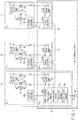
FIG. 1 is a diagram showing a structure of an embodiment. -
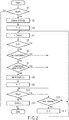
FIG. 2 is a flowchart showing control which a master unit executes in the embodiment. -
FIG. 3 is a flowchart showing control which the master unit and the slave units execute in the embodiment. -
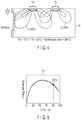
FIG. 4 is a diagram showing a partial load factor of each air conditioner in a case where power linkage control is not executed in the embodiment. -
FIG. 5 is a graph showing a relationship between a partial load factor and the energy efficiency of the air conditioner on a window side inFIG. 4 . -
FIG. 6 is a graph showing a relationship between a partial load factor and the energy efficiency of the air conditioner on a non-window side inFIG. 4 . -
FIG. 7 is a diagram showing a partial load factor of each air conditioner in a case where power linkage control is executed in the embodiment. -
FIG. 8 is a graph showing a relationship between the partial load factor and the energy efficiency of the air conditioner on a window side inFIG. 7 . -
FIG. 9 is a graph showing a relationship between the partial load factor and the energy efficiency of the air conditioner on a non-window side inFIG. 7 . -
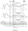
FIG. 10 is a chart showing variation of the partial load factor of each air conditioner and variation in the indoor temperature in the embodiment. - One of embodiments will be described hereinafter with reference to the accompanying drawings.
- As shown in
FIG. 1 ,indoor units 20 of a plurality ofair conditioners - An
air conditioner 1a serving as a master unit comprises a heat-pump-type refrigerating cycle formed by sequentially connecting acompressor 11, a four-way valve 12, anoutdoor heat exchanger 13, a decompression device, for example,electric expansion valve 14, and anindoor heat exchanger 21 by piping. - At the cooling operation, a refrigerant discharged from the
compressor 11 flows into the outdoor heat exchanger (condenser) 13 through the four-way valve 12, the refrigerant flowing out from theoutdoor heat exchanger 13 flows into the indoor heat exchanger (evaporator) 21 through theelectric expansion valve 14, and the refrigerant flowing out from theindoor heat exchanger 21 is sucked into thecompressor 11 through the four-way valve 12. - At the heating operation, the refrigerant discharged from the
compressor 11 flows into the indoor heat exchanger (condenser) 21 through the four-way valve 12, the refrigerant flowing out from theindoor heat exchanger 21 flows into the outdoor heat exchanger (evaporator) 13 through theelectric expansion valve 14, and the refrigerant flowing out from theoutdoor heat exchanger 13 is sucked into thecompressor 11 through the four-way valve 12, as represented by arrows, by change of the flow path of the four-way valve 12. - An
outdoor fan 15 sucking outdoor air and passing the outdoor air to theoutdoor heat exchanger 13 is arranged in the vicinity of theoutdoor heat exchanger 13, and an outsideair temperature sensor 16 detecting an outside air temperature To is arranged in a suction air path of theoutdoor fan 15. Anindoor fan 22 sucking the indoor air of the air-conditioned area and passing the air through theindoor heat exchanger 21 is arranged in the vicinity of theindoor heat exchanger 21, and anindoor temperature sensor 23 detecting a temperature (referred to as an indoor temperature) Ta of the indoor air is arranged in a suction path of theindoor fan 22. - The
compressor 11, the four-way valve 12, theoutdoor heat exchanger 13, theelectric expansion valve 14, theoutdoor fan 15, and the outsideair temperature sensor 16 are accommodated in anoutdoor unit 10 together with anoutdoor controller 18a, and theindoor unit 21, theindoor fan 22, and theindoor temperature sensor 23 are accommodated in theindoor unit 20 together with anindoor controller 24a. Theoutdoor controller 18a and theindoor controller 24a are interconnected through aserial signal line 31 synchronous with a power supply voltage, and a remote control-type operator (simply referred to as a remote controller) 33 for the operation and for operating condition setting is connected to theindoor controller 24a through acable 32. Theremote controller 33 is attached onto a wall surface of the air-conditioned area or the like and can easily be controlled by the user. - The
outdoor controller 18a is composed of a microcomputer and peripheral circuits thereof, controls thecompressor 11, the four-way valve 12, theelectric expansion valve 14, and theoutdoor fan 15 in response to instructions from theindoor controller 24a, and sends data such as the detection temperature (referred to as an outside air temperature) To of the outsideair temperature sensor 16 and the detection temperature (referred to as a heat exchanger temperature) Te of a heatexchange temperature sensor 17 to theindoor controller 24a by aserial signal line 31. - The
indoor controller 24a is composed of a microcomputer and peripheral circuits thereof and controls the operation of theair conditioner 1a in accordance with control of theremote controller 33, the operating condition set by theremote controller 33, data transmitted from theoutdoor controller 18a, and the like. That is, theindoor controller 24a recognizes a difference ΔT (= | Ts - Ta |) between a target indoor temperature Ts set with theremote controller 33 and a detected temperature (indoor temperature) Ta of theindoor temperature sensor 23 as air conditioning load of theair conditioner 1a, and executes indoor temperature control to control a capacity (operation frequency) of thecompressor 11, i.e., an air conditioning capacity of theair conditioner 1a such that the air conditioning load ΔT becomes zero, i.e., the indoor temperature Ta becomes the target indoor temperature Ts. - A
bus line 40 for control and for data transmission is connected between theindoor controller 24a andindoor controllers 24b to 24n. -
Air conditioners 1b to In are merely different from theair conditioner 1a with respect to a feature of includingoutdoor controllers 18b to 18n and theindoor controllers 24b to 24n and the basic structure thereof is the same as that of theair conditioner 1a. - The
indoor controllers 24b to 24n are composed of microcomputers and peripheral circuits thereof and control the operations of therespective air conditioners 1b to In in response to the data transmitted from the respectiveoutdoor controllers 18b to 18n and the instruction from theindoor controller 24a. That is, the difference ΔT (= | Ts - Ta |) between the target indoor temperature Ts set with theremote controller 33 and the detected temperature (indoor temperature) Ta of eachindoor temperature sensor 23 is recognized as the air conditioning load of each of theair conditioners 1b to In, and the capacities (operation frequencies) of therespective compressors 11, i.e., the air conditioning capacities of theair conditioners 1b to In are controlled, respectively, such that the air conditioning loads ΔT become zero. - When a group control mode of controlling the
air conditioners remote controller 33, theindoor controller 24a of theair conditioner 1a functions as the master unit which is the center of the control, and theremaining air conditioners 1b to In and theindoor controllers 24b to 24n function as slave units following the instructions of the master unit. - The
indoor controller 24a of theair conditioner 1a comprises a first control section C1, a second control section C2, a third control section C3, and a fourth control section C4 as main functions relating to the power linkage of the master unit and the slave units. - The first control section C1 executes communication with the
indoor controllers 24a to 24n regularly as needed through thedata bus line 40. - When the air conditioning capacity of the
air conditioners 1b to In is detected by communication of the first control section C1 and the maximum air conditioning capacity (partial load factor L to be described later) of the air conditioning capacities of theair conditioner 1a and theair conditioners 1b to In is more than or equal to a set value and when a difference between the maximum air conditioning capacity and the minimum air conditioning capacity is more than or equal to a predetermined value, the second control section C2 gradually inhibits the maximum air conditioning capacity by a predetermined value (for example, 5%) and entrusts the operation of the remaining air conditions except the air conditioner which is targeted for the inhibition with the processing of air conditioning load ΔT' corresponding to the inhibition of this air conditioning capacity, by determining that the balance of high and low levels of each air conditioning load ΔT relating to theair conditioners 1a to In is not desirable for energy efficiency and should be solved. This control is referred to as power linkage control. That is, one or more remaining air conditioners except the air conditioner which is targeted for the inhibition of the air conditioning capacity takes in the air conditioning load ΔT' corresponding to the inhibition of the air conditioning capacity, additionally and naturally, as the increase in the air conditioning load ΔT of the air conditioner and processes the taken air conditioning load ΔT' together with the original air conditioning load ΔT by temporary increase of the course-like air conditioning capacity under normal indoor temperature control of the air conditioner. When remaining air conditioners except the air conditioner which is targeted for the inhibition of the air conditioning capacity is a plurality of air conditioners, the air conditioning load ΔT' is added in a state of being appropriately distributed to a plurality of air conditioners. Incidentally, at the inhibition of the air conditioning capacity, this second control section C2 determines the air conditioning capacity lower than the air conditioning capacity (the above-mentioned maximum air conditioning capacity) at the time of starting the inhibition by a predetermined value (for example, 20%) as a limit value (upper limit load factor Ls to be described later) of inhibition, and gradually inhibits the maximum air conditioning capacity toward the limit value by each predetermined value (5%). - When the air conditioning load ΔT of the air conditioner targeted for the inhibition becomes higher than or equal to the threshold value while the air conditioning capacity is being inhibited by the second control section C2, the third control section C3 gradually increases the air conditioning capacity which is being inhibited, toward a value corresponding to the current air conditioning load ΔT of the air conditioner targeted for the inhibition.
- Incidentally, more specifically, when the air conditioning load ΔT of the air conditioner targeted for the inhibition continues a condition more than or equal to a first threshold (for example, 2°C) for a certain time (for example, 30 minutes) or reaches a second threshold value (> first threshold value) higher than the first threshold value, while the air conditioning capacity is being inhibited by the second control section C2, the third control section C3 gradually increases the air conditioning capacity which is being inhibited toward a value corresponding to the current air conditioning load ΔT of the air conditioner targeted for the inhibition by each predetermined value (5%) .
- When the
remote control 33 is operated while the air conditioning capacity is being inhibited by the second control section C2, the fourth control section C4 gradually increases the air conditioning capacity which is being inhibited toward a value corresponding to the current air conditioning load ΔT of the air conditioner targeted for the inhibition, similarly to the third control section C3. - The control which the
indoor controller 24a of the master unit executes will be described with reference to a flowchart ofFIG. 2 . Steps S1, S2 ... in the flowchart will be simply referred to as S1, S2 ... - When the start control of the cooling operation or the heating operation is executed with the remote controller 33 (YES in S1), the
indoor controller 24a instructs theindoor controllers 24b to 24n to start the operation and notifies theindoor controllers 24b to 24n of a target indoor temperature (also referred to as a setting temperature) Ts set with the operation of the remote controller 33 (S2). - Then, the
indoor controller 24a sets "0" to a control flag f that is an index of whether the power linkage control is being executed or not (S3) and detects each of the air conditioning capacities that theair conditioners 1a to In are currently exerting as a partial load factor L (%) (S4). The partial load factor L (%) refers to a rate of the air conditioning capacities that theair conditioners 1a to In actually exert to rated air conditioning capacities of therespective air conditioners 1a to 1n. - Then, since the control flag f is "0" at this time (YES in S5), the
indoor controller 24a selects a maximum partial load factor (maximum air conditioning capacity) Lmax of the partial load factors (air conditioning capacities) L of therespective air conditioners 1a to In and determines whether the maximum partial load factor Lmax is in a high load factor condition of being higher than or equal to a set value (for example, 50%) or not (S6). - When the determination result of S6 is affirmative (YES in S6), the
indoor controller 24a selects a minimum partial load factor (minimum air conditioning capacity) Lmin of the partial load factors L of therespective air conditioners 1a to In and determines whether a difference ΔL (= Lmax - Lmin) between the maximum partial load factor Lmax and the minimum partial load factor Lmin is in a state of being higher than or equal to a determined value (for example, 20%) or not (S7). - When the determination result of S7 is affirmative (YES in S7), the
indoor controller 24a sets the partial load factor L lower than the maximum partial load factor Lmax by a predetermined value (for example, 20%) as an upper limit load factor of the power linkage control and notifies the indoor controller of the air conditioner (i.e., air conditioner targeted for the inhibition) running at the maximum partial load factor Lmax of the upper limit load factor Ls, by determining that the balance of the air conditioning loads ΔT of theair conditioners 1a to In is undesirable in energy efficiency and should be solved promptly (S8). - In accordance with the setting and notice of the upper limit load factor Ls, the
indoor controller 24a sets "1" to the control flag f (S9) and monitors the stop control of the remote controller 33 (S10). When the stop control of theremote controller 33 is not executed (NO in S10), theindoor controller 24a monitors an "end of inhibition" notice from the room controller of the air conditioner (i.e., the air conditioner targeted for the inhibition) running with the maximum partial load factor Lmax (S12). - When the "end of inhibition" notice is not sent (NO in S12), the
indoor controller 24a return to S4, detects the partial load factors L of therespective air conditioners 1a to In again (S4) and confirms the control flag f (S5). Since the control flag f at this time is "1" (NO in S5), theindoor controller 24a bypasses the processes of S6 to S9 and shifts to S10 and monitors the stop control of the remote controller 33 (S10). - When the "end of inhibition" notice is sent (YES in S12), the
indoor controller 24a sets "0" to the control flag f (S13). Then, theindoor controller 24a returns to S4, and detects the partial load factors L of therespective air conditioners 1a to In again (S4), and confirms the control flag f (S5). Since the control flag f at this time is "0" (YES in S5), theindoor controller 24a repeats the processes of S6 to S10. - When the stop control of the
remote controller 33 is executed (YES in S10), theindoor controller 24a instructs theindoor controllers 24b to 24n to stop the operation (S11). - The control executed by the
indoor controller 24a of the master unit and theindoor controllers 24b to 24n of the slave units will be described with reference to a flowchart ofFIG. 3 . - When the instruction to start the operation is sent (YES in S21), the
indoor controllers 24a to 24n start the operations ofair conditioners 1a to In (S22). Then, theindoor controllers 24a to 24n detect a difference ΔT (= | Ta - Ts |) between the detected temperature (indoor temperature) Ta of eachindoor temperature sensor 23 and the target indoor temperature Ts as their respective air conditioning loads ΔT, and control the partial load factors (air conditioning capacities) L of theair conditioners 1a to In in accordance with the air conditioning loads ΔT, respectively (S23). - When a certain time, for example, 15 minutes have elapsed since the start of the operation and the operations of the
air conditioners 1a to In become stable (YES in S24), theroom controllers 24a to 24n monitor whether the upper limit load factor Ls is set and notified or not (S25). When the upper limit load factor Ls is not set and notified (NO in S25), theindoor controllers 24a to 24n monitor whether the instruction to stop the operation is sent or not (S35). - When the instruction to stop the operation is not sent (NO in S35), the
indoor controllers 24a to 24n return to the process of S25 and monitors again whether the upper limit load factor Ls is set and notified or not (S25). When the instruction to stop the operation is sent (YES in S35), theindoor controllers 24a to 24n stop the operations of theair conditioners 1a to In (S36) . - The control in a case where, for example, the air conditioning load ΔT of the
air conditioner 1b increases rapidly and the partial load factor L of theair conditioner 1b becomes the maximum partial load factor Lmax accordingly will be described below. - When the maximum partial load factor Lmax is in the high load factor state of being higher than or equal to the set value (YES in S6) and when the difference ΔT between the maximum partial load factor Lmax and the minimum partial load factor Lmin is in a state of being higher than or equal to the determined value (S7), the upper limit load factor Ls is set in the
room controller 24a and is notified from theindoor controller 24a to theroom controller 24b (S8). - When receiving the notice of the upper limit load factor Ls from the
indoor controller 24a (YES in S25), theindoor controller 24b compares the upper limit load factor Ls with the partial load factor L (= Lmax) of theair conditioner 1b (S26). When the partial load factor L of theair conditioner 1b is higher than the upper limit load factor Ls (YES in S26), theindoor controller 24b inhibits the partial load factor L of theair conditioner 1b by a predetermined value (5%) (S27) . - In this inhibition, the air conditioning load ΔT' corresponding to the inhibition of the partial load factor L, of the air conditioning load ΔT of
air conditioner 1b, is not processed in theair conditioner 1b. The processing of this air conditioning load ΔT' is entrusted to the operations of theair conditioners 1a and 1c to 1n present in the same air-conditioned area R. - That is, the
air conditioners 1a and 1c to 1n take in air conditioning loads ΔT' untreated by inhibiting the partial load factor L of theair conditioner 1b, as the increase of the air conditioning loads ΔT of therespective air conditioners 1a and 1c to 1n, additionally and naturally, and process the taken air conditioning loads ΔT' together with the respective original air conditioning loads ΔT by temporary increase of each partial load factor L caused by the normal indoor temperature control of theair conditioners 1a and 1c to 1n. In this case, theair conditioners 1a and 1c to 1n only continue normal basic operations to control the respective partial load factors L in accordance with the respective air conditioning loads ΔT. - When 15 minutes have elapsed since start of the inhibition of the partial load factor L of the
air conditioner 1b (YES in S28), theindoor controller 24b discriminates whether the air conditioning load ΔT of theair conditioner 1b continues the state of being higher than or equal to the first threshold value (2°C) for a certain time (30 minutes) or not (S29). When the determination result is negative (NO in S29), theindoor controller 24b determines whether the air conditioning load ΔT of theair conditioner 1b reaches a second threshold value (3°C) and continues the state for a predetermined time (1 minute) or not (S30). When the determination result is negative (NO in S30), theindoor controller 24b determines whether theremote controller 33 is operated or not (S31). When the determination result is negative (NO in S31), theindoor controller 24b returns to S26 and compares the partial load factor L with the upper limit load factor Ls again (S26). - When the partial load factor L is higher than the upper limit load factor Ls (YES in S26), the
indoor controller 24b further inhibits the partial load factor L by a predetermined value (5%) (S27) and shifts to the determinations of S28 to S31. When all the determination results of S29, S30, and S31 are negative, inhibiting the partial load factor L by the predetermined value (5%) in S27 is repeated every 15 minutes. - When the inhibition advances and the partial load factor L becomes lower than or equal to the upper limit load factor Ls (NO in S26), the
room controller 24b shifts to the determination of S29 without executing the processes of S27 and S28, and waits for either of the determination results of S30 and S31 being affirmative while keeping the inhibited state of the partial load factor L. - When the air conditioning load ΔT of the
air conditioner 1b continues in the state of being higher than or equal to the first (2°C) for a certain time (30 minutes) (YES in S29), theindoor controller 24b increases the partial load factor L which is being inhibited, by a predetermined value (5%), toward a value corresponding to the current air conditioning load ΔT of theair conditioner 1b targeted for inhibition, by determining that the indoor temperature Ta detected by theair conditioner 1b can hardly be maintained at the target indoor temperature Ts in the condition that the capacity of theair conditioner 1b is slightly short (32). - When the air conditioning load ΔT of the
air conditioner 1b exceeds the first threshold value (2°C) and reaches the second threshold value (3°C) and the state continues for a predetermined time (1 minute) (NO in S29 and YES in S30), theindoor controller 24b increases the partial load factor L which is being inhibited, by a predetermined value (5%), toward a value corresponding to the current air conditioning load ΔT of theair conditioner 1b targeted for inhibition, by determining that shortage of the capacity of theair conditioner 1b is serious and the room temperature Ta at theroom controller 24b cannot be maintained at the target indoor temperature Ts (32). - In the cooling, since even a small rise in the indoor temperature Ta causes unpleasant feeling, the determination processes of S29 and S30 relating to the variation of the air conditioning load ΔT are essential. In the heating, since a small decrease in the indoor temperature Ta does not cause unpleasant feeling, the processes of S29 and S30 relating to the variation of the air conditioning load ΔT do not need to be executed.
- When any type of operation to the
remote controller 33 is executed by a resident of the air-conditioned area R (NO in S29, NO in S30, and YES in S31), theindoor controller 24b increases the partial load factor L which is being inhibited, by a predetermined value (5%), toward a value corresponding to the current air conditioning load ΔT of theair conditioner 1b targeted for inhibition, by determining that the comfortability of the air-conditioned area R becomes worse (S32). - Following the increase of the partial load factor L in S32, the
indoor controller 24b determines whether the increased partial load factor L reaches the value corresponding to the current air conditioning load ΔT of theair conditioner 1b targeted for control or not (S33). When the determination result is negative (NO in S33), theindoor controller 24b repeats the increase of the partial load factor L in S32 (S32). - When the determination result is affirmative (YES in S33), the
indoor controller 24b notifies theindoor controller 24a of "end of inhibition" (S34) and monitors the instruction to stop the operation from theindoor controller 24a (S35). When the instruction to stop the operation is not sent (NO in S35), theindoor controller 24b returns to S25 and monitors whether a new upper limit load factor Ls is set and notified or not (S25). When the instruction to stop the operation is sent (YES in S35), theindoor controller 24b stops the operation of theair conditioner 1b (S36). - As described above, when the air conditioning load ΔT of the air conditioner 1b increases rapidly and the partial load factor L (= Lmax) of the air conditioner 1b increases in a high load factor state of being higher than or equal to the set value and when the difference ΔL between the partial load factor L (= Lmax) and the minimum partial load factor Lmin of the air conditioner 1b is in the state of being higher than or equal to the predetermined value (20%), the partial load factor L of the air conditioner 1b is inhibited and the air conditioning load ΔT' corresponding to the inhibition of the partial load factor L is processed by the basic operation under the normal indoor temperature control of the remaining air conditioners 1a and 1c to 1n except the air conditioner 1b targeted for inhibition, by determining that the balance of the air conditioning loads ΔT of the respective air conditioners 1a to 1n is undesirable in energy efficiency and should be solved promptly, inhibits partial load factor L of air conditioner 1b and, therefore, even if the air conditioning load ΔT of the air conditioner 1b increases rapidly, the appropriate air conditioning capacity that is not delayed in response to the rapid increase of the air conditioning load ΔT of the air conditioner 1b can be obtained while preventing degradation of the energy efficiency of the air conditioner 1b and while maintaining the desirable energy efficiencies of the air conditioners 1a and 1c to 1n. Comfortability of the air-conditioned area R is improved.
- when the partial load factor L (= Lmax) is inhibited, the inhibition is gradually executed by each predetermined value and, therefore, sudden decrease of the indoor temperature Ta of a place where the air conditioner targeted for inhibition is present can be prevented. Uncomfortable feeling is not given to the resident in the air-conditioned area R.
- When the partial load factor L (= Lmax) which is being inhibited increases toward the value corresponding to the current air conditioning load ΔT of the air conditioner targeted for inhibition, the increase is gradually executed by each predetermined value and, therefore, sudden increase of the power consumption of the air conditioner targeted for inhibition can be prevented.
- As shown in
FIG. 4 , when theair conditioner 1a is arranged at a place near a window which is well exposed to solar light and theair conditioner 1b is arranged at a place remote from the window and theseair conditioners air conditioner 1a becomes larger than the air conditioning load ΔT of theair conditioner 1b. In accordance with this, theair conditioner 1a runs with the high air conditioning capacity of, for example, partial load factor L = 80%, and theair conditioner 1b runs with the low air conditioning capacity of, for example, partial load factor L = 30%. In this case, as shown inFIG. 5 andFIG. 6 , the energy efficiency of theair conditioner 1b running with a low air conditioning capacity is desirable, but the energy efficiency of theair conditioner 1a running with a high air conditioning capacity decreases. - When the power linkage control of the embodiment is executed in such a situation, the
air conditioner 1a shifts from the running of the previous partial load factor L = 80% to the running with the middle air conditioning capacity of the partial load factor L = 60%, and theair conditioner 1b shifts from the running of the previous partial load factor L = 30% to the running with the middle air conditioning capacity of the partial load factor L = 50%, as shown inFIG. 7 . In this case, as shown inFIG. 8 and FIG. 9 , the energy efficiency of theair conditioner 1a increases and becomes desirable, and the energy efficiency of theair conditioner 1b is also kept in a preferable condition. That is, the overall energy efficiency of the air conditioning apparatus is improved. - Comparison of variations of the partial load factors L of the
respective air conditioners air conditioner 1a is arranged are shown inFIG. 10 in a case where the power linkage control of the embodiment is provided and a case where the power linkage control is not provided is shown inFIG. 10 . - In the above-described embodiment, when the maximum partial load factor Lmax is higher than or equal to the set value and the difference between the maximum partial load factor Lmax and the minimum partial load factor Lmin is larger than or equal to the predetermined value, the maximum partial load factor Lmax is inhibited but, when the maximum partial load factor Lmax is higher than or equal to the set value, the maximum partial load factor Lmax may be promptly controlled to be inhibited.
- The above embodiments and modified example described herein have been presented by way of example only, and are not intended to limit the scope of the inventions. Indeed, the novel embodiments described herein may be embodied in a variety of other forms; furthermore, various omissions, substitutions and changes in the form of the embodiment described herein may be made without departing from the spirit of the invention. The accompanying claims and their equivalents are intended to cover such forms or modifications as would fall within the scope and spirit of the inventions.
- 1a to 1n. . . Air conditioner, 10. . . Outdoor unit, 11... Compressor, 13... Outdoor heat exchanger, 18a, 18b, ... 18n... Outdoor controller, 20... Indoor unit, 24a to 24n... Indoor controller, 33... Remote controller, 40... Bus line.
Claims (7)
- An air conditioning apparatus characterized by comprising:a plurality of air conditioners arranged in one same air-conditioned area to control air conditioning capacities in accordance with air conditioning loads, respectively; andcontroller configured to inhibiting the maximum air conditioning capacity when a maximum air conditioning capacity of the air conditioning capacity of each of the air conditioners is higher than or equal to a set value.
- The air conditioning apparatus of claim 1, characterized in that
one or more remaining air conditioners except the air conditioner targeted for the inhibition, of each of the air conditioners, processes the air conditioning load corresponding to the inhibition of the air conditioning capacity as the air conditioning load of the air conditioner. - The air conditioning apparatus of claim 1, characterized in that
the controller inhibits the maximum air conditioning capacity when the maximum air conditioning capacity is higher than or equal to the set value and a difference between the maximum air conditioning capacity and a minimum air conditioning capacity is larger than or equal to a predetermined value. - The air conditioning apparatus of claim 1, characterized in that
the controller gradually inhibits the maximum air conditioning capacity by each predetermined value. - The air conditioning apparatus of claim 1, characterized in that
when the air conditioning load of the air conditioner targeted for the inhibition becomes higher than or equal to a threshold value while inhibiting the maximum air conditioning capacity, the controller gradually increases the air conditioning capacity which is being inhibited, toward a value corresponding to the air conditioning load of the air conditioner targeted for the inhibition. - The air conditioning apparatus of claim 1, characterized in that
when the air conditioning load of the air conditioner targeted for the inhibition continues in a state of being higher than or equal to a first threshold value or reaches a second threshold value higher than the first threshold value while inhibiting the maximum air conditioning capacity, the controller gradually increases the air conditioning capacity which is being inhibited, toward a value corresponding to the air conditioning load of the air conditioner targeted for the inhibition. - The air conditioning apparatus of claim 1, characterized in thateach of the air conditioners controls the air conditioning capacity such that each suction air temperature becomes a target indoor temperature set with an operation unit, andwhen the operation unit is operated while inhibiting the maximum air conditioning capacity, the controller gradually increases the air conditioning capacity which is being inhibited, toward a value corresponding to the air conditioning load of the air conditioner targeted for the inhibition.
Applications Claiming Priority (2)
| Application Number | Priority Date | Filing Date | Title |
|---|---|---|---|
| JP2018229107 | 2018-12-06 | ||
| PCT/JP2019/047475 WO2020116530A1 (en) | 2018-12-06 | 2019-12-04 | Air conditioning device |
Publications (3)
| Publication Number | Publication Date |
|---|---|
| EP3892929A1 true EP3892929A1 (en) | 2021-10-13 |
| EP3892929A4 EP3892929A4 (en) | 2022-08-17 |
| EP3892929B1 EP3892929B1 (en) | 2025-09-17 |
Family
ID=70974720
Family Applications (1)
| Application Number | Title | Priority Date | Filing Date |
|---|---|---|---|
| EP19893827.6A Active EP3892929B1 (en) | 2018-12-06 | 2019-12-04 | Air conditioning device |
Country Status (4)
| Country | Link |
|---|---|
| EP (1) | EP3892929B1 (en) |
| JP (1) | JP7438976B2 (en) |
| CN (1) | CN113167493A (en) |
| WO (1) | WO2020116530A1 (en) |
Family Cites Families (11)
| Publication number | Priority date | Publication date | Assignee | Title |
|---|---|---|---|---|
| JPS61282750A (en) * | 1985-06-07 | 1986-12-12 | Hitachi Ltd | Method of operating air conditioner |
| JP3171456B2 (en) * | 1991-07-09 | 2001-05-28 | 東芝キヤリア株式会社 | Air conditioner operation control method |
| JP2007071401A (en) * | 2005-09-02 | 2007-03-22 | Hitachi Ltd | Air conditioner |
| JP2007271112A (en) * | 2006-03-30 | 2007-10-18 | Mitsubishi Electric Corp | Air conditioner |
| CN101344300A (en) * | 2007-07-13 | 2009-01-14 | 张亦翔 | Power factor compensation type air conditioner integral power economizer |
| CN101498494B (en) * | 2008-01-31 | 2010-06-09 | 上海南区节电科技开发有限公司 | An economical operation method of central air-conditioning system |
| JP5029913B2 (en) * | 2008-07-04 | 2012-09-19 | 株式会社日立プラントテクノロジー | Air conditioning system and control method thereof |
| JP4667496B2 (en) * | 2008-11-17 | 2011-04-13 | 三菱電機株式会社 | Air conditioner |
| JP5014376B2 (en) * | 2009-04-30 | 2012-08-29 | 三菱電機株式会社 | Air conditioning system |
| JP4980407B2 (en) | 2009-10-21 | 2012-07-18 | 三菱電機株式会社 | Air conditioner control device, refrigeration device control device |
| JP5479133B2 (en) * | 2010-01-29 | 2014-04-23 | 三洋電機株式会社 | Air conditioning controller |
-
2019
- 2019-12-04 EP EP19893827.6A patent/EP3892929B1/en active Active
- 2019-12-04 JP JP2020559983A patent/JP7438976B2/en active Active
- 2019-12-04 CN CN201980080143.9A patent/CN113167493A/en active Pending
- 2019-12-04 WO PCT/JP2019/047475 patent/WO2020116530A1/en not_active Ceased
Also Published As
| Publication number | Publication date |
|---|---|
| JPWO2020116530A1 (en) | 2021-09-27 |
| CN113167493A (en) | 2021-07-23 |
| WO2020116530A1 (en) | 2020-06-11 |
| EP3892929A4 (en) | 2022-08-17 |
| EP3892929B1 (en) | 2025-09-17 |
| JP7438976B2 (en) | 2024-02-27 |
Similar Documents
| Publication | Publication Date | Title |
|---|---|---|
| KR100468917B1 (en) | Multi-type air conditioner | |
| AU2014253572B2 (en) | Air-conditioning apparatus | |
| EP1536186B1 (en) | Air conditioner | |
| US10670296B2 (en) | System and method of adjusting compressor modulation range based on balance point detection of the conditioned space | |
| EP1862745B1 (en) | Air conditioner | |
| CN100472141C (en) | Multi-channel air conditioner peak power control system and its control method | |
| CN108895601B (en) | Central air conditioner group control method based on magnetic suspension host | |
| WO2018214766A1 (en) | Control method and control device for frequency change air conditioner, and frequency change air conditioner | |
| JP5940295B2 (en) | Air conditioning control system and air conditioning control method | |
| CN113483446B (en) | A kind of multi-connected air conditioner refrigeration operation method | |
| JP5642121B2 (en) | Air conditioner | |
| WO2023202063A1 (en) | Active redundant air conditioning unit and control method | |
| JP2010032073A (en) | Air-conditioning system | |
| KR101554180B1 (en) | Operation control device and method of multi air conditioning system | |
| KR100444971B1 (en) | Multi-chamber type air conditioner and method for controlling electric expansion valve thereof | |
| JP5750308B2 (en) | Air conditioner control system | |
| EP1467099B1 (en) | Separate-type air conditioner | |
| EP3892929B1 (en) | Air conditioning device | |
| US20150362231A1 (en) | Gas heat pump air conditioning system | |
| JP3526393B2 (en) | Air conditioner | |
| JP7100423B2 (en) | Cold water circulation system | |
| JPH07332730A (en) | Air conditioner | |
| WO2018105732A1 (en) | Heat medium circulation system and coolant circulation system | |
| CN202101372U (en) | Double-compressor refrigerating system and energy-saving optimizer thereof | |
| JPH10205851A (en) | Power demand control device for air conditioner |
Legal Events
| Date | Code | Title | Description |
|---|---|---|---|
| STAA | Information on the status of an ep patent application or granted ep patent |
Free format text: STATUS: THE INTERNATIONAL PUBLICATION HAS BEEN MADE |
|
| PUAI | Public reference made under article 153(3) epc to a published international application that has entered the european phase |
Free format text: ORIGINAL CODE: 0009012 |
|
| STAA | Information on the status of an ep patent application or granted ep patent |
Free format text: STATUS: REQUEST FOR EXAMINATION WAS MADE |
|
| 17P | Request for examination filed |
Effective date: 20210610 |
|
| AK | Designated contracting states |
Kind code of ref document: A1 Designated state(s): AL AT BE BG CH CY CZ DE DK EE ES FI FR GB GR HR HU IE IS IT LI LT LU LV MC MK MT NL NO PL PT RO RS SE SI SK SM TR |
|
| DAV | Request for validation of the european patent (deleted) | ||
| DAX | Request for extension of the european patent (deleted) | ||
| A4 | Supplementary search report drawn up and despatched |
Effective date: 20220720 |
|
| RIC1 | Information provided on ipc code assigned before grant |
Ipc: F24F 11/70 20180101ALI20220714BHEP Ipc: F24F 1/0003 20190101ALI20220714BHEP Ipc: F24F 140/50 20180101ALI20220714BHEP Ipc: F24F 11/54 20180101ALI20220714BHEP Ipc: F24F 11/46 20180101AFI20220714BHEP |
|
| STAA | Information on the status of an ep patent application or granted ep patent |
Free format text: STATUS: EXAMINATION IS IN PROGRESS |
|
| 17Q | First examination report despatched |
Effective date: 20231011 |
|
| GRAP | Despatch of communication of intention to grant a patent |
Free format text: ORIGINAL CODE: EPIDOSNIGR1 |
|
| STAA | Information on the status of an ep patent application or granted ep patent |
Free format text: STATUS: GRANT OF PATENT IS INTENDED |
|
| INTG | Intention to grant announced |
Effective date: 20250402 |
|
| GRAS | Grant fee paid |
Free format text: ORIGINAL CODE: EPIDOSNIGR3 |
|
| GRAA | (expected) grant |
Free format text: ORIGINAL CODE: 0009210 |
|
| STAA | Information on the status of an ep patent application or granted ep patent |
Free format text: STATUS: THE PATENT HAS BEEN GRANTED |
|
| AK | Designated contracting states |
Kind code of ref document: B1 Designated state(s): AL AT BE BG CH CY CZ DE DK EE ES FI FR GB GR HR HU IE IS IT LI LT LU LV MC MK MT NL NO PL PT RO RS SE SI SK SM TR |
|
| RAP3 | Party data changed (applicant data changed or rights of an application transferred) |
Owner name: CARRIER JAPAN CORPORATION |
|
| REG | Reference to a national code |
Ref country code: GB Ref legal event code: FG4D |
|
| REG | Reference to a national code |
Ref country code: CH Ref legal event code: EP |
|
| REG | Reference to a national code |
Ref country code: DE Ref legal event code: R096 Ref document number: 602019075963 Country of ref document: DE |
|
| REG | Reference to a national code |
Ref country code: IE Ref legal event code: FG4D |
|
| PGFP | Annual fee paid to national office [announced via postgrant information from national office to epo] |
Ref country code: DE Payment date: 20251126 Year of fee payment: 7 |
|
| PGFP | Annual fee paid to national office [announced via postgrant information from national office to epo] |
Ref country code: GB Payment date: 20251119 Year of fee payment: 7 |
|
| PG25 | Lapsed in a contracting state [announced via postgrant information from national office to epo] |
Ref country code: NO Free format text: LAPSE BECAUSE OF FAILURE TO SUBMIT A TRANSLATION OF THE DESCRIPTION OR TO PAY THE FEE WITHIN THE PRESCRIBED TIME-LIMIT Effective date: 20251217 |
|
| REG | Reference to a national code |
Ref country code: LT Ref legal event code: MG9D |
|
| PG25 | Lapsed in a contracting state [announced via postgrant information from national office to epo] |
Ref country code: FI Free format text: LAPSE BECAUSE OF FAILURE TO SUBMIT A TRANSLATION OF THE DESCRIPTION OR TO PAY THE FEE WITHIN THE PRESCRIBED TIME-LIMIT Effective date: 20250917 |
|
| PG25 | Lapsed in a contracting state [announced via postgrant information from national office to epo] |
Ref country code: HR Free format text: LAPSE BECAUSE OF FAILURE TO SUBMIT A TRANSLATION OF THE DESCRIPTION OR TO PAY THE FEE WITHIN THE PRESCRIBED TIME-LIMIT Effective date: 20250917 |
|
| PGFP | Annual fee paid to national office [announced via postgrant information from national office to epo] |
Ref country code: FR Payment date: 20251120 Year of fee payment: 7 |
|
| PG25 | Lapsed in a contracting state [announced via postgrant information from national office to epo] |
Ref country code: GR Free format text: LAPSE BECAUSE OF FAILURE TO SUBMIT A TRANSLATION OF THE DESCRIPTION OR TO PAY THE FEE WITHIN THE PRESCRIBED TIME-LIMIT Effective date: 20251218 |
|
| PG25 | Lapsed in a contracting state [announced via postgrant information from national office to epo] |
Ref country code: SE Free format text: LAPSE BECAUSE OF FAILURE TO SUBMIT A TRANSLATION OF THE DESCRIPTION OR TO PAY THE FEE WITHIN THE PRESCRIBED TIME-LIMIT Effective date: 20250917 |
|
| REG | Reference to a national code |
Ref country code: NL Ref legal event code: MP Effective date: 20250917 |
|
| PG25 | Lapsed in a contracting state [announced via postgrant information from national office to epo] |
Ref country code: LV Free format text: LAPSE BECAUSE OF FAILURE TO SUBMIT A TRANSLATION OF THE DESCRIPTION OR TO PAY THE FEE WITHIN THE PRESCRIBED TIME-LIMIT Effective date: 20250917 |
|
| PG25 | Lapsed in a contracting state [announced via postgrant information from national office to epo] |
Ref country code: BG Free format text: LAPSE BECAUSE OF FAILURE TO SUBMIT A TRANSLATION OF THE DESCRIPTION OR TO PAY THE FEE WITHIN THE PRESCRIBED TIME-LIMIT Effective date: 20250917 |
|
| PG25 | Lapsed in a contracting state [announced via postgrant information from national office to epo] |
Ref country code: RS Free format text: LAPSE BECAUSE OF FAILURE TO SUBMIT A TRANSLATION OF THE DESCRIPTION OR TO PAY THE FEE WITHIN THE PRESCRIBED TIME-LIMIT Effective date: 20251217 |
|
| PG25 | Lapsed in a contracting state [announced via postgrant information from national office to epo] |
Ref country code: NL Free format text: LAPSE BECAUSE OF FAILURE TO SUBMIT A TRANSLATION OF THE DESCRIPTION OR TO PAY THE FEE WITHIN THE PRESCRIBED TIME-LIMIT Effective date: 20250917 |
|
| REG | Reference to a national code |
Ref country code: AT Ref legal event code: MK05 Ref document number: 1838577 Country of ref document: AT Kind code of ref document: T Effective date: 20250917 |
|
| PG25 | Lapsed in a contracting state [announced via postgrant information from national office to epo] |
Ref country code: SM Free format text: LAPSE BECAUSE OF FAILURE TO SUBMIT A TRANSLATION OF THE DESCRIPTION OR TO PAY THE FEE WITHIN THE PRESCRIBED TIME-LIMIT Effective date: 20250917 |
|
| PG25 | Lapsed in a contracting state [announced via postgrant information from national office to epo] |
Ref country code: ES Free format text: LAPSE BECAUSE OF FAILURE TO SUBMIT A TRANSLATION OF THE DESCRIPTION OR TO PAY THE FEE WITHIN THE PRESCRIBED TIME-LIMIT Effective date: 20250917 |
|
| PG25 | Lapsed in a contracting state [announced via postgrant information from national office to epo] |
Ref country code: AT Free format text: LAPSE BECAUSE OF FAILURE TO SUBMIT A TRANSLATION OF THE DESCRIPTION OR TO PAY THE FEE WITHIN THE PRESCRIBED TIME-LIMIT Effective date: 20250917 |
|
| PG25 | Lapsed in a contracting state [announced via postgrant information from national office to epo] |
Ref country code: IT Free format text: LAPSE BECAUSE OF FAILURE TO SUBMIT A TRANSLATION OF THE DESCRIPTION OR TO PAY THE FEE WITHIN THE PRESCRIBED TIME-LIMIT Effective date: 20250917 Ref country code: RO Free format text: LAPSE BECAUSE OF FAILURE TO SUBMIT A TRANSLATION OF THE DESCRIPTION OR TO PAY THE FEE WITHIN THE PRESCRIBED TIME-LIMIT Effective date: 20250917 |
|
| PG25 | Lapsed in a contracting state [announced via postgrant information from national office to epo] |
Ref country code: IS Free format text: LAPSE BECAUSE OF FAILURE TO SUBMIT A TRANSLATION OF THE DESCRIPTION OR TO PAY THE FEE WITHIN THE PRESCRIBED TIME-LIMIT Effective date: 20260117 |
|
| PG25 | Lapsed in a contracting state [announced via postgrant information from national office to epo] |
Ref country code: CZ Free format text: LAPSE BECAUSE OF FAILURE TO SUBMIT A TRANSLATION OF THE DESCRIPTION OR TO PAY THE FEE WITHIN THE PRESCRIBED TIME-LIMIT Effective date: 20250917 Ref country code: PT Free format text: LAPSE BECAUSE OF FAILURE TO SUBMIT A TRANSLATION OF THE DESCRIPTION OR TO PAY THE FEE WITHIN THE PRESCRIBED TIME-LIMIT Effective date: 20260119 |
|
| PG25 | Lapsed in a contracting state [announced via postgrant information from national office to epo] |
Ref country code: PL Free format text: LAPSE BECAUSE OF FAILURE TO SUBMIT A TRANSLATION OF THE DESCRIPTION OR TO PAY THE FEE WITHIN THE PRESCRIBED TIME-LIMIT Effective date: 20250917 |
|
| PG25 | Lapsed in a contracting state [announced via postgrant information from national office to epo] |
Ref country code: SK Free format text: LAPSE BECAUSE OF FAILURE TO SUBMIT A TRANSLATION OF THE DESCRIPTION OR TO PAY THE FEE WITHIN THE PRESCRIBED TIME-LIMIT Effective date: 20250917 Ref country code: EE Free format text: LAPSE BECAUSE OF FAILURE TO SUBMIT A TRANSLATION OF THE DESCRIPTION OR TO PAY THE FEE WITHIN THE PRESCRIBED TIME-LIMIT Effective date: 20250917 |