EP3892875A1 - Flushing of a touchdown bearing - Google Patents
Flushing of a touchdown bearing Download PDFInfo
- Publication number
- EP3892875A1 EP3892875A1 EP21162336.8A EP21162336A EP3892875A1 EP 3892875 A1 EP3892875 A1 EP 3892875A1 EP 21162336 A EP21162336 A EP 21162336A EP 3892875 A1 EP3892875 A1 EP 3892875A1
- Authority
- EP
- European Patent Office
- Prior art keywords
- compressor
- working fluid
- touchdown bearing
- bearing
- touchdown
- Prior art date
- Legal status (The legal status is an assumption and is not a legal conclusion. Google has not performed a legal analysis and makes no representation as to the accuracy of the status listed.)
- Granted
Links
Images


Classifications
-
- F—MECHANICAL ENGINEERING; LIGHTING; HEATING; WEAPONS; BLASTING
- F04—POSITIVE - DISPLACEMENT MACHINES FOR LIQUIDS; PUMPS FOR LIQUIDS OR ELASTIC FLUIDS
- F04D—NON-POSITIVE-DISPLACEMENT PUMPS
- F04D29/00—Details, component parts, or accessories
- F04D29/05—Shafts or bearings, or assemblies thereof, specially adapted for elastic fluid pumps
- F04D29/056—Bearings
- F04D29/058—Bearings magnetic; electromagnetic
-
- F—MECHANICAL ENGINEERING; LIGHTING; HEATING; WEAPONS; BLASTING
- F16—ENGINEERING ELEMENTS AND UNITS; GENERAL MEASURES FOR PRODUCING AND MAINTAINING EFFECTIVE FUNCTIONING OF MACHINES OR INSTALLATIONS; THERMAL INSULATION IN GENERAL
- F16C—SHAFTS; FLEXIBLE SHAFTS; ELEMENTS OR CRANKSHAFT MECHANISMS; ROTARY BODIES OTHER THAN GEARING ELEMENTS; BEARINGS
- F16C32/00—Bearings not otherwise provided for
- F16C32/04—Bearings not otherwise provided for using magnetic or electric supporting means
- F16C32/0406—Magnetic bearings
- F16C32/044—Active magnetic bearings
- F16C32/0442—Active magnetic bearings with devices affected by abnormal, undesired or non-standard conditions such as shock-load, power outage, start-up or touchdown
-
- F—MECHANICAL ENGINEERING; LIGHTING; HEATING; WEAPONS; BLASTING
- F04—POSITIVE - DISPLACEMENT MACHINES FOR LIQUIDS; PUMPS FOR LIQUIDS OR ELASTIC FLUIDS
- F04C—ROTARY-PISTON, OR OSCILLATING-PISTON, POSITIVE-DISPLACEMENT MACHINES FOR LIQUIDS; ROTARY-PISTON, OR OSCILLATING-PISTON, POSITIVE-DISPLACEMENT PUMPS
- F04C2/00—Rotary-piston machines or pumps
- F04C2/02—Rotary-piston machines or pumps of arcuate-engagement type, i.e. with circular translatory movement of co-operating members, each member having the same number of teeth or tooth-equivalents
- F04C2/025—Rotary-piston machines or pumps of arcuate-engagement type, i.e. with circular translatory movement of co-operating members, each member having the same number of teeth or tooth-equivalents the moving and the stationary member having co-operating elements in spiral form
-
- F—MECHANICAL ENGINEERING; LIGHTING; HEATING; WEAPONS; BLASTING
- F04—POSITIVE - DISPLACEMENT MACHINES FOR LIQUIDS; PUMPS FOR LIQUIDS OR ELASTIC FLUIDS
- F04D—NON-POSITIVE-DISPLACEMENT PUMPS
- F04D17/00—Radial-flow pumps, e.g. centrifugal pumps; Helico-centrifugal pumps
- F04D17/08—Centrifugal pumps
- F04D17/10—Centrifugal pumps for compressing or evacuating
-
- F—MECHANICAL ENGINEERING; LIGHTING; HEATING; WEAPONS; BLASTING
- F04—POSITIVE - DISPLACEMENT MACHINES FOR LIQUIDS; PUMPS FOR LIQUIDS OR ELASTIC FLUIDS
- F04D—NON-POSITIVE-DISPLACEMENT PUMPS
- F04D25/00—Pumping installations or systems
- F04D25/02—Units comprising pumps and their driving means
- F04D25/06—Units comprising pumps and their driving means the pump being electrically driven
-
- F—MECHANICAL ENGINEERING; LIGHTING; HEATING; WEAPONS; BLASTING
- F04—POSITIVE - DISPLACEMENT MACHINES FOR LIQUIDS; PUMPS FOR LIQUIDS OR ELASTIC FLUIDS
- F04D—NON-POSITIVE-DISPLACEMENT PUMPS
- F04D29/00—Details, component parts, or accessories
- F04D29/04—Shafts or bearings, or assemblies thereof
- F04D29/046—Bearings
- F04D29/048—Bearings magnetic; electromagnetic
-
- F—MECHANICAL ENGINEERING; LIGHTING; HEATING; WEAPONS; BLASTING
- F04—POSITIVE - DISPLACEMENT MACHINES FOR LIQUIDS; PUMPS FOR LIQUIDS OR ELASTIC FLUIDS
- F04D—NON-POSITIVE-DISPLACEMENT PUMPS
- F04D29/00—Details, component parts, or accessories
- F04D29/05—Shafts or bearings, or assemblies thereof, specially adapted for elastic fluid pumps
- F04D29/056—Bearings
- F04D29/057—Bearings hydrostatic; hydrodynamic
-
- F—MECHANICAL ENGINEERING; LIGHTING; HEATING; WEAPONS; BLASTING
- F04—POSITIVE - DISPLACEMENT MACHINES FOR LIQUIDS; PUMPS FOR LIQUIDS OR ELASTIC FLUIDS
- F04D—NON-POSITIVE-DISPLACEMENT PUMPS
- F04D29/00—Details, component parts, or accessories
- F04D29/05—Shafts or bearings, or assemblies thereof, specially adapted for elastic fluid pumps
- F04D29/056—Bearings
- F04D29/059—Roller bearings
-
- F—MECHANICAL ENGINEERING; LIGHTING; HEATING; WEAPONS; BLASTING
- F04—POSITIVE - DISPLACEMENT MACHINES FOR LIQUIDS; PUMPS FOR LIQUIDS OR ELASTIC FLUIDS
- F04D—NON-POSITIVE-DISPLACEMENT PUMPS
- F04D29/00—Details, component parts, or accessories
- F04D29/06—Lubrication
- F04D29/063—Lubrication specially adapted for elastic fluid pumps
-
- F—MECHANICAL ENGINEERING; LIGHTING; HEATING; WEAPONS; BLASTING
- F04—POSITIVE - DISPLACEMENT MACHINES FOR LIQUIDS; PUMPS FOR LIQUIDS OR ELASTIC FLUIDS
- F04D—NON-POSITIVE-DISPLACEMENT PUMPS
- F04D29/00—Details, component parts, or accessories
- F04D29/58—Cooling; Heating; Diminishing heat transfer
- F04D29/5806—Cooling the drive system
-
- F—MECHANICAL ENGINEERING; LIGHTING; HEATING; WEAPONS; BLASTING
- F04—POSITIVE - DISPLACEMENT MACHINES FOR LIQUIDS; PUMPS FOR LIQUIDS OR ELASTIC FLUIDS
- F04D—NON-POSITIVE-DISPLACEMENT PUMPS
- F04D29/00—Details, component parts, or accessories
- F04D29/70—Suction grids; Strainers; Dust separation; Cleaning
- F04D29/701—Suction grids; Strainers; Dust separation; Cleaning especially adapted for elastic fluid pumps
- F04D29/703—Suction grids; Strainers; Dust separation; Cleaning especially adapted for elastic fluid pumps specially for fans, e.g. fan guards
-
- F—MECHANICAL ENGINEERING; LIGHTING; HEATING; WEAPONS; BLASTING
- F16—ENGINEERING ELEMENTS AND UNITS; GENERAL MEASURES FOR PRODUCING AND MAINTAINING EFFECTIVE FUNCTIONING OF MACHINES OR INSTALLATIONS; THERMAL INSULATION IN GENERAL
- F16C—SHAFTS; FLEXIBLE SHAFTS; ELEMENTS OR CRANKSHAFT MECHANISMS; ROTARY BODIES OTHER THAN GEARING ELEMENTS; BEARINGS
- F16C32/00—Bearings not otherwise provided for
- F16C32/04—Bearings not otherwise provided for using magnetic or electric supporting means
- F16C32/0406—Magnetic bearings
- F16C32/044—Active magnetic bearings
- F16C32/0474—Active magnetic bearings for rotary movement
-
- F—MECHANICAL ENGINEERING; LIGHTING; HEATING; WEAPONS; BLASTING
- F16—ENGINEERING ELEMENTS AND UNITS; GENERAL MEASURES FOR PRODUCING AND MAINTAINING EFFECTIVE FUNCTIONING OF MACHINES OR INSTALLATIONS; THERMAL INSULATION IN GENERAL
- F16C—SHAFTS; FLEXIBLE SHAFTS; ELEMENTS OR CRANKSHAFT MECHANISMS; ROTARY BODIES OTHER THAN GEARING ELEMENTS; BEARINGS
- F16C33/00—Parts of bearings; Special methods for making bearings or parts thereof
- F16C33/30—Parts of ball or roller bearings
- F16C33/66—Special parts or details in view of lubrication
- F16C33/6637—Special parts or details in view of lubrication with liquid lubricant
- F16C33/6659—Details of supply of the liquid to the bearing, e.g. passages or nozzles
-
- F—MECHANICAL ENGINEERING; LIGHTING; HEATING; WEAPONS; BLASTING
- F16—ENGINEERING ELEMENTS AND UNITS; GENERAL MEASURES FOR PRODUCING AND MAINTAINING EFFECTIVE FUNCTIONING OF MACHINES OR INSTALLATIONS; THERMAL INSULATION IN GENERAL
- F16C—SHAFTS; FLEXIBLE SHAFTS; ELEMENTS OR CRANKSHAFT MECHANISMS; ROTARY BODIES OTHER THAN GEARING ELEMENTS; BEARINGS
- F16C33/00—Parts of bearings; Special methods for making bearings or parts thereof
- F16C33/30—Parts of ball or roller bearings
- F16C33/66—Special parts or details in view of lubrication
- F16C33/6637—Special parts or details in view of lubrication with liquid lubricant
- F16C33/6659—Details of supply of the liquid to the bearing, e.g. passages or nozzles
- F16C33/667—Details of supply of the liquid to the bearing, e.g. passages or nozzles related to conditioning, e.g. cooling, filtering
-
- F—MECHANICAL ENGINEERING; LIGHTING; HEATING; WEAPONS; BLASTING
- F16—ENGINEERING ELEMENTS AND UNITS; GENERAL MEASURES FOR PRODUCING AND MAINTAINING EFFECTIVE FUNCTIONING OF MACHINES OR INSTALLATIONS; THERMAL INSULATION IN GENERAL
- F16C—SHAFTS; FLEXIBLE SHAFTS; ELEMENTS OR CRANKSHAFT MECHANISMS; ROTARY BODIES OTHER THAN GEARING ELEMENTS; BEARINGS
- F16C39/00—Relieving load on bearings
- F16C39/02—Relieving load on bearings using mechanical means
-
- F—MECHANICAL ENGINEERING; LIGHTING; HEATING; WEAPONS; BLASTING
- F25—REFRIGERATION OR COOLING; COMBINED HEATING AND REFRIGERATION SYSTEMS; HEAT PUMP SYSTEMS; MANUFACTURE OR STORAGE OF ICE; LIQUEFACTION SOLIDIFICATION OF GASES
- F25B—REFRIGERATION MACHINES, PLANTS OR SYSTEMS; COMBINED HEATING AND REFRIGERATION SYSTEMS; HEAT PUMP SYSTEMS
- F25B1/00—Compression machines, plants or systems with non-reversible cycle
- F25B1/04—Compression machines, plants or systems with non-reversible cycle with compressor of rotary type
- F25B1/053—Compression machines, plants or systems with non-reversible cycle with compressor of rotary type of turbine type
-
- F—MECHANICAL ENGINEERING; LIGHTING; HEATING; WEAPONS; BLASTING
- F25—REFRIGERATION OR COOLING; COMBINED HEATING AND REFRIGERATION SYSTEMS; HEAT PUMP SYSTEMS; MANUFACTURE OR STORAGE OF ICE; LIQUEFACTION SOLIDIFICATION OF GASES
- F25B—REFRIGERATION MACHINES, PLANTS OR SYSTEMS; COMBINED HEATING AND REFRIGERATION SYSTEMS; HEAT PUMP SYSTEMS
- F25B31/00—Compressor arrangements
- F25B31/002—Lubrication
-
- F—MECHANICAL ENGINEERING; LIGHTING; HEATING; WEAPONS; BLASTING
- F25—REFRIGERATION OR COOLING; COMBINED HEATING AND REFRIGERATION SYSTEMS; HEAT PUMP SYSTEMS; MANUFACTURE OR STORAGE OF ICE; LIQUEFACTION SOLIDIFICATION OF GASES
- F25B—REFRIGERATION MACHINES, PLANTS OR SYSTEMS; COMBINED HEATING AND REFRIGERATION SYSTEMS; HEAT PUMP SYSTEMS
- F25B31/00—Compressor arrangements
- F25B31/006—Cooling of compressor or motor
-
- F—MECHANICAL ENGINEERING; LIGHTING; HEATING; WEAPONS; BLASTING
- F25—REFRIGERATION OR COOLING; COMBINED HEATING AND REFRIGERATION SYSTEMS; HEAT PUMP SYSTEMS; MANUFACTURE OR STORAGE OF ICE; LIQUEFACTION SOLIDIFICATION OF GASES
- F25B—REFRIGERATION MACHINES, PLANTS OR SYSTEMS; COMBINED HEATING AND REFRIGERATION SYSTEMS; HEAT PUMP SYSTEMS
- F25B31/00—Compressor arrangements
- F25B31/006—Cooling of compressor or motor
- F25B31/008—Cooling of compressor or motor by injecting a liquid
-
- H—ELECTRICITY
- H02—GENERATION; CONVERSION OR DISTRIBUTION OF ELECTRIC POWER
- H02K—DYNAMO-ELECTRIC MACHINES
- H02K7/00—Arrangements for handling mechanical energy structurally associated with dynamo-electric machines, e.g. structural association with mechanical driving motors or auxiliary dynamo-electric machines
- H02K7/08—Structural association with bearings
- H02K7/09—Structural association with bearings with magnetic bearings
-
- F—MECHANICAL ENGINEERING; LIGHTING; HEATING; WEAPONS; BLASTING
- F04—POSITIVE - DISPLACEMENT MACHINES FOR LIQUIDS; PUMPS FOR LIQUIDS OR ELASTIC FLUIDS
- F04C—ROTARY-PISTON, OR OSCILLATING-PISTON, POSITIVE-DISPLACEMENT MACHINES FOR LIQUIDS; ROTARY-PISTON, OR OSCILLATING-PISTON, POSITIVE-DISPLACEMENT PUMPS
- F04C2240/00—Components
- F04C2240/40—Electric motor
-
- F—MECHANICAL ENGINEERING; LIGHTING; HEATING; WEAPONS; BLASTING
- F04—POSITIVE - DISPLACEMENT MACHINES FOR LIQUIDS; PUMPS FOR LIQUIDS OR ELASTIC FLUIDS
- F04C—ROTARY-PISTON, OR OSCILLATING-PISTON, POSITIVE-DISPLACEMENT MACHINES FOR LIQUIDS; ROTARY-PISTON, OR OSCILLATING-PISTON, POSITIVE-DISPLACEMENT PUMPS
- F04C2240/00—Components
- F04C2240/50—Bearings
-
- F—MECHANICAL ENGINEERING; LIGHTING; HEATING; WEAPONS; BLASTING
- F16—ENGINEERING ELEMENTS AND UNITS; GENERAL MEASURES FOR PRODUCING AND MAINTAINING EFFECTIVE FUNCTIONING OF MACHINES OR INSTALLATIONS; THERMAL INSULATION IN GENERAL
- F16C—SHAFTS; FLEXIBLE SHAFTS; ELEMENTS OR CRANKSHAFT MECHANISMS; ROTARY BODIES OTHER THAN GEARING ELEMENTS; BEARINGS
- F16C2235/00—Cleaning
-
- F—MECHANICAL ENGINEERING; LIGHTING; HEATING; WEAPONS; BLASTING
- F16—ENGINEERING ELEMENTS AND UNITS; GENERAL MEASURES FOR PRODUCING AND MAINTAINING EFFECTIVE FUNCTIONING OF MACHINES OR INSTALLATIONS; THERMAL INSULATION IN GENERAL
- F16C—SHAFTS; FLEXIBLE SHAFTS; ELEMENTS OR CRANKSHAFT MECHANISMS; ROTARY BODIES OTHER THAN GEARING ELEMENTS; BEARINGS
- F16C2360/00—Engines or pumps
- F16C2360/44—Centrifugal pumps
-
- F—MECHANICAL ENGINEERING; LIGHTING; HEATING; WEAPONS; BLASTING
- F16—ENGINEERING ELEMENTS AND UNITS; GENERAL MEASURES FOR PRODUCING AND MAINTAINING EFFECTIVE FUNCTIONING OF MACHINES OR INSTALLATIONS; THERMAL INSULATION IN GENERAL
- F16C—SHAFTS; FLEXIBLE SHAFTS; ELEMENTS OR CRANKSHAFT MECHANISMS; ROTARY BODIES OTHER THAN GEARING ELEMENTS; BEARINGS
- F16C2362/00—Apparatus for lighting or heating
- F16C2362/52—Compressors of refrigerators, e.g. air-conditioners
-
- F—MECHANICAL ENGINEERING; LIGHTING; HEATING; WEAPONS; BLASTING
- F16—ENGINEERING ELEMENTS AND UNITS; GENERAL MEASURES FOR PRODUCING AND MAINTAINING EFFECTIVE FUNCTIONING OF MACHINES OR INSTALLATIONS; THERMAL INSULATION IN GENERAL
- F16C—SHAFTS; FLEXIBLE SHAFTS; ELEMENTS OR CRANKSHAFT MECHANISMS; ROTARY BODIES OTHER THAN GEARING ELEMENTS; BEARINGS
- F16C32/00—Bearings not otherwise provided for
- F16C32/04—Bearings not otherwise provided for using magnetic or electric supporting means
- F16C32/0406—Magnetic bearings
- F16C32/044—Active magnetic bearings
- F16C32/0474—Active magnetic bearings for rotary movement
- F16C32/0476—Active magnetic bearings for rotary movement with active support of one degree of freedom, e.g. axial magnetic bearings
-
- F—MECHANICAL ENGINEERING; LIGHTING; HEATING; WEAPONS; BLASTING
- F16—ENGINEERING ELEMENTS AND UNITS; GENERAL MEASURES FOR PRODUCING AND MAINTAINING EFFECTIVE FUNCTIONING OF MACHINES OR INSTALLATIONS; THERMAL INSULATION IN GENERAL
- F16C—SHAFTS; FLEXIBLE SHAFTS; ELEMENTS OR CRANKSHAFT MECHANISMS; ROTARY BODIES OTHER THAN GEARING ELEMENTS; BEARINGS
- F16C32/00—Bearings not otherwise provided for
- F16C32/04—Bearings not otherwise provided for using magnetic or electric supporting means
- F16C32/0406—Magnetic bearings
- F16C32/044—Active magnetic bearings
- F16C32/0474—Active magnetic bearings for rotary movement
- F16C32/048—Active magnetic bearings for rotary movement with active support of two degrees of freedom, e.g. radial magnetic bearings
Definitions
- the present invention relates to a compressor and to a vapor compression system comprising the compressor.
- Vapor compression systems commonly include a compressor, a condenser, an expansion valve, and an evaporator.
- Refrigerant circulates through the vapor compression system in order to provide cooling to a medium (e.g., air).
- the refrigerant exits the compressor through a discharge port at a high pressure and a high enthalpy.
- the refrigerant then flows through the condenser at a high pressure and rejects heat to an external fluid medium.
- the refrigerant then flows through the expansion valve, which expands the refrigerant to a low pressure. After expansion, the refrigerant flows through the evaporator and absorbs heat from another medium (e.g., air).
- the refrigerant then re-enters the compressor through a suction port, completing the cycle.
- Compressors commonly include a motor rotor and a motor stator housed within a compressor housing.
- the rotor is fixed to and rotates with a rotating shaft, and the stator is fixed inside the compressor housing.
- magnetic bearings may be used to levitate the rotating shaft while the compressor is operational.
- Touchdown bearings are commonly used by compressors with magnetic bearings to provide for smooth rotation of the shaft and protect the rotor when the compressor is shutdown.
- the touchdown bearings can be in the form of ball bearings or sleeve bearings.
- Sleeve bearings are shaped in the form of a sleeve around the rotating shaft, with a clearance between the rotating shaft and the interior facing surface of the sleeve bearing.
- lubricant e.g., oil
- Ball bearings are shaped in the form of a ball and are placed between a pair of races, with a small clearance between the ball and the races. Multiple ball bearings may be placed around the rotating shaft.
- the touchdown bearing may be disposed at least partially between a pair of races.
- the compressor may further include a spacer ring disposed adjacent to the touchdown bearing, wherein the spacer ring includes a passage disposed therein, and the working fluid is injected through the passage toward the touchdown bearing.
- the supply line may be configured to couple to the passage in the spacer ring.
- Injecting the working fluid may cause the touchdown bearing to rotate between the pair of races.
- Injecting the working fluid mitigates a buildup of a debris between the touchdown bearing and the races.
- the working fluid may be injected at a velocity of at least five (5) ft. /sec (1.5 m/s).
- the passage may have a diameter between 0.05 and 0.1 inches (0.13 to 0.25 cm).
- the injecting of the working fluid may stop when the compressor is shutdown.
- the working fluid may be in a substantially liquid phase.
- the working fluid may be R-134A refrigerant.
- the compressor may be a centrifugal compressor.
- the compressor may be an axial compressor.
- the compressor may be a scroll compressor.
- a vapor compression system including a condenser and a compressor.
- the condenser may be used for transferring heat from a working fluid to an external fluid medium.
- the compressor is in fluid communication with the condenser.
- the compressor includes an electric motor, a magnetic bearing, a touchdown bearing, and a supply line.
- the electric motor may be used for driving a rotating shaft.
- the magnetic bearing may be used for levitating the rotating shaft when the compressor is operational.
- the magnetic bearing is disposed adjacent to the electric motor.
- the touchdown bearing is configured to rotate and support the rotating shaft when the compressor is shutdown.
- the touchdown bearing is disposed adjacent to the rotating shaft.
- the supply line is in fluid communication with the touchdown bearing and the condenser.
- the supply line is configured for injecting working fluid from the condenser toward the touchdown bearing. The working fluid is injected approximately continuously by the supply line when the compressor is operational.
- the working fluid may be a refrigerant.
- FIG. 1 a cross-sectional side view of a compressor 100 illustrating the injection of a working fluid toward a touchdown bearing 120 is shown in FIG. 1 .
- the compressor 100 includes an electric motor 130, a magnetic bearing 110, a touchdown bearing 120, and a supply line 150.
- the electric motor 130 is used for driving a rotating shaft 140.
- the magnetic bearing 110 is used for levitating the rotating shaft 140 when the compressor 100 is operational.
- the magnetic bearing 110 is disposed adjacent to the electric motor 130.
- the touchdown bearing 120 is used for supporting the rotating shaft 140 when the compressor 100 is shutdown.
- the touchdown bearing 120 is disposed adjacent to the rotating shaft 140.
- the supply line 150 is used for injecting a working fluid toward the touchdown bearing 120.
- the compressor 100 provides for the injection of the working fluid approximately continuously by the supply line 150 when the compressor is operational 100.
- the compressor 100 may be one component of a vapor compression system 800.
- the vapor compression system 800 may include a compressor 100, a condenser 200, an expansion valve 400, and an evaporator 300.
- the compressor 100 is either a centrifugal compressor, an axial compressor, or a scroll compressor.
- the vapor compression system 800 may be configured to circulate refrigerant through the vapor compression system 800 to provide cooling to a medium (e.g., air, water, etc.).
- a medium e.g., air, water, etc.
- the working fluid being injected toward the touchdown bearing(s) 120 of the compressor 100 may be provided from a condenser 200. This working fluid, in certain instances, is refrigerant from the condenser 200.
- the working fluid may be in a substantially liquid phase when being injected toward the touchdown bearing(s) 120.
- a substantially liquid phase can be interpreted to mean that more of the working fluid is in a liquid phase than a vapor phase.
- the vapor compression system 800 utilizes R-134A as the refrigerant, which is provided as the working fluid being injected toward the touchdown bearing(s) 120 of the compressor 100. It will be appreciated that other types of refrigerant may be used.
- the working fluid may be injected toward the touchdown bearing(s) 120 approximately continuously by the supply line when the compressor 100 is operational.
- the compressor 100 is the driving force for injecting the working fluid toward the touchdown bearing(s) 120. Meaning that when the compressor 100 is operational the compressor 100, through generating a positive pressure, forces the working fluid toward the touchdown bearing(s) 120.
- the injecting of the working fluid stops when the compressor 100 is shutdown. This may be because, when the compressor 100 is shutdown there is no positive pressure being generated that would force the working fluid toward the touchdown bearing(s) 120.
- the compressor 100 may be seen as shutdown when the compressor 100 is not generating a positive pressure.
- the compressor 100 may be seen as being operational when the compressor 100 is generating a positive pressure.
- one or more touchdown bearing(s) 120 may be in the form of ball bearing(s).
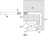
- a touchdown bearing 120 When a touchdown bearing 120 is in the form of a ball bearing the ball of the touchdown bearing 120 may be disposed, at least partially, between the races 123 (as shown in FIG. 4 ).
- the injecting of the working fluid may be completed so as to flush the touchdown bearing 120 to mitigate a buildup of a debris between the ball of the touchdown bearing 120 and the races 123 of the touchdown bearing 120.
- the touchdown bearing 120 may be described to include a front side 121 and a back side 122.
- the working fluid may be injected through a passage 161 in a spacer ring 160 toward the back side 122 of a touchdown bearing 120.
- the passage 161 in the spacer ring 160 may, in certain instances, have a diameter between 0.05 and 0.1 inches (0.13 to 0.25 cm). It will be appreciated that the diameter may be smaller than 0.05 inches (0.13 cm) and greater than 0.1 inches (0.25 cm).
- the passage 161 has an approximately constant diameter across the length of the passage 161.
- the passage 161 has a varying diameter across the length of the passage 161 (e.g., the diameter may be smaller at one end of the passage 161 than the other). It is envisioned that the passage 161 may be provided in any suitable configuration that enables the injection of a working fluid at a sufficient velocity toward a touchdown bearing so as to prevent, or at least mitigate, the buildup of debris around the touchdown bearing 120.
- the spacer ring 160 may be shaped as an annular ring with a recessed portion that extends behind the touchdown bearing(s) 120.
- the supply line 150 may be configured to couple to the passage 161 in the spacer ring 160. Coupling the supply line 150 to the passage 161 in the spacer ring 160 may be interpreted to mean using any suitable mechanism for securing the supply line 150 to the passage 161 in the spacer ring 160 such that a working fluid can be transferred from the supply line 150 through the passage 161 in the spacer ring 160 toward the back side 122 of the touchdown bearing(s) 120.
- the supply line 150 may be configured to couple to the passage 161 in the spacer ring 160 using at least one of: a locking ball mechanism and a threaded connection.
- the locking ball mechanism may extend from an inner surface of either the supply line 150 or the passage 161 in the spacer ring 160.
- the locking balls of the locking ball mechanism may be capable of extending radially inward and outward.
- the inner surface of the supply line 150 may be placed over the outer surface of the passage 161 in the spacer ring 160.
- the outer surface of the supply line 150 may be placed within the inner surface of the passage 161 in the spacer ring 160.
- the locking balls may extend and set into a recess (e.g., in the supply line 150 or the passage 161 in the spacer ring 160) when coupled.
- the locking ball mechanism may incorporate a coupler spring.
- the compressor 100 may provide for the working fluid to be injected from the back side 122 of the touchdown bearing(s) 120 toward the front side 121 of the touchdown bearing(s) 120. Injecting the working fluid from the back side 122 of the touchdown bearing(s) 120 toward the front side 121 of the touchdown bearing(s) 120 may force debris, if any, away from the touchdown bearing(s) 120 (e.g., picking up the debris with the working fluid). In certain instances, the injecting of the working fluid may cause the touchdown bearing(s) 120 to rotate.
- This rotation of the touchdown bearing(s) 120 may help prevent the touchdown bearing(s) 120 from seizing (e.g., from being incapable of rotating and/or resisting rotation).
- debris By injecting the working fluid from the back side 122 of the touchdown bearing(s) 120, debris may be forced away from the electric motor 130. Any debris picked up by the working fluid and forced away from the electric motor 130 may be drained through a drain 131 in the electric motor 130.
- the working fluid may be injected by the supply line 150 at a velocity of at least five (5) ft. /sec (1.5 m/s).
- the velocity may be dependent, at least in part, on the operation of the compressor 100 (e.g., the velocity may increase or decrease as a function of the speed at which the compressor 100 is operated).
- the velocity of the working fluid may also be dependent, at least in part, on the configuration of the passage 161 in the spacer ring 160. It is envisioned that the velocity of the working fluid is sufficiently high enough to prevent, or at least mitigate, the buildup of debris within the touchdown bearing(s) 120.
- the compressor 100 includes at least three touchdown bearings 120 and at least three supply lines 150, where each respective supply line 150 is configured to inject the working fluid toward each respective touchdown bearing 120.
- the compressor 100 may include an independent supply line 150 for each touchdown bearing 120, it is envisioned that the working fluid may be injected toward each touchdown bearing 120 through use of any number of supply lines 150 so long as working fluid is injected toward at least one touchdown bearing 120 in an approximately continuous manner by the supply line(s) 150 when the compressor 100 is operational.
- the compressor 100 may include multiple touchdown bearings 120 and only one supply line 150.
- the compressor 100 may include only one touchdown bearing 120 and multiple supply lines 150.
- the compressor 100 may include only one touchdown bearing 120 and only one supply line 150.
- the design and configuration of the compressor 100 enables the flushing of at least one touchdown bearing 120 within a compressor 100 to prevent, or at least mitigate, the buildup of debris within the respective touchdown bearing(s) 120.
Landscapes
- Engineering & Computer Science (AREA)
- General Engineering & Computer Science (AREA)
- Mechanical Engineering (AREA)
- Physics & Mathematics (AREA)
- Thermal Sciences (AREA)
- Electromagnetism (AREA)
- Fluid Mechanics (AREA)
- Power Engineering (AREA)
- Structures Of Non-Positive Displacement Pumps (AREA)
- Magnetic Bearings And Hydrostatic Bearings (AREA)
- Rolling Contact Bearings (AREA)
Abstract
Description
- The present invention relates to a compressor and to a vapor compression system comprising the compressor.
- Vapor compression systems (e.g., chillers) commonly include a compressor, a condenser, an expansion valve, and an evaporator. Refrigerant circulates through the vapor compression system in order to provide cooling to a medium (e.g., air). The refrigerant exits the compressor through a discharge port at a high pressure and a high enthalpy. The refrigerant then flows through the condenser at a high pressure and rejects heat to an external fluid medium. The refrigerant then flows through the expansion valve, which expands the refrigerant to a low pressure. After expansion, the refrigerant flows through the evaporator and absorbs heat from another medium (e.g., air). The refrigerant then re-enters the compressor through a suction port, completing the cycle.
- Compressors commonly include a motor rotor and a motor stator housed within a compressor housing. The rotor is fixed to and rotates with a rotating shaft, and the stator is fixed inside the compressor housing. Depending on the type of compressor, magnetic bearings may be used to levitate the rotating shaft while the compressor is operational. Touchdown bearings are commonly used by compressors with magnetic bearings to provide for smooth rotation of the shaft and protect the rotor when the compressor is shutdown. The touchdown bearings can be in the form of ball bearings or sleeve bearings. Sleeve bearings are shaped in the form of a sleeve around the rotating shaft, with a clearance between the rotating shaft and the interior facing surface of the sleeve bearing. Commonly, lubricant (e.g., oil) is used to fill the clearance between the sleeve bearing and the rotating shaft. Ball bearings are shaped in the form of a ball and are placed between a pair of races, with a small clearance between the ball and the races. Multiple ball bearings may be placed around the rotating shaft.
- One potential issue with using ball bearings as the touchdown bearings is the potential for debris to deposit within the clearance between the ball and the races. This debris may be in the form of weld particles and/or dust particles within the vapor compression system. If debris builds up within the clearance there is potential that touchdown bearing will seize (e.g., being incapable of rotating and/or resisting rotation), which may result in damage to the rotating shaft.
- Accordingly, there remains a need for a way to flush the touchdown bearings within a compressor to prevent, or at least mitigate, the buildup of debris within the touchdown bearings.
- According to one embodiment, a compressor including an electric motor, a magnetic bearing, a touchdown bearing, and a supply line is provided. The electric motor may be used for driving a rotating shaft. The magnetic bearing may be used for levitating the rotating shaft when the compressor is operational. The magnetic bearing is disposed adjacent to the electric motor. The touchdown bearing is configured to rotate and support the rotating shaft when the compressor is shutdown. The touchdown bearing is disposed adjacent to the rotating shaft. The supply line is in fluid communication with the touchdown bearing. The supply line is configured for injecting a working fluid toward the touchdown bearing. The working fluid is injected approximately continuously by the supply line when the compressor is operational.
- The touchdown bearing may be disposed at least partially between a pair of races.
- The compressor may further include a spacer ring disposed adjacent to the touchdown bearing, wherein the spacer ring includes a passage disposed therein, and the working fluid is injected through the passage toward the touchdown bearing.
- The supply line may be configured to couple to the passage in the spacer ring.
- At least a portion of the working fluid may be drained through a drain in the electric motor.
- Injecting the working fluid may cause the touchdown bearing to rotate between the pair of races.
- Injecting the working fluid mitigates a buildup of a debris between the touchdown bearing and the races.
- The working fluid may be injected at a velocity of at least five (5) ft. /sec (1.5 m/s).
- The passage may have a diameter between 0.05 and 0.1 inches (0.13 to 0.25 cm).
- The injecting of the working fluid may stop when the compressor is shutdown.
- The touchdown bearing may be a ball bearing.
- The compressor may include at least three touchdown bearings and at least three supply lines, each respective supply line may be configured to inject the working fluid toward each respective touchdown bearing.
- The working fluid may be in a substantially liquid phase.
- The working fluid may be R-134A refrigerant.
- The compressor may be a centrifugal compressor.
- The compressor may be an axial compressor.
- The compressor may be a scroll compressor.
- According to another embodiment, a vapor compression system including a condenser and a compressor is provided. The condenser may be used for transferring heat from a working fluid to an external fluid medium. The compressor is in fluid communication with the condenser. The compressor includes an electric motor, a magnetic bearing, a touchdown bearing, and a supply line. The electric motor may be used for driving a rotating shaft. The magnetic bearing may be used for levitating the rotating shaft when the compressor is operational. The magnetic bearing is disposed adjacent to the electric motor. The touchdown bearing is configured to rotate and support the rotating shaft when the compressor is shutdown. The touchdown bearing is disposed adjacent to the rotating shaft. The supply line is in fluid communication with the touchdown bearing and the condenser. The supply line is configured for injecting working fluid from the condenser toward the touchdown bearing. The working fluid is injected approximately continuously by the supply line when the compressor is operational.
- The external fluid medium may include at least one of: an air supply and a water supply.
- The working fluid may be a refrigerant.
- The following descriptions of the drawings and of example embodiments should not be considered limiting, but are provided by way of example only. With reference to the accompanying drawings, like elements are numbered alike:
-
FIG. 1 is a cross-sectional side view of a compressor depicting the injection of a working fluid toward a touchdown bearing. -
FIG. 2 is a schematic illustration of a vapor compression system including a compressor, a condenser, an evaporator, and an expansion valve, with a supply line between the condenser and the compressor. -
FIG. 3 is a cross-sectional view taken along cross-sectional line A-A fromFIG. 1 , depicting multiple touchdown bearings disposed adjacent to a rotating shaft and a spacer ring. -
FIG. 4 is a cross-sectional view taken along cross-sectional line B-B fromFIG. 3 , depicting a touchdown bearing disposed adjacent to a spacer ring. -
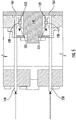
FIG. 5 is an exploded cross-sectional side view of the compressor shown inFIG. 1 depicting the injection of the working fluid toward a back side of the touchdown bearing. - As will be described below, a compressor with a supply line for injecting a working fluid (e.g., a refrigerant) toward the touchdown bearing(s) within the compressor, and a vapor compression system incorporating the same are provided. The touchdown bearing(s) may be in the form of one or more ball bearing(s). The injecting of the working fluid may make it possible to prevent, or at least mitigate, the buildup of debris within the touchdown bearing(s) (e.g., between the ball and the races of the touchdown bearing). In certain instances, the working fluid flushes the touchdown bearing(s) by injecting the working fluid at a sufficient velocity so as to cause debris, if any, within the touchdown bearing(s) to exit the touchdown bearing(s). This flushing of the touchdown bearing(s) with working fluid may help prevent, or at least mitigate, the seizing of the touchdown bearing(s).
- With reference now to the Figures, a cross-sectional side view of a
compressor 100 illustrating the injection of a working fluid toward atouchdown bearing 120 is shown inFIG. 1 . As shown inFIG. 1 , thecompressor 100 includes anelectric motor 130, amagnetic bearing 110, atouchdown bearing 120, and asupply line 150. Theelectric motor 130 is used for driving arotating shaft 140. Themagnetic bearing 110 is used for levitating therotating shaft 140 when thecompressor 100 is operational. Themagnetic bearing 110 is disposed adjacent to theelectric motor 130. Thetouchdown bearing 120 is used for supporting therotating shaft 140 when thecompressor 100 is shutdown. Thetouchdown bearing 120 is disposed adjacent to therotating shaft 140. Thesupply line 150 is used for injecting a working fluid toward thetouchdown bearing 120. Thecompressor 100 provides for the injection of the working fluid approximately continuously by thesupply line 150 when the compressor is operational 100. - As shown in
FIG. 2 , thecompressor 100 may be one component of avapor compression system 800. Thevapor compression system 800 may include acompressor 100, acondenser 200, anexpansion valve 400, and anevaporator 300. In some embodiments, thecompressor 100 is either a centrifugal compressor, an axial compressor, or a scroll compressor. Thevapor compression system 800 may be configured to circulate refrigerant through thevapor compression system 800 to provide cooling to a medium (e.g., air, water, etc.). As shown inFIG. 2 , the working fluid being injected toward the touchdown bearing(s) 120 of thecompressor 100 may be provided from acondenser 200. This working fluid, in certain instances, is refrigerant from thecondenser 200. The working fluid may be in a substantially liquid phase when being injected toward the touchdown bearing(s) 120. A substantially liquid phase can be interpreted to mean that more of the working fluid is in a liquid phase than a vapor phase. In certain instances, thevapor compression system 800 utilizes R-134A as the refrigerant, which is provided as the working fluid being injected toward the touchdown bearing(s) 120 of thecompressor 100. It will be appreciated that other types of refrigerant may be used. - The working fluid may be injected toward the touchdown bearing(s) 120 approximately continuously by the supply line when the
compressor 100 is operational. In certain instances, thecompressor 100 is the driving force for injecting the working fluid toward the touchdown bearing(s) 120. Meaning that when thecompressor 100 is operational thecompressor 100, through generating a positive pressure, forces the working fluid toward the touchdown bearing(s) 120. In certain instances (e.g., when thecompressor 100 is the driving force for injecting the working fluid toward the touchdown bearing(s) 120), the injecting of the working fluid stops when thecompressor 100 is shutdown. This may be because, when thecompressor 100 is shutdown there is no positive pressure being generated that would force the working fluid toward the touchdown bearing(s) 120. Thecompressor 100 may be seen as shutdown when thecompressor 100 is not generating a positive pressure. Thecompressor 100 may be seen as being operational when thecompressor 100 is generating a positive pressure. - As described above, one or more touchdown bearing(s) 120 may be in the form of ball bearing(s). When a
touchdown bearing 120 is in the form of a ball bearing the ball of the touchdown bearing 120 may be disposed, at least partially, between the races 123 (as shown inFIG. 4 ). The injecting of the working fluid may be completed so as to flush the touchdown bearing 120 to mitigate a buildup of a debris between the ball of thetouchdown bearing 120 and theraces 123 of thetouchdown bearing 120. To illustrate the injection of the working fluid toward the touchdown bearing 120, the touchdown bearing 120 may be described to include afront side 121 and aback side 122. - As shown in
FIGs. 3-5 , the working fluid may be injected through apassage 161 in aspacer ring 160 toward theback side 122 of atouchdown bearing 120. Thepassage 161 in thespacer ring 160 may, in certain instances, have a diameter between 0.05 and 0.1 inches (0.13 to 0.25 cm). It will be appreciated that the diameter may be smaller than 0.05 inches (0.13 cm) and greater than 0.1 inches (0.25 cm). In certain instances, thepassage 161 has an approximately constant diameter across the length of thepassage 161. In certain instances, thepassage 161 has a varying diameter across the length of the passage 161 (e.g., the diameter may be smaller at one end of thepassage 161 than the other). It is envisioned that thepassage 161 may be provided in any suitable configuration that enables the injection of a working fluid at a sufficient velocity toward a touchdown bearing so as to prevent, or at least mitigate, the buildup of debris around thetouchdown bearing 120. - The
spacer ring 160 may be shaped as an annular ring with a recessed portion that extends behind the touchdown bearing(s) 120. To transfer the working fluid from thesupply line 150 through thepassage 161 in thespacer ring 160, thesupply line 150 may be configured to couple to thepassage 161 in thespacer ring 160. Coupling thesupply line 150 to thepassage 161 in thespacer ring 160 may be interpreted to mean using any suitable mechanism for securing thesupply line 150 to thepassage 161 in thespacer ring 160 such that a working fluid can be transferred from thesupply line 150 through thepassage 161 in thespacer ring 160 toward theback side 122 of the touchdown bearing(s) 120. - The
supply line 150 may be configured to couple to thepassage 161 in thespacer ring 160 using at least one of: a locking ball mechanism and a threaded connection. The locking ball mechanism may extend from an inner surface of either thesupply line 150 or thepassage 161 in thespacer ring 160. The locking balls of the locking ball mechanism may be capable of extending radially inward and outward. In certain instances, to couple thesupply line 150 to thepassage 161 in thespacer ring 160, the inner surface of thesupply line 150 may be placed over the outer surface of thepassage 161 in thespacer ring 160. In certain instances, to couple thesupply line 150 to thepassage 161 in thespacer ring 160, the outer surface of thesupply line 150 may be placed within the inner surface of thepassage 161 in thespacer ring 160. Regardless of whether the locking balls are incorporated on thesupply line 150 or thepassage 161 in thespacer ring 160, the locking balls may extend and set into a recess (e.g., in thesupply line 150 or thepassage 161 in the spacer ring 160) when coupled. To extend the locking balls in an outward direction toward the recess, the locking ball mechanism may incorporate a coupler spring. - As further shown in
FIG. 4 , when using a threaded connection to couple thesupply line 150 to thepassage 161 in thespacer ring 161, both thesupply line 150 and thepassage 161 in thespacer ring 161 may include threadedportions portion 151 of thesupply line 150 may extend circumferentially around an inner surface or an outer surface of thesupply line 150. The threadedportion 162 of thepassage 161 in thespacer ring 160 may extend circumferentially around an inner surface or an outer surface of thepassage 161 in thespacer ring 160. The threaded connection may allow for thesupply line 150 and thepassage 161 to be coupled to one another by mating the threadedportion 151 of thesupply line 150 to the threadedportion 162 of thepassage 161 in thespacer ring 160. - Regardless of how the
supply line 150 and thepassage 160 in thespacer ring 160 are coupled, thecompressor 100 may provide for the working fluid to be injected from theback side 122 of the touchdown bearing(s) 120 toward thefront side 121 of the touchdown bearing(s) 120. Injecting the working fluid from theback side 122 of the touchdown bearing(s) 120 toward thefront side 121 of the touchdown bearing(s) 120 may force debris, if any, away from the touchdown bearing(s) 120 (e.g., picking up the debris with the working fluid). In certain instances, the injecting of the working fluid may cause the touchdown bearing(s) 120 to rotate. This rotation of the touchdown bearing(s) 120 may help prevent the touchdown bearing(s) 120 from seizing (e.g., from being incapable of rotating and/or resisting rotation). By injecting the working fluid from theback side 122 of the touchdown bearing(s) 120, debris may be forced away from theelectric motor 130. Any debris picked up by the working fluid and forced away from theelectric motor 130 may be drained through adrain 131 in theelectric motor 130. - To effectively flush the touchdown bearing(s) 120 the working fluid may be injected by the
supply line 150 at a velocity of at least five (5) ft. /sec (1.5 m/s). When thecompressor 100 is the driving force for injecting the working fluid, the velocity may be dependent, at least in part, on the operation of the compressor 100 (e.g., the velocity may increase or decrease as a function of the speed at which thecompressor 100 is operated). As described above, the velocity of the working fluid may also be dependent, at least in part, on the configuration of thepassage 161 in thespacer ring 160. It is envisioned that the velocity of the working fluid is sufficiently high enough to prevent, or at least mitigate, the buildup of debris within the touchdown bearing(s) 120. - In certain instances, the
compressor 100 includes at least threetouchdown bearings 120 and at least threesupply lines 150, where eachrespective supply line 150 is configured to inject the working fluid toward eachrespective touchdown bearing 120. Although thecompressor 100 may include anindependent supply line 150 for each touchdown bearing 120, it is envisioned that the working fluid may be injected toward each touchdown bearing 120 through use of any number ofsupply lines 150 so long as working fluid is injected toward at least one touchdown bearing 120 in an approximately continuous manner by the supply line(s) 150 when thecompressor 100 is operational. In certain instances, thecompressor 100 may includemultiple touchdown bearings 120 and only onesupply line 150. In certain instances, thecompressor 100 may include only onetouchdown bearing 120 andmultiple supply lines 150. In certain instances, thecompressor 100 may include only onetouchdown bearing 120 and only onesupply line 150. Regardless of thenumber touchdown bearings 120 and/orsupply lines 150, the design and configuration of thecompressor 100 enables the flushing of at least onetouchdown bearing 120 within acompressor 100 to prevent, or at least mitigate, the buildup of debris within the respective touchdown bearing(s) 120. - While the present disclosure has been described with reference to an exemplary embodiment or embodiments, it will be understood by those skilled in the art that various changes may be made and equivalents may be substituted for elements thereof without departing from the scope of the present invention, as defined by the claims. In addition, many modifications may be made to adapt a particular situation or material to the teachings of the present disclosure. Therefore, it is intended that the present invention not be limited to the particular embodiment disclosed as the best mode contemplated for carrying out this present invention, but that the present invention will include all embodiments falling within the scope of the claims.
Claims (15)
- A compressor (100) comprising:an electric motor (130) for driving a rotating shaft (140);a magnetic bearing (110) for levitating the rotating shaft when the compressor is operational, the magnetic bearing disposed adjacent to the electric motor;a touchdown bearing (120) configured to rotate and support the rotating shaft when the compressor is shutdown, the touchdown bearing disposed adjacent to the rotating shaft; anda supply line (150) in fluid communication with the touchdown bearing, the supply line configured for injecting a working fluid toward the touchdown bearing, wherein the working fluid is injected approximately continuously by the supply line when the compressor is operational.
- The compressor (100) of claim 1, wherein the touchdown bearing (120) is disposed at least partially between a pair of races (123).
- The compressor (100) of claim 1 or 2, further comprising a spacer ring (160) disposed adjacent to the touchdown bearing (120), wherein the spacer ring includes a passage (161) disposed therein, and the working fluid is injected through the passage toward the touchdown bearing, preferably wherein the supply line (150) is configured to couple to the passage in the spacer ring.
- The compressor (100) of claim 1, 2 or 3, wherein at least a portion of the working fluid is drained through a drain (131) in the electric motor (130).
- The compressor (100) of claim 2, wherein injecting the working fluid causes the touchdown bearing (120) to rotate between the pair of races (123), and preferably wherein injecting the working fluid mitigates a buildup of a debris between the touchdown bearing and the races.
- The compressor (100) of any preceding claim, wherein the working fluid is injected at a velocity of at least five (5) ft. /sec (1.5 m/s).
- The compressor (100) of claim 3, wherein the passage (161) comprises a diameter between 0.05 and 0.1 inches (0.13 to 0.25 cm).
- The compressor (100) of any preceding claim, wherein the injecting of the working fluid stops when the compressor is shutdown.
- The compressor (100) of any preceding claim, wherein the touchdown bearing (120) is a ball bearing.
- The compressor (100) of any preceding claim, wherein the compressor comprises at least three touchdown bearings (120) and at least three supply lines (150), each respective supply line configured to inject the working fluid toward each respective touchdown bearing.
- The compressor (100) of any preceding claim, wherein the working fluid is in a substantially liquid phase.
- The compressor (100) of any preceding claim, wherein the working fluid is R-134A refrigerant.
- The compressor (100) of any preceding claim, wherein the compressor is a centrifugal compressor an axial compressor, or a scroll compressor.
- A vapor compression system (800) comprising:a condenser (200) for transferring heat from a working fluid to an external fluid medium; andthe compressor (100) of any preceding claim in fluid communication with the condenser.
- The vapor compression system (800) of claim 14, wherein the external fluid medium is comprised of at least one of: an air supply and a water supply, and preferably wherein the working fluid is a refrigerant.
Applications Claiming Priority (1)
| Application Number | Priority Date | Filing Date | Title |
|---|---|---|---|
| US202062989166P | 2020-03-13 | 2020-03-13 |
Publications (2)
| Publication Number | Publication Date |
|---|---|
| EP3892875A1 true EP3892875A1 (en) | 2021-10-13 |
| EP3892875B1 EP3892875B1 (en) | 2023-08-30 |
Family
ID=74873604
Family Applications (1)
| Application Number | Title | Priority Date | Filing Date |
|---|---|---|---|
| EP21162336.8A Active EP3892875B1 (en) | 2020-03-13 | 2021-03-12 | Flushing of a touchdown bearing |
Country Status (4)
| Country | Link |
|---|---|
| US (1) | US11846296B2 (en) |
| EP (1) | EP3892875B1 (en) |
| CN (1) | CN113389752A (en) |
| ES (1) | ES2954846T3 (en) |
Families Citing this family (2)
| Publication number | Priority date | Publication date | Assignee | Title |
|---|---|---|---|---|
| WO2019207681A1 (en) * | 2018-04-25 | 2019-10-31 | 株式会社小松製作所 | Work machine for motor grader |
| US11371208B2 (en) * | 2018-04-25 | 2022-06-28 | Komatsu Ltd. | Work equipment for motor grader |
Citations (3)
| Publication number | Priority date | Publication date | Assignee | Title |
|---|---|---|---|---|
| FR2893684A1 (en) * | 2005-11-24 | 2007-05-25 | Mecanique Magnetique Sa Soc D | EMERGENCY BEARING ARRANGEMENT FOR ROTATING MACHINE WITH ACTIVE MAGNETIC BEARINGS |
| WO2014158329A1 (en) * | 2013-03-25 | 2014-10-02 | Carrier Corporation | Compressor bearing cooling |
| US20190211834A1 (en) * | 2016-04-22 | 2019-07-11 | Mitsubishi Heavy Industries Thermal Systems, Ltd. | Turbo compressor and turbo refrigerator provided with same |
Family Cites Families (4)
| Publication number | Priority date | Publication date | Assignee | Title |
|---|---|---|---|---|
| WO2007023684A1 (en) * | 2005-08-22 | 2007-03-01 | Ntn Corporation | Air cycle refrigerating/cooling system and turbine unit used therefor |
| US8104298B2 (en) * | 2005-12-06 | 2012-01-31 | Carrier Corporation | Lubrication system for touchdown bearings of a magnetic bearing compressor |
| CN200958484Y (en) * | 2006-08-15 | 2007-10-10 | 力致科技股份有限公司 | Improvement of Magnetic Suction Bearing Structure of Cooling Fan |
| US20190203730A1 (en) * | 2017-12-29 | 2019-07-04 | Johnson Controls Technology Company | Thrust bearing placement for compressor |
-
2021
- 2021-02-26 US US17/249,298 patent/US11846296B2/en active Active
- 2021-03-12 EP EP21162336.8A patent/EP3892875B1/en active Active
- 2021-03-12 ES ES21162336T patent/ES2954846T3/en active Active
- 2021-03-12 CN CN202110270502.6A patent/CN113389752A/en active Pending
Patent Citations (3)
| Publication number | Priority date | Publication date | Assignee | Title |
|---|---|---|---|---|
| FR2893684A1 (en) * | 2005-11-24 | 2007-05-25 | Mecanique Magnetique Sa Soc D | EMERGENCY BEARING ARRANGEMENT FOR ROTATING MACHINE WITH ACTIVE MAGNETIC BEARINGS |
| WO2014158329A1 (en) * | 2013-03-25 | 2014-10-02 | Carrier Corporation | Compressor bearing cooling |
| US20190211834A1 (en) * | 2016-04-22 | 2019-07-11 | Mitsubishi Heavy Industries Thermal Systems, Ltd. | Turbo compressor and turbo refrigerator provided with same |
Also Published As
| Publication number | Publication date |
|---|---|
| EP3892875B1 (en) | 2023-08-30 |
| US11846296B2 (en) | 2023-12-19 |
| CN113389752A (en) | 2021-09-14 |
| US20210285453A1 (en) | 2021-09-16 |
| ES2954846T3 (en) | 2023-11-27 |
Similar Documents
| Publication | Publication Date | Title |
|---|---|---|
| EP1963762B1 (en) | Lubrication system for touchdown bearings of a magnetic bearing compressor | |
| US11306726B2 (en) | Foil bearing assembly and compressor including same | |
| EP2409920B1 (en) | Centrifugal compressor cooling path arrangement | |
| US11892031B2 (en) | Bearing for supporting a rotating compressor shaft | |
| EP3450701B1 (en) | Turbomachine systems with magnetic bearing | |
| EP3892875B1 (en) | Flushing of a touchdown bearing | |
| EP2893617B1 (en) | Motor rotor and air gap cooling | |
| CN101504009A (en) | Turbo compressor and refrigerator | |
| CN111365258A (en) | Compressor and air conditioning unit | |
| EP3775559B1 (en) | Screw compressor element and machine | |
| CN103608550A (en) | Waste heat power generator | |
| US10107298B2 (en) | Turbo machine | |
| US20250361872A1 (en) | Sealing system for magnetic levitating centrifugal compressor and magnetic levitating centrifugal compressor | |
| EP4212735A1 (en) | Sealing system for a magnetic levitating centrifugal compressor and a magnetic levitating centrifugal compressor | |
| EP0806571B1 (en) | A rotatable assembly for supporting the rotor of a vacuum pump | |
| US5833374A (en) | Rotatable assembly for supporting of the rotor of a vacuum pump | |
| JP7381976B2 (en) | Thrust magnetic bearing rotors, thrust magnetic bearings, and rotary fluid machines | |
| WO2020134504A1 (en) | Motor rotor, compressor, and air conditioner | |
| JP2024071328A (en) | Vacuum pump with improved suction capacity of Holweck pump stage | |
| JP2018115671A (en) | Rotary machine and lubrication system of rotary machine | |
| CN116066381A (en) | Magnetic levitation centrifugal compressor, refrigeration system and refrigeration equipment having same | |
| HK1127514B (en) | Lubrication system for touchdown bearings of a magnetic bearing compressor |
Legal Events
| Date | Code | Title | Description |
|---|---|---|---|
| PUAI | Public reference made under article 153(3) epc to a published international application that has entered the european phase |
Free format text: ORIGINAL CODE: 0009012 |
|
| STAA | Information on the status of an ep patent application or granted ep patent |
Free format text: STATUS: THE APPLICATION HAS BEEN PUBLISHED |
|
| AK | Designated contracting states |
Kind code of ref document: A1 Designated state(s): AL AT BE BG CH CY CZ DE DK EE ES FI FR GB GR HR HU IE IS IT LI LT LU LV MC MK MT NL NO PL PT RO RS SE SI SK SM TR |
|
| STAA | Information on the status of an ep patent application or granted ep patent |
Free format text: STATUS: REQUEST FOR EXAMINATION WAS MADE |
|
| 17P | Request for examination filed |
Effective date: 20220325 |
|
| RBV | Designated contracting states (corrected) |
Designated state(s): AL AT BE BG CH CY CZ DE DK EE ES FI FR GB GR HR HU IE IS IT LI LT LU LV MC MK MT NL NO PL PT RO RS SE SI SK SM TR |
|
| STAA | Information on the status of an ep patent application or granted ep patent |
Free format text: STATUS: EXAMINATION IS IN PROGRESS |
|
| 17Q | First examination report despatched |
Effective date: 20220803 |
|
| REG | Reference to a national code |
Ref country code: DE Ref legal event code: R079 Free format text: PREVIOUS MAIN CLASS: F16C0019520000 Ipc: F16C0033660000 Ref country code: DE Ref legal event code: R079 Ref document number: 602021004594 Country of ref document: DE Free format text: PREVIOUS MAIN CLASS: F16C0019520000 Ipc: F16C0033660000 |
|
| GRAP | Despatch of communication of intention to grant a patent |
Free format text: ORIGINAL CODE: EPIDOSNIGR1 |
|
| STAA | Information on the status of an ep patent application or granted ep patent |
Free format text: STATUS: GRANT OF PATENT IS INTENDED |
|
| RIC1 | Information provided on ipc code assigned before grant |
Ipc: F16C 32/04 20060101ALI20230302BHEP Ipc: F16C 39/02 20060101ALI20230302BHEP Ipc: F16C 33/66 20060101AFI20230302BHEP |
|
| INTG | Intention to grant announced |
Effective date: 20230317 |
|
| GRAS | Grant fee paid |
Free format text: ORIGINAL CODE: EPIDOSNIGR3 |
|
| GRAA | (expected) grant |
Free format text: ORIGINAL CODE: 0009210 |
|
| STAA | Information on the status of an ep patent application or granted ep patent |
Free format text: STATUS: THE PATENT HAS BEEN GRANTED |
|
| AK | Designated contracting states |
Kind code of ref document: B1 Designated state(s): AL AT BE BG CH CY CZ DE DK EE ES FI FR GB GR HR HU IE IS IT LI LT LU LV MC MK MT NL NO PL PT RO RS SE SI SK SM TR |
|
| REG | Reference to a national code |
Ref country code: GB Ref legal event code: FG4D |
|
| REG | Reference to a national code |
Ref country code: CH Ref legal event code: EP |
|
| REG | Reference to a national code |
Ref country code: DE Ref legal event code: R096 Ref document number: 602021004594 Country of ref document: DE |
|
| REG | Reference to a national code |
Ref country code: IE Ref legal event code: FG4D |
|
| REG | Reference to a national code |
Ref country code: ES Ref legal event code: FG2A Ref document number: 2954846 Country of ref document: ES Kind code of ref document: T3 Effective date: 20231127 |
|
| REG | Reference to a national code |
Ref country code: LT Ref legal event code: MG9D |
|
| REG | Reference to a national code |
Ref country code: NL Ref legal event code: MP Effective date: 20230830 |
|
| REG | Reference to a national code |
Ref country code: AT Ref legal event code: MK05 Ref document number: 1605803 Country of ref document: AT Kind code of ref document: T Effective date: 20230830 |
|
| PG25 | Lapsed in a contracting state [announced via postgrant information from national office to epo] |
Ref country code: GR Free format text: LAPSE BECAUSE OF FAILURE TO SUBMIT A TRANSLATION OF THE DESCRIPTION OR TO PAY THE FEE WITHIN THE PRESCRIBED TIME-LIMIT Effective date: 20231201 |
|
| PG25 | Lapsed in a contracting state [announced via postgrant information from national office to epo] |
Ref country code: IS Free format text: LAPSE BECAUSE OF FAILURE TO SUBMIT A TRANSLATION OF THE DESCRIPTION OR TO PAY THE FEE WITHIN THE PRESCRIBED TIME-LIMIT Effective date: 20231230 |
|
| PG25 | Lapsed in a contracting state [announced via postgrant information from national office to epo] |
Ref country code: SE Free format text: LAPSE BECAUSE OF FAILURE TO SUBMIT A TRANSLATION OF THE DESCRIPTION OR TO PAY THE FEE WITHIN THE PRESCRIBED TIME-LIMIT Effective date: 20230830 Ref country code: RS Free format text: LAPSE BECAUSE OF FAILURE TO SUBMIT A TRANSLATION OF THE DESCRIPTION OR TO PAY THE FEE WITHIN THE PRESCRIBED TIME-LIMIT Effective date: 20230830 Ref country code: NO Free format text: LAPSE BECAUSE OF FAILURE TO SUBMIT A TRANSLATION OF THE DESCRIPTION OR TO PAY THE FEE WITHIN THE PRESCRIBED TIME-LIMIT Effective date: 20231130 Ref country code: LV Free format text: LAPSE BECAUSE OF FAILURE TO SUBMIT A TRANSLATION OF THE DESCRIPTION OR TO PAY THE FEE WITHIN THE PRESCRIBED TIME-LIMIT Effective date: 20230830 Ref country code: LT Free format text: LAPSE BECAUSE OF FAILURE TO SUBMIT A TRANSLATION OF THE DESCRIPTION OR TO PAY THE FEE WITHIN THE PRESCRIBED TIME-LIMIT Effective date: 20230830 Ref country code: IS Free format text: LAPSE BECAUSE OF FAILURE TO SUBMIT A TRANSLATION OF THE DESCRIPTION OR TO PAY THE FEE WITHIN THE PRESCRIBED TIME-LIMIT Effective date: 20231230 Ref country code: HR Free format text: LAPSE BECAUSE OF FAILURE TO SUBMIT A TRANSLATION OF THE DESCRIPTION OR TO PAY THE FEE WITHIN THE PRESCRIBED TIME-LIMIT Effective date: 20230830 Ref country code: GR Free format text: LAPSE BECAUSE OF FAILURE TO SUBMIT A TRANSLATION OF THE DESCRIPTION OR TO PAY THE FEE WITHIN THE PRESCRIBED TIME-LIMIT Effective date: 20231201 Ref country code: FI Free format text: LAPSE BECAUSE OF FAILURE TO SUBMIT A TRANSLATION OF THE DESCRIPTION OR TO PAY THE FEE WITHIN THE PRESCRIBED TIME-LIMIT Effective date: 20230830 Ref country code: AT Free format text: LAPSE BECAUSE OF FAILURE TO SUBMIT A TRANSLATION OF THE DESCRIPTION OR TO PAY THE FEE WITHIN THE PRESCRIBED TIME-LIMIT Effective date: 20230830 |
|
| P01 | Opt-out of the competence of the unified patent court (upc) registered |
Effective date: 20240119 |
|
| PG25 | Lapsed in a contracting state [announced via postgrant information from national office to epo] |
Ref country code: PL Free format text: LAPSE BECAUSE OF FAILURE TO SUBMIT A TRANSLATION OF THE DESCRIPTION OR TO PAY THE FEE WITHIN THE PRESCRIBED TIME-LIMIT Effective date: 20230830 Ref country code: NL Free format text: LAPSE BECAUSE OF FAILURE TO SUBMIT A TRANSLATION OF THE DESCRIPTION OR TO PAY THE FEE WITHIN THE PRESCRIBED TIME-LIMIT Effective date: 20230830 |
|
| PG25 | Lapsed in a contracting state [announced via postgrant information from national office to epo] |
Ref country code: SM Free format text: LAPSE BECAUSE OF FAILURE TO SUBMIT A TRANSLATION OF THE DESCRIPTION OR TO PAY THE FEE WITHIN THE PRESCRIBED TIME-LIMIT Effective date: 20230830 Ref country code: RO Free format text: LAPSE BECAUSE OF FAILURE TO SUBMIT A TRANSLATION OF THE DESCRIPTION OR TO PAY THE FEE WITHIN THE PRESCRIBED TIME-LIMIT Effective date: 20230830 Ref country code: EE Free format text: LAPSE BECAUSE OF FAILURE TO SUBMIT A TRANSLATION OF THE DESCRIPTION OR TO PAY THE FEE WITHIN THE PRESCRIBED TIME-LIMIT Effective date: 20230830 Ref country code: DK Free format text: LAPSE BECAUSE OF FAILURE TO SUBMIT A TRANSLATION OF THE DESCRIPTION OR TO PAY THE FEE WITHIN THE PRESCRIBED TIME-LIMIT Effective date: 20230830 Ref country code: CZ Free format text: LAPSE BECAUSE OF FAILURE TO SUBMIT A TRANSLATION OF THE DESCRIPTION OR TO PAY THE FEE WITHIN THE PRESCRIBED TIME-LIMIT Effective date: 20230830 Ref country code: PT Free format text: LAPSE BECAUSE OF FAILURE TO SUBMIT A TRANSLATION OF THE DESCRIPTION OR TO PAY THE FEE WITHIN THE PRESCRIBED TIME-LIMIT Effective date: 20240102 Ref country code: SK Free format text: LAPSE BECAUSE OF FAILURE TO SUBMIT A TRANSLATION OF THE DESCRIPTION OR TO PAY THE FEE WITHIN THE PRESCRIBED TIME-LIMIT Effective date: 20230830 |
|
| PGFP | Annual fee paid to national office [announced via postgrant information from national office to epo] |
Ref country code: BE Payment date: 20240220 Year of fee payment: 4 |
|
| REG | Reference to a national code |
Ref country code: DE Ref legal event code: R097 Ref document number: 602021004594 Country of ref document: DE |
|
| PLBE | No opposition filed within time limit |
Free format text: ORIGINAL CODE: 0009261 |
|
| STAA | Information on the status of an ep patent application or granted ep patent |
Free format text: STATUS: NO OPPOSITION FILED WITHIN TIME LIMIT |
|
| PG25 | Lapsed in a contracting state [announced via postgrant information from national office to epo] |
Ref country code: SI Free format text: LAPSE BECAUSE OF FAILURE TO SUBMIT A TRANSLATION OF THE DESCRIPTION OR TO PAY THE FEE WITHIN THE PRESCRIBED TIME-LIMIT Effective date: 20230830 |
|
| 26N | No opposition filed |
Effective date: 20240603 |
|
| REG | Reference to a national code |
Ref country code: CH Ref legal event code: PL |
|
| PG25 | Lapsed in a contracting state [announced via postgrant information from national office to epo] |
Ref country code: BG Free format text: LAPSE BECAUSE OF FAILURE TO SUBMIT A TRANSLATION OF THE DESCRIPTION OR TO PAY THE FEE WITHIN THE PRESCRIBED TIME-LIMIT Effective date: 20230830 |
|
| PG25 | Lapsed in a contracting state [announced via postgrant information from national office to epo] |
Ref country code: LU Free format text: LAPSE BECAUSE OF NON-PAYMENT OF DUE FEES Effective date: 20240312 |
|
| PG25 | Lapsed in a contracting state [announced via postgrant information from national office to epo] |
Ref country code: MC Free format text: LAPSE BECAUSE OF FAILURE TO SUBMIT A TRANSLATION OF THE DESCRIPTION OR TO PAY THE FEE WITHIN THE PRESCRIBED TIME-LIMIT Effective date: 20230830 |
|
| PG25 | Lapsed in a contracting state [announced via postgrant information from national office to epo] |
Ref country code: MC Free format text: LAPSE BECAUSE OF FAILURE TO SUBMIT A TRANSLATION OF THE DESCRIPTION OR TO PAY THE FEE WITHIN THE PRESCRIBED TIME-LIMIT Effective date: 20230830 Ref country code: LU Free format text: LAPSE BECAUSE OF NON-PAYMENT OF DUE FEES Effective date: 20240312 Ref country code: BG Free format text: LAPSE BECAUSE OF FAILURE TO SUBMIT A TRANSLATION OF THE DESCRIPTION OR TO PAY THE FEE WITHIN THE PRESCRIBED TIME-LIMIT Effective date: 20230830 |
|
| PG25 | Lapsed in a contracting state [announced via postgrant information from national office to epo] |
Ref country code: IE Free format text: LAPSE BECAUSE OF NON-PAYMENT OF DUE FEES Effective date: 20240312 |
|
| PG25 | Lapsed in a contracting state [announced via postgrant information from national office to epo] |
Ref country code: IE Free format text: LAPSE BECAUSE OF NON-PAYMENT OF DUE FEES Effective date: 20240312 Ref country code: CH Free format text: LAPSE BECAUSE OF NON-PAYMENT OF DUE FEES Effective date: 20240331 |
|
| PGFP | Annual fee paid to national office [announced via postgrant information from national office to epo] |
Ref country code: IT Payment date: 20250218 Year of fee payment: 5 |
|
| PGFP | Annual fee paid to national office [announced via postgrant information from national office to epo] |
Ref country code: ES Payment date: 20250401 Year of fee payment: 5 |
|
| PG25 | Lapsed in a contracting state [announced via postgrant information from national office to epo] |
Ref country code: CY Free format text: LAPSE BECAUSE OF FAILURE TO SUBMIT A TRANSLATION OF THE DESCRIPTION OR TO PAY THE FEE WITHIN THE PRESCRIBED TIME-LIMIT; INVALID AB INITIO Effective date: 20210312 |
|
| PG25 | Lapsed in a contracting state [announced via postgrant information from national office to epo] |
Ref country code: HU Free format text: LAPSE BECAUSE OF FAILURE TO SUBMIT A TRANSLATION OF THE DESCRIPTION OR TO PAY THE FEE WITHIN THE PRESCRIBED TIME-LIMIT; INVALID AB INITIO Effective date: 20210312 |
|
| GBPC | Gb: european patent ceased through non-payment of renewal fee |
Effective date: 20250312 |
|
| PG25 | Lapsed in a contracting state [announced via postgrant information from national office to epo] |
Ref country code: TR Free format text: LAPSE BECAUSE OF FAILURE TO SUBMIT A TRANSLATION OF THE DESCRIPTION OR TO PAY THE FEE WITHIN THE PRESCRIBED TIME-LIMIT Effective date: 20230830 |
|
| REG | Reference to a national code |
Ref country code: BE Ref legal event code: MM Effective date: 20250331 |
|
| PG25 | Lapsed in a contracting state [announced via postgrant information from national office to epo] |
Ref country code: GB Free format text: LAPSE BECAUSE OF NON-PAYMENT OF DUE FEES Effective date: 20250312 |
|
| PG25 | Lapsed in a contracting state [announced via postgrant information from national office to epo] |
Ref country code: BE Free format text: LAPSE BECAUSE OF NON-PAYMENT OF DUE FEES Effective date: 20250331 |
|
| PGFP | Annual fee paid to national office [announced via postgrant information from national office to epo] |
Ref country code: DE Payment date: 20260219 Year of fee payment: 6 |
|
| PGFP | Annual fee paid to national office [announced via postgrant information from national office to epo] |
Ref country code: FR Payment date: 20260219 Year of fee payment: 6 |