EP3892858A2 - Pump system - Google Patents
Pump system Download PDFInfo
- Publication number
- EP3892858A2 EP3892858A2 EP21167221.7A EP21167221A EP3892858A2 EP 3892858 A2 EP3892858 A2 EP 3892858A2 EP 21167221 A EP21167221 A EP 21167221A EP 3892858 A2 EP3892858 A2 EP 3892858A2
- Authority
- EP
- European Patent Office
- Prior art keywords
- pump
- flow rate
- pump system
- fluid
- control unit
- Prior art date
- Legal status (The legal status is an assumption and is not a legal conclusion. Google has not performed a legal analysis and makes no representation as to the accuracy of the status listed.)
- Withdrawn
Links
- 239000012530 fluid Substances 0.000 claims abstract description 51
- 239000010409 thin film Substances 0.000 claims description 4
- 239000000463 material Substances 0.000 claims description 2
- 230000003247 decreasing effect Effects 0.000 claims 2
- 238000005259 measurement Methods 0.000 description 22
- 238000000034 method Methods 0.000 description 10
- 230000010354 integration Effects 0.000 description 5
- 238000010586 diagram Methods 0.000 description 2
- 238000011156 evaluation Methods 0.000 description 2
- NOESYZHRGYRDHS-UHFFFAOYSA-N insulin Chemical compound N1C(=O)C(NC(=O)C(CCC(N)=O)NC(=O)C(CCC(O)=O)NC(=O)C(C(C)C)NC(=O)C(NC(=O)CN)C(C)CC)CSSCC(C(NC(CO)C(=O)NC(CC(C)C)C(=O)NC(CC=2C=CC(O)=CC=2)C(=O)NC(CCC(N)=O)C(=O)NC(CC(C)C)C(=O)NC(CCC(O)=O)C(=O)NC(CC(N)=O)C(=O)NC(CC=2C=CC(O)=CC=2)C(=O)NC(CSSCC(NC(=O)C(C(C)C)NC(=O)C(CC(C)C)NC(=O)C(CC=2C=CC(O)=CC=2)NC(=O)C(CC(C)C)NC(=O)C(C)NC(=O)C(CCC(O)=O)NC(=O)C(C(C)C)NC(=O)C(CC(C)C)NC(=O)C(CC=2NC=NC=2)NC(=O)C(CO)NC(=O)CNC2=O)C(=O)NCC(=O)NC(CCC(O)=O)C(=O)NC(CCCNC(N)=N)C(=O)NCC(=O)NC(CC=3C=CC=CC=3)C(=O)NC(CC=3C=CC=CC=3)C(=O)NC(CC=3C=CC(O)=CC=3)C(=O)NC(C(C)O)C(=O)N3C(CCC3)C(=O)NC(CCCCN)C(=O)NC(C)C(O)=O)C(=O)NC(CC(N)=O)C(O)=O)=O)NC(=O)C(C(C)CC)NC(=O)C(CO)NC(=O)C(C(C)O)NC(=O)C1CSSCC2NC(=O)C(CC(C)C)NC(=O)C(NC(=O)C(CCC(N)=O)NC(=O)C(CC(N)=O)NC(=O)C(NC(=O)C(N)CC=1C=CC=CC=1)C(C)C)CC1=CN=CN1 NOESYZHRGYRDHS-UHFFFAOYSA-N 0.000 description 2
- 238000012986 modification Methods 0.000 description 2
- 230000004048 modification Effects 0.000 description 2
- 238000012935 Averaging Methods 0.000 description 1
- 102000004877 Insulin Human genes 0.000 description 1
- 108090001061 Insulin Proteins 0.000 description 1
- 238000004891 communication Methods 0.000 description 1
- 230000007423 decrease Effects 0.000 description 1
- 230000001419 dependent effect Effects 0.000 description 1
- 229940125396 insulin Drugs 0.000 description 1
- 239000007788 liquid Substances 0.000 description 1
- 238000012545 processing Methods 0.000 description 1
- 230000001131 transforming effect Effects 0.000 description 1
- 238000011144 upstream manufacturing Methods 0.000 description 1
Images

Classifications
-
- F—MECHANICAL ENGINEERING; LIGHTING; HEATING; WEAPONS; BLASTING
- F04—POSITIVE - DISPLACEMENT MACHINES FOR LIQUIDS; PUMPS FOR LIQUIDS OR ELASTIC FLUIDS
- F04B—POSITIVE-DISPLACEMENT MACHINES FOR LIQUIDS; PUMPS
- F04B43/00—Machines, pumps, or pumping installations having flexible working members
- F04B43/02—Machines, pumps, or pumping installations having flexible working members having plate-like flexible members, e.g. diaphragms
- F04B43/04—Pumps having electric drive
- F04B43/043—Micropumps
- F04B43/046—Micropumps with piezoelectric drive
-
- A—HUMAN NECESSITIES
- A61—MEDICAL OR VETERINARY SCIENCE; HYGIENE
- A61M—DEVICES FOR INTRODUCING MEDIA INTO, OR ONTO, THE BODY; DEVICES FOR TRANSDUCING BODY MEDIA OR FOR TAKING MEDIA FROM THE BODY; DEVICES FOR PRODUCING OR ENDING SLEEP OR STUPOR
- A61M5/00—Devices for bringing media into the body in a subcutaneous, intra-vascular or intramuscular way; Accessories therefor, e.g. filling or cleaning devices, arm-rests
- A61M5/14—Infusion devices, e.g. infusing by gravity; Blood infusion; Accessories therefor
- A61M5/142—Pressure infusion, e.g. using pumps
-
- A—HUMAN NECESSITIES
- A61—MEDICAL OR VETERINARY SCIENCE; HYGIENE
- A61M—DEVICES FOR INTRODUCING MEDIA INTO, OR ONTO, THE BODY; DEVICES FOR TRANSDUCING BODY MEDIA OR FOR TAKING MEDIA FROM THE BODY; DEVICES FOR PRODUCING OR ENDING SLEEP OR STUPOR
- A61M5/00—Devices for bringing media into the body in a subcutaneous, intra-vascular or intramuscular way; Accessories therefor, e.g. filling or cleaning devices, arm-rests
- A61M5/14—Infusion devices, e.g. infusing by gravity; Blood infusion; Accessories therefor
- A61M5/168—Means for controlling media flow to the body or for metering media to the body, e.g. drip meters, counters ; Monitoring media flow to the body
- A61M5/16886—Means for controlling media flow to the body or for metering media to the body, e.g. drip meters, counters ; Monitoring media flow to the body for measuring fluid flow rate, i.e. flowmeters
-
- F—MECHANICAL ENGINEERING; LIGHTING; HEATING; WEAPONS; BLASTING
- F04—POSITIVE - DISPLACEMENT MACHINES FOR LIQUIDS; PUMPS FOR LIQUIDS OR ELASTIC FLUIDS
- F04B—POSITIVE-DISPLACEMENT MACHINES FOR LIQUIDS; PUMPS
- F04B43/00—Machines, pumps, or pumping installations having flexible working members
- F04B43/02—Machines, pumps, or pumping installations having flexible working members having plate-like flexible members, e.g. diaphragms
- F04B43/028—Machines, pumps, or pumping installations having flexible working members having plate-like flexible members, e.g. diaphragms with in- or outlet valve arranged in the plate-like flexible member
-
- F—MECHANICAL ENGINEERING; LIGHTING; HEATING; WEAPONS; BLASTING
- F04—POSITIVE - DISPLACEMENT MACHINES FOR LIQUIDS; PUMPS FOR LIQUIDS OR ELASTIC FLUIDS
- F04B—POSITIVE-DISPLACEMENT MACHINES FOR LIQUIDS; PUMPS
- F04B49/00—Control, e.g. of pump delivery, or pump pressure of, or safety measures for, machines, pumps, or pumping installations, not otherwise provided for, or of interest apart from, groups F04B1/00 - F04B47/00
- F04B49/02—Stopping, starting, unloading or idling control
-
- F—MECHANICAL ENGINEERING; LIGHTING; HEATING; WEAPONS; BLASTING
- F04—POSITIVE - DISPLACEMENT MACHINES FOR LIQUIDS; PUMPS FOR LIQUIDS OR ELASTIC FLUIDS
- F04B—POSITIVE-DISPLACEMENT MACHINES FOR LIQUIDS; PUMPS
- F04B49/00—Control, e.g. of pump delivery, or pump pressure of, or safety measures for, machines, pumps, or pumping installations, not otherwise provided for, or of interest apart from, groups F04B1/00 - F04B47/00
- F04B49/06—Control using electricity
- F04B49/065—Control using electricity and making use of computers
-
- A—HUMAN NECESSITIES
- A61—MEDICAL OR VETERINARY SCIENCE; HYGIENE
- A61M—DEVICES FOR INTRODUCING MEDIA INTO, OR ONTO, THE BODY; DEVICES FOR TRANSDUCING BODY MEDIA OR FOR TAKING MEDIA FROM THE BODY; DEVICES FOR PRODUCING OR ENDING SLEEP OR STUPOR
- A61M5/00—Devices for bringing media into the body in a subcutaneous, intra-vascular or intramuscular way; Accessories therefor, e.g. filling or cleaning devices, arm-rests
- A61M5/14—Infusion devices, e.g. infusing by gravity; Blood infusion; Accessories therefor
- A61M5/142—Pressure infusion, e.g. using pumps
- A61M2005/14208—Pressure infusion, e.g. using pumps with a programmable infusion control system, characterised by the infusion program
-
- F—MECHANICAL ENGINEERING; LIGHTING; HEATING; WEAPONS; BLASTING
- F04—POSITIVE - DISPLACEMENT MACHINES FOR LIQUIDS; PUMPS FOR LIQUIDS OR ELASTIC FLUIDS
- F04B—POSITIVE-DISPLACEMENT MACHINES FOR LIQUIDS; PUMPS
- F04B2205/00—Fluid parameters
- F04B2205/09—Flow through the pump
Definitions
- the disclosure relates to a pump system.
- Patent Literature 1 JP 2011-160868A discloses a pump using a MEMS (micro electro mechanical systems) technique.
- the flow rate of a fluid sent by the pump is measured by a flow rate sensor, on/off control of the pump is performed through feedback control that performs feedback of the flow rate measured by the flow rate sensor, and thus the pump is controlled such that a target flow rate is achieved.
- control is often performed in which the ejection amount of fluid ejected by a current point in time and the ejection amount of fluid that is to be ejected by the current point in time are compared, and, if the former is smaller than the latter, the pump is turned on, or otherwise the pump is turned off.
- the former ejection amount can be calculated from the measured flow rate, and the latter ejection amount can be set from the target flow rate.
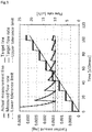
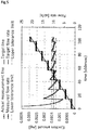
- FIG. 1 shows an example of a graph showing a relationship between the measured flow rate of the fluid and the actual integral ejection amount of the fluid based thereon (which can be calculated as an integral value of the measured flow rate) and the time, in the case in which the above-described control is performed.
- FIG. 1 shows a graph of the measured flow rate of the fluid and a graph of the actual integral ejection amount of the fluid based thereon (hereinafter, referred to as an "actual measurement line”), and also shows a line indicating the integral ejection amount of the fluid that is to be ejected according to the target flow rate (hereinafter, referred to as a "target line").
- the target flow rate is indicated by the dotted line
- lines indicating the upper and lower flow rate tolerance limits based on the target flow rate are respectively indicated by a dash-dotted line and a dash-double-dotted line.
- the target line is not at the center of the actual measurement line, and the actual measurement line is biased upward relative to the target line. Furthermore, the measured flow rate may be frequently higher than the upper tolerance limit. As a result, in the above-described control, the trumpet curve deteriorates.
- the trumpet curve is one of evaluation items regarding the pump performance as defined in JIS (Japanese Industrial Standards) T 0601-2-24:2018, and is obtained by plotting a maximum value of errors on the upper side and a minimum value of errors on the lower side of average measured flow rates of a plurality of measurement time periods (which are respectively referred to as a "maximum measurement error (Ep(max))” and a “minimum measurement error (Ep(min))”) relative to the average measured flow rate over the entire measurement section, as well as a difference between the target flow rate and the average measured flow rate over the entire measurement section.
- JIS Japanese Industrial Standards
- the trumpet curve is a curve indicating the level of precision of an ejection amount of a pump with respect to a target value and the variability of a flow rate.
- a pump system is a pump system including: a pump configured to intermittently perform an ejecting operation that ejects a fluid; a flow meter configured to measure a flow rate of the fluid ejected from the pump; and a control unit connected to the pump and the flow meter, configured to decide on a length of a stopping section during which the ejecting operation is stopped such that an ejection amount of fluid excessively ejected from the pump is canceled, based on a measured flow rate, which is the flow rate measured by the flow meter, and a target flow rate of the pump set in advance, and configured to control the pump so as to stop the ejecting operation according to the length of the stopping section.
- a pump system is the pump system according to the first aspect, wherein the control unit determines whether or not to stop the ejecting operation, by comparing an ejection amount of fluid ejected from the pump based on the measured flow rate and an ejection amount of fluid that is to be ejected from the pump based on the target flow rate, and decides on the length of the stopping section in a case of stopping the ejecting operation.
- a pump system is the pump system according to the second aspect, wherein it is determined to stop the ejecting operation in a case in which the ejection amount based on the measured flow rate is larger than the ejection amount based on the target flow rate.
- a length of a stopping section during which the ejecting operation of a pump is stopped is decided on such that an ejection amount of fluid excessively ejected from the pump is canceled, based on a measured flow rate measured by a flow meter and a target flow rate of the pump set in advance. Then, the pump is controlled such that the ejecting operation of the pump is stopped according to the decided length of the stopping section. Accordingly, the target line of the flow rate becomes closer to the center of the actual measurement line, and the actual measurement line is prevented from being excessively biased upward relative to the target line. As a result, the trumpet curve of the pump system is improved.
- FIG. 2 shows a configuration diagram of a pump system 100 according to this embodiment.
- the pump system 100 includes a tank 1 configured to store a fluid, and a pump 2 arranged downstream of the tank 1 and configured to suck and eject the fluid in the tank 1.
- the upstream and the downstream are defined according to the flow of a fluid.
- the pump 2 intermittently performs an ejecting operation that ejects the fluid.
- the pump system 100 further includes a flow meter 3 configured to measure the flow rate of the fluid ejected from the pump 2, and a control unit 4 connected to the pump 2 and the flow meter 3.
- the control unit 4 controls the fluid transporting operation that is performed by the pump system 100. At this time, the control unit 4 performs feedback control that controls the ejecting operation of the pump 2, based on a measured value Mfr of the flow rate measured by the flow meter 3.
- the pump 2 of this embodiment is, but is not limited to, a small or ultra-small pump that enables a fluid to flow at a very low flow rate using a MEMS (micro electro mechanical systems) technique.
- the pump 2 may be a small pump whose target flow rate is set to 600 ⁇ l/h or less.
- the pump 2 may also be a smaller pump whose target flow rate is set to 400 ⁇ l/h or less, 200 ⁇ l/h or less, 100 ⁇ l/h or less, 80 ⁇ l/h or less, 60 ⁇ l/h or less, 40 ⁇ l/h or less, or 20 ⁇ l/h or less.
- the pump system 100 of this embodiment is, but is not limited to, a system configured to transport a medical fluid such as insulin.
- a needle 5 is connected downstream of the pump 2, and the medical fluid in the tank 1 is given to a patient by the needle 5 being inserted into a patient's arm.
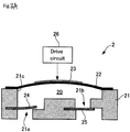
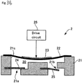
- FIGS. 3A and 3B are side cross-sectional views of the pump 2 illustrating an operating principle of the pump 2.
- the pump 2 includes a casing 21, a diaphragm 22, and a piezo element 23.
- a pump chamber 20 is arranged inside the casing 21, and a suction port 21a and an ejection port 21b are connected to the pump chamber 20 in the casing.
- a suction valve 24 configured to open and close the suction port 21a is attached to the port, and an ejection valve 25 configured to open and close the ejection port 21b is attached to the port.
- an opening 21c is arranged passing through the casing 21, and the diaphragm 22 is attached to the casing 21 so as to close the opening 21c.
- the piezo element 23 is attached to the diaphragm 22.
- the pump 2 further includes a drive circuit 26 configured to drive the piezo element 23.
- the drive circuit 26 vibrates the piezo element 23, thereby vibrating the diaphragm 22 up and down.
- the piezo element 23 is constituted by a thin film layer made of a piezoelectric material, and a pair of electrodes respectively arranged on a pair of end faces of the thin film layer, and is vibrated through the application of voltage from the drive circuit 26 to a portion between the electrodes.
- the drive circuit 26 is connected to the control unit 4, and the control unit 4 controls an operation of the drive circuit 26, thereby controlling vibration of the piezo element 23, and eventually controlling the ejecting operation of the pump 2.
- a time to drive (turn on) and stop (turn off) vibration of the piezo element 23, that is, the ejecting operation of the pump 2 is controlled by the control unit 4.
- the piezo element 23 When the piezo element 23 is vibrated to deform the diaphragm 22 so as to increase the volume of the pump chamber 20 as shown in FIG. 3A , the pressure inside the pump chamber 20 decreases, and thus the suction valve 24 is opened by being pulled into the pump chamber 20. Accordingly, the fluid in the tank 1 is sucked out via the suction port 21a into the pump chamber 20.
- the suction port 21a is connected to a first flow path L1, and is further connected via the first flow path L1 to the tank 1.
- the flow meter 3 of this embodiment is, but is not limited to, a flow meter using a MEMS technique.
- the flow meter 3 is arranged on the second flow path L2, and measures the flow rate of the fluid that is sent out from the pump 2 and flows through the second flow path L2.
- the flow meter 3 of this embodiment is, but is not limited to, a thermal flow meter.
- the control unit 4 is a microcomputer, and is constituted by a CPU, a ROM, a RAM, and the like.
- the pump system 100 further includes a non-volatile storage unit 6 connected to the control unit 4.
- the control unit 4 reads and executes a program 6a stored in the storage unit 6, thereby performing the above-described operations. Note that part or the whole of the program 6a may be stored in a ROM constituting the control unit 4.
- a target flow rate Tfr of the pump 2 can be set for the pump system 100.
- the set target flow rate Tfr is stored in the storage unit 6, and is referred to by the control unit 4 as appropriate.
- There is no particular limitation on the method for setting the target flow rate Tfr of the pump 2 and, for example, it is also possible that an input device such as a button or a switch is mounted in the pump system 100, and a user can input the target flow rate Tfr by operating the device.
- the control unit 4 is connectable to an external computer, and the target flow rate Tfr input by the user to the computer is transmitted from the computer to the control unit 4 and stored in the storage unit 6.
- Examples of the computer typically include a smartphone, a tablet computer, a desktop computer, and a laptop computer.
- communicative connection between the computer and the control unit 4 may be a wired connection using a cable or wireless connection according to a wireless communication standard such as Bluetooth (registered trademark).
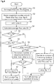
- FIG. 4 is a flowchart showing the flow of feedback control that controls the ejecting operation of the pump 2 based on the measured value Mfr of the flow meter 3, the feedback control being performed during the transporting operation.
- the user when driving the pump system 100, the user sets the target flow rate Tfr of the pump 2, for example, by operating an input device mounted in the pump system 100 or an external computer connected to the pump system 100, and stores the target flow rate in the storage unit 6. Furthermore, the user inputs a drive command to drive the pump system 100 to the control unit 4, for example, by operating the input device or the external computer.
- the control unit 4 Upon receiving input of the above-mentioned drive command, the control unit 4 reads the target flow rate Tfr of the pump 2 from the storage unit 6 (step SI). Furthermore, the control unit 4 resets an integration counter (hereinafter, referred to as a "cntr” as appropriate) to 0, and resets a stop flag (hereinafter, referred to as a "stop_flg” as appropriate) to 0 (step S2).
- an integration counter hereinafter, referred to as a "cntr” as appropriate
- stop_flg a stop flag
- the integration counter is a counter that measures the length of driving time after the pump system 100 is driven in response to input of the above-mentioned drive command, and is a counter that measures the number of unit sections passed.
- the control unit 4 decides on whether the ejecting operation of the pump 2 is to be driven (turned on) or stopped (turned off) for each unit section. Note that the ejecting operation of the pump 2 may be continuously driven throughout a plurality of successive unit sections, and, in a similar manner, the ejecting operation of the pump 2 may be continuously stopped throughout a plurality of successive unit sections.
- the pump 2 intermittently performs the ejecting operation, and repeatedly drives (turns on) and stops (turns off) the ejecting operation during driving of the pump system 100.
- the stop flag is a flag for giving an instruction to stop the ejecting operation of the pump 2 in a next unit section following the current unit section, where the flag is set to 1 in the case of stopping the ejecting operation and to 0 in the case of driving the ejecting operation.
- step S2 the control unit 4 increments the value of the integration counter by 1 (step S3). Note that steps S3 to S14 in FIG. 4 are loop processing that is repeatedly performed each time a unit section passes.
- the control unit 4 drives the flow meter 3 in each unit section, and causes the flow meter 3 to continuously measure the flow rate of the fluid ejected from the pump 2.
- the measured value Mfr of the flow rate measured by the flow meter 3 is sequentially transmitted from the flow meter 3 to the control unit 4.
- the control unit 4 calculates an average flow rate Afr of the fluid ejected from the pump 2 from when the pump system 100 is driven to the current point in time, based on the measured value Mfr received from the flow meter 3 (step S4).
- the average flow rate Afr can be calculated by averaging the measured value Mfr acquired from when the pump system 100 is driven to the current point in time.
- step S4 the control unit 4 refers to the value of the stop flag, and advances the procedure to step S6 if the value is 0 or to step S9 if the value is 1 (step S5).
- step S6 the control unit 4 compares the average flow rate Afr calculated in step S4 and the target flow rate Tfr read in step S1, and determines whether or not to stop the ejecting operation of the pump 2. More specifically, if the average flow rate Afr is not greater than the target flow rate Tfr, the control unit 4 determines to drive the ejecting operation in a next unit section following the current unit section (step S6), resets the stop flag to 0 (step S7), and drives the ejecting operation of the pump 2 using the drive circuit 26 (step S8).
- step S9 the control unit 4 acknowledges the number of unit sections during which the ejecting operation of the pump 2 is stopped (hereinafter, referred to as a "number of stopping sections" and indicated as "stop_num" as appropriate). More specifically, the control unit 4 determines whether or not the number of stopping sections has to be calculated, based on the value of the number of stopping sections.
- step S10 the value of the number of stopping sections is decremented by 1, after which, if the value of the number of stopping sections is still 1 or more (step S11), the ejecting operation of the pump 2 is stopped using the drive circuit 26 (step S12).
- step S11 the stop flag is reset to 0 (step S7), and the ejecting operation of the pump 2 is started using the drive circuit 26 (step S8).
- comparing the average flow rate Afr and the target flow rate Tfr in step S6 is the same as comparing the actual integral ejection amount specified based on the measured value Mfr and the target integral ejection amount specified based on the target flow rate Tfr.
- Tfr Afr * cntr + 0 * stop_num ⁇ / stop_num ⁇ + cntr
- stop_num' is a necessary number of unit sections during which the pump 2 is stopped in order to make the average flow rate Afr match the target flow rate Tfr, for the average flow rate Afr that is greater than the target flow rate Tfr.
- the average flow rate Afr is biased upward relative to the target flow rate Tfr, and, in order to make the average flow rate Afr uniform relative to the target flow rate Tfr on the upper and lower sides, it is desirable to stop the pump 2 during the number of unit sections that is twice the number obtained with stop num'. Accordingly, Equation 1 is obtained.
- step S13 the number of stopping sections indicating the length of the stopping section during which the ejecting operation of the pump 2 is stopped is decided based on the average flow rate Afr based on the measured value Mfr of the flow meter 3, the target flow rate Tfr set in advance, and the integration counter cntr indicating the driving time of the pump system 100.
- the number of stopping sections is decided on so as to cancel the ejection amount of fluid excessively ejected from the pump 2 from when the pump system 100 is driven to the current point in time.
- the excessive ejection amount means an excessive amount relative to the target integral ejection amount, contained in the actual integral ejection amount.
- step S13 the control unit 4 sets the stop flag to 1 (step S14), and then stops the ejecting operation of the pump 2 using the drive circuit 26 (step S12). After step S8 or S12, the procedure returns to step S3, and similar steps are repeated.
- FIG. 5 is an example of a graph showing a relationship between the actually measured flow rate of the fluid and the actual integral ejection amount of the fluid based thereon, and the time, in the case in which the feedback control according to this embodiment is performed.
- FIG. 5 shows an actual measurement line indicating the actually measured flow rate of the fluid and the integral ejection amount, and also shows a target line indicating the target integral ejection amount.
- the target flow rate is indicated by the dotted line
- lines indicating the upper and lower flow rate tolerance limits based on the target flow rate are respectively indicated by a dash-dotted line and a dash-double-dotted line.
- the actual measurement line is prevented from being excessively biased upward relative to the target line contrary to the case of FIG. 1 .
- the measured flow rate is, over time, unlikely to be out of the region defined by lines indicating the upper and lower flow rate tolerance limits. That is to say, in the example in FIG. 1 , the pump 2 is immediately driven when the actual measurement line becomes even slightly lower than the target line, and thus the actual measurement line is biased upward relative to the target line. On the other hand, in this embodiment, the pump 2 is not necessarily immediately driven when the actual measurement line becomes lower than the target line.
- the trumpet curve is one of evaluation items regarding the pump performance, and is a curve indicating the level of precision of an ejection amount of a pump with respect to a target value and the variability of a flow rate.
- the target flow rate Tfr is precisely achieved based on the improved trumpet curve. More specifically, the values of the maximum measurement error (Ep(max)) and the minimum measurement error (Ep(min)) obtained from the trumpet curve can be effectively made uniform.
- the fluid intermittently ejected from the pump 2 flows through the second flow path L2 and is sent into a patient by the needle 5 being inserted into a patient's body.
- a small or ultra-small pump using a MEMS technique was given as an example of the pump 2, but there is no limitation to this.
- a piezo pump was given as an example of the pump 2, but there is no limitation to this.
- Various types of pumps may be used as the pump 2.
- the fluid that is transported by the pump system 100 is not limited to a liquid, and may also be a gas.
Landscapes
- Engineering & Computer Science (AREA)
- Health & Medical Sciences (AREA)
- General Engineering & Computer Science (AREA)
- Mechanical Engineering (AREA)
- Public Health (AREA)
- Vascular Medicine (AREA)
- Hematology (AREA)
- Life Sciences & Earth Sciences (AREA)
- Animal Behavior & Ethology (AREA)
- General Health & Medical Sciences (AREA)
- Biomedical Technology (AREA)
- Veterinary Medicine (AREA)
- Anesthesiology (AREA)
- Heart & Thoracic Surgery (AREA)
- Computer Hardware Design (AREA)
- Physics & Mathematics (AREA)
- Fluid Mechanics (AREA)
- Control Of Positive-Displacement Pumps (AREA)
- Reciprocating Pumps (AREA)
- Control Of Non-Positive-Displacement Pumps (AREA)
- Infusion, Injection, And Reservoir Apparatuses (AREA)
Abstract
Description
- The disclosure relates to a pump system.
-
JP 2011-160868A Patent Literature 1") discloses a pump using a MEMS (micro electro mechanical systems) technique. According toPatent Literature 1, the flow rate of a fluid sent by the pump is measured by a flow rate sensor, on/off control of the pump is performed through feedback control that performs feedback of the flow rate measured by the flow rate sensor, and thus the pump is controlled such that a target flow rate is achieved. - When attempting to achieve a target flow rate of a pump through an intermittent operation of the pump as in
Patent Literature 1, control is often performed in which the ejection amount of fluid ejected by a current point in time and the ejection amount of fluid that is to be ejected by the current point in time are compared, and, if the former is smaller than the latter, the pump is turned on, or otherwise the pump is turned off. The former ejection amount can be calculated from the measured flow rate, and the latter ejection amount can be set from the target flow rate. -
FIG. 1 shows an example of a graph showing a relationship between the measured flow rate of the fluid and the actual integral ejection amount of the fluid based thereon (which can be calculated as an integral value of the measured flow rate) and the time, in the case in which the above-described control is performed.FIG. 1 shows a graph of the measured flow rate of the fluid and a graph of the actual integral ejection amount of the fluid based thereon (hereinafter, referred to as an "actual measurement line"), and also shows a line indicating the integral ejection amount of the fluid that is to be ejected according to the target flow rate (hereinafter, referred to as a "target line"). Furthermore, the target flow rate is indicated by the dotted line, and lines indicating the upper and lower flow rate tolerance limits based on the target flow rate are respectively indicated by a dash-dotted line and a dash-double-dotted line. - As is seen from
FIG. 1 , in the case in which the above-described intermittent operation is performed, if the actual measurement line becomes even slightly lower than the target line, the pump is driven, and thus the actual measurement line becomes higher than the target line. Then, the pump is turned off, after which, if the actual measurement line again becomes even slightly lower than the target line, the pump is again driven, and the same operation is repeated. - Accordingly, in the above-described control, as shown in
FIG. 1 , the target line is not at the center of the actual measurement line, and the actual measurement line is biased upward relative to the target line. Furthermore, the measured flow rate may be frequently higher than the upper tolerance limit. As a result, in the above-described control, the trumpet curve deteriorates. Note that the trumpet curve is one of evaluation items regarding the pump performance as defined in JIS (Japanese Industrial Standards) T 0601-2-24:2018, and is obtained by plotting a maximum value of errors on the upper side and a minimum value of errors on the lower side of average measured flow rates of a plurality of measurement time periods (which are respectively referred to as a "maximum measurement error (Ep(max))" and a "minimum measurement error (Ep(min))") relative to the average measured flow rate over the entire measurement section, as well as a difference between the target flow rate and the average measured flow rate over the entire measurement section. Thus, the longer the measurement time periods, the more averaged the measured flow rate, and thus error values are smaller and a graph thereof has a similar shape to that of an instrument called trumpet. Accordingly, the trumpet curve is a curve indicating the level of precision of an ejection amount of a pump with respect to a target value and the variability of a flow rate. - It is an object of the disclosure to provide a pump system with an improved trumpet curve.
- A pump system according to a first aspect is a pump system including: a pump configured to intermittently perform an ejecting operation that ejects a fluid; a flow meter configured to measure a flow rate of the fluid ejected from the pump; and a control unit connected to the pump and the flow meter, configured to decide on a length of a stopping section during which the ejecting operation is stopped such that an ejection amount of fluid excessively ejected from the pump is canceled, based on a measured flow rate, which is the flow rate measured by the flow meter, and a target flow rate of the pump set in advance, and configured to control the pump so as to stop the ejecting operation according to the length of the stopping section.
- A pump system according to a second aspect is the pump system according to the first aspect, wherein the control unit determines whether or not to stop the ejecting operation, by comparing an ejection amount of fluid ejected from the pump based on the measured flow rate and an ejection amount of fluid that is to be ejected from the pump based on the target flow rate, and decides on the length of the stopping section in a case of stopping the ejecting operation.
- A pump system according to a third aspect is the pump system according to the second aspect, wherein it is determined to stop the ejecting operation in a case in which the ejection amount based on the measured flow rate is larger than the ejection amount based on the target flow rate.
- According to the above-described aspects, a length of a stopping section during which the ejecting operation of a pump is stopped is decided on such that an ejection amount of fluid excessively ejected from the pump is canceled, based on a measured flow rate measured by a flow meter and a target flow rate of the pump set in advance. Then, the pump is controlled such that the ejecting operation of the pump is stopped according to the decided length of the stopping section. Accordingly, the target line of the flow rate becomes closer to the center of the actual measurement line, and the actual measurement line is prevented from being excessively biased upward relative to the target line. As a result, the trumpet curve of the pump system is improved.
- Further embodiments of the invention are described in the following description of the figures and/or the dependent claims attached to this specification. The invention will be explained in the following in detail by means of embodiments and with reference to the drawing in which is shown:
-
FIG. 1 is an example of a graph showing a relationship between the integral ejection amount of a fluid and the time according to a related technique. -
FIG. 2 is a configuration diagram of a pump system according to an embodiment of the disclosure. -
FIG. 3A is a side cross-sectional view of the pump during suction. -
FIG. 3B is a side cross-sectional view of the pump during ejection. -
FIG. 4 is a flowchart showing the flow of feedback control that controls an ejecting operation of the pump based on a measured value of a flow meter. -
FIG. 5 is an example of a graph showing a relationship between the integral ejection amount of the fluid and the time according to the embodiment of the disclosure. - In the following the same reference numerals will be used for parts having the same or equivalent function. Any statements made having regard to the direction of a component are made relative to the position shown in the drawing and can naturally vary in the actual position of application.
- Hereinafter, a pump system according to an embodiment of the disclosure will be described with reference to the drawings.
-
FIG. 2 shows a configuration diagram of apump system 100 according to this embodiment. As shown inFIG. 2 , thepump system 100 includes atank 1 configured to store a fluid, and apump 2 arranged downstream of thetank 1 and configured to suck and eject the fluid in thetank 1. In this description, the upstream and the downstream are defined according to the flow of a fluid. Thepump 2 intermittently performs an ejecting operation that ejects the fluid. - Furthermore, the
pump system 100 further includes aflow meter 3 configured to measure the flow rate of the fluid ejected from thepump 2, and a control unit 4 connected to thepump 2 and theflow meter 3. The control unit 4 controls the fluid transporting operation that is performed by thepump system 100. At this time, the control unit 4 performs feedback control that controls the ejecting operation of thepump 2, based on a measured value Mfr of the flow rate measured by theflow meter 3. - The
pump 2 of this embodiment is, but is not limited to, a small or ultra-small pump that enables a fluid to flow at a very low flow rate using a MEMS (micro electro mechanical systems) technique. Quantitatively, thepump 2 may be a small pump whose target flow rate is set to 600 µl/h or less. However, thepump 2 may also be a smaller pump whose target flow rate is set to 400 µl/h or less, 200 µl/h or less, 100 µl/h or less, 80 µl/h or less, 60 µl/h or less, 40 µl/h or less, or 20 µl/h or less. - Furthermore, the
pump system 100 of this embodiment is, but is not limited to, a system configured to transport a medical fluid such as insulin. Thus, in this embodiment, aneedle 5 is connected downstream of thepump 2, and the medical fluid in thetank 1 is given to a patient by theneedle 5 being inserted into a patient's arm. - Furthermore, the
pump 2 of this embodiment is, but is not limited to, a piezo pump.FIGS. 3A and3B are side cross-sectional views of thepump 2 illustrating an operating principle of thepump 2. As shown inFIGS. 3A and3B , thepump 2 includes acasing 21, adiaphragm 22, and apiezo element 23. Apump chamber 20 is arranged inside thecasing 21, and asuction port 21a and anejection port 21b are connected to thepump chamber 20 in the casing. Asuction valve 24 configured to open and close thesuction port 21a is attached to the port, and anejection valve 25 configured to open and close theejection port 21b is attached to the port. Furthermore, an opening 21c is arranged passing through thecasing 21, and thediaphragm 22 is attached to thecasing 21 so as to close the opening 21c. - The
piezo element 23 is attached to thediaphragm 22. Thepump 2 further includes adrive circuit 26 configured to drive thepiezo element 23. Thedrive circuit 26 vibrates thepiezo element 23, thereby vibrating thediaphragm 22 up and down. Thepiezo element 23 is constituted by a thin film layer made of a piezoelectric material, and a pair of electrodes respectively arranged on a pair of end faces of the thin film layer, and is vibrated through the application of voltage from thedrive circuit 26 to a portion between the electrodes. Thedrive circuit 26 is connected to the control unit 4, and the control unit 4 controls an operation of thedrive circuit 26, thereby controlling vibration of thepiezo element 23, and eventually controlling the ejecting operation of thepump 2. A time to drive (turn on) and stop (turn off) vibration of thepiezo element 23, that is, the ejecting operation of thepump 2 is controlled by the control unit 4. - When the
piezo element 23 is vibrated to deform thediaphragm 22 so as to increase the volume of thepump chamber 20 as shown inFIG. 3A , the pressure inside thepump chamber 20 decreases, and thus thesuction valve 24 is opened by being pulled into thepump chamber 20. Accordingly, the fluid in thetank 1 is sucked out via thesuction port 21a into thepump chamber 20. Thesuction port 21a is connected to a first flow path L1, and is further connected via the first flow path L1 to thetank 1. - On the other hand, when the
piezo element 23 is vibrated to deform thediaphragm 22 so as to reduce the volume of thepump chamber 20 as shown inFIG. 3B , the pressure inside thepump chamber 20 increases, and thus theejection valve 25 is opened by being pushed to the outside of thepump chamber 20. Furthermore, at this time, thesuction valve 24 is closed by being pushed so as to close thesuction port 21a. Accordingly, a fluid is ejected from thepump chamber 20 via theejection port 21b. Theejection port 21b is connected to a second flow path L2, and the fluid ejected from thepump chamber 20 flows to the downstream side via the second flow path L2 and ultimately reaches theneedle 5. Note that, when thepiezo element 23 is next vibrated as shown inFIG. 3A , thesuction valve 24 is opened, and theejection valve 25 is closed by being pulled so as to close theejection port 21b. - The
flow meter 3 of this embodiment is, but is not limited to, a flow meter using a MEMS technique. Theflow meter 3 is arranged on the second flow path L2, and measures the flow rate of the fluid that is sent out from thepump 2 and flows through the second flow path L2. Furthermore, theflow meter 3 of this embodiment is, but is not limited to, a thermal flow meter. - The control unit 4 is a microcomputer, and is constituted by a CPU, a ROM, a RAM, and the like. The
pump system 100 further includes a non-volatile storage unit 6 connected to the control unit 4. The control unit 4 reads and executes aprogram 6a stored in the storage unit 6, thereby performing the above-described operations. Note that part or the whole of theprogram 6a may be stored in a ROM constituting the control unit 4. - A target flow rate Tfr of the
pump 2 can be set for thepump system 100. The set target flow rate Tfr is stored in the storage unit 6, and is referred to by the control unit 4 as appropriate. There is no particular limitation on the method for setting the target flow rate Tfr of thepump 2, and, for example, it is also possible that an input device such as a button or a switch is mounted in thepump system 100, and a user can input the target flow rate Tfr by operating the device. Alternatively, it is also possible that the control unit 4 is connectable to an external computer, and the target flow rate Tfr input by the user to the computer is transmitted from the computer to the control unit 4 and stored in the storage unit 6. It is assumed that examples of the computer typically include a smartphone, a tablet computer, a desktop computer, and a laptop computer. There is no particular limitation on the form of communicative connection between the computer and the control unit 4, but it may be a wired connection using a cable or wireless connection according to a wireless communication standard such as Bluetooth (registered trademark). - Next, a fluid transporting operation that is performed by the
pump system 100 will be described in detail.FIG. 4 is a flowchart showing the flow of feedback control that controls the ejecting operation of thepump 2 based on the measured value Mfr of theflow meter 3, the feedback control being performed during the transporting operation. - First, when driving the
pump system 100, the user sets the target flow rate Tfr of thepump 2, for example, by operating an input device mounted in thepump system 100 or an external computer connected to thepump system 100, and stores the target flow rate in the storage unit 6. Furthermore, the user inputs a drive command to drive thepump system 100 to the control unit 4, for example, by operating the input device or the external computer. - Upon receiving input of the above-mentioned drive command, the control unit 4 reads the target flow rate Tfr of the
pump 2 from the storage unit 6 (step SI). Furthermore, the control unit 4 resets an integration counter (hereinafter, referred to as a "cntr" as appropriate) to 0, and resets a stop flag (hereinafter, referred to as a "stop_flg" as appropriate) to 0 (step S2). - The integration counter is a counter that measures the length of driving time after the
pump system 100 is driven in response to input of the above-mentioned drive command, and is a counter that measures the number of unit sections passed. As will be described later, the control unit 4 decides on whether the ejecting operation of thepump 2 is to be driven (turned on) or stopped (turned off) for each unit section. Note that the ejecting operation of thepump 2 may be continuously driven throughout a plurality of successive unit sections, and, in a similar manner, the ejecting operation of thepump 2 may be continuously stopped throughout a plurality of successive unit sections. In either case, thepump 2 intermittently performs the ejecting operation, and repeatedly drives (turns on) and stops (turns off) the ejecting operation during driving of thepump system 100. The stop flag is a flag for giving an instruction to stop the ejecting operation of thepump 2 in a next unit section following the current unit section, where the flag is set to 1 in the case of stopping the ejecting operation and to 0 in the case of driving the ejecting operation. - After step S2, the control unit 4 increments the value of the integration counter by 1 (step S3). Note that steps S3 to S14 in
FIG. 4 are loop processing that is repeatedly performed each time a unit section passes. - Furthermore, when the
pump system 100 is driven, the control unit 4 drives theflow meter 3 in each unit section, and causes theflow meter 3 to continuously measure the flow rate of the fluid ejected from thepump 2. The measured value Mfr of the flow rate measured by theflow meter 3 is sequentially transmitted from theflow meter 3 to the control unit 4. After step S3, the control unit 4 calculates an average flow rate Afr of the fluid ejected from thepump 2 from when thepump system 100 is driven to the current point in time, based on the measured value Mfr received from the flow meter 3 (step S4). The average flow rate Afr can be calculated by averaging the measured value Mfr acquired from when thepump system 100 is driven to the current point in time. - After step S4, the control unit 4 refers to the value of the stop flag, and advances the procedure to step S6 if the value is 0 or to step S9 if the value is 1 (step S5). In step S6, the control unit 4 compares the average flow rate Afr calculated in step S4 and the target flow rate Tfr read in step S1, and determines whether or not to stop the ejecting operation of the
pump 2. More specifically, if the average flow rate Afr is not greater than the target flow rate Tfr, the control unit 4 determines to drive the ejecting operation in a next unit section following the current unit section (step S6), resets the stop flag to 0 (step S7), and drives the ejecting operation of thepump 2 using the drive circuit 26 (step S8). - On the other hand, if the value of the stop flag is 1 in step S5 or if the average flow rate Afr is greater than the target flow rate Tfr in step S6, the ejecting operation of the
pump 2 has to be stopped in one next unit section following the current unit section or in one next unit and a plurality of successive unit sections thereafter, and thus the control unit 4 advances the procedure to step S9. In step S9, the control unit 4 acknowledges the number of unit sections during which the ejecting operation of thepump 2 is stopped (hereinafter, referred to as a "number of stopping sections" and indicated as "stop_num" as appropriate). More specifically, the control unit 4 determines whether or not the number of stopping sections has to be calculated, based on the value of the number of stopping sections. - The procedure advances to step S13 if the number of stopping sections is 0 in step S9, or to step S10 if the number of stopping sections is 1 or more. In step S10, the value of the number of stopping sections is decremented by 1, after which, if the value of the number of stopping sections is still 1 or more (step S11), the ejecting operation of the
pump 2 is stopped using the drive circuit 26 (step S12). On the other hand, if the number of stopping sections is 0 in step S11, the stop flag is reset to 0 (step S7), and the ejecting operation of thepump 2 is started using the drive circuit 26 (step S8). - Incidentally, it is possible to convert the above-described average flow rate Afr into the ejection amount of fluid ejected from the
pump 2 from when thepump system 100 is driven to the current point in time (hereinafter, referred to as an "actual integral ejection amount"), by considering the length of driving time of thepump system 100 by referring to the value of the integration counter, for example. In a similar manner, it is also possible to convert the above-described target flow rate Tfr into the ejection amount of fluid that is to be ejected from thepump 2 from when thepump system 100 is driven to the current point in time according to the target flow rate Tfr (hereinafter, referred to as a "target integral ejection amount"). Accordingly, it can be said that comparing the average flow rate Afr and the target flow rate Tfr in step S6 is the same as comparing the actual integral ejection amount specified based on the measured value Mfr and the target integral ejection amount specified based on the target flow rate Tfr. - As described above, step S9, in which the number of stopping sections is acknowledged, is performed in the case in which it is determined to stop the ejecting operation in a next unit section following the current unit section. If the number of stopping sections is 0 in step S9, the control unit 4 decides on the length of the stopping section of the ejecting operation (step S13). In this embodiment, the length of the stopping section is calculated as the number of stopping sections. More specifically, the number of stopping sections is calculated according to
Equation 1 below. Note that, inEquation 1, int() is a function that returns the largest integer that is not larger than the numerical value in ().
- As a description of the meaning of
Equation 1, first, the target flow rate Tfr is achieved whenEquation 2 below holds up.
- Note that "stop_num' " is a necessary number of unit sections during which the
pump 2 is stopped in order to make the average flow rate Afr match the target flow rate Tfr, for the average flow rate Afr that is greater than the target flow rate Tfr. - Then, stop_num' = Afr*cntr/Tfr-cntr is obtained by transforming
Equation 2, and stop num' = int(Afr*cntr/Tfr) -cntr is obtained by expressing the first term on the right hand side as an integer. At this time, the average flow rate Afr is biased upward relative to the target flow rate Tfr, and, in order to make the average flow rate Afr uniform relative to the target flow rate Tfr on the upper and lower sides, it is desirable to stop thepump 2 during the number of unit sections that is twice the number obtained with stop num'. Accordingly,Equation 1 is obtained. - As described above, in step S13, the number of stopping sections indicating the length of the stopping section during which the ejecting operation of the
pump 2 is stopped is decided based on the average flow rate Afr based on the measured value Mfr of theflow meter 3, the target flow rate Tfr set in advance, and the integration counter cntr indicating the driving time of thepump system 100. At this time, as is clear fromEquation 1, the number of stopping sections is decided on so as to cancel the ejection amount of fluid excessively ejected from thepump 2 from when thepump system 100 is driven to the current point in time. The excessive ejection amount means an excessive amount relative to the target integral ejection amount, contained in the actual integral ejection amount. - After step S13, the control unit 4 sets the stop flag to 1 (step S14), and then stops the ejecting operation of the
pump 2 using the drive circuit 26 (step S12). After step S8 or S12, the procedure returns to step S3, and similar steps are repeated. -
FIG. 5 is an example of a graph showing a relationship between the actually measured flow rate of the fluid and the actual integral ejection amount of the fluid based thereon, and the time, in the case in which the feedback control according to this embodiment is performed. As inFIG. 1 ,FIG. 5 shows an actual measurement line indicating the actually measured flow rate of the fluid and the integral ejection amount, and also shows a target line indicating the target integral ejection amount. Furthermore, the target flow rate is indicated by the dotted line, and lines indicating the upper and lower flow rate tolerance limits based on the target flow rate are respectively indicated by a dash-dotted line and a dash-double-dotted line. - As is seen from the comparison between
FIGS. 1 and5 , in this embodiment, the actual measurement line is prevented from being excessively biased upward relative to the target line contrary to the case ofFIG. 1 . Furthermore, the measured flow rate is, over time, unlikely to be out of the region defined by lines indicating the upper and lower flow rate tolerance limits. That is to say, in the example inFIG. 1 , thepump 2 is immediately driven when the actual measurement line becomes even slightly lower than the target line, and thus the actual measurement line is biased upward relative to the target line. On the other hand, in this embodiment, thepump 2 is not necessarily immediately driven when the actual measurement line becomes lower than the target line. That is to say, in this embodiment, after the stopped state of thepump 2 is maintained for a while as necessary until the ejection amount of fluid excessively ejected from thepump 2 is canceled, thepump 2 is driven again. As a result, the target line becomes closer to the center of the actual measurement line, and thus the trumpet curve of thepump system 100 is improved. Note that the trumpet curve is one of evaluation items regarding the pump performance, and is a curve indicating the level of precision of an ejection amount of a pump with respect to a target value and the variability of a flow rate. In this embodiment, the target flow rate Tfr is precisely achieved based on the improved trumpet curve. More specifically, the values of the maximum measurement error (Ep(max)) and the minimum measurement error (Ep(min)) obtained from the trumpet curve can be effectively made uniform. - While the above-described feedback control is performed, the fluid intermittently ejected from the
pump 2 flows through the second flow path L2 and is sent into a patient by theneedle 5 being inserted into a patient's body. In this embodiment, it is possible to precisely give a desired amount of fluid to the patient's body, based on the improved trumpet curve. - In the description above, an embodiment of the disclosure has been described, but the disclosure is not limited to the foregoing embodiment, and can encompass various modifications without departing from the gist thereof. For example, the following modifications are possible.
- In the foregoing embodiment, a small or ultra-small pump using a MEMS technique was given as an example of the
pump 2, but there is no limitation to this. Furthermore, in the foregoing embodiment, a piezo pump was given as an example of thepump 2, but there is no limitation to this. Various types of pumps may be used as thepump 2. - The fluid that is transported by the
pump system 100 is not limited to a liquid, and may also be a gas. -
- 100
- Pump system
- 1
- Tank
- 2
- Pump
- 3
- Flow meter
- 4
- Control unit
- 5
- Needle
- 6
- Storage unit
Claims (15)
- A pump system (100) comprising:a pump (2) configured to intermittently perform an ejecting operation that ejects a fluid;a flow meter (3) configured to measure a flow rate of the fluid ejected from the pump; anda control unit (4) connected to the pump (2) and the flow meter (3), configured to decide on a length of a stopping section during which the ejecting operation is stopped such that an ejection amount of fluid excessively ejected from the pump (2) is canceled, based on a measured flow rate, which is the flow rate measured by the flow meter (3), and a target flow rate of the pump (2) set in advance, and configured to control the pump (2) so as to stop the ejecting operation according to the length of the stopping section.
- The pump system (100) according to claim 1, wherein the control unit (4) determines whether or not to stop the ejecting operation, by comparing an ejection amount of fluid ejected from the pump (2) based on the measured flow rate and an ejection amount of fluid that is to be ejected from the pump (2) based on the target flow rate, and decides on the length of the stopping section in a case of stopping the ejecting operation.
- The pump system (100) according to claim 2, wherein it is determined to stop the ejecting operation in a case in which the ejection amount based on the measured flow rate is larger than the ejection amount based on the target flow rate.
- The pump system (100) according to one of claims 1 to 3, wherein the voltage is a control parameter for increasing or decreasing an ejection amount of the pump (2); and/or
wherein the flow rate of the pump (2) is controlled by increasing or decreasing an ejection amount of fluid. - The pump system (100) according to one of claims 1 to 4, wherein the pump (2) includes a casing (21), a diaphragm (22), and a piezo element (23).
- The pump system (100) according to claim 5, wherein a pump chamber (20) is arranged inside the casing (21), and a suction port (21a) and an ejection port (21b) are connected to the pump chamber (20) in the casing (21).
- The pump system (100) according to claims 5 and 6, wherein a suction valve (24) configured to open and close the suction port (21a) is attached to the suction port (21a), and an ejection valve (25) configured to open and close the ejection port (21b) is attached to the ejection port (21b).
- The pump system (100) according to one of claims 5 to 7, wherein an opening (21c) is arranged passing through the casing (21), and wherein the diaphragm (22) is attached to the casing (21) so as to close the opening (21c).
- The pump system (100) according to one of claims 5 to 8, wherein the piezo element (23) is attached to the diaphragm (22).
- The pump system (100) according to one of claims 5 to 9, wherein the pump (2) further includes a drive circuit (26) configured to drive the piezo element (23).
- The pump system (100) according to claim 10, wherein the drive circuit (26) is configured to vibrate the piezo element (23).
- The pump system (100) according to one of claims 5 to 11, wherein the piezo element (23) comprises a thin film layer made of a piezoelectric material, and a pair of electrodes respectively arranged on a pair of end faces of the thin film layer, and wherein a voltage V can be applied from the drive circuit (26) to a portion between the electrodes.
- The pump system (100) according to one of claims 9 to 12, wherein the drive circuit (26) is connected to the control unit (4), and the voltage (V) that is applied via the drive circuit (26) to the piezo element (23) is controlled by the control unit (4).
- The pump system (100) according to one of claims 1 to 13, wherein the control unit (4) is connectable to an external computer, and the target flow rate input by a user to the computer is transmitted from the computer to the control unit (4) and is stored in a storage unit (6).
- The pump system (100) according to one of claims 1 to 14, wherein the control unit (4) is a microcomputer, and comprises at least one of the following: a CPU, a ROM, a RAM, and the like.
Applications Claiming Priority (1)
| Application Number | Priority Date | Filing Date | Title |
|---|---|---|---|
| JP2020070046A JP2021167575A (en) | 2020-04-08 | 2020-04-08 | Pump system |
Publications (2)
| Publication Number | Publication Date |
|---|---|
| EP3892858A2 true EP3892858A2 (en) | 2021-10-13 |
| EP3892858A3 EP3892858A3 (en) | 2021-11-10 |
Family
ID=75426491
Family Applications (1)
| Application Number | Title | Priority Date | Filing Date |
|---|---|---|---|
| EP21167221.7A Withdrawn EP3892858A3 (en) | 2020-04-08 | 2021-04-07 | Pump system |
Country Status (4)
| Country | Link |
|---|---|
| US (1) | US20210316064A1 (en) |
| EP (1) | EP3892858A3 (en) |
| JP (1) | JP2021167575A (en) |
| CN (1) | CN113494442A (en) |
Citations (1)
| Publication number | Priority date | Publication date | Assignee | Title |
|---|---|---|---|---|
| JP2011160868A (en) | 2010-02-05 | 2011-08-25 | Ricoh Co Ltd | Flow rate control apparatus and pump apparatus |
Family Cites Families (5)
| Publication number | Priority date | Publication date | Assignee | Title |
|---|---|---|---|---|
| US5205819A (en) * | 1989-05-11 | 1993-04-27 | Bespak Plc | Pump apparatus for biomedical use |
| US6589229B1 (en) * | 2000-07-31 | 2003-07-08 | Becton, Dickinson And Company | Wearable, self-contained drug infusion device |
| US7029456B2 (en) * | 2003-10-15 | 2006-04-18 | Baxter International Inc. | Medical fluid therapy flow balancing and synchronization system |
| JP4419790B2 (en) * | 2004-10-20 | 2010-02-24 | パナソニック電工株式会社 | Piezoelectric diaphragm pump |
| JP4591521B2 (en) * | 2008-02-18 | 2010-12-01 | ソニー株式会社 | Electronic device having a piezoelectric pump |
-
2020
- 2020-04-08 JP JP2020070046A patent/JP2021167575A/en active Pending
-
2021
- 2021-04-06 CN CN202110368773.5A patent/CN113494442A/en active Pending
- 2021-04-07 US US17/224,522 patent/US20210316064A1/en not_active Abandoned
- 2021-04-07 EP EP21167221.7A patent/EP3892858A3/en not_active Withdrawn
Patent Citations (1)
| Publication number | Priority date | Publication date | Assignee | Title |
|---|---|---|---|---|
| JP2011160868A (en) | 2010-02-05 | 2011-08-25 | Ricoh Co Ltd | Flow rate control apparatus and pump apparatus |
Also Published As
| Publication number | Publication date |
|---|---|
| JP2021167575A (en) | 2021-10-21 |
| EP3892858A3 (en) | 2021-11-10 |
| US20210316064A1 (en) | 2021-10-14 |
| CN113494442A (en) | 2021-10-12 |
Similar Documents
| Publication | Publication Date | Title |
|---|---|---|
| EP3696412B1 (en) | Tube pump system and method for controlling the tube pump system | |
| CN101187446B (en) | Liquid medicine supply system and liquid medicine supply control device | |
| EP3296570B1 (en) | Tube pump system and method for controlling the tube pump system | |
| JP7372245B2 (en) | Device and method for automatic liquid transfer optimized dispensing | |
| JP2011208598A (en) | Chemical supply system | |
| US20120116348A1 (en) | Liquid medicine injection amount adjusting method, liquid medicine injection amount adjusting apparatus, and liquid medicine injecting system | |
| US10124096B2 (en) | Suction device | |
| JP5888478B1 (en) | Aspirator or pressurizer | |
| KR102152048B1 (en) | Pressure type flow control device and flow self-diagnosis method | |
| JP2009534756A (en) | Fluid-specific amount of flow controller delivery | |
| US11193480B2 (en) | Exhalation measurement device, and control method | |
| CN110088472A (en) | The positive displacement pump and haemodialysis equipment and its method of control of medical use liquid | |
| CN115364305A (en) | Infusion pump system, infusion pump monitoring system and method | |
| US10398809B2 (en) | Suction device | |
| US20210316064A1 (en) | Pump system | |
| EP2848218B1 (en) | Liquid ejecting apparatus and medical device | |
| EP3892857A2 (en) | Pump system | |
| EP3225264A1 (en) | Medication mechanism | |
| EP4036410B1 (en) | Accurate volume dispensing using pump and flow sensor | |
| EP3617507A1 (en) | Pressure control device and pressure using device | |
| JP6821270B2 (en) | Dosing mechanism | |
| EP3225267B1 (en) | Drug administration mechanism and pump unit for drug administration mechanism | |
| CN104414710A (en) | Liquid ejection device and medical apparatus | |
| EP3998119B1 (en) | Pipette | |
| US20240426287A1 (en) | Fluid control system |
Legal Events
| Date | Code | Title | Description |
|---|---|---|---|
| PUAI | Public reference made under article 153(3) epc to a published international application that has entered the european phase |
Free format text: ORIGINAL CODE: 0009012 |
|
| STAA | Information on the status of an ep patent application or granted ep patent |
Free format text: STATUS: THE APPLICATION HAS BEEN PUBLISHED |
|
| PUAL | Search report despatched |
Free format text: ORIGINAL CODE: 0009013 |
|
| AK | Designated contracting states |
Kind code of ref document: A2 Designated state(s): AL AT BE BG CH CY CZ DE DK EE ES FI FR GB GR HR HU IE IS IT LI LT LU LV MC MK MT NL NO PL PT RO RS SE SI SK SM TR |
|
| AK | Designated contracting states |
Kind code of ref document: A3 Designated state(s): AL AT BE BG CH CY CZ DE DK EE ES FI FR GB GR HR HU IE IS IT LI LT LU LV MC MK MT NL NO PL PT RO RS SE SI SK SM TR |
|
| RIC1 | Information provided on ipc code assigned before grant |
Ipc: F04B 49/06 20060101ALI20211002BHEP Ipc: F04B 43/04 20060101ALI20211002BHEP Ipc: F04B 49/20 20060101AFI20211002BHEP |
|
| STAA | Information on the status of an ep patent application or granted ep patent |
Free format text: STATUS: THE APPLICATION IS DEEMED TO BE WITHDRAWN |
|
| 18D | Application deemed to be withdrawn |
Effective date: 20220511 |