EP3892856A1 - Displacement control valve - Google Patents
Displacement control valve Download PDFInfo
- Publication number
- EP3892856A1 EP3892856A1 EP19894059.5A EP19894059A EP3892856A1 EP 3892856 A1 EP3892856 A1 EP 3892856A1 EP 19894059 A EP19894059 A EP 19894059A EP 3892856 A1 EP3892856 A1 EP 3892856A1
- Authority
- EP
- European Patent Office
- Prior art keywords
- valve
- valve body
- main
- control
- port
- Prior art date
- Legal status (The legal status is an assumption and is not a legal conclusion. Google has not performed a legal analysis and makes no representation as to the accuracy of the status listed.)
- Granted
Links
Images




Classifications
-
- F—MECHANICAL ENGINEERING; LIGHTING; HEATING; WEAPONS; BLASTING
- F04—POSITIVE - DISPLACEMENT MACHINES FOR LIQUIDS; PUMPS FOR LIQUIDS OR ELASTIC FLUIDS
- F04B—POSITIVE-DISPLACEMENT MACHINES FOR LIQUIDS; PUMPS
- F04B27/00—Multi-cylinder pumps specially adapted for elastic fluids and characterised by number or arrangement of cylinders
- F04B27/08—Multi-cylinder pumps specially adapted for elastic fluids and characterised by number or arrangement of cylinders having cylinders coaxial with, or parallel or inclined to, main shaft axis
- F04B27/14—Control
- F04B27/16—Control of pumps with stationary cylinders
- F04B27/18—Control of pumps with stationary cylinders by varying the relative positions of a swash plate and a cylinder block
-
- F—MECHANICAL ENGINEERING; LIGHTING; HEATING; WEAPONS; BLASTING
- F16—ENGINEERING ELEMENTS AND UNITS; GENERAL MEASURES FOR PRODUCING AND MAINTAINING EFFECTIVE FUNCTIONING OF MACHINES OR INSTALLATIONS; THERMAL INSULATION IN GENERAL
- F16K—VALVES; TAPS; COCKS; ACTUATING-FLOATS; DEVICES FOR VENTING OR AERATING
- F16K15/00—Check valves
- F16K15/02—Check valves with guided rigid valve members
- F16K15/025—Check valves with guided rigid valve members the valve being loaded by a spring
- F16K15/026—Check valves with guided rigid valve members the valve being loaded by a spring the valve member being a movable body around which the medium flows when the valve is open
-
- F—MECHANICAL ENGINEERING; LIGHTING; HEATING; WEAPONS; BLASTING
- F04—POSITIVE - DISPLACEMENT MACHINES FOR LIQUIDS; PUMPS FOR LIQUIDS OR ELASTIC FLUIDS
- F04B—POSITIVE-DISPLACEMENT MACHINES FOR LIQUIDS; PUMPS
- F04B27/00—Multi-cylinder pumps specially adapted for elastic fluids and characterised by number or arrangement of cylinders
- F04B27/08—Multi-cylinder pumps specially adapted for elastic fluids and characterised by number or arrangement of cylinders having cylinders coaxial with, or parallel or inclined to, main shaft axis
- F04B27/10—Multi-cylinder pumps specially adapted for elastic fluids and characterised by number or arrangement of cylinders having cylinders coaxial with, or parallel or inclined to, main shaft axis having stationary cylinders
- F04B27/1009—Distribution members
-
- F—MECHANICAL ENGINEERING; LIGHTING; HEATING; WEAPONS; BLASTING
- F04—POSITIVE - DISPLACEMENT MACHINES FOR LIQUIDS; PUMPS FOR LIQUIDS OR ELASTIC FLUIDS
- F04B—POSITIVE-DISPLACEMENT MACHINES FOR LIQUIDS; PUMPS
- F04B27/00—Multi-cylinder pumps specially adapted for elastic fluids and characterised by number or arrangement of cylinders
- F04B27/08—Multi-cylinder pumps specially adapted for elastic fluids and characterised by number or arrangement of cylinders having cylinders coaxial with, or parallel or inclined to, main shaft axis
- F04B27/0873—Component parts, e.g. sealings; Manufacturing or assembly thereof
- F04B27/0895—Component parts, e.g. sealings; Manufacturing or assembly thereof driving means
-
- F—MECHANICAL ENGINEERING; LIGHTING; HEATING; WEAPONS; BLASTING
- F04—POSITIVE - DISPLACEMENT MACHINES FOR LIQUIDS; PUMPS FOR LIQUIDS OR ELASTIC FLUIDS
- F04B—POSITIVE-DISPLACEMENT MACHINES FOR LIQUIDS; PUMPS
- F04B27/00—Multi-cylinder pumps specially adapted for elastic fluids and characterised by number or arrangement of cylinders
- F04B27/08—Multi-cylinder pumps specially adapted for elastic fluids and characterised by number or arrangement of cylinders having cylinders coaxial with, or parallel or inclined to, main shaft axis
- F04B27/14—Control
- F04B27/16—Control of pumps with stationary cylinders
- F04B27/18—Control of pumps with stationary cylinders by varying the relative positions of a swash plate and a cylinder block
- F04B27/1804—Controlled by crankcase pressure
-
- F—MECHANICAL ENGINEERING; LIGHTING; HEATING; WEAPONS; BLASTING
- F04—POSITIVE - DISPLACEMENT MACHINES FOR LIQUIDS; PUMPS FOR LIQUIDS OR ELASTIC FLUIDS
- F04B—POSITIVE-DISPLACEMENT MACHINES FOR LIQUIDS; PUMPS
- F04B35/00—Piston pumps specially adapted for elastic fluids and characterised by the driving means to their working members, or by combination with, or adaptation to, specific driving engines or motors, not otherwise provided for
- F04B35/04—Piston pumps specially adapted for elastic fluids and characterised by the driving means to their working members, or by combination with, or adaptation to, specific driving engines or motors, not otherwise provided for the means being electric
- F04B35/045—Piston pumps specially adapted for elastic fluids and characterised by the driving means to their working members, or by combination with, or adaptation to, specific driving engines or motors, not otherwise provided for the means being electric using solenoids
-
- F—MECHANICAL ENGINEERING; LIGHTING; HEATING; WEAPONS; BLASTING
- F16—ENGINEERING ELEMENTS AND UNITS; GENERAL MEASURES FOR PRODUCING AND MAINTAINING EFFECTIVE FUNCTIONING OF MACHINES OR INSTALLATIONS; THERMAL INSULATION IN GENERAL
- F16K—VALVES; TAPS; COCKS; ACTUATING-FLOATS; DEVICES FOR VENTING OR AERATING
- F16K27/00—Construction of housing; Use of materials therefor
- F16K27/003—Housing formed from a plurality of the same valve elements
-
- F—MECHANICAL ENGINEERING; LIGHTING; HEATING; WEAPONS; BLASTING
- F16—ENGINEERING ELEMENTS AND UNITS; GENERAL MEASURES FOR PRODUCING AND MAINTAINING EFFECTIVE FUNCTIONING OF MACHINES OR INSTALLATIONS; THERMAL INSULATION IN GENERAL
- F16K—VALVES; TAPS; COCKS; ACTUATING-FLOATS; DEVICES FOR VENTING OR AERATING
- F16K31/00—Actuating devices; Operating means; Releasing devices
- F16K31/02—Actuating devices; Operating means; Releasing devices electric; magnetic
- F16K31/06—Actuating devices; Operating means; Releasing devices electric; magnetic using a magnet, e.g. diaphragm valves, cutting off by means of a liquid
-
- F—MECHANICAL ENGINEERING; LIGHTING; HEATING; WEAPONS; BLASTING
- F16—ENGINEERING ELEMENTS AND UNITS; GENERAL MEASURES FOR PRODUCING AND MAINTAINING EFFECTIVE FUNCTIONING OF MACHINES OR INSTALLATIONS; THERMAL INSULATION IN GENERAL
- F16K—VALVES; TAPS; COCKS; ACTUATING-FLOATS; DEVICES FOR VENTING OR AERATING
- F16K31/00—Actuating devices; Operating means; Releasing devices
- F16K31/02—Actuating devices; Operating means; Releasing devices electric; magnetic
- F16K31/06—Actuating devices; Operating means; Releasing devices electric; magnetic using a magnet, e.g. diaphragm valves, cutting off by means of a liquid
- F16K31/0644—One-way valve
- F16K31/0668—Sliding valves
-
- F—MECHANICAL ENGINEERING; LIGHTING; HEATING; WEAPONS; BLASTING
- F04—POSITIVE - DISPLACEMENT MACHINES FOR LIQUIDS; PUMPS FOR LIQUIDS OR ELASTIC FLUIDS
- F04B—POSITIVE-DISPLACEMENT MACHINES FOR LIQUIDS; PUMPS
- F04B27/00—Multi-cylinder pumps specially adapted for elastic fluids and characterised by number or arrangement of cylinders
- F04B27/08—Multi-cylinder pumps specially adapted for elastic fluids and characterised by number or arrangement of cylinders having cylinders coaxial with, or parallel or inclined to, main shaft axis
- F04B27/14—Control
- F04B27/16—Control of pumps with stationary cylinders
- F04B27/18—Control of pumps with stationary cylinders by varying the relative positions of a swash plate and a cylinder block
- F04B27/1804—Controlled by crankcase pressure
- F04B2027/1809—Controlled pressure
- F04B2027/1813—Crankcase pressure
-
- F—MECHANICAL ENGINEERING; LIGHTING; HEATING; WEAPONS; BLASTING
- F04—POSITIVE - DISPLACEMENT MACHINES FOR LIQUIDS; PUMPS FOR LIQUIDS OR ELASTIC FLUIDS
- F04B—POSITIVE-DISPLACEMENT MACHINES FOR LIQUIDS; PUMPS
- F04B27/00—Multi-cylinder pumps specially adapted for elastic fluids and characterised by number or arrangement of cylinders
- F04B27/08—Multi-cylinder pumps specially adapted for elastic fluids and characterised by number or arrangement of cylinders having cylinders coaxial with, or parallel or inclined to, main shaft axis
- F04B27/14—Control
- F04B27/16—Control of pumps with stationary cylinders
- F04B27/18—Control of pumps with stationary cylinders by varying the relative positions of a swash plate and a cylinder block
- F04B27/1804—Controlled by crankcase pressure
- F04B2027/1822—Valve-controlled fluid connection
- F04B2027/1827—Valve-controlled fluid connection between crankcase and discharge chamber
-
- F—MECHANICAL ENGINEERING; LIGHTING; HEATING; WEAPONS; BLASTING
- F04—POSITIVE - DISPLACEMENT MACHINES FOR LIQUIDS; PUMPS FOR LIQUIDS OR ELASTIC FLUIDS
- F04B—POSITIVE-DISPLACEMENT MACHINES FOR LIQUIDS; PUMPS
- F04B27/00—Multi-cylinder pumps specially adapted for elastic fluids and characterised by number or arrangement of cylinders
- F04B27/08—Multi-cylinder pumps specially adapted for elastic fluids and characterised by number or arrangement of cylinders having cylinders coaxial with, or parallel or inclined to, main shaft axis
- F04B27/14—Control
- F04B27/16—Control of pumps with stationary cylinders
- F04B27/18—Control of pumps with stationary cylinders by varying the relative positions of a swash plate and a cylinder block
- F04B27/1804—Controlled by crankcase pressure
- F04B2027/1822—Valve-controlled fluid connection
- F04B2027/1831—Valve-controlled fluid connection between crankcase and suction chamber
-
- F—MECHANICAL ENGINEERING; LIGHTING; HEATING; WEAPONS; BLASTING
- F04—POSITIVE - DISPLACEMENT MACHINES FOR LIQUIDS; PUMPS FOR LIQUIDS OR ELASTIC FLUIDS
- F04B—POSITIVE-DISPLACEMENT MACHINES FOR LIQUIDS; PUMPS
- F04B27/00—Multi-cylinder pumps specially adapted for elastic fluids and characterised by number or arrangement of cylinders
- F04B27/08—Multi-cylinder pumps specially adapted for elastic fluids and characterised by number or arrangement of cylinders having cylinders coaxial with, or parallel or inclined to, main shaft axis
- F04B27/10—Multi-cylinder pumps specially adapted for elastic fluids and characterised by number or arrangement of cylinders having cylinders coaxial with, or parallel or inclined to, main shaft axis having stationary cylinders
- F04B27/1036—Component parts, details, e.g. sealings, lubrication
-
- F—MECHANICAL ENGINEERING; LIGHTING; HEATING; WEAPONS; BLASTING
- F04—POSITIVE - DISPLACEMENT MACHINES FOR LIQUIDS; PUMPS FOR LIQUIDS OR ELASTIC FLUIDS
- F04B—POSITIVE-DISPLACEMENT MACHINES FOR LIQUIDS; PUMPS
- F04B53/00—Component parts, details or accessories not provided for in, or of interest apart from, groups F04B1/00 - F04B23/00 or F04B39/00 - F04B47/00
- F04B53/10—Valves; Arrangement of valves
- F04B53/1087—Valve seats
-
- F—MECHANICAL ENGINEERING; LIGHTING; HEATING; WEAPONS; BLASTING
- F05—INDEXING SCHEMES RELATING TO ENGINES OR PUMPS IN VARIOUS SUBCLASSES OF CLASSES F01-F04
- F05B—INDEXING SCHEME RELATING TO WIND, SPRING, WEIGHT, INERTIA OR LIKE MOTORS, TO MACHINES OR ENGINES FOR LIQUIDS COVERED BY SUBCLASSES F03B, F03D AND F03G
- F05B2210/00—Working fluid
- F05B2210/10—Kind or type
- F05B2210/14—Refrigerants with particular properties, e.g. HFC-134a
Definitions
- the present invention relates to a capacity control valve that variably controls the capacity of a working fluid, for example, to a capacity control valve that controls the discharge amount of a variable displacement compressor, which is used in an air conditioning system of an automobile, according to pressure.
- a variable displacement compressor used in an air conditioning system of an automobile or the like includes a rotary shaft that is rotationally driven by an engine; a swash plate that is coupled to the rotary shaft such that the inclination angle of the swash plate with respect thereto is variable; a piston for compression coupled to the swash plate; and the like.
- the stroke amount of the piston is changed to control the discharge amount of a fluid.
- the capacity control valve of which the opening and closing is driven by electromagnetic force, appropriately controls the internal pressure of a control chamber while using a suction pressure Ps of a suction chamber that suctions the fluid, a discharge pressure Pd of a discharge chamber that discharges the fluid pressurized by the piston, and a control pressure Pc of the control chamber that accommodates the swash plate, so that the inclination angle of the swash plate can be continuously changed.
- the capacity control valve performs normal control where a valve body is moved in an axial direction by electromagnetic force which is generated in a solenoid when energization is controlled by a control computer, so that a main valve is opened and closed to adjust the control pressure Pc of the control chamber of the variable displacement compressor.
- the pressure of the control chamber in the variable displacement compressor is appropriately controlled and the inclination angle of the swash plate with respect to the rotary shaft is continuously changed, so that the stroke amount of the piston is changed to control the discharge amount of the fluid to the discharge chamber; and thereby, the cooling capacity of the air conditioning system is adjusted to a desired cooling capacity.
- the main valve of the capacity control valve is closed to lower the pressure of the control chamber, so that the inclination angle of the swash plate is maximized.
- Patent Citation 1 JP 5167121 B2 (page 7 and FIG. 2 )
- the invention has been made in light of such a problem, and an object of the invention is to provide a capacity control valve having a good fluid discharge function during startup and a high compression efficiency.
- a capacity control valve including: a valve housing provided with a discharge port through which a discharge fluid at a discharge pressure passes, a suction port through which a suction fluid at a suction pressure passes, and a control port through which a control fluid at a control pressure passes; a rod driven by a solenoid; a main valve that includes a main valve seat and a main valve body to open and close a communication between the discharge port and the control port in accordance with a movement of the rod moves; an opening and closing valve including an opening and closing valve seat and an opening and closing valve body biased in a valve closing direction, the opening and closing valve being configured to open and close a CS communication passage communicating with the suction port and a control fluid supply chamber formed in the valve housing, the control fluid being supplied to the control fluid supply chamber; and a CS valve that includes a CS valve seat and a CS valve body to open and close a communication between the control port and the suction port,
- the main valve body is disposed so as to be movable relative to the CS valve body, during normal control, the opening and closing of the main valve can be controlled in a state where the CS valve is closed, and in a maximum energized state, as the rod moves while the closed state of the main valve is maintained, the main valve body moves together with the CS valve body to open the CS valve and to cause the control port and the suction port to communicate with each other, so that the control pressure can be lowered. Therefore, the capacity control valve having a good fluid discharge function during startup and a high compression efficiency can be provided.
- the opening and closing valve body operates in a valve opening direction according to a predetermined suction pressure in the CS communication passage to cause the control fluid supply chamber and the suction port to communicate with each other via the CS communication passage, so that the control pressure can be lowered. Therefore, the capacity control valve having a stable fluid discharge function and compression performance during startup can be provided.
- the CS valve body is externally fitted to the main valve body, and the main valve seat is formed in an inner diameter portion of the CS valve body. According to this preferable configuration, since the main valve body is inserted into the CS valve body, the capacity control valve including the CS valve can be compactly configured, and the main valve body can move together with the CS valve body while a closed state of the main valve is reliably maintained.
- the main valve seat is formed at one end of the CS valve body, and the CS valve seat is formed on an outer diameter side of the main valve seat. According to this preferable configuration, since the main valve seat is formed in the inner diameter portion of one end of the CS valve body, and the CS valve seat is formed on the outer diameter side of the main valve seat, switching between the flow passages by the opening and closing of the main valve and the CS valve can be smoothly performed, and thus the responsiveness is good.
- the CS valve body is biased in a valve closing direction of the CS valve by biasing means. According to this preferable configuration, since the CS valve body can reliably move to a closed valve position, the capacity control valve can immediately return from a maximum energized state to normal control.
- control fluid from the control port is introduced to one end side of the CS valve body, and the control fluid supplied to the control fluid supply chamber is introduced to the other end side of the CS valve body.
- the CS valve body since the control pressures are applied to the CS valve body from both ends, the CS valve body can move together with the main valve body in a state where the influence of the pressures is suppressed; and thereby, the valve body can be precisely controlled according to a current applied to the solenoid.
- the main valve body forms an auxiliary valve that opens and closes a communication between the CS communication passage and the suction port.
- the auxiliary valve can be opened as the main valve body moves, and thus the CS communication passage can be effective.
- a mode for implementing a capacity control valve according to the invention will be described below based on an embodiment.
- FIGS. 1 to 9 A capacity control valve according to an embodiment of the present invention will be described with reference to FIGS. 1 to 9 .
- right and left sides of FIG. 2 as viewed from a front side are right and left sides of the capacity control valve.
- a capacity control valve V of the invention is assembled into a variable displacement compressor M used in an air conditioning system of an automobile or the like to variably control the pressure of a working fluid (hereinafter, simply referred to as a "fluid") which is a refrigerant, so that the discharge amount of the variable displacement compressor M is controlled to adjust the cooling capacity of the air conditioning system to a desired cooling capacity.
- a working fluid hereinafter, simply referred to as a "fluid" which is a refrigerant
- the variable displacement compressor M includes a casing 1 including a discharge chamber 2, a suction chamber 3, a control chamber 4, and a plurality of cylinders 4a.
- the variable displacement compressor M is provided with a communication passage (unillustrated) through which the control chamber 4 and the suction chamber 3 communicate directly with each other, and the communication passage is provided with a fixed orifice that balances the pressures of the suction chamber 3 and the control chamber 4.
- variable displacement compressor M includes a rotary shaft 5 that is rotationally driven by an engine (unillustrated) installed outside the casing 1; a swash plate 6 that is eccentrically coupled to the rotary shaft 5 by a hinge mechanism 8 in the control chamber 4; and a plurality of pistons 7 that are coupled to the swash plate 6 and are reciprocatably fitted into the cylinders 4a.
- the capacity control valve V of which the opening and closing is driven by electromagnetic force, appropriately controls the internal pressure of the control chamber 4 while using a suction pressure Ps of the suction chamber 3 that suctions the fluid, a discharge pressure Pd of the discharge chamber 2 that discharges the fluid pressurized by the pistons 7, and a control pressure Pc of the control chamber 4 that accommodates the swash plate 6, so that the inclination angle of the swash plate 6 is continuously changed; and thereby, the stroke amounts of the pistons 7 are changed to control the discharge amount of the fluid.
- the capacity control valve V that is assembled into the variable displacement compressor M is unillustrated.
- the stroke amounts of the pistons 7 are minimized and the pressurization of the fluid in the cylinders 4a by the pistons 7 is minimized, the discharge amount of the fluid to the discharge chamber 2 is reduced, and the cooling capacity of the air conditioning system is minimized.
- the stroke amounts of the pistons 7 are maximized and the pressurization of the fluid in the cylinders 4a by the pistons 7 is maximized, the discharge amount of the fluid to the discharge chamber 2 is increased, and the cooling capacity of the air conditioning system is maximized.
- a current with which a coil 86 forming a solenoid 80 is to be energized is adjusted to control the opening and closing of a main valve 50, an auxiliary valve 55, and a CS valve 56 in the capacity control valve V, namely, the opening and closing of valves that open and close communication between a control port and a suction port, and the opening and closing of a pressure sensitive valve 54 as an opening and closing valve is controlled by the suction pressure Ps in an intermediate communication passage 57 as a CS communication passage, so that the fluid flowing into the control chamber 4 or flowing out from the control chamber 4 is controlled; and thereby, the control pressure Pc in the control chamber 4 is variably controlled.
- hollow holes which are formed inside a main and auxiliary valve body 51 as a main valve body and a pressure sensitive valve member 52 are connected to each other, so that the intermediate communication passage 57 penetrates therethrough in an axial direction.
- the main valve 50 includes the main and auxiliary valve body 51 and a main valve seat 53a that is formed in an inner diameter portion of a right axial end which is one end of a CS valve body 53, and a step portion 51a that is formed at substantially the center in the axial direction of the main and auxiliary valve body 51 comes into contact with and separates from the main valve seat 53a to open and close the main valve 50.
- the pressure sensitive valve 54 includes an adapter 70 forming a pressure sensitive body 61 as an opening and closing valve body and a pressure sensitive valve seat 52a as an opening and closing valve seat formed at a left axial end of the pressure sensitive valve member 52, and an outer diameter portion 70a of a right axial end surface of the adapter 70 comes into contact with and separates from the pressure sensitive valve seat 52a to open and close the pressure sensitive valve 54.
- the auxiliary valve 55 includes the main and auxiliary valve body 51 and an auxiliary valve seat 82a that is formed in an inner diameter portion of a left axial end surface which is an opening end surface of a fixed core 82, and a right axial end 51b of the main and auxiliary valve body 51 comes into contact with and separates from the auxiliary valve seat 82a to open and close the auxiliary valve 55.
- the CS valve 56 includes the CS valve body 53 and a CS valve seat 11a that is formed in an inner diameter portion of a left axial end of a second valve housing 11 forming a valve housing, and an outer diameter portion 53b of a right axial end that is one end of the CS valve body 53 comes into contact with and separates from the CS valve seat 11a to open and close the CS valve 56.
- the capacity control valve V mainly includes a first valve housing 10 and the second valve housing 11 as the valve housing made of a metallic material or a resin material; the main and auxiliary valve body 51, the pressure sensitive valve member 52, and the CS valve body 53 that are disposed in the first valve housing 10 and the second valve housing 11 so as to be reciprocatable in the axial direction; the pressure sensitive body 61 that applies rightward axial biasing force to the main and auxiliary valve body 51, the pressure sensitive valve member 52, and the CS valve body 53 according to the suction pressure Ps in the intermediate communication passage 57; and the solenoid 80 that is connected to the second valve housing 11 to apply driving force to the main and auxiliary valve body 51, the pressure sensitive valve member 52, and the CS valve body 53.
- the solenoid 80 mainly includes a casing 81 having an opening portion 81a that is open leftward in the axial direction; the fixed core 82 that has a substantially cylindrical shape, and is inserted into the opening portion 81a of the casing 81 from the left in the axial direction to be fixed to an inner diameter side of the casing 81; a drive rod 83 as a rod which is inserted into the fixed core 82 to be reciprocatable in the axial direction and of which a left axial end portion 83a is inserted into and fixed to the main and auxiliary valve body 51; a movable core 84 to which a right axial end portion 83b of the drive rod 83 is inserted into and fixed; a coil spring 85 that is provided between the fixed core 82 and the movable core 84 to bias the movable core 84 rightward in the axial direction, namely, a valve opening direction of the main valve 50; and the coil 86 for excitation that is wound around the outside of the fixed
- An inner diameter side of a left axial end of the casing 81 is recessed rightward in the axial direction to form a recessed portion 81b, and a right axial end portion of the second valve housing 11 is inserted into and fixed to the recessed portion 81b in a substantially sealed manner.
- the fixed core 82 is formed of a rigid body made of a magnetic material such as iron or silicon steel, and includes a cylindrical portion 82b provided with an insertion hole 82c into which the drive rod 83 extending in the axial direction is inserted, and a flange portion 82d that has an annular shape and extends outward in a radial direction from an outer peripheral surface of a left axial end portion of the cylindrical portion 82b.
- the auxiliary valve seat 82a is formed in the inner diameter portion of the opening end surface of the fixed core 82, namely, a left axial end surface of the cylindrical portion 82b.
- the fixed core 82 is inserted into and fixed to a recessed portion 11d in a substantially sealed manner in a state where a right axial end surface of the flange portion 82d is in contact with a bottom surface of the recessed portion 81b of the casing 81, and the recessed portion 11d is formed by recessing an inner diameter side of a right axial end of the second valve housing 11, which is inserted into and fixed to the recessed portion 81b of the casing 81, leftward in the axial direction.
- the drive rod 83 is formed in a columnar shape, and the left axial end portion 83a of the drive rod 83 which is inserted into and fixed to the main and auxiliary valve body 51 and the right axial end portion 83b of the drive rod 83 which is inserted into and fixed to the movable core 84 have a plate shape.
- the fixed core 82 and the second valve housing 11 are mounted to the casing 81, so that a space S1 is formed by a left axial end surface of the flange portion 82d of the fixed core 82 and an inner peripheral surface of the recessed portion 11d of the second valve housing 11.
- a cup 87 having a bottomed cylindrical shape is externally fitted to the cylindrical portion 82b of the fixed core 82 from the right in the axial direction in a substantially sealed manner, so that a space S2 is formed by a right axial end of the cylindrical portion 82b and an inner peripheral surface of the cup 87.
- the space S1 communicates with the space S2 via a gap between an inner peripheral surface of the insertion hole 82c of the fixed core 82 and an outer peripheral surface of the drive rod 83, and the spaces S1 and S2 and the insertion hole 82c of the fixed core 82 form an accommodation chamber 90 in which a rear side of the main and auxiliary valve body 51 is accommodated.
- the movable core 84 disposed in the space S2 is provided with a through-hole 84a extending in the axial direction, and the right axial end portion 83b having a plate shape of the drive rod 83 is inserted into and fixed to the through-hole 84a from the left in the axial direction, so that a plate surface of the right axial end portion 83b of the drive rod 83 and an inner peripheral surface of the through-hole 84a communicate with each other and the fluid always flows between a right axial end of the movable core 84 and a bottom surface of the cup 87.
- the first valve housing 10 is provided with a Pd port 12 as a discharge port communicating with the discharge chamber 2 of the variable displacement compressor M, a Ps port 13 as a suction port communicating with the suction chamber 3 of the variable displacement compressor M, and a second Pc port 15 communicating with the control chamber 4 of the variable displacement compressor M.
- the second valve housing 11 is provided with a first Pc port 14 as a control port communicating with the control chamber 4 of the variable displacement compressor M.
- the ports are disposed in order of the first Pc port 14, the Ps port 13, the Pd port 12, and the second Pc port 15 from the right side in the axial direction, namely, a solenoid 80 side.
- a right axial end of the first valve housing 10 is recessed leftward in the axial direction to form a recessed portion 10a, and a left axial end portion of the second valve housing 11 is inserted into the recessed portion 10a from the right in the axial direction, so that the second valve housing 11 is integrally connected and fixed to the first valve housing 10 in a substantially sealed state.
- a partition adjustment member 17 is press-fitted into a left axial end portion of the first valve housing 10 in a substantially sealed manner, so that the first valve housing 10 has a substantially bottomed cylindrical shape. Incidentally, the partition adjustment member 17 can adjust the installation position in the axial direction of the first valve housing 10 to adjust the biasing force of the pressure sensitive body 61.
- a first valve chamber 20 which communicates with the Pd port 12 and in which a Pd communication hole 53c penetrating through the CS valve body 53 in the radial direction is disposed, a second valve chamber 30 which communicates with the Ps port 13 and in which a right axial end portion as one end portion of the CS valve body 53 is disposed, and a pressure sensitive chamber 60 as a control fluid supply chamber which communicates with the second Pc port 15 and in which the pressure sensitive body 61 is disposed are formed inside the first valve housing 10.
- a third valve chamber 40 which communicates with the first Pc port 14 and in which a large diameter portion 51c and a medium diameter portion 51d (refer to FIGS. 4 to 6 and FIGS. 8 and 9 ) on a right axial end side of the main and auxiliary valve body 51 are disposed is formed inside the second valve housing 11.
- main and auxiliary valve body 51, the pressure sensitive valve member 52 connected to the main and auxiliary valve body 51, and the CS valve body 53 are disposed in the first valve housing 10 and the second valve housing 11 so as to be reciprocatable in the axial direction, and guide holes 10b and 10c which have small diameters and against which an outer peripheral surface of the CS valve body 53 is slidable in a substantially sealed state are formed at substantially the center in the axial direction of an inner peripheral surface of the first valve housing 10.
- the inner diameters of the guide holes 10b and 10c of the first valve housing 10 are substantially equal.
- a guide hole 11b which has a small diameter and against which an outer peripheral surface of the main and auxiliary valve body 51 is slidable in a substantially sealed state is formed in a right axial end portion of an inner peripheral surface of the second valve housing 11. Furthermore, the CS valve seat 11a with which the outer diameter portion 53b of the right axial end of the CS valve body 53 can come into contact is formed in an inner diameter portion of a left axial end of the second valve housing 11.
- the first valve chamber 20 and the second valve chamber 30 are partitioned off from each other by the outer peripheral surface of the CS valve body 53 and an inner peripheral surface of the guide hole 10c, and the first valve chamber 20 and the pressure sensitive chamber 60 are partitioned off from each other by the outer peripheral surface of the CS valve body 53 and an inner peripheral surface of the guide hole 10b.
- the inner peripheral surfaces of the guide holes 10b and 10c and the outer peripheral surface of the CS valve body 53 are slightly separated from each other in the radial direction to form very small gaps therebetween, and the CS valve body 53 is smoothly movable relative to the first valve housing 10 in the axial direction.
- the third valve chamber 40 and the accommodation chamber 90 are partitioned off from each other by an outer peripheral surface of the large diameter portion 51c of the main and auxiliary valve body 51 and the inner peripheral surface of the guide hole 11b.
- the inner peripheral surface of the guide hole 11b and the outer peripheral surface of the main and auxiliary valve body 51 are slightly separated from each other in the radial direction to form a very small gap therebetween, and the main and auxiliary valve body 51 is smoothly movable relative to the second valve housing 11 in the axial direction.
- the third valve chamber 40 can communicate with the first valve chamber 20 or the second valve chamber 30 via a gap that is formed in the radial direction between an inner peripheral surface of a shaft hole 11c of the left axial end portion of the second valve housing 11 and an outer peripheral surface of the medium diameter portion 51d of the main and auxiliary valve body 51.
- the first valve chamber 20 and the third valve chamber 40 communicate with each other, and the third valve chamber 40 and the second valve chamber 30 are isolated from each other.
- a Ps communication hole 16 penetrating through the second valve housing 11 in the axial direction is provided in the second valve housing 11 at a position not to interfere with the third valve chamber 40 and the first Pc port 14, and the second valve chamber 30 communicates with the accommodation chamber 90, namely, the space S1 via the Ps communication hole 16. Accordingly, the suction pressure Ps from the Ps port 13 is supplied to the accommodation chamber 90 via the second valve chamber 30 and the Ps communication hole 16.
- the flow passage area of the Ps communication hole 16 is set to a size such that the suction pressures Ps in the second valve chamber 30 and the accommodation chamber 90 can be substantially equal, for example, a flow passage area which is the half or more of the flow passage area of a first Pc-Ps flow passage (to be described later) or 1 mm or more of diameter of a hole.
- the main and auxiliary valve body 51 is formed in a substantially stepped cylindrical shape, and includes the large diameter portion 51c that is inserted into the guide hole 11b of the second valve housing 11, the medium diameter portion 51d that is formed on a left side in the axial direction of the large diameter portion 51c to have a smaller diameter than the large diameter portion 51c and is inserted into the shaft hole 11c of the second valve housing 11, and a small diameter portion 51e which is formed on a left side in the axial direction of the medium diameter portion 51d to have a smaller diameter than the medium diameter portion 51d and to which the CS valve body 53 formed in a cylindrical shape is externally fitted in a substantially sealed manner.
- the left axial end portion 83a of the drive rod 83 forming the solenoid 80 is inserted into and fixed to a right axial end portion of the main and auxiliary valve body 51, namely, a right axial end portion of the large diameter portion 51c, and the pressure sensitive valve member 52 as a separate body formed in a substantially cylindrical shape and in a substantially turret shape in a side view is inserted into and fixed to a left axial end portion of the main and auxiliary valve body 51, namely, a left axial end portion of the small diameter portion 51e in a substantially sealed manner.
- the drive rod 83, the main and auxiliary valve body 51, and the pressure sensitive valve member 52 are movable together in the axial direction.
- the left axial end portion 83a having a plate shape of the drive rod 83 is inserted into and fixed to the right axial end portion of the large diameter portion 51c of the main and auxiliary valve body 51, a plate surface of the left axial end portion 83a of the drive rod 83 and an inner peripheral surface of the large diameter portion 51c of the main and auxiliary valve body 51 communicate with each other, and the fluid always flows from the space S1 to the intermediate communication passage 57.
- the step portion 51a that is formed at substantially the center in the axial direction of the main and auxiliary valve body 51, namely, a left axial end of the medium diameter portion 51d is formed in a tapered shape that is tapered toward the left in the axial direction where the small diameter portion 51e is formed, and comes into contact with and separates from the main valve seat 53a that is formed in the inner diameter portion of the right axial end of the CS valve body 53.
- main and auxiliary valve body 51 is slidable in a state where a gap between an outer peripheral surface of the left axial end portion of the small diameter portion 51e and an inner peripheral surface of a left axial end portion of the CS valve body 53 is substantially sealed, and a gap that is formed in the radial direction formed between the main and auxiliary valve body 51 and the CS valve body 53 is partitioned off from the pressure sensitive chamber 60.
- the outer peripheral surface of the left axial end portion of the small diameter portion 51e of the main and auxiliary valve body 51 and the inner peripheral surface of the left axial end portion of the CS valve body 53 are slightly separated from each other in the radial direction to form a very small gap, and the main and auxiliary valve body 51 is smoothly movable relative to the CS valve body 53 in the axial direction.
- the small diameter portion 51e of the main and auxiliary valve body 51 is formed in a constricted shape where an outer peripheral surface is recessed toward an inner diameter side from a right axial end portion to substantially the center in the axial direction
- the CS valve body 53 externally fitted to the small diameter portion 51e is formed in a constricted shape where an inner peripheral surface at substantially the center in the axial direction is recessed toward an outer diameter side
- a Pd-Pc flow passage illustrated by a solid arrow in FIG. 4
- a large flow passage area from the Pd port 12 to the first Pc port 14 can be secured.
- a coil spring 58 as biasing means is externally fitted to the left axial end portion of the small diameter portion 51e of the main and auxiliary valve body 51.
- a left axial end of the coil spring 58 is in contact with a right surface in the axial direction of a flange portion 52b of the pressure sensitive valve member 52, and a right axial end of the coil spring 58 is in contact with a left axial end as the other end of the CS valve body 53.
- the coil spring 58 applies biasing force toward the right in the axial direction, namely, in a valve closing direction of the CS valve 56 such that the outer diameter portion 53b of the right axial end which is one end of the CS valve body 53 comes into contact with the CS valve seat 11a formed in the inner diameter portion of the left axial end of the second valve housing 11.
- the coil spring 58 is set to have a smaller spring constant than a coil spring 63 provided in the pressure sensitive body 61.
- the pressure sensitive body 61 mainly includes a bellows core 62 where the coil spring 63 is built in, and the adapter 70 which has a disk shape and is provided at a right axial end of the bellows core 62, and a left axial end of the bellows core 62 is fixed to the partition adjustment member 17.
- the pressure sensitive body 61 is disposed in the pressure sensitive chamber 60, and the outer diameter portion 70a of the right axial end surface of the adapter 70 is seated on the pressure sensitive valve seat 52a of the left axial end of the pressure sensitive valve member 52 by the biasing force of the coil spring 63 and the bellows core 62.
- the leftward axial driving force of the solenoid 80 is applied to the pressure sensitive body 61 via the drive rod 83, the main and auxiliary valve body 51, and the pressure sensitive valve member 52, and the drive rod 83, the main and auxiliary valve body 51, and the pressure sensitive valve member 52 receive a rightward axial reaction force from the pressure sensitive body 61.
- FIG. 3 illustrates a state where the main valve 50, the CS valve 56, and the pressure sensitive valve 54 are closed and the auxiliary valve 55 is opened when the capacity control valve V is in an energized state (e.g., during normal control).
- an energized state e.g., during normal control
- the control pressure Pc introduced from the first Pc port 14 is distributed from the third valve chamber 40 to a right side in the axial direction of the main valve 50 closed and an inner diameter side of the CS valve 56 closed, via the gap that is formed in the radial direction between the inner peripheral surface of the shaft hole 11c of the second valve housing 11 and the outer peripheral surface of the medium diameter portion 51d of the main and auxiliary valve body 51.
- suction pressure Ps introduced from the Ps port 13 is distributed to an outer diameter side of the CS valve 56 closed in the second valve chamber 30, and is introduced from the second valve chamber 30 to the accommodation chamber 90 via the Ps communication hole 16 of the second valve housing 11 to be distributed to a Ps pressure receiving surface 70b, which is formed in the right axial end surface of the adapter 70 of the pressure sensitive body 61, via the intermediate communication passage 57 that is formed inside the main and auxiliary valve body 51 and the pressure sensitive valve member 52.
- the discharge pressure Pd introduced from the Pd port 12 is distributed from the first valve chamber 20 to a left side in the axial direction of the main valve 50 closed, via the Pd communication hole 53c of the CS valve body 53 and the gap that is formed in the radial direction between the inner peripheral surface of the CS valve body 53 and the outer peripheral surface of the main and auxiliary valve body 51.
- the control pressure Pc introduced from the second Pc port 15 is distributed in the pressure sensitive chamber 60. Incidentally, as illustrated in FIG.
- the valve body can be precisely controlled according to a current applied to the solenoid 80 in a state where the influence of the pressures is suppressed.
- the step portion 51a of the main and auxiliary valve body 51 separates from the main valve seat 53a of the CS valve body 53, and the biasing force F sp2 of the coil spring 58 is applied to press the CS valve body 53 rightward in the axial direction, namely, in the valve closing direction of the CS valve 56, so that the outer diameter portion 53b of the right axial end of the CS valve body 53 is seated on the CS valve seat 11a, which is formed in the inner diameter portion of the left axial end of the second valve housing 11, to close the CS valve 56.
- the influence of the pressures is omitted due to being small.
- the biasing force F sp2 of the coil spring 58 is applied leftward in the axial direction to the main and auxiliary valve body 51 until the step portion 51a of the main and auxiliary valve body 51 is seated on the main valve seat 53a of the CS valve body 53, and at the moment when the step portion 51a of the main and auxiliary valve body 51 is seated on the main valve seat 53a of the CS valve body 53, the CS valve body 53 and the coil spring 58 are held between the step portion 51a of the main and auxiliary valve body 51 and the flange portion 52b of the pressure sensitive valve member 52, which moves together with the main and auxiliary valve body 51, and thus the biasing force F sp2 is not applied to the main and auxiliary valve body 51.
- the current value is controlled such that the electromagnetic force (F sol 1) generated by the application of a current to the solenoid 80 is greater than the force F rod 1 (i.e., F sol 1 > F rod 1) and is less than the force F rod 2 (i.e., F sol 1 ⁇ F rod 2); and thereby the opening and closing of the main valve 50 can be controlled in a state where the closing of the CS valve 56 is maintained.
- the capacity control valve V is brought into a maximum energized state (namely, energized state at the maximum duty during normal control) to cause electromagnetic force F sol 2 generated by the application of the maximum current to the solenoid 80 to be greater than the force F rod 2 (i.e., F sol 2 > F rod 2), so that the main and auxiliary valve body 51 fixed to the drive rod 83 pushes the CS valve body 53 leftward in the axial direction and the main and auxiliary valve body 51 moves together with the CS valve body 53 leftward in the axial direction; and thereby, the outer diameter portion 53b of the right axial end of the CS valve body 53 separates from the CS valve seat 11a of the second valve housing 11 to open the CS valve 56.
- a maximum energized state namely, energized state at the maximum duty during normal control
- the main and auxiliary valve body 51 moves together with the CS valve body 53 to open the CS valve 56, and the first Pc-Ps flow passage (illustrated by a solid arrow in FIG. 6 ) through which the first Pc port 14 and the Ps port 13 communicate with each other is formed, namely, the control chamber 4 and the suction chamber 3 communicate with each other, so that the control pressure Pc can be quickly lowered to maintain the control pressure Pc and the suction pressure Ps at equal pressure. Therefore, the capacity control valve V having a high compression efficiency can be provided.
- the capacity control valve V is brought into a maximum energized state to open the CS valve 56 and to allow the first Pc port 14 and the Ps port 13 to communicate with each other. Therefore, the capacity control valve V having a good fluid discharge function during startup can be provided.
- FIG. 7 an open and closed state of the main valve 50 and an open and closed state of the CS valve 56 with respect to the stroke position of the main and auxiliary valve body 51 will be described with reference to FIG. 7 .
- the horizontal axis of FIG. 7 represents the stroke position to which the main and auxiliary valve body 51 moves according to a current applied to the solenoid 80.
- the stroke position of the main and auxiliary valve body 51 is 0, which corresponds to when the solenoid 80 is de-energized, the CS valve 56 is closed and the opening area of the main valve 50 is maximized.
- the opening area of the main valve 50 (i.e., Pd-Pc flow passage) is linearly reduced according to the stroke position of the main and auxiliary valve body 51, which is dependent on a current applied to the solenoid 80. At this time, the closed state of the CS valve 56 is maintained.
- the main valve 50 and the CS valve 56 are closed.
- the opening area of the CS valve 56 i.e., first Pc-Ps flow passage
- the intermediate communication passage 57 becomes effective to allow the pressure sensitive chamber 60 and the Ps port 13 to communicate with each other.
- the capacity control valve V including the CS valve 56 can be configured more simply and compactly, and the main and auxiliary valve body 51 can move together with the CS valve body 53 while a closed state of the main valve 50 is reliably maintained.
- main valve seat 53a forming the main valve 50 is formed in the inner diameter portion of the right axial end that is one end of the CS valve body 53, and the CS valve 56 including the outer diameter portion 53b and the CS valve seat 11a is formed on the outer diameter side thereof, switching between the Pd-Pc flow passage and the first Pc-Ps flow passage by the opening and closing of the main valve 50 and the CS valve 56 can be smoothly performed, and thus the responsiveness is good.
- the CS valve body 53 is biased rightward in the axial direction, namely, in the valve closing direction of the CS valve 56 by the coil spring 58, when the current value is decreased, the CS valve body 53 can reliably move to a closed valve position, and the capacity control valve V can immediately return from the maximum energized state at the maximum duty to a state less energized than the maximum energized state (duty control).
- control pressure Pc supplied from the first Pc port 14 to the third valve chamber 40 is introduced to a right axial end side that is one end side of the CS valve body 53
- control pressure Pc supplied from the second Pc port 15 to the pressure sensitive chamber 60 is introduced to a left axial end side that is the other end side of the CS valve body 53
- the control pressures Pc can be applied to the CS valve body 53 from both ends in the axial direction, and the CS valve body 53 can move together with the main and auxiliary valve body 51 in a state where the influence of the pressures is suppressed; and thereby, the valve body can be precisely controlled according to a current applied to the solenoid 80.
- the spring constant of the coil spring 58 may be changed to change the control characteristics of the main and auxiliary valve body 51.
- the disposition in the axial direction of the CS valve body 53 with respect to the main and auxiliary valve body 51, the forming position in the axial direction of the CS valve seat 11a in the second valve housing 11, or the dimensions, shape, or the like of the CS valve body 53 may be changed to appropriately adjust the opening and closing timing of the main valve 50 and the CS valve 56 depending on the stroke position of the main and auxiliary valve body 51 which is based on the driving force of the solenoid 80.
- the above embodiment has described an example where the CS valve 56 is configured such that the CS valve body 53 that moves relative to the main and auxiliary valve body 51 comes into contact with and separates from the CS valve seat 11a of the second valve housing 11; however, other configurations may be adopted, and for example, the CS valve may have a spool valve structure.
- a groove extending in a circumferential direction may be formed in at least one of the outer peripheral surfaces of the main and auxiliary valve body 51 and the CS valve body 53 and the inner peripheral surfaces of the guide holes 10b and 10c of the first valve housing 10 and the guide hole 11b of the second valve housing 11, and accordingly, the sealability of sliding portions between the main and auxiliary valve body 51 and the first valve housing 10 and between the CS valve body 53 and the second valve housing 11 is improved by the labyrinth effect of the groove, and thus leakage of the fluid can be suppressed.
- main and auxiliary valve body 51 and the pressure sensitive valve member 52 are formed as separate bodies; however, both may be integrally formed.
- auxiliary valve 55 may not be provided, and the right axial end of the main and auxiliary valve body 51 may serve as a support member receiving an axial load, and does not necessarily require a sealing function.
- first valve housing 10 and the second valve housing 11 that form the valve housing may be integrally formed.
- the bellows core 62 may have biasing force.
Landscapes
- Engineering & Computer Science (AREA)
- General Engineering & Computer Science (AREA)
- Mechanical Engineering (AREA)
- Manufacturing & Machinery (AREA)
- Magnetically Actuated Valves (AREA)
- Compressors, Vaccum Pumps And Other Relevant Systems (AREA)
- Control Of Positive-Displacement Pumps (AREA)
Abstract
Description
- The present invention relates to a capacity control valve that variably controls the capacity of a working fluid, for example, to a capacity control valve that controls the discharge amount of a variable displacement compressor, which is used in an air conditioning system of an automobile, according to pressure.
- A variable displacement compressor used in an air conditioning system of an automobile or the like includes a rotary shaft that is rotationally driven by an engine; a swash plate that is coupled to the rotary shaft such that the inclination angle of the swash plate with respect thereto is variable; a piston for compression coupled to the swash plate; and the like. When the inclination angle of the swash plate is changed, the stroke amount of the piston is changed to control the discharge amount of a fluid. The capacity control valve, of which the opening and closing is driven by electromagnetic force, appropriately controls the internal pressure of a control chamber while using a suction pressure Ps of a suction chamber that suctions the fluid, a discharge pressure Pd of a discharge chamber that discharges the fluid pressurized by the piston, and a control pressure Pc of the control chamber that accommodates the swash plate, so that the inclination angle of the swash plate can be continuously changed.
- During continuous driving of the variable displacement compressor, the capacity control valve performs normal control where a valve body is moved in an axial direction by electromagnetic force which is generated in a solenoid when energization is controlled by a control computer, so that a main valve is opened and closed to adjust the control pressure Pc of the control chamber of the variable displacement compressor.
- During normal control of the capacity control valve, the pressure of the control chamber in the variable displacement compressor is appropriately controlled and the inclination angle of the swash plate with respect to the rotary shaft is continuously changed, so that the stroke amount of the piston is changed to control the discharge amount of the fluid to the discharge chamber; and thereby, the cooling capacity of the air conditioning system is adjusted to a desired cooling capacity. In addition, when the variable displacement compressor is driven at the maximum capacity, the main valve of the capacity control valve is closed to lower the pressure of the control chamber, so that the inclination angle of the swash plate is maximized.
- In addition, there is known a configuration where an auxiliary communication passage through which a control port and a suction port of the capacity control valve communicate with each other is formed, and a refrigerant of the control chamber of the variable displacement compressor during startup is discharged to the suction chamber of the variable displacement compressor through the control port, the auxiliary communication passage, and the suction port to quickly lower the pressure of the control chamber during startup; and thereby, the responsiveness of the variable displacement compressor is improved (refer to Patent Citation 1) .
- Patent Citation 1:
JP 5167121 B2 page 7 andFIG. 2 ) - However, according to Patent Citation 1, since the fluid discharge function during startup is good but the auxiliary communication passage is always in communication, during continuous driving of the variable displacement compressor, the refrigerant flows from the control port into the suction port via the auxiliary communication passage, and thus the compression efficiency is deteriorated, which is a problem.
- The invention has been made in light of such a problem, and an object of the invention is to provide a capacity control valve having a good fluid discharge function during startup and a high compression efficiency.
- In order to solve the foregoing problem, according to the present invention, there is provided a capacity control valve including: a valve housing provided with a discharge port through which a discharge fluid at a discharge pressure passes, a suction port through which a suction fluid at a suction pressure passes, and a control port through which a control fluid at a control pressure passes; a rod driven by a solenoid; a main valve that includes a main valve seat and a main valve body to open and close a communication between the discharge port and the control port in accordance with a movement of the rod moves; an opening and closing valve including an opening and closing valve seat and an opening and closing valve body biased in a valve closing direction, the opening and closing valve being configured to open and close a CS communication passage communicating with the suction port and a control fluid supply chamber formed in the valve housing, the control fluid being supplied to the control fluid supply chamber; and a CS valve that includes a CS valve seat and a CS valve body to open and close a communication between the control port and the suction port, the CS valve body being disposed so as to be movable relative to the main valve body, wherein the main valve body and the CS valve body move together as the rod moves in a closed state of the main valve. According to the aforesaid feature of the present invention, since the main valve body is disposed so as to be movable relative to the CS valve body, during normal control, the opening and closing of the main valve can be controlled in a state where the CS valve is closed, and in a maximum energized state, as the rod moves while the closed state of the main valve is maintained, the main valve body moves together with the CS valve body to open the CS valve and to cause the control port and the suction port to communicate with each other, so that the control pressure can be lowered. Therefore, the capacity control valve having a good fluid discharge function during startup and a high compression efficiency can be provided. In addition, during startup, normal control, or the like, the opening and closing valve body operates in a valve opening direction according to a predetermined suction pressure in the CS communication passage to cause the control fluid supply chamber and the suction port to communicate with each other via the CS communication passage, so that the control pressure can be lowered. Therefore, the capacity control valve having a stable fluid discharge function and compression performance during startup can be provided.
- It may be preferable that the CS valve body is externally fitted to the main valve body, and the main valve seat is formed in an inner diameter portion of the CS valve body. According to this preferable configuration, since the main valve body is inserted into the CS valve body, the capacity control valve including the CS valve can be compactly configured, and the main valve body can move together with the CS valve body while a closed state of the main valve is reliably maintained.
- It may be preferable that the main valve seat is formed at one end of the CS valve body, and the CS valve seat is formed on an outer diameter side of the main valve seat. According to this preferable configuration, since the main valve seat is formed in the inner diameter portion of one end of the CS valve body, and the CS valve seat is formed on the outer diameter side of the main valve seat, switching between the flow passages by the opening and closing of the main valve and the CS valve can be smoothly performed, and thus the responsiveness is good.
- It may be preferable that the CS valve body is biased in a valve closing direction of the CS valve by biasing means. According to this preferable configuration, since the CS valve body can reliably move to a closed valve position, the capacity control valve can immediately return from a maximum energized state to normal control.
- It may be preferable that the control fluid from the control port is introduced to one end side of the CS valve body, and the control fluid supplied to the control fluid supply chamber is introduced to the other end side of the CS valve body. According to this preferable configuration, since the control pressures are applied to the CS valve body from both ends, the CS valve body can move together with the main valve body in a state where the influence of the pressures is suppressed; and thereby, the valve body can be precisely controlled according to a current applied to the solenoid.
- It may be preferable that effective areas of both ends of the CS valve body are equal to each other. According to this preferable configuration, since the control pressures applied to both ends of the CS valve body are cancelled out, the valve body can be more precisely controlled.
- It may be preferable that the main valve body forms an auxiliary valve that opens and closes a communication between the CS communication passage and the suction port. According to this preferable configuration, during startup, normal control, or the like, the auxiliary valve can be opened as the main valve body moves, and thus the CS communication passage can be effective.
-
-
FIG. 1 is a schematic configuration view illustrating a swash plate-type variable displacement compressor into which a capacity control valve according to an embodiment of the invention is assembled. -
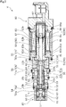
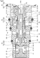
FIG. 2 is a cross-sectional view illustrating a state where a main valve is opened and a CS valve is closed when the capacity control valve according to the embodiment is in a de-energized state. -
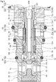
FIG. 3 is a cross-sectional view illustrating a pressure distribution when the main valve and the CS valve are closed in an energized state (e.g., during normal control) of the capacity control valve according to the embodiment. Incidentally, in order to illustrate the pressure distribution, the hatching of the cross section of each member is omitted. -
FIG. 4 is an enlarged cross-sectional view ofFIG. 2 illustrating a state where the main valve is opened and the CS valve is closed when the capacity control valve according to the embodiment is in a de-energized state. -
FIG. 5 is an enlarged cross-sectional view illustrating a state where the main valve and the CS valve are closed when the capacity control valve according to the embodiment is in an energized state (e.g., during normal control). -
FIG. 6 is an enlarged cross-sectional view illustrating a state where the main valve is closed and the CS valve is opened when the capacity control valve according to the embodiment is in an energized state (e.g., maximum energized state). -
FIG. 7 is a graph describing an open and closed state of the main valve and an open and closed state of the CS valve with respect to the stroke position of a main and auxiliary valve body in the capacity control valve according to the embodiment. -
FIG. 8 is an enlarged cross-sectional view illustrating a state where the main valve and the CS valve are closed and a pressure sensitive valve is opened by a predetermined suction pressure when the capacity control valve according to the embodiment is in an energized state (i.e., during startup, during normal control, or the like). -
FIG. 9 is an enlarged cross-sectional view illustrating a state where the main valve is closed, the CS valve is opened, and the pressure sensitive valve is opened by the predetermined suction pressure when the capacity control valve according to the embodiment is in an energized state (e.g., maximum energized state). - A mode for implementing a capacity control valve according to the invention will be described below based on an embodiment.
- A capacity control valve according to an embodiment of the present invention will be described with reference to
FIGS. 1 to 9 . In the following description, right and left sides ofFIG. 2 as viewed from a front side are right and left sides of the capacity control valve. - A capacity control valve V of the invention is assembled into a variable displacement compressor M used in an air conditioning system of an automobile or the like to variably control the pressure of a working fluid (hereinafter, simply referred to as a "fluid") which is a refrigerant, so that the discharge amount of the variable displacement compressor M is controlled to adjust the cooling capacity of the air conditioning system to a desired cooling capacity.
- First, the variable displacement compressor M will be described. As illustrated in
FIG. 1 , the variable displacement compressor M includes acasing 1 including adischarge chamber 2, asuction chamber 3, a control chamber 4, and a plurality ofcylinders 4a. Incidentally, the variable displacement compressor M is provided with a communication passage (unillustrated) through which the control chamber 4 and thesuction chamber 3 communicate directly with each other, and the communication passage is provided with a fixed orifice that balances the pressures of thesuction chamber 3 and the control chamber 4. - In addition, the variable displacement compressor M includes a
rotary shaft 5 that is rotationally driven by an engine (unillustrated) installed outside thecasing 1; aswash plate 6 that is eccentrically coupled to therotary shaft 5 by ahinge mechanism 8 in the control chamber 4; and a plurality ofpistons 7 that are coupled to theswash plate 6 and are reciprocatably fitted into thecylinders 4a. The capacity control valve V, of which the opening and closing is driven by electromagnetic force, appropriately controls the internal pressure of the control chamber 4 while using a suction pressure Ps of thesuction chamber 3 that suctions the fluid, a discharge pressure Pd of thedischarge chamber 2 that discharges the fluid pressurized by thepistons 7, and a control pressure Pc of the control chamber 4 that accommodates theswash plate 6, so that the inclination angle of theswash plate 6 is continuously changed; and thereby, the stroke amounts of thepistons 7 are changed to control the discharge amount of the fluid. Incidentally, for convenience of description, inFIG. 1 , the capacity control valve V that is assembled into the variable displacement compressor M is unillustrated. - Specifically, the higher the control pressure Pc in the control chamber 4, the smaller the inclination angle of the
swash plate 6 with respect to therotary shaft 5, and thus the stroke amounts of thepistons 7 are reduced, and when the control pressure Pc is a certain pressure or higher, theswash plate 6 is substantially perpendicular to therotary shaft 5, namely, is slightly inclined with respect to perpendicularity. In this case, since the stroke amounts of thepistons 7 are minimized and the pressurization of the fluid in thecylinders 4a by thepistons 7 is minimized, the discharge amount of the fluid to thedischarge chamber 2 is reduced, and the cooling capacity of the air conditioning system is minimized. On the other hand, the lower the control pressure Pc in the control chamber 4, the larger the inclination angle of theswash plate 6 with respect to therotary shaft 5, and thus the stroke amounts of thepistons 7 are increased, and when the control pressure Pc is a certain pressure or lower, the inclination angle of theswash plate 6 with respect to therotary shaft 5 is maximized. In this case, since the stroke amounts of thepistons 7 are maximized and the pressurization of the fluid in thecylinders 4a by thepistons 7 is maximized, the discharge amount of the fluid to thedischarge chamber 2 is increased, and the cooling capacity of the air conditioning system is maximized. - As illustrated in
FIG. 2 , in the capacity control valve V assembled into the variable displacement compressor M, a current with which acoil 86 forming asolenoid 80 is to be energized is adjusted to control the opening and closing of amain valve 50, anauxiliary valve 55, and aCS valve 56 in the capacity control valve V, namely, the opening and closing of valves that open and close communication between a control port and a suction port, and the opening and closing of a pressuresensitive valve 54 as an opening and closing valve is controlled by the suction pressure Ps in anintermediate communication passage 57 as a CS communication passage, so that the fluid flowing into the control chamber 4 or flowing out from the control chamber 4 is controlled; and thereby, the control pressure Pc in the control chamber 4 is variably controlled. Incidentally, hollow holes which are formed inside a main andauxiliary valve body 51 as a main valve body and a pressuresensitive valve member 52 are connected to each other, so that theintermediate communication passage 57 penetrates therethrough in an axial direction. - In the present embodiment, the
main valve 50 includes the main andauxiliary valve body 51 and amain valve seat 53a that is formed in an inner diameter portion of a right axial end which is one end of aCS valve body 53, and astep portion 51a that is formed at substantially the center in the axial direction of the main andauxiliary valve body 51 comes into contact with and separates from themain valve seat 53a to open and close themain valve 50. The pressuresensitive valve 54 includes anadapter 70 forming a pressuresensitive body 61 as an opening and closing valve body and a pressuresensitive valve seat 52a as an opening and closing valve seat formed at a left axial end of the pressuresensitive valve member 52, and anouter diameter portion 70a of a right axial end surface of theadapter 70 comes into contact with and separates from the pressuresensitive valve seat 52a to open and close the pressuresensitive valve 54. Theauxiliary valve 55 includes the main andauxiliary valve body 51 and anauxiliary valve seat 82a that is formed in an inner diameter portion of a left axial end surface which is an opening end surface of a fixedcore 82, and a rightaxial end 51b of the main andauxiliary valve body 51 comes into contact with and separates from theauxiliary valve seat 82a to open and close theauxiliary valve 55. TheCS valve 56 includes theCS valve body 53 and aCS valve seat 11a that is formed in an inner diameter portion of a left axial end of asecond valve housing 11 forming a valve housing, and anouter diameter portion 53b of a right axial end that is one end of theCS valve body 53 comes into contact with and separates from theCS valve seat 11a to open and close theCS valve 56. - Next, the structure of the capacity control valve V will be described. As illustrated in
FIG. 2 , the capacity control valve V mainly includes afirst valve housing 10 and thesecond valve housing 11 as the valve housing made of a metallic material or a resin material; the main andauxiliary valve body 51, the pressuresensitive valve member 52, and theCS valve body 53 that are disposed in thefirst valve housing 10 and thesecond valve housing 11 so as to be reciprocatable in the axial direction; the pressuresensitive body 61 that applies rightward axial biasing force to the main andauxiliary valve body 51, the pressuresensitive valve member 52, and theCS valve body 53 according to the suction pressure Ps in theintermediate communication passage 57; and thesolenoid 80 that is connected to thesecond valve housing 11 to apply driving force to the main andauxiliary valve body 51, the pressuresensitive valve member 52, and theCS valve body 53. - As illustrated in
FIG. 2 , thesolenoid 80 mainly includes acasing 81 having an openingportion 81a that is open leftward in the axial direction; the fixedcore 82 that has a substantially cylindrical shape, and is inserted into theopening portion 81a of thecasing 81 from the left in the axial direction to be fixed to an inner diameter side of thecasing 81; adrive rod 83 as a rod which is inserted into the fixedcore 82 to be reciprocatable in the axial direction and of which a leftaxial end portion 83a is inserted into and fixed to the main andauxiliary valve body 51; amovable core 84 to which a rightaxial end portion 83b of thedrive rod 83 is inserted into and fixed; acoil spring 85 that is provided between the fixedcore 82 and themovable core 84 to bias themovable core 84 rightward in the axial direction, namely, a valve opening direction of themain valve 50; and thecoil 86 for excitation that is wound around the outside of the fixedcore 82 via a bobbin. - An inner diameter side of a left axial end of the
casing 81 is recessed rightward in the axial direction to form a recessedportion 81b, and a right axial end portion of thesecond valve housing 11 is inserted into and fixed to the recessedportion 81b in a substantially sealed manner. - The fixed
core 82 is formed of a rigid body made of a magnetic material such as iron or silicon steel, and includes acylindrical portion 82b provided with aninsertion hole 82c into which thedrive rod 83 extending in the axial direction is inserted, and aflange portion 82d that has an annular shape and extends outward in a radial direction from an outer peripheral surface of a left axial end portion of thecylindrical portion 82b. Theauxiliary valve seat 82a is formed in the inner diameter portion of the opening end surface of the fixedcore 82, namely, a left axial end surface of thecylindrical portion 82b. - In addition, the fixed
core 82 is inserted into and fixed to a recessedportion 11d in a substantially sealed manner in a state where a right axial end surface of theflange portion 82d is in contact with a bottom surface of the recessedportion 81b of thecasing 81, and the recessedportion 11d is formed by recessing an inner diameter side of a right axial end of thesecond valve housing 11, which is inserted into and fixed to the recessedportion 81b of thecasing 81, leftward in the axial direction. - The
drive rod 83 is formed in a columnar shape, and the leftaxial end portion 83a of thedrive rod 83 which is inserted into and fixed to the main andauxiliary valve body 51 and the rightaxial end portion 83b of thedrive rod 83 which is inserted into and fixed to themovable core 84 have a plate shape. - In the capacity control valve V, the fixed
core 82 and thesecond valve housing 11 are mounted to thecasing 81, so that a space S1 is formed by a left axial end surface of theflange portion 82d of the fixedcore 82 and an inner peripheral surface of the recessedportion 11d of thesecond valve housing 11. In addition, in the capacity control valve V, acup 87 having a bottomed cylindrical shape is externally fitted to thecylindrical portion 82b of the fixedcore 82 from the right in the axial direction in a substantially sealed manner, so that a space S2 is formed by a right axial end of thecylindrical portion 82b and an inner peripheral surface of thecup 87. In addition, the space S1 communicates with the space S2 via a gap between an inner peripheral surface of theinsertion hole 82c of the fixedcore 82 and an outer peripheral surface of thedrive rod 83, and the spaces S1 and S2 and theinsertion hole 82c of the fixedcore 82 form anaccommodation chamber 90 in which a rear side of the main andauxiliary valve body 51 is accommodated. Incidentally, themovable core 84 disposed in the space S2 is provided with a through-hole 84a extending in the axial direction, and the rightaxial end portion 83b having a plate shape of thedrive rod 83 is inserted into and fixed to the through-hole 84a from the left in the axial direction, so that a plate surface of the rightaxial end portion 83b of thedrive rod 83 and an inner peripheral surface of the through-hole 84a communicate with each other and the fluid always flows between a right axial end of themovable core 84 and a bottom surface of thecup 87. - As illustrate in
FIG. 2 , thefirst valve housing 10 is provided with aPd port 12 as a discharge port communicating with thedischarge chamber 2 of the variable displacement compressor M, aPs port 13 as a suction port communicating with thesuction chamber 3 of the variable displacement compressor M, and asecond Pc port 15 communicating with the control chamber 4 of the variable displacement compressor M. In addition, thesecond valve housing 11 is provided with afirst Pc port 14 as a control port communicating with the control chamber 4 of the variable displacement compressor M. Incidentally, the ports are disposed in order of thefirst Pc port 14, thePs port 13, thePd port 12, and thesecond Pc port 15 from the right side in the axial direction, namely, asolenoid 80 side. - In addition, a right axial end of the
first valve housing 10 is recessed leftward in the axial direction to form a recessedportion 10a, and a left axial end portion of thesecond valve housing 11 is inserted into the recessedportion 10a from the right in the axial direction, so that thesecond valve housing 11 is integrally connected and fixed to thefirst valve housing 10 in a substantially sealed state. In addition, apartition adjustment member 17 is press-fitted into a left axial end portion of thefirst valve housing 10 in a substantially sealed manner, so that thefirst valve housing 10 has a substantially bottomed cylindrical shape. Incidentally, thepartition adjustment member 17 can adjust the installation position in the axial direction of thefirst valve housing 10 to adjust the biasing force of the pressuresensitive body 61. - In addition, a
first valve chamber 20 which communicates with thePd port 12 and in which aPd communication hole 53c penetrating through theCS valve body 53 in the radial direction is disposed, asecond valve chamber 30 which communicates with thePs port 13 and in which a right axial end portion as one end portion of theCS valve body 53 is disposed, and a pressuresensitive chamber 60 as a control fluid supply chamber which communicates with thesecond Pc port 15 and in which the pressuresensitive body 61 is disposed are formed inside thefirst valve housing 10. In addition, athird valve chamber 40 which communicates with thefirst Pc port 14 and in which alarge diameter portion 51c and amedium diameter portion 51d (refer toFIGS. 4 to 6 andFIGS. 8 and9 ) on a right axial end side of the main andauxiliary valve body 51 are disposed is formed inside thesecond valve housing 11. - In addition, the main and
auxiliary valve body 51, the pressuresensitive valve member 52 connected to the main andauxiliary valve body 51, and theCS valve body 53 are disposed in thefirst valve housing 10 and thesecond valve housing 11 so as to be reciprocatable in the axial direction, and guideholes CS valve body 53 is slidable in a substantially sealed state are formed at substantially the center in the axial direction of an inner peripheral surface of thefirst valve housing 10. Incidentally, the inner diameters of the guide holes 10b and 10c of thefirst valve housing 10 are substantially equal. In addition, aguide hole 11b which has a small diameter and against which an outer peripheral surface of the main andauxiliary valve body 51 is slidable in a substantially sealed state is formed in a right axial end portion of an inner peripheral surface of thesecond valve housing 11. Furthermore, theCS valve seat 11a with which theouter diameter portion 53b of the right axial end of theCS valve body 53 can come into contact is formed in an inner diameter portion of a left axial end of thesecond valve housing 11. - Inside the
first valve housing 10, thefirst valve chamber 20 and thesecond valve chamber 30 are partitioned off from each other by the outer peripheral surface of theCS valve body 53 and an inner peripheral surface of theguide hole 10c, and thefirst valve chamber 20 and the pressuresensitive chamber 60 are partitioned off from each other by the outer peripheral surface of theCS valve body 53 and an inner peripheral surface of theguide hole 10b. Incidentally, the inner peripheral surfaces of the guide holes 10b and 10c and the outer peripheral surface of theCS valve body 53 are slightly separated from each other in the radial direction to form very small gaps therebetween, and theCS valve body 53 is smoothly movable relative to thefirst valve housing 10 in the axial direction. - In addition, inside the
second valve housing 11, thethird valve chamber 40 and the accommodation chamber 90 (space S1) are partitioned off from each other by an outer peripheral surface of thelarge diameter portion 51c of the main andauxiliary valve body 51 and the inner peripheral surface of theguide hole 11b. Incidentally, the inner peripheral surface of theguide hole 11b and the outer peripheral surface of the main andauxiliary valve body 51 are slightly separated from each other in the radial direction to form a very small gap therebetween, and the main andauxiliary valve body 51 is smoothly movable relative to thesecond valve housing 11 in the axial direction. - In addition, the
third valve chamber 40 can communicate with thefirst valve chamber 20 or thesecond valve chamber 30 via a gap that is formed in the radial direction between an inner peripheral surface of ashaft hole 11c of the left axial end portion of thesecond valve housing 11 and an outer peripheral surface of themedium diameter portion 51d of the main andauxiliary valve body 51. In more details, as illustrated inFIGS. 2 and4 , when themain valve 50 is opened and theCS valve 56 is closed, thefirst valve chamber 20 and thethird valve chamber 40 communicate with each other, and thethird valve chamber 40 and thesecond valve chamber 30 are isolated from each other. In addition, as illustrated inFIGS. 3 ,5 , and8 , when themain valve 50 and theCS valve 56 are closed, thefirst valve chamber 20 and thethird valve chamber 40 are isolated from each other, and thethird valve chamber 40 and thesecond valve chamber 30 are isolated from each other. In addition, as illustrated inFIGS. 6 and9 , when themain valve 50 is closed and theCS valve 56 is opened, thefirst valve chamber 20 and thethird valve chamber 40 are isolated from each other, and thethird valve chamber 40 and thesecond valve chamber 30 communicate with each other. - In addition, a
Ps communication hole 16 penetrating through thesecond valve housing 11 in the axial direction is provided in thesecond valve housing 11 at a position not to interfere with thethird valve chamber 40 and thefirst Pc port 14, and thesecond valve chamber 30 communicates with theaccommodation chamber 90, namely, the space S1 via thePs communication hole 16. Accordingly, the suction pressure Ps from thePs port 13 is supplied to theaccommodation chamber 90 via thesecond valve chamber 30 and thePs communication hole 16. Incidentally, it is preferable that the flow passage area of thePs communication hole 16 is set to a size such that the suction pressures Ps in thesecond valve chamber 30 and theaccommodation chamber 90 can be substantially equal, for example, a flow passage area which is the half or more of the flow passage area of a first Pc-Ps flow passage (to be described later) or 1 mm or more of diameter of a hole. - As illustrated in
FIGS. 4 to 6 andFIGS. 8 and9 , the main andauxiliary valve body 51 is formed in a substantially stepped cylindrical shape, and includes thelarge diameter portion 51c that is inserted into theguide hole 11b of thesecond valve housing 11, themedium diameter portion 51d that is formed on a left side in the axial direction of thelarge diameter portion 51c to have a smaller diameter than thelarge diameter portion 51c and is inserted into theshaft hole 11c of thesecond valve housing 11, and asmall diameter portion 51e which is formed on a left side in the axial direction of themedium diameter portion 51d to have a smaller diameter than themedium diameter portion 51d and to which theCS valve body 53 formed in a cylindrical shape is externally fitted in a substantially sealed manner. Incidentally, the leftaxial end portion 83a of thedrive rod 83 forming thesolenoid 80 is inserted into and fixed to a right axial end portion of the main andauxiliary valve body 51, namely, a right axial end portion of thelarge diameter portion 51c, and the pressuresensitive valve member 52 as a separate body formed in a substantially cylindrical shape and in a substantially turret shape in a side view is inserted into and fixed to a left axial end portion of the main andauxiliary valve body 51, namely, a left axial end portion of thesmall diameter portion 51e in a substantially sealed manner. Thedrive rod 83, the main andauxiliary valve body 51, and the pressuresensitive valve member 52 are movable together in the axial direction. - In addition, since the left
axial end portion 83a having a plate shape of thedrive rod 83 is inserted into and fixed to the right axial end portion of thelarge diameter portion 51c of the main andauxiliary valve body 51, a plate surface of the leftaxial end portion 83a of thedrive rod 83 and an inner peripheral surface of thelarge diameter portion 51c of the main andauxiliary valve body 51 communicate with each other, and the fluid always flows from the space S1 to theintermediate communication passage 57. - In addition, the
step portion 51a that is formed at substantially the center in the axial direction of the main andauxiliary valve body 51, namely, a left axial end of themedium diameter portion 51d is formed in a tapered shape that is tapered toward the left in the axial direction where thesmall diameter portion 51e is formed, and comes into contact with and separates from themain valve seat 53a that is formed in the inner diameter portion of the right axial end of theCS valve body 53. - In addition, the main and
auxiliary valve body 51 is slidable in a state where a gap between an outer peripheral surface of the left axial end portion of thesmall diameter portion 51e and an inner peripheral surface of a left axial end portion of theCS valve body 53 is substantially sealed, and a gap that is formed in the radial direction formed between the main andauxiliary valve body 51 and theCS valve body 53 is partitioned off from the pressuresensitive chamber 60. Incidentally, the outer peripheral surface of the left axial end portion of thesmall diameter portion 51e of the main andauxiliary valve body 51 and the inner peripheral surface of the left axial end portion of theCS valve body 53 are slightly separated from each other in the radial direction to form a very small gap, and the main andauxiliary valve body 51 is smoothly movable relative to theCS valve body 53 in the axial direction. - In addition, since the
small diameter portion 51e of the main andauxiliary valve body 51 is formed in a constricted shape where an outer peripheral surface is recessed toward an inner diameter side from a right axial end portion to substantially the center in the axial direction, and theCS valve body 53 externally fitted to thesmall diameter portion 51e is formed in a constricted shape where an inner peripheral surface at substantially the center in the axial direction is recessed toward an outer diameter side, when themain valve 50 is opened, a Pd-Pc flow passage (illustrated by a solid arrow inFIG. 4 ) with a large flow passage area from thePd port 12 to thefirst Pc port 14 can be secured. - As illustrated in
FIGS. 4 to 6 andFIGS. 8 and9 , acoil spring 58 as biasing means is externally fitted to the left axial end portion of thesmall diameter portion 51e of the main andauxiliary valve body 51. A left axial end of thecoil spring 58 is in contact with a right surface in the axial direction of aflange portion 52b of the pressuresensitive valve member 52, and a right axial end of thecoil spring 58 is in contact with a left axial end as the other end of theCS valve body 53. Incidentally, thecoil spring 58 applies biasing force toward the right in the axial direction, namely, in a valve closing direction of theCS valve 56 such that theouter diameter portion 53b of the right axial end which is one end of theCS valve body 53 comes into contact with theCS valve seat 11a formed in the inner diameter portion of the left axial end of thesecond valve housing 11. In addition, thecoil spring 58 is set to have a smaller spring constant than acoil spring 63 provided in the pressuresensitive body 61. - As illustrated in
FIGS. 2 to 6 andFIGS. 8 and9 , the pressuresensitive body 61 mainly includes abellows core 62 where thecoil spring 63 is built in, and theadapter 70 which has a disk shape and is provided at a right axial end of thebellows core 62, and a left axial end of thebellows core 62 is fixed to thepartition adjustment member 17. - In addition, the pressure
sensitive body 61 is disposed in the pressuresensitive chamber 60, and theouter diameter portion 70a of the right axial end surface of theadapter 70 is seated on the pressuresensitive valve seat 52a of the left axial end of the pressuresensitive valve member 52 by the biasing force of thecoil spring 63 and thebellows core 62. Namely, the leftward axial driving force of thesolenoid 80 is applied to the pressuresensitive body 61 via thedrive rod 83, the main andauxiliary valve body 51, and the pressuresensitive valve member 52, and thedrive rod 83, the main andauxiliary valve body 51, and the pressuresensitive valve member 52 receive a rightward axial reaction force from the pressuresensitive body 61. - Here, a pressure distribution in the capacity control valve V will be described with reference to
FIG. 3 . Incidentally,FIG. 3 illustrates a state where themain valve 50, theCS valve 56, and the pressuresensitive valve 54 are closed and theauxiliary valve 55 is opened when the capacity control valve V is in an energized state (e.g., during normal control). As illustrated inFIG. 3 , the control pressure Pc introduced from thefirst Pc port 14 is distributed from thethird valve chamber 40 to a right side in the axial direction of themain valve 50 closed and an inner diameter side of theCS valve 56 closed, via the gap that is formed in the radial direction between the inner peripheral surface of theshaft hole 11c of thesecond valve housing 11 and the outer peripheral surface of themedium diameter portion 51d of the main andauxiliary valve body 51. In addition, the suction pressure Ps introduced from thePs port 13 is distributed to an outer diameter side of theCS valve 56 closed in thesecond valve chamber 30, and is introduced from thesecond valve chamber 30 to theaccommodation chamber 90 via thePs communication hole 16 of thesecond valve housing 11 to be distributed to a Pspressure receiving surface 70b, which is formed in the right axial end surface of theadapter 70 of the pressuresensitive body 61, via theintermediate communication passage 57 that is formed inside the main andauxiliary valve body 51 and the pressuresensitive valve member 52. In addition, the discharge pressure Pd introduced from thePd port 12 is distributed from thefirst valve chamber 20 to a left side in the axial direction of themain valve 50 closed, via thePd communication hole 53c of theCS valve body 53 and the gap that is formed in the radial direction between the inner peripheral surface of theCS valve body 53 and the outer peripheral surface of the main andauxiliary valve body 51. In addition, the control pressure Pc introduced from thesecond Pc port 15 is distributed in the pressuresensitive chamber 60. Incidentally, as illustrated inFIG. 3 , since the suction pressures Ps are applied from both ends in the axial direction to themovable core 84, thedrive rod 83, the main andauxiliary valve body 51, and the pressuresensitive valve member 52 that are moved together by the driving force of thesolenoid 80, the valve body can be precisely controlled according to a current applied to thesolenoid 80 in a state where the influence of the pressures is suppressed. - Next, an operation of the capacity control valve V, mainly, an opening and closing operation of the
main valve 50 and theCS valve 56 will be described. - First, a de-energized state of the capacity control valve V will be described. As illustrated in
FIGS. 2 and4 , when the capacity control valve V is in a de-energized state, since themovable core 84 is pressed rightward in the axial direction by the biasing force of thecoil spring 85 forming thesolenoid 80 or the biasing force of thecoil spring 63 and thebellows core 62, thedrive rod 83, the main andauxiliary valve body 51, and the pressuresensitive valve member 52 move rightward in the axial direction, so that the rightaxial end 51b of the main andauxiliary valve body 51 is seated on theauxiliary valve seat 82a of the fixedcore 82 to close theauxiliary valve 55, and thestep portion 51a of the main andauxiliary valve body 51 separates from themain valve seat 53a, which is formed in the inner diameter portion of the right axial end of theCS valve body 53, to open themain valve 50. - In addition, when the capacity control valve V is in a de-energized state, the
step portion 51a of the main andauxiliary valve body 51 separates from themain valve seat 53a of theCS valve body 53, and the biasing force Fsp2 of thecoil spring 58 is applied to press theCS valve body 53 rightward in the axial direction, namely, in the valve closing direction of theCS valve 56, so that theouter diameter portion 53b of the right axial end of theCS valve body 53 is seated on theCS valve seat 11a, which is formed in the inner diameter portion of the left axial end of thesecond valve housing 11, to close theCS valve 56. - At this time, the biasing force Fsp2 of the
coil spring 58 is applied leftward in the axial direction to the main andauxiliary valve body 51 via theflange portion 52b of the pressuresensitive valve member 52, and the biasing force Fsp1 of thecoil spring 85 and the biasing force Fbel of the pressure sensitive body 61 (namely, the biasing force of thebellows core 62 and the coil spring 63) are applied rightward in the axial direction to the main andauxiliary valve body 51 via thedrive rod 83 forming thesolenoid 80 and the pressuresensitive valve member 52, respectively (namely, with a rightward direction being positive,force F rod1 = Fsp1 + Fbel - Fsp2 is applied to the main and auxiliary valve body 51). Incidentally, the influence of the pressures is omitted due to being small. - Next, an energized state of the capacity control valve V will be described. As illustrated in
FIG. 5 , when the capacity control valve V is in an energized state (namely, during normal control, so-called duty control), ifelectromagnetic force F sol1 generated by the application of a current to thesolenoid 80 is greater than the force Frod1 (i.e.,F sol1 > Frod1), since themovable core 84 is pulled toward a fixedcore 82 side, namely, leftward in the axial direction, thedrive rod 83 fixed to themovable core 84, the main andauxiliary valve body 51, and the pressuresensitive valve member 52 move together leftward in the axial direction, and the pressuresensitive body 61 is pressed leftward in the axial direction to be contracted, so that the rightaxial end 51b of the main andauxiliary valve body 51 separates from theauxiliary valve seat 82a of the fixedcore 82 to open theauxiliary valve 55, and thestep portion 51a of the main andauxiliary valve body 51 is seated on themain valve seat 53a of theCS valve body 53 to close themain valve 50. - At this time, the
electromagnetic force F sol1 toward the left in the axial direction, and the biasing force Fsp1 of thecoil spring 85 and the biasing force Fbel of the pressuresensitive body 61 toward the right in the axial direction are applied to the main and auxiliary valve body 51 (namely, with the rightward direction being positive,force F rod2 = Fsp1 + Fbel -F sol1 is applied to the main and auxiliary valve body 51). Incidentally, the biasing force Fsp2 of thecoil spring 58 is applied leftward in the axial direction to the main andauxiliary valve body 51 until thestep portion 51a of the main andauxiliary valve body 51 is seated on themain valve seat 53a of theCS valve body 53, and at the moment when thestep portion 51a of the main andauxiliary valve body 51 is seated on themain valve seat 53a of theCS valve body 53, theCS valve body 53 and thecoil spring 58 are held between thestep portion 51a of the main andauxiliary valve body 51 and theflange portion 52b of the pressuresensitive valve member 52, which moves together with the main andauxiliary valve body 51, and thus the biasing force Fsp2 is not applied to the main andauxiliary valve body 51. - During normal control of the capacity control valve V, when the opening degree or opening time of the
main valve 50 is adjusted to control the flow rate of the fluid from thePd port 12 to thefirst Pc port 14, the current value is controlled such that the electromagnetic force (Fsol1) generated by the application of a current to thesolenoid 80 is greater than the force Frod1 (i.e.,F sol1 > Frod1) and is less than the force Frod2 (i.e.,F sol1 < Frod2); and thereby the opening and closing of themain valve 50 can be controlled in a state where the closing of theCS valve 56 is maintained. - In addition, when the variable displacement compressor M is driven at the maximum capacity, as illustrated in
FIG. 6 , the capacity control valve V is brought into a maximum energized state (namely, energized state at the maximum duty during normal control) to causeelectromagnetic force F sol2 generated by the application of the maximum current to thesolenoid 80 to be greater than the force Frod2 (i.e.,F sol2 > Frod2), so that the main andauxiliary valve body 51 fixed to thedrive rod 83 pushes theCS valve body 53 leftward in the axial direction and the main andauxiliary valve body 51 moves together with theCS valve body 53 leftward in the axial direction; and thereby, theouter diameter portion 53b of the right axial end of theCS valve body 53 separates from theCS valve seat 11a of thesecond valve housing 11 to open theCS valve 56. Accordingly, as thedrive rod 83 moves while a closed state of themain valve 50 is maintained, the main andauxiliary valve body 51 moves together with theCS valve body 53 to open theCS valve 56, and the first Pc-Ps flow passage (illustrated by a solid arrow inFIG. 6 ) through which thefirst Pc port 14 and thePs port 13 communicate with each other is formed, namely, the control chamber 4 and thesuction chamber 3 communicate with each other, so that the control pressure Pc can be quickly lowered to maintain the control pressure Pc and the suction pressure Ps at equal pressure. Therefore, the capacity control valve V having a high compression efficiency can be provided. In addition, even during startup of the variable displacement compressor M, the capacity control valve V is brought into a maximum energized state to open theCS valve 56 and to allow thefirst Pc port 14 and thePs port 13 to communicate with each other. Therefore, the capacity control valve V having a good fluid discharge function during startup can be provided. - Next, an open and closed state of the
main valve 50 and an open and closed state of theCS valve 56 with respect to the stroke position of the main andauxiliary valve body 51 will be described with reference toFIG. 7 . Incidentally, the horizontal axis ofFIG. 7 represents the stroke position to which the main andauxiliary valve body 51 moves according to a current applied to thesolenoid 80. As illustrated inFIG. 7 , when the stroke position of the main andauxiliary valve body 51 is 0, which corresponds to when thesolenoid 80 is de-energized, theCS valve 56 is closed and the opening area of themain valve 50 is maximized. The opening area of the main valve 50 (i.e., Pd-Pc flow passage) is linearly reduced according to the stroke position of the main andauxiliary valve body 51, which is dependent on a current applied to thesolenoid 80. At this time, the closed state of theCS valve 56 is maintained. When the stroke position of the main andauxiliary valve body 51 reaches a point P, themain valve 50 and theCS valve 56 are closed. Then, when the stroke position of the main andauxiliary valve body 51 passes the point P, the closed state of themain valve 50 is maintained, and the opening area of the CS valve 56 (i.e., first Pc-Ps flow passage) is linearly increased according to the stroke position of the main andauxiliary valve body 51. In such a manner, the switching of opening and closing of themain valve 50 and theCS valve 56 can be performed depending on the stroke position of the main andauxiliary valve body 51 with respect to the point P, and thus the controllability is improved. - In addition, as illustrated in
FIGS. 8 and9 , during startup or normal control of the capacity control valve V, when the force based on the suction pressure Ps, namely, the suction pressure Ps in theintermediate communication passage 57 which is applied to the Pspressure receiving surface 70b of theadapter 70 of the pressuresensitive body 61 is greater than the biasing force of thebellows core 62 and thecoil spring 63 that form the pressuresensitive body 61, due to contraction of the pressuresensitive body 61, theouter diameter portion 70a of the right axial end surface of theadapter 70 separates from the pressuresensitive valve seat 52a of the pressuresensitive valve member 52 to open the pressuresensitive valve 54, and a second Pc-Ps flow passage (illustrated by solid arrows inFIGS. 8 and9 ) through which thesecond Pc port 15 and thePs port 13 communicate with each other is formed, namely, the control chamber 4 and thesuction chamber 3 communicate with each other via theintermediate communication passage 57, so that the control pressure Pc can be quickly lowered to maintain the control pressure Pc and the suction pressure Ps at equal pressure; and thereby, the capacity control valve V having a stable fluid discharge function and compression performance during startup can be provided. Particularly, as illustrated inFIG. 8 , since the capacity control valve V is brought into a maximum energized state to open theCS valve 56, and the pressuresensitive valve 54 is opened by a predetermined suction pressure Ps, two Pc-Ps flow passages can communicate with each other, and thus the fluid discharge function during startup can be further improved. - In addition, during startup, normal control, or the like, since the main and
auxiliary valve body 51 moves leftward in the axial direction to open theauxiliary valve 55, when the pressuresensitive valve 54 is opened by the predetermined suction pressure Ps, theintermediate communication passage 57 becomes effective to allow the pressuresensitive chamber 60 and thePs port 13 to communicate with each other. - In addition, since the
CS valve body 53 is externally fitted to the main andauxiliary valve body 51, and themain valve seat 53a is formed in the inner diameter portion of theCS valve body 53, the capacity control valve V including theCS valve 56 can be configured more simply and compactly, and the main andauxiliary valve body 51 can move together with theCS valve body 53 while a closed state of themain valve 50 is reliably maintained. - In addition, since the
main valve seat 53a forming themain valve 50 is formed in the inner diameter portion of the right axial end that is one end of theCS valve body 53, and theCS valve 56 including theouter diameter portion 53b and theCS valve seat 11a is formed on the outer diameter side thereof, switching between the Pd-Pc flow passage and the first Pc-Ps flow passage by the opening and closing of themain valve 50 and theCS valve 56 can be smoothly performed, and thus the responsiveness is good. - In addition, since the
CS valve body 53 is biased rightward in the axial direction, namely, in the valve closing direction of theCS valve 56 by thecoil spring 58, when the current value is decreased, theCS valve body 53 can reliably move to a closed valve position, and the capacity control valve V can immediately return from the maximum energized state at the maximum duty to a state less energized than the maximum energized state (duty control). - In addition, as illustrated in
FIG. 3 , since the control pressure Pc supplied from thefirst Pc port 14 to thethird valve chamber 40 is introduced to a right axial end side that is one end side of theCS valve body 53, and the control pressure Pc supplied from thesecond Pc port 15 to the pressuresensitive chamber 60 is introduced to a left axial end side that is the other end side of theCS valve body 53, the control pressures Pc can be applied to theCS valve body 53 from both ends in the axial direction, and theCS valve body 53 can move together with the main andauxiliary valve body 51 in a state where the influence of the pressures is suppressed; and thereby, the valve body can be precisely controlled according to a current applied to thesolenoid 80. Furthermore, since an effective area A of the left axial end portion that is the other end portion of theCS valve body 53 is set to be equal to an effective area B of the right axial end portion that is one end portion of the CS valve body 53 (A = B), the control pressures Pc applied to both ends in the axial direction of theCS valve body 53 are cancelled out, and thus the valve body can be more precisely controlled. - The embodiment of the invention has been described above with reference to the drawings; however, the specific configuration is not limited to the embodiment, and the invention also includes changes or additions that are made without departing from the concept of the invention.
- For example, the above embodiment has described a mode where the effective areas A and B of both ends in the axial direction of the
CS valve body 53 are set to be equal (A = B) so that the control pressures Pc applied to both ends in the axial direction of theCS valve body 53 are cancelled out; however, the invention is not limited to the configuration, for example, the effective area A of the left axial end of the CS valve body may be set to be larger than the effective area B of the right axial end of the CS valve body (i.e., A > B), and thus when themain valve 50 is closed, the control pressure Pc is applied rightward in the axial direction, namely, in the valve opening direction to adjust the driving force of thesolenoid 80; and thereby, control characteristics of the main andauxiliary valve body 51 are changed. Incidentally, the spring constant of thecoil spring 58 may be changed to change the control characteristics of the main andauxiliary valve body 51. - In addition, the disposition in the axial direction of the
CS valve body 53 with respect to the main andauxiliary valve body 51, the forming position in the axial direction of theCS valve seat 11a in thesecond valve housing 11, or the dimensions, shape, or the like of theCS valve body 53 may be changed to appropriately adjust the opening and closing timing of themain valve 50 and theCS valve 56 depending on the stroke position of the main andauxiliary valve body 51 which is based on the driving force of thesolenoid 80. - In addition, the above embodiment has described an example where the
CS valve 56 is configured such that theCS valve body 53 that moves relative to the main andauxiliary valve body 51 comes into contact with and separates from theCS valve seat 11a of thesecond valve housing 11; however, other configurations may be adopted, and for example, the CS valve may have a spool valve structure. - In addition, a groove extending in a circumferential direction may be formed in at least one of the outer peripheral surfaces of the main and
auxiliary valve body 51 and theCS valve body 53 and the inner peripheral surfaces of the guide holes 10b and 10c of thefirst valve housing 10 and theguide hole 11b of thesecond valve housing 11, and accordingly, the sealability of sliding portions between the main andauxiliary valve body 51 and thefirst valve housing 10 and between theCS valve body 53 and thesecond valve housing 11 is improved by the labyrinth effect of the groove, and thus leakage of the fluid can be suppressed. - In addition, an example where the main and
auxiliary valve body 51 and the pressuresensitive valve member 52 are formed as separate bodies has been described; however, both may be integrally formed. - In addition, the communication passage through which the control chamber 4 and the
suction chamber 3 of the variable displacement compressor M communicate directly with each other, and the fixed orifice may not be provided. - In addition, in the above embodiment, the
auxiliary valve 55 may not be provided, and the right axial end of the main andauxiliary valve body 51 may serve as a support member receiving an axial load, and does not necessarily require a sealing function. - In addition, the
first valve housing 10 and thesecond valve housing 11 that form the valve housing may be integrally formed. - In addition, instead that the coil spring is used inside the pressure
sensitive body 61, thebellows core 62 may have biasing force. -
- 1 Casing
- 2 Discharge chamber
- 3 Suction chamber
- 4 Control chamber
- 10 First valve housing (valve housing)
- 11 Second valve housing (valve housing)
- 11a CS valve seat
- 12 Pd port (discharge port)
- 13 Ps port (suction port)
- 14 First Pc port (control port)
- 15 Second Pc port
- 16 Ps communication hole
- 20 First valve chamber
- 30 Second valve chamber
- 40 Third valve chamber
- 50 Main valve
- 51 Main and auxiliary valve body (main valve body)
- 51a Step portion
- 51b Right axial end
- 52 Pressure sensitive valve member
- 52a Pressure sensitive valve seat (opening and closing valve seat)
- 53 CS valve body
- 53a Main valve seat
- 53b Outer diameter portion
- 54 Pressure sensitive valve (opening and closing valve)
- 55 Auxiliary valve
- 56 CS valve
- 57 Intermediate communication passage (CS communication passage)
- 58 Coil spring (biasing means)
- 60 Pressure sensitive chamber (control fluid supply chamber)
- 61 Pressure sensitive body (opening and closing valve body)
- 62 Bellows core
- 63 Coil spring
- 70 Adapter
- 70a Outer diameter portion
- 70b Ps pressure receiving surface
- 80 Solenoid
- 82 Fixed core
- 82a Auxiliary valve seat
- 83 Drive rod (rod)
- 84 Movable core
- 85 Coil spring
- 90 Accommodation chamber
- A, B Effective area of CS valve body
- Pc Control pressure
- Pd Discharge pressure
- Ps Suction pressure
- S1, S2 Space
- V Capacity control valve
Claims (7)
- A capacity control valve comprising:a valve housing provided with a discharge port through which a discharge fluid at a discharge pressure passes, a suction port through which a suction fluid at a suction pressure passes, and a control port through which a control fluid at a control pressure passes;a rod driven by a solenoid;a main valve that includes a main valve seat and a main valve body to open and close a communication between the discharge port and the control port in accordance with a movement of the rod moves;an opening and closing valve including an opening and closing valve seat and an opening and closing valve body biased in a valve closing direction, the opening and closing valve being configured to open and close a CS communication passage communicating with the suction port and a control fluid supply chamber formed in the valve housing, the control fluid being supplied to the control fluid supply chamber; anda CS valve that includes a CS valve seat and a CS valve body to open and close a communication between the control port and the suction port, the CS valve body being disposed so as to be movable relative to the main valve body,wherein the main valve body and the CS valve body move together as the rod moves in a closed state of the main valve.
- The capacity control valve according to claim 1,
wherein the CS valve body is externally fitted to the main valve body, and the main valve seat is formed in an inner diameter portion of the CS valve body. - The capacity control valve according to claim 2,
wherein the main valve seat is formed at one end of the CS valve body, and the CS valve seat is formed on an outer diameter side of the main valve seat. - The capacity control valve according to any one of claims 1 to 3,
wherein the CS valve body is biased in a valve closing direction of the CS valve by biasing means. - The capacity control valve according to any one of claims 1 to 4,
wherein the control fluid from the control port is introduced to one end side of the CS valve body, and the control fluid supplied to the control fluid supply chamber is introduced to the other end side of the CS valve body. - The capacity control valve according to claim 5,
wherein effective areas of both ends of the CS valve body are equal to each other. - The capacity control valve according to any one of claims 1 to 6,
wherein the main valve body forms an auxiliary valve that opens and closes a communication between the CS communication passage and the suction port.
Applications Claiming Priority (2)
| Application Number | Priority Date | Filing Date | Title |
|---|---|---|---|
| JP2018227597 | 2018-12-04 | ||
| PCT/JP2019/047192 WO2020116435A1 (en) | 2018-12-04 | 2019-12-03 | Displacement control valve |
Publications (3)
| Publication Number | Publication Date |
|---|---|
| EP3892856A1 true EP3892856A1 (en) | 2021-10-13 |
| EP3892856A4 EP3892856A4 (en) | 2022-07-06 |
| EP3892856B1 EP3892856B1 (en) | 2024-03-27 |
Family
ID=70973903
Family Applications (1)
| Application Number | Title | Priority Date | Filing Date |
|---|---|---|---|
| EP19894059.5A Active EP3892856B1 (en) | 2018-12-04 | 2019-12-03 | Capacity control valve |
Country Status (6)
| Country | Link |
|---|---|
| US (1) | US11473684B2 (en) |
| EP (1) | EP3892856B1 (en) |
| JP (1) | JP7326329B2 (en) |
| KR (1) | KR102596905B1 (en) |
| CN (1) | CN113167264B (en) |
| WO (1) | WO2020116435A1 (en) |
Families Citing this family (4)
| Publication number | Priority date | Publication date | Assignee | Title |
|---|---|---|---|---|
| US11994120B2 (en) | 2018-07-12 | 2024-05-28 | Eagle Industry Co., Ltd. | Capacity control valve |
| CN112513460B (en) | 2018-08-08 | 2023-04-28 | 伊格尔工业股份有限公司 | Capacity control valve |
| US12292130B2 (en) * | 2019-01-21 | 2025-05-06 | Eagle Industry Co., Ltd. | Capacity control valve |
| CN115427684B (en) | 2020-04-23 | 2025-08-05 | 伊格尔工业股份有限公司 | Capacity control valve |
Family Cites Families (64)
| Publication number | Priority date | Publication date | Assignee | Title |
|---|---|---|---|---|
| JPS5862775A (en) | 1981-10-08 | 1983-04-14 | Sankyo Seiki Mfg Co Ltd | Processor for card with magnetic stripe |
| JP3082417B2 (en) * | 1991-09-18 | 2000-08-28 | 株式会社豊田自動織機製作所 | Variable displacement compressor |
| JP3089816B2 (en) | 1992-04-28 | 2000-09-18 | 株式会社豊田自動織機製作所 | Swash plate type variable displacement compressor |
| JPH06200875A (en) | 1993-01-08 | 1994-07-19 | Toyota Autom Loom Works Ltd | Rocking swash plate type variable displacement compressor |
| JP3242496B2 (en) | 1993-07-06 | 2001-12-25 | 株式会社豊田自動織機 | External switching type displacement control valve for variable displacement compressor |
| JPH09144929A (en) | 1995-11-16 | 1997-06-03 | Tosok Corp | Solenoid valve |
| KR100215157B1 (en) * | 1996-06-19 | 1999-08-16 | 이소가이 지세이 | Variable displacement compressor and its attachment method |
| US6010312A (en) | 1996-07-31 | 2000-01-04 | Kabushiki Kaisha Toyoda Jidoshokki Seiksakusho | Control valve unit with independently operable valve mechanisms for variable displacement compressor |
| JP3583951B2 (en) | 1999-06-07 | 2004-11-04 | 株式会社豊田自動織機 | Capacity control valve |
| JP2001073939A (en) | 1999-08-31 | 2001-03-21 | Toyota Autom Loom Works Ltd | Control valve for variable displacement compressor and variable displacement compressor |
| JP2001099060A (en) | 1999-10-04 | 2001-04-10 | Fuji Koki Corp | Control valve for variable displacement compressor |
| JP3991556B2 (en) * | 1999-10-04 | 2007-10-17 | 株式会社豊田自動織機 | Control valve for variable capacity compressor |
| JP2001132632A (en) | 1999-11-10 | 2001-05-18 | Toyota Autom Loom Works Ltd | Control valve of variable displacement compressor |
| JP3942851B2 (en) | 2001-07-31 | 2007-07-11 | 株式会社テージーケー | Capacity control valve |
| JP4242624B2 (en) | 2002-09-26 | 2009-03-25 | イーグル工業株式会社 | Capacity control valve and control method thereof |
| JP4316955B2 (en) | 2003-08-11 | 2009-08-19 | イーグル工業株式会社 | Capacity control valve |
| JP2006097665A (en) | 2004-06-28 | 2006-04-13 | Toyota Industries Corp | Capacity control valve in variable displacement compressor |
| JP4431462B2 (en) | 2004-08-10 | 2010-03-17 | 株式会社鷺宮製作所 | Swash plate type variable capacity compressor and electromagnetic control valve |
| CN100516516C (en) | 2005-02-24 | 2009-07-22 | 株式会社丰田自动织机 | Capacity control valve |
| JP2006307828A (en) | 2005-03-31 | 2006-11-09 | Tgk Co Ltd | Control valve for variable displacement compressor |
| CN101410620B (en) | 2006-03-15 | 2011-03-23 | 伊格尔工业股份有限公司 | Capacity control valve |
| JP2007247512A (en) | 2006-03-15 | 2007-09-27 | Toyota Industries Corp | Capacity control valve in variable capacity type compressor |
| JP2008014269A (en) | 2006-07-07 | 2008-01-24 | Toyota Industries Corp | Displacement control valve for variable displacement compressor |
| JP2008202572A (en) | 2007-02-22 | 2008-09-04 | Toyota Industries Corp | Capacity control valve of variable displacement compressor |
| JP4861956B2 (en) | 2007-10-24 | 2012-01-25 | 株式会社豊田自動織機 | Capacity control valve in variable capacity compressor |
| JP2011032916A (en) * | 2009-07-31 | 2011-02-17 | Tgk Co Ltd | Control valve |
| KR101099121B1 (en) | 2009-08-19 | 2011-12-27 | 주식회사 두원전자 | Vacuum bellows assembly manufacturing method |
| KR101319565B1 (en) | 2010-03-16 | 2013-10-23 | 이구루코교 가부시기가이샤 | Volume control valve |
| US8757988B2 (en) | 2010-04-29 | 2014-06-24 | Eagle Industry Co., Ltd. | Capacity control valve |
| JP5665722B2 (en) | 2011-11-17 | 2015-02-04 | 株式会社豊田自動織機 | Capacity control valve |
| KR101322404B1 (en) * | 2012-01-19 | 2013-10-28 | (주)대정고분자산업 | Electric control valve for variable displacement compressor |
| US20150068628A1 (en) | 2012-05-24 | 2015-03-12 | Eagle Industry Co., Ltd. | Capacity control valve |
| JP6064132B2 (en) | 2012-10-09 | 2017-01-25 | 株式会社テージーケー | Compound valve |
| US9714646B2 (en) | 2012-12-12 | 2017-07-25 | Eagle Industry Co., Ltd. | Capacity control valve |
| JP6020130B2 (en) | 2012-12-19 | 2016-11-02 | 株式会社豊田自動織機 | Variable capacity swash plate compressor |
| EP2952741B1 (en) | 2013-01-31 | 2019-03-13 | Eagle Industry Co., Ltd. | Variable capacity compressor |
| JP6103586B2 (en) | 2013-03-27 | 2017-03-29 | 株式会社テージーケー | Control valve for variable capacity compressor |
| JP6149239B2 (en) | 2013-06-28 | 2017-06-21 | 株式会社テージーケー | Control valve for variable capacity compressor |
| JP6206274B2 (en) | 2014-03-19 | 2017-10-04 | 株式会社豊田自動織機 | Capacity control valve |
| EP3239570B1 (en) | 2014-12-25 | 2020-05-13 | Eagle Industry Co., Ltd. | Volume control valve |
| JP2016125376A (en) * | 2014-12-26 | 2016-07-11 | 株式会社テージーケー | Control valve for variable displacement compressor |
| JP6500183B2 (en) | 2015-04-02 | 2019-04-17 | 株式会社テージーケー | Control valve for variable displacement compressor |
| US20170028462A1 (en) | 2015-07-28 | 2017-02-02 | Primetals Technologies USA LLC | Simple copper tube design for continuous casting process with enhanced rigidity |
| WO2017057160A1 (en) * | 2015-09-29 | 2017-04-06 | 株式会社ヴァレオジャパン | Variable displacement compressor control valve |
| JP6383720B2 (en) * | 2015-12-16 | 2018-08-29 | 株式会社不二工機 | Control valve for variable displacement compressor |
| JP6663227B2 (en) | 2016-01-19 | 2020-03-11 | サンデン・オートモーティブコンポーネント株式会社 | Displacement control valve for variable displacement compressor |
| JP6500184B2 (en) * | 2016-02-25 | 2019-04-17 | 株式会社テージーケー | Control valve for variable displacement compressor |
| JP6500186B2 (en) | 2016-02-25 | 2019-04-17 | 株式会社テージーケー | Control valve for variable displacement compressor |
| WO2017159553A1 (en) | 2016-03-17 | 2017-09-21 | イーグル工業株式会社 | Capacity control valve |
| JP6714274B2 (en) | 2016-06-13 | 2020-06-24 | 株式会社テージーケー | Control valve for variable capacity compressor |
| CN108071824B (en) | 2016-06-13 | 2021-08-10 | 株式会社Tgk | Control valve for variable displacement compressor |
| JP2018021646A (en) | 2016-08-05 | 2018-02-08 | 株式会社鷺宮製作所 | Pressure sensitive control valve |
| JP2018040385A (en) | 2016-09-05 | 2018-03-15 | 株式会社テージーケー | solenoid valve |
| EP3564528B1 (en) | 2016-12-28 | 2022-08-03 | Eagle Industry Co., Ltd. | Capacity control valve |
| JP2018145877A (en) | 2017-03-06 | 2018-09-20 | 株式会社豊田自動織機 | Variable capacity-type swash plate compressor |
| JP6924476B2 (en) | 2017-04-07 | 2021-08-25 | 株式会社テージーケー | Control valve for variable displacement compressor |
| JP6997536B2 (en) * | 2017-05-09 | 2022-01-17 | サンデン・オートモーティブコンポーネント株式会社 | Solenoid control valve and variable displacement compressor equipped with it |
| JP2019002384A (en) | 2017-06-19 | 2019-01-10 | サンデン・オートモーティブコンポーネント株式会社 | Variable displacement compressor |
| US11512786B2 (en) | 2017-11-30 | 2022-11-29 | Eagle Industry Co., Ltd. | Capacity control valve and control method for capacity control valve |
| JP7167067B2 (en) | 2018-01-26 | 2022-11-08 | イーグル工業株式会社 | capacity control valve |
| EP3760864B1 (en) * | 2018-02-27 | 2022-11-16 | Eagle Industry Co., Ltd. | Capacity control valve |
| US11873805B2 (en) * | 2018-08-08 | 2024-01-16 | Eagle Industry Co., Ltd. | Capacity control valve |
| US11053933B2 (en) | 2018-12-13 | 2021-07-06 | Eagle Industry Co., Ltd. | Displacement control valve |
| US11300219B2 (en) * | 2020-07-28 | 2022-04-12 | Mahle International Gmbh | Variable-capacity compressor control valve |
-
2019
- 2019-12-03 EP EP19894059.5A patent/EP3892856B1/en active Active
- 2019-12-03 WO PCT/JP2019/047192 patent/WO2020116435A1/en not_active Ceased
- 2019-12-03 JP JP2020559213A patent/JP7326329B2/en active Active
- 2019-12-03 US US17/299,285 patent/US11473684B2/en active Active
- 2019-12-03 KR KR1020217018244A patent/KR102596905B1/en active Active
- 2019-12-03 CN CN201980079538.7A patent/CN113167264B/en active Active
Also Published As
| Publication number | Publication date |
|---|---|
| EP3892856B1 (en) | 2024-03-27 |
| WO2020116435A1 (en) | 2020-06-11 |
| US20220057005A1 (en) | 2022-02-24 |
| KR20210091269A (en) | 2021-07-21 |
| CN113167264B (en) | 2023-02-28 |
| JPWO2020116435A1 (en) | 2021-10-21 |
| JP7326329B2 (en) | 2023-08-15 |
| US11473684B2 (en) | 2022-10-18 |
| CN113167264A (en) | 2021-07-23 |
| KR102596905B1 (en) | 2023-11-01 |
| EP3892856A4 (en) | 2022-07-06 |
Similar Documents
| Publication | Publication Date | Title |
|---|---|---|
| US11156301B2 (en) | Capacity control valve | |
| US11635152B2 (en) | Capacity control valve | |
| WO2020013169A1 (en) | Capacity control valve | |
| EP3892856B1 (en) | Capacity control valve | |
| WO2020032087A1 (en) | Capacity control valve | |
| JP7162995B2 (en) | capacity control valve | |
| JP7467427B2 (en) | Capacity Control Valve | |
| JP7504989B2 (en) | Capacity Control Valve | |
| US12025237B2 (en) | Capacity control valve | |
| JP7438643B2 (en) | capacity control valve | |
| US11994120B2 (en) | Capacity control valve | |
| EP3892855B1 (en) | Capacity control valve | |
| US11378194B2 (en) | Capacity control valve | |
| WO2019159999A1 (en) | Capacity control valve | |
| JP7289603B2 (en) | capacity control valve | |
| KR20210136128A (en) | capacity control valve |
Legal Events
| Date | Code | Title | Description |
|---|---|---|---|
| STAA | Information on the status of an ep patent application or granted ep patent |
Free format text: STATUS: THE INTERNATIONAL PUBLICATION HAS BEEN MADE |
|
| PUAI | Public reference made under article 153(3) epc to a published international application that has entered the european phase |
Free format text: ORIGINAL CODE: 0009012 |
|
| STAA | Information on the status of an ep patent application or granted ep patent |
Free format text: STATUS: REQUEST FOR EXAMINATION WAS MADE |
|
| 17P | Request for examination filed |
Effective date: 20210531 |
|
| AK | Designated contracting states |
Kind code of ref document: A1 Designated state(s): AL AT BE BG CH CY CZ DE DK EE ES FI FR GB GR HR HU IE IS IT LI LT LU LV MC MK MT NL NO PL PT RO RS SE SI SK SM TR |
|
| DAV | Request for validation of the european patent (deleted) | ||
| DAX | Request for extension of the european patent (deleted) | ||
| A4 | Supplementary search report drawn up and despatched |
Effective date: 20220607 |
|
| RIC1 | Information provided on ipc code assigned before grant |
Ipc: F04B 27/18 20060101AFI20220601BHEP |
|
| GRAP | Despatch of communication of intention to grant a patent |
Free format text: ORIGINAL CODE: EPIDOSNIGR1 |
|
| STAA | Information on the status of an ep patent application or granted ep patent |
Free format text: STATUS: GRANT OF PATENT IS INTENDED |
|
| INTG | Intention to grant announced |
Effective date: 20231109 |
|
| GRAS | Grant fee paid |
Free format text: ORIGINAL CODE: EPIDOSNIGR3 |
|
| GRAA | (expected) grant |
Free format text: ORIGINAL CODE: 0009210 |
|
| STAA | Information on the status of an ep patent application or granted ep patent |
Free format text: STATUS: THE PATENT HAS BEEN GRANTED |
|
| AK | Designated contracting states |
Kind code of ref document: B1 Designated state(s): AL AT BE BG CH CY CZ DE DK EE ES FI FR GB GR HR HU IE IS IT LI LT LU LV MC MK MT NL NO PL PT RO RS SE SI SK SM TR |
|
| REG | Reference to a national code |
Ref country code: GB Ref legal event code: FG4D |
|
| REG | Reference to a national code |
Ref country code: CH Ref legal event code: EP |
|
| REG | Reference to a national code |
Ref country code: DE Ref legal event code: R096 Ref document number: 602019049230 Country of ref document: DE |
|
| REG | Reference to a national code |
Ref country code: IE Ref legal event code: FG4D |
|
| PG25 | Lapsed in a contracting state [announced via postgrant information from national office to epo] |
Ref country code: LT Free format text: LAPSE BECAUSE OF FAILURE TO SUBMIT A TRANSLATION OF THE DESCRIPTION OR TO PAY THE FEE WITHIN THE PRESCRIBED TIME-LIMIT Effective date: 20240327 |
|
| REG | Reference to a national code |
Ref country code: LT Ref legal event code: MG9D |
|
| PG25 | Lapsed in a contracting state [announced via postgrant information from national office to epo] |
Ref country code: GR Free format text: LAPSE BECAUSE OF FAILURE TO SUBMIT A TRANSLATION OF THE DESCRIPTION OR TO PAY THE FEE WITHIN THE PRESCRIBED TIME-LIMIT Effective date: 20240628 |
|
| PG25 | Lapsed in a contracting state [announced via postgrant information from national office to epo] |
Ref country code: HR Free format text: LAPSE BECAUSE OF FAILURE TO SUBMIT A TRANSLATION OF THE DESCRIPTION OR TO PAY THE FEE WITHIN THE PRESCRIBED TIME-LIMIT Effective date: 20240327 Ref country code: RS Free format text: LAPSE BECAUSE OF FAILURE TO SUBMIT A TRANSLATION OF THE DESCRIPTION OR TO PAY THE FEE WITHIN THE PRESCRIBED TIME-LIMIT Effective date: 20240627 |
|
| PG25 | Lapsed in a contracting state [announced via postgrant information from national office to epo] |
Ref country code: RS Free format text: LAPSE BECAUSE OF FAILURE TO SUBMIT A TRANSLATION OF THE DESCRIPTION OR TO PAY THE FEE WITHIN THE PRESCRIBED TIME-LIMIT Effective date: 20240627 Ref country code: NO Free format text: LAPSE BECAUSE OF FAILURE TO SUBMIT A TRANSLATION OF THE DESCRIPTION OR TO PAY THE FEE WITHIN THE PRESCRIBED TIME-LIMIT Effective date: 20240627 Ref country code: LT Free format text: LAPSE BECAUSE OF FAILURE TO SUBMIT A TRANSLATION OF THE DESCRIPTION OR TO PAY THE FEE WITHIN THE PRESCRIBED TIME-LIMIT Effective date: 20240327 Ref country code: HR Free format text: LAPSE BECAUSE OF FAILURE TO SUBMIT A TRANSLATION OF THE DESCRIPTION OR TO PAY THE FEE WITHIN THE PRESCRIBED TIME-LIMIT Effective date: 20240327 Ref country code: GR Free format text: LAPSE BECAUSE OF FAILURE TO SUBMIT A TRANSLATION OF THE DESCRIPTION OR TO PAY THE FEE WITHIN THE PRESCRIBED TIME-LIMIT Effective date: 20240628 Ref country code: FI Free format text: LAPSE BECAUSE OF FAILURE TO SUBMIT A TRANSLATION OF THE DESCRIPTION OR TO PAY THE FEE WITHIN THE PRESCRIBED TIME-LIMIT Effective date: 20240327 Ref country code: BG Free format text: LAPSE BECAUSE OF FAILURE TO SUBMIT A TRANSLATION OF THE DESCRIPTION OR TO PAY THE FEE WITHIN THE PRESCRIBED TIME-LIMIT Effective date: 20240327 |
|
| REG | Reference to a national code |
Ref country code: NL Ref legal event code: MP Effective date: 20240327 |
|
| PG25 | Lapsed in a contracting state [announced via postgrant information from national office to epo] |
Ref country code: SE Free format text: LAPSE BECAUSE OF FAILURE TO SUBMIT A TRANSLATION OF THE DESCRIPTION OR TO PAY THE FEE WITHIN THE PRESCRIBED TIME-LIMIT Effective date: 20240327 Ref country code: LV Free format text: LAPSE BECAUSE OF FAILURE TO SUBMIT A TRANSLATION OF THE DESCRIPTION OR TO PAY THE FEE WITHIN THE PRESCRIBED TIME-LIMIT Effective date: 20240327 |
|
| PG25 | Lapsed in a contracting state [announced via postgrant information from national office to epo] |
Ref country code: NL Free format text: LAPSE BECAUSE OF FAILURE TO SUBMIT A TRANSLATION OF THE DESCRIPTION OR TO PAY THE FEE WITHIN THE PRESCRIBED TIME-LIMIT Effective date: 20240327 |
|
| REG | Reference to a national code |
Ref country code: AT Ref legal event code: MK05 Ref document number: 1670149 Country of ref document: AT Kind code of ref document: T Effective date: 20240327 |
|
| PG25 | Lapsed in a contracting state [announced via postgrant information from national office to epo] |
Ref country code: NL Free format text: LAPSE BECAUSE OF FAILURE TO SUBMIT A TRANSLATION OF THE DESCRIPTION OR TO PAY THE FEE WITHIN THE PRESCRIBED TIME-LIMIT Effective date: 20240327 |
|
| PG25 | Lapsed in a contracting state [announced via postgrant information from national office to epo] |
Ref country code: IS Free format text: LAPSE BECAUSE OF FAILURE TO SUBMIT A TRANSLATION OF THE DESCRIPTION OR TO PAY THE FEE WITHIN THE PRESCRIBED TIME-LIMIT Effective date: 20240727 |
|
| PG25 | Lapsed in a contracting state [announced via postgrant information from national office to epo] |
Ref country code: SM Free format text: LAPSE BECAUSE OF FAILURE TO SUBMIT A TRANSLATION OF THE DESCRIPTION OR TO PAY THE FEE WITHIN THE PRESCRIBED TIME-LIMIT Effective date: 20240327 Ref country code: PT Free format text: LAPSE BECAUSE OF FAILURE TO SUBMIT A TRANSLATION OF THE DESCRIPTION OR TO PAY THE FEE WITHIN THE PRESCRIBED TIME-LIMIT Effective date: 20240729 |
|
| PG25 | Lapsed in a contracting state [announced via postgrant information from national office to epo] |
Ref country code: ES Free format text: LAPSE BECAUSE OF FAILURE TO SUBMIT A TRANSLATION OF THE DESCRIPTION OR TO PAY THE FEE WITHIN THE PRESCRIBED TIME-LIMIT Effective date: 20240327 |
|
| PG25 | Lapsed in a contracting state [announced via postgrant information from national office to epo] |
Ref country code: EE Free format text: LAPSE BECAUSE OF FAILURE TO SUBMIT A TRANSLATION OF THE DESCRIPTION OR TO PAY THE FEE WITHIN THE PRESCRIBED TIME-LIMIT Effective date: 20240327 Ref country code: CZ Free format text: LAPSE BECAUSE OF FAILURE TO SUBMIT A TRANSLATION OF THE DESCRIPTION OR TO PAY THE FEE WITHIN THE PRESCRIBED TIME-LIMIT Effective date: 20240327 |
|
| PG25 | Lapsed in a contracting state [announced via postgrant information from national office to epo] |
Ref country code: AT Free format text: LAPSE BECAUSE OF FAILURE TO SUBMIT A TRANSLATION OF THE DESCRIPTION OR TO PAY THE FEE WITHIN THE PRESCRIBED TIME-LIMIT Effective date: 20240327 |
|
| PG25 | Lapsed in a contracting state [announced via postgrant information from national office to epo] |
Ref country code: PL Free format text: LAPSE BECAUSE OF FAILURE TO SUBMIT A TRANSLATION OF THE DESCRIPTION OR TO PAY THE FEE WITHIN THE PRESCRIBED TIME-LIMIT Effective date: 20240327 |
|
| PG25 | Lapsed in a contracting state [announced via postgrant information from national office to epo] |
Ref country code: SK Free format text: LAPSE BECAUSE OF FAILURE TO SUBMIT A TRANSLATION OF THE DESCRIPTION OR TO PAY THE FEE WITHIN THE PRESCRIBED TIME-LIMIT Effective date: 20240327 |
|
| PG25 | Lapsed in a contracting state [announced via postgrant information from national office to epo] |
Ref country code: SM Free format text: LAPSE BECAUSE OF FAILURE TO SUBMIT A TRANSLATION OF THE DESCRIPTION OR TO PAY THE FEE WITHIN THE PRESCRIBED TIME-LIMIT Effective date: 20240327 Ref country code: SK Free format text: LAPSE BECAUSE OF FAILURE TO SUBMIT A TRANSLATION OF THE DESCRIPTION OR TO PAY THE FEE WITHIN THE PRESCRIBED TIME-LIMIT Effective date: 20240327 Ref country code: RO Free format text: LAPSE BECAUSE OF FAILURE TO SUBMIT A TRANSLATION OF THE DESCRIPTION OR TO PAY THE FEE WITHIN THE PRESCRIBED TIME-LIMIT Effective date: 20240327 Ref country code: PT Free format text: LAPSE BECAUSE OF FAILURE TO SUBMIT A TRANSLATION OF THE DESCRIPTION OR TO PAY THE FEE WITHIN THE PRESCRIBED TIME-LIMIT Effective date: 20240729 Ref country code: PL Free format text: LAPSE BECAUSE OF FAILURE TO SUBMIT A TRANSLATION OF THE DESCRIPTION OR TO PAY THE FEE WITHIN THE PRESCRIBED TIME-LIMIT Effective date: 20240327 Ref country code: IS Free format text: LAPSE BECAUSE OF FAILURE TO SUBMIT A TRANSLATION OF THE DESCRIPTION OR TO PAY THE FEE WITHIN THE PRESCRIBED TIME-LIMIT Effective date: 20240727 Ref country code: ES Free format text: LAPSE BECAUSE OF FAILURE TO SUBMIT A TRANSLATION OF THE DESCRIPTION OR TO PAY THE FEE WITHIN THE PRESCRIBED TIME-LIMIT Effective date: 20240327 Ref country code: EE Free format text: LAPSE BECAUSE OF FAILURE TO SUBMIT A TRANSLATION OF THE DESCRIPTION OR TO PAY THE FEE WITHIN THE PRESCRIBED TIME-LIMIT Effective date: 20240327 Ref country code: CZ Free format text: LAPSE BECAUSE OF FAILURE TO SUBMIT A TRANSLATION OF THE DESCRIPTION OR TO PAY THE FEE WITHIN THE PRESCRIBED TIME-LIMIT Effective date: 20240327 Ref country code: AT Free format text: LAPSE BECAUSE OF FAILURE TO SUBMIT A TRANSLATION OF THE DESCRIPTION OR TO PAY THE FEE WITHIN THE PRESCRIBED TIME-LIMIT Effective date: 20240327 |
|
| PG25 | Lapsed in a contracting state [announced via postgrant information from national office to epo] |
Ref country code: IT Free format text: LAPSE BECAUSE OF FAILURE TO SUBMIT A TRANSLATION OF THE DESCRIPTION OR TO PAY THE FEE WITHIN THE PRESCRIBED TIME-LIMIT Effective date: 20240327 |
|
| PG25 | Lapsed in a contracting state [announced via postgrant information from national office to epo] |
Ref country code: IT Free format text: LAPSE BECAUSE OF FAILURE TO SUBMIT A TRANSLATION OF THE DESCRIPTION OR TO PAY THE FEE WITHIN THE PRESCRIBED TIME-LIMIT Effective date: 20240327 |
|
| REG | Reference to a national code |
Ref country code: DE Ref legal event code: R097 Ref document number: 602019049230 Country of ref document: DE |
|
| PG25 | Lapsed in a contracting state [announced via postgrant information from national office to epo] |
Ref country code: DK Free format text: LAPSE BECAUSE OF FAILURE TO SUBMIT A TRANSLATION OF THE DESCRIPTION OR TO PAY THE FEE WITHIN THE PRESCRIBED TIME-LIMIT Effective date: 20240327 |
|
| PG25 | Lapsed in a contracting state [announced via postgrant information from national office to epo] |
Ref country code: DK Free format text: LAPSE BECAUSE OF FAILURE TO SUBMIT A TRANSLATION OF THE DESCRIPTION OR TO PAY THE FEE WITHIN THE PRESCRIBED TIME-LIMIT Effective date: 20240327 |
|
| PLBE | No opposition filed within time limit |
Free format text: ORIGINAL CODE: 0009261 |
|
| STAA | Information on the status of an ep patent application or granted ep patent |
Free format text: STATUS: NO OPPOSITION FILED WITHIN TIME LIMIT |
|
| 26N | No opposition filed |
Effective date: 20250103 |
|
| PG25 | Lapsed in a contracting state [announced via postgrant information from national office to epo] |
Ref country code: SI Free format text: LAPSE BECAUSE OF FAILURE TO SUBMIT A TRANSLATION OF THE DESCRIPTION OR TO PAY THE FEE WITHIN THE PRESCRIBED TIME-LIMIT Effective date: 20240327 |
|
| PG25 | Lapsed in a contracting state [announced via postgrant information from national office to epo] |
Ref country code: MC Free format text: LAPSE BECAUSE OF FAILURE TO SUBMIT A TRANSLATION OF THE DESCRIPTION OR TO PAY THE FEE WITHIN THE PRESCRIBED TIME-LIMIT Effective date: 20240327 |
|
| REG | Reference to a national code |
Ref country code: CH Ref legal event code: PL |
|
| PG25 | Lapsed in a contracting state [announced via postgrant information from national office to epo] |
Ref country code: LU Free format text: LAPSE BECAUSE OF NON-PAYMENT OF DUE FEES Effective date: 20241203 |
|
| GBPC | Gb: european patent ceased through non-payment of renewal fee |
Effective date: 20241203 |
|
| REG | Reference to a national code |
Ref country code: BE Ref legal event code: MM Effective date: 20241231 |
|
| PG25 | Lapsed in a contracting state [announced via postgrant information from national office to epo] |
Ref country code: GB Free format text: LAPSE BECAUSE OF NON-PAYMENT OF DUE FEES Effective date: 20241203 Ref country code: BE Free format text: LAPSE BECAUSE OF NON-PAYMENT OF DUE FEES Effective date: 20241231 |
|
| PG25 | Lapsed in a contracting state [announced via postgrant information from national office to epo] |
Ref country code: FR Free format text: LAPSE BECAUSE OF NON-PAYMENT OF DUE FEES Effective date: 20241231 |
|
| PG25 | Lapsed in a contracting state [announced via postgrant information from national office to epo] |
Ref country code: CH Free format text: LAPSE BECAUSE OF NON-PAYMENT OF DUE FEES Effective date: 20241231 |
|
| PG25 | Lapsed in a contracting state [announced via postgrant information from national office to epo] |
Ref country code: IE Free format text: LAPSE BECAUSE OF NON-PAYMENT OF DUE FEES Effective date: 20241203 |
|
| PGFP | Annual fee paid to national office [announced via postgrant information from national office to epo] |
Ref country code: DE Payment date: 20251028 Year of fee payment: 7 |
|
| PG25 | Lapsed in a contracting state [announced via postgrant information from national office to epo] |
Ref country code: CY Free format text: LAPSE BECAUSE OF FAILURE TO SUBMIT A TRANSLATION OF THE DESCRIPTION OR TO PAY THE FEE WITHIN THE PRESCRIBED TIME-LIMIT; INVALID AB INITIO Effective date: 20191203 |