EP3892823A1 - Vane support system with seal - Google Patents
Vane support system with seal Download PDFInfo
- Publication number
- EP3892823A1 EP3892823A1 EP21167668.9A EP21167668A EP3892823A1 EP 3892823 A1 EP3892823 A1 EP 3892823A1 EP 21167668 A EP21167668 A EP 21167668A EP 3892823 A1 EP3892823 A1 EP 3892823A1
- Authority
- EP
- European Patent Office
- Prior art keywords
- seal
- vane
- arc segment
- section
- corner
- Prior art date
- Legal status (The legal status is an assumption and is not a legal conclusion. Google has not performed a legal analysis and makes no representation as to the accuracy of the status listed.)
- Granted
Links
Images



Classifications
-
- F—MECHANICAL ENGINEERING; LIGHTING; HEATING; WEAPONS; BLASTING
- F01—MACHINES OR ENGINES IN GENERAL; ENGINE PLANTS IN GENERAL; STEAM ENGINES
- F01D—NON-POSITIVE DISPLACEMENT MACHINES OR ENGINES, e.g. STEAM TURBINES
- F01D9/00—Stators
- F01D9/02—Nozzles; Nozzle boxes; Stator blades; Guide conduits, e.g. individual nozzles
- F01D9/04—Nozzles; Nozzle boxes; Stator blades; Guide conduits, e.g. individual nozzles forming ring or sector
- F01D9/042—Nozzles; Nozzle boxes; Stator blades; Guide conduits, e.g. individual nozzles forming ring or sector fixing blades to stators
-
- F—MECHANICAL ENGINEERING; LIGHTING; HEATING; WEAPONS; BLASTING
- F01—MACHINES OR ENGINES IN GENERAL; ENGINE PLANTS IN GENERAL; STEAM ENGINES
- F01D—NON-POSITIVE DISPLACEMENT MACHINES OR ENGINES, e.g. STEAM TURBINES
- F01D11/00—Preventing or minimising internal leakage of working-fluid, e.g. between stages
- F01D11/005—Sealing means between non relatively rotating elements
-
- F—MECHANICAL ENGINEERING; LIGHTING; HEATING; WEAPONS; BLASTING
- F01—MACHINES OR ENGINES IN GENERAL; ENGINE PLANTS IN GENERAL; STEAM ENGINES
- F01D—NON-POSITIVE DISPLACEMENT MACHINES OR ENGINES, e.g. STEAM TURBINES
- F01D25/00—Component parts, details, or accessories, not provided for in, or of interest apart from, other groups
- F01D25/24—Casings; Casing parts, e.g. diaphragms, casing fastenings
- F01D25/246—Fastening of diaphragms or stator-rings
-
- F—MECHANICAL ENGINEERING; LIGHTING; HEATING; WEAPONS; BLASTING
- F01—MACHINES OR ENGINES IN GENERAL; ENGINE PLANTS IN GENERAL; STEAM ENGINES
- F01D—NON-POSITIVE DISPLACEMENT MACHINES OR ENGINES, e.g. STEAM TURBINES
- F01D9/00—Stators
- F01D9/02—Nozzles; Nozzle boxes; Stator blades; Guide conduits, e.g. individual nozzles
-
- F—MECHANICAL ENGINEERING; LIGHTING; HEATING; WEAPONS; BLASTING
- F01—MACHINES OR ENGINES IN GENERAL; ENGINE PLANTS IN GENERAL; STEAM ENGINES
- F01D—NON-POSITIVE DISPLACEMENT MACHINES OR ENGINES, e.g. STEAM TURBINES
- F01D9/00—Stators
- F01D9/06—Fluid supply conduits to nozzles or the like
- F01D9/065—Fluid supply or removal conduits traversing the working fluid flow, e.g. for lubrication-, cooling-, or sealing fluids
-
- F—MECHANICAL ENGINEERING; LIGHTING; HEATING; WEAPONS; BLASTING
- F16—ENGINEERING ELEMENTS AND UNITS; GENERAL MEASURES FOR PRODUCING AND MAINTAINING EFFECTIVE FUNCTIONING OF MACHINES OR INSTALLATIONS; THERMAL INSULATION IN GENERAL
- F16J—PISTONS; CYLINDERS; SEALINGS
- F16J15/00—Sealings
- F16J15/02—Sealings between relatively-stationary surfaces
- F16J15/06—Sealings between relatively-stationary surfaces with solid packing compressed between sealing surfaces
- F16J15/08—Sealings between relatively-stationary surfaces with solid packing compressed between sealing surfaces with exclusively metal packing
- F16J15/0887—Sealings between relatively-stationary surfaces with solid packing compressed between sealing surfaces with exclusively metal packing the sealing effect being obtained by elastic deformation of the packing
-
- F—MECHANICAL ENGINEERING; LIGHTING; HEATING; WEAPONS; BLASTING
- F05—INDEXING SCHEMES RELATING TO ENGINES OR PUMPS IN VARIOUS SUBCLASSES OF CLASSES F01-F04
- F05D—INDEXING SCHEME FOR ASPECTS RELATING TO NON-POSITIVE-DISPLACEMENT MACHINES OR ENGINES, GAS-TURBINES OR JET-PROPULSION PLANTS
- F05D2240/00—Components
- F05D2240/55—Seals
-
- F—MECHANICAL ENGINEERING; LIGHTING; HEATING; WEAPONS; BLASTING
- F05—INDEXING SCHEMES RELATING TO ENGINES OR PUMPS IN VARIOUS SUBCLASSES OF CLASSES F01-F04
- F05D—INDEXING SCHEME FOR ASPECTS RELATING TO NON-POSITIVE-DISPLACEMENT MACHINES OR ENGINES, GAS-TURBINES OR JET-PROPULSION PLANTS
- F05D2240/00—Components
- F05D2240/80—Platforms for stationary or moving blades
- F05D2240/81—Cooled platforms
Definitions
- a gas turbine engine typically includes a fan section, a compressor section, a combustor section and a turbine section. Air entering the compressor section is compressed and delivered into the combustion section where it is mixed with fuel and ignited to generate a high-speed exhaust gas flow. The high-speed exhaust gas flow expands through the turbine section to drive the compressor and the fan section.
- the compressor section typically includes low and high pressure compressors, and the turbine section includes low and high pressure turbines.
- Airfoils in the turbine section are typically formed of a superalloy and may include thermal barrier coatings to extend temperature resistance. Ceramics, such as ceramic matrix composite ("CMC”) materials, are also being considered for airfoils. CMCs have high temperature resistance. Despite this attribute, there are unique challenges to implementing CMCs in airfoils.
- CMC ceramic matrix composite
- a gas turbine engine support system includes a vane arc segment, a vane support arc segment piece configured to engage the vane arc segment, and a seal disposed radially between the vane arc segment and the vane support arc segment piece.
- the seal includes a first seal section that has a floor wall and first and second side walls that project from the floor wall. The first and second side walls converge to define a disjointed corner, and a second seal section nests with the first seal section and seals the disjointed corner.
- the second seal section includes a base wall and a corner section projecting from the base wall.
- the corner section conforms to the disjointed corner.
- the base wall conforms to the floor wall of the first seal section.
- the disjointed corner includes a gap, and the second seal section fully covers the gap.
- the vane arc segment includes an airfoil section having a hollow interior, and the floor wall includes a through-hole that opens to the hollow interior.
- the through-hole is airfoil-shaped.
- the side walls project away from the vane arc segment.
- the vane support arc segment includes a seal slot and at least one of the first and second side walls extends into the seal slot.
- the vane arc segment includes a platform, and the floor wall conforms to the platform.
- the first and second side walls have a wall thickness.
- the disjointed corner includes a gap between edges of the side walls that define a gap size, and the gap size is greater than the wall thickness.
- a seal for a gas turbine engine support system includes a first seal section that has a floor wall and first and second side walls that project from the floor wall.
- the first and second side walls converge to define a disjointed corner, and a second seal section nests with the first seal section and seals the disjointed corner.
- the second seal section includes a base wall and a corner section projecting from the base wall.
- the corner section conforms to the disjointed corner.
- the base wall conforms to the floor wall of the first seal section.
- the disjointed corner includes a gap, and the second seal section fully covers the gap.
- the floor wall includes a through-hole.
- the through-hole is airfoil-shaped.
- a gas turbine engine support system includes an outer case and vane support arc segment pieces that interface with the outer case.
- Each said vane support arc segment piece defines a radially open socket.
- Each vane arc segment defines a platform and an airfoil section that extends from the platform.
- the platform defines a radial flange of complementary geometry to the radially open sockets of the vane support arc segment pieces.
- the radial flange projects into a corresponding one of the radially open sockets.
- Each seal includes a first seal section that has a floor wall and side walls that project from the floor wall. The side walls converge to define first and second disjointed corners, and a second seal section nests with the first seal section and seals the first and second disjointed corners.
- the seal spans first and second adjacent ones of the vane support arc segments.
- the first disjointed corner is in the first vane support arc segment, and the second disjointed corner is in the second vane support arc segment.
- each said radially open socket is circumferentially between two of the seals.
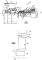
- FIG. 1 schematically illustrates a gas turbine engine 20.
- the gas turbine engine 20 is disclosed herein as a two-spool turbofan that generally incorporates a fan section 22, a compressor section 24, a combustor section 26 and a turbine section 28.
- the fan section 22 drives air along a bypass flow path B in a bypass duct defined within a housing 15 such as a fan case or nacelle, and also drives air along a core flow path C for compression and communication into the combustor section 26 then expansion through the turbine section 28.
- the exemplary engine 20 generally includes a low speed spool 30 and a high speed spool 32 mounted for rotation about an engine central longitudinal axis A relative to an engine static structure 36 via several bearing systems 38. It should be understood that various bearing systems 38 at various locations may alternatively or additionally be provided, and the location of bearing systems 38 may be varied as appropriate to the application.
- the low speed spool 30 generally includes an inner shaft 40 that interconnects, a first (or low) pressure compressor 44 and a first (or low) pressure turbine 46.
- the inner shaft 40 is connected to the fan 42 through a speed change mechanism, which in exemplary gas turbine engine 20 is illustrated as a geared architecture 48 to drive a fan 42 at a lower speed than the low speed spool 30.
- the high speed spool 32 includes an outer shaft 50 that interconnects a second (or high) pressure compressor 52 and a second (or high) pressure turbine 54.
- a combustor 56 is arranged in exemplary gas turbine 20 between the high pressure compressor 52 and the high pressure turbine 54.
- a mid-turbine frame 57 of the engine static structure 36 may be arranged generally between the high pressure turbine 54 and the low pressure turbine 46.
- the mid-turbine frame 57 further supports bearing systems 38 in the turbine section 28.
- the inner shaft 40 and the outer shaft 50 are concentric and rotate via bearing systems 38 about the engine central longitudinal axis A which is colline
- the core airflow is compressed by the low pressure compressor 44 then the high pressure compressor 52, mixed and burned with fuel in the combustor 56, then expanded through the high pressure turbine 54 and low pressure turbine 46.
- the mid-turbine frame 57 includes airfoils 59 which are in the core airflow path C.
- the turbines 46, 54 rotationally drive the respective low speed spool 30 and high speed spool 32 in response to the expansion.
- gear system 48 may be located aft of the low pressure compressor, or aft of the combustor section 26 or even aft of turbine section 28, and fan 42 may be positioned forward or aft of the location of gear system 48.
- the engine 20 in one example is a high-bypass geared aircraft engine.
- the engine 20 bypass ratio is greater than about six, with an example embodiment being greater than about ten
- the geared architecture 48 is an epicyclic gear train, such as a planetary gear system or other gear system, with a gear reduction ratio of greater than about 2.3 and the low pressure turbine 46 has a pressure ratio that is greater than about five.
- the engine 20 bypass ratio is greater than about ten
- the fan diameter is significantly larger than that of the low pressure compressor 44
- the low pressure turbine 46 has a pressure ratio that is greater than about five.
- Low pressure turbine 46 pressure ratio is pressure measured prior to inlet of low pressure turbine 46 as related to the pressure at the outlet of the low pressure turbine 46 prior to an exhaust nozzle.
- the geared architecture 48 may be an epicycle gear train, such as a planetary gear system or other gear system, with a gear reduction ratio of greater than about 2.3:1 and less than about 5:1. It should be understood, however, that the above parameters are only exemplary of one embodiment of a geared architecture engine and that the present invention is applicable to other gas turbine engines including direct drive turbofans.
- the fan section 22 of the engine 20 is designed for a particular flight condition -- typically cruise at about 0.8 Mach and about 35,000 feet (10,668 meters).
- the flight condition of 0.8 Mach and 35,000 ft (10,668 meters), with the engine at its best fuel consumption - also known as "bucket cruise Thrust Specific Fuel Consumption ('TSFC')" - is the industry standard parameter of lbm of fuel being burned divided by lbf of thrust the engine produces at that minimum point.
- "Low fan pressure ratio” is the pressure ratio across the fan blade alone, without a Fan Exit Guide Vane (“FEGV”) system.
- the low fan pressure ratio as disclosed herein according to one non-limiting embodiment is less than about 1.45.
- the "Low corrected fan tip speed” as disclosed herein according to one non-limiting embodiment is less than about 1150 ft / second (350.5 meters/second).
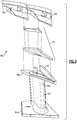
- Figures 2 illustrates a circumferential, wireframe view of a support system 60 from the turbine section 28 of the engine 20, including a vane support arc segment piece 62, a vane arc segment 64, an outer support structure 66, and an inner support structure 68.
- the support system 60 has a ring-strut-ring configuration in which the inner and outer support structures 66/68 serve as support rings and the vane arc segment 64 serves as a strut.
- the vane support arc segment pieces 62 are situated in a circumferential arrangement in the gas turbine engine 20, between a mating vane arc segment 64 in the core gas path and the adjacent outer support structure 66, such as a case.
- the vane support arc segment pieces 62 serve to transmit loads from the mating vane arc segment 64 to the outer support structure 66.
- the vane support arc segment pieces 62 may also serve as a thermal buffer between the vane arc segment 64 and a less thermally tolerant support structure 66. It is also to be appreciated that, although the vane support arc segment pieces 62 in the illustrated example are situated at the radially outer ends of the vane arc segments 64, in alternate embodiments the vane support arc segment pieces 62 may be at the radially inner ends of vane arc segments 64.
- FIG. 3 illustrates an expanded view of a portion of the support system 60
- Figure 4 illustrates an assembled view.
- the vane arc segment 64 includes first and second platforms 64a/64b and an airfoil section 64c that extends between the first and second platforms 64a/64b.
- the airfoil section 64c has a hollow interior 65 and defines a leading end, a trailing end, and pressure and suction sides.
- the first platform 64a is a radially outer platform and the second platform 64b is a radially inner platform.
- the first platform 64a includes a radial flange 70 that projects (radially) from the non-gaspath side thereof.
- the radial flange 70 is generally elongated in the axial direction.
- the vane arc segment 64 is formed of a ceramic material, such as a ceramic matrix composite that has ceramic fibers disposed in a ceramic matrix.
- the ceramic matrix composite may be, but is not limited to, a SiC/SiC ceramic matrix composite in which SiC fibers are disposed within a SiC matrix.
- each vane support arc segment piece 62 defines first and second radial sides 62a/62b, axially forward and aft sides 62c/62d, and first and second circumferential mate face sides 62e/62f.
- first radial side 62a is an inner radial side
- second radial side 62b is a radially outer side.
- the first radial side 62a would be an outer radial side and the second radial side 62b would be a radially inner side.
- the first radial side 62a has a radially open socket 67 that is generally elongated in an axial direction (relative to engine axis A).
- the radially open socket 67 extends from the axially forward side 62c to the axially aft side 62d and is curved along its length. It is also contemplated that the radially open socket 67 could extend only a partial length of the full distance between the sides 62c/62d, such as greater than at least 50% of the length.
- the socket 67 is differently curved, straight, faceted, or combinations thereof such that the socket 67 is complementary in geometry to that of a radial flange 70.
- the radially open socket 67 is configured by its shape to engage with the radial flange 70 of the vane arc segment 64.
- the radially open socket 67 is a slot that has a shape that is defined by opposed circumferential side walls 67a/67b, a floor wall 67c, and an axial wall 67d. As shown, the slot is three-sided, although in alternative examples the socket 67 may exclude one of the side walls 67a/67b depending on load transmission through the radial flange 70.
- the radial flange 70 is complementary in geometry to that of the radially open socket 67 such that the sides and top of the radial flange portion either contact or closely fit the side walls 67a/67b, floor wall 67c, and the axial wall 67d. Such contact or close fit enables loads to be transmitted from the vane arc segment 64 through the vane support arc segment piece 62 to the support structure 66.
- the vane support arc segment piece 62 also has radial and axial reaction surfaces 72a/72b.
- the radial reaction surface 72a is on the second radial side 62b, and the axial reaction surface 72b is on the axially aft side 62d.
- the radial and axial reaction surfaces 72a/72b are configured, respectively, to transmit radial and axial components of the loads to the support structure 66.
- the reaction surfaces 72a/72b are relatively large in order to distribute reaction loads, are complimentary in shape with mating surfaces on the support structure 66, and extend from the first circumferential mate face side 62e to the second circumferential mate face side 62f. If further load distribution is required, additional portions of the second radial side 62b may also serve as reaction surfaces.
- the vane support arc segment 62 also includes a seal slot 75.
- the seal slot 75 includes a circumferential leg 75a and axial legs 75b.
- one of the axial legs 75b is between the radially open socket 67 and the circumferential mate face side 62e, and the other axial leg 75b is between the radially open socket 67 and the circumferential mate face side 62f.
- the vane support arc segment piece 62 further defines a manifold region 82.
- the manifold region 82 is delimited by the axial wall 67d, the side wall 67a, and radial wall 84 (which also forms the floor wall 67c).
- the perimeter of the opening 86 is defined, in part, by the radial wall 86, and the remaining perimeter of the opening 86 is defined by the circumferential mate face side 62f of the neighboring vane support arc segment piece 62.
- cooling air such as bleed air from the compressor section 24
- the airfoil section 64c may use the cooling air for cooling and/or guide the cooling air on to a downstream passage to another component for cooling.
- the second radial side 62b has an anti-rotation lock 90.
- the lock 90 is a protrusion that is substantially rectangular in cross-section in order to distribute loads.
- the lock 90 engages with the outer support structure 66 to limit rotational (circumferential) movement of the vane support arc segment piece 62.
- loads on the vane arc segments 64 are transmitted from the radial flange 70 to the vane support arc segment pieces 62 via the radially open sockets 67.
- loads on the vane arc segments 64 are transmitted from the radial flange 70 to the vane support arc segment pieces 62 via the radially open sockets 67.
- the radial component of the loads are received into the vane support arc segment piece 62 through the floor wall 67c of the socket 67
- the axial component of the loads are received into the vane support arc segment piece 62 via through the axial wall 67d of the socket 67.
- the support arc segment piece 62 then transmits the radial loads through the radial reaction surface 72a to the support structure 66 and transmits the axial loads through the axial reaction surface 72b to the support structure 66.
- the side walls 67a/67b facilitate constraining the radial flange 70, such as constraining circumferential movement.
- the side wall 74a may be excluded or, of the load direction is reverse, the side wall 67b may be excluded.
- the vane support arc segment piece 62 may also serve as a thermal buffer.
- ceramic vane arc segments 64 may operate at very high temperatures.
- the vane support arc segment piece 62 may be formed of a single crystal alloy, which enables the vane support arc segment piece 62 to maintain high strength at high exposure temperatures while also shielding the support structure 66 from the high temperatures.
- the vane support arc segment piece 62 may be formed of a ceramic material, such as a ceramic matrix composite.
- the vane support arc segment piece 62 is in essence sandwiched between the vane arc segment 64 and the support structure 66 rather than being rigidly affixed, the vane support arc segment piece 62 facilitates reducing thermal constraints that may otherwise induce higher stresses.
- FIG. 6 shows an isolated view of the seal 74.
- the seal 74 includes a first seal section 76 and a second seal section 78 that nests with the first seal section 76.
- the term "nests" refers to the second seal section 78 fitting closely in the first seal section 76, for example by conformance of the geometries of the first and second seal sections 76/78.
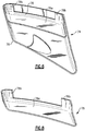
- Figures 7A, 7B, and 7C illustrate isolated views of the first seal section 76.
- the first seal section 76 has a floor wall 76a and side walls 76b that project from the floor wall 76a, away from the vane arc segment 64.
- the floor wall 76a includes a through-hole 77. In the installed position the through-hole 77 sits adjacent the hollow interior 65 of the airfoil section 64c. In this example, the through-hole 77 has an airfoil shape that corresponds to the airfoil shape of the airfoil section 64c.
- Adjacent ones of the side walls 76b may be considered to be first and second side walls 76b.
- the first seal section 76 has three side walls 76b but may alternatively have fewer or additional side walls 76b.
- the side walls 76b converge to define one or more disjointed corners 80 (two in this example).
- the side walls 76b extend into the seal slot 75 in the vane support arc segment piece 62.
- the seal 74 spans between two adjacent vane support arc segment pieces 62 such that a portion of the side walls 76b are disposed in the portion of the seal slot 75 to one side of the radially open socket 67 and another portion of the side walls 76b are disposed in the portion of the seal slot 75 to the other side of the radially open socket 67 in the next adjacent vane support arc segment piece 62.
- each seal 74 spans two vane support arc segment pieces 62.
- the cooling air is fed into the hollow interior 65 of the airfoil section 64c.
- the first seal section 76 facilitates preventing the cooling air from leaking and escaping.
- the floor wall 76a conforms to the radially outer side of the platform 64a (as indicated at Z in Figure 4 ), and the side walls 76b conform against the sides of the seal slot 75.
- the pressure of the cooling air facilitates pushing the floor wall 76a against the radially outer side of the platform 64a and the side walls 76b against the sides of the seal slot 75.
- the disjointed corners 80 in the first seal section 76 are the regions at which the side walls 76b would meet but for gaps 80a between opposed edges 80b of the side walls 76b ( Figure 7C ).
- the side walls 76b are, therefore, not directly connected to each other.
- Each gap 80a defines a width (w) between the opposed edges 80b and a height (h) from the bottom to the top of the gap 80a.
- the size of the gap 80a in terms of the width (w) is greater than the wall thickness (t) of the side walls 76b.
- the disjointed corners 80 facilitate enhancing the compliance of each side wall 76b, since each side wall 76b is able to flex without constraint from the adjacent side wall 76b.
- the enhanced compliance facilitates conformance of the side walls 76b against the sides of the seal slot 75 to provide good sealing.
- the gap 80a ends at the floor wall 76a.
- the gap 80a can be extended into the floor wall 76a to facilitate additional compliance.
- the gaps 80a may provide a leak path.
- the second seal section 78 nests with the first seal section 76 and seals the disjointed corners 80.
- Figure 8 illustrates an isolated view of the second seal section 78.
- the second seal section 78 includes a base wall 78a and one or more corner sections 78b (two in this example) that project from the base wall 78a.
- the base wall 78a conforms or substantially conforms to the floor wall 76a of the first seal section 76
- the corner sections 78b conform or substantially conform to the disjointed corners 80.
- the corner sections 78b cover the gaps 80a to close off the gaps 80a as leak paths.
- each corner section 78b spans entirely across the width (w) and height (h) of the gap 80a.
- the pressure of the cooling air biases the second seal section 78 against the first seal section 76, to maintain the nested position.
- the seal 74 may have a single group with one corner 80 and one corner section 78 or more than two groups of disjointed corners 80 and corner sections 78, such as three or four groups.
Landscapes
- Engineering & Computer Science (AREA)
- General Engineering & Computer Science (AREA)
- Mechanical Engineering (AREA)
- Physics & Mathematics (AREA)
- Fluid Mechanics (AREA)
- Turbine Rotor Nozzle Sealing (AREA)
Abstract
Description
- A gas turbine engine typically includes a fan section, a compressor section, a combustor section and a turbine section. Air entering the compressor section is compressed and delivered into the combustion section where it is mixed with fuel and ignited to generate a high-speed exhaust gas flow. The high-speed exhaust gas flow expands through the turbine section to drive the compressor and the fan section. The compressor section typically includes low and high pressure compressors, and the turbine section includes low and high pressure turbines.
- Airfoils in the turbine section are typically formed of a superalloy and may include thermal barrier coatings to extend temperature resistance. Ceramics, such as ceramic matrix composite ("CMC") materials, are also being considered for airfoils. CMCs have high temperature resistance. Despite this attribute, there are unique challenges to implementing CMCs in airfoils.
- A gas turbine engine support system according to an example of the present disclosure includes a vane arc segment, a vane support arc segment piece configured to engage the vane arc segment, and a seal disposed radially between the vane arc segment and the vane support arc segment piece. The seal includes a first seal section that has a floor wall and first and second side walls that project from the floor wall. The first and second side walls converge to define a disjointed corner, and a second seal section nests with the first seal section and seals the disjointed corner.
- In a further embodiment of any of the foregoing embodiments, the second seal section includes a base wall and a corner section projecting from the base wall. The corner section conforms to the disjointed corner.
- In a further embodiment of any of the foregoing embodiments, the base wall conforms to the floor wall of the first seal section.
- In a further embodiment of any of the foregoing embodiments, the disjointed corner includes a gap, and the second seal section fully covers the gap.
- In a further embodiment of any of the foregoing embodiments, the vane arc segment includes an airfoil section having a hollow interior, and the floor wall includes a through-hole that opens to the hollow interior.
- In a further embodiment of any of the foregoing embodiments, the through-hole is airfoil-shaped.
- In a further embodiment of any of the foregoing embodiments, the side walls project away from the vane arc segment.
- In a further embodiment of any of the foregoing embodiments, the vane support arc segment includes a seal slot and at least one of the first and second side walls extends into the seal slot.
- In a further embodiment of any of the foregoing embodiments, the vane arc segment includes a platform, and the floor wall conforms to the platform.
- In a further embodiment of any of the foregoing embodiments, the first and second side walls have a wall thickness. The disjointed corner includes a gap between edges of the side walls that define a gap size, and the gap size is greater than the wall thickness.
- A seal for a gas turbine engine support system according to an example of the present disclosure includes a first seal section that has a floor wall and first and second side walls that project from the floor wall. The first and second side walls converge to define a disjointed corner, and a second seal section nests with the first seal section and seals the disjointed corner.
- In a further embodiment of any of the foregoing embodiments, the second seal section includes a base wall and a corner section projecting from the base wall. The corner section conforms to the disjointed corner.
- In a further embodiment of any of the foregoing embodiments, the base wall conforms to the floor wall of the first seal section.
- In a further embodiment of any of the foregoing embodiments, the disjointed corner includes a gap, and the second seal section fully covers the gap.
- In a further embodiment of any of the foregoing embodiments, the floor wall includes a through-hole.
- In a further embodiment of any of the foregoing embodiments, the through-hole is airfoil-shaped.
- A gas turbine engine support system according to an example of the present disclosure includes an outer case and vane support arc segment pieces that interface with the outer case. Each said vane support arc segment piece defines a radially open socket. Each vane arc segment defines a platform and an airfoil section that extends from the platform. The platform defines a radial flange of complementary geometry to the radially open sockets of the vane support arc segment pieces. The radial flange projects into a corresponding one of the radially open sockets. There are seals disposed radially between the vane arc segments and the vane support arc segment pieces. Each seal includes a first seal section that has a floor wall and side walls that project from the floor wall. The side walls converge to define first and second disjointed corners, and a second seal section nests with the first seal section and seals the first and second disjointed corners.
- In a further embodiment of any of the foregoing embodiments, the seal spans first and second adjacent ones of the vane support arc segments.
- In a further embodiment of any of the foregoing embodiments, the first disjointed corner is in the first vane support arc segment, and the second disjointed corner is in the second vane support arc segment.
- In a further embodiment of any of the foregoing embodiments, each said radially open socket is circumferentially between two of the seals.
- The various features and advantages of the present disclosure will become apparent to those skilled in the art from the following detailed description. The drawings that accompany the detailed description can be briefly described as follows.
-
Figure 1 illustrates a gas turbine engine. -
Figure 2 illustrates a wireframe view of a vane support system. -
Figure 3 illustrates an expanded view of portions of a vane support system. -
Figure 4 illustrates an assembled view of a vane support system. -
Figure 5A illustrates a vane support arc segment. -
Figure 5B illustrates another view of the vane support arc segment. -
Figure 6 illustrates a seal. -
Figure 7A illustrates an isolated view of a first seal section of the seal. -
Figure 7B illustrates another view of the first seal section. -
Figure 7C illustrates another view of the first seal section. -
Figure 8 illustrates an isolated view of a second seal section of the seal. -
Figure 1 schematically illustrates agas turbine engine 20. Thegas turbine engine 20 is disclosed herein as a two-spool turbofan that generally incorporates afan section 22, acompressor section 24, acombustor section 26 and aturbine section 28. Thefan section 22 drives air along a bypass flow path B in a bypass duct defined within ahousing 15 such as a fan case or nacelle, and also drives air along a core flow path C for compression and communication into thecombustor section 26 then expansion through theturbine section 28. Although depicted as a two-spool turbofan gas turbine engine in the disclosed non-limiting embodiment, it should be understood that the concepts described herein are not limited to use with two-spool turbofans as the teachings may be applied to other types of turbine engines including three-spool architectures. - The
exemplary engine 20 generally includes alow speed spool 30 and ahigh speed spool 32 mounted for rotation about an engine central longitudinal axis A relative to an enginestatic structure 36 viaseveral bearing systems 38. It should be understood thatvarious bearing systems 38 at various locations may alternatively or additionally be provided, and the location ofbearing systems 38 may be varied as appropriate to the application. - The
low speed spool 30 generally includes aninner shaft 40 that interconnects, a first (or low)pressure compressor 44 and a first (or low) pressure turbine 46. Theinner shaft 40 is connected to thefan 42 through a speed change mechanism, which in exemplarygas turbine engine 20 is illustrated as a gearedarchitecture 48 to drive afan 42 at a lower speed than thelow speed spool 30. Thehigh speed spool 32 includes anouter shaft 50 that interconnects a second (or high) pressure compressor 52 and a second (or high) pressure turbine 54. Acombustor 56 is arranged inexemplary gas turbine 20 between the high pressure compressor 52 and the high pressure turbine 54. Amid-turbine frame 57 of the enginestatic structure 36 may be arranged generally between the high pressure turbine 54 and the low pressure turbine 46. Themid-turbine frame 57 furthersupports bearing systems 38 in theturbine section 28. Theinner shaft 40 and theouter shaft 50 are concentric and rotate via bearingsystems 38 about the engine central longitudinal axis A which is collinear with their longitudinal axes. - The core airflow is compressed by the
low pressure compressor 44 then the high pressure compressor 52, mixed and burned with fuel in thecombustor 56, then expanded through the high pressure turbine 54 and low pressure turbine 46. Themid-turbine frame 57 includesairfoils 59 which are in the core airflow path C. The turbines 46, 54 rotationally drive the respectivelow speed spool 30 andhigh speed spool 32 in response to the expansion. It will be appreciated that each of the positions of thefan section 22,compressor section 24,combustor section 26,turbine section 28, and fandrive gear system 48 may be varied. For example,gear system 48 may be located aft of the low pressure compressor, or aft of thecombustor section 26 or even aft ofturbine section 28, andfan 42 may be positioned forward or aft of the location ofgear system 48. - The
engine 20 in one example is a high-bypass geared aircraft engine. In a further example, theengine 20 bypass ratio is greater than about six, with an example embodiment being greater than about ten, the gearedarchitecture 48 is an epicyclic gear train, such as a planetary gear system or other gear system, with a gear reduction ratio of greater than about 2.3 and the low pressure turbine 46 has a pressure ratio that is greater than about five. In one disclosed embodiment, theengine 20 bypass ratio is greater than about ten, the fan diameter is significantly larger than that of thelow pressure compressor 44, and the low pressure turbine 46 has a pressure ratio that is greater than about five. Low pressure turbine 46 pressure ratio is pressure measured prior to inlet of low pressure turbine 46 as related to the pressure at the outlet of the low pressure turbine 46 prior to an exhaust nozzle. The gearedarchitecture 48 may be an epicycle gear train, such as a planetary gear system or other gear system, with a gear reduction ratio of greater than about 2.3:1 and less than about 5:1. It should be understood, however, that the above parameters are only exemplary of one embodiment of a geared architecture engine and that the present invention is applicable to other gas turbine engines including direct drive turbofans. - A significant amount of thrust is provided by the bypass flow B due to the high bypass ratio. The
fan section 22 of theengine 20 is designed for a particular flight condition -- typically cruise at about 0.8 Mach and about 35,000 feet (10,668 meters). The flight condition of 0.8 Mach and 35,000 ft (10,668 meters), with the engine at its best fuel consumption - also known as "bucket cruise Thrust Specific Fuel Consumption ('TSFC')" - is the industry standard parameter of lbm of fuel being burned divided by lbf of thrust the engine produces at that minimum point. "Low fan pressure ratio" is the pressure ratio across the fan blade alone, without a Fan Exit Guide Vane ("FEGV") system. The low fan pressure ratio as disclosed herein according to one non-limiting embodiment is less than about 1.45. "Low corrected fan tip speed" is the actual fan tip speed in ft/sec divided by an industry standard temperature correction of [(Tram °R) / (518.7 °R)]0.5 (where °R = K x 9/5). The "Low corrected fan tip speed" as disclosed herein according to one non-limiting embodiment is less than about 1150 ft / second (350.5 meters/second). -
Figures 2 illustrates a circumferential, wireframe view of asupport system 60 from theturbine section 28 of theengine 20, including a vane supportarc segment piece 62, avane arc segment 64, anouter support structure 66, and aninner support structure 68. Generally, thesupport system 60 has a ring-strut-ring configuration in which the inner andouter support structures 66/68 serve as support rings and thevane arc segment 64 serves as a strut. The vane supportarc segment pieces 62 are situated in a circumferential arrangement in thegas turbine engine 20, between a matingvane arc segment 64 in the core gas path and the adjacentouter support structure 66, such as a case. The vane supportarc segment pieces 62 serve to transmit loads from the matingvane arc segment 64 to theouter support structure 66. The vane supportarc segment pieces 62 may also serve as a thermal buffer between thevane arc segment 64 and a less thermallytolerant support structure 66. It is also to be appreciated that, although the vane supportarc segment pieces 62 in the illustrated example are situated at the radially outer ends of thevane arc segments 64, in alternate embodiments the vane supportarc segment pieces 62 may be at the radially inner ends ofvane arc segments 64. -
Figure 3 illustrates an expanded view of a portion of thesupport system 60, andFigure 4 illustrates an assembled view. Thevane arc segment 64 includes first andsecond platforms 64a/64b and anairfoil section 64c that extends between the first andsecond platforms 64a/64b. Theairfoil section 64c has ahollow interior 65 and defines a leading end, a trailing end, and pressure and suction sides. In this example, thefirst platform 64a is a radially outer platform and thesecond platform 64b is a radially inner platform. Thefirst platform 64a includes aradial flange 70 that projects (radially) from the non-gaspath side thereof. Theradial flange 70 is generally elongated in the axial direction. - The
vane arc segment 64 is formed of a ceramic material, such as a ceramic matrix composite that has ceramic fibers disposed in a ceramic matrix. The ceramic matrix composite may be, but is not limited to, a SiC/SiC ceramic matrix composite in which SiC fibers are disposed within a SiC matrix. - Referring also to isolated views of the vane support
arc segment piece 62 inFigures 5A and 5B , each vane supportarc segment piece 62 defines first and secondradial sides 62a/62b, axially forward andaft sides 62c/62d, and first and second circumferentialmate face sides 62e/62f. In the illustrated example, the firstradial side 62a is an inner radial side and the secondradial side 62b is a radially outer side. Alternatively, if the vane supportarc segment piece 62 were located at the radially inner end of thevane arc segment 64, the firstradial side 62a would be an outer radial side and the secondradial side 62b would be a radially inner side. - The first
radial side 62a has a radiallyopen socket 67 that is generally elongated in an axial direction (relative to engine axis A). In the illustrated example, the radiallyopen socket 67 extends from the axiallyforward side 62c to the axially aftside 62d and is curved along its length. It is also contemplated that the radiallyopen socket 67 could extend only a partial length of the full distance between thesides 62c/62d, such as greater than at least 50% of the length. In further examples, thesocket 67 is differently curved, straight, faceted, or combinations thereof such that thesocket 67 is complementary in geometry to that of aradial flange 70. - The radially
open socket 67 is configured by its shape to engage with theradial flange 70 of thevane arc segment 64. In this example, the radiallyopen socket 67 is a slot that has a shape that is defined by opposedcircumferential side walls 67a/67b, a floor wall 67c, and anaxial wall 67d. As shown, the slot is three-sided, although in alternative examples thesocket 67 may exclude one of theside walls 67a/67b depending on load transmission through theradial flange 70. Theradial flange 70 is complementary in geometry to that of the radiallyopen socket 67 such that the sides and top of the radial flange portion either contact or closely fit theside walls 67a/67b, floor wall 67c, and theaxial wall 67d. Such contact or close fit enables loads to be transmitted from thevane arc segment 64 through the vane supportarc segment piece 62 to thesupport structure 66. In that regard, the vane supportarc segment piece 62 also has radial and axial reaction surfaces 72a/72b. - The
radial reaction surface 72a is on the secondradial side 62b, and theaxial reaction surface 72b is on the axially aftside 62d. The radial and axial reaction surfaces 72a/72b are configured, respectively, to transmit radial and axial components of the loads to thesupport structure 66. For example, the reaction surfaces 72a/72b are relatively large in order to distribute reaction loads, are complimentary in shape with mating surfaces on thesupport structure 66, and extend from the first circumferentialmate face side 62e to the second circumferentialmate face side 62f. If further load distribution is required, additional portions of the secondradial side 62b may also serve as reaction surfaces. - The vane
support arc segment 62 also includes aseal slot 75. Theseal slot 75 includes acircumferential leg 75a andaxial legs 75b. In this example, one of theaxial legs 75b is between the radiallyopen socket 67 and the circumferentialmate face side 62e, and the otheraxial leg 75b is between the radiallyopen socket 67 and the circumferentialmate face side 62f. - The vane support
arc segment piece 62 further defines amanifold region 82. Themanifold region 82 is delimited by theaxial wall 67d, theside wall 67a, and radial wall 84 (which also forms the floor wall 67c). There is at least oneopening 86 that connects the firstradial side 62b with themanifold region 82. The perimeter of theopening 86 is defined, in part, by theradial wall 86, and the remaining perimeter of theopening 86 is defined by the circumferentialmate face side 62f of the neighboring vane supportarc segment piece 62. In this regard, cooling air, such as bleed air from thecompressor section 24, can be provided to the firstradial side 62b, flow through theopening 86 into themanifold region 82, and flow from themanifold region 82 into thehollow interior 65 of theairfoil section 64c. Theairfoil section 64c may use the cooling air for cooling and/or guide the cooling air on to a downstream passage to another component for cooling. - Optionally, the second
radial side 62b has ananti-rotation lock 90. In this example, thelock 90 is a protrusion that is substantially rectangular in cross-section in order to distribute loads. Thelock 90 engages with theouter support structure 66 to limit rotational (circumferential) movement of the vane supportarc segment piece 62. - During operation of the
engine 20, loads on thevane arc segments 64, such as aerodynamic loads, are transmitted from theradial flange 70 to the vane supportarc segment pieces 62 via the radiallyopen sockets 67. For example, the radial component of the loads are received into the vane supportarc segment piece 62 through the floor wall 67c of thesocket 67, and the axial component of the loads are received into the vane supportarc segment piece 62 via through theaxial wall 67d of thesocket 67. The supportarc segment piece 62 then transmits the radial loads through theradial reaction surface 72a to thesupport structure 66 and transmits the axial loads through theaxial reaction surface 72b to thesupport structure 66. Theside walls 67a/67b facilitate constraining theradial flange 70, such as constraining circumferential movement. In that regard, in modified examples the side wall 74a may be excluded or, of the load direction is reverse, theside wall 67b may be excluded. - The vane support
arc segment piece 62 may also serve as a thermal buffer. For example, ceramicvane arc segments 64 may operate at very high temperatures. The vane supportarc segment piece 62 may be formed of a single crystal alloy, which enables the vane supportarc segment piece 62 to maintain high strength at high exposure temperatures while also shielding thesupport structure 66 from the high temperatures. Alternatively, if stresses are relatively low, the vane supportarc segment piece 62 may be formed of a ceramic material, such as a ceramic matrix composite. Moreover, since the vane supportarc segment piece 62 is in essence sandwiched between thevane arc segment 64 and thesupport structure 66 rather than being rigidly affixed, the vane supportarc segment piece 62 facilitates reducing thermal constraints that may otherwise induce higher stresses. - Referring again to
Figures 3 and4 , there is also aseal 74 disposed radially between thevane arc segment 64 and the vane supportarc segment piece 62.Figure 6 shows an isolated view of theseal 74. Theseal 74 includes afirst seal section 76 and asecond seal section 78 that nests with thefirst seal section 76. The term "nests" refers to thesecond seal section 78 fitting closely in thefirst seal section 76, for example by conformance of the geometries of the first andsecond seal sections 76/78. -
Figures 7A, 7B, and 7C illustrate isolated views of thefirst seal section 76. Thefirst seal section 76 has afloor wall 76a andside walls 76b that project from thefloor wall 76a, away from thevane arc segment 64. Thefloor wall 76a includes a through-hole 77. In the installed position the through-hole 77 sits adjacent thehollow interior 65 of theairfoil section 64c. In this example, the through-hole 77 has an airfoil shape that corresponds to the airfoil shape of theairfoil section 64c. - Adjacent ones of the
side walls 76b may be considered to be first andsecond side walls 76b. In the illustrated example, thefirst seal section 76 has threeside walls 76b but may alternatively have fewer oradditional side walls 76b. Theside walls 76b converge to define one or more disjointed corners 80 (two in this example). Theside walls 76b extend into theseal slot 75 in the vane supportarc segment piece 62. As shown inFigures 3 and4 , theseal 74 spans between two adjacent vane supportarc segment pieces 62 such that a portion of theside walls 76b are disposed in the portion of theseal slot 75 to one side of the radiallyopen socket 67 and another portion of theside walls 76b are disposed in the portion of theseal slot 75 to the other side of the radiallyopen socket 67 in the next adjacent vane supportarc segment piece 62. Thus, eachseal 74 spans two vane supportarc segment pieces 62. - The cooling air is fed into the
hollow interior 65 of theairfoil section 64c. Thefirst seal section 76 facilitates preventing the cooling air from leaking and escaping. For instance, thefloor wall 76a conforms to the radially outer side of theplatform 64a (as indicated at Z inFigure 4 ), and theside walls 76b conform against the sides of theseal slot 75. The pressure of the cooling air facilitates pushing thefloor wall 76a against the radially outer side of theplatform 64a and theside walls 76b against the sides of theseal slot 75. - The
disjointed corners 80 in thefirst seal section 76 are the regions at which theside walls 76b would meet but forgaps 80a betweenopposed edges 80b of theside walls 76b (Figure 7C ). Theside walls 76b are, therefore, not directly connected to each other. Eachgap 80a defines a width (w) between theopposed edges 80b and a height (h) from the bottom to the top of thegap 80a. In general, the size of thegap 80a in terms of the width (w) is greater than the wall thickness (t) of theside walls 76b. - The
disjointed corners 80 facilitate enhancing the compliance of eachside wall 76b, since eachside wall 76b is able to flex without constraint from theadjacent side wall 76b. In turn, the enhanced compliance facilitates conformance of theside walls 76b against the sides of theseal slot 75 to provide good sealing. In the illustrated example, in the length direction (i.e., radial direction), thegap 80a ends at thefloor wall 76a. However, in modified examples, thegap 80a can be extended into thefloor wall 76a to facilitate additional compliance. - The
gaps 80a, however, may provide a leak path. In this regard, thesecond seal section 78 nests with thefirst seal section 76 and seals thedisjointed corners 80.Figure 8 illustrates an isolated view of thesecond seal section 78. Thesecond seal section 78 includes abase wall 78a and one ormore corner sections 78b (two in this example) that project from thebase wall 78a. In order to nest, thebase wall 78a conforms or substantially conforms to thefloor wall 76a of thefirst seal section 76, and thecorner sections 78b conform or substantially conform to thedisjointed corners 80. Thecorner sections 78b cover thegaps 80a to close off thegaps 80a as leak paths. For example, eachcorner section 78b spans entirely across the width (w) and height (h) of thegap 80a. The pressure of the cooling air biases thesecond seal section 78 against thefirst seal section 76, to maintain the nested position. It is to be appreciated that although theseal 74 has twodisjointed corners 80 and two corner sections 78 (i.e., two groups ofcorners 80 and corner section 78) that nest with and seal thedisjointed corners 80, that in alternate examples theseal 74 may have a single group with onecorner 80 and onecorner section 78 or more than two groups ofdisjointed corners 80 andcorner sections 78, such as three or four groups. - Although a combination of features is shown in the illustrated examples, not all of them need to be combined to realize the benefits of various embodiments of this disclosure. In other words, a system designed according to an embodiment of this disclosure will not necessarily include all of the features shown in any one of the Figures or all of the portions schematically shown in the Figures. Moreover, selected features of one example embodiment may be combined with selected features of other example embodiments.
- The preceding description is exemplary rather than limiting in nature. Variations and modifications to the disclosed examples may become apparent to those skilled in the art that do not necessarily depart from this disclosure. The scope of legal protection given to this disclosure can only be determined by studying the following claims.
Claims (15)
- A gas turbine engine support system (60) comprising:a vane arc segment (64);a vane support arc segment piece (62) configured to engage the vane arc segment (64); anda seal (74) disposed radially between the vane arc segment (64) and the vane support arc segment piece (62), the seal (74) includinga first seal section (76) having a floor wall (76a) and first and second side walls (76b) projecting from the floor wall (76a), the first and second side walls (76b) converging to define a disjointed corner (80), anda second seal section (78) nesting with the first seal section (76) and sealing the disjointed corner (80).
- The system (60) as recited in claim 1, wherein the second seal section (78) includes a base wall (78a) and a corner section (78b) projecting from the base wall (78a), the corner section (78b) conforming to the disjointed corner (80), optionally wherein the base wall (78a) conforms to the floor wall (76a) of the first seal section (76).
- The system (60) as recited in claim 1 or 2, wherein the disjointed corner (80) includes a gap (80a), and the second seal section (78) fully covers the gap (80a).
- The system (60) as recited in any preceding claim, wherein the vane arc segment (64) includes an airfoil section (64c) having a hollow interior (65), and the floor wall (76a) includes a through-hole (77) that opens to the hollow interior (65), optionally wherein the through-hole (77) is airfoil-shaped.
- The system (60) as recited in any preceding claim, wherein the side walls (76b) project away from the vane arc segment (64).
- The system (60) as recited in any preceding claim, wherein the vane support arc segment (62) includes a seal slot (75) and at least one of the first and second side walls (76b) extends into the seal slot (75).
- The system (60) as recited in any preceding claim, wherein the vane arc segment (64) includes a platform (64a), and the floor wall (76a) conforms to the platform (64a).
- The system as recited in any preceding claim, wherein the first and second side walls (76b) have a wall thickness (t), the disjointed corner (80) includes a gap (80a) between edges of the side walls (76b) that define a gap size, and the gap size is greater than the wall thickness (t).
- A seal (74) for a gas turbine engine support system (60), the seal (74) comprising:a first seal section (76) having a floor wall (76a) and first and second side walls (76b) projecting from the floor wall (76a), the first and second side walls (76b) converging to define a disjointed corner (80), anda second seal section (78) nesting with the first seal section (76) and sealing the disjointed corner (80).
- The seal (74) as recited in claim 9, wherein the second seal section (78) includes a base wall (78a) and a corner section (78b) projecting from the base wall (78a), the corner section (78b) conforming to the disjointed corner (80), optionally wherein the base wall (78a) conforms to the floor wall (76a) of the first seal section (76).
- The seal (74) as recited in claim 9 or 10, wherein the disjointed corner (80) includes a gap (80a), and the second seal section (78) fully covers the gap (80a).
- The seal (74) as recited in any of claims 9 to 11, wherein the floor wall (76a) includes a through-hole (77), optionally wherein the through-hole (77) is airfoil-shaped.
- A gas turbine engine support system (60) comprising:an outer case (66);vane support arc segment pieces (62) interfacing with the outer case (66), each said vane support arc segment piece (62) defining a radially open socket (67);vane arc segments (64), each said vane arc segment (64) defining a platform (64a) and an airfoil section (64c) extending from the platform (64a), the platform (64a) defining a radial flange (70) of complementary geometry to the radially open sockets (67) of the vane support arc segment pieces (62), the radial flange (70) projecting into a corresponding one of the radially open sockets (67); andseals (74) disposed radially between the vane arc segments (64) and the vane support arc segment pieces (62), each said seal (74) including a first seal section (76) having a floor wall (76a) and side walls (76b) projecting from the floor wall (76a), the side walls (76b) converging to define first and second disjointed corners (80), and a second seal section (78) nesting with the first seal section (76) and sealing the first and second disjointed corners (80).
- The system (60) as recited in claim 13, wherein the seal (74) spans first and second adjacent ones of the vane support arc segments (64), optionally wherein the first disjointed corner (80) is in the first vane support arc segment (64), and the second disjointed corner (80) is in the second vane support arc segment (64).
- The system (60) as recited in claim 13 or 14, wherein each said radially open socket (67) is circumferentially between two of the seals (74).
Applications Claiming Priority (1)
| Application Number | Priority Date | Filing Date | Title |
|---|---|---|---|
| US16/844,625 US11365642B2 (en) | 2020-04-09 | 2020-04-09 | Vane support system with seal |
Publications (2)
| Publication Number | Publication Date |
|---|---|
| EP3892823A1 true EP3892823A1 (en) | 2021-10-13 |
| EP3892823B1 EP3892823B1 (en) | 2024-05-29 |
Family
ID=75441815
Family Applications (1)
| Application Number | Title | Priority Date | Filing Date |
|---|---|---|---|
| EP21167668.9A Active EP3892823B1 (en) | 2020-04-09 | 2021-04-09 | Seal for a support system for a vane arc segment |
Country Status (2)
| Country | Link |
|---|---|
| US (1) | US11365642B2 (en) |
| EP (1) | EP3892823B1 (en) |
Cited By (2)
| Publication number | Priority date | Publication date | Assignee | Title |
|---|---|---|---|---|
| EP4086434A3 (en) * | 2021-05-04 | 2023-01-25 | Raytheon Technologies Corporation | Cmc vane with platform cover |
| EP4276279A1 (en) * | 2022-05-13 | 2023-11-15 | RTX Corporation | Ceramic vane ring-strut-ring attachment configuration |
Citations (6)
| Publication number | Priority date | Publication date | Assignee | Title |
|---|---|---|---|---|
| EP1164252A2 (en) * | 2000-06-13 | 2001-12-19 | General Electric Company | Support pedestals for a wall cover in a gas turbine nozzle segment |
| EP1548234A2 (en) * | 2003-12-26 | 2005-06-29 | General Electric Company | Impingement baffle with embedded deflector |
| DE102005024696A1 (en) * | 2004-06-15 | 2006-01-05 | Alstom Technology Ltd | Component part of especially turbo-engine has protective shroud installed around sleeve element to protect section of sleeve element protruding from cooling passage against effects of surrounding flow |
| EP2366873A2 (en) * | 2010-03-17 | 2011-09-21 | United Technologies Corporation | Cover plate for turbine vane assembly |
| WO2013162928A1 (en) * | 2012-04-27 | 2013-10-31 | General Electric Company | Turbine nozzle outer band and airfoil cooling apparatus |
| WO2014186166A1 (en) * | 2013-05-16 | 2014-11-20 | Siemens Energy, Inc. | Cooling arrangement having a snap-in impingement plate |
Family Cites Families (12)
| Publication number | Priority date | Publication date | Assignee | Title |
|---|---|---|---|---|
| GB0124914D0 (en) * | 2001-10-17 | 2001-12-05 | Symonds Downhole Tooling Ltd | Downhole tool |
| FR2840352B1 (en) * | 2002-05-30 | 2005-12-16 | Snecma Moteurs | MASTING THE LEAK AREA UNDER A DAWN PLATFORM |
| US8096758B2 (en) * | 2008-09-03 | 2012-01-17 | Siemens Energy, Inc. | Circumferential shroud inserts for a gas turbine vane platform |
| US9546557B2 (en) | 2012-06-29 | 2017-01-17 | General Electric Company | Nozzle, a nozzle hanger, and a ceramic to metal attachment system |
| US10655482B2 (en) | 2015-02-05 | 2020-05-19 | Rolls-Royce Corporation | Vane assemblies for gas turbine engines |
| US10208614B2 (en) * | 2016-02-26 | 2019-02-19 | General Electric Company | Apparatus, turbine nozzle and turbine shroud |
| US10514005B2 (en) * | 2017-02-24 | 2019-12-24 | Unison Industries, Llc | Turbine engine thermal seal |
| US10774665B2 (en) * | 2018-07-31 | 2020-09-15 | General Electric Company | Vertically oriented seal system for gas turbine vanes |
| US10927689B2 (en) | 2018-08-31 | 2021-02-23 | Rolls-Royce Corporation | Turbine vane assembly with ceramic matrix composite components mounted to case |
| US11162368B2 (en) * | 2019-06-13 | 2021-11-02 | Raytheon Technologies Corporation | Airfoil assembly with ceramic airfoil pieces and seal |
| US11187096B2 (en) * | 2019-11-07 | 2021-11-30 | Raytheon Technologies Corporation | Platform seal |
| US11346234B2 (en) * | 2020-01-02 | 2022-05-31 | Rolls-Royce Plc | Turbine vane assembly incorporating ceramic matrix composite materials |
-
2020
- 2020-04-09 US US16/844,625 patent/US11365642B2/en active Active
-
2021
- 2021-04-09 EP EP21167668.9A patent/EP3892823B1/en active Active
Patent Citations (6)
| Publication number | Priority date | Publication date | Assignee | Title |
|---|---|---|---|---|
| EP1164252A2 (en) * | 2000-06-13 | 2001-12-19 | General Electric Company | Support pedestals for a wall cover in a gas turbine nozzle segment |
| EP1548234A2 (en) * | 2003-12-26 | 2005-06-29 | General Electric Company | Impingement baffle with embedded deflector |
| DE102005024696A1 (en) * | 2004-06-15 | 2006-01-05 | Alstom Technology Ltd | Component part of especially turbo-engine has protective shroud installed around sleeve element to protect section of sleeve element protruding from cooling passage against effects of surrounding flow |
| EP2366873A2 (en) * | 2010-03-17 | 2011-09-21 | United Technologies Corporation | Cover plate for turbine vane assembly |
| WO2013162928A1 (en) * | 2012-04-27 | 2013-10-31 | General Electric Company | Turbine nozzle outer band and airfoil cooling apparatus |
| WO2014186166A1 (en) * | 2013-05-16 | 2014-11-20 | Siemens Energy, Inc. | Cooling arrangement having a snap-in impingement plate |
Cited By (4)
| Publication number | Priority date | Publication date | Assignee | Title |
|---|---|---|---|---|
| EP4086434A3 (en) * | 2021-05-04 | 2023-01-25 | Raytheon Technologies Corporation | Cmc vane with platform cover |
| US11808176B2 (en) | 2021-05-04 | 2023-11-07 | Rtx Corporation | CMC vane sealing arrangement |
| EP4276279A1 (en) * | 2022-05-13 | 2023-11-15 | RTX Corporation | Ceramic vane ring-strut-ring attachment configuration |
| US12523157B2 (en) | 2022-05-13 | 2026-01-13 | Rtx Corporation | Ceramic vane ring-strut-ring attachment configuration |
Also Published As
| Publication number | Publication date |
|---|---|
| EP3892823B1 (en) | 2024-05-29 |
| US11365642B2 (en) | 2022-06-21 |
| US20210317748A1 (en) | 2021-10-14 |
Similar Documents
| Publication | Publication Date | Title |
|---|---|---|
| US10738643B2 (en) | Boas segmented heat shield | |
| EP3219935B1 (en) | Turbine engine blade outer air seal with load-transmitting carriage | |
| EP3892822B1 (en) | Vane support system | |
| US10422240B2 (en) | Turbine engine blade outer air seal with load-transmitting cover plate | |
| US20190285002A1 (en) | Seal assembly for gas turbine engine | |
| US11454130B2 (en) | Blade outer air seal with inward-facing dovetail hooks and backside cooling | |
| EP3892823B1 (en) | Seal for a support system for a vane arc segment | |
| US20220356814A1 (en) | Vane system with continuous support ring | |
| US11952917B2 (en) | Vane multiplet with conjoined singlet vanes | |
| US11268393B2 (en) | Vane retention feature | |
| US12215606B2 (en) | Turbine engine with TOBI supporting vanes | |
| EP4086433A1 (en) | Seal assembly with seal arc segment | |
| US11255194B2 (en) | Vane arc segment platform flange with cap | |
| US11725528B1 (en) | Vane multiplet with common platform joining airfoils | |
| US12258881B2 (en) | Turbine section with ceramic support rings and ceramic vane arc segments | |
| US12416242B2 (en) | Blade outer air seal with compliant seal | |
| US12523157B2 (en) | Ceramic vane ring-strut-ring attachment configuration |
Legal Events
| Date | Code | Title | Description |
|---|---|---|---|
| PUAI | Public reference made under article 153(3) epc to a published international application that has entered the european phase |
Free format text: ORIGINAL CODE: 0009012 |
|
| STAA | Information on the status of an ep patent application or granted ep patent |
Free format text: STATUS: THE APPLICATION HAS BEEN PUBLISHED |
|
| AK | Designated contracting states |
Kind code of ref document: A1 Designated state(s): AL AT BE BG CH CY CZ DE DK EE ES FI FR GB GR HR HU IE IS IT LI LT LU LV MC MK MT NL NO PL PT RO RS SE SI SK SM TR |
|
| STAA | Information on the status of an ep patent application or granted ep patent |
Free format text: STATUS: REQUEST FOR EXAMINATION WAS MADE |
|
| 17P | Request for examination filed |
Effective date: 20220330 |
|
| RBV | Designated contracting states (corrected) |
Designated state(s): AL AT BE BG CH CY CZ DE DK EE ES FI FR GB GR HR HU IE IS IT LI LT LU LV MC MK MT NL NO PL PT RO RS SE SI SK SM TR |
|
| GRAP | Despatch of communication of intention to grant a patent |
Free format text: ORIGINAL CODE: EPIDOSNIGR1 |
|
| STAA | Information on the status of an ep patent application or granted ep patent |
Free format text: STATUS: GRANT OF PATENT IS INTENDED |
|
| RIC1 | Information provided on ipc code assigned before grant |
Ipc: F16J 15/08 20060101ALI20230510BHEP Ipc: F01D 25/24 20060101ALI20230510BHEP Ipc: F01D 11/00 20060101ALI20230510BHEP Ipc: F01D 9/06 20060101ALI20230510BHEP Ipc: F01D 9/04 20060101AFI20230510BHEP |
|
| INTG | Intention to grant announced |
Effective date: 20230612 |
|
| GRAJ | Information related to disapproval of communication of intention to grant by the applicant or resumption of examination proceedings by the epo deleted |
Free format text: ORIGINAL CODE: EPIDOSDIGR1 |
|
| STAA | Information on the status of an ep patent application or granted ep patent |
Free format text: STATUS: REQUEST FOR EXAMINATION WAS MADE |
|
| RAP3 | Party data changed (applicant data changed or rights of an application transferred) |
Owner name: RTX CORPORATION |
|
| INTC | Intention to grant announced (deleted) | ||
| GRAP | Despatch of communication of intention to grant a patent |
Free format text: ORIGINAL CODE: EPIDOSNIGR1 |
|
| STAA | Information on the status of an ep patent application or granted ep patent |
Free format text: STATUS: GRANT OF PATENT IS INTENDED |
|
| INTG | Intention to grant announced |
Effective date: 20231218 |
|
| GRAS | Grant fee paid |
Free format text: ORIGINAL CODE: EPIDOSNIGR3 |
|
| GRAA | (expected) grant |
Free format text: ORIGINAL CODE: 0009210 |
|
| STAA | Information on the status of an ep patent application or granted ep patent |
Free format text: STATUS: THE PATENT HAS BEEN GRANTED |
|
| AK | Designated contracting states |
Kind code of ref document: B1 Designated state(s): AL AT BE BG CH CY CZ DE DK EE ES FI FR GB GR HR HU IE IS IT LI LT LU LV MC MK MT NL NO PL PT RO RS SE SI SK SM TR |
|
| REG | Reference to a national code |
Ref country code: CH Ref legal event code: EP |
|
| REG | Reference to a national code |
Ref country code: IE Ref legal event code: FG4D |
|
| REG | Reference to a national code |
Ref country code: DE Ref legal event code: R096 Ref document number: 602021013712 Country of ref document: DE |
|
| REG | Reference to a national code |
Ref country code: LT Ref legal event code: MG9D |
|
| REG | Reference to a national code |
Ref country code: NL Ref legal event code: MP Effective date: 20240529 |
|
| PG25 | Lapsed in a contracting state [announced via postgrant information from national office to epo] |
Ref country code: IS Free format text: LAPSE BECAUSE OF FAILURE TO SUBMIT A TRANSLATION OF THE DESCRIPTION OR TO PAY THE FEE WITHIN THE PRESCRIBED TIME-LIMIT Effective date: 20240929 |
|
| PG25 | Lapsed in a contracting state [announced via postgrant information from national office to epo] |
Ref country code: BG Free format text: LAPSE BECAUSE OF FAILURE TO SUBMIT A TRANSLATION OF THE DESCRIPTION OR TO PAY THE FEE WITHIN THE PRESCRIBED TIME-LIMIT Effective date: 20240529 |
|
| PG25 | Lapsed in a contracting state [announced via postgrant information from national office to epo] |
Ref country code: FI Free format text: LAPSE BECAUSE OF FAILURE TO SUBMIT A TRANSLATION OF THE DESCRIPTION OR TO PAY THE FEE WITHIN THE PRESCRIBED TIME-LIMIT Effective date: 20240529 Ref country code: HR Free format text: LAPSE BECAUSE OF FAILURE TO SUBMIT A TRANSLATION OF THE DESCRIPTION OR TO PAY THE FEE WITHIN THE PRESCRIBED TIME-LIMIT Effective date: 20240529 |
|
| PG25 | Lapsed in a contracting state [announced via postgrant information from national office to epo] |
Ref country code: GR Free format text: LAPSE BECAUSE OF FAILURE TO SUBMIT A TRANSLATION OF THE DESCRIPTION OR TO PAY THE FEE WITHIN THE PRESCRIBED TIME-LIMIT Effective date: 20240830 |
|
| REG | Reference to a national code |
Ref country code: AT Ref legal event code: MK05 Ref document number: 1690807 Country of ref document: AT Kind code of ref document: T Effective date: 20240529 |
|
| PG25 | Lapsed in a contracting state [announced via postgrant information from national office to epo] |
Ref country code: ES Free format text: LAPSE BECAUSE OF FAILURE TO SUBMIT A TRANSLATION OF THE DESCRIPTION OR TO PAY THE FEE WITHIN THE PRESCRIBED TIME-LIMIT Effective date: 20240529 |
|
| PG25 | Lapsed in a contracting state [announced via postgrant information from national office to epo] |
Ref country code: AT Free format text: LAPSE BECAUSE OF FAILURE TO SUBMIT A TRANSLATION OF THE DESCRIPTION OR TO PAY THE FEE WITHIN THE PRESCRIBED TIME-LIMIT Effective date: 20240529 |
|
| PG25 | Lapsed in a contracting state [announced via postgrant information from national office to epo] |
Ref country code: PL Free format text: LAPSE BECAUSE OF FAILURE TO SUBMIT A TRANSLATION OF THE DESCRIPTION OR TO PAY THE FEE WITHIN THE PRESCRIBED TIME-LIMIT Effective date: 20240529 |
|
| PG25 | Lapsed in a contracting state [announced via postgrant information from national office to epo] |
Ref country code: LV Free format text: LAPSE BECAUSE OF FAILURE TO SUBMIT A TRANSLATION OF THE DESCRIPTION OR TO PAY THE FEE WITHIN THE PRESCRIBED TIME-LIMIT Effective date: 20240529 |
|
| PG25 | Lapsed in a contracting state [announced via postgrant information from national office to epo] |
Ref country code: PL Free format text: LAPSE BECAUSE OF FAILURE TO SUBMIT A TRANSLATION OF THE DESCRIPTION OR TO PAY THE FEE WITHIN THE PRESCRIBED TIME-LIMIT Effective date: 20240529 Ref country code: NO Free format text: LAPSE BECAUSE OF FAILURE TO SUBMIT A TRANSLATION OF THE DESCRIPTION OR TO PAY THE FEE WITHIN THE PRESCRIBED TIME-LIMIT Effective date: 20240829 Ref country code: LV Free format text: LAPSE BECAUSE OF FAILURE TO SUBMIT A TRANSLATION OF THE DESCRIPTION OR TO PAY THE FEE WITHIN THE PRESCRIBED TIME-LIMIT Effective date: 20240529 Ref country code: IS Free format text: LAPSE BECAUSE OF FAILURE TO SUBMIT A TRANSLATION OF THE DESCRIPTION OR TO PAY THE FEE WITHIN THE PRESCRIBED TIME-LIMIT Effective date: 20240929 Ref country code: HR Free format text: LAPSE BECAUSE OF FAILURE TO SUBMIT A TRANSLATION OF THE DESCRIPTION OR TO PAY THE FEE WITHIN THE PRESCRIBED TIME-LIMIT Effective date: 20240529 Ref country code: GR Free format text: LAPSE BECAUSE OF FAILURE TO SUBMIT A TRANSLATION OF THE DESCRIPTION OR TO PAY THE FEE WITHIN THE PRESCRIBED TIME-LIMIT Effective date: 20240830 Ref country code: FI Free format text: LAPSE BECAUSE OF FAILURE TO SUBMIT A TRANSLATION OF THE DESCRIPTION OR TO PAY THE FEE WITHIN THE PRESCRIBED TIME-LIMIT Effective date: 20240529 Ref country code: ES Free format text: LAPSE BECAUSE OF FAILURE TO SUBMIT A TRANSLATION OF THE DESCRIPTION OR TO PAY THE FEE WITHIN THE PRESCRIBED TIME-LIMIT Effective date: 20240529 Ref country code: BG Free format text: LAPSE BECAUSE OF FAILURE TO SUBMIT A TRANSLATION OF THE DESCRIPTION OR TO PAY THE FEE WITHIN THE PRESCRIBED TIME-LIMIT Effective date: 20240529 Ref country code: AT Free format text: LAPSE BECAUSE OF FAILURE TO SUBMIT A TRANSLATION OF THE DESCRIPTION OR TO PAY THE FEE WITHIN THE PRESCRIBED TIME-LIMIT Effective date: 20240529 Ref country code: RS Free format text: LAPSE BECAUSE OF FAILURE TO SUBMIT A TRANSLATION OF THE DESCRIPTION OR TO PAY THE FEE WITHIN THE PRESCRIBED TIME-LIMIT Effective date: 20240829 |
|
| PG25 | Lapsed in a contracting state [announced via postgrant information from national office to epo] |
Ref country code: NL Free format text: LAPSE BECAUSE OF FAILURE TO SUBMIT A TRANSLATION OF THE DESCRIPTION OR TO PAY THE FEE WITHIN THE PRESCRIBED TIME-LIMIT Effective date: 20240529 |
|
| PG25 | Lapsed in a contracting state [announced via postgrant information from national office to epo] |
Ref country code: NL Free format text: LAPSE BECAUSE OF FAILURE TO SUBMIT A TRANSLATION OF THE DESCRIPTION OR TO PAY THE FEE WITHIN THE PRESCRIBED TIME-LIMIT Effective date: 20240529 |
|
| PG25 | Lapsed in a contracting state [announced via postgrant information from national office to epo] |
Ref country code: DK Free format text: LAPSE BECAUSE OF FAILURE TO SUBMIT A TRANSLATION OF THE DESCRIPTION OR TO PAY THE FEE WITHIN THE PRESCRIBED TIME-LIMIT Effective date: 20240529 |
|
| PG25 | Lapsed in a contracting state [announced via postgrant information from national office to epo] |
Ref country code: EE Free format text: LAPSE BECAUSE OF FAILURE TO SUBMIT A TRANSLATION OF THE DESCRIPTION OR TO PAY THE FEE WITHIN THE PRESCRIBED TIME-LIMIT Effective date: 20240529 |
|
| PG25 | Lapsed in a contracting state [announced via postgrant information from national office to epo] |
Ref country code: CZ Free format text: LAPSE BECAUSE OF FAILURE TO SUBMIT A TRANSLATION OF THE DESCRIPTION OR TO PAY THE FEE WITHIN THE PRESCRIBED TIME-LIMIT Effective date: 20240529 |
|
| PG25 | Lapsed in a contracting state [announced via postgrant information from national office to epo] |
Ref country code: RO Free format text: LAPSE BECAUSE OF FAILURE TO SUBMIT A TRANSLATION OF THE DESCRIPTION OR TO PAY THE FEE WITHIN THE PRESCRIBED TIME-LIMIT Effective date: 20240529 Ref country code: SK Free format text: LAPSE BECAUSE OF FAILURE TO SUBMIT A TRANSLATION OF THE DESCRIPTION OR TO PAY THE FEE WITHIN THE PRESCRIBED TIME-LIMIT Effective date: 20240529 |
|
| PG25 | Lapsed in a contracting state [announced via postgrant information from national office to epo] |
Ref country code: SM Free format text: LAPSE BECAUSE OF FAILURE TO SUBMIT A TRANSLATION OF THE DESCRIPTION OR TO PAY THE FEE WITHIN THE PRESCRIBED TIME-LIMIT Effective date: 20240529 |
|
| PG25 | Lapsed in a contracting state [announced via postgrant information from national office to epo] |
Ref country code: SM Free format text: LAPSE BECAUSE OF FAILURE TO SUBMIT A TRANSLATION OF THE DESCRIPTION OR TO PAY THE FEE WITHIN THE PRESCRIBED TIME-LIMIT Effective date: 20240529 Ref country code: SK Free format text: LAPSE BECAUSE OF FAILURE TO SUBMIT A TRANSLATION OF THE DESCRIPTION OR TO PAY THE FEE WITHIN THE PRESCRIBED TIME-LIMIT Effective date: 20240529 Ref country code: RO Free format text: LAPSE BECAUSE OF FAILURE TO SUBMIT A TRANSLATION OF THE DESCRIPTION OR TO PAY THE FEE WITHIN THE PRESCRIBED TIME-LIMIT Effective date: 20240529 Ref country code: EE Free format text: LAPSE BECAUSE OF FAILURE TO SUBMIT A TRANSLATION OF THE DESCRIPTION OR TO PAY THE FEE WITHIN THE PRESCRIBED TIME-LIMIT Effective date: 20240529 Ref country code: DK Free format text: LAPSE BECAUSE OF FAILURE TO SUBMIT A TRANSLATION OF THE DESCRIPTION OR TO PAY THE FEE WITHIN THE PRESCRIBED TIME-LIMIT Effective date: 20240529 Ref country code: CZ Free format text: LAPSE BECAUSE OF FAILURE TO SUBMIT A TRANSLATION OF THE DESCRIPTION OR TO PAY THE FEE WITHIN THE PRESCRIBED TIME-LIMIT Effective date: 20240529 |
|
| PG25 | Lapsed in a contracting state [announced via postgrant information from national office to epo] |
Ref country code: IT Free format text: LAPSE BECAUSE OF FAILURE TO SUBMIT A TRANSLATION OF THE DESCRIPTION OR TO PAY THE FEE WITHIN THE PRESCRIBED TIME-LIMIT Effective date: 20240529 |
|
| REG | Reference to a national code |
Ref country code: DE Ref legal event code: R097 Ref document number: 602021013712 Country of ref document: DE |
|
| PLBE | No opposition filed within time limit |
Free format text: ORIGINAL CODE: 0009261 |
|
| STAA | Information on the status of an ep patent application or granted ep patent |
Free format text: STATUS: NO OPPOSITION FILED WITHIN TIME LIMIT |
|
| PG25 | Lapsed in a contracting state [announced via postgrant information from national office to epo] |
Ref country code: SI Free format text: LAPSE BECAUSE OF FAILURE TO SUBMIT A TRANSLATION OF THE DESCRIPTION OR TO PAY THE FEE WITHIN THE PRESCRIBED TIME-LIMIT Effective date: 20240529 |
|
| 26N | No opposition filed |
Effective date: 20250303 |
|
| PGFP | Annual fee paid to national office [announced via postgrant information from national office to epo] |
Ref country code: DE Payment date: 20250319 Year of fee payment: 5 |
|
| PG25 | Lapsed in a contracting state [announced via postgrant information from national office to epo] |
Ref country code: SE Free format text: LAPSE BECAUSE OF FAILURE TO SUBMIT A TRANSLATION OF THE DESCRIPTION OR TO PAY THE FEE WITHIN THE PRESCRIBED TIME-LIMIT Effective date: 20240529 |
|
| REG | Reference to a national code |
Ref country code: CH Ref legal event code: H13 Free format text: ST27 STATUS EVENT CODE: U-0-0-H10-H13 (AS PROVIDED BY THE NATIONAL OFFICE) Effective date: 20251125 |
|
| PG25 | Lapsed in a contracting state [announced via postgrant information from national office to epo] |
Ref country code: LU Free format text: LAPSE BECAUSE OF NON-PAYMENT OF DUE FEES Effective date: 20250409 |
|
| PG25 | Lapsed in a contracting state [announced via postgrant information from national office to epo] |
Ref country code: MC Free format text: LAPSE BECAUSE OF FAILURE TO SUBMIT A TRANSLATION OF THE DESCRIPTION OR TO PAY THE FEE WITHIN THE PRESCRIBED TIME-LIMIT Effective date: 20240529 |
|
| REG | Reference to a national code |
Ref country code: BE Ref legal event code: MM Effective date: 20250430 |
|
| PG25 | Lapsed in a contracting state [announced via postgrant information from national office to epo] |
Ref country code: BE Free format text: LAPSE BECAUSE OF NON-PAYMENT OF DUE FEES Effective date: 20250430 |
|
| PG25 | Lapsed in a contracting state [announced via postgrant information from national office to epo] |
Ref country code: CH Free format text: LAPSE BECAUSE OF NON-PAYMENT OF DUE FEES Effective date: 20250430 |
|
| PGFP | Annual fee paid to national office [announced via postgrant information from national office to epo] |
Ref country code: GB Payment date: 20260319 Year of fee payment: 6 |
|
| PG25 | Lapsed in a contracting state [announced via postgrant information from national office to epo] |
Ref country code: IE Free format text: LAPSE BECAUSE OF NON-PAYMENT OF DUE FEES Effective date: 20250409 |
|
| PGFP | Annual fee paid to national office [announced via postgrant information from national office to epo] |
Ref country code: FR Payment date: 20260319 Year of fee payment: 6 |