EP3892582A1 - Safety system, elevator, and method for upgrading a safety system of an elevator - Google Patents
Safety system, elevator, and method for upgrading a safety system of an elevator Download PDFInfo
- Publication number
- EP3892582A1 EP3892582A1 EP20168465.1A EP20168465A EP3892582A1 EP 3892582 A1 EP3892582 A1 EP 3892582A1 EP 20168465 A EP20168465 A EP 20168465A EP 3892582 A1 EP3892582 A1 EP 3892582A1
- Authority
- EP
- European Patent Office
- Prior art keywords
- signal
- elevator
- format
- sensor
- safety system
- Prior art date
- Legal status (The legal status is an assumption and is not a legal conclusion. Google has not performed a legal analysis and makes no representation as to the accuracy of the status listed.)
- Granted
Links
Images

Classifications
-
- B—PERFORMING OPERATIONS; TRANSPORTING
- B66—HOISTING; LIFTING; HAULING
- B66B—ELEVATORS; ESCALATORS OR MOVING WALKWAYS
- B66B5/00—Applications of checking, fault-correcting, or safety devices in elevators
- B66B5/0006—Monitoring devices or performance analysers
- B66B5/0018—Devices monitoring the operating condition of the elevator system
- B66B5/0031—Devices monitoring the operating condition of the elevator system for safety reasons
-
- B—PERFORMING OPERATIONS; TRANSPORTING
- B66—HOISTING; LIFTING; HAULING
- B66B—ELEVATORS; ESCALATORS OR MOVING WALKWAYS
- B66B1/00—Control systems of elevators in general
- B66B1/24—Control systems with regulation, i.e. with retroactive action, for influencing travelling speed, acceleration, or deceleration
- B66B1/28—Control systems with regulation, i.e. with retroactive action, for influencing travelling speed, acceleration, or deceleration electrical
- B66B1/30—Control systems with regulation, i.e. with retroactive action, for influencing travelling speed, acceleration, or deceleration electrical effective on driving gear, e.g. acting on power electronics, on inverter or rectifier controlled motor
-
- B—PERFORMING OPERATIONS; TRANSPORTING
- B66—HOISTING; LIFTING; HAULING
- B66B—ELEVATORS; ESCALATORS OR MOVING WALKWAYS
- B66B1/00—Control systems of elevators in general
- B66B1/34—Details, e.g. call counting devices, data transmission from car to control system, devices giving information to the control system
- B66B1/3415—Control system configuration and the data transmission or communication within the control system
-
- B—PERFORMING OPERATIONS; TRANSPORTING
- B66—HOISTING; LIFTING; HAULING
- B66B—ELEVATORS; ESCALATORS OR MOVING WALKWAYS
- B66B19/00—Mining-hoist operation
- B66B19/007—Mining-hoist operation method for modernisation of elevators
-
- B—PERFORMING OPERATIONS; TRANSPORTING
- B66—HOISTING; LIFTING; HAULING
- B66B—ELEVATORS; ESCALATORS OR MOVING WALKWAYS
- B66B5/00—Applications of checking, fault-correcting, or safety devices in elevators
- B66B5/02—Applications of checking, fault-correcting, or safety devices in elevators responsive to abnormal operating conditions
-
- B—PERFORMING OPERATIONS; TRANSPORTING
- B66—HOISTING; LIFTING; HAULING
- B66B—ELEVATORS; ESCALATORS OR MOVING WALKWAYS
- B66B9/00—Kinds or types of lifts in, or associated with, buildings or other structures
Definitions
- the present invention relates in general to elevators.
- the present invention concerns a safety system of an elevator, such as configured to be capable of determining an emergency condition of an elevator and preferably further initiating an emergency stop of the elevator.
- elevator drives have many separate sensors and actuators which are general-purpose devices meaning that they are not designed for any specific elevator drive application. Often, they are complicated, expensive, and slow because of many overlapping processing and control functions. Consequently, a separate sensor is needed for each application. The same is true for elevator safety systems.
- An objective of the present invention is to provide a safety system, an elevator, and a method for upgrading a safety system of an elevator. Another objective of the present invention is that the safety system, the elevator, and the method facilitates the operation of the safety system without increasing the amount of sensors for measuring travelling parameters of the elevator, such as related to the operation of the motor and/or traction sheave of the elevator.
- a safety system of an elevator comprising a safety controller, a sensor unit configured to generate a first sensor signal indicating a travelling parameter and to provide the first sensor signal to an elevator drive unit of the elevator, and a signal converter connected to the sensor unit and configured to convert the first sensor signal into a second signal in a second format compatible with the safety controller and to provide the second signal in the second format to the safety controller.
- the safety controller is configured to receive the second signal in the second format and to determine, based on the second signal, if there is an emergency condition.
- the travelling parameter of the elevator refers herein to a parameter which is indirectly related to the movement of an elevator car of the elevator.
- the travelling parameter may refer to a parameter of the operation of the motor or the traction sheave of the elevator.
- the travelling parameter may include, for example, at least one of the following: a rotor angle position, a rotating velocity, having a speed and/or a direction, a rotating amount of a traction sheave, an acceleration and/or a deceleration of a traction sheave.
- the change of format performed by the signal converter means more than merely filtering and/or changing resolution of the first sensor signal.
- the format change may mean, for example, changing the signal from an analog signal into a digital signal.
- the format change may mean actually converting the first sensor signal to be suitable for utilizing in the safety controller and, optionally, some other devices of the elevator.
- the safety controller may be configured to cause an emergency stop in case of the determination of the emergency condition.
- the safety controller may be an emergency terminal speed limit controller (ETSL).
- ETSL emergency terminal speed limit controller
- the safety controller may be configured to compare the travelling parameter carried by the second signal with an emergency stopping criteria, such as related to the speed of the motor, for determining the emergency condition.
- the sensor unit may comprise an encoder.
- the encoder may optionally utilize digital, synchronous serial communication technology.
- the encoder may be a Synchronous Serial Interface (SSI) encoder.
- SSI Synchronous Serial Interface
- the first sensor signal may be in SSI signal format.
- the sensor unit may comprise a magnetic field sensor.
- the sensor unit may comprise an inductive proximity sensor.
- the first sensor signal may be an analog signal.
- the second signal with the second format is a quadrature signal.
- the second signal with the second format may be in a data frame format, such as one of the following: an ethernet frame, a Controller Area Network (CAN) bus frame, or a Local Operating Network (LON) bus frame.
- a data frame format such as one of the following: an ethernet frame, a Controller Area Network (CAN) bus frame, or a Local Operating Network (LON) bus frame.
- CAN Controller Area Network
- LON Local Operating Network
- the signal converter may be arranged to or in a close connection with the elevator drive unit.
- an elevator comprises an elevator car arranged to be moved in an elevator shaft by a motor of the elevator, and an elevator drive unit arranged to operate the motor. Furthermore, the elevator comprises the safety system according to the first aspect.
- a method for upgrading a safety system of an elevator comprises, that is prior to the implementation of the method, a present sensor unit arranged in connection with a motor of the elevator and configured to generate a second signal with a second format indicating a travelling parameter and to provide the second signal to an elevator drive unit operating the motor, and a safety controller configured to receive the second signal and to determine, based on the second signal, if there is an emergency condition.
- the method comprises replacing the present sensor unit with a sensor unit, wherein the sensor unit is configured to generate a first sensor signal with a first format being different than the second format.
- the sensor unit is configured to provide the first sensor signal to the elevator drive unit.
- the method further comprises obtaining or manufacturing a signal converter configured to convert the first sensor signal with the first format into the second signal with the second format, and arranging the signal converter in connection with the sensor unit and to provide the second signal in the second format to the safety controller.
- the arranging may comprise arranging the signal converter to or in a close connection with the elevator drive unit.
- the present invention provides a safety system, an elevator, and a method for upgrading a safety system of an elevator.
- the present invention provides advantages over known solutions in that the number of sensors may be reduced with respect to measuring parameters of the operation of the motor and/or the traction sheave of the elevator with respect to obtaining necessary information for the safety system of the elevator.
- a plurality of may refer to any positive integer starting from two (2), that is being at least two.
- an elevator safety system may be provided.
- the safety system may be an emergency stopping system of an elevator.
- the number of sensors measuring travelling parameters of an elevator can be reduced without measurement data shortage.
- Many traditional complicated and expensive components, such as pulse encoders, may be omitted, for instance.
- the travelling parameter of the elevator may include at least one of the following: a rotor angle position, a rotating velocity, having a speed and/or a direction, a rotating amount of a traction sheave, an acceleration and/or a deceleration of a traction sheave.
- FIG. 1 illustrates schematically an elevator according to an embodiment of the present invention.
- the elevator 100 may comprise an elevator car 110 arranged to be moved in an elevator shaft 112.
- the moving of the elevator car 110 may be implemented, preferably, by a hoisting rope or belt 115 in connection with a traction sheave 24 or the like.
- the elevator 100 may comprise a motor 20 arranged to operate, such as rotate, the traction sheave 24 for moving the elevator car 110.
- the traction sheave 24 may be connected, via a mechanical connection 22, directly or indirectly via a gear to a shaft of the motor 20.
- the elevator 100 may comprise a machine room or be machine roomless, such as have the motor 20 in the elevator shaft 112.
- the elevator 100 may preferably comprise at least one hoisting machinery brake 116 configured for resisting or, preferably, preventing the movement of the motor 20, that is the rotor thereof, directly or via the traction sheave 114 or components thereof and/or therebetween when such an action is needed. Especially, the movement may be prevented in an emergency condition of the elevator 100.
- the elevator 100 may comprise a brake controller 125 configured to operate at least one of the at least one hoisting machinery brake 116.
- the brake controller 125 may further be in connection with other elements of the elevator 100, such as an elevator control unit 1000.
- the brake controller 125 may comprise an actuator (not shown) for operating the brake 116 or at least be in connection with such an actuating device.
- a safety system 50 of an elevator 100 may comprise at least a safety controller 10 and a sensor unit 12 configured to generate a first sensor signal, for example, in a first format, including information about at least one travelling parameter.
- the sensor unit 12 may be adapted for generating the first sensor signal such as to be provided to an elevator drive unit 30 for operating and controlling the operation of the motor 20.
- the safety system 50 preferably further comprises a signal converter (not shown in Fig. 1 ) connected to the sensor unit 12 and configured to convert the first sensor signal into a second signal having a second format compatible with the safety controller 10.
- the safety controller 10 may be configured to receive the second signal in the second format and to determine, based on the second signal, if the conditions are fulfilled to determine an emergency condition of the elevator 100.
- the second format of the second signal is, preferably, different than the first format of the first sensor signal.
- the elevator control unit 1000 may be configured to control the operation of the elevator 100 in general. This may mean a variety of things as is known to a skilled person in the art of elevators.
- the elevator control unit 1000 may be in connection with safety elements and devices, such as a safety chain, of the elevator 100.
- the elevator control unit may be configured to control the movement of the elevator car 110 in the elevator shaft 112, such as via an elevator drive unit 30.
- the elevator control unit 1000 may comprise or be at least arranged in connection with the safety controller 10.
- the elevator 100 may additionally comprise a guide rail 117 or rails 117 arranged into the elevator shaft 112 for guiding the movement of the elevator car 110.
- the elevator 100 of Fig. 1 further illustrates schematically an elevator drive unit 30, such as including an inverter or a frequency converter, for connecting to, and controlling, by a controller thereof, the operation of, the motor 20.
- the controller may preferably be configured to operate the elevator drive unit 30 to provide electrical power (signals), such as having variable voltage and/or current, and variable frequency, to the motor 20.
- the controller may be a separate controller device or be comprised in the elevator drive unit 30, for instance.
- the elevator 100 may comprise a sensor unit 12 arranged in connection with the motor 20 and/or the traction sheave 24 for determining at least one travelling parameter of the elevator 100, preferably an angle position and/or a rotating speed, and/or an acceleration and/or a deceleration of the motor 20, that is the rotor thereof, or the traction sheave 24.
- the sensor unit 12 is preferably connected to the elevator drive unit 30 for providing a first signal thereto, the first signal being produced by the sensor unit 12 and including information related to the at least one travelling parameter.
- the first signal may include information about at least one of the following: a rotor angle position, a rotating velocity, having a speed and/or a direction, a rotating amount of a traction sheave, an acceleration and/or a deceleration of a traction sheave; that is of at least one travelling parameter of the elevator 100.
- the elevator drive unit 30 may be arranged to be fed by an electrical power source, such as of the elevator 100, for example from an external electrical power grid having a fundamental frequency of 50 or 60 Hz, or from another power source, for example, a battery system. Additionally, the electrical power source may intake electrical power from the elevator drive unit 30.
- an electrical power source such as of the elevator 100, for example from an external electrical power grid having a fundamental frequency of 50 or 60 Hz, or from another power source, for example, a battery system.
- the electrical power source may intake electrical power from the elevator drive unit 30.
- the elevator 100 preferably comprises landing floors 19 and, for example, landing floor doors and/or openings, between which the elevator car 10 is arranged to be moved during normal operation of the elevator 100, such as to move persons and/or items between said floors 19.
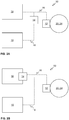
- Figures 2A and 2B illustrate schematically safety systems 50 according to some embodiments of the present invention.
- Figure 2A illustrates the safety controller 10 and the sensor unit 12 which may be configured to generate a first sensor signal indicating a travelling parameter and to provide the first sensor signal to an elevator drive unit 30 of the elevator.
- the signal converter 14 is further shown.
- the signal converter 14 may be connected to the sensor unit 12 and configured to convert the first sensor signal into a second signal in a second format compatible with the safety controller 10.
- the second format of the second signal is, preferably, different than the format of the first sensor signal.
- the signal converter 14 may be further configured to provide the second signal in the second format to the safety controller 10.
- the safety controller 10 may be configured to receive and read the second signal in the second format and to determine, based on the second signal, if there is an emergency condition in the elevator 100.
- the signal converter 14 may be arranged essentially anywhere in the elevator 100 as long as the first sensor signal is arranged to be provided at least to the signal converter 14.
- the signal converter 14 may be implemented by utilizing a circuitry comprising a plurality of electronic components and/or with a programmable logic circuit or programmable processing unit.
- Figure 2B illustrates an embodiment of the safety system 50 which is otherwise similar to the one shown in Fig. 2A except that the signal converter 14 is comprised in the elevator drive unit 30 or at least in a close connection thereto, such as in the same rack for mounting multiple electronic equipment.
- the first sensor signal may be transmitted, preferably essentially unmodified, through the signal converter 14 to the elevator drive unit 30.
- the first sensor signal may be directly provided to the elevator drive unit 30.
- the signal converter 14 may be connected via the first communication channel 16 to the sensor unit 14 and via the second communication channel 18 to the safety controller 10 and, optionally, to some other systems of the elevator 100.
- the other systems may refer to system monitoring the speed of the elevator car 110 and/or the speed of the elevator car 110, or the motor or the traction sheave when the elevator car 110, is close to the ends of the elevator shaft 112.
- the sensor unit 12 may comprise an encoder for producing the first sensor signal, preferably, including information about at least one travelling parameter.
- the sensor unit 12 may comprise a magnetic field sensor. Alternatively, the sensor unit 12 may comprise an inductive proximity sensor.
- the first sensor signal may be arranged to be transmitted via a first communication channel 16 arranged between the sensor unit 12 and the elevator drive unit 30.
- the first sensor signal is an analog signal.
- the second signal may be arranged to be transmitted via a second communication channel 18.
- the format of the second signal is a quadrature encoder signal.
- the first communication channel 16 and the second communication channel 18 may be identical or similar types of channels or, alternatively preferably, different types of channels with respect to each other.
- the first communication channel 16 may be adapted, for example, for utilizing with one of the following sensor technologies, that is to transmit the first signal therefrom: a direct current (DC) tachometer, a resolver, a pulse encoder, such as a rotary encoder, a Sin/Cos encoder.
- the first communication channel 16 may be adapted, for example, for utilizing with one of the following sensor technologies, that is to transmit the first signal therefrom, utilizing serial communication: a Synchronous Serial Interface (SSI) encoder, a bidirectional/serial/synchronous (BiSS) encoder, an Encoder Data (EnDat) encoder.
- SSI Synchronous Serial Interface
- BiSS bidirectional/serial/synchronous
- EnDat Encoder Data
- the second communication channel 16 may be adapted, for example, for utilizing with a data frame format, such as one of the following: an ethernet frame, a Controller Area Network (CAN) bus frame, or a Local Operating Network (LON) bus frame.
- a data frame format such as one of the following: an ethernet frame, a Controller Area Network (CAN) bus frame, or a Local Operating Network (LON) bus frame.
- CAN Controller Area Network
- LON Local Operating Network
- the encoder of the sensor unit 12 may be an SSI encoder. Therefore, in this embodiment, the first sensor signal is of the format, that is the first format, which is suitable for such a synchronous serial communication being in the SSI signal format.
- the signal converter 14 may, optionally, be configured to convert the first format of such synchronous serial communication into a quadrature pulse wave based on the first sensor signal and including information about the travelling parameter indicated by the first sensor signal.
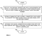
- Figure 3 shows a flow diagram of a method in accordance with an embodiment of the present invention.
- Step 300 refers to a start-up phase of the method. This may in some cases mean shutting down the elevator 100 in order to upgrade the elevator 100 or particularly the safety system 50 thereof.
- Step 310 refers to replacing the present or current sensor unit with a sensor unit 12, that is a new sensor unit 12.
- the sensor unit 12 may be configured to generate a first sensor signal with a first format being different than the second format of the second signal.
- the sensor unit 12 may further be configured to provide the first sensor signal to the elevator drive unit 30.
- Step 320 refers to obtaining or manufacturing a signal converter 14 configured to convert the first sensor signal with the first format into the second signal with the second format.
- Step 330 refers to arranging the signal converter 14 in connection with the sensor unit 12 and to provide the second signal in the second format to the safety controller 10.
- the arranging may comprise arranging the signal converter 14 to or in a close connection with the elevator drive unit 30.
- Method execution may be stopped at step 399.
- the safety system 50 has been upgraded with the new sensor unit 12.
- Advantage of the method is that even though the sensor unit 12 is being replaced there is no need to change the safety controller 14 and, optionally, also the other systems utilizing the measurement data of the sensor unit 12. Furthermore, there is no need to install new sensors for the safety controller 14 and, optionally, also the other systems utilizing the measurement data of the sensor unit 12.
Landscapes
- Engineering & Computer Science (AREA)
- Automation & Control Theory (AREA)
- Computer Networks & Wireless Communication (AREA)
- Structural Engineering (AREA)
- Maintenance And Inspection Apparatuses For Elevators (AREA)
- Indicating And Signalling Devices For Elevators (AREA)
- Elevator Control (AREA)
Abstract
Description
- The present invention relates in general to elevators. In particular, however not exclusively, the present invention concerns a safety system of an elevator, such as configured to be capable of determining an emergency condition of an elevator and preferably further initiating an emergency stop of the elevator.
- Traditionally, elevator drives have many separate sensors and actuators which are general-purpose devices meaning that they are not designed for any specific elevator drive application. Often, they are complicated, expensive, and slow because of many overlapping processing and control functions. Consequently, a separate sensor is needed for each application. The same is true for elevator safety systems.
- An objective of the present invention is to provide a safety system, an elevator, and a method for upgrading a safety system of an elevator. Another objective of the present invention is that the safety system, the elevator, and the method facilitates the operation of the safety system without increasing the amount of sensors for measuring travelling parameters of the elevator, such as related to the operation of the motor and/or traction sheave of the elevator.
- The objectives of the invention are reached by a safety system, an elevator, and a method as defined by the respective independent claims.
- According to a first aspect, a safety system of an elevator. The safety system comprises a safety controller, a sensor unit configured to generate a first sensor signal indicating a travelling parameter and to provide the first sensor signal to an elevator drive unit of the elevator, and a signal converter connected to the sensor unit and configured to convert the first sensor signal into a second signal in a second format compatible with the safety controller and to provide the second signal in the second format to the safety controller. Further, the safety controller is configured to receive the second signal in the second format and to determine, based on the second signal, if there is an emergency condition.
- The travelling parameter of the elevator refers herein to a parameter which is indirectly related to the movement of an elevator car of the elevator. Thus, the travelling parameter may refer to a parameter of the operation of the motor or the traction sheave of the elevator. The travelling parameter may include, for example, at least one of the following: a rotor angle position, a rotating velocity, having a speed and/or a direction, a rotating amount of a traction sheave, an acceleration and/or a deceleration of a traction sheave.
- In various embodiments, the change of format performed by the signal converter means more than merely filtering and/or changing resolution of the first sensor signal. The format change may mean, for example, changing the signal from an analog signal into a digital signal. In various embodiments, the format change may mean actually converting the first sensor signal to be suitable for utilizing in the safety controller and, optionally, some other devices of the elevator.
- In various embodiments, the safety controller may be configured to cause an emergency stop in case of the determination of the emergency condition. For example, the safety controller may be an emergency terminal speed limit controller (ETSL).
- In an embodiment, the safety controller may be configured to compare the travelling parameter carried by the second signal with an emergency stopping criteria, such as related to the speed of the motor, for determining the emergency condition.
- In various embodiments, the sensor unit may comprise an encoder. The encoder may optionally utilize digital, synchronous serial communication technology.
- In some embodiments, the encoder may be a Synchronous Serial Interface (SSI) encoder. Preferably, the first sensor signal may be in SSI signal format.
- In some embodiments, the sensor unit may comprise a magnetic field sensor. Alternatively or in addition, the sensor unit may comprise an inductive proximity sensor.
- In various embodiments, the first sensor signal may be an analog signal.
- In various embodiments, the second signal with the second format is a quadrature signal.
- In some embodiments, the second signal with the second format may be in a data frame format, such as one of the following: an ethernet frame, a Controller Area Network (CAN) bus frame, or a Local Operating Network (LON) bus frame.
- In various embodiments, the signal converter may be arranged to or in a close connection with the elevator drive unit.
- According to a second aspect, an elevator is provided. The elevator comprises an elevator car arranged to be moved in an elevator shaft by a motor of the elevator, and an elevator drive unit arranged to operate the motor. Furthermore, the elevator comprises the safety system according to the first aspect.
- According to a third aspect, a method for upgrading a safety system of an elevator is provided. The safety system comprises, that is prior to the implementation of the method, a present sensor unit arranged in connection with a motor of the elevator and configured to generate a second signal with a second format indicating a travelling parameter and to provide the second signal to an elevator drive unit operating the motor, and a safety controller configured to receive the second signal and to determine, based on the second signal, if there is an emergency condition.
- The method comprises replacing the present sensor unit with a sensor unit, wherein the sensor unit is configured to generate a first sensor signal with a first format being different than the second format. The sensor unit is configured to provide the first sensor signal to the elevator drive unit. The method further comprises obtaining or manufacturing a signal converter configured to convert the first sensor signal with the first format into the second signal with the second format, and arranging the signal converter in connection with the sensor unit and to provide the second signal in the second format to the safety controller.
- In various embodiments, the arranging may comprise arranging the signal converter to or in a close connection with the elevator drive unit.
- The present invention provides a safety system, an elevator, and a method for upgrading a safety system of an elevator. The present invention provides advantages over known solutions in that the number of sensors may be reduced with respect to measuring parameters of the operation of the motor and/or the traction sheave of the elevator with respect to obtaining necessary information for the safety system of the elevator.
- Various other advantages will become clear to a skilled person based on the following detailed description.
- The expression "a plurality of" may refer to any positive integer starting from two (2), that is being at least two.
- The terms "first", "second" and "third" are herein used to distinguish one element from other element, and not to specially prioritize or order them, if not otherwise explicitly stated.
- The exemplary embodiments of the present invention presented herein are not to be interpreted to pose limitations to the applicability of the appended claims. The verb "to comprise" is used herein as an open limitation that does not exclude the existence of also unrecited features. The features recited in depending claims are mutually freely combinable unless otherwise explicitly stated.
- The novel features which are considered as characteristic of the present invention are set forth in particular in the appended claims. The present invention itself, however, both as to its construction and its method of operation, together with additional objectives and advantages thereof, will be best understood from the following description of specific embodiments when read in connection with the accompanying drawings.
- Some embodiments of the invention are illustrated by way of example, and not by way of limitation, in the figures of the accompanying drawings.
-
Figure 1 illustrates schematically an elevator according to an embodiment of the present invention. -
Figures 2A and 2B illustrate schematically safety systems according to some embodiments of the present invention. -
Figure 3 shows a flow diagram of a method in accordance with an embodiment of the present invention. - According to various embodiments of the invention, an elevator safety system may be provided. In particular, the safety system may be an emergency stopping system of an elevator. With this safety system, the number of sensors measuring travelling parameters of an elevator can be reduced without measurement data shortage. Many traditional complicated and expensive components, such as pulse encoders, may be omitted, for instance. In various embodiments, the travelling parameter of the elevator may include at least one of the following: a rotor angle position, a rotating velocity, having a speed and/or a direction, a rotating amount of a traction sheave, an acceleration and/or a deceleration of a traction sheave.
-
Figure 1 illustrates schematically an elevator according to an embodiment of the present invention. Theelevator 100 may comprise anelevator car 110 arranged to be moved in anelevator shaft 112. The moving of theelevator car 110 may be implemented, preferably, by a hoisting rope orbelt 115 in connection with atraction sheave 24 or the like. Furthermore, theelevator 100 may comprise amotor 20 arranged to operate, such as rotate, thetraction sheave 24 for moving theelevator car 110. Thetraction sheave 24 may be connected, via amechanical connection 22, directly or indirectly via a gear to a shaft of themotor 20. Theelevator 100 may comprise a machine room or be machine roomless, such as have themotor 20 in theelevator shaft 112. - The
elevator 100 may preferably comprise at least onehoisting machinery brake 116 configured for resisting or, preferably, preventing the movement of themotor 20, that is the rotor thereof, directly or via the traction sheave 114 or components thereof and/or therebetween when such an action is needed. Especially, the movement may be prevented in an emergency condition of theelevator 100. Furthermore, theelevator 100 may comprise abrake controller 125 configured to operate at least one of the at least onehoisting machinery brake 116. Thebrake controller 125 may further be in connection with other elements of theelevator 100, such as anelevator control unit 1000. Thebrake controller 125 may comprise an actuator (not shown) for operating thebrake 116 or at least be in connection with such an actuating device. - In accordance with various embodiments, and as shown in
Fig. 1 , asafety system 50 of anelevator 100 is presented. Thesafety system 50 may comprise at least asafety controller 10 and asensor unit 12 configured to generate a first sensor signal, for example, in a first format, including information about at least one travelling parameter. Thesensor unit 12 may be adapted for generating the first sensor signal such as to be provided to anelevator drive unit 30 for operating and controlling the operation of themotor 20. Thesafety system 50 preferably further comprises a signal converter (not shown inFig. 1 ) connected to thesensor unit 12 and configured to convert the first sensor signal into a second signal having a second format compatible with thesafety controller 10. Still further, thesafety controller 10 may be configured to receive the second signal in the second format and to determine, based on the second signal, if the conditions are fulfilled to determine an emergency condition of theelevator 100. The second format of the second signal is, preferably, different than the first format of the first sensor signal. - The
elevator control unit 1000 may be configured to control the operation of theelevator 100 in general. This may mean a variety of things as is known to a skilled person in the art of elevators. Theelevator control unit 1000 may be in connection with safety elements and devices, such as a safety chain, of theelevator 100. The elevator control unit may be configured to control the movement of theelevator car 110 in theelevator shaft 112, such as via anelevator drive unit 30. - In various embodiments, the
elevator control unit 1000 may comprise or be at least arranged in connection with thesafety controller 10. - There may additionally be, at least in some embodiments, a
counterweight 118 arranged in connection with theelevator car 110 such as is known to a person skilled in the art of elevators. Still further, theelevator 100 may additionally comprise aguide rail 117 orrails 117 arranged into theelevator shaft 112 for guiding the movement of theelevator car 110. - The
elevator 100 ofFig. 1 further illustrates schematically anelevator drive unit 30, such as including an inverter or a frequency converter, for connecting to, and controlling, by a controller thereof, the operation of, themotor 20. The controller may preferably be configured to operate theelevator drive unit 30 to provide electrical power (signals), such as having variable voltage and/or current, and variable frequency, to themotor 20. The controller may be a separate controller device or be comprised in theelevator drive unit 30, for instance. - In addition, the
elevator 100 may comprise asensor unit 12 arranged in connection with themotor 20 and/or thetraction sheave 24 for determining at least one travelling parameter of theelevator 100, preferably an angle position and/or a rotating speed, and/or an acceleration and/or a deceleration of themotor 20, that is the rotor thereof, or thetraction sheave 24. Thesensor unit 12 is preferably connected to theelevator drive unit 30 for providing a first signal thereto, the first signal being produced by thesensor unit 12 and including information related to the at least one travelling parameter. The first signal may include information about at least one of the following: a rotor angle position, a rotating velocity, having a speed and/or a direction, a rotating amount of a traction sheave, an acceleration and/or a deceleration of a traction sheave; that is of at least one travelling parameter of theelevator 100. - Still further, the
elevator drive unit 30 may be arranged to be fed by an electrical power source, such as of theelevator 100, for example from an external electrical power grid having a fundamental frequency of 50 or 60 Hz, or from another power source, for example, a battery system. Additionally, the electrical power source may intake electrical power from theelevator drive unit 30. - The
elevator 100 preferably comprises landing floors 19 and, for example, landing floor doors and/or openings, between which theelevator car 10 is arranged to be moved during normal operation of theelevator 100, such as to move persons and/or items between said floors 19. -
Figures 2A and 2B illustrate schematicallysafety systems 50 according to some embodiments of the present invention.Figure 2A illustrates thesafety controller 10 and thesensor unit 12 which may be configured to generate a first sensor signal indicating a travelling parameter and to provide the first sensor signal to anelevator drive unit 30 of the elevator. Thesignal converter 14 is further shown. Thesignal converter 14 may be connected to thesensor unit 12 and configured to convert the first sensor signal into a second signal in a second format compatible with thesafety controller 10. The second format of the second signal is, preferably, different than the format of the first sensor signal. Thesignal converter 14 may be further configured to provide the second signal in the second format to thesafety controller 10. Thesafety controller 10 may be configured to receive and read the second signal in the second format and to determine, based on the second signal, if there is an emergency condition in theelevator 100. As also seen inFig. 2A , thesignal converter 14 may be arranged essentially anywhere in theelevator 100 as long as the first sensor signal is arranged to be provided at least to thesignal converter 14. - The
signal converter 14 may be implemented by utilizing a circuitry comprising a plurality of electronic components and/or with a programmable logic circuit or programmable processing unit. -
Figure 2B illustrates an embodiment of thesafety system 50 which is otherwise similar to the one shown inFig. 2A except that thesignal converter 14 is comprised in theelevator drive unit 30 or at least in a close connection thereto, such as in the same rack for mounting multiple electronic equipment. - In some embodiments, for example related to ones in
Fig. 2A and 2B , the first sensor signal may be transmitted, preferably essentially unmodified, through thesignal converter 14 to theelevator drive unit 30. Alternatively, the first sensor signal may be directly provided to theelevator drive unit 30. - As can be seen in
Figs. 2A and 2B , thesignal converter 14 may be connected via thefirst communication channel 16 to thesensor unit 14 and via thesecond communication channel 18 to thesafety controller 10 and, optionally, to some other systems of theelevator 100. In various embodiments, the other systems may refer to system monitoring the speed of theelevator car 110 and/or the speed of theelevator car 110, or the motor or the traction sheave when theelevator car 110, is close to the ends of theelevator shaft 112. - According to various embodiments, the
sensor unit 12 may comprise an encoder for producing the first sensor signal, preferably, including information about at least one travelling parameter. - The
sensor unit 12 may comprise a magnetic field sensor. Alternatively, thesensor unit 12 may comprise an inductive proximity sensor. - In various embodiments, such as related to the ones in
Figs. 2A and 2B , the first sensor signal may be arranged to be transmitted via afirst communication channel 16 arranged between thesensor unit 12 and theelevator drive unit 30. Optionally, the first sensor signal is an analog signal. Additionally, the second signal may be arranged to be transmitted via asecond communication channel 18. Optionally, the format of the second signal is a quadrature encoder signal. Thefirst communication channel 16 and thesecond communication channel 18 may be identical or similar types of channels or, alternatively preferably, different types of channels with respect to each other. - The
first communication channel 16 may be adapted, for example, for utilizing with one of the following sensor technologies, that is to transmit the first signal therefrom: a direct current (DC) tachometer, a resolver, a pulse encoder, such as a rotary encoder, a Sin/Cos encoder. Alternatively, thefirst communication channel 16 may be adapted, for example, for utilizing with one of the following sensor technologies, that is to transmit the first signal therefrom, utilizing serial communication: a Synchronous Serial Interface (SSI) encoder, a bidirectional/serial/synchronous (BiSS) encoder, an Encoder Data (EnDat) encoder. - The
second communication channel 16 may be adapted, for example, for utilizing with a data frame format, such as one of the following: an ethernet frame, a Controller Area Network (CAN) bus frame, or a Local Operating Network (LON) bus frame. - In an embodiment, the encoder of the
sensor unit 12 may be an SSI encoder. Therefore, in this embodiment, the first sensor signal is of the format, that is the first format, which is suitable for such a synchronous serial communication being in the SSI signal format. Thesignal converter 14 may, optionally, be configured to convert the first format of such synchronous serial communication into a quadrature pulse wave based on the first sensor signal and including information about the travelling parameter indicated by the first sensor signal. -
Figure 3 shows a flow diagram of a method in accordance with an embodiment of the present invention. - Step 300 refers to a start-up phase of the method. This may in some cases mean shutting down the
elevator 100 in order to upgrade theelevator 100 or particularly thesafety system 50 thereof. - Step 310 refers to replacing the present or current sensor unit with a
sensor unit 12, that is anew sensor unit 12. Thesensor unit 12 may be configured to generate a first sensor signal with a first format being different than the second format of the second signal. Thesensor unit 12 may further be configured to provide the first sensor signal to theelevator drive unit 30. - Step 320 refers to obtaining or manufacturing a
signal converter 14 configured to convert the first sensor signal with the first format into the second signal with the second format. - Step 330 refers to arranging the
signal converter 14 in connection with thesensor unit 12 and to provide the second signal in the second format to thesafety controller 10. In some embodiments, the arranging may comprise arranging thesignal converter 14 to or in a close connection with theelevator drive unit 30. - Method execution may be stopped at
step 399. Thesafety system 50 has been upgraded with thenew sensor unit 12. - Advantage of the method is that even though the
sensor unit 12 is being replaced there is no need to change thesafety controller 14 and, optionally, also the other systems utilizing the measurement data of thesensor unit 12. Furthermore, there is no need to install new sensors for thesafety controller 14 and, optionally, also the other systems utilizing the measurement data of thesensor unit 12.
Claims (15)
- A safety system (50) of an elevator (100), comprising:a safety controller (10);a sensor unit (12) configured to generate a first sensor signal indicating a travelling parameter and to provide the first sensor signal to an elevator drive unit (30) of the elevator (100); characterized in that the safety system comprisesa signal converter (14) connected to the sensor unit (12) and configured to convert the first sensor signal into a second signal in a second format compatible with the safety controller (10) and to provide the second signal in the second format to the safety controller (10),wherein the safety controller (10) is configured to receive the second signal in the second format and to determine, based on the second signal, if there is an emergency condition.
- The safety system (50) according to claim 1, wherein safety controller (10) is configured to compare the travelling parameter carried by the second signal with an emergency stopping criteria for determining the emergency condition.
- The safety system (50) according to claim 1 or 2, wherein safety controller (10) is configured to cause an emergency stop in case of the determination of the emergency condition.
- The safety system (50) according to any one of claims 1-3, wherein the safety controller (10) is an emergency terminal speed limit controller.
- The safety system (50) according to any one of claims 1-4, wherein an encoder of the sensor unit (12) is a Synchronous Serial Interface encoder.
- The safety system (50) according to any one of claims 1-5, wherein the sensor unit (12) comprises a magnetic field sensor.
- The safety system (50) according to any one of claims 1-5, wherein the sensor unit (12) comprises an inductive proximity sensor.
- The safety system (50) according to any one of claims 1-7, wherein the first sensor signal is in Synchronous Serial Interface signal format.
- The safety system (50) according to any one of claims 1-8, wherein the first sensor signal is an analog signal.
- The safety system (50) according to any one of claims 1-9, wherein the second signal with the second format is a quadrature signal.
- The safety system (50) according to any one of claims 1-10, wherein the second signal with the second format is in a data frame format, such as one of the following: an ethernet frame, a Controller Area Network bus frame, or a Local Operating Network bus frame.
- The safety system (50) according to any one of claims 1-11, wherein the signal converter is arranged to or in a close connection with the elevator drive unit (30).
- An elevator (100) comprising an elevator car (110) arranged to be moved in an elevator shaft (112) by a motor (20) of the elevator (100), and an elevator drive unit (30) arranged to operate the motor (20), characterized in that the elevator (100) comprises the safety system (50) according to any one of claims 1-12.
- A method for upgrading a safety system (50) of an elevator (100), wherein the safety system (50) comprises a present sensor unit arranged in connection with a motor (20) of the elevator (100) and configured to generate a second signal with a second format indicating a travelling parameter and to provide the second signal to an elevator drive unit (30) operating the motor (20), and a safety controller (10) configured to receive the second signal and to determine, based on the second signal, if there is an emergency condition, wherein the method comprises:
replacing (310) the present sensor unit with a sensor unit (12), wherein the sensor unit (12) is configured to generate a first sensor signal with a first format being different than the second format, configured to provide the first sensor signal to the elevator drive unit (30),
characterized in that the method further comprises:obtaining or manufacturing (320) a signal converter (14) configured to convert the first sensor signal with the first format into the second signal with the second format, andarranging (330) the signal converter (14) in connection with the sensor unit (12) and to provide the second signal in the second format to the safety controller (10). - The method of claim 14, wherein the arranging comprises arranging the signal converter (14) to or in a close connection with the elevator drive unit (30).
Priority Applications (6)
| Application Number | Priority Date | Filing Date | Title |
|---|---|---|---|
| FIEP20168465.1T FI3892582T3 (en) | 2020-04-07 | 2020-04-07 | ELEVATOR |
| DK20168465.1T DK3892582T3 (en) | 2020-04-07 | 2020-04-07 | Elevator |
| EP20168465.1A EP3892582B1 (en) | 2020-04-07 | 2020-04-07 | Elevator |
| US17/218,851 US20210309487A1 (en) | 2020-04-07 | 2021-03-31 | Safety system, elevator, and method for upgrading a safety system of an elevator |
| AU2021202046A AU2021202046A1 (en) | 2020-04-07 | 2021-04-01 | Safety system, elevator, and method for upgrading a safety system of an elevator |
| CN202110367652.9A CN113493152B (en) | 2020-04-07 | 2021-04-06 | Safety system, elevator and method for upgrading a safety system of an elevator |
Applications Claiming Priority (1)
| Application Number | Priority Date | Filing Date | Title |
|---|---|---|---|
| EP20168465.1A EP3892582B1 (en) | 2020-04-07 | 2020-04-07 | Elevator |
Publications (2)
| Publication Number | Publication Date |
|---|---|
| EP3892582A1 true EP3892582A1 (en) | 2021-10-13 |
| EP3892582B1 EP3892582B1 (en) | 2026-01-28 |
Family
ID=70227848
Family Applications (1)
| Application Number | Title | Priority Date | Filing Date |
|---|---|---|---|
| EP20168465.1A Active EP3892582B1 (en) | 2020-04-07 | 2020-04-07 | Elevator |
Country Status (6)
| Country | Link |
|---|---|
| US (1) | US20210309487A1 (en) |
| EP (1) | EP3892582B1 (en) |
| CN (1) | CN113493152B (en) |
| AU (1) | AU2021202046A1 (en) |
| DK (1) | DK3892582T3 (en) |
| FI (1) | FI3892582T3 (en) |
Families Citing this family (1)
| Publication number | Priority date | Publication date | Assignee | Title |
|---|---|---|---|---|
| WO2017168035A1 (en) * | 2016-03-30 | 2017-10-05 | Kone Corporation | A method, a safety control unit, and an elevator system for verifying speed data of an elevator car for overspeed monitoring of the elevator car |
Citations (3)
| Publication number | Priority date | Publication date | Assignee | Title |
|---|---|---|---|---|
| EP1864934A1 (en) * | 2005-03-31 | 2007-12-12 | Mitsubishi Denki Kabushiki Kaisha | Elevator apparatus |
| WO2010150644A1 (en) * | 2009-06-23 | 2010-12-29 | 三菱電機株式会社 | Elevator device |
| WO2018059944A1 (en) * | 2016-09-29 | 2018-04-05 | Inventio Ag | Car and entity safety supervising unit for an elevator |
Family Cites Families (13)
| Publication number | Priority date | Publication date | Assignee | Title |
|---|---|---|---|---|
| JPS50113957A (en) * | 1974-02-21 | 1975-09-06 | ||
| JPH04153176A (en) * | 1990-10-16 | 1992-05-26 | Mitsubishi Electric Corp | Monitor and control unit for elevator |
| KR100218404B1 (en) * | 1997-08-30 | 1999-09-01 | 이종수 | Rescue operation method using motor drive controller |
| US6854010B1 (en) * | 2001-04-05 | 2005-02-08 | Bluecube Software, Inc. | Multi-location management system |
| US20090014256A1 (en) * | 2004-04-06 | 2009-01-15 | Mitsubishi Denki Kabushiki Kaisha | Elevator Apparatus and Method of Controlling the Apparatus |
| EP2848568B1 (en) * | 2013-09-17 | 2022-07-20 | KONE Corporation | A method and an elevator for stopping an elevator car using elevator drive |
| US10144613B2 (en) * | 2014-05-21 | 2018-12-04 | Mitsubishi Electric Corporation | Elevator position detection apparatus |
| US20180150806A1 (en) * | 2014-10-14 | 2018-05-31 | Xicore Inc. | Systems for Actively Monitoring Lift Devices and Maintaining Lift Devices, and Related Methods |
| WO2016096015A1 (en) * | 2014-12-18 | 2016-06-23 | Kone Corporation | System for the generation of call advance data |
| JP6173653B2 (en) * | 2015-06-15 | 2017-08-02 | 三菱電機株式会社 | Elevator safety system |
| DK3403971T3 (en) * | 2017-05-19 | 2021-01-25 | Kone Corp | PROCEDURE FOR PERFORMING A MANUAL DRIVE IN AN ELEVATOR AFTER POWER DISCONNECTION |
| CN110799436B (en) * | 2017-06-27 | 2022-06-17 | 因温特奥股份公司 | Position determination system and method for determining the position of a car of an elevator car |
| JP6601587B1 (en) * | 2019-07-26 | 2019-11-06 | フジテック株式会社 | Elevator encoder diagnostic system and diagnostic method |
-
2020
- 2020-04-07 DK DK20168465.1T patent/DK3892582T3/en active
- 2020-04-07 EP EP20168465.1A patent/EP3892582B1/en active Active
- 2020-04-07 FI FIEP20168465.1T patent/FI3892582T3/en active
-
2021
- 2021-03-31 US US17/218,851 patent/US20210309487A1/en active Pending
- 2021-04-01 AU AU2021202046A patent/AU2021202046A1/en active Pending
- 2021-04-06 CN CN202110367652.9A patent/CN113493152B/en active Active
Patent Citations (3)
| Publication number | Priority date | Publication date | Assignee | Title |
|---|---|---|---|---|
| EP1864934A1 (en) * | 2005-03-31 | 2007-12-12 | Mitsubishi Denki Kabushiki Kaisha | Elevator apparatus |
| WO2010150644A1 (en) * | 2009-06-23 | 2010-12-29 | 三菱電機株式会社 | Elevator device |
| WO2018059944A1 (en) * | 2016-09-29 | 2018-04-05 | Inventio Ag | Car and entity safety supervising unit for an elevator |
Also Published As
| Publication number | Publication date |
|---|---|
| DK3892582T3 (en) | 2026-04-07 |
| CN113493152B (en) | 2026-03-10 |
| US20210309487A1 (en) | 2021-10-07 |
| AU2021202046A1 (en) | 2021-10-21 |
| EP3892582B1 (en) | 2026-01-28 |
| CN113493152A (en) | 2021-10-12 |
| FI3892582T3 (en) | 2026-04-16 |
Similar Documents
| Publication | Publication Date | Title |
|---|---|---|
| EP3599200B1 (en) | Elevator | |
| RU2369554C2 (en) | Monitoring lift status | |
| US11440776B2 (en) | Monitoring solution for a conveyor system | |
| CN101151200A (en) | Elevator System Arrangement | |
| CN103079981A (en) | Elevator safety system and method | |
| EP2252538B1 (en) | Safety arrangement of a transport system | |
| EP3892582B1 (en) | Elevator | |
| CN101336203B (en) | Encoder Fault Management in Elevator Drive System | |
| EP1864934A1 (en) | Elevator apparatus | |
| CN113716410A (en) | Elevator safety monitoring system, elevator and method for operating elevator | |
| HK40056208A (en) | Safety system, elevator, and method for upgrading a safety system of an elevator | |
| US12139374B2 (en) | Method and device for monitoring an elevator system | |
| JP3149416B2 (en) | Elevator hoist | |
| US20250026609A1 (en) | Elevator system and a method | |
| WO2020245495A1 (en) | Control of an elevator system | |
| WO2025229249A1 (en) | An elevator safety monitoring system and method | |
| WO2025002578A1 (en) | Method, elevator control unit, and elevator system for elevator car speed monitoring | |
| HK40022610A (en) | Elevator | |
| HK40022610B (en) | Elevator | |
| CN116601100A (en) | Safety concept for elevators | |
| HK40035069B (en) | A monitoring solution for a conveyor system | |
| HK1153445A1 (en) | Elevator with highly electronic safety device | |
| HK1153445B (en) | Elevator with highly electronic safety device | |
| HK1111669A (en) | Elevator arrangement |
Legal Events
| Date | Code | Title | Description |
|---|---|---|---|
| PUAI | Public reference made under article 153(3) epc to a published international application that has entered the european phase |
Free format text: ORIGINAL CODE: 0009012 |
|
| STAA | Information on the status of an ep patent application or granted ep patent |
Free format text: STATUS: THE APPLICATION HAS BEEN PUBLISHED |
|
| AK | Designated contracting states |
Kind code of ref document: A1 Designated state(s): AL AT BE BG CH CY CZ DE DK EE ES FI FR GB GR HR HU IE IS IT LI LT LU LV MC MK MT NL NO PL PT RO RS SE SI SK SM TR |
|
| STAA | Information on the status of an ep patent application or granted ep patent |
Free format text: STATUS: REQUEST FOR EXAMINATION WAS MADE |
|
| 17P | Request for examination filed |
Effective date: 20220411 |
|
| RBV | Designated contracting states (corrected) |
Designated state(s): AL AT BE BG CH CY CZ DE DK EE ES FI FR GB GR HR HU IE IS IT LI LT LU LV MC MK MT NL NO PL PT RO RS SE SI SK SM TR |
|
| P01 | Opt-out of the competence of the unified patent court (upc) registered |
Effective date: 20230525 |
|
| STAA | Information on the status of an ep patent application or granted ep patent |
Free format text: STATUS: EXAMINATION IS IN PROGRESS |
|
| 17Q | First examination report despatched |
Effective date: 20230809 |
|
| GRAP | Despatch of communication of intention to grant a patent |
Free format text: ORIGINAL CODE: EPIDOSNIGR1 |
|
| STAA | Information on the status of an ep patent application or granted ep patent |
Free format text: STATUS: GRANT OF PATENT IS INTENDED |
|
| INTG | Intention to grant announced |
Effective date: 20250820 |
|
| GRAS | Grant fee paid |
Free format text: ORIGINAL CODE: EPIDOSNIGR3 |
|
| GRAA | (expected) grant |
Free format text: ORIGINAL CODE: 0009210 |
|
| STAA | Information on the status of an ep patent application or granted ep patent |
Free format text: STATUS: THE PATENT HAS BEEN GRANTED |
|
| AK | Designated contracting states |
Kind code of ref document: B1 Designated state(s): AL AT BE BG CH CY CZ DE DK EE ES FI FR GB GR HR HU IE IS IT LI LT LU LV MC MK MT NL NO PL PT RO RS SE SI SK SM TR |
|
| REG | Reference to a national code |
Ref country code: CH Ref legal event code: F10 Free format text: ST27 STATUS EVENT CODE: U-0-0-F10-F00 (AS PROVIDED BY THE NATIONAL OFFICE) Effective date: 20260128 Ref country code: GB Ref legal event code: FG4D |
|
| REG | Reference to a national code |
Ref country code: DE Ref legal event code: R096 Ref document number: 602020065762 Country of ref document: DE |
|
| REG | Reference to a national code |
Ref country code: IE Ref legal event code: FG4D |
|
| REG | Reference to a national code |
Ref country code: DK Ref legal event code: T3 Effective date: 20260331 |
|
| REG | Reference to a national code |
Ref country code: FI Ref legal event code: FGE |