EP3892571A1 - Reversible bucket elevator - Google Patents
Reversible bucket elevator Download PDFInfo
- Publication number
- EP3892571A1 EP3892571A1 EP21020174.5A EP21020174A EP3892571A1 EP 3892571 A1 EP3892571 A1 EP 3892571A1 EP 21020174 A EP21020174 A EP 21020174A EP 3892571 A1 EP3892571 A1 EP 3892571A1
- Authority
- EP
- European Patent Office
- Prior art keywords
- bucket
- tipping
- conveyor
- reversible
- stretch
- Prior art date
- Legal status (The legal status is an assumption and is not a legal conclusion. Google has not performed a legal analysis and makes no representation as to the accuracy of the status listed.)
- Granted
Links
Images



Classifications
-
- B—PERFORMING OPERATIONS; TRANSPORTING
- B65—CONVEYING; PACKING; STORING; HANDLING THIN OR FILAMENTARY MATERIAL
- B65G—TRANSPORT OR STORAGE DEVICES, e.g. CONVEYORS FOR LOADING OR TIPPING, SHOP CONVEYOR SYSTEMS OR PNEUMATIC TUBE CONVEYORS
- B65G17/00—Conveyors having an endless traction element, e.g. a chain, transmitting movement to a continuous or substantially-continuous load-carrying surface or to a series of individual load-carriers; Endless-chain conveyors in which the chains form the load-carrying surface
- B65G17/16—Conveyors having an endless traction element, e.g. a chain, transmitting movement to a continuous or substantially-continuous load-carrying surface or to a series of individual load-carriers; Endless-chain conveyors in which the chains form the load-carrying surface comprising individual load-carriers which are pivotally mounted, e.g. for free-swinging movement
-
- B—PERFORMING OPERATIONS; TRANSPORTING
- B65—CONVEYING; PACKING; STORING; HANDLING THIN OR FILAMENTARY MATERIAL
- B65G—TRANSPORT OR STORAGE DEVICES, e.g. CONVEYORS FOR LOADING OR TIPPING, SHOP CONVEYOR SYSTEMS OR PNEUMATIC TUBE CONVEYORS
- B65G47/00—Article or material-handling devices associated with conveyors; Methods employing such devices
- B65G47/34—Devices for discharging articles or materials from conveyor
- B65G47/38—Devices for discharging articles or materials from conveyor by dumping, tripping, or releasing load carriers
- B65G47/40—Devices for discharging articles or materials from conveyor by dumping, tripping, or releasing load carriers by tilting conveyor buckets
-
- B—PERFORMING OPERATIONS; TRANSPORTING
- B65—CONVEYING; PACKING; STORING; HANDLING THIN OR FILAMENTARY MATERIAL
- B65G—TRANSPORT OR STORAGE DEVICES, e.g. CONVEYORS FOR LOADING OR TIPPING, SHOP CONVEYOR SYSTEMS OR PNEUMATIC TUBE CONVEYORS
- B65G17/00—Conveyors having an endless traction element, e.g. a chain, transmitting movement to a continuous or substantially-continuous load-carrying surface or to a series of individual load-carriers; Endless-chain conveyors in which the chains form the load-carrying surface
- B65G17/12—Conveyors having an endless traction element, e.g. a chain, transmitting movement to a continuous or substantially-continuous load-carrying surface or to a series of individual load-carriers; Endless-chain conveyors in which the chains form the load-carrying surface comprising a series of individual load-carriers fixed, or normally fixed, relative to traction element
- B65G17/126—Bucket elevators
Definitions
- the present invention belongs to the technical field of bucket elevators, which comprise a frame with an endless inner lift conveyor to which there are coupled a plurality of buckets apt to contain and lift a load to a higher unloading area and which presents tipping means for said buckets.
- bucket elevators based on parallel endless chains with buckets coupled thereto and that allow transport and lifting of a certain product to dispose it at a higher point are very much used within a production process.
- the buckets are configured to keep a horizontal position that allows the safe transport of the product and its coupling to the transporting chains must be such that given the moment when the bucket reaches the unloading area, it is possible the controlled tipping thereof to accomplish the product unloading.
- the buckets were designed with asymmetric configurations that facilitated the unloading in one sense, i.e., that for which it was designed and thus, in principle, this made impossible a possible change of sense of direction in the production line.
- the reference document H05213425 proposes a bucket elevator for its use in material handling, wherein the buckets present as an improvement a spoon shape that allows the bidirectional conveyance thereof. More specifically, this invention provides a method of unloading a spoon-bucket when the device is advancing as well as when the device is reversing, whereas a seal is kept between adjacent spoon-buckets in the moment of loading, to avoid material loss.
- said bucket is based in the contact of an element of the bucket with an obstacle located in its path to cause the tipping thereof, but because it is an asymmetric bucket, it requires the location of two obstacles to activate the tipping in each sense of movement, respectively.
- the second reference document US4009531 defines a bucket wheel or apparatus to pick up bulk materials, consisting of a plurality of buckets mounted on a mobile endless support, such as a wheel, that comprises an actuating device that allows the propulsion thereof in opposite directions.
- Each bucket consists of a structure with two apertures that can pivot about a rotation axis and present two final tipping positions.
- Each aperture of the bucket assembly is located in active or inactive position automatically and without staff intervention. When the wheel turns, the buckets collide with the material heap and the resistance of the products automatically leads the bucket to the active position, i.e., the receiving aperture facing the material is open at its maximum.
- the tipping is accomplished by gravity.
- the material is loaded through an aperture or through the other. It is oriented for the specific case of a transport wheel, such that is offers no solution to the case of linear bucket elevators in which the load must be lifted until a certain height and unload it in a determined area.
- this defines a reversible bucket for proofing chambers for bakeable doughs. It refers to an oscillating bucket system formed by a flexible fabric sleeve, which does not require any guiding device along its path inside the chamber, except in the unloading station in which the bucket must be tipped.
- the bucket system requires a pushing mechanism in one sense or the other in order to cause the bucket tipping in the unloading area, although the document does not specify said mechanism. Nevertheless, it is clear that several additional elements are needed, which complicates the facility.
- the reversible bucket elevator herein presented, comprises a frame with at least a first stretch with a first and second ends, wherein the second end is located at a higher point than the first end and which interior presents an endless lifting conveyor to which a plurality of buckets are coupled, the buckets being apt to contain and lift the load, with at least an unloading area that presents tipping means of said buckets.
- each bucket is formed by a concave symmetrical body with an upper open end, both connection sides to the conveyor, equal and parallel between them, and both sides opposed to each other located between the connection sides.
- each bucket comprises coupling means to the conveyor formed by a connecting shaft located in the symmetry axis of the connecting sides, proximal to the upper bucket end and, means for adjusting to the tipping means.
- Said means for adjusting to the tipping means are formed by a contact guide located in the connection sides, which exhibits an ellipse shape whose major axis is located in the symmetry axis of the connection sides, with a first end proximal to the bucket upper end, and a second opposing end, wherein the buckets connecting shaft is contained in said major ellipse axis.
- the tipping means are formed by a longitudinal element parallel to the conveyor with a surface facing the same that exhibits a curved symmetric and convex towards the conveyor profile, with an active tipping position such that the contact of a bucket guide with said curved profile, in both senses of bucket advancement, generates a progressive tipping thereof in the sense of advancement, until reaching a bucket maximum tipping in the central area of said curved profile.
- the bucket elevator herein proposed comprises a frame (3) which presents at least a first stretch (1) with a first and second ends, wherein the second end (1.1) is located at a higher point than the first end and in which interior presents an endless lifting conveyor (4) to which there are coupled a plurality of buckets (5) apt to contain and lift a load, with at least an unloading area that presents said buckets (5) tipping means.
- the bucket elevator comprises at least two end drums, being a first drum (not shown in the Figures) located in the first end of the first stretch (1) and a second drum (6) arranged at the second end (1.1) thereof, wherein both first and second drums are connected by means of the conveyor (4) and at least one of them is connected to rotation means.
- this bucket elevator comprises a second stretch (2), located following the first stretch (1) and forming an angle therewith, which is 90° in this case, being in this case the first stretch (1) vertical and the second stretch (2) horizontal and, presents a third drum (7) arranged at the end (2.1) of said second stretch (2), as shown in Figure 1 .
- the first stretch (1) thereof presents a second additional drum (8) in the second end (1.1) of the first stretch (1), In order to be able to close the endless conveyor (4) around said first and second stretches (1, 2).
- each bucket (5) is formed by a concave symmetric body with an open upper end (9), two connection sides (10) to the conveyor, equal and parallel between them and two sides (11) opposed to each other and located between the connection sides (10).
- each bucket (5) comprises coupling means to the conveyor formed by a connecting shaft (12) located in the symmetry axis of the connection sides (10), proximal to the upper end (9) of the bucket (5).
- each bucket (5) comprises means for adjusting to the tipping means formed by a guide (13) located on the connection sides, which presents an ellipse shape whose major axis is located in the symmetry axis of the connection sides (10), with a first end (13.1) proximal to the upper bucket (5) end (9) and an opposite second end (13.2), wherein the bucket (5) connecting shaft (12) is contained in the ellipse major axis.
- the tipping means are formed by a longitudinal element (14) parallel to the conveyor (4) with a surface oriented towards said conveyor (4) that presents a curved symmetric and convex to said conveyor (4) profile (15).
- This tipping means present an active tipping position such that the contact of a bucket guide (13) with said curved profile (15), in both bucket (5) advancement senses, generates a progressive tipping thereof in the advancement sense, until reaching a bucket (5) maximum tipping in the central area (14.1) of said curved profile (15).
- the curved profile (15) of the tipping means presents a separation distance to the bucket (5) connecting shaft (12) that, in its ends (14.2) is equal or greater than the distance between said connecting shaft (12) and the second end (13.2) of the major guide (13) axis and, in the central area (14.1) of said curved profile (15), is less than half of the said guide (13) minor axis.
- the longitudinal element (14) is located proximal to the end (2.1) of the second stretch (2) of the conveyor (4), but in other embodiments it may be located in any area of the second stretch (2) or of the first stretch (1), always arranging the curved profile (15) of the longitudinal element (14) oriented towards the conveyor (14).
- connection sides (12) present a frustoconical section.
- the bucket elevator comprises at least two unloading areas. More specifically, as it is shown in Figure 4 , it comprises three unloading areas, with corresponding tipping means in each one, i.e., a first, second and third tipping means (V1, V2, V3).
- Said tipping means present activation/deactivation means formed by a displacement mechanism thereof with respect of the frame (3) from the active position in which there is contact of the curved profile 915) with the bucket (5) guide (13) until a passive position in which the tipping means are arranged further away from the conveyor (4), thus avoiding the contact thereof with the bucket (5) guide (13).
- first and third tipping means (V1, V3) are in a passive position and there is no contact of the curved profile (15) of the longitudinal element (14) thereof with the bucket (5) guide (13), whereas in the second tipping means (V2) are in an active position in which there is contact and therefore the buckets (5) tipping is caused upon passing along said unloading area.
- the displacement mechanism (16) of the tipping means comprises a mechanical actuator, specifically a pneumatic actuator. In other embodiments it may be an electric actuator, by spindle or any other similar one. Likewise, in other embodiments said displacement mechanism (16) of the tipping means may comprise a manual actuator.
Landscapes
- Engineering & Computer Science (AREA)
- Mechanical Engineering (AREA)
- Chain Conveyers (AREA)
- Specific Conveyance Elements (AREA)
- Forklifts And Lifting Vehicles (AREA)
Abstract
Description
- The present invention belongs to the technical field of bucket elevators, which comprise a frame with an endless inner lift conveyor to which there are coupled a plurality of buckets apt to contain and lift a load to a higher unloading area and which presents tipping means for said buckets.
- Nowadays bucket elevators based on parallel endless chains with buckets coupled thereto and that allow transport and lifting of a certain product to dispose it at a higher point are very much used within a production process.
- The buckets are configured to keep a horizontal position that allows the safe transport of the product and its coupling to the transporting chains must be such that given the moment when the bucket reaches the unloading area, it is possible the controlled tipping thereof to accomplish the product unloading.
- In the daily operation and practice in the production facilities, there are situations in which it is required a change in the buckets' sense of direction in order to fulfil operations of filling and unloading or to modifications on the sense of direction due to restructuring of the product organization.
- Initially, the buckets were designed with asymmetric configurations that facilitated the unloading in one sense, i.e., that for which it was designed and thus, in principle, this made impossible a possible change of sense of direction in the production line.
- In order to adapt to the new necessities that were required, some buckets appeared that opened the possibility to change in the sense of advancement of the lines, although they still present drawbacks, given that they require new elements that allow the change of sense and the correct bucket tipping in both senses of advancement. In many occasions they need human intervention so as to reverse the buckets and, in any case, the results are more complex lines and mechanisms.
- As an example of the state-of-the-art, the following reference documents can be mentioned
H05213425 US4009531 andES225902 - The reference document
H05213425 - Nevertheless, the functioning of said bucket is based in the contact of an element of the bucket with an obstacle located in its path to cause the tipping thereof, but because it is an asymmetric bucket, it requires the location of two obstacles to activate the tipping in each sense of movement, respectively.
- This way of proceeding complicates the installation and makes it compulsory to provide a different unloading area depending on the sense of advancement of the buckets, thus requiring the facility to comprise duplicated receiving means.
- The second reference document
US4009531 defines a bucket wheel or apparatus to pick up bulk materials, consisting of a plurality of buckets mounted on a mobile endless support, such as a wheel, that comprises an actuating device that allows the propulsion thereof in opposite directions. - Each bucket consists of a structure with two apertures that can pivot about a rotation axis and present two final tipping positions. Each aperture of the bucket assembly is located in active or inactive position automatically and without staff intervention. When the wheel turns, the buckets collide with the material heap and the resistance of the products automatically leads the bucket to the active position, i.e., the receiving aperture facing the material is open at its maximum.
- Even though the bucket here is symmetric, the tipping is accomplished by gravity. Depending on the sense of the wheel turning, the material is loaded through an aperture or through the other. It is oriented for the specific case of a transport wheel, such that is offers no solution to the case of linear bucket elevators in which the load must be lifted until a certain height and unload it in a determined area.
- In the case of reference document
ES225902 - In this case, the bucket system requires a pushing mechanism in one sense or the other in order to cause the bucket tipping in the unloading area, although the document does not specify said mechanism. Nevertheless, it is clear that several additional elements are needed, which complicates the facility.
- It is not known in the state-of-the-art any bucket elevator that allows the change on the sense of advancement thereof without implying complications in the facility or previous manual modifications and that allows a similar operation in both senses.
- The reversible bucket elevator herein presented, comprises a frame with at least a first stretch with a first and second ends, wherein the second end is located at a higher point than the first end and which interior presents an endless lifting conveyor to which a plurality of buckets are coupled, the buckets being apt to contain and lift the load, with at least an unloading area that presents tipping means of said buckets.
- In this elevator, each bucket is formed by a concave symmetrical body with an upper open end, both connection sides to the conveyor, equal and parallel between them, and both sides opposed to each other located between the connection sides.
- Furthermore, each bucket comprises coupling means to the conveyor formed by a connecting shaft located in the symmetry axis of the connecting sides, proximal to the upper bucket end and, means for adjusting to the tipping means.
- Said means for adjusting to the tipping means are formed by a contact guide located in the connection sides, which exhibits an ellipse shape whose major axis is located in the symmetry axis of the connection sides, with a first end proximal to the bucket upper end, and a second opposing end, wherein the buckets connecting shaft is contained in said major ellipse axis.
- Likewise, in this bucket elevator, the tipping means are formed by a longitudinal element parallel to the conveyor with a surface facing the same that exhibits a curved symmetric and convex towards the conveyor profile, with an active tipping position such that the contact of a bucket guide with said curved profile, in both senses of bucket advancement, generates a progressive tipping thereof in the sense of advancement, until reaching a bucket maximum tipping in the central area of said curved profile.
- With the bucket elevator herein proposed a significant improvement of the state-of-the-art is achieved.
- This is because a solution is achieved in which the bucket elevator allows a reversible operation thereof, i.e., in an advancement sense or in the opposite sense, to be able to adapt to the production demands thus increasing the efficacy of the process.
- This reversibility is achieved is a simple way and without needing auxiliary elements or facilities, given that thanks to the buckets' symmetry and to the elliptic shape of the means for adjusting to the tipping means, also symmetrical, the tipping is accomplished in the same unloading area in both senses of advancement and with the same tipping means. This significantly simplifies the facility and favours a fluid operation in both senses, with a great effectivity and a cost reduction.
- In order to aid to a better understanding of the invention features, according to a preferred realisation example thereof, there is provided as integral part of said description, a series of drawings wherein, with illustrative and non-limiting character, the following has been represented:
-
Figure 1 .- Shows a schematic sectional view of a bucket elevator, for a preferred embodiment of the invention. -
Figure 2 .- Shows a view of detail A ofFigure 1 . -
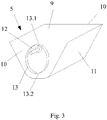
Figure 3 .- Shows a perspective view of a bucket, for a preferred embodiment of the invention. - In the view of the figures provided, it can be observed how, in a preferred embodiment of the invention, the bucket elevator herein proposed comprises a frame (3) which presents at least a first stretch (1) with a first and second ends, wherein the second end (1.1) is located at a higher point than the first end and in which interior presents an endless lifting conveyor (4) to which there are coupled a plurality of buckets (5) apt to contain and lift a load, with at least an unloading area that presents said buckets (5) tipping means.
- In this preferred embodiment of the invention, as shown in
Figure 1 , the bucket elevator comprises at least two end drums, being a first drum (not shown in the Figures) located in the first end of the first stretch (1) and a second drum (6) arranged at the second end (1.1) thereof, wherein both first and second drums are connected by means of the conveyor (4) and at least one of them is connected to rotation means. - Furthermore, this bucket elevator comprises a second stretch (2), located following the first stretch (1) and forming an angle therewith, which is 90° in this case, being in this case the first stretch (1) vertical and the second stretch (2) horizontal and, presents a third drum (7) arranged at the end (2.1) of said second stretch (2), as shown in
Figure 1 . - By having this elevator this second stretch (2), the first stretch (1) thereof presents a second additional drum (8) in the second end (1.1) of the first stretch (1), In order to be able to close the endless conveyor (4) around said first and second stretches (1, 2).
- In the reversible bucket elevator herein presented, each bucket (5) is formed by a concave symmetric body with an open upper end (9), two connection sides (10) to the conveyor, equal and parallel between them and two sides (11) opposed to each other and located between the connection sides (10).
- As it can be observed in
Figures 2 and3 , each bucket (5) comprises coupling means to the conveyor formed by a connecting shaft (12) located in the symmetry axis of the connection sides (10), proximal to the upper end (9) of the bucket (5). - Likewise, each bucket (5) comprises means for adjusting to the tipping means formed by a guide (13) located on the connection sides, which presents an ellipse shape whose major axis is located in the symmetry axis of the connection sides (10), with a first end (13.1) proximal to the upper bucket (5) end (9) and an opposite second end (13.2), wherein the bucket (5) connecting shaft (12) is contained in the ellipse major axis.
- On another side, as shown in
Figure 2 , the tipping means are formed by a longitudinal element (14) parallel to the conveyor (4) with a surface oriented towards said conveyor (4) that presents a curved symmetric and convex to said conveyor (4) profile (15). - This tipping means present an active tipping position such that the contact of a bucket guide (13) with said curved profile (15), in both bucket (5) advancement senses, generates a progressive tipping thereof in the advancement sense, until reaching a bucket (5) maximum tipping in the central area (14.1) of said curved profile (15).
- In this preferred embodiment of the invention, the curved profile (15) of the tipping means presents a separation distance to the bucket (5) connecting shaft (12) that, in its ends (14.2) is equal or greater than the distance between said connecting shaft (12) and the second end (13.2) of the major guide (13) axis and, in the central area (14.1) of said curved profile (15), is less than half of the said guide (13) minor axis.
- In this preferred embodiment of the invention, as shown in
Figures 1 and2 , the longitudinal element (14) is located proximal to the end (2.1) of the second stretch (2) of the conveyor (4), but in other embodiments it may be located in any area of the second stretch (2) or of the first stretch (1), always arranging the curved profile (15) of the longitudinal element (14) oriented towards the conveyor (14). - As it is shown in
Figure 1 , the bucket (5) connection sides (12) present a frustoconical section. - In this memory it is proposed a second embodiment in which, contrarily to the first embodiment, the bucket elevator comprises at least two unloading areas. More specifically, as it is shown in
Figure 4 , it comprises three unloading areas, with corresponding tipping means in each one, i.e., a first, second and third tipping means (V1, V2, V3). - Said tipping means present activation/deactivation means formed by a displacement mechanism thereof with respect of the frame (3) from the active position in which there is contact of the curved profile 915) with the bucket (5) guide (13) until a passive position in which the tipping means are arranged further away from the conveyor (4), thus avoiding the contact thereof with the bucket (5) guide (13).
- In this way, in
Figure 4 it can be observed that first and third tipping means (V1, V3) are in a passive position and there is no contact of the curved profile (15) of the longitudinal element (14) thereof with the bucket (5) guide (13), whereas in the second tipping means (V2) are in an active position in which there is contact and therefore the buckets (5) tipping is caused upon passing along said unloading area. - In this second preferred embodiment of the invention, the displacement mechanism (16) of the tipping means comprises a mechanical actuator, specifically a pneumatic actuator. In other embodiments it may be an electric actuator, by spindle or any other similar one. Likewise, in other embodiments said displacement mechanism (16) of the tipping means may comprise a manual actuator.
- The described embodiments constitute only examples of the present invention, therefore specific details, terms and phrases used in the present memmory do not need to be considered as limiting, but they must be only understood as a basis for the claims and as a representative basis that provides an understandable description and enough information to the skilled person to implement the present invention.
Claims (11)
- Reversible bucket elevator, comprising a frame (3) with at least a first stretch (1) with a first and second ends, wherein the second end (2) is located at a higher point than the first end and in which interior there is an endless lifting conveyor (4) to which there are coupled a plurality of buckets (5) apt to contain and lift the load and which presents at least an unloading area which presents bucket (5) tipping means, characterised in that each bucket (5) is formed by a symmetric concave body with an upper open end (9), two connection sides (10) to the conveyor (4), equal and parallel between them, and two opposing sides (11) located between the connection sides (10), wherein each bucket comprises- coupling means to the conveyor (4) formed by a connecting shaft (12) located in the symmetry axis of the connection sides (10), proximal to the bucket (5) upper end (9) and,- means for adjusting to the tipping means formed by a guide (13) located on the connection sides (10), which presents an ellipse shape whose major axis is located in the symmetry axis of the connection sides (10), with a first end (13.1) proximal to the bucket (5) upper end (9) and a second opposing end (13.2), wherein the buckets (5) connecting shaft (12) is contained in the guide major axis and, wherein;- the tipping means are formed by a longitudinal element (14) parallel to the conveyor (4) with a surface oriented towards said conveyor which presents a curved symmetric and convex to the conveyor (4) profile (15), with an active tipping position such that the bucket (5) guide (13) contact with said curved profile (15), in both bucket (5) advancement senses, generates a progressive tipping thereof in the advancement sense, until reaching a bucket (5) maximum tipping in the central area (14.1) of said curved profile (15).
- Reversible bucket elevator, according to claim 1, characterised in that in the active tipping position the curved profile (15) of the tipping means presents a separation distance to the bucket (5) connecting shaft (12) such that, in its ends (14.2), is equal or greater than the distance between said connecting shaft (12) and the second end (13.2) of the guide major axis (13) and, in the central area (14.1) of said curved profile (15), is less than half the said guide (13) minor axis.
- Reversible bucket elevator, according to any preceding claim, characterised in that it comprises at least two unloading areas, with tipping means in each one, wherein said tipping means present activation/deactivation means formed by a displacement mechanism thereof with respect of the frame (3) from the active position in which there is contact between the curved profile (15) with the bucket (5) guide (13) until a passive position in which the tipping means are arranged further away from the conveyor (4), avoiding the contact thereof with the bucket (5) guide (13).
- Reversible bucket elevator, according to claim 3, characterised in that the displacement mechanism of the tipping means comprises a manual actuator.
- Reversible bucket elevator, according to claim 3, characterised in that the displacement mechanism of the tipping means comprises a mechanical actuator.
- Reversible bucket elevator, according to any preceding claim, characterised in that the bucket (5) connection sides (10) present a frustoconical section.
- Reversible bucket elevator, according to any preceding claim, characterised in that the first stretch (1) comprises at least two end drums being a first drum located in the first end and a second drum (6) located in the second end (1.1) thereof, wherein both first and second drums are connected by the bucket (5) conveyor (4) and at least one of them is connected to rotating means.
- Reversible bucket elevator, according to claim 7, characterised in that it comprises at least a second stretch (2) located following the first stretch (1), that forms an angle therewith and which comprises a third drum (7) located in the end (2.1) of said second stretch (2).
- Reversible bucket elevator, according to claim 8, characterised in that it comprises at least a second additional drum (8) in the second end (1.1) of the first stretch (1).
- Reversible bucket elevator, according to claim 8 or 9, characterised in that the second stretch (2) is horizontal.
- Reversible bucket elevator, according to any preceding claim, characterised in that the first stretch (1) is vertical.
Applications Claiming Priority (1)
| Application Number | Priority Date | Filing Date | Title |
|---|---|---|---|
| ES202030286A ES2863148B2 (en) | 2020-04-07 | 2020-04-07 | Reversible Bucket Elevator |
Publications (2)
| Publication Number | Publication Date |
|---|---|
| EP3892571A1 true EP3892571A1 (en) | 2021-10-13 |
| EP3892571B1 EP3892571B1 (en) | 2024-01-10 |
Family
ID=75396654
Family Applications (1)
| Application Number | Title | Priority Date | Filing Date |
|---|---|---|---|
| EP21020174.5A Active EP3892571B1 (en) | 2020-04-07 | 2021-03-31 | Reversible bucket elevator |
Country Status (3)
| Country | Link |
|---|---|
| EP (1) | EP3892571B1 (en) |
| ES (2) | ES2863148B2 (en) |
| PT (1) | PT3892571T (en) |
Cited By (1)
| Publication number | Priority date | Publication date | Assignee | Title |
|---|---|---|---|---|
| IT202200013552A1 (en) * | 2022-06-27 | 2023-12-27 | Cidiesse Eng S R L | LOW MAINTENANCE BUCKET ELEVATOR FOR HANDLING HEAVY AND/OR ABRASIVE MATERIAL, AS WELL AS LINE FOR HANDLING HEAVY AND/OR ABRASIVE MATERIAL AND METHOD OF USE OF THE BUCKET ELEVATOR |
Families Citing this family (1)
| Publication number | Priority date | Publication date | Assignee | Title |
|---|---|---|---|---|
| CN114013927B (en) * | 2021-11-29 | 2023-05-12 | 河北古顺酿酒股份有限公司 | Automatic feeding system for saccharification and fermentation of high-degree white spirit |
Citations (7)
| Publication number | Priority date | Publication date | Assignee | Title |
|---|---|---|---|---|
| ES225902A1 (en) | 1956-01-02 | 1956-09-16 | Casajuana Cadevall Vicente | New procedure to achieve the napa's departure in the card bombs (Machine-translation by Google Translate, not legally binding) |
| DE7443312U (en) * | 1974-12-28 | 1975-07-24 | Humbert & Van Den Pol Gmbh & Co Kg | Delivery station for a bucket elevator |
| US4009531A (en) | 1975-05-22 | 1977-03-01 | Koch Transporttechnik Gmbh | Reversible direction bucket wheels |
| FR2513488A1 (en) * | 1981-09-29 | 1983-04-01 | Fontaine Remy | Bakery conveyor pivoted pocket cam actuated to discharge dough piece - is also positively returned to reload position without oscillation or sticking |
| DE3834947C1 (en) * | 1988-05-03 | 1989-08-31 | Humbert & Van Den Pol Gmbh & Co Kg, 4520 Melle, De | Unloading station for a swinging-bucket conveying installation |
| JPH05213425A (en) | 1991-09-13 | 1993-08-24 | Fmc Corp | Cross type two-way bucket for bucket elevator device |
| US20040094390A1 (en) * | 2002-05-06 | 2004-05-20 | Universal Industries, Inc. | Bucket elevator conveyors |
Family Cites Families (6)
| Publication number | Priority date | Publication date | Assignee | Title |
|---|---|---|---|---|
| FR385009A (en) * | 1907-12-13 | 1908-04-29 | Carl Schenck G. M. B. H. | Unloading device for endless bucket chains |
| US1048834A (en) * | 1910-12-30 | 1912-12-31 | Charles W Hunt | Conveyer. |
| GB619009A (en) * | 1946-11-19 | 1949-03-02 | Woodall Duckham 1920 Ltd | Improvements in or relating to bucket conveyors |
| JPS5895029A (en) * | 1981-12-02 | 1983-06-06 | Tsubakimoto Baruku Syst:Kk | Intermediate discharge device of pivoted bucket elevator |
| GB8808745D0 (en) * | 1988-04-13 | 1988-05-18 | Gough Holdings Eng Ltd | Disc/cam type tipping mechanism for bucket conveyor |
| US6334527B1 (en) * | 1997-05-14 | 2002-01-01 | Kyoji Co., Ltd. | Bucket conveyor |
-
2020
- 2020-04-07 ES ES202030286A patent/ES2863148B2/en active Active
-
2021
- 2021-03-31 EP EP21020174.5A patent/EP3892571B1/en active Active
- 2021-03-31 ES ES21020174T patent/ES2978418T3/en active Active
- 2021-03-31 PT PT210201745T patent/PT3892571T/en unknown
Patent Citations (7)
| Publication number | Priority date | Publication date | Assignee | Title |
|---|---|---|---|---|
| ES225902A1 (en) | 1956-01-02 | 1956-09-16 | Casajuana Cadevall Vicente | New procedure to achieve the napa's departure in the card bombs (Machine-translation by Google Translate, not legally binding) |
| DE7443312U (en) * | 1974-12-28 | 1975-07-24 | Humbert & Van Den Pol Gmbh & Co Kg | Delivery station for a bucket elevator |
| US4009531A (en) | 1975-05-22 | 1977-03-01 | Koch Transporttechnik Gmbh | Reversible direction bucket wheels |
| FR2513488A1 (en) * | 1981-09-29 | 1983-04-01 | Fontaine Remy | Bakery conveyor pivoted pocket cam actuated to discharge dough piece - is also positively returned to reload position without oscillation or sticking |
| DE3834947C1 (en) * | 1988-05-03 | 1989-08-31 | Humbert & Van Den Pol Gmbh & Co Kg, 4520 Melle, De | Unloading station for a swinging-bucket conveying installation |
| JPH05213425A (en) | 1991-09-13 | 1993-08-24 | Fmc Corp | Cross type two-way bucket for bucket elevator device |
| US20040094390A1 (en) * | 2002-05-06 | 2004-05-20 | Universal Industries, Inc. | Bucket elevator conveyors |
Cited By (2)
| Publication number | Priority date | Publication date | Assignee | Title |
|---|---|---|---|---|
| IT202200013552A1 (en) * | 2022-06-27 | 2023-12-27 | Cidiesse Eng S R L | LOW MAINTENANCE BUCKET ELEVATOR FOR HANDLING HEAVY AND/OR ABRASIVE MATERIAL, AS WELL AS LINE FOR HANDLING HEAVY AND/OR ABRASIVE MATERIAL AND METHOD OF USE OF THE BUCKET ELEVATOR |
| EP4299480A1 (en) * | 2022-06-27 | 2024-01-03 | Cidiesse Engineering S.r.l. | Low maintenance bucket elevator for moving heavy and/or abrasive material, as well as line for moving heavy and/or abrasive material and method of use of the bucket elevator |
Also Published As
| Publication number | Publication date |
|---|---|
| ES2863148A1 (en) | 2021-10-08 |
| PT3892571T (en) | 2024-04-15 |
| ES2978418T3 (en) | 2024-09-12 |
| EP3892571B1 (en) | 2024-01-10 |
| ES2863148B2 (en) | 2022-09-12 |
Similar Documents
| Publication | Publication Date | Title |
|---|---|---|
| EP3892571B1 (en) | Reversible bucket elevator | |
| EP2655225B1 (en) | Adjustable conveyor | |
| US4798275A (en) | Line-shaft conveyor diverter | |
| US20030019721A1 (en) | Zero-back-pressure conveyor with inverted roller belt loop | |
| CN109941717B (en) | Storage section of a transport device and method for temporarily storing articles | |
| US6938751B1 (en) | Vertical lift assembly | |
| MX2007003738A (en) | Bidirectional transverse-roller-belt sorter with automated guide. | |
| EP3275812B1 (en) | Passage forming apparatus | |
| CN104364172B (en) | Too many levels conveyer belt with running roller | |
| EP1044149B1 (en) | Conveyor including controlled package ejection capabilities | |
| US4880099A (en) | Tilting reversible belt transfer mechanism | |
| US3442410A (en) | Turntable apparatus | |
| KR101448474B1 (en) | Transfer path switching apparatus | |
| US5622291A (en) | Material transfer apparatus with extensible conduit | |
| ITMI20072005A1 (en) | "SPIRAL CONVEYOR WITH TRANSPORTATION CHAIN WITH RETURN PATH ALONG THE SAME TRAIL" | |
| US3684079A (en) | Transport device | |
| CN104379474B (en) | Conveyors and conveying equipment | |
| KR102420964B1 (en) | Article transport facility | |
| KR20200062853A (en) | Transfer chute device | |
| US20030041771A1 (en) | Angled cargo discharge gate | |
| AU2021202752A1 (en) | Improvements in or relating to conveyor belt systems | |
| US6179172B1 (en) | Cargo discharge gate | |
| US3924899A (en) | Automatic choke relief valves system for pneumatic conveyance | |
| JPH11236113A (en) | Transfer device | |
| CN214003427U (en) | Discharging equipment and material conveying mechanism |
Legal Events
| Date | Code | Title | Description |
|---|---|---|---|
| PUAI | Public reference made under article 153(3) epc to a published international application that has entered the european phase |
Free format text: ORIGINAL CODE: 0009012 |
|
| STAA | Information on the status of an ep patent application or granted ep patent |
Free format text: STATUS: THE APPLICATION HAS BEEN PUBLISHED |
|
| AK | Designated contracting states |
Kind code of ref document: A1 Designated state(s): AL AT BE BG CH CY CZ DE DK EE ES FI FR GB GR HR HU IE IS IT LI LT LU LV MC MK MT NL NO PL PT RO RS SE SI SK SM TR |
|
| STAA | Information on the status of an ep patent application or granted ep patent |
Free format text: STATUS: REQUEST FOR EXAMINATION WAS MADE |
|
| 17P | Request for examination filed |
Effective date: 20220330 |
|
| RBV | Designated contracting states (corrected) |
Designated state(s): AL AT BE BG CH CY CZ DE DK EE ES FI FR GB GR HR HU IE IS IT LI LT LU LV MC MK MT NL NO PL PT RO RS SE SI SK SM TR |
|
| STAA | Information on the status of an ep patent application or granted ep patent |
Free format text: STATUS: EXAMINATION IS IN PROGRESS |
|
| 17Q | First examination report despatched |
Effective date: 20230208 |
|
| GRAP | Despatch of communication of intention to grant a patent |
Free format text: ORIGINAL CODE: EPIDOSNIGR1 |
|
| STAA | Information on the status of an ep patent application or granted ep patent |
Free format text: STATUS: GRANT OF PATENT IS INTENDED |
|
| INTG | Intention to grant announced |
Effective date: 20231006 |
|
| GRAS | Grant fee paid |
Free format text: ORIGINAL CODE: EPIDOSNIGR3 |
|
| GRAA | (expected) grant |
Free format text: ORIGINAL CODE: 0009210 |
|
| STAA | Information on the status of an ep patent application or granted ep patent |
Free format text: STATUS: THE PATENT HAS BEEN GRANTED |
|
| AK | Designated contracting states |
Kind code of ref document: B1 Designated state(s): AL AT BE BG CH CY CZ DE DK EE ES FI FR GB GR HR HU IE IS IT LI LT LU LV MC MK MT NL NO PL PT RO RS SE SI SK SM TR |
|
| REG | Reference to a national code |
Ref country code: GB Ref legal event code: FG4D |
|
| REG | Reference to a national code |
Ref country code: CH Ref legal event code: EP |
|
| REG | Reference to a national code |
Ref country code: DE Ref legal event code: R096 Ref document number: 602021008405 Country of ref document: DE |
|
| REG | Reference to a national code |
Ref country code: IE Ref legal event code: FG4D |
|
| REG | Reference to a national code |
Ref country code: PT Ref legal event code: SC4A Ref document number: 3892571 Country of ref document: PT Date of ref document: 20240415 Kind code of ref document: T Free format text: AVAILABILITY OF NATIONAL TRANSLATION Effective date: 20240409 |
|
| REG | Reference to a national code |
Ref country code: LT Ref legal event code: MG9D |
|
| REG | Reference to a national code |
Ref country code: NL Ref legal event code: MP Effective date: 20240110 |
|
| REG | Reference to a national code |
Ref country code: AT Ref legal event code: MK05 Ref document number: 1648765 Country of ref document: AT Kind code of ref document: T Effective date: 20240110 |
|
| PG25 | Lapsed in a contracting state [announced via postgrant information from national office to epo] |
Ref country code: NL Free format text: LAPSE BECAUSE OF FAILURE TO SUBMIT A TRANSLATION OF THE DESCRIPTION OR TO PAY THE FEE WITHIN THE PRESCRIBED TIME-LIMIT Effective date: 20240110 |
|
| PG25 | Lapsed in a contracting state [announced via postgrant information from national office to epo] |
Ref country code: NL Free format text: LAPSE BECAUSE OF FAILURE TO SUBMIT A TRANSLATION OF THE DESCRIPTION OR TO PAY THE FEE WITHIN THE PRESCRIBED TIME-LIMIT Effective date: 20240110 |
|
| PG25 | Lapsed in a contracting state [announced via postgrant information from national office to epo] |
Ref country code: IS Free format text: LAPSE BECAUSE OF FAILURE TO SUBMIT A TRANSLATION OF THE DESCRIPTION OR TO PAY THE FEE WITHIN THE PRESCRIBED TIME-LIMIT Effective date: 20240510 |
|
| PG25 | Lapsed in a contracting state [announced via postgrant information from national office to epo] |
Ref country code: LT Free format text: LAPSE BECAUSE OF FAILURE TO SUBMIT A TRANSLATION OF THE DESCRIPTION OR TO PAY THE FEE WITHIN THE PRESCRIBED TIME-LIMIT Effective date: 20240110 |
|
| PG25 | Lapsed in a contracting state [announced via postgrant information from national office to epo] |
Ref country code: GR Free format text: LAPSE BECAUSE OF FAILURE TO SUBMIT A TRANSLATION OF THE DESCRIPTION OR TO PAY THE FEE WITHIN THE PRESCRIBED TIME-LIMIT Effective date: 20240411 |
|
| PG25 | Lapsed in a contracting state [announced via postgrant information from national office to epo] |
Ref country code: HR Free format text: LAPSE BECAUSE OF FAILURE TO SUBMIT A TRANSLATION OF THE DESCRIPTION OR TO PAY THE FEE WITHIN THE PRESCRIBED TIME-LIMIT Effective date: 20240110 Ref country code: RS Free format text: LAPSE BECAUSE OF FAILURE TO SUBMIT A TRANSLATION OF THE DESCRIPTION OR TO PAY THE FEE WITHIN THE PRESCRIBED TIME-LIMIT Effective date: 20240410 |
|
| PG25 | Lapsed in a contracting state [announced via postgrant information from national office to epo] |
Ref country code: AT Free format text: LAPSE BECAUSE OF FAILURE TO SUBMIT A TRANSLATION OF THE DESCRIPTION OR TO PAY THE FEE WITHIN THE PRESCRIBED TIME-LIMIT Effective date: 20240110 |
|
| PG25 | Lapsed in a contracting state [announced via postgrant information from national office to epo] |
Ref country code: RS Free format text: LAPSE BECAUSE OF FAILURE TO SUBMIT A TRANSLATION OF THE DESCRIPTION OR TO PAY THE FEE WITHIN THE PRESCRIBED TIME-LIMIT Effective date: 20240410 Ref country code: NO Free format text: LAPSE BECAUSE OF FAILURE TO SUBMIT A TRANSLATION OF THE DESCRIPTION OR TO PAY THE FEE WITHIN THE PRESCRIBED TIME-LIMIT Effective date: 20240410 Ref country code: LT Free format text: LAPSE BECAUSE OF FAILURE TO SUBMIT A TRANSLATION OF THE DESCRIPTION OR TO PAY THE FEE WITHIN THE PRESCRIBED TIME-LIMIT Effective date: 20240110 Ref country code: IS Free format text: LAPSE BECAUSE OF FAILURE TO SUBMIT A TRANSLATION OF THE DESCRIPTION OR TO PAY THE FEE WITHIN THE PRESCRIBED TIME-LIMIT Effective date: 20240510 Ref country code: HR Free format text: LAPSE BECAUSE OF FAILURE TO SUBMIT A TRANSLATION OF THE DESCRIPTION OR TO PAY THE FEE WITHIN THE PRESCRIBED TIME-LIMIT Effective date: 20240110 Ref country code: GR Free format text: LAPSE BECAUSE OF FAILURE TO SUBMIT A TRANSLATION OF THE DESCRIPTION OR TO PAY THE FEE WITHIN THE PRESCRIBED TIME-LIMIT Effective date: 20240411 Ref country code: BG Free format text: LAPSE BECAUSE OF FAILURE TO SUBMIT A TRANSLATION OF THE DESCRIPTION OR TO PAY THE FEE WITHIN THE PRESCRIBED TIME-LIMIT Effective date: 20240110 Ref country code: AT Free format text: LAPSE BECAUSE OF FAILURE TO SUBMIT A TRANSLATION OF THE DESCRIPTION OR TO PAY THE FEE WITHIN THE PRESCRIBED TIME-LIMIT Effective date: 20240110 |
|
| PG25 | Lapsed in a contracting state [announced via postgrant information from national office to epo] |
Ref country code: PL Free format text: LAPSE BECAUSE OF FAILURE TO SUBMIT A TRANSLATION OF THE DESCRIPTION OR TO PAY THE FEE WITHIN THE PRESCRIBED TIME-LIMIT Effective date: 20240110 |
|
| PG25 | Lapsed in a contracting state [announced via postgrant information from national office to epo] |
Ref country code: SE Free format text: LAPSE BECAUSE OF FAILURE TO SUBMIT A TRANSLATION OF THE DESCRIPTION OR TO PAY THE FEE WITHIN THE PRESCRIBED TIME-LIMIT Effective date: 20240110 Ref country code: PL Free format text: LAPSE BECAUSE OF FAILURE TO SUBMIT A TRANSLATION OF THE DESCRIPTION OR TO PAY THE FEE WITHIN THE PRESCRIBED TIME-LIMIT Effective date: 20240110 Ref country code: LV Free format text: LAPSE BECAUSE OF FAILURE TO SUBMIT A TRANSLATION OF THE DESCRIPTION OR TO PAY THE FEE WITHIN THE PRESCRIBED TIME-LIMIT Effective date: 20240110 |
|
| REG | Reference to a national code |
Ref country code: ES Ref legal event code: FG2A Ref document number: 2978418 Country of ref document: ES Kind code of ref document: T3 Effective date: 20240912 |
|
| REG | Reference to a national code |
Ref country code: DE Ref legal event code: R119 Ref document number: 602021008405 Country of ref document: DE |
|
| PG25 | Lapsed in a contracting state [announced via postgrant information from national office to epo] |
Ref country code: DK Free format text: LAPSE BECAUSE OF FAILURE TO SUBMIT A TRANSLATION OF THE DESCRIPTION OR TO PAY THE FEE WITHIN THE PRESCRIBED TIME-LIMIT Effective date: 20240110 |
|
| PG25 | Lapsed in a contracting state [announced via postgrant information from national office to epo] |
Ref country code: SM Free format text: LAPSE BECAUSE OF FAILURE TO SUBMIT A TRANSLATION OF THE DESCRIPTION OR TO PAY THE FEE WITHIN THE PRESCRIBED TIME-LIMIT Effective date: 20240110 |
|
| PG25 | Lapsed in a contracting state [announced via postgrant information from national office to epo] |
Ref country code: CZ Free format text: LAPSE BECAUSE OF FAILURE TO SUBMIT A TRANSLATION OF THE DESCRIPTION OR TO PAY THE FEE WITHIN THE PRESCRIBED TIME-LIMIT Effective date: 20240110 Ref country code: EE Free format text: LAPSE BECAUSE OF FAILURE TO SUBMIT A TRANSLATION OF THE DESCRIPTION OR TO PAY THE FEE WITHIN THE PRESCRIBED TIME-LIMIT Effective date: 20240110 |
|
| PG25 | Lapsed in a contracting state [announced via postgrant information from national office to epo] |
Ref country code: SK Free format text: LAPSE BECAUSE OF FAILURE TO SUBMIT A TRANSLATION OF THE DESCRIPTION OR TO PAY THE FEE WITHIN THE PRESCRIBED TIME-LIMIT Effective date: 20240110 |
|
| PG25 | Lapsed in a contracting state [announced via postgrant information from national office to epo] |
Ref country code: SM Free format text: LAPSE BECAUSE OF FAILURE TO SUBMIT A TRANSLATION OF THE DESCRIPTION OR TO PAY THE FEE WITHIN THE PRESCRIBED TIME-LIMIT Effective date: 20240110 Ref country code: SK Free format text: LAPSE BECAUSE OF FAILURE TO SUBMIT A TRANSLATION OF THE DESCRIPTION OR TO PAY THE FEE WITHIN THE PRESCRIBED TIME-LIMIT Effective date: 20240110 Ref country code: RO Free format text: LAPSE BECAUSE OF FAILURE TO SUBMIT A TRANSLATION OF THE DESCRIPTION OR TO PAY THE FEE WITHIN THE PRESCRIBED TIME-LIMIT Effective date: 20240110 Ref country code: EE Free format text: LAPSE BECAUSE OF FAILURE TO SUBMIT A TRANSLATION OF THE DESCRIPTION OR TO PAY THE FEE WITHIN THE PRESCRIBED TIME-LIMIT Effective date: 20240110 Ref country code: DK Free format text: LAPSE BECAUSE OF FAILURE TO SUBMIT A TRANSLATION OF THE DESCRIPTION OR TO PAY THE FEE WITHIN THE PRESCRIBED TIME-LIMIT Effective date: 20240110 Ref country code: CZ Free format text: LAPSE BECAUSE OF FAILURE TO SUBMIT A TRANSLATION OF THE DESCRIPTION OR TO PAY THE FEE WITHIN THE PRESCRIBED TIME-LIMIT Effective date: 20240110 |
|
| REG | Reference to a national code |
Ref country code: CH Ref legal event code: PL |
|
| PLBE | No opposition filed within time limit |
Free format text: ORIGINAL CODE: 0009261 |
|
| STAA | Information on the status of an ep patent application or granted ep patent |
Free format text: STATUS: NO OPPOSITION FILED WITHIN TIME LIMIT |
|
| PG25 | Lapsed in a contracting state [announced via postgrant information from national office to epo] |
Ref country code: LU Free format text: LAPSE BECAUSE OF NON-PAYMENT OF DUE FEES Effective date: 20240331 |
|
| PG25 | Lapsed in a contracting state [announced via postgrant information from national office to epo] |
Ref country code: MC Free format text: LAPSE BECAUSE OF FAILURE TO SUBMIT A TRANSLATION OF THE DESCRIPTION OR TO PAY THE FEE WITHIN THE PRESCRIBED TIME-LIMIT Effective date: 20240110 |
|
| PG25 | Lapsed in a contracting state [announced via postgrant information from national office to epo] |
Ref country code: MC Free format text: LAPSE BECAUSE OF FAILURE TO SUBMIT A TRANSLATION OF THE DESCRIPTION OR TO PAY THE FEE WITHIN THE PRESCRIBED TIME-LIMIT Effective date: 20240110 Ref country code: LU Free format text: LAPSE BECAUSE OF NON-PAYMENT OF DUE FEES Effective date: 20240331 |
|
| REG | Reference to a national code |
Ref country code: BE Ref legal event code: MM Effective date: 20240331 |
|
| 26N | No opposition filed |
Effective date: 20241011 |
|
| PG25 | Lapsed in a contracting state [announced via postgrant information from national office to epo] |
Ref country code: DE Free format text: LAPSE BECAUSE OF NON-PAYMENT OF DUE FEES Effective date: 20241001 |
|
| PG25 | Lapsed in a contracting state [announced via postgrant information from national office to epo] |
Ref country code: BE Free format text: LAPSE BECAUSE OF NON-PAYMENT OF DUE FEES Effective date: 20240331 |
|
| PG25 | Lapsed in a contracting state [announced via postgrant information from national office to epo] |
Ref country code: FR Free format text: LAPSE BECAUSE OF NON-PAYMENT OF DUE FEES Effective date: 20240331 |
|
| PG25 | Lapsed in a contracting state [announced via postgrant information from national office to epo] |
Ref country code: IE Free format text: LAPSE BECAUSE OF NON-PAYMENT OF DUE FEES Effective date: 20240331 |
|
| PG25 | Lapsed in a contracting state [announced via postgrant information from national office to epo] |
Ref country code: IE Free format text: LAPSE BECAUSE OF NON-PAYMENT OF DUE FEES Effective date: 20240331 Ref country code: FR Free format text: LAPSE BECAUSE OF NON-PAYMENT OF DUE FEES Effective date: 20240331 Ref country code: DE Free format text: LAPSE BECAUSE OF NON-PAYMENT OF DUE FEES Effective date: 20241001 Ref country code: BE Free format text: LAPSE BECAUSE OF NON-PAYMENT OF DUE FEES Effective date: 20240331 Ref country code: CH Free format text: LAPSE BECAUSE OF NON-PAYMENT OF DUE FEES Effective date: 20240331 |
|
| PG25 | Lapsed in a contracting state [announced via postgrant information from national office to epo] |
Ref country code: SI Free format text: LAPSE BECAUSE OF FAILURE TO SUBMIT A TRANSLATION OF THE DESCRIPTION OR TO PAY THE FEE WITHIN THE PRESCRIBED TIME-LIMIT Effective date: 20240110 |
|
| PGFP | Annual fee paid to national office [announced via postgrant information from national office to epo] |
Ref country code: ES Payment date: 20250407 Year of fee payment: 5 |
|
| PG25 | Lapsed in a contracting state [announced via postgrant information from national office to epo] |
Ref country code: CY Free format text: LAPSE BECAUSE OF FAILURE TO SUBMIT A TRANSLATION OF THE DESCRIPTION OR TO PAY THE FEE WITHIN THE PRESCRIBED TIME-LIMIT; INVALID AB INITIO Effective date: 20210331 |
|
| PG25 | Lapsed in a contracting state [announced via postgrant information from national office to epo] |
Ref country code: HU Free format text: LAPSE BECAUSE OF FAILURE TO SUBMIT A TRANSLATION OF THE DESCRIPTION OR TO PAY THE FEE WITHIN THE PRESCRIBED TIME-LIMIT; INVALID AB INITIO Effective date: 20210331 |
|
| PG25 | Lapsed in a contracting state [announced via postgrant information from national office to epo] |
Ref country code: FI Free format text: LAPSE BECAUSE OF FAILURE TO SUBMIT A TRANSLATION OF THE DESCRIPTION OR TO PAY THE FEE WITHIN THE PRESCRIBED TIME-LIMIT Effective date: 20240110 |
|
| GBPC | Gb: european patent ceased through non-payment of renewal fee |
Effective date: 20250331 |
|
| PG25 | Lapsed in a contracting state [announced via postgrant information from national office to epo] |
Ref country code: TR Free format text: LAPSE BECAUSE OF FAILURE TO SUBMIT A TRANSLATION OF THE DESCRIPTION OR TO PAY THE FEE WITHIN THE PRESCRIBED TIME-LIMIT Effective date: 20240110 |
|
| PG25 | Lapsed in a contracting state [announced via postgrant information from national office to epo] |
Ref country code: GB Free format text: LAPSE BECAUSE OF NON-PAYMENT OF DUE FEES Effective date: 20250331 |
|
| PGFP | Annual fee paid to national office [announced via postgrant information from national office to epo] |
Ref country code: IT Payment date: 20260212 Year of fee payment: 6 |
|
| PGFP | Annual fee paid to national office [announced via postgrant information from national office to epo] |
Ref country code: PT Payment date: 20260129 Year of fee payment: 6 |