EP3892533A1 - Double translating plug-type passenger entry door - Google Patents
Double translating plug-type passenger entry door Download PDFInfo
- Publication number
- EP3892533A1 EP3892533A1 EP21166173.1A EP21166173A EP3892533A1 EP 3892533 A1 EP3892533 A1 EP 3892533A1 EP 21166173 A EP21166173 A EP 21166173A EP 3892533 A1 EP3892533 A1 EP 3892533A1
- Authority
- EP
- European Patent Office
- Prior art keywords
- aircraft door
- aircraft
- door
- fuselage
- coupled
- Prior art date
- Legal status (The legal status is an assumption and is not a legal conclusion. Google has not performed a legal analysis and makes no representation as to the accuracy of the status listed.)
- Granted
Links
Images



Classifications
-
- B—PERFORMING OPERATIONS; TRANSPORTING
- B64—AIRCRAFT; AVIATION; COSMONAUTICS
- B64C—AEROPLANES; HELICOPTERS
- B64C1/00—Fuselages; Constructional features common to fuselages, wings, stabilising surfaces or the like
- B64C1/14—Windows; Doors; Hatch covers or access panels; Surrounding frame structures; Canopies; Windscreens accessories therefor, e.g. pressure sensors, water deflectors, hinges, seals, handles, latches, windscreen wipers
- B64C1/1407—Doors; surrounding frames
-
- B—PERFORMING OPERATIONS; TRANSPORTING
- B64—AIRCRAFT; AVIATION; COSMONAUTICS
- B64C—AEROPLANES; HELICOPTERS
- B64C1/00—Fuselages; Constructional features common to fuselages, wings, stabilising surfaces or the like
- B64C1/14—Windows; Doors; Hatch covers or access panels; Surrounding frame structures; Canopies; Windscreens accessories therefor, e.g. pressure sensors, water deflectors, hinges, seals, handles, latches, windscreen wipers
- B64C1/1407—Doors; surrounding frames
- B64C1/1423—Passenger doors
-
- B—PERFORMING OPERATIONS; TRANSPORTING
- B64—AIRCRAFT; AVIATION; COSMONAUTICS
- B64C—AEROPLANES; HELICOPTERS
- B64C1/00—Fuselages; Constructional features common to fuselages, wings, stabilising surfaces or the like
- B64C1/14—Windows; Doors; Hatch covers or access panels; Surrounding frame structures; Canopies; Windscreens accessories therefor, e.g. pressure sensors, water deflectors, hinges, seals, handles, latches, windscreen wipers
- B64C1/1407—Doors; surrounding frames
- B64C1/1423—Passenger doors
- B64C1/143—Passenger doors of the plug type
-
- E—FIXED CONSTRUCTIONS
- E05—LOCKS; KEYS; WINDOW OR DOOR FITTINGS; SAFES
- E05D—HINGES OR SUSPENSION DEVICES FOR DOORS, WINDOWS OR WINGS
- E05D15/00—Suspension arrangements for wings
- E05D15/28—Suspension arrangements for wings supported on arms movable in horizontal plane
-
- E—FIXED CONSTRUCTIONS
- E05—LOCKS; KEYS; WINDOW OR DOOR FITTINGS; SAFES
- E05D—HINGES OR SUSPENSION DEVICES FOR DOORS, WINDOWS OR WINGS
- E05D5/00—Construction of single parts, e.g. the parts for attachment
- E05D5/02—Parts for attachment, e.g. flaps
- E05D5/06—Bent flaps
- E05D2005/067—Bent flaps gooseneck shaped
Definitions
- the present disclosure relates generally to an aircraft door system, and more particularly, to an initially inward opening pressurizable passenger entry aircraft door system with a double translating hinge motion.
- pressurizable doors that provide an entry and/or exit (or emergency egress) for passengers into and out of the aircraft.
- a pressurizable aircraft door When such a pressurizable aircraft door is closed, latched, and locked, a plurality of door pressure stops must transfer pressure loads reacted by the aircraft door to adjacent aircraft fuselage structure around the aircraft door after the plane has initiated takeoff and the environmental cabin system (ECS) has initiated pressurization.
- ECS environmental cabin system
- the aircraft door must be able to move past these door pressure stops in order to open.
- an aircraft door system that includes (a) an aircraft door configured to translate from a closed position to an open position, wherein the aircraft door is configured to be coupled to an aircraft fuselage, (b) a plurality of door pressure stops positioned along a length of the aircraft door, wherein the plurality of door pressure stops contact a corresponding plurality of fuselage pressure stops when the aircraft door is in the closed position, (c) a handle coupled to the aircraft door, wherein a rotation of the handle causes a first translation of the aircraft door in an inward direction and a forward (or rearward) direction such that the plurality of door pressure stops no longer contact the corresponding plurality of fuselage pressure stops, and (d) a hinge system coupled to the aircraft door, wherein an outward force applied to the aircraft door causes a second translation of the aircraft door in an outward direction and a forward (or rearward) direction, and wherein the hinge system causes the aircraft door to translate such that the aircraft door remains parallel to the aircraft fuselage throughout an entirety of the second translation until the aircraft door reaches the open
- an aircraft that includes (a) a fuselage including a fuselage cutout, (b) an aircraft door coupled to the fuselage, wherein the aircraft door is configured to translate from a closed position in which the aircraft door covers the fuselage cutout to an open position in which at least a portion of the aircraft door is forward (or aft) of the fuselage cutout, (c) a plurality of door pressure stops positioned along a length of the aircraft door, (d) a plurality of fuselage pressure stops configured to contact the plurality of door pressure stops when the aircraft door is in the closed position, (e) a handle coupled to the aircraft door, wherein a rotation of the handle causes a first translation of the aircraft door in an inward direction and a forward (or rearward) direction such that the plurality of door pressure stops no longer contact the plurality of fuselage pressure stops, (f) a hinge system coupled to the aircraft door, wherein an outward force applied to the aircraft door causes a second translation of the aircraft door in an outward direction and a forward (or
- the method includes (a) coupling an aircraft door to a fuselage of the aircraft, wherein the fuselage includes a fuselage cutout, and wherein the aircraft door is configured to translate from a closed position in which the aircraft door covers the fuselage cutout to an open position in which at least a portion of the aircraft door is forward (or aft) of the fuselage cutout, (b) positioning a plurality of door pressure stops positioned along a length of the aircraft door, (c) positioning a plurality of fuselage pressure stops to contact the plurality of door pressure stops when the aircraft door is in the closed position, (d) coupling a handle to the aircraft door, wherein a rotation of the handle causes a first translation of the aircraft door in an inward direction and a forward (or rearward) direction such that the plurality of door pressure stops no longer contact the plurality of fuselage pressure stops, and (e) coupling a hinge system to the aircraft door, wherein an outward force applied to the
- first, second, etc. are used herein merely as labels, and are not intended to impose ordinal, positional, or hierarchical requirements on the items to which these terms refer. Moreover, reference to, e.g., a “second” item does not require or preclude the existence of, e.g., a "first” or lower-numbered item, and/or, e.g., a "third" or higher-numbered item.
- a system, apparatus, device, structure, article, element, component, or hardware "configured to” perform a specified function is indeed capable of performing the specified function without any alteration, rather than merely having potential to perform the specified function after further modification.
- the system, apparatus, structure, article, element, component, or hardware "configured to” perform a specified function is specifically selected, created, implemented, utilized, programmed, and/or designed for the purpose of performing the specified function.
- "configured to” denotes existing characteristics of a system, apparatus, structure, article, element, component, or hardware which enable the system, apparatus, structure, article, element, component, or hardware to perform the specified function without further modification.
- a system, apparatus, structure, article, element, component, or hardware described as being “configured to” perform a particular function may additionally or alternatively be described as being “adapted to” and/or as being “operative to” perform that function.
- Figure 1 is a perspective view of an aircraft 100, according to an example.
- the aircraft 100 includes a nose 102, wings 104A-104B, a fuselage 106, and a tail 108, according to an example.
- the aircraft 100 includes many areas arranged for storage of items during flight.
- the fuselage 106 includes storage underneath a passenger compartment for storing luggage and other items or supplies.
- the passenger compartment in the fuselage 106 includes overhead bins and under seat areas for storing further items.
- the aircraft 100 includes an aircraft door 110 that provides entry and/or exit to and from the cabin 112 of the aircraft 100.
- the fuselage 106 includes a fuselage cutout 114
- the aircraft door 110 is configured to translate from a closed position in which the aircraft door 110 covers the fuselage cutout 114 in the fuselage 106 to an open position (shown in Figure 1 ) in which at least a portion of the aircraft door 110 is forward of the fuselage cutout 114 to thereby enable entry and/or exit to and from the cabin 112 of the aircraft 100.
- an entirety of the aircraft door 110 is forward of the fuselage cutout 114 when the aircraft door 110 is in the open position.
- the aircraft door 110 need not open forwardly, but could open rearwardly.
- the aircraft door 110 may be configured to translate from a closed position in which the aircraft door 110 covers the fuselage cutout 114 in the fuselage 106 to an open position (shown in Figure 1 ) in which at least a portion of the aircraft door 110 is aft of the fuselage cutout 114. In some examples, an entirety of the aircraft door 110 is aft of the fuselage cutout 114 when the aircraft door 110 is in the open position. As shown in Figure 1 , the aircraft 100 may further include a second aircraft door 116 and a third aircraft door 118 that may be similarly configured as the aircraft door 110. Additional numbers of aircraft doors are possible as well. All aircraft doors 110 may open forwardly or rearwardly or there may be a combination of both.
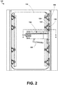
- FIG. 2 illustrates an aircraft door system 120, according to an example.
- the aircraft door system 120 described herein may be utilized in the aircraft 100 described above in relation to Figure 1 .
- aircraft door system 120 includes the aircraft door 110 that is configured to translate from a closed position to an open position.
- the aircraft door 110 is configured to be coupled to the fuselage 106.
- the aircraft door 110 may be a pressurizable passenger door, such as a plug-type aircraft door.
- the aircraft door system 120 further includes a plurality of door pressure stops 122 positioned along a length of the aircraft door 110.
- the plurality of door pressure stops 122 contact a corresponding plurality of fuselage pressure stops 124 when the aircraft door 110 is in the closed position.
- the plurality of door pressure stops 122 transfer pressure loads reacted by the aircraft door 110 to the corresponding plurality of fuselage pressure stops 124.
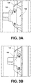
- Figure 3A illustrates a detailed view of a door pressure stop 122 and corresponding fuselage pressure stop 124 of the aircraft door system 120 of Figure 2 when the aircraft door 110 is in a closed position, according to an example.
- the fuselage pressure stop 124 includes an opening 126 sized to allow the door pressure stop 122 to move past the fuselage pressure stop 124 in order for the aircraft door 110 to transition to the open position, as discussed in additional detail below.
- the aircraft door system 120 further includes a handle 128 coupled to the aircraft door 110.
- a rotation of the handle 128 causes a first translation of the aircraft door 110 in an inward direction (e.g., in a direction towards the cabin 112 of the aircraft 100) and a forward direction (e.g., in a direction towards the nose 102 of the aircraft 100) such that the plurality of door pressure stops 122 no longer contact the corresponding plurality of fuselage pressure stops 124.
- FIG. 3B illustrates a detailed view of a door pressure stop 122 and corresponding fuselage pressure stop 124 of the aircraft door system 120 of Figure 2 when the aircraft door 110 is in the process of translating to an open position in response to the rotation of the handle 128, according to an example.
- the door pressure stop 122 moves so that it is aligned with the opening 126 in the fuselage pressure stop 124, so that a subsequent movement of the aircraft door 110 in an outward direction (e.g., in a direction away from the cabin 112 of the aircraft 100) enables the door pressure stop 122 to move past the fuselage pressure stop 124 in order for the aircraft door 110 to fully transition to the open position.
- the aircraft door system 120 further includes a hinge system 130 coupled to the aircraft door 110.
- the hinge system 130 is located on the right of the aircraft door 110 which corresponds to the forward side of the aircraft door 110. Hence, the aircraft door 110 opens forwardly.
- the hinge system 130 is located on the left of the aircraft door 110 such that the aircraft door 110 opens rearwardly.
- the following description describes forwardly opening aircraft door 110. It will be clear to those skilled in the art how the hinge system 130 and the rest of the aircraft door 110 could be adapted to open rearwardly.
- an outward force (e.g., in a direction away from the cabin 112 of the aircraft 100) applied to the aircraft door 110 causes a second translation of the aircraft door 110 in an outward direction (e.g., in a direction away from the cabin 112 of the aircraft 100) and a forward direction (in a direction towards the nose 102 of the aircraft 100).
- the hinge system 130 causes the aircraft door 110 to translate such that the aircraft door 110 remains parallel to the fuselage 106 throughout an entirety of the second translation until the aircraft door 110 reaches the open position.
- the hinge system 130 may be positioned entirely within an interior of the aircraft door 110, and the handle 128 extends to an exterior of the aircraft door 110 to receive input from a user.
- a height of the aircraft door 110 relative to the fuselage 106 does not change when translating the aircraft door 110 from the closed position to the open position.
- the double translation of the aircraft door 110 described above enables the plurality of door pressure stops 122 of the aircraft door 110 to move past the corresponding plurality of fuselage pressure stops 124 without the need for a heavy counterbalance system as the height of the aircraft door 110 remains constant throughout its motion.
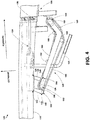
- Figure 4 is a detailed top cross-sectional view along A-A of the aircraft door system 120 of Figure 2 , according to an example.
- the handle 128 is coupled to a linkage system 134, which is in coupled to a roller crank 136.
- the rotation of the handle 128 is translated to the linkage system 134, which in turn causes the roller crank 136 to initiate the first translation of the aircraft door 110 in an inward direction (e.g., in a direction towards the cabin 112 of the aircraft 100) and a forward direction (e.g., in a direction towards the nose 102 of the aircraft 100) such that the plurality of door pressure stops 122 no longer contact the corresponding plurality of fuselage pressure stops 124.
- the hinge system 130 may include an aft idler 138 having a first end 140 and a second end 142, and the second end 142 of the aft idler 138 is coupled to the aircraft door 110.
- the hinge system 130 may further include a forward idler 144 having a first end 148 and a second end 146, and the second end 146 of the forward idler 144 is coupled to the aircraft door 110.
- the hinge system 130 may further include a programming yoke 150 having a first end 152 and a second end 154.
- the first end 152 of the programming yoke 150 is coupled to the first end 140 of the aft idler 138, and the second end 154 of the programming yoke 150 is coupled to the first end 148 of the forward idler 144.
- the hinge system 130 may further include a first pulley 156 coupled to the programming yoke 150 between the first end 152 of the programming yoke 150 and the second end 154 of the programming yoke 150.
- the hinge system 130 may further include a second pulley 158 configured to be coupled to the fuselage 106.
- the hinge system 130 may further include a gooseneck hinge 160 having a first end 162 and a second end 164.
- the first end 162 of the gooseneck hinge 160 is coupled to the first pulley 156, and the second end 164 of the gooseneck hinge 160 is coupled to the second pulley 158.
- the second end 164 of the gooseneck hinge 160 is coupled to the fuselage 106.
- the hinge system 130 may further include a drive element 166 positioned around the first pulley 156 and the second pulley 158.
- the drive element 166 may comprise one of a belt, a chain, or a chord.
- Each of the aft idler 138, forward idler 144, programming yoke 150, first pulley 156, second pulley 158, gooseneck hinge 160, and drive element 166 may be positioned within an interior of the aircraft door 110, such that only a portion of handle 128 extends to an exterior of the aircraft door 110 to receive the rotational input from a user.
- the gooseneck hinge 160 is configured to rotate 140 degrees or approximately 140 degrees as the aircraft door 110 translates from the closed position to the open position.
- the gooseneck hinge 160 further includes a plurality of pulleys 168 configured to contact the drive element 166 between the first end 162 of the gooseneck hinge 160 and the second end 164 of the gooseneck hinge 160.
- the plurality of pulleys 168 in combination with the first pulley 156 and the second pulley 158 enable the drive element 166 to move freely around the gooseneck hinge 160 to enable the programming yoke 150 to rotate at a 1:1 rate with respect to the fuselage 106 thus programming the aircraft door 110 to translate to the open position while remaining parallel to the fuselage 106.
- the second pulley 158 is grounded to the fuselage 106 which imparts the 1:1 spin into the programming yoke 150.
- the aircraft door 110 moves parallel to the programming yoke 150, which is spinning about the first end 162 of the gooseneck hinge 160.
- a user can apply an outward force to the aircraft door 110 via the handle 128.
- the aircraft door 110 moves outward, the aircraft door 110 rotates around its couple with the fuselage 106.
- the gooseneck hinge 160 is separately connected to the fuselage 106, for example via single pin joints.
- the second pulley 158 is connected to the gooseneck hinge 160 and grounded to the fuselage 106.
- the four-bar linkage formed by the aircraft door 110, the aft idler 138, the forward idler 144, and the programming yoke 150 in combination with the first pulley 156, the second pulley 158, and the drive element 166 causes the programming yoke 150 to rotate at a 1:1 rate relative to the fuselage 106 to maintain the aircraft door 110 parallel to the fuselage 106 throughout the opening process.
- the 1:1 relationship is between the programming yoke 150 and the fuselage 106, which grounds the second pulley 158.
- the programming yoke 150 spins relative to the gooseneck hinge 160.
- the drive element 166 takes any angular change made at the gooseneck hinge 160 and fuselage 106 coupling and transmits it to the programming yoke 150. Therefore, as the aircraft door 110 opens, the programming yoke 150 moves parallel to the fuselage 106.
- the aircraft door 110 remains parallel as well by way of the four-bar linkage that connects the aircraft door 110 to the programming yoke 150.
- Figures 5A-5C illustrate the aircraft door system 120 of Figure 2 in various stages of transition from the closed position to the open position.
- Figure 5A illustrates the aircraft door system 120 of Figure 2 with the aircraft door in the closed positioned.
- Figure 5B illustrates the aircraft door system 120 of Figure 2 with the aircraft door unlatched but not yet open.
- the rotation of the handle 128 initiates the first translation of the aircraft door 110 in an inward direction (e.g., in a direction towards the cabin 112 of the aircraft 100) and a forward direction (e.g., in a direction towards the nose 102 of the aircraft 100) such that the plurality of door pressure stops 122 no longer contact the corresponding plurality of fuselage pressure stops 124.
- Figure 5C illustrates the aircraft door system 120 of Figure 2 transitioning to an open position.
- an outward force e.g., in a direction away from the cabin 112 of the aircraft 100
- the application of an outward force on the aircraft door 110 after the handle 128 has been rotated initiates the second translation of the aircraft door 110 in an outward direction (e.g., in a direction away from the cabin 112 of the aircraft 100) and a forward direction (in a direction towards the nose 102 of the aircraft 100).
- the hinge system 130 of the aircraft door system 120 causes the aircraft door 110 to translate such that the aircraft door 110 remains parallel to the fuselage 106 throughout an entirety of the second translation until the aircraft door 110 reaches the open position.
- Figure 6 is a block diagram of an example of a method for establishing an aircraft door system 120 of an aircraft 100.
- Method 200 shown in Figure 6 presents an example of a method that could be used with any of the examples of the aircraft 100 and the aircraft door system 120 discussed above in relation to Figures 1-5C , as examples.
- Method 200 includes one or more operations, functions, or actions as illustrated by one or more of blocks 202-210. Although the blocks are illustrated in a sequential order, these blocks may also be performed in parallel, and/or in a different order than those described herein. Also, the various blocks may be combined into fewer blocks, divided into additional blocks, and/or removed based upon the desired implementation.
- the method 200 includes coupling an aircraft door 110 to a fuselage 106 of the aircraft 100.
- the fuselage 106 includes a fuselage cutout 114, and the aircraft door 110 configured to translate from a closed position in which the aircraft door 110 covers the fuselage cutout 114 to an open position in which at least a portion of the aircraft door 110 is forward of the fuselage cutout 114.
- the method 200 includes positioning a plurality of door pressure stops 122 along a length of the aircraft door 110.
- the method 200 includes positioning a plurality of fuselage pressure stops 124 to contact the plurality of door pressure stops 122 when the aircraft door is in the closed position. As discussed above, the interaction of the plurality of door pressure stops 122 and the plurality of fuselage pressure stops 124 transfer pressure loads from the aircraft door 110 to the fuselage 106 when the aircraft 100 is pressurized.
- the method 200 includes coupling a handle 128 to the aircraft door 110.
- a rotation of the handle 128 causes a first translation of the aircraft door 110 in an inward direction and a forward direction such that the plurality of door pressure stops 122 no longer contact the plurality of fuselage pressure stops 124.
- the method 200 includes coupling a hinge system 130 to the aircraft door 110.
- a hinge system 130 causes the aircraft door 110 to translate such that the aircraft door 110 remains parallel to the fuselage 106 throughout an entirety of the second translation until the aircraft door 110 reaches the open position.
Landscapes
- Engineering & Computer Science (AREA)
- Mechanical Engineering (AREA)
- Aviation & Aerospace Engineering (AREA)
- Power-Operated Mechanisms For Wings (AREA)
Abstract
Description
- The present disclosure relates generally to an aircraft door system, and more particularly, to an initially inward opening pressurizable passenger entry aircraft door system with a double translating hinge motion.
- Many aircrafts provide pressurizable doors that provide an entry and/or exit (or emergency egress) for passengers into and out of the aircraft. When such a pressurizable aircraft door is closed, latched, and locked, a plurality of door pressure stops must transfer pressure loads reacted by the aircraft door to adjacent aircraft fuselage structure around the aircraft door after the plane has initiated takeoff and the environmental cabin system (ECS) has initiated pressurization. However, the aircraft door must be able to move past these door pressure stops in order to open.
- The most common way for an aircraft door to move past these door pressure stops is to lift the door high enough so as to provide adequate clearance between the door pressure stops and the corresponding fuselage pressure stops. To accomplish such a lift, which is traditionally mechanically actuated by the main door handle, such doors are equipped with robust counterbalance systems to counteract the weight of the door and emergency escape equipment that is mounted to the door. Such a counterbalance system adds weight and complexity to the aircraft door system. Therefore, an aircraft door system that enables the aircraft door to move past the fuselage pressure stops without lifting the door may be desirable.
- There is described herein an aircraft door system that includes (a) an aircraft door configured to translate from a closed position to an open position, wherein the aircraft door is configured to be coupled to an aircraft fuselage, (b) a plurality of door pressure stops positioned along a length of the aircraft door, wherein the plurality of door pressure stops contact a corresponding plurality of fuselage pressure stops when the aircraft door is in the closed position, (c) a handle coupled to the aircraft door, wherein a rotation of the handle causes a first translation of the aircraft door in an inward direction and a forward (or rearward) direction such that the plurality of door pressure stops no longer contact the corresponding plurality of fuselage pressure stops, and (d) a hinge system coupled to the aircraft door, wherein an outward force applied to the aircraft door causes a second translation of the aircraft door in an outward direction and a forward (or rearward) direction, and wherein the hinge system causes the aircraft door to translate such that the aircraft door remains parallel to the aircraft fuselage throughout an entirety of the second translation until the aircraft door reaches the open position.
- There is described herein an aircraft that includes (a) a fuselage including a fuselage cutout, (b) an aircraft door coupled to the fuselage, wherein the aircraft door is configured to translate from a closed position in which the aircraft door covers the fuselage cutout to an open position in which at least a portion of the aircraft door is forward (or aft) of the fuselage cutout, (c) a plurality of door pressure stops positioned along a length of the aircraft door, (d) a plurality of fuselage pressure stops configured to contact the plurality of door pressure stops when the aircraft door is in the closed position, (e) a handle coupled to the aircraft door, wherein a rotation of the handle causes a first translation of the aircraft door in an inward direction and a forward (or rearward) direction such that the plurality of door pressure stops no longer contact the plurality of fuselage pressure stops, (f) a hinge system coupled to the aircraft door, wherein an outward force applied to the aircraft door causes a second translation of the aircraft door in an outward direction and a forward (or rearward) direction, and wherein the hinge system causes the aircraft door to translate such that the aircraft door remains parallel to the fuselage throughout an entirety of the second translation until the aircraft door reaches the open position.
- There is described herein a method for establishing an aircraft door system of an aircraft described. The method includes (a) coupling an aircraft door to a fuselage of the aircraft, wherein the fuselage includes a fuselage cutout, and wherein the aircraft door is configured to translate from a closed position in which the aircraft door covers the fuselage cutout to an open position in which at least a portion of the aircraft door is forward (or aft) of the fuselage cutout, (b) positioning a plurality of door pressure stops positioned along a length of the aircraft door, (c) positioning a plurality of fuselage pressure stops to contact the plurality of door pressure stops when the aircraft door is in the closed position, (d) coupling a handle to the aircraft door, wherein a rotation of the handle causes a first translation of the aircraft door in an inward direction and a forward (or rearward) direction such that the plurality of door pressure stops no longer contact the plurality of fuselage pressure stops, and (e) coupling a hinge system to the aircraft door, wherein an outward force applied to the aircraft door causes a second translation of the aircraft door in an outward direction and a forward (or rearward) direction, and wherein the hinge system causes the aircraft door to translate such that the aircraft door remains parallel to the fuselage throughout an entirety of the second translation until the aircraft door reaches the open position.
- The features, functions, and advantages that have been discussed can be achieved independently in various examples or may be combined in yet other examples further details of which can be seen with reference to the following description and figures.
- The novel features believed characteristic of the illustrative examples are set forth in the appended claims. The illustrative examples, however, as well as a preferred mode of use, further objectives and descriptions thereof, will best be understood by reference to the following detailed description of an illustrative examples of the present disclosure when read in conjunction with the accompanying figures.
-
Figure 1 is a perspective view of an aircraft. -
Figure 2 a side view (looking outboard) of an aircraft door system. -
Figure 3A illustrates a detailed view of a door pressure stop and corresponding fuselage pressure stop of the aircraft door system ofFigure 2 when the aircraft door is in a closed position. -
Figure 3B illustrates a detailed view of a door pressure stop and corresponding fuselage pressure stop of the aircraft door system ofFigure 2 when the aircraft door is translating to an open position. -
Figure 4 is a detailed top cross-sectional view along A-A of the aircraft door system ofFigure 2 . -
Figure 5A illustrates the aircraft door system ofFigure 2 with the aircraft door in a closed positioned. -
Figure 5B illustrates the aircraft door system ofFigure 2 with the aircraft door unlatched but not yet open. -
Figure 5C illustrates the aircraft door system ofFigure 2 with the aircraft door transitioning to an open position. -
Figure 6 is a flowchart of an example method. - Disclosed examples will now be described more fully hereinafter with reference to the accompanying figures, in which some, but not all of the disclosed examples are shown. Indeed, several different examples may be provided and should not be construed as limited to the examples set forth herein. Rather, these examples are provided so that this disclosure will be thorough and complete and will fully convey the scope of the disclosure to those skilled in the art.
- In the following description, numerous specific details are set forth to provide a thorough understanding of the disclosed concepts, which may be practiced without some or all of these particulars. In other instances, details of known devices and/or processes have been omitted to avoid unnecessarily obscuring the disclosure. While some concepts will be described in conjunction with specific examples, it will be understood that these examples are not intended to be limiting.
- In
Figure 6 , the blocks represent operations and/or portions thereof and lines connecting the various blocks do not imply any particular order or dependency of the operations or portions thereof. It will be understood that not all dependencies among the various disclosed operations are necessarily represented.Figure 6 and the accompanying disclosure describing the operations of the method(s) set forth herein should not be interpreted as necessarily determining a sequence in which the operations are to be performed. Rather, although one illustrative order is indicated, it is to be understood that the sequence of the operations may be modified when appropriate. Accordingly, certain operations may be performed in a different order or simultaneously. Additionally, those skilled in the art will appreciate that not all operations described need be performed. - Unless otherwise indicated, the terms "first," "second," etc. are used herein merely as labels, and are not intended to impose ordinal, positional, or hierarchical requirements on the items to which these terms refer. Moreover, reference to, e.g., a "second" item does not require or preclude the existence of, e.g., a "first" or lower-numbered item, and/or, e.g., a "third" or higher-numbered item.
- Reference herein to "one example" means that one or more feature, structure, or characteristic described in connection with the example is included in at least one implementation. The phrase "one example" in various places in the specification may or may not be referring to the same example.
- As used herein, a system, apparatus, device, structure, article, element, component, or hardware "configured to" perform a specified function is indeed capable of performing the specified function without any alteration, rather than merely having potential to perform the specified function after further modification. In other words, the system, apparatus, structure, article, element, component, or hardware "configured to" perform a specified function is specifically selected, created, implemented, utilized, programmed, and/or designed for the purpose of performing the specified function. As used herein, "configured to" denotes existing characteristics of a system, apparatus, structure, article, element, component, or hardware which enable the system, apparatus, structure, article, element, component, or hardware to perform the specified function without further modification. For purposes of this disclosure, a system, apparatus, structure, article, element, component, or hardware described as being "configured to" perform a particular function may additionally or alternatively be described as being "adapted to" and/or as being "operative to" perform that function.
- Unless otherwise specifically noted, elements depicted in the drawings are not necessarily drawn to scale.
- Illustrative, non-exhaustive examples, which may or may not be claimed, of the subject matter according the present disclosure are provided below.
- With reference to the Figures,
Figure 1 is a perspective view of anaircraft 100, according to an example. Theaircraft 100 includes anose 102,wings 104A-104B, afuselage 106, and atail 108, according to an example. Theaircraft 100 includes many areas arranged for storage of items during flight. In some examples, thefuselage 106 includes storage underneath a passenger compartment for storing luggage and other items or supplies. In some examples, the passenger compartment in thefuselage 106 includes overhead bins and under seat areas for storing further items. As further illustrated inFigure 1 , theaircraft 100 includes anaircraft door 110 that provides entry and/or exit to and from thecabin 112 of theaircraft 100. As shown inFigure 1 , thefuselage 106 includes afuselage cutout 114, and theaircraft door 110 is configured to translate from a closed position in which theaircraft door 110 covers thefuselage cutout 114 in thefuselage 106 to an open position (shown inFigure 1 ) in which at least a portion of theaircraft door 110 is forward of thefuselage cutout 114 to thereby enable entry and/or exit to and from thecabin 112 of theaircraft 100. In some examples, an entirety of theaircraft door 110 is forward of thefuselage cutout 114 when theaircraft door 110 is in the open position. Theaircraft door 110 need not open forwardly, but could open rearwardly. For example, in some examples, theaircraft door 110 may be configured to translate from a closed position in which theaircraft door 110 covers thefuselage cutout 114 in thefuselage 106 to an open position (shown inFigure 1 ) in which at least a portion of theaircraft door 110 is aft of thefuselage cutout 114. In some examples, an entirety of theaircraft door 110 is aft of thefuselage cutout 114 when theaircraft door 110 is in the open position. As shown inFigure 1 , theaircraft 100 may further include asecond aircraft door 116 and athird aircraft door 118 that may be similarly configured as theaircraft door 110. Additional numbers of aircraft doors are possible as well. Allaircraft doors 110 may open forwardly or rearwardly or there may be a combination of both. -
Figure 2 illustrates anaircraft door system 120, according to an example. Theaircraft door system 120 described herein may be utilized in theaircraft 100 described above in relation toFigure 1 . As shown inFigure 2 ,aircraft door system 120 includes theaircraft door 110 that is configured to translate from a closed position to an open position. Theaircraft door 110 is configured to be coupled to thefuselage 106. - In some examples, the
aircraft door 110 may be a pressurizable passenger door, such as a plug-type aircraft door. As such, and as shown inFigure 2 , theaircraft door system 120 further includes a plurality of door pressure stops 122 positioned along a length of theaircraft door 110. The plurality of door pressure stops 122 contact a corresponding plurality of fuselage pressure stops 124 when theaircraft door 110 is in the closed position. When theaircraft door 110 is fully closed, the plurality of door pressure stops 122 transfer pressure loads reacted by theaircraft door 110 to the corresponding plurality of fuselage pressure stops 124.Figure 3A illustrates a detailed view of a door pressure stop 122 and corresponding fuselage pressure stop 124 of theaircraft door system 120 ofFigure 2 when theaircraft door 110 is in a closed position, according to an example. As shown inFigure 3A , the fuselage pressure stop 124 includes anopening 126 sized to allow the door pressure stop 122 to move past the fuselage pressure stop 124 in order for theaircraft door 110 to transition to the open position, as discussed in additional detail below. - As shown in
Figure 2 , theaircraft door system 120 further includes ahandle 128 coupled to theaircraft door 110. A rotation of thehandle 128 causes a first translation of theaircraft door 110 in an inward direction (e.g., in a direction towards thecabin 112 of the aircraft 100) and a forward direction (e.g., in a direction towards thenose 102 of the aircraft 100) such that the plurality of door pressure stops 122 no longer contact the corresponding plurality of fuselage pressure stops 124. For a rearwardlyopening aircraft door 110, rotation of thehandle 128 causes a first translation of theaircraft door 110 in the inward direction and a rearward direction (e.g., in a direction towards thetail 108 of the aircraft 100) such that the plurality of door pressure stops 122 no longer contact the corresponding plurality of fuselage pressure stops 124.Figure 3B illustrates a detailed view of a door pressure stop 122 and corresponding fuselage pressure stop 124 of theaircraft door system 120 ofFigure 2 when theaircraft door 110 is in the process of translating to an open position in response to the rotation of thehandle 128, according to an example. In particular, as shown inFigure 3B , when thehandle 128 is rotated, the door pressure stop 122 moves so that it is aligned with theopening 126 in the fuselage pressure stop 124, so that a subsequent movement of theaircraft door 110 in an outward direction (e.g., in a direction away from thecabin 112 of the aircraft 100) enables the door pressure stop 122 to move past the fuselage pressure stop 124 in order for theaircraft door 110 to fully transition to the open position. - As shown in
Figure 2 , theaircraft door system 120 further includes ahinge system 130 coupled to theaircraft door 110. InFigure 2 , thehinge system 130 is located on the right of theaircraft door 110 which corresponds to the forward side of theaircraft door 110. Hence, theaircraft door 110 opens forwardly. In some alternative examples, thehinge system 130 is located on the left of theaircraft door 110 such that theaircraft door 110 opens rearwardly. For the sake of brevity, the following description describes forwardly openingaircraft door 110. It will be clear to those skilled in the art how thehinge system 130 and the rest of theaircraft door 110 could be adapted to open rearwardly. After the first translation occurs and the door pressure stops 122 are clear of the fuselage pressure stops 124, an outward force (e.g., in a direction away from thecabin 112 of the aircraft 100) applied to theaircraft door 110 causes a second translation of theaircraft door 110 in an outward direction (e.g., in a direction away from thecabin 112 of the aircraft 100) and a forward direction (in a direction towards thenose 102 of the aircraft 100). In use, thehinge system 130 causes theaircraft door 110 to translate such that theaircraft door 110 remains parallel to thefuselage 106 throughout an entirety of the second translation until theaircraft door 110 reaches the open position. Thehinge system 130 may be positioned entirely within an interior of theaircraft door 110, and thehandle 128 extends to an exterior of theaircraft door 110 to receive input from a user. - A height of the
aircraft door 110 relative to thefuselage 106 does not change when translating theaircraft door 110 from the closed position to the open position. As such, the double translation of theaircraft door 110 described above enables the plurality of door pressure stops 122 of theaircraft door 110 to move past the corresponding plurality of fuselage pressure stops 124 without the need for a heavy counterbalance system as the height of theaircraft door 110 remains constant throughout its motion. -
Figure 4 is a detailed top cross-sectional view along A-A of theaircraft door system 120 ofFigure 2 , according to an example. As shown inFigure 4 , thehandle 128 is coupled to alinkage system 134, which is in coupled to a roller crank 136. When thehandle 128 is rotated, the rotation of thehandle 128 is translated to thelinkage system 134, which in turn causes the roller crank 136 to initiate the first translation of theaircraft door 110 in an inward direction (e.g., in a direction towards thecabin 112 of the aircraft 100) and a forward direction (e.g., in a direction towards thenose 102 of the aircraft 100) such that the plurality of door pressure stops 122 no longer contact the corresponding plurality of fuselage pressure stops 124. - As further shown in
Figure 4 , thehinge system 130 may include anaft idler 138 having afirst end 140 and asecond end 142, and thesecond end 142 of theaft idler 138 is coupled to theaircraft door 110. Thehinge system 130 may further include aforward idler 144 having afirst end 148 and asecond end 146, and thesecond end 146 of theforward idler 144 is coupled to theaircraft door 110. Thehinge system 130 may further include aprogramming yoke 150 having afirst end 152 and asecond end 154. Thefirst end 152 of theprogramming yoke 150 is coupled to thefirst end 140 of theaft idler 138, and thesecond end 154 of theprogramming yoke 150 is coupled to thefirst end 148 of theforward idler 144. Thehinge system 130 may further include afirst pulley 156 coupled to theprogramming yoke 150 between thefirst end 152 of theprogramming yoke 150 and thesecond end 154 of theprogramming yoke 150. Thehinge system 130 may further include asecond pulley 158 configured to be coupled to thefuselage 106. Thehinge system 130 may further include agooseneck hinge 160 having afirst end 162 and asecond end 164. Thefirst end 162 of thegooseneck hinge 160 is coupled to thefirst pulley 156, and thesecond end 164 of thegooseneck hinge 160 is coupled to thesecond pulley 158. In addition, thesecond end 164 of thegooseneck hinge 160 is coupled to thefuselage 106. Thehinge system 130 may further include adrive element 166 positioned around thefirst pulley 156 and thesecond pulley 158. Thedrive element 166 may comprise one of a belt, a chain, or a chord. Each of theaft idler 138, forward idler 144,programming yoke 150,first pulley 156,second pulley 158,gooseneck hinge 160, and driveelement 166 may be positioned within an interior of theaircraft door 110, such that only a portion ofhandle 128 extends to an exterior of theaircraft door 110 to receive the rotational input from a user. - In some examples, the
gooseneck hinge 160 is configured to rotate 140 degrees or approximately 140 degrees as theaircraft door 110 translates from the closed position to the open position. In some examples, thegooseneck hinge 160 further includes a plurality ofpulleys 168 configured to contact thedrive element 166 between thefirst end 162 of thegooseneck hinge 160 and thesecond end 164 of thegooseneck hinge 160. The plurality ofpulleys 168 in combination with thefirst pulley 156 and thesecond pulley 158 enable thedrive element 166 to move freely around thegooseneck hinge 160 to enable theprogramming yoke 150 to rotate at a 1:1 rate with respect to thefuselage 106 thus programming theaircraft door 110 to translate to the open position while remaining parallel to thefuselage 106. In particular, thesecond pulley 158 is grounded to thefuselage 106 which imparts the 1:1 spin into theprogramming yoke 150. Theaircraft door 110 moves parallel to theprogramming yoke 150, which is spinning about thefirst end 162 of thegooseneck hinge 160. - In use, after the
handle 128 is rotated to disengage the plurality of door pressure stops 122 from the corresponding plurality of fuselage pressure stops 124, a user can apply an outward force to theaircraft door 110 via thehandle 128. As theaircraft door 110 moves outward, theaircraft door 110 rotates around its couple with thefuselage 106. As mentioned above, thegooseneck hinge 160 is separately connected to thefuselage 106, for example via single pin joints. Thesecond pulley 158 is connected to thegooseneck hinge 160 and grounded to thefuselage 106. The four-bar linkage formed by theaircraft door 110, theaft idler 138, theforward idler 144, and theprogramming yoke 150 in combination with thefirst pulley 156, thesecond pulley 158, and thedrive element 166 causes theprogramming yoke 150 to rotate at a 1:1 rate relative to thefuselage 106 to maintain theaircraft door 110 parallel to thefuselage 106 throughout the opening process. - As such, the 1:1 relationship is between the
programming yoke 150 and thefuselage 106, which grounds thesecond pulley 158. Theprogramming yoke 150 spins relative to thegooseneck hinge 160. Thedrive element 166 takes any angular change made at thegooseneck hinge 160 andfuselage 106 coupling and transmits it to theprogramming yoke 150. Therefore, as theaircraft door 110 opens, theprogramming yoke 150 moves parallel to thefuselage 106. Theaircraft door 110 remains parallel as well by way of the four-bar linkage that connects theaircraft door 110 to theprogramming yoke 150. -
Figures 5A-5C illustrate theaircraft door system 120 ofFigure 2 in various stages of transition from the closed position to the open position. In particular,Figure 5A illustrates theaircraft door system 120 ofFigure 2 with the aircraft door in the closed positioned. -
Figure 5B illustrates theaircraft door system 120 ofFigure 2 with the aircraft door unlatched but not yet open. Such an arrangement occurs when the user rotates thehandle 128 of theaircraft door 110. As discussed above, the rotation of thehandle 128 initiates the first translation of theaircraft door 110 in an inward direction (e.g., in a direction towards thecabin 112 of the aircraft 100) and a forward direction (e.g., in a direction towards thenose 102 of the aircraft 100) such that the plurality of door pressure stops 122 no longer contact the corresponding plurality of fuselage pressure stops 124. -
Figure 5C illustrates theaircraft door system 120 ofFigure 2 transitioning to an open position. Such an arrangement occurs when the user applies an outward force (e.g., in a direction away from thecabin 112 of the aircraft 100) to theaircraft door 110. As discussed above, the application of an outward force on theaircraft door 110 after thehandle 128 has been rotated initiates the second translation of theaircraft door 110 in an outward direction (e.g., in a direction away from thecabin 112 of the aircraft 100) and a forward direction (in a direction towards thenose 102 of the aircraft 100). Thehinge system 130 of theaircraft door system 120 causes theaircraft door 110 to translate such that theaircraft door 110 remains parallel to thefuselage 106 throughout an entirety of the second translation until theaircraft door 110 reaches the open position. -
Figure 6 is a block diagram of an example of a method for establishing anaircraft door system 120 of anaircraft 100.Method 200 shown inFigure 6 presents an example of a method that could be used with any of the examples of theaircraft 100 and theaircraft door system 120 discussed above in relation toFigures 1-5C , as examples.Method 200 includes one or more operations, functions, or actions as illustrated by one or more of blocks 202-210. Although the blocks are illustrated in a sequential order, these blocks may also be performed in parallel, and/or in a different order than those described herein. Also, the various blocks may be combined into fewer blocks, divided into additional blocks, and/or removed based upon the desired implementation. - Initially, at
block 202, themethod 200 includes coupling anaircraft door 110 to afuselage 106 of theaircraft 100. Thefuselage 106 includes afuselage cutout 114, and theaircraft door 110 configured to translate from a closed position in which theaircraft door 110 covers thefuselage cutout 114 to an open position in which at least a portion of theaircraft door 110 is forward of thefuselage cutout 114. - At
block 204, themethod 200 includes positioning a plurality of door pressure stops 122 along a length of theaircraft door 110. Atblock 206, themethod 200 includes positioning a plurality of fuselage pressure stops 124 to contact the plurality of door pressure stops 122 when the aircraft door is in the closed position. As discussed above, the interaction of the plurality of door pressure stops 122 and the plurality of fuselage pressure stops 124 transfer pressure loads from theaircraft door 110 to thefuselage 106 when theaircraft 100 is pressurized. - At
block 208, themethod 200 includes coupling ahandle 128 to theaircraft door 110. As discussed above, a rotation of thehandle 128 causes a first translation of theaircraft door 110 in an inward direction and a forward direction such that the plurality of door pressure stops 122 no longer contact the plurality of fuselage pressure stops 124. - At
block 210, themethod 200 includes coupling ahinge system 130 to theaircraft door 110. As discussed above, an outward force applied to theaircraft door 110 causes a second translation of theaircraft door 110 in an outward direction and a forward direction. Further, thehinge system 130 causes theaircraft door 110 to translate such that theaircraft door 110 remains parallel to thefuselage 106 throughout an entirety of the second translation until theaircraft door 110 reaches the open position. - It should be understood that arrangements described herein are for purposes of example only. As such, those skilled in the art will appreciate that other arrangements and other elements (e.g. machines, interfaces, functions, orders, and groupings of functions, etc.) can be used instead, and some elements may be omitted altogether according to the desired results. Further, many of the elements that are described are functional entities that may be implemented as discrete or distributed components or in conjunction with other components, in any suitable combination and location, or other structural elements described as independent structures may be combined.
- Further, the disclosure comprises examples according to the following clauses:
- Clause 1. An aircraft door system (120) comprising: an aircraft door (110) configured to translate from a closed position to an open position, wherein the aircraft door (110) is configured to be coupled to an aircraft fuselage (106); a plurality of door pressure stops (122) positioned along a length of the aircraft door (110), wherein the plurality of door pressure stops (122) contact a corresponding plurality of fuselage pressure stops (124) when the aircraft door (110) in the closed position; a handle (128) coupled to the aircraft door (110), wherein a rotation of the handle (128) causes a first translation of the aircraft door (110) in an inward direction and a forward direction such that the plurality of door pressure stops (122) no longer contact the corresponding plurality of fuselage pressure stops (124); and a hinge system (130) coupled to the aircraft door (110), wherein an outward force applied to the aircraft door (110) causes a second translation of the aircraft door (110) in an outward direction and a forward direction, and wherein the hinge system (130) causes the aircraft door (110) to translate such that the aircraft door (110) remains parallel to the aircraft fuselage (106) throughout an entirety of the second translation until the aircraft door (110) reaches the open position.
- Clause 2. The aircraft door system (120) of Clause 1, wherein the hinge system (130) comprises: an aft idler (138) having a first end (140) and a second end (142), wherein the second end (142) of the aft idler (138) is coupled to the aircraft door (110); a forward idler (144) having a first end (146) and a second end (148), wherein the second end (148) the forward idler (144) is coupled to the aircraft door (110); a programming yoke (150) having a first end (152) and a second end (154), wherein the first end (152) of the programming yoke (150) is coupled to the first end (152) of the aft idler (138), and wherein the second end (154) of the programming yoke (150) is coupled to the first end (146) of the forward idler (144); a first pulley (156) coupled to the programming yoke (150) between the first end (152) of the programming yoke (150) and the second end (154) of the programming yoke (150); a gooseneck hinge (160) having a first end (162) and a second end (164), wherein the first end (162) of the gooseneck hinge (160) is coupled to the first pulley (156); a second pulley (158) configured to be coupled to the aircraft fuselage (106), wherein the second end (164) of the gooseneck hinge (160) is coupled to the second pulley (158); and a drive element (166) positioned around the first pulley (156) and the second pulley (158); and, optionally, wherein: the second pulley (158) is configured to be grounded to the fuselage (106); and the first pulley (156) and the second pulley (158) enable the drive element (166) to move freely around the gooseneck hinge (160) to enable the programming yoke (150) to rotate at a 1:1 rate with respect to the fuselage (106) thus programming the aircraft door (110) to translate to the open position while remaining parallel to the fuselage (106).
- Clause 3. The aircraft door system (120) of Clause 2, wherein the drive element (166) comprises one of a belt, a chain, or a chord.
- Clause 4. The aircraft door system (120) of Clause 2 or 3, wherein the gooseneck hinge (160) is configured to rotate 140 degrees or approximately 140 degrees as the aircraft door (110) translates from the closed position to the open position.
- Clause 5. The aircraft door system (120) of any one of Clauses 2-4, wherein the gooseneck hinge (160) further includes a plurality of pulleys (168) configured to contact the drive element (166) between the first end (162) of the gooseneck hinge (160) and the second end (164) of the gooseneck hinge (160).
- Clause 6. The aircraft door system (120) of any one of Clauses 2-5, wherein each of the aft idler (138), forward idler (144), programming yoke (150), first pulley (156), second pulley (158), gooseneck hinge (160), and drive element (166) are positioned within an interior of the aircraft door (110), and wherein the handle (128) extends to an exterior of the aircraft door (110).
- Clause 7. The aircraft door system (120) of any one of Clauses 1-6, wherein a height of the aircraft (110) relative to the aircraft fuselage (106) does not change when translating the aircraft door (110) from the closed position to the open position.
- Clause 8. The aircraft door system (120) of any one of Clauses 1-7, wherein the aircraft door (110) covers a fuselage cutout (114) in the aircraft fuselage (106) in the closed position, and wherein at least a portion of the aircraft door (110) is forward of the fuselage cutout (114) in the open position.
- Clause 9. An aircraft (100) comprising: a fuselage (106) including a fuselage cutout (114); an aircraft door (110) coupled to the fuselage (106), wherein the aircraft door (110) is configured to translate from a closed position in which the aircraft door (110) covers the fuselage cutout (114) to an open position in which at least a portion of the aircraft door (110) is forward of the fuselage cutout (114); a plurality of door pressure stops (122) positioned along a length of the aircraft door (110); a plurality of fuselage pressure stops (124) configured to contact the plurality of door pressure stops (122) when the aircraft door (110) is in the closed position; a handle (128) coupled to the aircraft door (110), wherein a rotation of the handle (128) causes a first translation of the aircraft door (110) in an inward direction and a forward direction such that the plurality of door pressure stops (122) no longer contact the plurality of fuselage pressure stops (124); and a hinge system (130) coupled to the aircraft door (110), wherein an outward force applied to the aircraft door (110) causes a second translation of the aircraft door (110) in an outward direction and a forward direction, and wherein the hinge system (130) causes the aircraft door (110) to translate such that the aircraft door (110) remains parallel to the fuselage (106) throughout an entirety of the second translation until the aircraft door (110) reaches the open position.
- Clause 10. The aircraft (100) of Clause 9, wherein the hinge system (130) comprises: an aft idler (138) having a first end (140) and a second end (142), wherein the second end (142) of the aft idler (138) is coupled to the aircraft door (110); a forward idler (144) having a first end (146) and a second end (148), wherein the second end (148) the forward idler (144) is coupled to the aircraft door (110); a programming yoke (150) having a first end (152) and a second end (154), wherein the first end (152) of the programming yoke (150) is coupled to the first end (152) of the aft idler (138), and wherein the second end (154) of the programming yoke (150) is coupled to the first end (146) of the forward idler (144); a first pulley (156) coupled to the programming yoke (150) between the first end (152) of the programming yoke (150) and the second end (154) of the programming yoke (150); a gooseneck hinge (160) having a first end (162) and a second end (164), wherein the first end (162) of the gooseneck hinge (160) is coupled to the first pulley (156); a second pulley (158) configured to be coupled to the fuselage (106), wherein the second end (164) of the gooseneck hinge (160) is coupled to the second pulley (158); and a drive element (166) positioned around the first pulley (156) and the second pulley (158); and, optionally, wherein: the second pulley (158) is grounded to the fuselage (106); and the first pulley (156) and the second pulley (158) enable the drive element (166) to move freely around the gooseneck hinge (160) to enable the programming yoke (150) to rotate at a 1:1 rate with respect to the fuselage (106) thus programming the aircraft door (110) to translate to the open position while remaining parallel to the fuselage (106).
- Clause 11. The aircraft (100) of Clause 10, wherein the gooseneck hinge (160) is configured to rotate 140 degrees or approximately 140 degrees as the aircraft door (110) translates from the closed position to the open position.
- Clause 12. The aircraft of Clause 10 or 11, wherein the gooseneck hinge (160) further includes a plurality of pulleys (168) configured to contact the drive element (166) between the first end (162) of the gooseneck hinge (160) and the second end (164) of the gooseneck hinge (160).
- Clause 13. The aircraft of any one of Clauses 9-12, wherein a height of the aircraft door (110) relative to the fuselage (106) does not change when translating the aircraft door (110) from the closed position to the open position.
- Clause 14. The aircraft of any one of Clauses 9-13, wherein at least a portion of the aircraft door (110) is forward of the fuselage cutout (114) when the aircraft door (110) is in the open position.
- Clause 15. A method (200) for establishing an aircraft door system (120) of an aircraft (100), the method (200) comprising: coupling (202) an aircraft door (110) to a fuselage (106) of the aircraft (100), wherein the fuselage (106) includes a fuselage cutout (114), and wherein the aircraft door (110) is configured to translate from a closed position in which the aircraft door (110) covers the fuselage cutout (114) to an open position in which at least a portion of the aircraft door (110) is forward of the fuselage cutout (114); positioning (204) a plurality of door pressure stops (122) along a length of the aircraft door (110); positioning (206) a plurality of fuselage pressure stops (124) to contact the plurality of door pressure stops (122) when the aircraft door (110) is in the closed position; coupling (208) a handle (128) to the aircraft door (110), wherein a rotation of the handle (128) causes a first translation of the aircraft door (110) in an inward direction and a forward direction such that the plurality of door pressure stops (122) no longer contact the plurality of fuselage pressure stops (124); and coupling (210) a hinge system (130) to the aircraft door (110), wherein an outward force applied to the aircraft door (110) causes a second translation of the aircraft door (110) in an outward direction and a forward direction, and wherein the hinge system (130) causes the aircraft door (110) to translate such that the aircraft door (110) remains parallel to the (106) throughout an entirety of the second translation until the aircraft door (110) reaches the open position.
- Clause 16. The method (200) Clause 15, wherein the hinge system (130) comprises: an aft idler (138) having a first end (140) and a second end (142), wherein the second end (142) of the aft idler (138) is coupled to the aircraft door (110); a forward idler (144) having a first end (146) and a second end (148), wherein the second end (148) the forward idler (144) is coupled to the aircraft door (110); a programming yoke (150) having a first end (152) and a second end (154), wherein the first end (152) of the programming yoke (150) is coupled to the first end (152) of the aft idler (138), and wherein the second end (154) of the programming yoke (150) is coupled to the first end (146) of the forward idler (144); a first pulley (156) coupled to the programming yoke (150) between the first end (152) of the programming yoke (150) and the second end (154) of the programming yoke (150); a gooseneck hinge (160) having a first end (162) and a second end (164), wherein the first end (162) of the gooseneck hinge (160) is coupled to the first pulley (156); a second pulley (158) configured to be coupled to the fuselage (106), wherein the second end (164) of the gooseneck hinge (160) is coupled to the second pulley (158); and a drive element (166) positioned around the first pulley (156) and the second pulley (158); and, optionally, wherein: the second pulley (158) is grounded to the fuselage (106); and the first pulley (156) and the second pulley (158) enable the drive element (166) to move freely around the gooseneck hinge (160) to enable the programming yoke (150) to rotate at a 1:1 rate with respect to the fuselage (106) thus programming the aircraft door (110) to translate to the open position while remaining parallel to the fuselage (106).
- Clause 17. The method (200) of Clause 16, wherein the gooseneck hinge (160) is configured to rotate 140 degrees or approximately 140 degrees as the aircraft door (110) translates from the closed position to the open position.
- Clause 18. The method (200) of Clause 16 or 17, wherein the gooseneck hinge (160) further includes a plurality of pulleys (168) configured to contact the drive element (166) between the first end (162) of the gooseneck hinge (160) and the second end (164) of the gooseneck hinge (160).
- Clause 19. The method (200) of any one of Clauses 15-18, wherein a height of the aircraft door (110) relative to the fuselage (106) does not change when translating the aircraft door (110) from the closed position to the open position.
- Clause 20. The method (200) of any one of Clauses 15-19, wherein at least a portion of the aircraft door (110) is forward of the fuselage cutout (114) when the aircraft door (110) is in the open position.
- Clause 21. An aircraft door system (120) comprising: an aircraft fuselage (106); an aircraft door (110) configured to translate from a closed position to an open position, wherein the aircraft door (110) is coupled to the aircraft fuselage (106); a plurality of door pressure stops (122) positioned along a length of the aircraft door (110), wherein the plurality of door pressure stops (122) contact a corresponding plurality of fuselage pressure stops (124) when the aircraft door (110) in the closed position; a handle (128) coupled to the aircraft door (110), wherein a rotation of the handle (128) causes a first translation of the aircraft door (110) in an inward direction and a lateral direction such that the plurality of door pressure stops (122) no longer contact the corresponding plurality of fuselage pressure stops (124); and a hinge system (130) coupled to the aircraft door (110), wherein an outward force applied to the aircraft door (110) causes a second translation of the aircraft door (110) in an outward direction and the lateral direction, and wherein the hinge system (130) causes the aircraft door (110) to translate such that the aircraft door (110) remains parallel to the aircraft fuselage (106) throughout an entirety of the second translation until the aircraft door (110) reaches the open position.
- Clause 22. The aircraft door system (120) of Clause 21, wherein the hinge system (130) comprises: an aft idler (138) having a first end (140) and a second end (142), wherein the second end (142) of the aft idler (138) is coupled to the aircraft door (110); a forward idler (144) having a first end (146) and a second end (148), wherein the second end (148) the forward idler (144) is coupled to the aircraft door (110); a programming yoke (150) having a first end (152) and a second end (154), wherein the first end (152) of the programming yoke (150) is coupled to the first end (152) of the aft idler (138), and wherein the second end (154) of the programming yoke (150) is coupled to the first end (146) of the forward idler (144); a first pulley (156) coupled to the programming yoke (150) between the first end (152) of the programming yoke (150) and the second end (154) of the programming yoke (150); a gooseneck hinge (160) having a first end (162) and a second end (164), wherein the first end (162) of the gooseneck hinge (160) is coupled to the first pulley (156); a second pulley (158) configured to be coupled to the aircraft fuselage (106), wherein the second end (164) of the gooseneck hinge (160) is coupled to the second pulley (158); and a drive element (166) positioned around the first pulley (156) and the second pulley (158); and, optionally, wherein: the second pulley (158) is configured to be grounded to the fuselage (106); and the first pulley (156) and the second pulley (158) enable the drive element (166) to move freely around the gooseneck hinge (160) to enable the programming yoke (150) to rotate at a 1:1 rate with respect to the fuselage (106) thus programming the aircraft door (110) to translate to the open position while remaining parallel to the fuselage (106).
- Clause 23. The aircraft door system (120) of Clause 22, wherein the drive element (166) comprises one of a belt, a chain, or a chord.
- Clause 24. The aircraft door system (120) of Clause 22 or 23, wherein the gooseneck hinge (160) is configured to rotate 140 degrees or approximately 140 degrees as the aircraft door (110) translates from the closed position to the open position.
- Clause 25. The aircraft door system (120) of any one of Clauses 22-24, wherein the gooseneck hinge (160) further includes a plurality of pulleys (168) configured to contact the drive element (166) between the first end (162) of the gooseneck hinge (160) and the second end (164) of the gooseneck hinge (160).
- Clause 26. The aircraft door system (120) of any one of Clauses 22-25, wherein each of the aft idler (138), forward idler (144), programming yoke (150), first pulley (156), second pulley (158), gooseneck hinge (160), and drive element (166) are positioned within an interior of the aircraft door (110), and wherein the handle (128) extends to an exterior of the aircraft door (110).
- Clause 27. The aircraft door system (120) of any one of Clauses 21-26, wherein a height of the aircraft (110) relative to the aircraft fuselage (106) does not change when translating the aircraft door (110) from the closed position to the open position, or wherein a height of the aircraft door (110) relative to the fuselage (106) does not change when translating the aircraft door (110) from the closed position to the open position.
- Clause 28. The aircraft door system (120) of any one of Clauses 21-27, wherein: the aircraft door (110) covers a fuselage cutout (114) in the aircraft fuselage (106) in the closed position, and at least a portion of the aircraft door (110) is forward of the fuselage cutout (114) in the open position when the lateral direction is the forward direction or aft of the fuselage cutout (114) in the open position when the lateral direction is the rearward direction.
- Clause 29. An aircraft (100) comprising the aircraft door system (120) of any one of Clauses 21-28.
- Clause 30. The aircraft (100) of Clause 29, wherein a height of the aircraft (110) relative to the aircraft fuselage (106) does not change when translating the aircraft door (110) from the closed position to the open position.
- Clause 31. A method (200) of installing the aircraft door system (120) into the aircraft (100) of Clause 29 or 30, the method (200) comprising: coupling (202) the aircraft door (110) of the aircraft door system (120) to the fuselage (106) such that the aircraft door (110) is configured to translate from a closed position in which the aircraft door (110) covers the fuselage cutout (114) to an open position in which at least a portion of the aircraft door (110) is forward of the fuselage cutout (114) when the lateral direction is the forward direction and aft of the fuselage cutout (114) when the lateral direction is the rearward direction.
- Clause 32. A method (200) for establishing an aircraft door system (120) of an aircraft (100), the method (200) comprising: coupling (202) an aircraft door (110) to a fuselage (106) of the aircraft (100), wherein the fuselage (106) includes a fuselage cutout (114), and wherein the aircraft door (110) is configured to translate from a closed position in which the aircraft door (110) covers the fuselage cutout (114) to an open position in which at least a portion of the aircraft door (110) is forward or aft of the fuselage cutout (114); and wherein: the aircraft door (110) comprises a plurality of door pressure stops (122) along a length of the aircraft door (110); the fuselage (106) comprises a plurality of fuselage pressure stops (124) to contact the plurality of door pressure stops (122) when the aircraft door (110) is in the closed position; and the aircraft door system (120) comprises a handle (128) to the aircraft door (110), wherein a rotation of the handle (128) causes a first translation of the aircraft door (110) in an inward direction and a forward or rearward direction such that the plurality of door pressure stops (122) no longer contact the plurality of fuselage pressure stops (124); and a hinge system (130) coupled to the aircraft door (110), wherein an outward force applied to the aircraft door (110) causes a second translation of the aircraft door (110) in an outward direction and the forward or rearward direction, and wherein the hinge system (130) causes the aircraft door (110) to translate such that the aircraft door (110) remains parallel to the (106) throughout an entirety of the second translation until the aircraft door (110) reaches the open position.
- Clause 33. The method (200) Clause 32, wherein the hinge system (130) comprises: an aft idler (138) having a first end (140) and a second end (142), wherein the second end (142) of the aft idler (138) is coupled to the aircraft door (110); a forward idler (144) having a first end (146) and a second end (148), wherein the second end (148) the forward idler (144) is coupled to the aircraft door (110); a programming yoke (150) having a first end (152) and a second end (154), wherein the first end (152) of the programming yoke (150) is coupled to the first end (152) of the aft idler (138), and wherein the second end (154) of the programming yoke (150) is coupled to the first end (146) of the forward idler (144); a first pulley (156) coupled to the programming yoke (150) between the first end (152) of the programming yoke (150) and the second end (154) of the programming yoke (150); a gooseneck hinge (160) having a first end (162) and a second end (164), wherein the first end (162) of the gooseneck hinge (160) is coupled to the first pulley (156); a second pulley (158) configured to be coupled to the fuselage (106), wherein the second end (164) of the gooseneck hinge (160) is coupled to the second pulley (158); and a drive element (166) positioned around the first pulley (156) and the second pulley (158); and, optionally, wherein: the second pulley (158) is grounded to the fuselage (106); and the first pulley (156) and the second pulley (158) enable the drive element (166) to move freely around the gooseneck hinge (160) to enable the programming yoke (150) to rotate at a 1:1 rate with respect to the fuselage (106) thus programming the aircraft door (110) to translate to the open position while remaining parallel to the fuselage (106).
- Clause 34. The method (200) of Clause 33, wherein the gooseneck hinge (160) is configured to rotate 140 degrees or approximately 140 degrees as the aircraft door (110) translates from the closed position to the open position.
- Clause 35. The method (200) of Clause 33 or 34, wherein the gooseneck hinge (160) further includes a plurality of pulleys (168) configured to contact the drive element (166) between the first end (162) of the gooseneck hinge (160) and the second end (164) of the gooseneck hinge (160).
- Clause 36. The method (200) of any one of Clauses 32-35, wherein a height of the aircraft door (110) relative to the fuselage (106) does not change when translating the aircraft door (110) from the closed position to the open position.
- Clause 37. The method (200) of any one of Clauses 32-36, wherein at least a portion of the aircraft door (110) is forward or rearward of the fuselage cutout (114) when the aircraft door (110) is in the open position.
- Clause 38. An aircraft door system (120) comprising: an aircraft door (110) configured to translate from a closed position to an open position, wherein the aircraft door (110) is configured to be coupled to an aircraft fuselage (106), the aircraft door (110) is an exterior door (110) with an external side and an internal side defining an inward direction and an outward direction, and the aircraft door (110) has a height extending from top to bottom, a width extending from side to side and a depth extending from the internal side to the external side, with the width defining a sideways direction; a plurality of door pressure stops (122) positioned along a length of the aircraft door (110); a handle (128) coupled to the aircraft door (110), wherein a rotation of the handle (128) causes a first translation of the aircraft door (110) in the inward direction and the sideways direction thereby moving the plurality of door pressure stops (122); and a hinge system (130) coupled to the aircraft door (110), wherein an outward force applied to the aircraft door (110) causes a second translation of the aircraft door (110) in the outward direction and the sideways direction, and wherein the hinge system (130) causes the aircraft door (110) to translate such that the width of the aircraft door (110) remains parallel to the width of the aircraft door (110) in its closed position throughout an entirety of the second translation until the aircraft door (110) the open position.
- Clause 39. The aircraft door system (120) of Clause 38, wherein the hinge system (130) comprises: an aft idler (138) having a first end (140) and a second end (142), wherein the second end (142) of the aft idler (138) is coupled to the aircraft door (110); a forward idler (144) having a first end (146) and a second end (148), wherein the second end (148) the forward idler (144) is coupled to the aircraft door (110); a programming yoke (150) having a first end (152) and a second end (154), wherein the first end (152) of the programming yoke (150) is coupled to the first end (152) of the aft idler (138), and wherein the second end (154) of the programming yoke (150) is coupled to the first end (146) of the forward idler (144); a first pulley (156) coupled to the programming yoke (150) between the first end (152) of the programming yoke (150) and the second end (154) of the programming yoke (150); a gooseneck hinge (160) having a first end (162) and a second end (164), wherein the first end (162) of the gooseneck hinge (160) is coupled to the first pulley (156); a second pulley (158) configured to be coupled to the aircraft fuselage (106), wherein the second end (164) of the gooseneck hinge (160) is coupled to the second pulley (158); and a drive element (166) positioned around the first pulley (156) and the second pulley (158).
- Clause 40. The aircraft door system (120) of Clause 39, wherein: the second pulley (158) is configured to be grounded to the fuselage (106); and the first pulley (156) and the second pulley (158) enable the drive element (166) to move freely around the gooseneck hinge (160) to enable the programming yoke (150) to rotate at a 1:1 rate with respect to the grounded part of the second pulley (158) thus programming the aircraft door (110) to translate to the open position while the width of the aircraft door (110) remains parallel to the width of the aircraft door (110) in its closed position throughout the entirety of the second translation until the aircraft door (110) the open position.
- Clause 41. The aircraft door system (120) of Clause 39 or 40, wherein the drive element (166) comprises one of a belt, a chain, or a chord.
- Clause 42. The aircraft door system (120) of any one of Clauses 39-41, wherein the gooseneck hinge (160) is configured to rotate 140 degrees or approximately 140 degrees as the aircraft door (110) translates from the closed position to the open position.
- Clause 43. The aircraft door system (120) of any one of Clauses 39-42, wherein the gooseneck hinge (160) further includes a plurality of pulleys (168) configured to contact the drive element (166) between the first end (162) of the gooseneck hinge (160) and the second end (164) of the gooseneck hinge (160).
- Clause 44. The aircraft door system (120) of any one of Clauses 39-43, wherein each of the aft idler (138), forward idler (144), programming yoke (150), first pulley (156), second pulley (158), gooseneck hinge (160), and drive element (166) are positioned within an interior of the aircraft door (110), and wherein the handle (128) extends to an exterior of the aircraft door (110).
- Clause 45. The aircraft door system (120) of any one of Clauses 38-44, wherein the top of the aircraft door (110) remains at the same height when the aircraft door (110) is translated from the closed position to the open position when the aircraft door (110) is oriented vertically.
- Clause 46. An aircraft (100) comprising: an aircraft fuselage (106); and the aircraft door system (120) of any one of Clauses 38-45.
- Clause 47. The aircraft (100) of Clause 46, wherein: the aircraft door (110) is coupled to the aircraft fuselage (106); the plurality of door pressure stops (122) positioned along the length of the aircraft door (110) contact a corresponding plurality of fuselage pressure stops (124) when the aircraft door (110) in the closed position; the rotation of the handle (128) causes the first translation of the aircraft door (110) in an inward direction and the sideways direction corresponding to forwards relative to the aircraft fuselage (106) such that the plurality of door pressure stops (122) no longer contact the corresponding plurality of fuselage pressure stops (124); and the outward force applied to the aircraft door (110) causes the second translation of the aircraft door (110) in an outward direction and the sideways direction corresponding to forwards relative to the aircraft fuselage (106), and the hinge system (130) causes the aircraft door (110) to translate such that the aircraft door (110) remains parallel to the aircraft fuselage (106) throughout an entirety of the second translation up to and including when the aircraft door (110) reaches the open position.
- Clause 48. The aircraft (100) of Clause 47, wherein: the second pulley (158) is grounded to the aircraft fuselage (106); and the first pulley (156) and the second pulley (158) enable the drive element (166) to move freely around the gooseneck hinge (160) to enable the programming yoke (150) to rotate at a 1:1 rate with respect to the aircraft fuselage (106) thus programming the aircraft door (110) to translate to the open position while remaining parallel to the aircraft fuselage (106).
- Clause 49. The aircraft (100) of any one of Clauses 46-48, wherein a height of the aircraft (110) relative to the aircraft fuselage (106) does not change when translating the aircraft door (110) from the closed position to the open position.
- Clause 50. The aircraft (100) of any one of Clauses 46-49, wherein the aircraft door (110) covers a fuselage cutout (114) in the aircraft fuselage (106) in the closed position, and wherein at least a portion of the aircraft door (110) is forward of the fuselage cutout (114) in the open position.
- Clause 51. A method (200) of installing the aircraft door system (120) into the aircraft (100) of any one of Clauses 46-50, the method (200) comprising: coupling (202) the aircraft door (110) of the aircraft door system (120) to the fuselage (106) such that the aircraft door (110) is configured to translate from a closed position in which the aircraft door (110) covers the fuselage cutout (114) to an open position in which at least a portion of the aircraft door (110) is forward of the fuselage cutout (114).
- Clause 52. An aircraft (100) comprising: an aircraft fuselage (106); and the aircraft door system (120) of any one of Clauses 38-45.
- Clause 53. The aircraft (100) of Clause 52, wherein: the aircraft door (110) is coupled to the aircraft fuselage (106); the plurality of door pressure stops (122) positioned along the length of the aircraft door (110) contact a corresponding plurality of fuselage pressure stops (124) when the aircraft door (110) in the closed position; the rotation of the handle (128) causes the first translation of the aircraft door (110) in an inward direction and the sideways direction corresponding to rearwards relative to the aircraft fuselage (106) such that the plurality of door pressure stops (122) no longer contact the corresponding plurality of fuselage pressure stops (124); and the outward force applied to the aircraft door (110) causes the second translation of the aircraft door (110) in an outward direction and the sideways direction corresponding to rearwards relative to the aircraft fuselage (106), and the hinge system (130) causes the aircraft door (110) to translate such that the aircraft door (110) remains parallel to the aircraft fuselage (106) throughout an entirety of the second translation up to and including when the aircraft door (110) reaches the open position.
- Clause 54. The aircraft (100) of Clause 53, wherein: the second pulley (158) is grounded to the aircraft fuselage (106); and the first pulley (156) and the second pulley (158) enable the drive element (166) to move freely around the gooseneck hinge (160) to enable the programming yoke (150) to rotate at a 1:1 rate with respect to the aircraft fuselage (106) thus programming the aircraft door (110) to translate to the open position while remaining parallel to the aircraft fuselage (106).
- Clause 55. The aircraft (100) of any one of Clauses 52-54, wherein a height of the aircraft (110) relative to the aircraft fuselage (106) does not change when translating the aircraft door (110) from the closed position to the open position.
- Clause 56. The aircraft (100) of any one of Clauses 52-55, wherein the aircraft door (110) covers a fuselage cutout (114) in the aircraft fuselage (106) in the closed position, and wherein at least a portion of the aircraft door (110) is aft of the fuselage cutout (114) in the open position.
- Clause 57. A method (200) of installing the aircraft door system (120) into the aircraft (100) of any one of Clauses 52-56, the method (200) comprising: coupling (202) the aircraft door (110) of the aircraft door system (120) to the fuselage (106) such that the aircraft door (110) is configured to translate from a closed position in which the aircraft door (110) covers the fuselage cutout (114) to an open position in which at least a portion of the aircraft door (110) is aft of the fuselage cutout (114).
- The description of the different advantageous arrangements has been presented for purposes of illustration and description, and is not intended to be exhaustive or limited to the examples in the form disclosed. Many modifications and variations will be apparent to those of ordinary skill in the art. Further, different advantageous examples may provide different advantages as compared to other advantageous examples. The example or examples selected are chosen and described in order to best explain the principles of the examples, the practical application, and to enable others of ordinary skill in the art to understand the disclosure for various examples with various modifications as are suited to the particular use contemplated.
Claims (15)
- An aircraft door system (120) comprising:an aircraft door (110) configured to translate from a closed position to an open position, wherein the aircraft door (110) is configured to be coupled to an aircraft fuselage (106);a plurality of door pressure stops (122) positioned along a length of the aircraft door (110), wherein the plurality of door pressure stops (122) contact a corresponding plurality of fuselage pressure stops (124) when the aircraft door (110) in the closed position;a handle (128) coupled to the aircraft door (110), wherein a rotation of the handle (128) causes a first translation of the aircraft door (110) in an inward direction and a lateral direction such that the plurality of door pressure stops (122) no longer contact the corresponding plurality of fuselage pressure stops (124); anda hinge system (130) coupled to the aircraft door (110), wherein an outward force applied to the aircraft door (110) causes a second translation of the aircraft door (110) in an outward direction and the lateral direction, and wherein the hinge system (130) causes the aircraft door (110) to translate such that the aircraft door (110) remains parallel to the aircraft fuselage (106) throughout an entirety of the second translation until the aircraft door (110) the open position.
- The aircraft door system (120) of claim 1, wherein the hinge system (130) comprises:an aft idler (138) having a first end (140) and a second end (142), wherein the second end (142) of the aft idler (138) is coupled to the aircraft door (110);a forward idler (144) having a first end (146) and a second end (148), wherein the second end (148) the forward idler (144) is coupled to the aircraft door (110);a programming yoke (150) having a first end (152) and a second end (154), wherein the first end (152) of the programming yoke (150) is coupled to the first end (152) of the aft idler (138), and wherein the second end (154) of the programming yoke (150) is coupled to the first end (146) of the forward idler (144);a first pulley (156) coupled to the programming yoke (150) between the first end (152) of the programming yoke (150) and the second end (154) of the programming yoke (150);a gooseneck hinge (160) having a first end (162) and a second end (164), wherein the first end (162) of the gooseneck hinge (160) is coupled to the first pulley (156);a second pulley (158) configured to be coupled to the aircraft fuselage (106), wherein the second end (164) of the gooseneck hinge (160) is coupled to the second pulley (158); anda drive element (166) positioned around the first pulley (156) and the second pulley (158).
- The aircraft door system (120) of claim 2, wherein the gooseneck hinge (160) is configured to rotate approximately 140 degrees as the aircraft door (110) translates from the closed position to the open position.
- The aircraft door system (120) of claim 2 or 3, wherein the gooseneck hinge (160) further includes a plurality of pulleys (168) configured to contact the drive element (166) between the first end (162) of the gooseneck hinge (160) and the second end (164) of the gooseneck hinge (160).
- The aircraft door system (120) of any one of claims 2-4, wherein each of the aft idler (138), forward idler (144), programming yoke (150), first pulley (156), second pulley (158), gooseneck hinge (160), and drive element (166) are positioned within an interior of the aircraft door (110), and wherein the handle (128) extends to an exterior of the aircraft door (110).
- The aircraft door system (120) of any one of claims 1-5, wherein a height of the aircraft (110) relative to the aircraft fuselage (106) does not change when translating the aircraft door (110) from the closed position to the open position.
- The aircraft door system (120) of any one of claims 1-6, wherein the aircraft door (110) covers a fuselage cutout (114) in the aircraft fuselage (106) in the closed position, and wherein at least a portion of the aircraft door (110) is forward or rearward of the fuselage cutout (114) in the open position.
- An aircraft (100) comprising:a fuselage (106) including a fuselage cutout (114); andthe aircraft door system (120) of any one of claims 1-7 coupled to the fuselage (106).
- The aircraft (100) of claim 8, wherein at least a portion of the aircraft door (110) is forward or rearward of the fuselage cutout (114) when the aircraft door (110) is in the open position.
- A method (200) for establishing an aircraft door system (120) of an aircraft (100), the method (200) comprising:coupling (202) an aircraft door (110) to a fuselage (106) of the aircraft (100), wherein the fuselage (106) includes a fuselage cutout (114), and wherein the aircraft door (110) is configured to translate from a closed position in which the aircraft door (110) covers the fuselage cutout (114) to an open position in which at least a portion of the aircraft door (110) is forward or rearward of the fuselage cutout (114);positioning (204) a plurality of door pressure stops (122) along a length of the aircraft door (110);positioning (206) a plurality of fuselage pressure stops (124) to contact the plurality of door pressure stops (122) when the aircraft door (110) is in the closed position;coupling (208) a handle (128) to the aircraft door (110), wherein a rotation of the handle (128) causes a first translation of the aircraft door (110) in an inward direction and a lateral direction such that the plurality of door pressure stops (122) no longer contact the plurality of fuselage pressure stops (124); andcoupling (210) a hinge system (130) to the aircraft door (110), wherein an outward force applied to the aircraft door (110) causes a second translation of the aircraft door (110) in an outward direction and the lateral direction, and wherein the hinge system (130) causes the aircraft door (110) to translate such that the aircraft door (110) remains parallel to the fuselage (106) throughout an entirety of the second translation until the aircraft door (110) reaches the open position.
- The method (200) claim 10, wherein the hinge system (130) comprises:an aft idler (138) having a first end (140) and a second end (142), wherein the second end (142) of the aft idler (138) is coupled to the aircraft door (110);a forward idler (144) having a first end (146) and a second end (148), wherein the second end (148) the forward idler (144) is coupled to the aircraft door (110);a programming yoke (150) having a first end (152) and a second end (154), wherein the first end (152) of the programming yoke (150) is coupled to the first end (152) of the aft idler (138), and wherein the second end (154) of the programming yoke (150) is coupled to the first end (146) of the forward idler (144);a first pulley (156) coupled to the programming yoke (150) between the first end (152) of the programming yoke (150) and the second end (154) of the programming yoke (150);a gooseneck hinge (160) having a first end (162) and a second end (164), wherein the first end (162) of the gooseneck hinge (160) is coupled to the first pulley (156);a second pulley (158) configured to be coupled to the fuselage (106), wherein the second end (164) of the gooseneck hinge (160) is coupled to the second pulley (158); anda drive element (166) positioned around the first pulley (156) and the second pulley (158).
- The method (200) of claim 11, wherein the gooseneck hinge (160) is configured to rotate approximately 140 degrees as the aircraft door (110) translates from the closed position to the open position.
- The method (200) of claim 11 or 12, wherein the gooseneck hinge (160) further includes a plurality of pulleys (168) configured to contact the drive element (166) between the first end (162) of the gooseneck hinge (160) and the second end (164) of the gooseneck hinge (160).
- The method (200) of any one of claims 10-13, wherein a height of the aircraft door (110) relative to the fuselage (106) does not change when translating the aircraft door (110) from the closed position to the open position.
- The method (200) of any one of claims 10-14, wherein at least a portion of the aircraft door (110) is forward or rearward of the fuselage cutout (114) when the aircraft door (110) is in the open position.
Applications Claiming Priority (1)
| Application Number | Priority Date | Filing Date | Title |
|---|---|---|---|
| US16/842,735 US11691710B2 (en) | 2020-04-07 | 2020-04-07 | Double translating plug-type passenger entry door |
Publications (2)
| Publication Number | Publication Date |
|---|---|
| EP3892533A1 true EP3892533A1 (en) | 2021-10-13 |
| EP3892533B1 EP3892533B1 (en) | 2022-11-02 |
Family
ID=75339465
Family Applications (1)
| Application Number | Title | Priority Date | Filing Date |
|---|---|---|---|
| EP21166173.1A Active EP3892533B1 (en) | 2020-04-07 | 2021-03-31 | Double translating plug-type passenger entry door |
Country Status (7)
| Country | Link |
|---|---|
| US (1) | US11691710B2 (en) |
| EP (1) | EP3892533B1 (en) |
| JP (1) | JP7822704B2 (en) |
| KR (1) | KR20210125416A (en) |
| CN (1) | CN113492964B (en) |
| BR (1) | BR102021006595A2 (en) |
| CA (1) | CA3112160C (en) |
Families Citing this family (3)
| Publication number | Priority date | Publication date | Assignee | Title |
|---|---|---|---|---|
| DE102018121305A1 (en) * | 2018-08-31 | 2020-03-05 | Airbus Operations Gmbh | Aircraft door, aircraft area and aircraft with an aircraft door |
| FR3142449A1 (en) * | 2022-11-29 | 2024-05-31 | Airbus Canada Limited Partnership | Remote closing and opening system for a door intended for an access opening of an aircraft fuselage and remote closing method. |
| US20250327350A1 (en) * | 2024-04-18 | 2025-10-23 | The Boeing Company | Mechanical programming system and method for controlling the orientation of a door |
Citations (5)
| Publication number | Priority date | Publication date | Assignee | Title |
|---|---|---|---|---|
| US3085297A (en) * | 1956-08-28 | 1963-04-16 | Douglas Aircraft Co Inc | Door for pressurized cabin |
| US4199120A (en) * | 1977-11-01 | 1980-04-22 | The Boeing Company | Folding, plug type aircraft door |
| US5289615A (en) * | 1991-11-08 | 1994-03-01 | The Boeing Company | Aircraft door hinge mechanism |
| US20020096602A1 (en) * | 2001-01-25 | 2002-07-25 | Francis Dazet | Articulation device for an aircraft door panel and an aircraft door integrating such a device |
| WO2007107861A1 (en) * | 2006-03-22 | 2007-09-27 | Latecoere | Locking system for an aircraft door, especially for an airplane passenger door |
Family Cites Families (10)
| Publication number | Priority date | Publication date | Assignee | Title |
|---|---|---|---|---|
| DE258591C (en) * | ||||
| US2564988A (en) * | 1946-10-10 | 1951-08-21 | Glenn L Martin Co | Door hinge linkage |
| US2763900A (en) * | 1954-06-14 | 1956-09-25 | Boeing Co | Door for pressurized aircraft |
| US2751636A (en) * | 1955-04-11 | 1956-06-26 | Boeing Co | Plug-type doors for pressurized cabins |
| US4720065A (en) * | 1985-01-24 | 1988-01-19 | The Boeing Company | Translatable outward opening plug-type aircraft door and actuating mechanisms therefor |
| US4854010A (en) * | 1987-11-20 | 1989-08-08 | The Boeing Company | Hinge mechanism for aircraft door |
| US5687452A (en) | 1995-05-02 | 1997-11-18 | The Boeing Company | Hydraulic snubber for aircraft |
| US7735199B2 (en) * | 2007-05-09 | 2010-06-15 | B/E Aerospace, Inc. | Aircraft door hinge assembly |
| US8919698B2 (en) * | 2008-08-04 | 2014-12-30 | The Boeing Company | Translating door centering system |
| FR3087189B1 (en) | 2018-10-10 | 2022-07-22 | Latecoere | METHOD FOR OPENING/CLOSING AN AIRCRAFT DOOR AND AIRCRAFT FOR IMPLEMENTING SUCH A METHOD |
-
2020
- 2020-04-07 US US16/842,735 patent/US11691710B2/en active Active
-
2021
- 2021-03-08 KR KR1020210030046A patent/KR20210125416A/en active Pending
- 2021-03-12 CA CA3112160A patent/CA3112160C/en active Active
- 2021-03-22 CN CN202110299528.3A patent/CN113492964B/en active Active
- 2021-03-31 EP EP21166173.1A patent/EP3892533B1/en active Active
- 2021-04-06 BR BR102021006595-8A patent/BR102021006595A2/en unknown
- 2021-04-06 JP JP2021064779A patent/JP7822704B2/en active Active
Patent Citations (5)
| Publication number | Priority date | Publication date | Assignee | Title |
|---|---|---|---|---|
| US3085297A (en) * | 1956-08-28 | 1963-04-16 | Douglas Aircraft Co Inc | Door for pressurized cabin |
| US4199120A (en) * | 1977-11-01 | 1980-04-22 | The Boeing Company | Folding, plug type aircraft door |
| US5289615A (en) * | 1991-11-08 | 1994-03-01 | The Boeing Company | Aircraft door hinge mechanism |
| US20020096602A1 (en) * | 2001-01-25 | 2002-07-25 | Francis Dazet | Articulation device for an aircraft door panel and an aircraft door integrating such a device |
| WO2007107861A1 (en) * | 2006-03-22 | 2007-09-27 | Latecoere | Locking system for an aircraft door, especially for an airplane passenger door |
Also Published As
| Publication number | Publication date |
|---|---|
| BR102021006595A2 (en) | 2021-10-19 |
| CN113492964B (en) | 2025-08-26 |
| CN113492964A (en) | 2021-10-12 |
| CA3112160C (en) | 2025-12-16 |
| US11691710B2 (en) | 2023-07-04 |
| US20210310290A1 (en) | 2021-10-07 |
| JP2021183481A (en) | 2021-12-02 |
| JP7822704B2 (en) | 2026-03-03 |
| KR20210125416A (en) | 2021-10-18 |
| CA3112160A1 (en) | 2021-10-07 |
| EP3892533B1 (en) | 2022-11-02 |
Similar Documents
| Publication | Publication Date | Title |
|---|---|---|
| EP3892533A1 (en) | Double translating plug-type passenger entry door | |
| US8074930B2 (en) | Door for opening and closing a door aperture in an aircraft | |
| US4510714A (en) | Powered outward-opening cargo door | |
| US4473201A (en) | Canopy-type aircraft cargo door and actuating mechanisms | |
| US4102011A (en) | Hinged door quick release | |
| EP1129938B1 (en) | Linked multi-segment landing gear door for aircraft | |
| EP3418183B1 (en) | Two position cowling assembly for single person operation | |
| US20150069178A1 (en) | Fuselage-mounted landing gear assembly for use with a low wing aircraft | |
| US12534178B2 (en) | Aircraft cargo door actuation system with first actuator to rotate cargo door to first position and actuator rod to rotate cargo door to second position | |
| EP4545404A1 (en) | Aircraft cargo door actuation system | |
| JP7336224B2 (en) | Wing flap with torque member and method of forming same | |
| EP1214242B1 (en) | An aircraft fuselage having a rear-end opening for cargo despatch | |
| EP4289721B1 (en) | Access systems for a vehicle and methods of manufacturing thereof | |
| WO1984001761A1 (en) | Canopy-type aircraft cargo door and actuating mechanisms | |
| EP1099626B1 (en) | Aft egress and control device for an aircraft | |
| CN115384755B (en) | Cabin door of pressurized cabin | |
| EP4635842A1 (en) | Mechanical programming system and method for controlling the orientation of a door | |
| CN213710736U (en) | Locking device of aircraft maintenance cover | |
| US20250326478A1 (en) | Door mechanism and method of opening a translating door | |
| US11286047B2 (en) | System for internal payload extension and retraction using telescoping mechanism | |
| CN119460058A (en) | A crew emergency parachute door and mechanism thereof | |
| EP3626626A1 (en) | Bi-folding engine cowl having a plurality of open positions to provide access |
Legal Events
| Date | Code | Title | Description |
|---|---|---|---|
| PUAI | Public reference made under article 153(3) epc to a published international application that has entered the european phase |
Free format text: ORIGINAL CODE: 0009012 |
|
| STAA | Information on the status of an ep patent application or granted ep patent |
Free format text: STATUS: THE APPLICATION HAS BEEN PUBLISHED |
|
| AK | Designated contracting states |
Kind code of ref document: A1 Designated state(s): AL AT BE BG CH CY CZ DE DK EE ES FI FR GB GR HR HU IE IS IT LI LT LU LV MC MK MT NL NO PL PT RO RS SE SI SK SM TR |
|
| STAA | Information on the status of an ep patent application or granted ep patent |
Free format text: STATUS: REQUEST FOR EXAMINATION WAS MADE |
|
| 17P | Request for examination filed |
Effective date: 20220325 |
|
| RBV | Designated contracting states (corrected) |
Designated state(s): AL AT BE BG CH CY CZ DE DK EE ES FI FR GB GR HR HU IE IS IT LI LT LU LV MC MK MT NL NO PL PT RO RS SE SI SK SM TR |
|
| RIC1 | Information provided on ipc code assigned before grant |
Ipc: B64C 1/14 20060101AFI20220329BHEP |
|
| GRAP | Despatch of communication of intention to grant a patent |
Free format text: ORIGINAL CODE: EPIDOSNIGR1 |
|
| STAA | Information on the status of an ep patent application or granted ep patent |
Free format text: STATUS: GRANT OF PATENT IS INTENDED |
|
| INTG | Intention to grant announced |
Effective date: 20220602 |
|
| GRAS | Grant fee paid |
Free format text: ORIGINAL CODE: EPIDOSNIGR3 |
|
| GRAA | (expected) grant |
Free format text: ORIGINAL CODE: 0009210 |
|
| STAA | Information on the status of an ep patent application or granted ep patent |
Free format text: STATUS: THE PATENT HAS BEEN GRANTED |
|
| AK | Designated contracting states |
Kind code of ref document: B1 Designated state(s): AL AT BE BG CH CY CZ DE DK EE ES FI FR GB GR HR HU IE IS IT LI LT LU LV MC MK MT NL NO PL PT RO RS SE SI SK SM TR |
|
| REG | Reference to a national code |
Ref country code: GB Ref legal event code: FG4D |
|
| REG | Reference to a national code |
Ref country code: CH Ref legal event code: EP Ref country code: AT Ref legal event code: REF Ref document number: 1528582 Country of ref document: AT Kind code of ref document: T Effective date: 20221115 |
|
| REG | Reference to a national code |
Ref country code: DE Ref legal event code: R096 Ref document number: 602021000665 Country of ref document: DE |
|
| REG | Reference to a national code |
Ref country code: IE Ref legal event code: FG4D |
|
| REG | Reference to a national code |
Ref country code: LT Ref legal event code: MG9D |
|
| REG | Reference to a national code |
Ref country code: NL Ref legal event code: MP Effective date: 20221102 |
|
| RAP4 | Party data changed (patent owner data changed or rights of a patent transferred) |
Owner name: THE BOEING COMPANY |
|
| REG | Reference to a national code |
Ref country code: AT Ref legal event code: MK05 Ref document number: 1528582 Country of ref document: AT Kind code of ref document: T Effective date: 20221102 |
|
| PG25 | Lapsed in a contracting state [announced via postgrant information from national office to epo] |
Ref country code: SE Free format text: LAPSE BECAUSE OF FAILURE TO SUBMIT A TRANSLATION OF THE DESCRIPTION OR TO PAY THE FEE WITHIN THE PRESCRIBED TIME-LIMIT Effective date: 20221102 Ref country code: PT Free format text: LAPSE BECAUSE OF FAILURE TO SUBMIT A TRANSLATION OF THE DESCRIPTION OR TO PAY THE FEE WITHIN THE PRESCRIBED TIME-LIMIT Effective date: 20230302 Ref country code: NO Free format text: LAPSE BECAUSE OF FAILURE TO SUBMIT A TRANSLATION OF THE DESCRIPTION OR TO PAY THE FEE WITHIN THE PRESCRIBED TIME-LIMIT Effective date: 20230202 Ref country code: LT Free format text: LAPSE BECAUSE OF FAILURE TO SUBMIT A TRANSLATION OF THE DESCRIPTION OR TO PAY THE FEE WITHIN THE PRESCRIBED TIME-LIMIT Effective date: 20221102 Ref country code: FI Free format text: LAPSE BECAUSE OF FAILURE TO SUBMIT A TRANSLATION OF THE DESCRIPTION OR TO PAY THE FEE WITHIN THE PRESCRIBED TIME-LIMIT Effective date: 20221102 Ref country code: ES Free format text: LAPSE BECAUSE OF FAILURE TO SUBMIT A TRANSLATION OF THE DESCRIPTION OR TO PAY THE FEE WITHIN THE PRESCRIBED TIME-LIMIT Effective date: 20221102 Ref country code: AT Free format text: LAPSE BECAUSE OF FAILURE TO SUBMIT A TRANSLATION OF THE DESCRIPTION OR TO PAY THE FEE WITHIN THE PRESCRIBED TIME-LIMIT Effective date: 20221102 |
|
| PG25 | Lapsed in a contracting state [announced via postgrant information from national office to epo] |
Ref country code: RS Free format text: LAPSE BECAUSE OF FAILURE TO SUBMIT A TRANSLATION OF THE DESCRIPTION OR TO PAY THE FEE WITHIN THE PRESCRIBED TIME-LIMIT Effective date: 20221102 Ref country code: PL Free format text: LAPSE BECAUSE OF FAILURE TO SUBMIT A TRANSLATION OF THE DESCRIPTION OR TO PAY THE FEE WITHIN THE PRESCRIBED TIME-LIMIT Effective date: 20221102 Ref country code: LV Free format text: LAPSE BECAUSE OF FAILURE TO SUBMIT A TRANSLATION OF THE DESCRIPTION OR TO PAY THE FEE WITHIN THE PRESCRIBED TIME-LIMIT Effective date: 20221102 Ref country code: IS Free format text: LAPSE BECAUSE OF FAILURE TO SUBMIT A TRANSLATION OF THE DESCRIPTION OR TO PAY THE FEE WITHIN THE PRESCRIBED TIME-LIMIT Effective date: 20230302 Ref country code: HR Free format text: LAPSE BECAUSE OF FAILURE TO SUBMIT A TRANSLATION OF THE DESCRIPTION OR TO PAY THE FEE WITHIN THE PRESCRIBED TIME-LIMIT Effective date: 20221102 Ref country code: GR Free format text: LAPSE BECAUSE OF FAILURE TO SUBMIT A TRANSLATION OF THE DESCRIPTION OR TO PAY THE FEE WITHIN THE PRESCRIBED TIME-LIMIT Effective date: 20230203 |
|
| P01 | Opt-out of the competence of the unified patent court (upc) registered |
Effective date: 20230516 |
|
| PG25 | Lapsed in a contracting state [announced via postgrant information from national office to epo] |
Ref country code: NL Free format text: LAPSE BECAUSE OF FAILURE TO SUBMIT A TRANSLATION OF THE DESCRIPTION OR TO PAY THE FEE WITHIN THE PRESCRIBED TIME-LIMIT Effective date: 20221102 |
|
| PG25 | Lapsed in a contracting state [announced via postgrant information from national office to epo] |
Ref country code: SM Free format text: LAPSE BECAUSE OF FAILURE TO SUBMIT A TRANSLATION OF THE DESCRIPTION OR TO PAY THE FEE WITHIN THE PRESCRIBED TIME-LIMIT Effective date: 20221102 Ref country code: RO Free format text: LAPSE BECAUSE OF FAILURE TO SUBMIT A TRANSLATION OF THE DESCRIPTION OR TO PAY THE FEE WITHIN THE PRESCRIBED TIME-LIMIT Effective date: 20221102 Ref country code: EE Free format text: LAPSE BECAUSE OF FAILURE TO SUBMIT A TRANSLATION OF THE DESCRIPTION OR TO PAY THE FEE WITHIN THE PRESCRIBED TIME-LIMIT Effective date: 20221102 Ref country code: DK Free format text: LAPSE BECAUSE OF FAILURE TO SUBMIT A TRANSLATION OF THE DESCRIPTION OR TO PAY THE FEE WITHIN THE PRESCRIBED TIME-LIMIT Effective date: 20221102 Ref country code: CZ Free format text: LAPSE BECAUSE OF FAILURE TO SUBMIT A TRANSLATION OF THE DESCRIPTION OR TO PAY THE FEE WITHIN THE PRESCRIBED TIME-LIMIT Effective date: 20221102 |
|
| REG | Reference to a national code |
Ref country code: DE Ref legal event code: R097 Ref document number: 602021000665 Country of ref document: DE |
|
| PG25 | Lapsed in a contracting state [announced via postgrant information from national office to epo] |
Ref country code: SK Free format text: LAPSE BECAUSE OF FAILURE TO SUBMIT A TRANSLATION OF THE DESCRIPTION OR TO PAY THE FEE WITHIN THE PRESCRIBED TIME-LIMIT Effective date: 20221102 Ref country code: AL Free format text: LAPSE BECAUSE OF FAILURE TO SUBMIT A TRANSLATION OF THE DESCRIPTION OR TO PAY THE FEE WITHIN THE PRESCRIBED TIME-LIMIT Effective date: 20221102 |
|
| PLBE | No opposition filed within time limit |
Free format text: ORIGINAL CODE: 0009261 |
|
| STAA | Information on the status of an ep patent application or granted ep patent |
Free format text: STATUS: NO OPPOSITION FILED WITHIN TIME LIMIT |
|
| 26N | No opposition filed |
Effective date: 20230803 |
|
| PG25 | Lapsed in a contracting state [announced via postgrant information from national office to epo] |
Ref country code: MC Free format text: LAPSE BECAUSE OF FAILURE TO SUBMIT A TRANSLATION OF THE DESCRIPTION OR TO PAY THE FEE WITHIN THE PRESCRIBED TIME-LIMIT Effective date: 20221102 |
|
| PG25 | Lapsed in a contracting state [announced via postgrant information from national office to epo] |
Ref country code: SI Free format text: LAPSE BECAUSE OF FAILURE TO SUBMIT A TRANSLATION OF THE DESCRIPTION OR TO PAY THE FEE WITHIN THE PRESCRIBED TIME-LIMIT Effective date: 20221102 |
|
| REG | Reference to a national code |
Ref country code: BE Ref legal event code: MM Effective date: 20230331 |
|
| PG25 | Lapsed in a contracting state [announced via postgrant information from national office to epo] |
Ref country code: LU Free format text: LAPSE BECAUSE OF NON-PAYMENT OF DUE FEES Effective date: 20230331 |
|
| REG | Reference to a national code |
Ref country code: IE Ref legal event code: MM4A |
|
| PG25 | Lapsed in a contracting state [announced via postgrant information from national office to epo] |
Ref country code: IE Free format text: LAPSE BECAUSE OF NON-PAYMENT OF DUE FEES Effective date: 20230331 |
|
| PG25 | Lapsed in a contracting state [announced via postgrant information from national office to epo] |
Ref country code: BE Free format text: LAPSE BECAUSE OF NON-PAYMENT OF DUE FEES Effective date: 20230331 |
|
| PG25 | Lapsed in a contracting state [announced via postgrant information from national office to epo] |
Ref country code: IT Free format text: LAPSE BECAUSE OF FAILURE TO SUBMIT A TRANSLATION OF THE DESCRIPTION OR TO PAY THE FEE WITHIN THE PRESCRIBED TIME-LIMIT Effective date: 20221102 |
|
| REG | Reference to a national code |
Ref country code: CH Ref legal event code: PL |
|
| PG25 | Lapsed in a contracting state [announced via postgrant information from national office to epo] |
Ref country code: BG Free format text: LAPSE BECAUSE OF FAILURE TO SUBMIT A TRANSLATION OF THE DESCRIPTION OR TO PAY THE FEE WITHIN THE PRESCRIBED TIME-LIMIT Effective date: 20221102 |
|
| PG25 | Lapsed in a contracting state [announced via postgrant information from national office to epo] |
Ref country code: BG Free format text: LAPSE BECAUSE OF FAILURE TO SUBMIT A TRANSLATION OF THE DESCRIPTION OR TO PAY THE FEE WITHIN THE PRESCRIBED TIME-LIMIT Effective date: 20221102 |
|
| PG25 | Lapsed in a contracting state [announced via postgrant information from national office to epo] |
Ref country code: CH Free format text: LAPSE BECAUSE OF NON-PAYMENT OF DUE FEES Effective date: 20240331 |
|
| PG25 | Lapsed in a contracting state [announced via postgrant information from national office to epo] |
Ref country code: CY Free format text: LAPSE BECAUSE OF FAILURE TO SUBMIT A TRANSLATION OF THE DESCRIPTION OR TO PAY THE FEE WITHIN THE PRESCRIBED TIME-LIMIT; INVALID AB INITIO Effective date: 20210331 |
|
| PG25 | Lapsed in a contracting state [announced via postgrant information from national office to epo] |
Ref country code: HU Free format text: LAPSE BECAUSE OF FAILURE TO SUBMIT A TRANSLATION OF THE DESCRIPTION OR TO PAY THE FEE WITHIN THE PRESCRIBED TIME-LIMIT; INVALID AB INITIO Effective date: 20210331 |
|
| PG25 | Lapsed in a contracting state [announced via postgrant information from national office to epo] |
Ref country code: TR Free format text: LAPSE BECAUSE OF FAILURE TO SUBMIT A TRANSLATION OF THE DESCRIPTION OR TO PAY THE FEE WITHIN THE PRESCRIBED TIME-LIMIT Effective date: 20221102 |
|
| PGFP | Annual fee paid to national office [announced via postgrant information from national office to epo] |
Ref country code: GB Payment date: 20260327 Year of fee payment: 6 |
|
| PGFP | Annual fee paid to national office [announced via postgrant information from national office to epo] |
Ref country code: DE Payment date: 20260327 Year of fee payment: 6 |
|
| PGFP | Annual fee paid to national office [announced via postgrant information from national office to epo] |
Ref country code: FR Payment date: 20260325 Year of fee payment: 6 |