EP3892516A1 - Damping control method and device for shock absorber of train - Google Patents
Damping control method and device for shock absorber of train Download PDFInfo
- Publication number
- EP3892516A1 EP3892516A1 EP19893822.7A EP19893822A EP3892516A1 EP 3892516 A1 EP3892516 A1 EP 3892516A1 EP 19893822 A EP19893822 A EP 19893822A EP 3892516 A1 EP3892516 A1 EP 3892516A1
- Authority
- EP
- European Patent Office
- Prior art keywords
- train
- damping
- shock absorber
- vibration acceleration
- frame
- Prior art date
- Legal status (The legal status is an assumption and is not a legal conclusion. Google has not performed a legal analysis and makes no representation as to the accuracy of the status listed.)
- Granted
Links
Images


Classifications
-
- B—PERFORMING OPERATIONS; TRANSPORTING
- B61—RAILWAYS
- B61F—RAIL VEHICLE SUSPENSIONS, e.g. UNDERFRAMES, BOGIES OR ARRANGEMENTS OF WHEEL AXLES; RAIL VEHICLES FOR USE ON TRACKS OF DIFFERENT WIDTH; PREVENTING DERAILING OF RAIL VEHICLES; WHEEL GUARDS, OBSTRUCTION REMOVERS OR THE LIKE FOR RAIL VEHICLES
- B61F5/00—Constructional details of bogies; Connections between bogies and vehicle underframes; Arrangements or devices for adjusting or allowing self-adjustment of wheel axles or bogies when rounding curves
- B61F5/02—Arrangements permitting limited transverse relative movements between vehicle underframe or bolster and bogie; Connections between underframes and bogies
- B61F5/22—Guiding of the vehicle underframes with respect to the bogies
- B61F5/24—Means for damping or minimising the canting, skewing, pitching, or plunging movements of the underframes
- B61F5/245—Means for damping or minimising the canting, skewing, pitching, or plunging movements of the underframes by active damping, i.e. with means to vary the damping characteristics in accordance with track or vehicle induced reactions, especially in high speed mode
Definitions
- the present disclosure relates to the technical field of train traveling control, and in particular to a method and a device for controlling damping of a shock absorber of a train.
- a shock absorber of a bogie of a high speed motor train unit is a fixed damping shock absorber.
- damping of a shock absorber of the train is required to be adjusted.
- it is required to replace shock absorbers of the train in batches, such that damping of shock absorbers matches the changed route condition.
- a method and a device for controlling damping of a shock absorber of a train are provided according to the present disclosure to automatically adjust damping of the shock absorber of the train, thereby improving efficiency of damping adjustment.
- the method for controlling damping of a shock absorber of a train includes:
- the determining whether the damping of the shock absorber of the train matches the lateral vibration acceleration of the train frame includes:
- the method further includes:
- the method further includes: acquiring a state of a damping switch of the variable damping shock absorber of the train, so as to determine whether the damping of the variable damping shock absorber of the train is adjusted.
- the method further includes:
- the device for controlling damping of a shock absorber of a train includes a data collection unit, a determination unit and a damping adjustment unit.
- the data collection unit is configured to collect lateral vibration acceleration of a train frame.
- the determination unit is configured to determine whether damping of a shock absorber of a train matches the lateral vibration acceleration of the train frame.
- the damping adjustment unit is configured to adjust, in a case that the damping of the shock absorber of the train does not match the lateral vibration acceleration of the train frame, damping of a variable damping shock absorber of the train, such that the damping of the variable damping shock absorber of the train matches the lateral vibration acceleration of the train frame.
- the determination unit includes a state recognition unit and a state analysis unit.
- the state recognition unit is configured to determine an instability state and a vibration state of the train based on the lateral vibration acceleration of the train frame.
- the state analysis unit is configured to determine, when the train is in a serpentine instability state and/or a vibration amplitude of the train is greater than a predetermined amplitude, that the damping of the shock absorber of the train does not match the lateral vibration acceleration of the train frame.
- the device further includes a damping adjustment determination unit.
- the damping adjustment determination unit is configured to determine whether the number of times of adjusting the damping of the variable damping shock absorber of the train is greater than a predetermined number of times during a predetermined duration before a current time instant.
- the device further includes a damping adjustment verification unit.
- the damping adjustment verification unit is configured to acquire a state of a damping switch of the variable damping shock absorber of the train so as to determine whether the damping of the variable damping shock absorber of the train is adjusted.
- the device further includes a damping switch control unit.
- the damping switch control unit is configured to control the damping switch of the variable damping shock absorber of the train to be switched on.
- whether it is required to adjust damping of a variable damping shock absorber of the train can be determined by automatically collecting data.
- the damping of the variable damping shock absorber of the train is automatically adjusted when the damping is required to be adjusted.
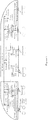
- the above control method is applied to a train as shown in Figure 1 , so that damping of the shock absorber of the train can be adjusted in a real time manner based on a traveling route condition of the train, thereby realizing a fast damping adjustment and saving manpower.
- the technical solution according to an embodiment of the present disclosure is applicable to an application scenario in which damping of a shock absorber of a train is to be adjusted.
- damping of a shock absorber of a train can be adjusted without replacing the shock absorber of the train.
- a train travels in various terrain environments. For different route conditions, damping of the shock absorber of the train is required to be adjusted. For example, when the train travels on a plain, small damping of the shock absorber is required. However, when the train travels on a continuous curved road or a continuous undulating road, large damping of the shock absorber is required so as to ensure a smooth traveling of the train.
- a common shock absorber of the train is a fixed damping shock absorber. That is, damping of the shock absorber is fixed.
- damping of the shock absorber of the train is required to be changed adaptively. The shock absorber of the train is directly replaced.
- variable damping shock absorber is a shock absorber whose damping is variable.
- damping of the variable damping shock absorber can be adjusted without replacing the shock absorber.
- the train may adjust damping of the shock absorber without replacing the shock absorber.
- a matched control device is required to be provided to control a variation of damping of the variable damping shock absorber, so as to adjust the damping of the variable damping shock absorber of the train in a real time manner based on a route condition of the train, thereby ensuring traveling stability of the train all the time.
- a method and a device for controlling damping of a shock absorber of a train are provided according to an embodiment of the present disclosure, to control and adjust damping of the variable damping shock absorber of the train as shown in Figure 1 .
- the technical solution according to the embodiment of the present disclosure is applicable to a central controller for controlling the damping of the variable damping shock absorber of the train.
- the central controller sends control instructions to the variable damping shock absorber via a security monitoring host or collects data related to the shock absorber of the train via the security monitoring host.
- the central controller may be another device that can perform damping control and data collection on the variable damping shock absorber of the train.
- the technical solution according to the embodiment of the present disclosure may be implemented by a hardware device similar to the central controller as shown in Figure 1 , a software program, or a cloud controller detached from the train and the like. Entities for implementing the technical solution according to the embodiment of the present disclosure are not strictly limited in the embodiment of the present disclosure.
- a hardware device or a software program that can exchange data with the variable damping shock absorber of the train may be used to implement the technical solution according to the embodiment of the present disclosure.
- a method for controlling damping of a shock absorber of a train is provided according to an embodiment of the present disclosure. As shown in Figure 2 , the method includes steps S201 to S203.
- step S201 lateral vibration acceleration of a train frame is collected.
- the lateral vibration acceleration of the train frame refers to lateral vibration acceleration of a chassis frame of the train body when the train is traveling.
- the security monitoring host as shown in Figure 1 has a built-in variable damping control card.
- the variable damping control card may collect the lateral vibration acceleration of the train frame in a real time manner.
- step S202 it is determined whether damping of the shock absorber of the train matches the lateral vibration acceleration of the train frame.
- the lateral vibration acceleration of the train frame is an important parameter for evaluating whether the train travels smoothly.
- the train When traveling smoothly, the train is largely free of bumps and twists. In this case, the lateral vibration acceleration of the train frame is small.
- the train body When the train travels on a bumpy road or a continuous curved road, the train body vibrates and becomes instable with bumps and curving of the road. In this case, the lateral vibration acceleration of the train frame is large.
- the shock absorber of the train is an important device for restraining instability and a vibration of the train frame.
- the damping of the shock absorber of the train restrains the instability and the vibration of the train, thereby preventing a train derailment and other serious accidents due to accumulation of the instability and the vibration.
- the damping of the shock absorber of the train is required to match an instability state and a vibration state of the train frame. That is, the damping of the shock absorber of the train is required to exactly offset the instability and the vibration of the train frame. If the damping of the shock absorber of the train is too small to offset the instability and the vibration of the train frame, the instability and the vibration of the train cannot be completely eliminated and may be incrementally accumulated during travelling of the train, finally resulting in a train derailment. If the damping of the shock absorber of the train is too large, remaining damping acts on the train frame and results in instability and vibration of the train once again after the damping of the shock absorber of the train offsets the instability and the vibration of the train frame.
- the damping of the shock absorber of the train is required to match the instability state or the vibration state of the train.
- the instability state or the vibration state of the train is expressed by the lateral vibration acceleration of the train frame. Therefore, the damping of the shock absorber of the train is required to match the lateral vibration acceleration of the train frame so as to ensure smooth traveling of the train.
- the security monitoring host determines whether the damping of the shock absorber of the train matches the lateral vibration acceleration of the train frame, thereby determining whether the train travels smoothly.
- the damping of the shock absorber of the train matches the lateral vibration acceleration of the train frame, it is indicated that the train travels smoothly. In this case, the damping of the shock absorber of the train is unnecessary to be changed. In a case that the damping of the shock absorber of the train does not match the lateral vibration acceleration of the train frame, it is indicated that the train becomes instable and vibrates. In this case, the damping of the shock absorber of the train is required to be adjusted to offset instability and vibration of the train, such that the train travels smoothly.
- the process of determining whether the damping of the shock absorber of the train matches the lateral vibration acceleration of the train frame includes steps S302 to S305.
- step S302 an instability state and a vibration state of the train are determined based on the lateral vibration acceleration of the train frame.
- the collected lateral vibration acceleration of the train frame is inputted to a predesigned fault analysis model.
- An instability state and a vibration state of the train frame may be obtained. That is, the instability state and the vibration state of the train may be obtained.
- the fault analysis model may determine the instability state and the vibration state of the train by analyzing the inputted lateral vibration acceleration of the train frame. For example, the fault analysis model may determine serpentine instability, single direction instability and free of instability of the train by analyzing the inputted lateral vibration acceleration of the train frame. In addition, the fault analysis model may determine a vibration direction, a vibration amplitude, a vibration frequency, free of vibration of the train or the like by analyzing the inputted lateral vibration acceleration of the train frame.
- the instability state and the vibration state of the train can be determined by analyzing the lateral vibration acceleration of the train frame.
- step S303 it is determined whether the train is in a serpentine instability state and/or whether a vibration amplitude of the train is greater than a predetermined amplitude.
- the instability state and the vibration amplitude of the train are recognized so as to determine whether the train is in a serpentine instability state and whether a vibration amplitude of the train is greater than a predetermined amplitude.
- whether the train travels smoothly is determined on a basis whether the train is in the serpentine instability or the vibration amplitude of the train is greater than a predetermined amplitude, thereby determining whether the damping of the shock absorber of the train matches the lateral vibration acceleration of the train frame.
- the basis for determining whether the train travels smoothly may be changed flexibly. For example, whether the train travels smoothly may be determined by determining whether the train is in a bumpy instability state or whether the vibration frequency is within a predetermined frequency range.
- step S304 is performed. That is, it is determined that the damping of the shock absorber of the train does not match the lateral vibration acceleration of the train frame.
- the damping of the shock absorber of the train does not match the lateral vibration acceleration of the train frame. If the damping of the shock absorber of the train matches the lateral vibration acceleration of the train frame, the damping of the shock absorber of the train can offset the lateral vibration acceleration of the train frame, such that the train travels smoothly.
- Step S301 and step S305 in the method embodiment shown in Figure 3 respectively correspond to step S201 and step S203 in the method embodiment shown in Figure 2 .
- step S301 and step S305 respectively correspond to step S201 and step S203 in the method embodiment shown in Figure 2 .
- steps S301 and step S305 one may refer to descriptions of the method embodiment shown in Figure 2 , and details are not repeated herein.
- step S203 is performed. That is, the damping of the variable damping shock absorber of the train is adjusted, such that the damping of the variable damping shock absorber of the train matches the lateral vibration acceleration of the train frame.
- the security monitoring host determines that the damping of the shock absorber of the train does not match the lateral vibration acceleration of the train frame based on the lateral vibration acceleration of the train frame collected by the variable damping control card, the security monitoring host sends warning information to the central controller of the train to request for adjusting the damping of the variable damping shock absorber of the train.
- the warning information may carry lateral vibration acceleration data of the train at a current time instant and current damping data of the variable damping shock absorber of the train.
- the central controller determines how to adjust the damping of the variable damping shock absorber of the train based on a magnitude relationship between the lateral vibration acceleration of the train and the variable damping shock absorber of the train, and sends a corresponding control instruction to the security monitoring host.
- the security monitoring host increases or decreases the damping of the variable damping shock absorber in response to the received control instruction, thereby adjusting the damping of the variable damping shock absorber.
- step S201 the method returns to step S201. That is, the lateral vibration acceleration of the train frame is collected, it is determined whether the damping of the shock absorber of the train matches the lateral vibration acceleration of the train frame, and the damping of the variable damping shock absorber of the train is adjusted. The above processes are repeatedly performed until the damping of the shock absorber of the train matches the lateral vibration acceleration of the train frame.
- the method for controlling damping of a shock absorber of a train further includes steps S403 to S405.
- step S403 it is determined whether the number of times of adjusting the damping of the variable damping shock absorber of the train is greater than a predetermined number of times during a predetermined duration before a current time instant.
- the predetermined duration before the current time instant refers to a duration from a time instant before the current time instant to the current time instant. For example, assuming that the current time instant is 12:00 and the predetermined duration is 30 minutes, the predetermined duration before the current time instant refers to 30 minutes from 11:30 to 12:00.
- the damping of the shock absorber of the train when it is determined that the damping of the shock absorber of the train does not match the lateral vibration acceleration of the train frame, that is, when it is determined that the damping of the shock absorber of the train is required to be adjusted, it is firstly verified that whether the number of times of adjusting the damping of the variable damping shock absorber of the train is greater than the predetermined number of times during the predetermined duration before the current time instant. That is, it is verified that whether the damping of the variable damping shock absorber of the train is adjusted frequently.
- step S404 is performed. That is, the damping of the variable damping shock absorber of the train is adjusted, such that the damping of the variable damping shock absorber of the train matches the lateral vibration acceleration of the train frame.
- step S405 is performed. That is, it is refused to adjust the damping of the variable damping shock absorber of the train.
- the damping of the variable damping shock absorber of the train is required to be adjusted.
- the damping of the variable damping shock absorber of the train is adjusted such that the damping of the variable damping shock absorber of the train matches the lateral vibration acceleration of the train frame.
- Steps S401, S402 and S404 in the embodiment respectively correspond to steps S201, S202 and S203 in the method embodiment shown in Figure 2 .
- steps S401, S402 and S404 one may refer to descriptions of the method embodiment shown in Figure 2 , and details are not repeated herein.
- the method for controlling damping of a shock absorber of a train further includes: acquiring a state of a damping switch of the variable damping shock absorber of the train so as to determine whether the damping of the variable damping shock absorber of the train is adjusted.
- variable damping shock absorber of the train is further provided with a damping switch.
- the damping switch refers to a switch that is capable of adjusting the damping of the variable damping shock absorber. When it is required to adjust the damping of the variable damping shock absorber of the train, the damping switch is firstly required to be switched on. Then the damping is adjusted.
- the damping of the variable damping shock absorber of the train cannot be adjusted.
- the damping of the variable damping shock absorber is fixed and the variable damping shock absorber functions as a fixed damping shock absorber.
- the damping switch is required to be switched on. Therefore, it can be determined whether the damping of the variable damping shock absorber of the train is adjusted by detecting the state of the damping switch of the variable damping shock absorber of the train.
- damping switch of the variable damping shock absorber of the train If the damping switch of the variable damping shock absorber of the train is in an on state, it is determined that the damping of the variable damping shock absorber of the train can be adjusted. If the damping switch of the variable damping shock absorber of the train is in an off state, it is determined that the damping of the variable damping shock absorber of the train cannot be adjusted.
- the damping switch of the variable damping shock absorber of the train is firstly controlled to be switched on; and then the damping of the variable damping shock absorber of the train is adjusted, such that the damping of the variable damping shock absorber of the train matches the lateral vibration acceleration of the train frame.
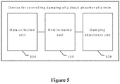
- a device for controlling damping of a shock absorber of a train is further provided according to another embodiment of the present disclosure. As shown in Figure 5 , the device includes a data collection unit 100, a determination unit 110 and a damping adjustment unit 120.
- the data collection unit 100 is configured to collect lateral vibration acceleration of a train frame.
- the determination unit 110 is configured to determine whether damping of a shock absorber of a train matches the lateral vibration acceleration of the train frame.
- the damping adjustment unit 120 is configured to adjust, in a case that the damping of the shock absorber of the train does not match the lateral vibration acceleration of the train frame, damping of a variable damping shock absorber of the train, such that the damping of the variable damping shock absorber of the train matches the lateral vibration acceleration of the train frame.
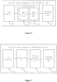
- the determination unit 110 includes a state recognition unit 1101 and a state analysis unit 1102.
- the state recognition unit 1101 is configured to determine an instability state and a vibration state of the train based on the lateral vibration acceleration of the train frame.
- the state analysis unit 1102 is configured to determine, when the train is in a serpentine instability state and/or a vibration amplitude of the train is greater than a predetermined amplitude, that the damping of the shock absorber of the train does not match the lateral vibration acceleration of the train frame.
- the device further includes a damping adjustment determination unit 130.
- the damping adjustment determination unit 130 is configured to determine whether the number of times of adjusting the damping of the variable damping shock absorber of the train is greater than a predetermined number of times during a predetermined duration before a current time instant.
- the damping adjustment unit 120 adjusts the damping of the variable damping shock absorber of the train, such that the damping of the variable damping shock absorber of the train matches the lateral vibration acceleration of the train frame.
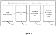
- the device further includes a damping adjustment verification unit 140.
- the damping adjustment verification unit 140 is configured to acquire a state of a damping switch of the variable damping shock absorber of the train so as to determine whether the damping of the variable damping shock absorber of the train is adjusted.
- the device further includes a damping switch control unit.
- the damping switch control unit is configured to control the damping switch of the variable damping shock absorber of the train to be switched on.
- the damping adjustment unit 120 adjusts the damping of the variable damping shock absorber of the train, such that the damping of the variable damping shock absorber of the train matches the lateral vibration acceleration of the train frame.
- the software unit may be arranged in a random access memory (RAM), an internal storage, a read-only memory (ROM), an electrically programmable ROM, an electrically erasable programmable ROM, a register, a hard disk, a removable disk, a CD-ROM or any other form of storage medium known in the art.
- RAM random access memory
- ROM read-only memory
- EEPROM electrically programmable ROM
- erasable programmable ROM electrically erasable programmable ROM
- register a hard disk, a removable disk, a CD-ROM or any other form of storage medium known in the art.
Landscapes
- Engineering & Computer Science (AREA)
- Mechanical Engineering (AREA)
- Vehicle Body Suspensions (AREA)
- Vibration Prevention Devices (AREA)
Abstract
Description
- The present application claims priority to
Chinese Patent Application No.201811480709.0 - The present disclosure relates to the technical field of train traveling control, and in particular to a method and a device for controlling damping of a shock absorber of a train.
- At present, a shock absorber of a bogie of a high speed motor train unit is a fixed damping shock absorber. When a train is traveling and a travelling route condition of the train changes, damping of a shock absorber of the train is required to be adjusted. Thus, it is required to replace shock absorbers of the train in batches, such that damping of shock absorbers matches the changed route condition.
- Adjusting damping of the shock absorber of the train by replacing the shock absorber of the train in batches consumes a lot of manpower costs and results in low efficiency of damping adjustment.
- Based on the above defects and disadvantages in conventional technologies, a method and a device for controlling damping of a shock absorber of a train are provided according to the present disclosure to automatically adjust damping of the shock absorber of the train, thereby improving efficiency of damping adjustment.
- The method for controlling damping of a shock absorber of a train includes:
- collecting lateral vibration acceleration of a train frame,
- determining whether the damping of the shock absorber of the train matches the lateral vibration acceleration of the train frame, and
- adjusting, in a case that the damping of the shock absorber of the train does not match the lateral vibration acceleration of the train frame, damping of a variable damping shock absorber of the train, such that the damping of the variable damping shock absorber of the train matches the lateral vibration acceleration of the train frame.
- In an embodiment, the determining whether the damping of the shock absorber of the train matches the lateral vibration acceleration of the train frame includes:
- determining an instability state and a vibration state of the train based on the lateral vibration acceleration of the train frame; and
- determining, when the train is in a serpentine instability state and/or a vibration amplitude of the train is greater than a predetermined amplitude, that the damping of the shock absorber of the train does not match the lateral vibration acceleration of the train frame.
- In an embodiment, in a case that it is determined that the damping of the shock absorber of the train does not match the lateral vibration acceleration of the train frame, the method further includes:
- determining whether the number of times of adjusting the damping of the variable damping shock absorber of the train is greater than a predetermined number of times during a predetermined duration before a current time instant; and
- adjusting, if the number of times of adjusting the damping of the variable damping shock absorber of the train is not greater than the predetermined number of times, the damping of the variable damping shock absorber of the train, such that the damping of the variable damping shock absorber of the train matches the lateral vibration acceleration of the train frame.
- In an embodiment, the method further includes:
acquiring a state of a damping switch of the variable damping shock absorber of the train, so as to determine whether the damping of the variable damping shock absorber of the train is adjusted. - In an embodiment, in a case that the damping switch of the variable damping shock absorber of the train is in an off state, the method further includes:
- controlling the damping switch of the variable damping shock absorber of the train to be switched on; and
- adjusting the damping of the variable damping shock absorber of the train, such that the damping of the variable damping shock absorber of the train matches the lateral vibration acceleration of the train frame.
- The device for controlling damping of a shock absorber of a train includes a data collection unit, a determination unit and a damping adjustment unit.
- The data collection unit is configured to collect lateral vibration acceleration of a train frame.
- The determination unit is configured to determine whether damping of a shock absorber of a train matches the lateral vibration acceleration of the train frame.
- The damping adjustment unit is configured to adjust, in a case that the damping of the shock absorber of the train does not match the lateral vibration acceleration of the train frame, damping of a variable damping shock absorber of the train, such that the damping of the variable damping shock absorber of the train matches the lateral vibration acceleration of the train frame.
- In an embodiment, the determination unit includes a state recognition unit and a state analysis unit.
- The state recognition unit is configured to determine an instability state and a vibration state of the train based on the lateral vibration acceleration of the train frame.
- The state analysis unit is configured to determine, when the train is in a serpentine instability state and/or a vibration amplitude of the train is greater than a predetermined amplitude, that the damping of the shock absorber of the train does not match the lateral vibration acceleration of the train frame.
- In an embodiment, the device further includes a damping adjustment determination unit.
- The damping adjustment determination unit is configured to determine whether the number of times of adjusting the damping of the variable damping shock absorber of the train is greater than a predetermined number of times during a predetermined duration before a current time instant.
- In an embodiment, the device further includes a damping adjustment verification unit.
- The damping adjustment verification unit is configured to acquire a state of a damping switch of the variable damping shock absorber of the train so as to determine whether the damping of the variable damping shock absorber of the train is adjusted.
- In an embodiment, the device further includes a damping switch control unit.
- The damping switch control unit is configured to control the damping switch of the variable damping shock absorber of the train to be switched on.
- With the method for controlling damping of a shock absorber of a train according to the present disclosure, whether it is required to adjust damping of a variable damping shock absorber of the train can be determined by automatically collecting data. The damping of the variable damping shock absorber of the train is automatically adjusted when the damping is required to be adjusted. The above control method is applied to a train as shown in
Figure 1 , so that damping of the shock absorber of the train can be adjusted in a real time manner based on a traveling route condition of the train, thereby realizing a fast damping adjustment and saving manpower. - In order to more clearly describe the technical solutions in the embodiments of the present disclosure or the technical solutions in the conventional technology, drawings to be used in the description of the embodiments of the present disclosure or the conventional technology are briefly described hereinafter. It is apparent that the drawings described below show merely the embodiments of the present disclosure, and those skilled in the art may obtain other drawings according to the provided drawings without any creative effort.
-
Figure 1 is a schematic structural diagram of a variable damping shock absorption system of a train according to an embodiment of the present disclosure; -
Figure 2 is a schematic flowchart of a method for controlling damping of a shock absorber of a train according to an embodiment of the present disclosure; -
Figure 3 is a schematic flowchart of another method for controlling damping of a shock absorber of a train according to an embodiment of the present disclosure; -
Figure 4 is a schematic flowchart of another method for controlling damping of a shock absorber of a train according to an embodiment of the present disclosure; -
Figure 5 is a schematic structural diagram of a device for controlling damping of a shock absorber of a train according to an embodiment of the present disclosure; -
Figure 6 is a schematic structural diagram of another device for controlling damping of a shock absorber of a train according to an embodiment of the present disclosure; -
Figure 7 is a schematic structural diagram of another device for controlling damping of a shock absorber of a train according to an embodiment of the present disclosure; and -
Figure 8 is a schematic structural diagram of another device for controlling damping of a shock absorber of a train according to an embodiment of the present disclosure. - The technical solution according to an embodiment of the present disclosure is applicable to an application scenario in which damping of a shock absorber of a train is to be adjusted. With the technical solution according to the embodiment of the present disclosure, damping of a shock absorber of a train can be adjusted without replacing the shock absorber of the train.
- A train travels in various terrain environments. For different route conditions, damping of the shock absorber of the train is required to be adjusted. For example, when the train travels on a plain, small damping of the shock absorber is required. However, when the train travels on a continuous curved road or a continuous undulating road, large damping of the shock absorber is required so as to ensure a smooth traveling of the train.
- Therefore, when a train is traveling and a route condition changes, it is required to adjust damping of the shock absorber of the train, such that the damping of the shock absorber of the train matches a traveling demand of the train. However, at present, a common shock absorber of the train is a fixed damping shock absorber. That is, damping of the shock absorber is fixed. When the traveling route of the train changes, damping of the shock absorber of the train is required to be changed adaptively. The shock absorber of the train is directly replaced.
- Replacing shock absorbers of a train in batches requires a lot of manual labors. In addition, manually replacing shock absorbers of the train consumes a lot of time, resulting in low adjustment efficiency of the damping of the shock absorber of the train.
- In order to solve the above problem, the fixed damping shock absorber is replaced with a variable damping shock absorber according to the present disclosure. Just as its name implies, the variable damping shock absorber is a shock absorber whose damping is variable. When the variable damping shock absorber is applied to a train, damping of the variable damping shock absorber can be adjusted without replacing the shock absorber.
- As shown in
Figure 1 , when the variable damping shock absorber is applied to a train, the train may adjust damping of the shock absorber without replacing the shock absorber. Based on this, a matched control device is required to be provided to control a variation of damping of the variable damping shock absorber, so as to adjust the damping of the variable damping shock absorber of the train in a real time manner based on a route condition of the train, thereby ensuring traveling stability of the train all the time. - Based on the above requirements, a method and a device for controlling damping of a shock absorber of a train are provided according to an embodiment of the present disclosure, to control and adjust damping of the variable damping shock absorber of the train as shown in
Figure 1 . - It should be noted that, as shown in
Figure 1 , the technical solution according to the embodiment of the present disclosure is applicable to a central controller for controlling the damping of the variable damping shock absorber of the train. The central controller sends control instructions to the variable damping shock absorber via a security monitoring host or collects data related to the shock absorber of the train via the security monitoring host. When the technical solution according to the embodiment of the present disclosure is implemented, the central controller may be another device that can perform damping control and data collection on the variable damping shock absorber of the train. - Further, the technical solution according to the embodiment of the present disclosure may be implemented by a hardware device similar to the central controller as shown in
Figure 1 , a software program, or a cloud controller detached from the train and the like. Entities for implementing the technical solution according to the embodiment of the present disclosure are not strictly limited in the embodiment of the present disclosure. Theoretically, a hardware device or a software program that can exchange data with the variable damping shock absorber of the train may be used to implement the technical solution according to the embodiment of the present disclosure. - Technical solutions of embodiments of the present disclosure are clearly and completely described below in conjunction with the drawings of the embodiments of the present disclosure. Apparently, the embodiments described in the following are only some embodiments of the present disclosure, rather than all the embodiments. Any other embodiments obtained by those skilled in the art based on the embodiments in the present disclosure without any creative effort fall within the protection scope of the present disclosure.
- A method for controlling damping of a shock absorber of a train is provided according to an embodiment of the present disclosure. As shown in
Figure 2 , the method includes steps S201 to S203. - In step S201, lateral vibration acceleration of a train frame is collected.
- The lateral vibration acceleration of the train frame refers to lateral vibration acceleration of a chassis frame of the train body when the train is traveling.
- The security monitoring host as shown in
Figure 1 has a built-in variable damping control card. The variable damping control card may collect the lateral vibration acceleration of the train frame in a real time manner. - In step S202, it is determined whether damping of the shock absorber of the train matches the lateral vibration acceleration of the train frame.
- The lateral vibration acceleration of the train frame is an important parameter for evaluating whether the train travels smoothly. When traveling smoothly, the train is largely free of bumps and twists. In this case, the lateral vibration acceleration of the train frame is small. When the train travels on a bumpy road or a continuous curved road, the train body vibrates and becomes instable with bumps and curving of the road. In this case, the lateral vibration acceleration of the train frame is large.
- In addition, the shock absorber of the train is an important device for restraining instability and a vibration of the train frame. When the train becomes instable and vibrates, the damping of the shock absorber of the train restrains the instability and the vibration of the train, thereby preventing a train derailment and other serious accidents due to accumulation of the instability and the vibration.
- Theoretically, the damping of the shock absorber of the train is required to match an instability state and a vibration state of the train frame. That is, the damping of the shock absorber of the train is required to exactly offset the instability and the vibration of the train frame. If the damping of the shock absorber of the train is too small to offset the instability and the vibration of the train frame, the instability and the vibration of the train cannot be completely eliminated and may be incrementally accumulated during travelling of the train, finally resulting in a train derailment. If the damping of the shock absorber of the train is too large, remaining damping acts on the train frame and results in instability and vibration of the train once again after the damping of the shock absorber of the train offsets the instability and the vibration of the train frame.
- It is understandable that the damping of the shock absorber of the train is required to match the instability state or the vibration state of the train. The instability state or the vibration state of the train is expressed by the lateral vibration acceleration of the train frame. Therefore, the damping of the shock absorber of the train is required to match the lateral vibration acceleration of the train frame so as to ensure smooth traveling of the train.
- Therefore, when the lateral vibration acceleration of the train frame during train traveling is collected, the security monitoring host determines whether the damping of the shock absorber of the train matches the lateral vibration acceleration of the train frame, thereby determining whether the train travels smoothly.
- In a case that the damping of the shock absorber of the train matches the lateral vibration acceleration of the train frame, it is indicated that the train travels smoothly. In this case, the damping of the shock absorber of the train is unnecessary to be changed. In a case that the damping of the shock absorber of the train does not match the lateral vibration acceleration of the train frame, it is indicated that the train becomes instable and vibrates. In this case, the damping of the shock absorber of the train is required to be adjusted to offset instability and vibration of the train, such that the train travels smoothly.
- Based on the above descriptions, it can be understood that whether the damping of the shock absorber of the train matches the lateral vibration acceleration of the train frame can be characterized by whether the train becomes instable and vibrates. Based on this, a specific implementation for determining whether the damping of the shock absorber of the train matches the lateral vibration acceleration of the train frame is provided according to another embodiment of the present disclosure.
- As shown in
Figure 3 , the process of determining whether the damping of the shock absorber of the train matches the lateral vibration acceleration of the train frame according to an embodiment of the present disclosure includes steps S302 to S305. - In step S302, an instability state and a vibration state of the train are determined based on the lateral vibration acceleration of the train frame.
- The collected lateral vibration acceleration of the train frame is inputted to a predesigned fault analysis model. An instability state and a vibration state of the train frame may be obtained. That is, the instability state and the vibration state of the train may be obtained.
- The fault analysis model may determine the instability state and the vibration state of the train by analyzing the inputted lateral vibration acceleration of the train frame. For example, the fault analysis model may determine serpentine instability, single direction instability and free of instability of the train by analyzing the inputted lateral vibration acceleration of the train frame. In addition, the fault analysis model may determine a vibration direction, a vibration amplitude, a vibration frequency, free of vibration of the train or the like by analyzing the inputted lateral vibration acceleration of the train frame.
- It can be understood that by using the fault analysis model, the instability state and the vibration state of the train can be determined by analyzing the lateral vibration acceleration of the train frame.
- It should be noted that if it is determined that the train does not become instable and vibrate by analysis of the fault analysis model, it is indicated that the train travels smoothly. In this case, subsequent analysis and processing are not performed. The lateral vibration acceleration of the train frame is collected once again, and it is determined whether the damping of the shock absorber of the train matches the lateral vibration acceleration of the train frame once again.
- In step S303, it is determined whether the train is in a serpentine instability state and/or whether a vibration amplitude of the train is greater than a predetermined amplitude.
- The instability state and the vibration amplitude of the train are recognized so as to determine whether the train is in a serpentine instability state and whether a vibration amplitude of the train is greater than a predetermined amplitude.
- It should be noted that in the embodiment of the present disclosure, whether the train travels smoothly is determined on a basis whether the train is in the serpentine instability or the vibration amplitude of the train is greater than a predetermined amplitude, thereby determining whether the damping of the shock absorber of the train matches the lateral vibration acceleration of the train frame.
- When the technical solution according to an embodiment of the present disclosure is implemented, the basis for determining whether the train travels smoothly may be changed flexibly. For example, whether the train travels smoothly may be determined by determining whether the train is in a bumpy instability state or whether the vibration frequency is within a predetermined frequency range.
- When the train is in a serpentine instability state and/or the vibration amplitude of the train is greater than a predetermined amplitude, step S304 is performed. That is, it is determined that the damping of the shock absorber of the train does not match the lateral vibration acceleration of the train frame.
- When the train is in the serpentine instability state and/or the vibration amplitude of the train is greater than the predetermined amplitude, it is determined that the damping of the shock absorber of the train does not match the lateral vibration acceleration of the train frame. If the damping of the shock absorber of the train matches the lateral vibration acceleration of the train frame, the damping of the shock absorber of the train can offset the lateral vibration acceleration of the train frame, such that the train travels smoothly.
- Step S301 and step S305 in the method embodiment shown in
Figure 3 respectively correspond to step S201 and step S203 in the method embodiment shown inFigure 2 . For details of step S301 and step S305, one may refer to descriptions of the method embodiment shown inFigure 2 , and details are not repeated herein. - When the damping of the shock absorber of the train does not match the lateral vibration acceleration of the train frame, step S203 is performed. That is, the damping of the variable damping shock absorber of the train is adjusted, such that the damping of the variable damping shock absorber of the train matches the lateral vibration acceleration of the train frame.
- When the security monitoring host determines that the damping of the shock absorber of the train does not match the lateral vibration acceleration of the train frame based on the lateral vibration acceleration of the train frame collected by the variable damping control card, the security monitoring host sends warning information to the central controller of the train to request for adjusting the damping of the variable damping shock absorber of the train.
- The warning information may carry lateral vibration acceleration data of the train at a current time instant and current damping data of the variable damping shock absorber of the train.
- As shown in
Figure 1 , when the warning information is received, the central controller determines how to adjust the damping of the variable damping shock absorber of the train based on a magnitude relationship between the lateral vibration acceleration of the train and the variable damping shock absorber of the train, and sends a corresponding control instruction to the security monitoring host. - The security monitoring host increases or decreases the damping of the variable damping shock absorber in response to the received control instruction, thereby adjusting the damping of the variable damping shock absorber.
- Further, after the damping of the variable damping shock absorber of the train is adjusted once, the method returns to step S201. That is, the lateral vibration acceleration of the train frame is collected, it is determined whether the damping of the shock absorber of the train matches the lateral vibration acceleration of the train frame, and the damping of the variable damping shock absorber of the train is adjusted. The above processes are repeatedly performed until the damping of the shock absorber of the train matches the lateral vibration acceleration of the train frame.
- It can be seen from the above that with the method for controlling damping of a shock absorber of a train according to the embodiments of the present disclosure, whether it is required to adjust damping of the variable damping shock absorber of the train can be determined by automatically collecting data and the damping of the variable damping shock absorber of the train is automatically adjusted when the damping is required to be adjusted. When the above control method is applied to the train as shown in
Figure 1 , the damping of the shock absorber of the train can be adjusted in a real time manner based on a traveling route condition of the train, thereby realizing a fast damping adjustment and saving manpower. - According to another embodiment of the present disclosure, as shown in
Figure 4 , in a case that it is determined that the damping of the shock absorber of the train does not match the lateral vibration acceleration of the train frame, the method for controlling damping of a shock absorber of a train further includes steps S403 to S405. - In step S403, it is determined whether the number of times of adjusting the damping of the variable damping shock absorber of the train is greater than a predetermined number of times during a predetermined duration before a current time instant.
- The predetermined duration before the current time instant refers to a duration from a time instant before the current time instant to the current time instant. For example, assuming that the current time instant is 12:00 and the predetermined duration is 30 minutes, the predetermined duration before the current time instant refers to 30 minutes from 11:30 to 12:00.
- In the embodiment of the present disclosure, when it is determined that the damping of the shock absorber of the train does not match the lateral vibration acceleration of the train frame, that is, when it is determined that the damping of the shock absorber of the train is required to be adjusted, it is firstly verified that whether the number of times of adjusting the damping of the variable damping shock absorber of the train is greater than the predetermined number of times during the predetermined duration before the current time instant. That is, it is verified that whether the damping of the variable damping shock absorber of the train is adjusted frequently.
- If the number of times of adjusting the damping of the variable damping shock absorber of the train is no greater than the predetermined number of times, step S404 is performed. That is, the damping of the variable damping shock absorber of the train is adjusted, such that the damping of the variable damping shock absorber of the train matches the lateral vibration acceleration of the train frame.
- If the number of times of adjusting the damping of the variable damping shock absorber of the train is greater than the predetermined number of times, step S405 is performed. That is, it is refused to adjust the damping of the variable damping shock absorber of the train.
- If it is verified that the number of times of adjusting the damping of the variable damping shock absorber of the train is greater than the predetermined number of times during the predetermined duration before the current time instant, that is, the damping of the variable damping shock absorber of the train is adjusted frequently, it is considered that an instruction for adjusting damping of the variable damping shock absorber of the train is mistakenly transmitted in this case. Therefore, it is refused to adjust the damping of the variable damping shock absorber of the train or an error report is sent to staff to remind the staff of dealing with the error report.
- On the contrary, if the number of times of adjusting the damping of the variable damping shock absorber of the train is not greater than the predetermined number of times during the predetermined duration before the current time instant, it may be determined that the damping of the variable damping shock absorber of the train is required to be adjusted. In this case, in response to the requirement, the damping of the variable damping shock absorber of the train is adjusted such that the damping of the variable damping shock absorber of the train matches the lateral vibration acceleration of the train frame.
- Steps S401, S402 and S404 in the embodiment respectively correspond to steps S201, S202 and S203 in the method embodiment shown in
Figure 2 . For details of steps S401, S402 and S404, one may refer to descriptions of the method embodiment shown inFigure 2 , and details are not repeated herein. - According to another embodiment of the present disclosure, after the damping of the variable damping shock absorber of the train is adjusted, the method for controlling damping of a shock absorber of a train further includes:
acquiring a state of a damping switch of the variable damping shock absorber of the train so as to determine whether the damping of the variable damping shock absorber of the train is adjusted. - In the embodiment of the present disclosure, the variable damping shock absorber of the train is further provided with a damping switch. The damping switch refers to a switch that is capable of adjusting the damping of the variable damping shock absorber. When it is required to adjust the damping of the variable damping shock absorber of the train, the damping switch is firstly required to be switched on. Then the damping is adjusted.
- When the damping switch is in an off state, the damping of the variable damping shock absorber of the train cannot be adjusted. In this case, the damping of the variable damping shock absorber is fixed and the variable damping shock absorber functions as a fixed damping shock absorber.
- It can be understood that in order to adjust the damping of the variable damping shock absorber of the train, the damping switch is required to be switched on. Therefore, it can be determined whether the damping of the variable damping shock absorber of the train is adjusted by detecting the state of the damping switch of the variable damping shock absorber of the train.
- If the damping switch of the variable damping shock absorber of the train is in an on state, it is determined that the damping of the variable damping shock absorber of the train can be adjusted. If the damping switch of the variable damping shock absorber of the train is in an off state, it is determined that the damping of the variable damping shock absorber of the train cannot be adjusted.
- Further, if it is detected that the damping switch of the variable damping shock absorber of the train is in an off state, it is determined that it fails to send a damping adjustment control instruction to the security monitoring host for instructing to adjust the damping of the variable damping shock absorber of the train.
- In order to effectively adjust the damping of the variable damping shock absorber of the train, in the embodiment of the present disclosure, the damping switch of the variable damping shock absorber of the train is firstly controlled to be switched on; and then the damping of the variable damping shock absorber of the train is adjusted, such that the damping of the variable damping shock absorber of the train matches the lateral vibration acceleration of the train frame.
- A device for controlling damping of a shock absorber of a train is further provided according to another embodiment of the present disclosure. As shown in
Figure 5 , the device includes adata collection unit 100, adetermination unit 110 and a dampingadjustment unit 120. - The
data collection unit 100 is configured to collect lateral vibration acceleration of a train frame. - The
determination unit 110 is configured to determine whether damping of a shock absorber of a train matches the lateral vibration acceleration of the train frame. - The damping
adjustment unit 120 is configured to adjust, in a case that the damping of the shock absorber of the train does not match the lateral vibration acceleration of the train frame, damping of a variable damping shock absorber of the train, such that the damping of the variable damping shock absorber of the train matches the lateral vibration acceleration of the train frame. - In another embodiment of the present disclosure, as shown in
Figure 6 , thedetermination unit 110 includes astate recognition unit 1101 and astate analysis unit 1102. - The
state recognition unit 1101 is configured to determine an instability state and a vibration state of the train based on the lateral vibration acceleration of the train frame. - The
state analysis unit 1102 is configured to determine, when the train is in a serpentine instability state and/or a vibration amplitude of the train is greater than a predetermined amplitude, that the damping of the shock absorber of the train does not match the lateral vibration acceleration of the train frame. - In another embodiment of the present disclosure, as shown in
Figure 7 , the device further includes a dampingadjustment determination unit 130. - The damping
adjustment determination unit 130 is configured to determine whether the number of times of adjusting the damping of the variable damping shock absorber of the train is greater than a predetermined number of times during a predetermined duration before a current time instant. - In a case that the number of times of adjusting the damping of the variable damping shock absorber of the train is not greater than the predetermined number of times, the damping
adjustment unit 120 adjusts the damping of the variable damping shock absorber of the train, such that the damping of the variable damping shock absorber of the train matches the lateral vibration acceleration of the train frame. - In another embodiment of the present disclosure, as shown in
Figure 8 , the device further includes a dampingadjustment verification unit 140. - The damping
adjustment verification unit 140 is configured to acquire a state of a damping switch of the variable damping shock absorber of the train so as to determine whether the damping of the variable damping shock absorber of the train is adjusted. - In another embodiment of the present disclosure, the device further includes a damping switch control unit.
- The damping switch control unit is configured to control the damping switch of the variable damping shock absorber of the train to be switched on. On the basis of the above, the damping
adjustment unit 120 adjusts the damping of the variable damping shock absorber of the train, such that the damping of the variable damping shock absorber of the train matches the lateral vibration acceleration of the train frame. - For specific operations of various units of the device for adjusting damping of the shock absorber of the train, one may refer to the description of the above method embodiments, and details are not repeated herein.
- It should be noted that the embodiments in this specification are described in a progressive way, each of which emphasizes the differences from others, and for the same or similar parts among the embodiments, one may refer to description of other embodiments. Since the device disclosed in the embodiments is basically similar to the method therein, the description thereof is relatively simple, and for relevant matters, one may refer to the description of the method embodiments.
- It should be further understood by those skilled in the art that units and algorithm steps in each example described in combination with the disclosed embodiments may be implemented by electronic hardware, computer software or a combination thereof. In order to clearly describe interchangeability of the hardware and the software, the units and steps in each example are generally described above based on functions. Whether the functions are realized by the hardware or the software is determined by specific applications of the technical solutions and design constraints. For each of the specific applications, those skilled in the art may adopt a specific implementation to realize the functions described above, and the implementation should fall within the scope of the present disclosure.
- Methods or steps of algorithm described in combination with the disclosed embodiments may be directly implemented by hardware, a software unit executed by a processor or a combination thereof. The software unit may be arranged in a random access memory (RAM), an internal storage, a read-only memory (ROM), an electrically programmable ROM, an electrically erasable programmable ROM, a register, a hard disk, a removable disk, a CD-ROM or any other form of storage medium known in the art.
- Finally, it should be noted that in the present disclosure, relational terms such as "first" and "second" are merely used to distinguish one entity or operation from another entity or operation, but do not indicate or imply an actual relationship or order of these entities or operations. In addition, terms of "include", "comprise" or any other variants are intended to be non-exclusive. Therefore, a process, method, article or equipment including multiple elements includes not only the elements but also other elements that are not enumerated, or also include the elements inherent for the process, method, article or equipment. Unless expressively limited otherwise, the statement "comprising (including) one..." does not exclude the case that other similar elements may exist in the process, method, article or equipment.
- With the description of the embodiments disclosed above, those skilled in the art may implement or use technical solutions of the present disclosure. Numerous modifications to the embodiments are apparent to those skilled in the art, and the general principles defined herein may be implemented in other embodiments without departing from the spirit or scope of the present disclosure. Therefore, the present disclosure is not limited to the embodiments described herein, but should comply with the widest scope consistent with the principles and novel features disclosed herein.
Claims (10)
- A method for controlling damping of a shock absorber of a train, comprising:collecting lateral vibration acceleration of a train frame;determining whether the damping of the shock absorber of the train matches the lateral vibration acceleration of the train frame; andadjusting, in a case that the damping of the shock absorber of the train does not match the lateral vibration acceleration of the train frame, damping of a variable damping shock absorber of the train, wherein the damping of the variable damping shock absorber of the train matches the lateral vibration acceleration of the train frame.
- The method according to claim 1, wherein the determining whether the damping of the shock absorber of the train matches the lateral vibration acceleration of the train frame comprises:determining an instability state and a vibration state of the train based on the lateral vibration acceleration of the train frame; anddetermining, when the train is in a serpentine instability state and/or a vibration amplitude of the train is greater than a predetermined amplitude, that the damping of the shock absorber of the train does not match the lateral vibration acceleration of the train frame.
- The method according to claim 1 or claim 2, wherein in a case that it is determined that the damping of the shock absorber of the train does not match the lateral vibration acceleration of the train frame, the method further comprises:determining whether the number of times of adjusting the damping of the variable damping shock absorber of the train is greater than a predetermined number of times during a predetermined duration before a current time instant; andadjusting, if the number of times of adjusting the damping of the variable damping shock absorber of the train is not greater than the predetermined number of times, the damping of the variable damping shock absorber of the train, wherein the damping of the variable damping shock absorber of the train matches the lateral vibration acceleration of the train frame.
- The method according to claim 1 or claim 2, further comprising:
acquiring a state of a damping switch of the variable damping shock absorber of the train so as to determine whether the damping of the variable damping shock absorber of the train is adjusted. - The method according to claim 4, wherein in a case that the damping switch of the variable damping shock absorber of the train is in an off state, the method further comprises:controlling the damping switch of the variable damping shock absorber of the train to be switched on; andadjusting the damping of the variable damping shock absorber of the train, wherein the damping of the variable damping shock absorber of the train matches the lateral vibration acceleration of the train frame.
- A device for controlling damping of a shock absorber of a train, comprising:a data collection unit configured to collect lateral vibration acceleration of a train frame;a determination unit configured to determine whether the damping of the shock absorber of the train matches the lateral vibration acceleration of the train frame; anda damping adjustment unit configured to adjust, in a case that the damping of the shock absorber of the train does not match the lateral vibration acceleration of the train frame, damping of a variable damping shock absorber of the train, wherein the damping of the variable damping shock absorber of the train matches the lateral vibration acceleration of the train frame.
- The device according to claim 6, wherein the determination unit comprises:a state recognition unit configured to determine an instability state and a vibration state of the train based on the lateral vibration acceleration of the train frame; anda state analysis unit configured to determine, when the train is in a serpentine instability state and/or a vibration amplitude of the train is greater than a predetermined amplitude, that the damping of the shock absorber of the train does not match the lateral vibration acceleration of the train frame.
- The device according to claim 6 or claim 7, further comprising:
a damping adjustment determination unit configured to determine whether the number of times of adjusting the damping of the variable damping shock absorber of the train is greater than a predetermined number of times during a predetermined duration before a current time instant. - The device according to claim 6 or claim 7, further comprising:
a damping adjustment verification unit configured to acquire a state of a damping switch of the variable damping shock absorber of the train so as to determine whether the damping of the variable damping shock absorber of the train is adjusted. - The device according to claim 9, further comprising:
a damping switch control unit configured to control the damping switch of the variable damping shock absorber of the train to be switched on.
Priority Applications (1)
| Application Number | Priority Date | Filing Date | Title |
|---|---|---|---|
| RS20240004A RS65030B1 (en) | 2018-12-05 | 2019-11-11 | Damping control method and device for shock absorber of train |
Applications Claiming Priority (2)
| Application Number | Priority Date | Filing Date | Title |
|---|---|---|---|
| CN201811480709.0A CN110539770B (en) | 2018-12-05 | 2018-12-05 | Train shock absorber damping control method and device |
| PCT/CN2019/117093 WO2020114205A1 (en) | 2018-12-05 | 2019-11-11 | Damping control method and device for shock absorber of train |
Publications (3)
| Publication Number | Publication Date |
|---|---|
| EP3892516A1 true EP3892516A1 (en) | 2021-10-13 |
| EP3892516A4 EP3892516A4 (en) | 2022-08-24 |
| EP3892516B1 EP3892516B1 (en) | 2023-11-01 |
Family
ID=68702006
Family Applications (1)
| Application Number | Title | Priority Date | Filing Date |
|---|---|---|---|
| EP19893822.7A Active EP3892516B1 (en) | 2018-12-05 | 2019-11-11 | Damping control method and device for shock absorber of train |
Country Status (7)
| Country | Link |
|---|---|
| EP (1) | EP3892516B1 (en) |
| CN (1) | CN110539770B (en) |
| HU (1) | HUE064239T2 (en) |
| MY (1) | MY206485A (en) |
| RS (1) | RS65030B1 (en) |
| SG (1) | SG11202008043SA (en) |
| WO (1) | WO2020114205A1 (en) |
Families Citing this family (3)
| Publication number | Priority date | Publication date | Assignee | Title |
|---|---|---|---|---|
| CN112678010B (en) * | 2021-01-12 | 2022-03-01 | 中车青岛四方机车车辆股份有限公司 | Rail vehicle and control method and system thereof |
| CN114771593B (en) * | 2021-10-09 | 2023-08-18 | 合肥工业大学 | Anti-snaking railway vehicle vibration reduction system |
| CN117975924B (en) * | 2024-03-15 | 2024-10-15 | 深圳市双禹王声屏障工程技术有限公司 | Sound insulation method and device of integrated photovoltaic sound insulation barrier and sound insulation equipment |
Family Cites Families (17)
| Publication number | Priority date | Publication date | Assignee | Title |
|---|---|---|---|---|
| IT1216147B (en) * | 1988-03-18 | 1990-02-22 | Socimi | DEVICE FOR THE CONTROL OF DYNAMIC STRESSES TRANSMITTED FROM THE ROLLING SURFACE TO THE CASE OF A VEHICLE, IN PARTICULAR A RAILWAY VEHICLE. |
| GB9015109D0 (en) * | 1990-07-09 | 1990-08-29 | Gec Alsthom Ltd | Damping arrangements |
| DE19512437A1 (en) * | 1995-04-03 | 1996-10-10 | Rexroth Mannesmann Gmbh | Device for compensating the lateral force acting on a rail vehicle |
| DE10157368A1 (en) * | 2001-11-23 | 2003-06-12 | Bombardier Transp Gmbh | Position adjustment of a vehicle body |
| JP4514520B2 (en) * | 2004-06-02 | 2010-07-28 | 株式会社日立製作所 | Adaptive vehicle travel control system and adaptive vehicle travel control method |
| CN201272361Y (en) * | 2008-09-12 | 2009-07-15 | 南车四方机车车辆股份有限公司 | Semi-active shock-absorbing device of rail vehicle |
| DE102009053801B4 (en) * | 2009-11-18 | 2019-03-21 | Knorr-Bremse Systeme für Schienenfahrzeuge GmbH | Method and device for condition monitoring at least one wheelset bogie of a rail vehicle |
| CN202115536U (en) * | 2011-05-11 | 2012-01-18 | 铁道部运输局 | Full-active control vibration damping device of railway vehicle |
| ES2446766B1 (en) * | 2012-08-07 | 2014-11-05 | Construcciones Y Auxiliar De Ferrocarriles, S.A. | RAILWAY VEHICLE STABILIZATION SYSTEM IN DEGRADED SUSPENSION CONDITIONS |
| JP6053602B2 (en) * | 2013-04-26 | 2016-12-27 | 日立オートモティブシステムズ株式会社 | Hydraulic buffer |
| CN103674582B (en) * | 2013-11-29 | 2016-08-17 | 中车青岛四方机车车辆股份有限公司 | Movement stability of railway vehicle bogie determination methods and device |
| JP6450278B2 (en) * | 2015-08-03 | 2019-01-09 | Kyb株式会社 | Vibration control device for railway vehicles |
| CN105890744B (en) * | 2016-03-30 | 2019-05-21 | 中车青岛四方机车车辆股份有限公司 | A method for determining the serpentine instability of rail vehicles |
| CN106080643B (en) * | 2016-08-01 | 2018-05-18 | 西南交通大学 | A kind of bogie frame oscillation crosswise control device |
| JP6231634B1 (en) * | 2016-09-09 | 2017-11-15 | Kyb株式会社 | Vibration control device for railway vehicles |
| CN107054395B (en) * | 2017-03-21 | 2019-10-18 | 中车山东机车车辆有限公司 | A kind of active control type actuator and bogie |
| CN107862152A (en) * | 2017-11-20 | 2018-03-30 | 中车株洲电力机车有限公司 | The nonlinear Design of Structural parameters method for resisting snakelike shock absorber |
-
2018
- 2018-12-05 CN CN201811480709.0A patent/CN110539770B/en active Active
-
2019
- 2019-11-11 HU HUE19893822A patent/HUE064239T2/en unknown
- 2019-11-11 RS RS20240004A patent/RS65030B1/en unknown
- 2019-11-11 MY MYPI2020004158A patent/MY206485A/en unknown
- 2019-11-11 EP EP19893822.7A patent/EP3892516B1/en active Active
- 2019-11-11 WO PCT/CN2019/117093 patent/WO2020114205A1/en not_active Ceased
- 2019-11-11 SG SG11202008043SA patent/SG11202008043SA/en unknown
Also Published As
| Publication number | Publication date |
|---|---|
| EP3892516A4 (en) | 2022-08-24 |
| EP3892516B1 (en) | 2023-11-01 |
| MY206485A (en) | 2024-12-18 |
| SG11202008043SA (en) | 2020-09-29 |
| HUE064239T2 (en) | 2024-02-28 |
| CN110539770A (en) | 2019-12-06 |
| CN110539770B (en) | 2020-12-25 |
| RS65030B1 (en) | 2024-01-31 |
| WO2020114205A1 (en) | 2020-06-11 |
Similar Documents
| Publication | Publication Date | Title |
|---|---|---|
| EP3098798B1 (en) | Data processing method, server and terminal for internet of vehicles | |
| EP3604066B1 (en) | Method, apparatus and system for controlling vehicle-following speed and storage medium | |
| EP3892516B1 (en) | Damping control method and device for shock absorber of train | |
| US20200339133A1 (en) | Driver distraction determination | |
| US10880415B2 (en) | Detecting device, gateway device, and detecting method | |
| US10921805B2 (en) | Vehicle control method, apparatus, and system | |
| US12003966B2 (en) | Local misbehavior prevention system for cooperative intelligent transportation systems | |
| WO2020253440A1 (en) | Anti-yaw vibration attenuation system, vibration attenuation control method, and vehicle | |
| CN115056618B (en) | Suspension adaptive adjustment method, system and vehicle based on road surface information | |
| CN107608865B (en) | Data storage method and device | |
| EP3083365A1 (en) | Communication system for guideway mounted vehicle and method of using the same | |
| WO2020075826A1 (en) | Apparatus, data transmission method and program | |
| CN116353273A (en) | Vehicle suspension control method, device, device, storage medium and vehicle | |
| Wang et al. | State transformation-based adaptive tracking control for a class of nonlinear systems with time-varying state constraints | |
| CN110823484A (en) | A vehicle safety monitoring method, device, medium and equipment | |
| EP4342695A1 (en) | Shock absorber control method and apparatus, control device, vehicle, and storage medium | |
| JP7778794B2 (en) | METHOD AND SYSTEM FOR MALFUNCTION DETECTION REPORT MANAGEMENT ROUTING - Patent application | |
| US20220223033A1 (en) | Method and System for Misbehavior Detection Report Management Routing | |
| JP2019118059A (en) | Communication system, communication control device, and communication control method | |
| CN114919363B (en) | Control method, device, equipment and medium for vehicle shock absorber | |
| WO2022159174A1 (en) | Local misbehavior prevention system for cooperative intelligent transportation systems | |
| CN119527045B (en) | Active control method and device for vibration of contact net pantograph | |
| CN118211897B (en) | Data processing-based blood state tracking method during transportation | |
| CN110677428A (en) | Vehicle control method and device based on intelligent network connection | |
| US20250233878A1 (en) | Monitoring device, monitoring system, and monitoring method |
Legal Events
| Date | Code | Title | Description |
|---|---|---|---|
| STAA | Information on the status of an ep patent application or granted ep patent |
Free format text: STATUS: THE INTERNATIONAL PUBLICATION HAS BEEN MADE |
|
| PUAI | Public reference made under article 153(3) epc to a published international application that has entered the european phase |
Free format text: ORIGINAL CODE: 0009012 |
|
| STAA | Information on the status of an ep patent application or granted ep patent |
Free format text: STATUS: REQUEST FOR EXAMINATION WAS MADE |
|
| 17P | Request for examination filed |
Effective date: 20200813 |
|
| AK | Designated contracting states |
Kind code of ref document: A1 Designated state(s): AL AT BE BG CH CY CZ DE DK EE ES FI FR GB GR HR HU IE IS IT LI LT LU LV MC MK MT NL NO PL PT RO RS SE SI SK SM TR |
|
| DAV | Request for validation of the european patent (deleted) | ||
| DAX | Request for extension of the european patent (deleted) | ||
| A4 | Supplementary search report drawn up and despatched |
Effective date: 20220722 |
|
| RIC1 | Information provided on ipc code assigned before grant |
Ipc: B61F 5/24 20060101AFI20220718BHEP |
|
| GRAP | Despatch of communication of intention to grant a patent |
Free format text: ORIGINAL CODE: EPIDOSNIGR1 |
|
| STAA | Information on the status of an ep patent application or granted ep patent |
Free format text: STATUS: GRANT OF PATENT IS INTENDED |
|
| INTG | Intention to grant announced |
Effective date: 20230221 |
|
| GRAS | Grant fee paid |
Free format text: ORIGINAL CODE: EPIDOSNIGR3 |
|
| GRAA | (expected) grant |
Free format text: ORIGINAL CODE: 0009210 |
|
| STAA | Information on the status of an ep patent application or granted ep patent |
Free format text: STATUS: THE PATENT HAS BEEN GRANTED |
|
| AK | Designated contracting states |
Kind code of ref document: B1 Designated state(s): AL AT BE BG CH CY CZ DE DK EE ES FI FR GB GR HR HU IE IS IT LI LT LU LV MC MK MT NL NO PL PT RO RS SE SI SK SM TR |
|
| REG | Reference to a national code |
Ref country code: GB Ref legal event code: FG4D |
|
| RIN1 | Information on inventor provided before grant (corrected) |
Inventor name: ZHUANG, XI Inventor name: SONG, CHUNYUAN Inventor name: WANG, ZHONGYAO |
|
| REG | Reference to a national code |
Ref country code: CH Ref legal event code: EP |
|
| REG | Reference to a national code |
Ref country code: DE Ref legal event code: R096 Ref document number: 602019040827 Country of ref document: DE |
|
| REG | Reference to a national code |
Ref country code: IE Ref legal event code: FG4D |
|
| REG | Reference to a national code |
Ref country code: LT Ref legal event code: MG9D |
|
| REG | Reference to a national code |
Ref country code: HU Ref legal event code: AG4A Ref document number: E064239 Country of ref document: HU |
|
| REG | Reference to a national code |
Ref country code: NL Ref legal event code: MP Effective date: 20231101 |
|
| PG25 | Lapsed in a contracting state [announced via postgrant information from national office to epo] |
Ref country code: GR Free format text: LAPSE BECAUSE OF FAILURE TO SUBMIT A TRANSLATION OF THE DESCRIPTION OR TO PAY THE FEE WITHIN THE PRESCRIBED TIME-LIMIT Effective date: 20240202 |
|
| PG25 | Lapsed in a contracting state [announced via postgrant information from national office to epo] |
Ref country code: IS Free format text: LAPSE BECAUSE OF FAILURE TO SUBMIT A TRANSLATION OF THE DESCRIPTION OR TO PAY THE FEE WITHIN THE PRESCRIBED TIME-LIMIT Effective date: 20240301 |
|
| PG25 | Lapsed in a contracting state [announced via postgrant information from national office to epo] |
Ref country code: LT Free format text: LAPSE BECAUSE OF FAILURE TO SUBMIT A TRANSLATION OF THE DESCRIPTION OR TO PAY THE FEE WITHIN THE PRESCRIBED TIME-LIMIT Effective date: 20231101 |
|
| REG | Reference to a national code |
Ref country code: AT Ref legal event code: MK05 Ref document number: 1626911 Country of ref document: AT Kind code of ref document: T Effective date: 20231101 |
|
| PG25 | Lapsed in a contracting state [announced via postgrant information from national office to epo] |
Ref country code: NL Free format text: LAPSE BECAUSE OF FAILURE TO SUBMIT A TRANSLATION OF THE DESCRIPTION OR TO PAY THE FEE WITHIN THE PRESCRIBED TIME-LIMIT Effective date: 20231101 |
|
| PGFP | Annual fee paid to national office [announced via postgrant information from national office to epo] |
Ref country code: ES Payment date: 20231229 Year of fee payment: 5 |
|
| PG25 | Lapsed in a contracting state [announced via postgrant information from national office to epo] |
Ref country code: AT Free format text: LAPSE BECAUSE OF FAILURE TO SUBMIT A TRANSLATION OF THE DESCRIPTION OR TO PAY THE FEE WITHIN THE PRESCRIBED TIME-LIMIT Effective date: 20231101 |
|
| PG25 | Lapsed in a contracting state [announced via postgrant information from national office to epo] |
Ref country code: ES Free format text: LAPSE BECAUSE OF FAILURE TO SUBMIT A TRANSLATION OF THE DESCRIPTION OR TO PAY THE FEE WITHIN THE PRESCRIBED TIME-LIMIT Effective date: 20231101 |
|
| PG25 | Lapsed in a contracting state [announced via postgrant information from national office to epo] |
Ref country code: NL Free format text: LAPSE BECAUSE OF FAILURE TO SUBMIT A TRANSLATION OF THE DESCRIPTION OR TO PAY THE FEE WITHIN THE PRESCRIBED TIME-LIMIT Effective date: 20231101 Ref country code: LT Free format text: LAPSE BECAUSE OF FAILURE TO SUBMIT A TRANSLATION OF THE DESCRIPTION OR TO PAY THE FEE WITHIN THE PRESCRIBED TIME-LIMIT Effective date: 20231101 Ref country code: IS Free format text: LAPSE BECAUSE OF FAILURE TO SUBMIT A TRANSLATION OF THE DESCRIPTION OR TO PAY THE FEE WITHIN THE PRESCRIBED TIME-LIMIT Effective date: 20240301 Ref country code: GR Free format text: LAPSE BECAUSE OF FAILURE TO SUBMIT A TRANSLATION OF THE DESCRIPTION OR TO PAY THE FEE WITHIN THE PRESCRIBED TIME-LIMIT Effective date: 20240202 Ref country code: ES Free format text: LAPSE BECAUSE OF FAILURE TO SUBMIT A TRANSLATION OF THE DESCRIPTION OR TO PAY THE FEE WITHIN THE PRESCRIBED TIME-LIMIT Effective date: 20231101 Ref country code: BG Free format text: LAPSE BECAUSE OF FAILURE TO SUBMIT A TRANSLATION OF THE DESCRIPTION OR TO PAY THE FEE WITHIN THE PRESCRIBED TIME-LIMIT Effective date: 20240201 Ref country code: AT Free format text: LAPSE BECAUSE OF FAILURE TO SUBMIT A TRANSLATION OF THE DESCRIPTION OR TO PAY THE FEE WITHIN THE PRESCRIBED TIME-LIMIT Effective date: 20231101 Ref country code: PT Free format text: LAPSE BECAUSE OF FAILURE TO SUBMIT A TRANSLATION OF THE DESCRIPTION OR TO PAY THE FEE WITHIN THE PRESCRIBED TIME-LIMIT Effective date: 20240301 |
|
| PG25 | Lapsed in a contracting state [announced via postgrant information from national office to epo] |
Ref country code: SE Free format text: LAPSE BECAUSE OF FAILURE TO SUBMIT A TRANSLATION OF THE DESCRIPTION OR TO PAY THE FEE WITHIN THE PRESCRIBED TIME-LIMIT Effective date: 20231101 Ref country code: PL Free format text: LAPSE BECAUSE OF FAILURE TO SUBMIT A TRANSLATION OF THE DESCRIPTION OR TO PAY THE FEE WITHIN THE PRESCRIBED TIME-LIMIT Effective date: 20231101 Ref country code: NO Free format text: LAPSE BECAUSE OF FAILURE TO SUBMIT A TRANSLATION OF THE DESCRIPTION OR TO PAY THE FEE WITHIN THE PRESCRIBED TIME-LIMIT Effective date: 20240201 Ref country code: LV Free format text: LAPSE BECAUSE OF FAILURE TO SUBMIT A TRANSLATION OF THE DESCRIPTION OR TO PAY THE FEE WITHIN THE PRESCRIBED TIME-LIMIT Effective date: 20231101 Ref country code: HR Free format text: LAPSE BECAUSE OF FAILURE TO SUBMIT A TRANSLATION OF THE DESCRIPTION OR TO PAY THE FEE WITHIN THE PRESCRIBED TIME-LIMIT Effective date: 20231101 |
|
| REG | Reference to a national code |
Ref country code: CH Ref legal event code: PL |
|
| PG25 | Lapsed in a contracting state [announced via postgrant information from national office to epo] |
Ref country code: DK Free format text: LAPSE BECAUSE OF FAILURE TO SUBMIT A TRANSLATION OF THE DESCRIPTION OR TO PAY THE FEE WITHIN THE PRESCRIBED TIME-LIMIT Effective date: 20231101 |
|
| PG25 | Lapsed in a contracting state [announced via postgrant information from national office to epo] |
Ref country code: LU Free format text: LAPSE BECAUSE OF NON-PAYMENT OF DUE FEES Effective date: 20231111 |
|
| PG25 | Lapsed in a contracting state [announced via postgrant information from national office to epo] |
Ref country code: CH Free format text: LAPSE BECAUSE OF NON-PAYMENT OF DUE FEES Effective date: 20231130 |
|
| PG25 | Lapsed in a contracting state [announced via postgrant information from national office to epo] |
Ref country code: CZ Free format text: LAPSE BECAUSE OF FAILURE TO SUBMIT A TRANSLATION OF THE DESCRIPTION OR TO PAY THE FEE WITHIN THE PRESCRIBED TIME-LIMIT Effective date: 20231101 |
|
| PG25 | Lapsed in a contracting state [announced via postgrant information from national office to epo] |
Ref country code: SK Free format text: LAPSE BECAUSE OF FAILURE TO SUBMIT A TRANSLATION OF THE DESCRIPTION OR TO PAY THE FEE WITHIN THE PRESCRIBED TIME-LIMIT Effective date: 20231101 |
|
| PG25 | Lapsed in a contracting state [announced via postgrant information from national office to epo] |
Ref country code: SM Free format text: LAPSE BECAUSE OF FAILURE TO SUBMIT A TRANSLATION OF THE DESCRIPTION OR TO PAY THE FEE WITHIN THE PRESCRIBED TIME-LIMIT Effective date: 20231101 Ref country code: SK Free format text: LAPSE BECAUSE OF FAILURE TO SUBMIT A TRANSLATION OF THE DESCRIPTION OR TO PAY THE FEE WITHIN THE PRESCRIBED TIME-LIMIT Effective date: 20231101 Ref country code: LU Free format text: LAPSE BECAUSE OF NON-PAYMENT OF DUE FEES Effective date: 20231111 Ref country code: IT Free format text: LAPSE BECAUSE OF FAILURE TO SUBMIT A TRANSLATION OF THE DESCRIPTION OR TO PAY THE FEE WITHIN THE PRESCRIBED TIME-LIMIT Effective date: 20231101 Ref country code: EE Free format text: LAPSE BECAUSE OF FAILURE TO SUBMIT A TRANSLATION OF THE DESCRIPTION OR TO PAY THE FEE WITHIN THE PRESCRIBED TIME-LIMIT Effective date: 20231101 Ref country code: DK Free format text: LAPSE BECAUSE OF FAILURE TO SUBMIT A TRANSLATION OF THE DESCRIPTION OR TO PAY THE FEE WITHIN THE PRESCRIBED TIME-LIMIT Effective date: 20231101 Ref country code: CZ Free format text: LAPSE BECAUSE OF FAILURE TO SUBMIT A TRANSLATION OF THE DESCRIPTION OR TO PAY THE FEE WITHIN THE PRESCRIBED TIME-LIMIT Effective date: 20231101 Ref country code: CH Free format text: LAPSE BECAUSE OF NON-PAYMENT OF DUE FEES Effective date: 20231130 |
|
| REG | Reference to a national code |
Ref country code: BE Ref legal event code: MM Effective date: 20231130 |
|
| REG | Reference to a national code |
Ref country code: DE Ref legal event code: R097 Ref document number: 602019040827 Country of ref document: DE |
|
| PG25 | Lapsed in a contracting state [announced via postgrant information from national office to epo] |
Ref country code: MC Free format text: LAPSE BECAUSE OF FAILURE TO SUBMIT A TRANSLATION OF THE DESCRIPTION OR TO PAY THE FEE WITHIN THE PRESCRIBED TIME-LIMIT Effective date: 20231101 |
|
| PG25 | Lapsed in a contracting state [announced via postgrant information from national office to epo] |
Ref country code: MC Free format text: LAPSE BECAUSE OF FAILURE TO SUBMIT A TRANSLATION OF THE DESCRIPTION OR TO PAY THE FEE WITHIN THE PRESCRIBED TIME-LIMIT Effective date: 20231101 |
|
| PLBE | No opposition filed within time limit |
Free format text: ORIGINAL CODE: 0009261 |
|
| STAA | Information on the status of an ep patent application or granted ep patent |
Free format text: STATUS: NO OPPOSITION FILED WITHIN TIME LIMIT |
|
| REG | Reference to a national code |
Ref country code: IE Ref legal event code: MM4A |
|
| 26N | No opposition filed |
Effective date: 20240802 |
|
| PG25 | Lapsed in a contracting state [announced via postgrant information from national office to epo] |
Ref country code: IE Free format text: LAPSE BECAUSE OF NON-PAYMENT OF DUE FEES Effective date: 20231111 |
|
| PG25 | Lapsed in a contracting state [announced via postgrant information from national office to epo] |
Ref country code: BE Free format text: LAPSE BECAUSE OF NON-PAYMENT OF DUE FEES Effective date: 20231130 |
|
| PG25 | Lapsed in a contracting state [announced via postgrant information from national office to epo] |
Ref country code: FR Free format text: LAPSE BECAUSE OF NON-PAYMENT OF DUE FEES Effective date: 20240101 |
|
| GBPC | Gb: european patent ceased through non-payment of renewal fee |
Effective date: 20240201 |
|
| PG25 | Lapsed in a contracting state [announced via postgrant information from national office to epo] |
Ref country code: SI Free format text: LAPSE BECAUSE OF FAILURE TO SUBMIT A TRANSLATION OF THE DESCRIPTION OR TO PAY THE FEE WITHIN THE PRESCRIBED TIME-LIMIT Effective date: 20231101 |
|
| PG25 | Lapsed in a contracting state [announced via postgrant information from national office to epo] |
Ref country code: SI Free format text: LAPSE BECAUSE OF FAILURE TO SUBMIT A TRANSLATION OF THE DESCRIPTION OR TO PAY THE FEE WITHIN THE PRESCRIBED TIME-LIMIT Effective date: 20231101 Ref country code: IE Free format text: LAPSE BECAUSE OF NON-PAYMENT OF DUE FEES Effective date: 20231111 Ref country code: FR Free format text: LAPSE BECAUSE OF NON-PAYMENT OF DUE FEES Effective date: 20240101 Ref country code: BE Free format text: LAPSE BECAUSE OF NON-PAYMENT OF DUE FEES Effective date: 20231130 |
|
| PG25 | Lapsed in a contracting state [announced via postgrant information from national office to epo] |
Ref country code: GB Free format text: LAPSE BECAUSE OF NON-PAYMENT OF DUE FEES Effective date: 20240201 |
|
| PG25 | Lapsed in a contracting state [announced via postgrant information from national office to epo] |
Ref country code: GB Free format text: LAPSE BECAUSE OF NON-PAYMENT OF DUE FEES Effective date: 20240201 |
|
| PG25 | Lapsed in a contracting state [announced via postgrant information from national office to epo] |
Ref country code: RO Free format text: LAPSE BECAUSE OF FAILURE TO SUBMIT A TRANSLATION OF THE DESCRIPTION OR TO PAY THE FEE WITHIN THE PRESCRIBED TIME-LIMIT Effective date: 20231101 |
|
| PG25 | Lapsed in a contracting state [announced via postgrant information from national office to epo] |
Ref country code: FI Free format text: LAPSE BECAUSE OF FAILURE TO SUBMIT A TRANSLATION OF THE DESCRIPTION OR TO PAY THE FEE WITHIN THE PRESCRIBED TIME-LIMIT Effective date: 20231101 |
|
| PG25 | Lapsed in a contracting state [announced via postgrant information from national office to epo] |
Ref country code: CY Free format text: LAPSE BECAUSE OF FAILURE TO SUBMIT A TRANSLATION OF THE DESCRIPTION OR TO PAY THE FEE WITHIN THE PRESCRIBED TIME-LIMIT; INVALID AB INITIO Effective date: 20191111 |
|
| PG25 | Lapsed in a contracting state [announced via postgrant information from national office to epo] |
Ref country code: TR Free format text: LAPSE BECAUSE OF FAILURE TO SUBMIT A TRANSLATION OF THE DESCRIPTION OR TO PAY THE FEE WITHIN THE PRESCRIBED TIME-LIMIT Effective date: 20231101 |
|
| PGFP | Annual fee paid to national office [announced via postgrant information from national office to epo] |
Ref country code: RS Payment date: 20251028 Year of fee payment: 7 |
|
| PGFP | Annual fee paid to national office [announced via postgrant information from national office to epo] |
Ref country code: HU Payment date: 20260123 Year of fee payment: 7 |
|
| PGFP | Annual fee paid to national office [announced via postgrant information from national office to epo] |
Ref country code: DE Payment date: 20251231 Year of fee payment: 7 |