EP3892476B1 - Wheel assembly - Google Patents
Wheel assembly Download PDFInfo
- Publication number
- EP3892476B1 EP3892476B1 EP21172469.5A EP21172469A EP3892476B1 EP 3892476 B1 EP3892476 B1 EP 3892476B1 EP 21172469 A EP21172469 A EP 21172469A EP 3892476 B1 EP3892476 B1 EP 3892476B1
- Authority
- EP
- European Patent Office
- Prior art keywords
- vertical
- wheel
- wheel assembly
- horizontal
- spring
- Prior art date
- Legal status (The legal status is an assumption and is not a legal conclusion. Google has not performed a legal analysis and makes no representation as to the accuracy of the status listed.)
- Active
Links
Images


Classifications
-
- B—PERFORMING OPERATIONS; TRANSPORTING
- B66—HOISTING; LIFTING; HAULING
- B66F—HOISTING, LIFTING, HAULING OR PUSHING, NOT OTHERWISE PROVIDED FOR, e.g. DEVICES WHICH APPLY A LIFTING OR PUSHING FORCE DIRECTLY TO THE SURFACE OF A LOAD
- B66F9/00—Devices for lifting or lowering bulky or heavy goods for loading or unloading purposes
- B66F9/06—Devices for lifting or lowering bulky or heavy goods for loading or unloading purposes movable, with their loads, on wheels or the like, e.g. fork-lift trucks
- B66F9/075—Constructional features or details
- B66F9/07586—Suspension or mounting of wheels on chassis
-
- B—PERFORMING OPERATIONS; TRANSPORTING
- B60—VEHICLES IN GENERAL
- B60B—VEHICLE WHEELS; CASTORS; AXLES FOR WHEELS OR CASTORS; INCREASING WHEEL ADHESION
- B60B33/00—Castors in general ; Anti-clogging castors
- B60B33/04—Castors in general ; Anti-clogging castors adjustable, e.g. in height; linearly shifting castors
- B60B33/045—Castors in general ; Anti-clogging castors adjustable, e.g. in height; linearly shifting castors mounted resiliently, by means of dampers
-
- B—PERFORMING OPERATIONS; TRANSPORTING
- B60—VEHICLES IN GENERAL
- B60G—VEHICLE SUSPENSION ARRANGEMENTS
- B60G11/00—Resilient suspensions characterised by arrangement, location or kind of springs
- B60G11/14—Resilient suspensions characterised by arrangement, location or kind of springs having helical, spiral or coil springs only
- B60G11/16—Resilient suspensions characterised by arrangement, location or kind of springs having helical, spiral or coil springs only characterised by means specially adapted for attaching the spring to axle or sprung part of the vehicle
-
- B—PERFORMING OPERATIONS; TRANSPORTING
- B60—VEHICLES IN GENERAL
- B60G—VEHICLE SUSPENSION ARRANGEMENTS
- B60G3/00—Resilient suspensions for a single wheel
- B60G3/02—Resilient suspensions for a single wheel with a single pivoted arm
-
- B—PERFORMING OPERATIONS; TRANSPORTING
- B62—LAND VEHICLES FOR TRAVELLING OTHERWISE THAN ON RAILS
- B62B—HAND-PROPELLED VEHICLES, e.g. HAND CARTS OR PERAMBULATORS; SLEDGES
- B62B3/00—Hand carts having more than one axis carrying transport wheels; Steering devices therefor; Equipment therefor
- B62B3/04—Hand carts having more than one axis carrying transport wheels; Steering devices therefor; Equipment therefor involving means for grappling or securing in place objects to be carried; Loading or unloading equipment
- B62B3/06—Hand carts having more than one axis carrying transport wheels; Steering devices therefor; Equipment therefor involving means for grappling or securing in place objects to be carried; Loading or unloading equipment for simply clearing the load from the ground
- B62B3/0612—Hand carts having more than one axis carrying transport wheels; Steering devices therefor; Equipment therefor involving means for grappling or securing in place objects to be carried; Loading or unloading equipment for simply clearing the load from the ground power operated
-
- B—PERFORMING OPERATIONS; TRANSPORTING
- B62—LAND VEHICLES FOR TRAVELLING OTHERWISE THAN ON RAILS
- B62B—HAND-PROPELLED VEHICLES, e.g. HAND CARTS OR PERAMBULATORS; SLEDGES
- B62B5/00—Accessories or details specially adapted for hand carts
-
- B—PERFORMING OPERATIONS; TRANSPORTING
- B66—HOISTING; LIFTING; HAULING
- B66F—HOISTING, LIFTING, HAULING OR PUSHING, NOT OTHERWISE PROVIDED FOR, e.g. DEVICES WHICH APPLY A LIFTING OR PUSHING FORCE DIRECTLY TO THE SURFACE OF A LOAD
- B66F9/00—Devices for lifting or lowering bulky or heavy goods for loading or unloading purposes
- B66F9/06—Devices for lifting or lowering bulky or heavy goods for loading or unloading purposes movable, with their loads, on wheels or the like, e.g. fork-lift trucks
- B66F9/065—Devices for lifting or lowering bulky or heavy goods for loading or unloading purposes movable, with their loads, on wheels or the like, e.g. fork-lift trucks non-masted
-
- G—PHYSICS
- G08—SIGNALLING
- G08B—SIGNALLING SYSTEMS, e.g. PERSONAL CALLING SYSTEMS; ORDER TELEGRAPHS; ALARM SYSTEMS
- G08B21/00—Alarms responsive to a single specified undesired or abnormal condition and not otherwise provided for
- G08B21/18—Status alarms
-
- B—PERFORMING OPERATIONS; TRANSPORTING
- B60—VEHICLES IN GENERAL
- B60G—VEHICLE SUSPENSION ARRANGEMENTS
- B60G2204/00—Indexing codes related to suspensions per se or to auxiliary parts
- B60G2204/10—Mounting of suspension elements
- B60G2204/12—Mounting of springs or dampers
- B60G2204/124—Mounting of coil springs
-
- B—PERFORMING OPERATIONS; TRANSPORTING
- B60—VEHICLES IN GENERAL
- B60G—VEHICLE SUSPENSION ARRANGEMENTS
- B60G2300/00—Indexing codes relating to the type of vehicle
- B60G2300/02—Trucks; Load vehicles
- B60G2300/022—Fork lift trucks, Clark
-
- B—PERFORMING OPERATIONS; TRANSPORTING
- B62—LAND VEHICLES FOR TRAVELLING OTHERWISE THAN ON RAILS
- B62B—HAND-PROPELLED VEHICLES, e.g. HAND CARTS OR PERAMBULATORS; SLEDGES
- B62B2301/00—Wheel arrangements; Steering; Stability; Wheel suspension
- B62B2301/20—Resilient wheel suspension using springs
- B62B2301/23—Resilient wheel suspension using springs the pressure of the wheel on the ground being controlled, e.g. by the load or the wheel slip
Definitions
- the present invention relates to a wheel assembly for a vehicle, and more particularly to a wheel assembly for a material handling vehicle such as a pallet truck.
- Vehicles such as material handling vehicles (e.g., pallet trucks, reach trucks, counterbalance trucks, tow tractors, order pickers, etc.), utility carts, wagons, etc. incorporate wheels in a variety of roles, such as a drive wheel, a steering wheel, a support wheel, or some combination thereof.
- the wheel assembly includes a caster wheel. All of the wheels will wear over time and will eventually require maintenance to repair or replace the wheel.
- a material handling vehicle and in particular, a pallet truck is often equipped with a main drive wheel and one or more additional wheels.
- additional wheels which may be casters, are included, for example, to enhance handling and maneuverability.
- casters behave well when properly maintained, it can be possible for the caster to fall out of adjustment as the drive wheel wears. Adjusting casters can be a time consuming process.
- More advanced casters have adjustment screws that can raise or lower the caster to facilitate periodic adjustments.
- the adjustment screws can be accessed from the side on some designs and from the top on others. In this case, the casters can be adjusted without removing the caster but the adjustment point is under the vehicle.
- Top adjust casters provide an easier access point but require a hole in the operator floor.
- EP 1 022 166 A2 discloses a wheel assembly comprising a hydraulic cylinder that acts as a constant force mechanism.
- the wheel assembly further comprises a steering rear wheel coupled to the hydraulic cylinder, the steering rear wheel being displaceable in at least one dimension.
- the hydraulic cylinder imparts a substantially constant force on the wheel in the at least one dimension.
- a sensor transmits information relating to said wheel assembly.
- Document JP 2000-142012 A discloses a wheel assembly comprising a suspension system with a coil spring that acts as a constant force mechanism.
- Said wheel assembly comprises a wheel coupled to the coil spring, said wheel being displaceable in at least one dimension.
- the coil spring imparts a substantially constant force on the wheel in the at least one dimension.
- Document US 1,906,238 teaches a wheel assembly, comprises a coil spring that acts as a constant force mechanism and a wheel coupled to the coil spring. Said wheel being displaceable in at least one dimension.
- the coil spring imparts a substantially constant force on the wheel in the at least one dimension.
- Document JP H11-180104 A discloses a wheel assembly comprising a spring and a wheel that is coupled to the spring. Said wheel being displaceable in at least one dimension.
- the spring imparts a substantially constant force on the wheel in the at least one dimension.
- a disadvantage of current caster systems for material handling vehicles is the necessity for periodic adjustment. Therefore, a need exists for an improved wheel assembly for a vehicle that reduces the frequency of periodic adjustments of the caster wheels. Furthermore, a need exists for a means for providing a definitive indication to assist maintenance technicians in determining when drive wheel or caster wheel repair or replacement is required.
- the present invention provides a wheel assembly according to claim 1 comprising a constant force mechanism that requires
- the constant force mechanism includes a first support structure and a second support structure.
- the first support structure is arranged at a substantially right angle to the second support structure.
- a first carriage is movable along a length of the first support structure, and a second carriage is movable along a length of the second support structure.
- a rigid arm is pivotally connected to the first and second carriages.
- a first resistance device opposes movement of the first carriage along the length of the first support structure
- a second resistance device opposes movement of the second carriage along the length of the second support structure
- a third resistance device can be included to further oppose movement of one of the first and second carriages.
- the constant force mechanism imparts the substantially constant force on the wheel for a translational displacement less than a distance X along one of the length of the first support structure and the length of the second support structure
- the variable constant force mechanism imparts the variable force on the wheel for a translational displacement equal to or greater than a distance X along one of the length of the first support structure and the length of the second support structure
- a material handling vehicle comprises a vehicle chassis; a fork carriage coupled to the vehicle chassis; at least one lifting fork coupled to the fork carriage and displaceable in at least one dimension; a drive wheel coupled to the vehicle chassis; at least one wheel assembly according to claim 1.
- wheel assemblies including a caster with a constant force mechanism and a caster with a variable constant force mechanism will be described.
- the wheel assembly concept may be implemented in a variety of different configurations and arrangements.
- the example wheel assembly is generally described with reference to a pallet truck, the wheel assembly concept is equally applicable to other types and styles of powered and unpowered vehicles, such as pallet trucks, tow tractors, sideloaders, counterbalanced trucks, reach trucks, wagons, utility trailers, and the like, as non-limiting examples.
- a vehicle in the form of a pallet truck is illustrated in FIGS. 1-4 .
- a motorized hand/rider low-lift pallet truck 100 is comprised of fork carriage 12 having a pair of load bearing forks 14 that are coupled to a power unit 11.
- the power unit 11 typically includes a housing that houses a hydraulic lift motor pump and traction motor, a drive wheel 16, and a battery housing that houses a battery. Alternatively, the battery can be mounted directly to the pallet truck 100 without a housing.
- the drive wheel 16 is coupled to a steering mechanism 26 having a tiller arm 28 and an operator control handle 30.
- the steering mechanism 26 is rotatable to the right and left to control the steering of the pallet truck 100.
- the fork carriage 12 has a vertical span of several inches, traveling up and down between ground level and the maximum height.
- the pallet truck 100 is designed such that the forks 14 are inserted under a load to be moved such as a pallet of goods and the fork carriage 12 lifts the load off of the ground.
- the pallet truck 100 may be driven to another location where the fork carriage 12 is lowered to place the load on the ground and the forks 14 are withdrawn from the load.
- One skilled in the art will appreciate the operation and interconnection of the various components of the example pallet truck 100.
- one or more wheel assemblies 10 are positioned at the base of the pallet truck 100 and can be positioned near the drive wheel 16.
- the wheel assemblies 10 are casters.
- the wheel assembly 10 can include features such as a support 90, a wheel 80, and a variable constant force mechanism 48.
- wheel 80 is coupled to variable constant force mechanism 48, which is in turn coupled to support 90.
- support 90 can be pivotally coupled to pallet truck 100.
- a constant force mechanism 50 is shown.
- a secondary spring 68 (discussed below) can be included to provide the "variable" feature to produce the variable constant force mechanism 48.
- the wheel 80 is illustrated as a caster-type wheel including a hub 82 about which a tire 84 is secured.
- the hub 82 is metallic (e.g., steel) and the tire 84, which may be non-metallic (e.g., plastic, such as, polyurethane), is molded over or secured to the hub 82.
- An axle 86 extends through from the wheel 80 to couple to a rigid arm 70, which is a component of the variable constant force mechanism 48. Snap rings, clips, or any other restraint may be used to capture the axle 86, as will be appreciated by one skilled in the art given the benefit of this disclosure.
- axle 86 defines a circular cross-section in a plane perpendicular to the longitudinal axis of the axle 86, many other form factors are available, such as square, hexagonal, triangular, and the like.
- any number and/or type of wheels 80 may be supported by the axle 86; for instance, a pair of solid rubber wheels may be supported by the axle 86, or one or more plastic wheels may be incorporated.
- the wheel assemblies 10 can be tuned to provide an appropriate nominal downward force throughout a first operating regime R1 (e.g., 250 lbs in FIG. 9 ). This downward force can be tunable based on desired vehicle performance characteristics. As the drive wheel 16 wears, the deflection across the wheel 80 will increase but the force applied to the wheel 80 remains fixed at the nominal level. In a second operating regime (R2 in FIG. 9 ) where the deflection across the wheel 80 exceeds a predetermined threshold value (e.g. 0.5 inches in FIG. 9 ), the force applied by the wheel assembly 10 can be increased to accommodate large deflection events such as turning. In a turning event, the deflection can exceed the predetermined value and the wheel assembly 10 can provide the appropriate roll stiffness.
- a first operating regime R1 e.g. 250 lbs in FIG. 9
- This downward force can be tunable based on desired vehicle performance characteristics.
- R2 in FIG. 9 the deflection across the wheel 80 will increase but the force applied to the wheel 80 remains fixed at the nominal level
- FIG. 9 illustrates a linear increase in force as deflection increases beyond the predetermined threshold
- a non-linear force profile may also be used.
- operating regimes R1 and R2 and corresponding force profiles can vary and may be chosen based on realistic drive wheel 16 wear rates. Moreover, in some embodiments, only a single operating regime may be implemented, whereas in other embodiments, two, three or more operating regimes may be implemented.
- the constant force operating regime can be variable and can be chosen based on realistic drive wheel 16 wear rates. Realizing the proposed wheel force profile would reduce the frequency of maintenance required to maintain optimal vehicle performance.
- One way to achieve the desired force profile can be to use a constant force mechanism.
- This type of constant force mechanism can be incorporated into a wheel assembly 10 as shown in FIG. 5 to resist displacement of the wheel 80 in the wheel assembly 10.
- the illustrated variable constant force mechanism 48 includes a horizontal support 52 and a vertical support 54 which can be oriented perpendicular to each other.
- the horizontal support 52 is associated with a horizontal carriage 56 and a resistance device, such as a spring 64.
- the vertical support 54 is associated with a vertical carriage 58 and a vertical spring 66.
- the rigid arm 70 can be pivotally coupled to the horizontal 56 and vertical 58 carriages at point 60 and point 62, respectively.
- point 60 at one end of the rigid arm 70 is coupled to the horizontal carriage 56 and intermediate point 62 located between the rigid arm 70 ends is coupled to the vertical carriage 58.
- Horizontal spring 64 urges the horizontal carriage 56 horizontally along a horizontal axis defined by the horizontal support 52 and the vertical spring 66 urges the vertical carriage 58 downwardly along a vertical axis defined by the vertical support 54.
- a secondary vertical spring 68 can be provided on the vertical support 54 coaxial with the vertical spring 66 that applies a greater downward force once the deflection exceeds the predefined constant force region to provide a preferred roll stiffness.
- a constant force caster requires less maintenance or a reduced maintenance frequency. Tuning of the caster force profile allows the material handling vehicle equipped with the wheel configuration 10 to maintain optimal vehicle performance as the drive wheel 16 wears with reduced maintenance frequency.
- a cam and follower could be used.
- the cam profile would be shaped to achieve the desired force profile.
- a cam pulley could be used in the same fashion.
- Other mechanisms are available that create constant forces which are well known in the art.
- FIG. 10A shows a schematic illustration of one embodiment of a position sensor system 190 which can include one or more sensors 191, a receiver 192, data storage 193, user interface 194 and indicator 195.
- each of the components of the position sensor system 190 can be in communication with each of the other components of the position sensor system 190.
- the wheel assembly shown in FIG. 5 is illustrated showing possible locations of an exemplary position sensor 191.
- the position sensor 191 can measure a deflection across the caster and output a position or deflection value (see FIG. 11 ).
- the deflection provides an indication of the amount of wear (e.g., reduction in drive wheel 16 diameter) that has occurred.
- the position sensor 191 can be a linear encoder and can be used to measure a deflection across the caster wheel (e.g., at a caster-arm pivot point).
- the variable constant force mechanism 48 can perform best within a defined range of deflection.
- a signal 196 can be generated by the position sensor system 190 to initiate a notice with an indicator 195 (e.g., warning message/indicator, email alert, etc.) advising personnel that the constant force caster wheel assembly measured deflection is exceeding the predetermined threshold.
- an indicator 195 can provide a notice through a user interface 194.
- the signal 196 can be communicated wirelessly via a bidirectional warehouse communication system with a computer system at a facility, such as a warehouse or a factory, where the vehicle operates. This enables data regarding the operating parameters to be sent to the computer system and enables the pallet truck 100 to receive data and commands from the computer system.
- the warehouse communication system can be connectable through a network, such as the Intranet, to remote computers, such as at the headquarters of the company that operates the facility and at the manufacturer of the vehicle.
- FIG. 10B illustrates two linear position sensors 191a and 191b.
- Vertical position sensor 191a can detect a vertical displacement of the vertical carriage 58
- horizontal position sensor 191b can detect a horizontal displacement of the horizontal carriage 56.
- horizontal position sensor 191b (or vertical position sensor 191a) can serve as a back-up to vertical position sensor 191b (or horizontal position sensor 191b) to provide a redundant position sensor system.
- two linear position sensors are shown, it is to be understood that a single position sensor 191 may be included in the design of the wheel assembly 10 without departing from the scope of the invention. If a single position sensor 191 is provided, the single position sensor 191 can measure the displacement of either one of the carriages 56, 58. In still other embodiments, a single position sensor can be arranged to monitor both carriages 56, 58 simultaneously.
- FIG. 11 a plot of an example of a drive wheel wear profile is shown.
- the drive wheel wear as a function of time is monitored by way of the position sensor, such as sensor 191.
- the displacement of the vertical carriage 54 can be plotted as a function of time, where y represents that displacement and y T represents a threshold value.
- y T represents a threshold value.
- an upward displacement (resulting in a compression of the vertical spring) results in an increase of the value of y
- a downward displacement results in a decrease of the value of y.
- the threshold value y T may be predetermined (e.g., a factory setting) or set by a user.
- FIG. 12 shows a plot of an integration of the wear profile illustrated in FIG. 11 for values of y > y T .
- the cumulative area (A) under the curve of the wear profile in FIG. 11 can be monitored for displacements greater than the threshold displacement value.
- a T may also be predetermined (e.g., a factory setting) or set by a user.
- the signal generated can indicate that the drive wheel may need to be repaired or replaced. Details regarding the signal are described below.
- step 202 of the method 200 the position sensor system 190 and the position sensor 191 can be activated. Activation of the position sensor system 190 can occur when the vehicle is powered on or can occur intermittently while the vehicle is in operation.
- the position sensor system 190 can be activated manually or automatically. For example, a user can choose to activate the position sensor system 190 to periodically determine whether a wheel assembly requires maintenance.
- the position sensor system 190 can be reset, for example, following a maintenance procedure.
- the position sensor system 190 can be continuously active regardless of the status of the vehicle.
- the position sensor 191 can detect a property of a wheel assembly such as wheel assembly 10.
- the position sensor 191 can be configured to detect the deflection or average deflection of the wheel.
- an average deflection value (D) can be recorded.
- deflection data can be transmitted from the position sensor 191 to a receiver 192 that can record the deflection data in data storage 193.
- D can be equivalent to y or A as seen in FIGS. 11-12 .
- D can be compared with a predetermined threshold value (D Threshold ).
- D Threshold can be equivalent to y T or A T as seen in FIGS. 11-12 .
- D Threshold can be chosen to indicate when a signal could be communicated to a user. For example, a user can be notified with an indicator 195 to indicate when the wheel assembly requires maintenance, which can include repairing or replacing the wheel. Based on the degree of wheel wear, D Threshold may be selected to be a value that can be indicative of a level of wheel wear at which maintenance could be considered. Therefore, in a step 206, if D is greater than D Threshold , than in a next step 208 of the method 200, a signal can be communicated to a user. However, if D is less than or equal to D Threshold , then the method 200 can return to step 204.
- a user can be notified by the position sensor system 190.
- the notification can include a signal 196 sent by a wired or wireless communication method to a device such as a computer, cell phone, tablet or other such device or user interface 194.
- the notification can also include an audible or visual notification such as an intermittent or constant audible tone or light display provided by an indicator 195.
- the user may choose to repair or replace the wheel assembly based on the signal communicated by the position sensor system 190.
- a single caster wheel assembly including a constant force mechanism may be used on a material handling vehicle.
- a caster wheel assembly including a constant force mechanism 50, or variable constant force mechanism 48 may be used on a reach truck.
- a known reach truck may include a caster wheel and inertial damper assembly with coil springs and an inertial damper to dissipate energy.
- One embodiment of a reach truck 101 according to the present technology can include a single wheel assembly 110, as shown in FIGS. 14 and 15 .
- the coil springs associated with a known caster wheel may be replaced with a constant force mechanism 50, or variable constant force mechanism 48 to provide wheel assembly 110.
- the wheel assembly 110 may exert a constant force on a ground surface as the drive wheel 116 wears.
- wheel assembly 110 may function similarly to wheel assembly 10 as shown, for example, in FIG. 5 . It will be appreciated that embodiments of a reach truck 101 or other material handling vehicles may include only one wheel assembly 110 with a constant force mechanism. However, embodiments of a reach truck 101 or other material handling vehicles may also include two or more wheel assemblies 110. In some embodiments, the wheel assembly 110 can also include an inertial damper 220 to help dissipate energy.
- constant force mechanisms in addition to those described herein and other mechanisms in general may also be used.
- a cam and follower may be used as an alternative (or in addition) to a caster wheel assembly including a constant force mechanism.
- a cam profile may be shaped to achieve a desired force profile.
- a cam pulley may be used in addition to or in place of a cam and follower.
Landscapes
- Engineering & Computer Science (AREA)
- Transportation (AREA)
- Mechanical Engineering (AREA)
- Structural Engineering (AREA)
- Geology (AREA)
- Life Sciences & Earth Sciences (AREA)
- Civil Engineering (AREA)
- Combustion & Propulsion (AREA)
- Chemical & Material Sciences (AREA)
- Business, Economics & Management (AREA)
- General Physics & Mathematics (AREA)
- Physics & Mathematics (AREA)
- Emergency Management (AREA)
- Handcart (AREA)
- Vehicle Body Suspensions (AREA)
Description
- The present invention relates to a wheel assembly for a vehicle, and more particularly to a wheel assembly for a material handling vehicle such as a pallet truck.
- Vehicles, such as material handling vehicles (e.g., pallet trucks, reach trucks, counterbalance trucks, tow tractors, order pickers, etc.), utility carts, wagons, etc. incorporate wheels in a variety of roles, such as a drive wheel, a steering wheel, a support wheel, or some combination thereof. In some configurations, the wheel assembly includes a caster wheel. All of the wheels will wear over time and will eventually require maintenance to repair or replace the wheel.
- In the material handling industry increased load carried by the wheels, smaller wheel diameters, and higher rotational velocities of the wheels tend to exacerbate the wear, further impacting the useful life of a wheel.
- A material handling vehicle, and in particular, a pallet truck is often equipped with a main drive wheel and one or more additional wheels. These additional wheels, which may be casters, are included, for example, to enhance handling and maneuverability. Although casters behave well when properly maintained, it can be possible for the caster to fall out of adjustment as the drive wheel wears. Adjusting casters can be a time consuming process.
- Traditional casters require periodic adjustment to compensate for drive wheel wear. This adjustment is normally done by adding or removing shims between the caster and the vehicle to raise or lower the caster. The adjustment process can be labor intensive. In certain cases, to adjust the caster, the vehicle must be elevated and the caster must be removed before shims can be added or removed.
- More advanced casters have adjustment screws that can raise or lower the caster to facilitate periodic adjustments. The adjustment screws can be accessed from the side on some designs and from the top on others. In this case, the casters can be adjusted without removing the caster but the adjustment point is under the vehicle. Top adjust casters provide an easier access point but require a hole in the operator floor.
-
EP 1 022 166 A2 discloses a wheel assembly comprising a hydraulic cylinder that acts as a constant force mechanism. The wheel assembly further comprises a steering rear wheel coupled to the hydraulic cylinder, the steering rear wheel being displaceable in at least one dimension. The hydraulic cylinder imparts a substantially constant force on the wheel in the at least one dimension. A sensor transmits information relating to said wheel assembly. - Document
JP 2000-142012 A - Document
US 1,906,238 teaches a wheel assembly, comprises a coil spring that acts as a constant force mechanism and a wheel coupled to the coil spring. Said wheel being displaceable in at least one dimension. The coil spring imparts a substantially constant force on the wheel in the at least one dimension. - Document
JP H11-180104 A - Documents
DE10105300 A andDE8703322U disclose wheel assemblies comprising constant force mechanisms. - Fundamentally, a disadvantage of current caster systems for material handling vehicles is the necessity for periodic adjustment. Therefore, a need exists for an improved wheel assembly for a vehicle that reduces the frequency of periodic adjustments of the caster wheels. Furthermore, a need exists for a means for providing a definitive indication to assist maintenance technicians in determining when drive wheel or caster wheel repair or replacement is required.
- The invention is defined by the independent claims. Preferable embodiments are defined by the dependent claims.
- The present invention provides a wheel assembly according to claim 1 comprising a constant force mechanism that requires
- The constant force mechanism includes a first support structure and a second support structure. The first support structure is arranged at a substantially right angle to the second support structure. A first carriage is movable along a length of the first support structure, and a second carriage is movable along a length of the second support structure. A rigid arm is pivotally connected to the first and second carriages. A first resistance device opposes movement of the first carriage along the length of the first support structure, a second resistance device opposes movement of the second carriage along the length of the second support structure, and in some embodiments a third resistance device can be included to further oppose movement of one of the first and second carriages. In a first regime, the constant force mechanism imparts the substantially constant force on the wheel for a translational displacement less than a distance X along one of the length of the first support structure and the length of the second support structure, and in a second regime, the variable constant force mechanism imparts the variable force on the wheel for a translational displacement equal to or greater than a distance X along one of the length of the first support structure and the length of the second support structure.
- In another embodiment, a material handling vehicle comprises a vehicle chassis; a fork carriage coupled to the vehicle chassis; at least one lifting fork coupled to the fork carriage and displaceable in at least one dimension; a drive wheel coupled to the vehicle chassis; at least one wheel assembly according to claim 1.
- These and still other aspects will be apparent from the description that follows. In the detailed description, preferred example embodiments will be described with reference to the accompanying drawings. These embodiments do not represent the full scope of the invention; rather the invention may be employed in other embodiments. Reference should therefore be made to the claims herein for interpreting the breadth of the invention.
-
-
FIG. 1 is a front perspective view of a material handling vehicle equipped with a caster with a constant force mechanism and a position sensor system. -
FIG. 2 is a side view of a material handling vehicle equipped with a caster with a constant force mechanism and a position sensor system. -
FIG. 3 is a rear perspective view of a material handling vehicle equipped with a caster with a constant force mechanism and a position sensor system. -
FIG. 4 is a bottom view of a material handling vehicle equipped with a caster with a constant force mechanism and a position sensor system. -
FIG. 5 is a schematic illustration of an embodiment of a caster with a variable constant force mechanism. -
FIG. 6 is a side view of an embodiment of a caster with a constant force mechanism. -
FIG. 7A is a perspective view of a caster with a constant force mechanism as seen inFIG. 6 . -
FIG. 7B is an alternate perspective view of the caster with a constant force mechanism ofFIG. 6 . -
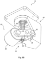
FIG. 8A is a perspective view of an alternative embodiment of a caster with a constant force mechanism. -
FIG. 8B is an alternate perspective view of the caster with a constant force mechanism ofFIG. 8A . -
FIG. 9 is an example of a force profile for two operating regimes (R1, R2) of a caster with a variable constant force mechanism. -
FIG. 10A is a schematic illustration of an embodiment of a position sensor system. -
FIG. 10B is a schematic illustration of an embodiment of a caster with a variable constant force mechanism and including position sensors as part of a position sensor system. -
FIG. 11 is an example of a drive wheel wear profile showing drive wheel wear over time as monitored by a position sensor system. -
FIG. 12 is a plot showing an integration of the wear profile illustrated inFIG. 11 for values of y > yT. -
FIG. 13 is an illustration of a method for operating a position sensor system to send an indication signal. -
FIG. 14 is a rear view of a material handling vehicle equipped with a caster wheel assembly including a variable constant force mechanism according to the present disclosure. -
FIG. 15 is an enlarged partial side view of the material handling vehicle ofFIG. 14 showing the caster wheel assembly including the variable constant force mechanism and an inertial damper. - Several example embodiments of wheel assemblies, including a caster with a constant force mechanism and a caster with a variable constant force mechanism will be described. As one skilled in the art will appreciate, however, the wheel assembly concept may be implemented in a variety of different configurations and arrangements. Moreover, while the example wheel assembly is generally described with reference to a pallet truck, the wheel assembly concept is equally applicable to other types and styles of powered and unpowered vehicles, such as pallet trucks, tow tractors, sideloaders, counterbalanced trucks, reach trucks, wagons, utility trailers, and the like, as non-limiting examples.
- A vehicle in the form of a pallet truck is illustrated in
FIGS. 1-4 . A motorized hand/rider low-lift pallet truck 100 is comprised offork carriage 12 having a pair ofload bearing forks 14 that are coupled to apower unit 11. Thepower unit 11 typically includes a housing that houses a hydraulic lift motor pump and traction motor, adrive wheel 16, and a battery housing that houses a battery. Alternatively, the battery can be mounted directly to thepallet truck 100 without a housing. Thedrive wheel 16 is coupled to asteering mechanism 26 having atiller arm 28 and an operator control handle 30. Thesteering mechanism 26 is rotatable to the right and left to control the steering of thepallet truck 100. - The
fork carriage 12 has a vertical span of several inches, traveling up and down between ground level and the maximum height. Thepallet truck 100 is designed such that theforks 14 are inserted under a load to be moved such as a pallet of goods and thefork carriage 12 lifts the load off of the ground. Thepallet truck 100 may be driven to another location where thefork carriage 12 is lowered to place the load on the ground and theforks 14 are withdrawn from the load. One skilled in the art will appreciate the operation and interconnection of the various components of theexample pallet truck 100. - Regarding the
example pallet truck 100, one ormore wheel assemblies 10 are positioned at the base of thepallet truck 100 and can be positioned near thedrive wheel 16. In one embodiment, thewheel assemblies 10 are casters. Referring toFIG. 5 , thewheel assembly 10 can include features such as asupport 90, awheel 80, and a variableconstant force mechanism 48. In the illustrated embodiment,wheel 80 is coupled to variableconstant force mechanism 48, which is in turn coupled to support 90. Furthermore,support 90 can be pivotally coupled topallet truck 100. In other embodiments illustrated inFIGS. 6-8B , aconstant force mechanism 50 is shown. A secondary spring 68 (discussed below) can be included to provide the "variable" feature to produce the variableconstant force mechanism 48. - The
wheel 80 is illustrated as a caster-type wheel including ahub 82 about which atire 84 is secured. In one form, thehub 82 is metallic (e.g., steel) and thetire 84, which may be non-metallic (e.g., plastic, such as, polyurethane), is molded over or secured to thehub 82. Anaxle 86 extends through from thewheel 80 to couple to arigid arm 70, which is a component of the variableconstant force mechanism 48. Snap rings, clips, or any other restraint may be used to capture theaxle 86, as will be appreciated by one skilled in the art given the benefit of this disclosure. - While the
axle 86 defines a circular cross-section in a plane perpendicular to the longitudinal axis of theaxle 86, many other form factors are available, such as square, hexagonal, triangular, and the like. Furthermore, any number and/or type ofwheels 80 may be supported by theaxle 86; for instance, a pair of solid rubber wheels may be supported by theaxle 86, or one or more plastic wheels may be incorporated. - During operation of the
pallet truck 100, thewheel assemblies 10 can be tuned to provide an appropriate nominal downward force throughout a first operating regime R1 (e.g., 250 lbs inFIG. 9 ). This downward force can be tunable based on desired vehicle performance characteristics. As thedrive wheel 16 wears, the deflection across thewheel 80 will increase but the force applied to thewheel 80 remains fixed at the nominal level. In a second operating regime (R2 inFIG. 9 ) where the deflection across thewheel 80 exceeds a predetermined threshold value (e.g. 0.5 inches inFIG. 9 ), the force applied by thewheel assembly 10 can be increased to accommodate large deflection events such as turning. In a turning event, the deflection can exceed the predetermined value and thewheel assembly 10 can provide the appropriate roll stiffness. WhereasFIG. 9 illustrates a linear increase in force as deflection increases beyond the predetermined threshold, a non-linear force profile may also be used. In one aspect, operating regimes R1 and R2 and corresponding force profiles can vary and may be chosen based onrealistic drive wheel 16 wear rates. Moreover, in some embodiments, only a single operating regime may be implemented, whereas in other embodiments, two, three or more operating regimes may be implemented. - The constant force operating regime can be variable and can be chosen based on
realistic drive wheel 16 wear rates. Realizing the proposed wheel force profile would reduce the frequency of maintenance required to maintain optimal vehicle performance. One way to achieve the desired force profile can be to use a constant force mechanism. Many constant force mechanisms exist in the art and an example of such a mechanism is shown inU.S. Patent No. 7,874,223 . This type of constant force mechanism can be incorporated into awheel assembly 10 as shown inFIG. 5 to resist displacement of thewheel 80 in thewheel assembly 10. The illustrated variableconstant force mechanism 48 includes ahorizontal support 52 and avertical support 54 which can be oriented perpendicular to each other. Thehorizontal support 52 is associated with ahorizontal carriage 56 and a resistance device, such as aspring 64. Similarly, thevertical support 54 is associated with avertical carriage 58 and avertical spring 66. Furthermore, therigid arm 70 can be pivotally coupled to the horizontal 56 and vertical 58 carriages atpoint 60 andpoint 62, respectively. In the illustrated embodiment,point 60 at one end of therigid arm 70 is coupled to thehorizontal carriage 56 andintermediate point 62 located between therigid arm 70 ends is coupled to thevertical carriage 58.Horizontal spring 64 urges thehorizontal carriage 56 horizontally along a horizontal axis defined by thehorizontal support 52 and thevertical spring 66 urges thevertical carriage 58 downwardly along a vertical axis defined by thevertical support 54. Therefore, according to Hooke's law, a force due to thehorizontal spring 64 acting on thehorizontal carriage 56 can be approximated by equation 1:

where FH is the component of horizontal force acting on thehorizontal carriage 56 due to thehorizontal spring 64, xH is the horizontal displacement and k H is the spring rate constant ofspring 64. Similarly, a force on thevertical carriage 58 due to thevertical spring 66 can be approximated by equation 2:

where Fv is the component of vertical force acting on thevertical carriage 58 due to thevertical spring 66, xv is the vertical displacement and k V is the spring rate constant ofspring 66. It can be determined, as previously demonstrated inU.S. Patent No. 7,874,223 , that for the geometry shown inU.S. Patent No. 7,874,223 , when kv and kH are equivalent andhorizontal support 52 andvertical support 54 are orientated perpendicular to each other:

where FR is the resultant force atcarriage 58, and L is the length of the arm betweenpoint 60 andpoint 62 inFIG. 5 . As kv and L are constant, the force FR is therefore constant. When an extension is made to the rigid arm as is the case in the illustrated embodiment, the force at the wheel Fw is

where L is the length of the arm frompoint 60 to point 62 inFIG. 5 and S is the length of the arm from 62 to 86 inFIG. 5 . Here again, because kv, L and S are constant, the force Fw is constant. - The result is that the downward force applied by the caster wheel remains constant throughout the stroke of the variable
constant force mechanism 48. A secondaryvertical spring 68 can be provided on thevertical support 54 coaxial with thevertical spring 66 that applies a greater downward force once the deflection exceeds the predefined constant force region to provide a preferred roll stiffness. - A constant force caster requires less maintenance or a reduced maintenance frequency. Tuning of the caster force profile allows the material handling vehicle equipped with the
wheel configuration 10 to maintain optimal vehicle performance as thedrive wheel 16 wears with reduced maintenance frequency. - Several alternative methods exist for constructing a
wheel support 10 with a constant force mechanism. In lieu of the variable constant force mechanism detailed inFIG. 5 , and the constant force mechanism shown inFIGS. 6-8B , a cam and follower could be used. The cam profile would be shaped to achieve the desired force profile. Likewise, a cam pulley could be used in the same fashion. Other mechanisms are available that create constant forces which are well known in the art. - In addition to the wheel assembly, a material handling vehicle such as
vehicle 100 can be equipped with aposition sensor system 190.FIG. 10A shows a schematic illustration of one embodiment of aposition sensor system 190 which can include one ormore sensors 191, areceiver 192,data storage 193,user interface 194 andindicator 195. In one aspect, each of the components of theposition sensor system 190 can be in communication with each of the other components of theposition sensor system 190. - With reference to
FIG. 10B , the wheel assembly shown inFIG. 5 is illustrated showing possible locations of anexemplary position sensor 191. Theposition sensor 191 can measure a deflection across the caster and output a position or deflection value (seeFIG. 11 ). The deflection provides an indication of the amount of wear (e.g., reduction indrive wheel 16 diameter) that has occurred. In one embodiment, theposition sensor 191 can be a linear encoder and can be used to measure a deflection across the caster wheel (e.g., at a caster-arm pivot point). In some embodiments, the variableconstant force mechanism 48 can perform best within a defined range of deflection. For example, when the measured deflection exceeds a predetermined threshold, asignal 196 can be generated by theposition sensor system 190 to initiate a notice with an indicator 195 (e.g., warning message/indicator, email alert, etc.) advising personnel that the constant force caster wheel assembly measured deflection is exceeding the predetermined threshold. In one aspect, anindicator 195 can provide a notice through auser interface 194. - In some embodiments, the
signal 196 can be communicated wirelessly via a bidirectional warehouse communication system with a computer system at a facility, such as a warehouse or a factory, where the vehicle operates. This enables data regarding the operating parameters to be sent to the computer system and enables thepallet truck 100 to receive data and commands from the computer system. Additionally, the warehouse communication system can be connectable through a network, such as the Intranet, to remote computers, such as at the headquarters of the company that operates the facility and at the manufacturer of the vehicle. -
FIG. 10B illustrates twolinear position sensors Vertical position sensor 191a can detect a vertical displacement of thevertical carriage 58, andhorizontal position sensor 191b can detect a horizontal displacement of thehorizontal carriage 56. In some embodiments,horizontal position sensor 191b (orvertical position sensor 191a) can serve as a back-up tovertical position sensor 191b (orhorizontal position sensor 191b) to provide a redundant position sensor system. Moreover, although two linear position sensors are shown, it is to be understood that asingle position sensor 191 may be included in the design of thewheel assembly 10 without departing from the scope of the invention. If asingle position sensor 191 is provided, thesingle position sensor 191 can measure the displacement of either one of thecarriages carriages - Referring to
FIG. 11 , a plot of an example of a drive wheel wear profile is shown. The drive wheel wear as a function of time is monitored by way of the position sensor, such assensor 191. In the case of a vertical position sensor, the displacement of thevertical carriage 54 can be plotted as a function of time, where y represents that displacement and yT represents a threshold value. InFIG. 11 , an upward displacement (resulting in a compression of the vertical spring) results in an increase of the value of y, whereas a downward displacement (resulting in an extension of the spring) results in a decrease of the value of y. The threshold value yT may be predetermined (e.g., a factory setting) or set by a user. -
FIG. 12 shows a plot of an integration of the wear profile illustrated inFIG. 11 for values of y > yT. In other words, the cumulative area (A) under the curve of the wear profile inFIG. 11 (shaded regions) can be monitored for displacements greater than the threshold displacement value. When the value of A equals or exceeds a threshold value AT, a signal can be generated. The arrow inFIG. 12 indicates the point on the plot at which A = AT. In a manner similar to the selection of yT, AT may also be predetermined (e.g., a factory setting) or set by a user. The signal generated can indicate that the drive wheel may need to be repaired or replaced. Details regarding the signal are described below. - Referring to
FIG. 13 , an embodiment of a process incorporating aposition sensor system 190 is illustrated as amethod 200. Instep 202 of themethod 200, theposition sensor system 190 and theposition sensor 191 can be activated. Activation of theposition sensor system 190 can occur when the vehicle is powered on or can occur intermittently while the vehicle is in operation. In addition, theposition sensor system 190 can be activated manually or automatically. For example, a user can choose to activate theposition sensor system 190 to periodically determine whether a wheel assembly requires maintenance. In some embodiments, theposition sensor system 190 can be reset, for example, following a maintenance procedure. Alternatively, theposition sensor system 190 can be continuously active regardless of the status of the vehicle. - In a
second step 204 of themethod 200, theposition sensor 191 can detect a property of a wheel assembly such aswheel assembly 10. Theposition sensor 191 can be configured to detect the deflection or average deflection of the wheel. In the case where the average deflection is detected, an average deflection value (D) can be recorded. In one example, deflection data can be transmitted from theposition sensor 191 to areceiver 192 that can record the deflection data indata storage 193. In certain embodiments, D can be equivalent to y or A as seen inFIGS. 11-12 . In anext step 206 of themethod 200, D can be compared with a predetermined threshold value (DThreshold). In certain embodiments, DThreshold can be equivalent to yT or AT as seen inFIGS. 11-12 . DThreshold can be chosen to indicate when a signal could be communicated to a user. For example, a user can be notified with anindicator 195 to indicate when the wheel assembly requires maintenance, which can include repairing or replacing the wheel. Based on the degree of wheel wear, DThreshold may be selected to be a value that can be indicative of a level of wheel wear at which maintenance could be considered. Therefore, in astep 206, if D is greater than DThreshold, than in anext step 208 of themethod 200, a signal can be communicated to a user. However, if D is less than or equal to DThreshold, then themethod 200 can return to step 204. - In the case where D exceeds DThreshold, a user can be notified by the
position sensor system 190. The notification can include asignal 196 sent by a wired or wireless communication method to a device such as a computer, cell phone, tablet or other such device oruser interface 194. The notification can also include an audible or visual notification such as an intermittent or constant audible tone or light display provided by anindicator 195. When the notification is received by the user, in astep 210, the user may choose to repair or replace the wheel assembly based on the signal communicated by theposition sensor system 190. - In a further embodiment, a single caster wheel assembly including a constant force mechanism may be used on a material handling vehicle. As a non-limiting example, a caster wheel assembly including a
constant force mechanism 50, or variableconstant force mechanism 48 may be used on a reach truck. In general, a known reach truck may include a caster wheel and inertial damper assembly with coil springs and an inertial damper to dissipate energy. One embodiment of areach truck 101 according to the present technology can include asingle wheel assembly 110, as shown inFIGS. 14 and15 . The coil springs associated with a known caster wheel may be replaced with aconstant force mechanism 50, or variableconstant force mechanism 48 to providewheel assembly 110. In one aspect, thewheel assembly 110 may exert a constant force on a ground surface as thedrive wheel 116 wears. In another aspect,wheel assembly 110 may function similarly towheel assembly 10 as shown, for example, inFIG. 5 . It will be appreciated that embodiments of areach truck 101 or other material handling vehicles may include only onewheel assembly 110 with a constant force mechanism. However, embodiments of areach truck 101 or other material handling vehicles may also include two ormore wheel assemblies 110. In some embodiments, thewheel assembly 110 can also include aninertial damper 220 to help dissipate energy. - Other constant force mechanisms in addition to those described herein and other mechanisms in general may also be used. For example, as an alternative (or in addition) to a caster wheel assembly including a constant force mechanism, a cam and follower may be used. A cam profile may be shaped to achieve a desired force profile. In another aspect, a cam pulley may be used in addition to or in place of a cam and follower.
- While there has been shown and described what is at present considered the preferred embodiments of the invention, it will be appreciated by those skilled in the art that, given the benefit of this invention, various changes and modifications can be made without departing from the scope of the invention defined by the following claims.
Claims (16)
- A wheel assembly (10, 110), comprising:a wheel (16 , 80, 116) having an axle (86); anda constant force mechanism (48, 50) coupled to the wheel (16, 80, 116), characterised by a constant force mechanism (48, 50) comprising:a horizontal support (52);a horizontal carriage (56) associated with the horizontal support (52);a vertical support (54) oriented perpendicular with respect to the horizontal support (52);a vertical carriage (58) associated with the vertical support (54); anda rigid arm (70) that is pivotally coupled with the horizontal carriage (56), the vertical carriage (58), and the axle (86),wherein the rigid arm (70) is coupled with the vertical carriage (58) at a point (62) intermediate where the rigid arm (70) is coupled with the horizontal carriage (56) and the axle (86),wherein a first resistance device (64) is adapted to urge the horizontal carriage (56) along the horizontal support (52), andwherein a second resistance device (66, 68) is adapted to urge the vertical carriage (58) along the vertical support (54).
- The wheel assembly (10, 110) according to claim 1, wherein the first resistance device (64) is a horizontal spring (64), and the second resistance device (66, 68) is a vertical spring (66, 68).
- The wheel assembly (10, 110) according to claim 2, wherein the vertical spring is a first vertical spring (66), and a second vertical spring (68) is disposed coaxial with the first vertical spring (66).
- The wheel assembly (10, 110) according to claim 3, wherein the second vertical spring (68) applies a greater downward force than the first vertical spring (66).
- The wheel assembly (10, 110) according to any one of claims 1 to 4, further comprising a position sensor system (190) that can measure a deflection across the wheel (16, 80, 116).
- The wheel assembly (10, 110) according to claim 5, wherein the position sensor system (190) includes a vertical position sensor (191, 191a) and a horizontal position sensor (191, 191b).
- The wheel assembly (10, 110) according to claims 5 or 6, wherein the position sensor system (190) further includes a user interface (194).
- The wheel assembly (10, 110) according to claims 6 or 7, wherein the vertical position sensor (191, 191a) measures vertical displacement of the vertical carriage (58), and the horizontal position sensor (191, 191b) measures the horizontal displacement of the horizontal carriage (56).
- The wheel assembly (10, 110) according to any one of claims 1 to 8, wherein the vertical carriage (58) is coupled with the rigid arm (70) at a point (62) between ends of the rigid arm (70).
- The wheel assembly (10, 110) according to any one of claims 1 to 9, further comprising a support (90), wherein the support (90) is coupled to the horizontal support (52) and the vertical support (54) of the constant force mechanism (48, 50).
- The wheel assembly (10, 110) according to any one of claims 1 to 10, wherein the wheel (16, 80, 116) is one of a load wheel, a drive wheel, a caster wheel, and a steering wheel.
- The wheel assembly (10, 110) according to any one of claims 2 to 11, wherein a spring constant of the horizontal spring (64) is equivalent to a spring constant of the vertical spring (66, 68).
- A material handling vehicle (100, 101), comprising:a vehicle chassis;a fork carriage (12) coupled to the vehicle chassis;at least one lifting fork (14) coupled to the fork carriage (12) and displaceable in at least one dimension;a drive wheel (16, 116) coupled to the vehicle chassis; andat least one wheel assembly (10, 110) according to claim 1 coupled to the vehicle chassis.
- The wheel assembly (10, 110) according to claim 13, wherein the first resistance device (64) is a horizontal spring (64) and the second resistance device (66, 68) is a vertical spring (66, 68).
- The wheel assembly (10, 110) according to claim 14, wherein the vertical spring is a first vertical spring (66), and a second vertical spring (68) is disposed coaxial with the first vertical spring (66).
- The wheel assembly (10, 110) according to any one of claims 13 to 15, further comprising a position sensor system (190) that can measure a deflection across the wheel (16, 80, 116).
Applications Claiming Priority (2)
| Application Number | Priority Date | Filing Date | Title |
|---|---|---|---|
| US14/242,491 US10315900B2 (en) | 2014-04-01 | 2014-04-01 | Caster wheel with constant force mechanism |
| EP15161975.6A EP2927022B1 (en) | 2014-04-01 | 2015-03-31 | Wheel assembly and method of indicating a maintenance requirement of said wheel assembly |
Related Parent Applications (1)
| Application Number | Title | Priority Date | Filing Date |
|---|---|---|---|
| EP15161975.6A Division EP2927022B1 (en) | 2014-04-01 | 2015-03-31 | Wheel assembly and method of indicating a maintenance requirement of said wheel assembly |
Publications (3)
| Publication Number | Publication Date |
|---|---|
| EP3892476A1 EP3892476A1 (en) | 2021-10-13 |
| EP3892476C0 EP3892476C0 (en) | 2024-01-10 |
| EP3892476B1 true EP3892476B1 (en) | 2024-01-10 |
Family
ID=52814836
Family Applications (2)
| Application Number | Title | Priority Date | Filing Date |
|---|---|---|---|
| EP15161975.6A Active EP2927022B1 (en) | 2014-04-01 | 2015-03-31 | Wheel assembly and method of indicating a maintenance requirement of said wheel assembly |
| EP21172469.5A Active EP3892476B1 (en) | 2014-04-01 | 2015-03-31 | Wheel assembly |
Family Applications Before (1)
| Application Number | Title | Priority Date | Filing Date |
|---|---|---|---|
| EP15161975.6A Active EP2927022B1 (en) | 2014-04-01 | 2015-03-31 | Wheel assembly and method of indicating a maintenance requirement of said wheel assembly |
Country Status (5)
| Country | Link |
|---|---|
| US (2) | US10315900B2 (en) |
| EP (2) | EP2927022B1 (en) |
| CN (2) | CN110802986B (en) |
| AU (2) | AU2015201587B2 (en) |
| CA (2) | CA2886593C (en) |
Families Citing this family (17)
| Publication number | Priority date | Publication date | Assignee | Title |
|---|---|---|---|---|
| US10315900B2 (en) | 2014-04-01 | 2019-06-11 | The Raymond Corporation | Caster wheel with constant force mechanism |
| US9593003B2 (en) * | 2014-04-01 | 2017-03-14 | The Raymond Corporation | Caster wheel with constant force mechanism |
| DE102015009816B4 (en) * | 2015-07-28 | 2019-01-03 | MAQUET GmbH | Motorized storage area transporter, operating table system with storage area transporter and roller drive for a rack |
| DE102016104746A1 (en) * | 2016-03-15 | 2017-09-21 | Linde Material Handling Gmbh | Support roller of a truck |
| AU2017208328A1 (en) * | 2016-08-03 | 2018-02-22 | The Raymond Corporation | Caster wheels with torsion spring assembly |
| CN107784799B (en) * | 2016-08-26 | 2019-07-19 | 北京协同创新智能电网技术有限公司 | A multivariable alarm method and system based on online change direction |
| US10118440B1 (en) * | 2017-06-12 | 2018-11-06 | Colson Caster Group, Llc | Suspension caster with brake lever and wheel fork and yoke portion having common pivot axis |
| US10518578B1 (en) * | 2018-11-26 | 2019-12-31 | Hamilton Caster & Manufacturing Company | Dual-stage spring loaded caster |
| CN109532007B (en) * | 2018-12-28 | 2024-03-08 | 苏州慧通汇创科技有限公司 | DLP laser rapid prototyping 3D printer positioning system that precision is high |
| CN111039230A (en) * | 2019-12-30 | 2020-04-21 | 视航机器人(佛山)有限公司 | Mileage measuring device and unmanned forklift |
| CN111361659B (en) * | 2020-03-06 | 2021-08-24 | 中国南方电网有限责任公司超高压输电公司广州局 | Wheel-leg obstacle crossing mechanism and obstacle crossing robot |
| CN111792580A (en) * | 2020-08-14 | 2020-10-20 | 杭州海康机器人技术有限公司 | A forklift outrigger and automatic guided forklift |
| CN112026956B (en) * | 2020-08-28 | 2021-12-31 | 广东博智林机器人有限公司 | Suspension structure, mobile chassis and mobile building equipment |
| CN112279155B (en) * | 2020-10-20 | 2022-07-19 | 苏州三鼎升降机有限公司 | Hydraulic lift truck for carrying armored movable switch cabinet function vehicle |
| CN112413049A (en) * | 2020-11-03 | 2021-02-26 | 珠海格力电器股份有限公司 | Can install shock attenuation module and mobile device of runner |
| USD1050664S1 (en) * | 2021-02-16 | 2024-11-05 | Tata Consultancy Services Limited | Apparatus for handling goods |
| WO2024215211A1 (en) * | 2023-04-14 | 2024-10-17 | Howard Wright Limited | A wheel assembly for a wheeled apparatus |
Family Cites Families (106)
| Publication number | Priority date | Publication date | Assignee | Title |
|---|---|---|---|---|
| US1242500A (en) * | 1916-05-25 | 1917-10-09 | Newton K Wilcox | Tractor. |
| US1906238A (en) | 1932-06-02 | 1933-05-02 | Faultless Caster Co | Top bearing adjustable and cushion frame for casters |
| US2339940A (en) * | 1941-12-02 | 1944-01-25 | Bond Foundry & Machine Company | Movable truck jack |
| US2443480A (en) * | 1943-12-11 | 1948-06-15 | Schwitzer Cummins Company | Power-driven vehicle |
| US2438571A (en) * | 1944-05-27 | 1948-03-30 | Jr Glenway Maxon | Stabilizer for spring mounted vehicles |
| US2606021A (en) | 1945-09-21 | 1952-08-05 | Chrysler Corp | Suspension |
| US2455787A (en) | 1945-09-24 | 1948-12-07 | Frank F Linn Corp | Trailer axle |
| US2426513A (en) | 1947-02-25 | 1947-08-26 | Linn Company | Wheel suspension for vehicles |
| US2580557A (en) | 1947-09-02 | 1952-01-01 | Kolbe Joachim | Vehicle with independent wheel suspension |
| US2709829A (en) | 1954-03-26 | 1955-06-07 | Marvin Landplane Company | Stabilized caster |
| US2831699A (en) * | 1954-05-03 | 1958-04-22 | Superior Engineering Corp | Truck wheel assembly |
| US2891764A (en) | 1956-07-13 | 1959-06-23 | Frank S Pearne | Jack structure supported by spring mounted wheels |
| US3331618A (en) | 1965-12-09 | 1967-07-18 | Elden N Head | Coil torsion spring trailer hitch |
| US3380546A (en) * | 1966-02-14 | 1968-04-30 | Rodney R. Rabjohn | Traction drive for small vehicles |
| US3764157A (en) | 1972-01-12 | 1973-10-09 | Blanc E Le | Rough terrain pack vehicle |
| US4000912A (en) | 1975-02-21 | 1977-01-04 | Mse Corporation | Shock absorber |
| US4371191A (en) * | 1977-08-22 | 1983-02-01 | Springhill Laboratories, Inc. | Adjusting automobile suspension system |
| US4263979A (en) * | 1978-11-09 | 1981-04-28 | Rpc Corporation | Hydraulic master-slave steering system for a wide track vehicle |
| US4246567A (en) | 1979-07-23 | 1981-01-20 | Facet Enterprises, Inc. | Device for detecting and indicating low pressure and high heat in pneumatic tires |
| US4449725A (en) | 1981-05-08 | 1984-05-22 | Robison William G | Support for booms and other field equipment |
| FR2544259A1 (en) | 1983-04-12 | 1984-10-19 | Renault | Rear suspension with independent wheels for a motor vehicle |
| US4534433A (en) | 1983-09-19 | 1985-08-13 | The Raymond Corporation | Material handling vehicle |
| JPS6093504U (en) | 1983-12-01 | 1985-06-26 | アップリカ葛西株式会社 | caster |
| DE3402495A1 (en) * | 1984-01-25 | 1985-07-25 | Steinbock Gmbh, 8052 Moosburg | LOCKED STEERING CONVEYOR |
| SE449482B (en) * | 1985-07-08 | 1987-05-04 | Bygg Och Transportekonomie Ab | DEVICE FOR OPENING THE BRAKE FORM OF INDUSTRIAL TRUCKS |
| GB8605540D0 (en) * | 1986-03-06 | 1986-04-09 | Lucas Ind Plc | Vehicle |
| US4862113A (en) | 1988-01-06 | 1989-08-29 | International Business Machines Corporation | Sinusoidal oscillator with instant start-up |
| JPH0629148Y2 (en) * | 1988-03-20 | 1994-08-10 | 杉安工業株式会社 | Transfer device for container with casters |
| US5072960A (en) | 1990-02-15 | 1991-12-17 | Sterilizer Technologies Corporation | Sterilizer cart |
| US5099708A (en) * | 1991-05-10 | 1992-03-31 | Chung Ming Chin | Adjustable rolling cam slider |
| US5163701A (en) | 1991-09-09 | 1992-11-17 | Csn Manufacturing, Inc. | Torsion spring vehicle suspension |
| US5326128A (en) | 1991-09-09 | 1994-07-05 | Csn Manufacturing, Inc. | Variable-width torsion spring axle |
| DE4205150C2 (en) | 1992-02-20 | 1995-03-09 | Jungheinrich Ag | Swivel castor for industrial trucks |
| DE4209862A1 (en) | 1992-03-26 | 1993-09-30 | Linde Ag | Pallet truck |
| GB2273865A (en) * | 1992-12-19 | 1994-07-06 | Fedag | A vacuum cleaner with an electrically driven brush roller |
| US5579859A (en) * | 1995-02-10 | 1996-12-03 | Crown Equipment Corporation | Isolated floor for material handling vehicle |
| US5685555A (en) * | 1995-02-21 | 1997-11-11 | The Raymond Corporation | Lift truck with inertial damper |
| US5649454A (en) | 1995-05-15 | 1997-07-22 | Purdue Research Foundation | Compliant constant-force mechanism and devices formed therewith |
| US5628377A (en) * | 1995-06-16 | 1997-05-13 | M I C, Societe Anonyme | Goods-handling cart with stabilizing wheels |
| US6244025B1 (en) * | 1996-07-27 | 2001-06-12 | Ferris Industries, Inc. | Load compensation adjustment in lawnmower having independent suspension |
| US7107746B2 (en) * | 1996-07-27 | 2006-09-19 | Ferris, A Division Of Simplicity Manufacturing, Inc. | Mower suspension system and method |
| DE19753412C2 (en) * | 1997-12-02 | 2001-03-22 | Jungheinrich Ag | Pallet truck with adjustable support roller |
| JPH11180104A (en) | 1997-12-24 | 1999-07-06 | Otsuka Chem Co Ltd | Caster |
| JP3134849B2 (en) * | 1998-07-31 | 2001-02-13 | コクヨ株式会社 | Simple stage |
| JP3691262B2 (en) | 1998-11-09 | 2005-09-07 | 日産ディーゼル工業株式会社 | Suspension device |
| US6135485A (en) | 1998-11-11 | 2000-10-24 | Illinois Tool Works Inc. | Pivotal towbar torsional spring |
| IT1308979B1 (en) | 1999-01-20 | 2002-01-15 | Montini & C S N C | CUSHIONED AND VARIABLE STRING SUSPENSION, PARTICULARLY FOR THE REAR AND STEERING WHEELS OF A THREE-WHEEL FORKLIFT TRUCK. |
| KR100383370B1 (en) * | 1999-02-08 | 2003-05-12 | 카야바 고교 가부시기가이샤 | Caster |
| US6357077B1 (en) | 1999-10-15 | 2002-03-19 | Hamilton Caster & Mfg. Co. | Spring loaded caster |
| US6543798B2 (en) | 2000-04-04 | 2003-04-08 | Pride Mobility Products Corporation | Anti-tip caster suspension for a wheelchair |
| DE10022400C5 (en) | 2000-04-20 | 2008-11-06 | Jungheinrich Ag | Pallet truck with a five-wheel drive |
| US6484359B1 (en) | 2000-06-14 | 2002-11-26 | Algood Casters Limited | Load indicating spring caster |
| JP4013468B2 (en) * | 2000-09-11 | 2007-11-28 | 株式会社豊田自動織機 | Industrial vehicle suspension system |
| DE10105300A1 (en) * | 2001-02-02 | 2002-08-08 | Continental Teves Ag & Co Ohg | Suspension in form of steel spring has mechanical lever transmission to alter mechanical transmission ratio of wheel travel in suspension |
| US7070028B2 (en) * | 2001-02-07 | 2006-07-04 | Tenneco Automotive Operating Company Inc. | Frequency dependent damper |
| US6759952B2 (en) | 2001-07-06 | 2004-07-06 | Trw Inc. | Tire and suspension warning and monitoring system |
| US6550101B2 (en) * | 2001-07-30 | 2003-04-22 | Ross Design & Engineering, Inc. | Hydraulic constant force caster |
| JP2003079671A (en) | 2001-09-12 | 2003-03-18 | 紘二 ▲吉▼岡 | Front wheel support mechanism for wheelchair |
| US6604414B1 (en) | 2001-12-04 | 2003-08-12 | Dana Corporation | Supply and tire pressure sensing apparatus and method |
| GB2385044B (en) | 2002-02-12 | 2005-03-09 | Nippon Yusoki Co Ltd | Reach type forklift truck |
| US7093319B2 (en) * | 2002-06-28 | 2006-08-22 | Superior Tire & Rubber Corporation | Industrial caster wheel with elastomeric spring/damper member and adjustment member |
| AU2003279045A1 (en) * | 2002-10-02 | 2004-04-23 | Harlan Silverstein | Pneumatic locking swivel caster |
| WO2004096905A2 (en) * | 2003-04-24 | 2004-11-11 | Arizona Board Of Regents, Acting For And On Behalf Of Arizona State University | Adjustable compliant mechanism |
| NL1023789C2 (en) * | 2003-07-01 | 2005-01-04 | Bugaboo Design And Sales B V | Pram with spring wheel, spring wheel and swivel castor. |
| DE102004002188A1 (en) * | 2004-01-16 | 2005-08-11 | Jungheinrich Ag | Truck with traction drive and ride-along |
| DE102004019072A1 (en) | 2004-04-20 | 2005-11-17 | Om Carrelli Elevatori S.P.A. | Industrial truck, in particular pallet truck |
| JP2005350154A (en) * | 2004-06-08 | 2005-12-22 | Mitsubishi Heavy Ind Ltd | Forklift |
| US7334642B2 (en) * | 2004-07-15 | 2008-02-26 | Schlumberger Technology Corporation | Constant force actuator |
| US7267349B2 (en) | 2004-09-03 | 2007-09-11 | Beech Engineering & Manufacturing | Material handling lift vehicle and suspension system for use therewith |
| US20060090885A1 (en) | 2004-10-29 | 2006-05-04 | Stephen Montgomery | Thermally conductive channel between a semiconductor chip and an external thermal interface |
| JP4884394B2 (en) * | 2004-12-01 | 2012-02-29 | ボリンジア インダストリー アーゲー | A type of traveling object that is designed to be manipulated by a walking person |
| JP2008523360A (en) | 2004-12-06 | 2008-07-03 | エヌエックスピー ビー ヴィ | System, data carrier, reader and method for measuring wheel peripheral speed and distance traveled |
| JP4546308B2 (en) * | 2005-03-30 | 2010-09-15 | 本田技研工業株式会社 | Control device for variable damping force damper |
| CH698063B1 (en) * | 2005-03-31 | 2009-05-15 | Degonda Rehab Sa | Steering unit and wheelchair with at least one steering wheel unit. |
| US7770904B2 (en) * | 2005-04-14 | 2010-08-10 | Nmhg Oregon, Llc | Stability system for an industrial vehicle |
| EP2172359B1 (en) * | 2005-09-20 | 2012-12-19 | Atlet AB | Improved control system for an industrial truck |
| KR20060082068A (en) | 2006-06-20 | 2006-07-14 | 정만희 | Buffer using the lever principle |
| CN101610968B (en) * | 2007-01-08 | 2013-05-08 | 比沙门工业股份有限公司 | Lift for skids and pallets |
| ITMI20071103A1 (en) | 2007-05-30 | 2008-11-30 | Campagnolo Srl | RIM FOR BICYCLE WHEEL IN COMPOSITE MATERIAL WITH WEAR INDICATOR AND WHEEL INCLUDING SUCH RIM |
| US8235161B2 (en) * | 2007-07-06 | 2012-08-07 | Nmhg Oregon, Llc | Multiple-position steering control device |
| US7861820B1 (en) * | 2007-07-26 | 2011-01-04 | Nmhg Oregon, Llc | Electronically steered and sprung idler assembly |
| WO2009031087A1 (en) * | 2007-09-03 | 2009-03-12 | Philips Intellectual Property & Standards Gmbh | Laser sensor based system for status detection of tires |
| US7762129B2 (en) | 2007-09-25 | 2010-07-27 | Infineon Technologies Ag | Tire tread detection and measurement of physical variables of a tire on a moving vehicle |
| US7896358B2 (en) * | 2007-10-25 | 2011-03-01 | The Raymond Corporation | Magneto-rheological inertial damping system for lift trucks |
| JP2010089615A (en) | 2008-10-07 | 2010-04-22 | Toyota Motor Corp | Suspension device for vehicle |
| JP5421031B2 (en) * | 2009-08-28 | 2014-02-19 | ユニキャリア株式会社 | Heavy goods cart |
| US20120049610A1 (en) | 2010-08-30 | 2012-03-01 | Reynolds Cycling Llc | Rim Wear Indicator |
| CN103328235B (en) * | 2010-12-13 | 2016-06-29 | 瑞典高级汽车商行有限公司 | Wheel suspension and motor vehicles |
| CN201962028U (en) * | 2010-12-27 | 2011-09-07 | 上海梯佑国际贸易有限公司 | Novel manual jack-up type tray fork truck |
| JP6076260B2 (en) * | 2010-12-30 | 2017-02-08 | コンパニー ゼネラール デ エタブリッスマン ミシュラン | Piezoelectric based system and method for determining tire load |
| US8731785B2 (en) * | 2011-03-18 | 2014-05-20 | The Raymond Corporation | Dynamic stability control systems and methods for industrial lift trucks |
| US9403667B2 (en) * | 2011-03-18 | 2016-08-02 | The Raymond Corporation | Dynamic vibration control systems and methods for industrial lift trucks |
| EP2889156B1 (en) * | 2011-03-23 | 2019-09-04 | Breville Pty Limited | Improved wheel assembly |
| WO2012153170A1 (en) * | 2011-05-11 | 2012-11-15 | Softwheel Ltd. | Selective wheel suspension system |
| US8733770B2 (en) * | 2011-12-19 | 2014-05-27 | Agco Corporation | Steerable rear axle system for dual-path steered windrower tractor |
| US8763990B2 (en) * | 2012-03-20 | 2014-07-01 | The Raymond Corporation | Turn stability systems and methods for lift trucks |
| CN102765296A (en) * | 2012-07-25 | 2012-11-07 | 广州风神物流有限公司 | Novel industrial shock absorption caster wheel |
| US9302893B2 (en) * | 2013-02-07 | 2016-04-05 | The Raymond Corporation | Vibration control systems and methods for industrial lift trucks |
| US9002557B2 (en) * | 2013-03-14 | 2015-04-07 | The Raymond Corporation | Systems and methods for maintaining an industrial lift truck within defined bounds |
| US9168784B2 (en) | 2013-03-15 | 2015-10-27 | Cnh Industrial America Llc | Self-propelled windrower tailwheel non-zero caster for stability |
| US9809078B2 (en) * | 2013-03-15 | 2017-11-07 | ClearMotion, Inc. | Multi-path fluid diverter valve |
| CN203185988U (en) * | 2013-04-19 | 2013-09-11 | 胡坚兴 | Shock absorption trundle |
| US9085203B2 (en) * | 2013-07-29 | 2015-07-21 | Deere & Company | Tire load sensing system |
| US10315900B2 (en) | 2014-04-01 | 2019-06-11 | The Raymond Corporation | Caster wheel with constant force mechanism |
| US9533863B2 (en) * | 2014-10-23 | 2017-01-03 | Jungheinrich Aktiengesellschaft | Industrial truck |
| US9956822B1 (en) * | 2016-12-22 | 2018-05-01 | Olympia International, Inc. | Wheel assembly for luggage |
-
2014
- 2014-04-01 US US14/242,491 patent/US10315900B2/en active Active
-
2015
- 2015-03-27 AU AU2015201587A patent/AU2015201587B2/en active Active
- 2015-03-31 EP EP15161975.6A patent/EP2927022B1/en active Active
- 2015-03-31 EP EP21172469.5A patent/EP3892476B1/en active Active
- 2015-03-31 CA CA2886593A patent/CA2886593C/en active Active
- 2015-03-31 CA CA3162794A patent/CA3162794C/en active Active
- 2015-04-01 CN CN201911250097.0A patent/CN110802986B/en active Active
- 2015-04-01 CN CN201510271776.1A patent/CN105291738B/en active Active
-
2019
- 2019-04-17 AU AU2019202681A patent/AU2019202681B2/en active Active
- 2019-05-24 US US16/421,933 patent/US11186469B2/en active Active
Also Published As
| Publication number | Publication date |
|---|---|
| EP3892476A1 (en) | 2021-10-13 |
| CA3162794A1 (en) | 2015-10-01 |
| CN105291738A (en) | 2016-02-03 |
| EP2927022A1 (en) | 2015-10-07 |
| CN105291738B (en) | 2019-12-31 |
| CN110802986B (en) | 2023-07-07 |
| CA2886593A1 (en) | 2015-10-01 |
| US10315900B2 (en) | 2019-06-11 |
| AU2015201587B2 (en) | 2019-01-17 |
| US11186469B2 (en) | 2021-11-30 |
| HK1215419A1 (en) | 2016-08-26 |
| EP2927022B1 (en) | 2021-06-02 |
| AU2019202681B2 (en) | 2021-01-07 |
| US20150274495A1 (en) | 2015-10-01 |
| CA2886593C (en) | 2023-05-23 |
| CN110802986A (en) | 2020-02-18 |
| US20190276289A1 (en) | 2019-09-12 |
| EP3892476C0 (en) | 2024-01-10 |
| CA3162794C (en) | 2024-01-09 |
| AU2015201587A1 (en) | 2015-10-15 |
| AU2019202681A1 (en) | 2019-05-09 |
Similar Documents
| Publication | Publication Date | Title |
|---|---|---|
| AU2019202681B2 (en) | Caster wheel with constant force mechanism | |
| US20160340162A1 (en) | Caster wheels with torsion spring assembly | |
| US9593003B2 (en) | Caster wheel with constant force mechanism | |
| CA3067239C (en) | Trailer stabilizer and leveler | |
| US8641062B2 (en) | Lift axle suspension systems incorporating compression coil springs | |
| EP3279009A1 (en) | Caster wheels with torsion spring assembly | |
| WO2006059200B1 (en) | A wheeled object of the type adapted to be operated by a walking person | |
| KR20200013544A (en) | Fork lift | |
| KR20190080183A (en) | Axial load sensor module with axle load | |
| WO2013059243A1 (en) | Maximizing scissor lift breakover angle with fixed pothole protection | |
| CN103434982B (en) | Tray truck with aiding support wheel apparatus | |
| CN110719887A (en) | Device for moving a load and lifting member therefor | |
| HK1215419B (en) | Wheel assembly and method of indicating a maintenance requirement of said wheel assembly | |
| HK40024656A (en) | Wheel assembly with constant force mechanism | |
| HK40024656B (en) | Wheel assembly with constant force mechanism | |
| DE102013109828B4 (en) | industrial truck | |
| US20250320098A1 (en) | Mast hydraulic sensing system and method | |
| JP2019094184A (en) | Floor surface structure of pit and vehicular lift device used therein |
Legal Events
| Date | Code | Title | Description |
|---|---|---|---|
| PUAI | Public reference made under article 153(3) epc to a published international application that has entered the european phase |
Free format text: ORIGINAL CODE: 0009012 |
|
| STAA | Information on the status of an ep patent application or granted ep patent |
Free format text: STATUS: THE APPLICATION HAS BEEN PUBLISHED |
|
| AC | Divisional application: reference to earlier application |
Ref document number: 2927022 Country of ref document: EP Kind code of ref document: P |
|
| AK | Designated contracting states |
Kind code of ref document: A1 Designated state(s): AL AT BE BG CH CY CZ DE DK EE ES FI FR GB GR HR HU IE IS IT LI LT LU LV MC MK MT NL NO PL PT RO RS SE SI SK SM TR |
|
| STAA | Information on the status of an ep patent application or granted ep patent |
Free format text: STATUS: REQUEST FOR EXAMINATION WAS MADE |
|
| 17P | Request for examination filed |
Effective date: 20220224 |
|
| RBV | Designated contracting states (corrected) |
Designated state(s): AL AT BE BG CH CY CZ DE DK EE ES FI FR GB GR HR HU IE IS IT LI LT LU LV MC MK MT NL NO PL PT RO RS SE SI SK SM TR |
|
| GRAP | Despatch of communication of intention to grant a patent |
Free format text: ORIGINAL CODE: EPIDOSNIGR1 |
|
| STAA | Information on the status of an ep patent application or granted ep patent |
Free format text: STATUS: GRANT OF PATENT IS INTENDED |
|
| RIC1 | Information provided on ipc code assigned before grant |
Ipc: B60G 17/00 20060101ALI20230623BHEP Ipc: B66F 9/075 20060101ALI20230623BHEP Ipc: B60B 33/04 20060101AFI20230623BHEP |
|
| INTG | Intention to grant announced |
Effective date: 20230724 |
|
| GRAS | Grant fee paid |
Free format text: ORIGINAL CODE: EPIDOSNIGR3 |
|
| GRAA | (expected) grant |
Free format text: ORIGINAL CODE: 0009210 |
|
| STAA | Information on the status of an ep patent application or granted ep patent |
Free format text: STATUS: THE PATENT HAS BEEN GRANTED |
|
| AC | Divisional application: reference to earlier application |
Ref document number: 2927022 Country of ref document: EP Kind code of ref document: P |
|
| AK | Designated contracting states |
Kind code of ref document: B1 Designated state(s): AL AT BE BG CH CY CZ DE DK EE ES FI FR GB GR HR HU IE IS IT LI LT LU LV MC MK MT NL NO PL PT RO RS SE SI SK SM TR |
|
| REG | Reference to a national code |
Ref country code: GB Ref legal event code: FG4D |
|
| REG | Reference to a national code |
Ref country code: CH Ref legal event code: EP |
|
| REG | Reference to a national code |
Ref country code: DE Ref legal event code: R096 Ref document number: 602015087281 Country of ref document: DE |
|
| REG | Reference to a national code |
Ref country code: IE Ref legal event code: FG4D |
|
| U01 | Request for unitary effect filed |
Effective date: 20240123 |
|
| U07 | Unitary effect registered |
Designated state(s): AT BE BG DE DK EE FI FR IT LT LU LV MT NL PT SE SI Effective date: 20240131 |
|
| U20 | Renewal fee for the european patent with unitary effect paid |
Year of fee payment: 10 Effective date: 20240207 |
|
| PG25 | Lapsed in a contracting state [announced via postgrant information from national office to epo] |
Ref country code: IS Free format text: LAPSE BECAUSE OF FAILURE TO SUBMIT A TRANSLATION OF THE DESCRIPTION OR TO PAY THE FEE WITHIN THE PRESCRIBED TIME-LIMIT Effective date: 20240510 |
|
| PG25 | Lapsed in a contracting state [announced via postgrant information from national office to epo] |
Ref country code: GR Free format text: LAPSE BECAUSE OF FAILURE TO SUBMIT A TRANSLATION OF THE DESCRIPTION OR TO PAY THE FEE WITHIN THE PRESCRIBED TIME-LIMIT Effective date: 20240411 |
|
| PG25 | Lapsed in a contracting state [announced via postgrant information from national office to epo] |
Ref country code: RS Free format text: LAPSE BECAUSE OF FAILURE TO SUBMIT A TRANSLATION OF THE DESCRIPTION OR TO PAY THE FEE WITHIN THE PRESCRIBED TIME-LIMIT Effective date: 20240410 Ref country code: HR Free format text: LAPSE BECAUSE OF FAILURE TO SUBMIT A TRANSLATION OF THE DESCRIPTION OR TO PAY THE FEE WITHIN THE PRESCRIBED TIME-LIMIT Effective date: 20240110 |
|
| PG25 | Lapsed in a contracting state [announced via postgrant information from national office to epo] |
Ref country code: ES Free format text: LAPSE BECAUSE OF FAILURE TO SUBMIT A TRANSLATION OF THE DESCRIPTION OR TO PAY THE FEE WITHIN THE PRESCRIBED TIME-LIMIT Effective date: 20240110 |
|
| PG25 | Lapsed in a contracting state [announced via postgrant information from national office to epo] |
Ref country code: RS Free format text: LAPSE BECAUSE OF FAILURE TO SUBMIT A TRANSLATION OF THE DESCRIPTION OR TO PAY THE FEE WITHIN THE PRESCRIBED TIME-LIMIT Effective date: 20240410 Ref country code: NO Free format text: LAPSE BECAUSE OF FAILURE TO SUBMIT A TRANSLATION OF THE DESCRIPTION OR TO PAY THE FEE WITHIN THE PRESCRIBED TIME-LIMIT Effective date: 20240410 Ref country code: IS Free format text: LAPSE BECAUSE OF FAILURE TO SUBMIT A TRANSLATION OF THE DESCRIPTION OR TO PAY THE FEE WITHIN THE PRESCRIBED TIME-LIMIT Effective date: 20240510 Ref country code: HR Free format text: LAPSE BECAUSE OF FAILURE TO SUBMIT A TRANSLATION OF THE DESCRIPTION OR TO PAY THE FEE WITHIN THE PRESCRIBED TIME-LIMIT Effective date: 20240110 Ref country code: GR Free format text: LAPSE BECAUSE OF FAILURE TO SUBMIT A TRANSLATION OF THE DESCRIPTION OR TO PAY THE FEE WITHIN THE PRESCRIBED TIME-LIMIT Effective date: 20240411 Ref country code: ES Free format text: LAPSE BECAUSE OF FAILURE TO SUBMIT A TRANSLATION OF THE DESCRIPTION OR TO PAY THE FEE WITHIN THE PRESCRIBED TIME-LIMIT Effective date: 20240110 |
|
| PG25 | Lapsed in a contracting state [announced via postgrant information from national office to epo] |
Ref country code: PL Free format text: LAPSE BECAUSE OF FAILURE TO SUBMIT A TRANSLATION OF THE DESCRIPTION OR TO PAY THE FEE WITHIN THE PRESCRIBED TIME-LIMIT Effective date: 20240110 |
|
| PG25 | Lapsed in a contracting state [announced via postgrant information from national office to epo] |
Ref country code: PL Free format text: LAPSE BECAUSE OF FAILURE TO SUBMIT A TRANSLATION OF THE DESCRIPTION OR TO PAY THE FEE WITHIN THE PRESCRIBED TIME-LIMIT Effective date: 20240110 |
|
| REG | Reference to a national code |
Ref country code: DE Ref legal event code: R097 Ref document number: 602015087281 Country of ref document: DE |
|
| PG25 | Lapsed in a contracting state [announced via postgrant information from national office to epo] |
Ref country code: SM Free format text: LAPSE BECAUSE OF FAILURE TO SUBMIT A TRANSLATION OF THE DESCRIPTION OR TO PAY THE FEE WITHIN THE PRESCRIBED TIME-LIMIT Effective date: 20240110 |
|
| PG25 | Lapsed in a contracting state [announced via postgrant information from national office to epo] |
Ref country code: CZ Free format text: LAPSE BECAUSE OF FAILURE TO SUBMIT A TRANSLATION OF THE DESCRIPTION OR TO PAY THE FEE WITHIN THE PRESCRIBED TIME-LIMIT Effective date: 20240110 |
|
| PG25 | Lapsed in a contracting state [announced via postgrant information from national office to epo] |
Ref country code: SK Free format text: LAPSE BECAUSE OF FAILURE TO SUBMIT A TRANSLATION OF THE DESCRIPTION OR TO PAY THE FEE WITHIN THE PRESCRIBED TIME-LIMIT Effective date: 20240110 |
|
| PG25 | Lapsed in a contracting state [announced via postgrant information from national office to epo] |
Ref country code: SM Free format text: LAPSE BECAUSE OF FAILURE TO SUBMIT A TRANSLATION OF THE DESCRIPTION OR TO PAY THE FEE WITHIN THE PRESCRIBED TIME-LIMIT Effective date: 20240110 Ref country code: SK Free format text: LAPSE BECAUSE OF FAILURE TO SUBMIT A TRANSLATION OF THE DESCRIPTION OR TO PAY THE FEE WITHIN THE PRESCRIBED TIME-LIMIT Effective date: 20240110 Ref country code: RO Free format text: LAPSE BECAUSE OF FAILURE TO SUBMIT A TRANSLATION OF THE DESCRIPTION OR TO PAY THE FEE WITHIN THE PRESCRIBED TIME-LIMIT Effective date: 20240110 Ref country code: CZ Free format text: LAPSE BECAUSE OF FAILURE TO SUBMIT A TRANSLATION OF THE DESCRIPTION OR TO PAY THE FEE WITHIN THE PRESCRIBED TIME-LIMIT Effective date: 20240110 |
|
| REG | Reference to a national code |
Ref country code: CH Ref legal event code: PL |
|
| PLBE | No opposition filed within time limit |
Free format text: ORIGINAL CODE: 0009261 |
|
| STAA | Information on the status of an ep patent application or granted ep patent |
Free format text: STATUS: NO OPPOSITION FILED WITHIN TIME LIMIT |
|
| PG25 | Lapsed in a contracting state [announced via postgrant information from national office to epo] |
Ref country code: MC Free format text: LAPSE BECAUSE OF FAILURE TO SUBMIT A TRANSLATION OF THE DESCRIPTION OR TO PAY THE FEE WITHIN THE PRESCRIBED TIME-LIMIT Effective date: 20240110 |
|
| PG25 | Lapsed in a contracting state [announced via postgrant information from national office to epo] |
Ref country code: MC Free format text: LAPSE BECAUSE OF FAILURE TO SUBMIT A TRANSLATION OF THE DESCRIPTION OR TO PAY THE FEE WITHIN THE PRESCRIBED TIME-LIMIT Effective date: 20240110 |
|
| 26N | No opposition filed |
Effective date: 20241011 |
|
| PG25 | Lapsed in a contracting state [announced via postgrant information from national office to epo] |
Ref country code: IE Free format text: LAPSE BECAUSE OF NON-PAYMENT OF DUE FEES Effective date: 20240331 |
|
| PG25 | Lapsed in a contracting state [announced via postgrant information from national office to epo] |
Ref country code: IE Free format text: LAPSE BECAUSE OF NON-PAYMENT OF DUE FEES Effective date: 20240331 Ref country code: CH Free format text: LAPSE BECAUSE OF NON-PAYMENT OF DUE FEES Effective date: 20240331 |
|
| U20 | Renewal fee for the european patent with unitary effect paid |
Year of fee payment: 11 Effective date: 20250205 |
|
| PG25 | Lapsed in a contracting state [announced via postgrant information from national office to epo] |
Ref country code: CY Free format text: LAPSE BECAUSE OF FAILURE TO SUBMIT A TRANSLATION OF THE DESCRIPTION OR TO PAY THE FEE WITHIN THE PRESCRIBED TIME-LIMIT; INVALID AB INITIO Effective date: 20150331 |
|
| PG25 | Lapsed in a contracting state [announced via postgrant information from national office to epo] |
Ref country code: HU Free format text: LAPSE BECAUSE OF FAILURE TO SUBMIT A TRANSLATION OF THE DESCRIPTION OR TO PAY THE FEE WITHIN THE PRESCRIBED TIME-LIMIT; INVALID AB INITIO Effective date: 20150331 |
|
| PG25 | Lapsed in a contracting state [announced via postgrant information from national office to epo] |
Ref country code: TR Free format text: LAPSE BECAUSE OF FAILURE TO SUBMIT A TRANSLATION OF THE DESCRIPTION OR TO PAY THE FEE WITHIN THE PRESCRIBED TIME-LIMIT Effective date: 20240110 |
|
| U20 | Renewal fee for the european patent with unitary effect paid |
Year of fee payment: 12 Effective date: 20260209 |
|
| PGFP | Annual fee paid to national office [announced via postgrant information from national office to epo] |
Ref country code: GB Payment date: 20260209 Year of fee payment: 12 |