EP3892449A1 - Method for forming a three dimensional body from a mixture with a high content of solid particles - Google Patents
Method for forming a three dimensional body from a mixture with a high content of solid particles Download PDFInfo
- Publication number
- EP3892449A1 EP3892449A1 EP21169287.6A EP21169287A EP3892449A1 EP 3892449 A1 EP3892449 A1 EP 3892449A1 EP 21169287 A EP21169287 A EP 21169287A EP 3892449 A1 EP3892449 A1 EP 3892449A1
- Authority
- EP
- European Patent Office
- Prior art keywords
- mixture
- forming
- solid particles
- particles
- dimensional body
- Prior art date
- Legal status (The legal status is an assumption and is not a legal conclusion. Google has not performed a legal analysis and makes no representation as to the accuracy of the status listed.)
- Granted
Links
Images









Classifications
-
- B—PERFORMING OPERATIONS; TRANSPORTING
- B29—WORKING OF PLASTICS; WORKING OF SUBSTANCES IN A PLASTIC STATE IN GENERAL
- B29C—SHAPING OR JOINING OF PLASTICS; SHAPING OF MATERIAL IN A PLASTIC STATE, NOT OTHERWISE PROVIDED FOR; AFTER-TREATMENT OF THE SHAPED PRODUCTS, e.g. REPAIRING
- B29C64/00—Additive manufacturing, i.e. manufacturing of three-dimensional [3D] objects by additive deposition, additive agglomeration or additive layering, e.g. by 3D printing, stereolithography or selective laser sintering
- B29C64/10—Processes of additive manufacturing
- B29C64/165—Processes of additive manufacturing using a combination of solid and fluid materials, e.g. a powder selectively bound by a liquid binder, catalyst, inhibitor or energy absorber
-
- B—PERFORMING OPERATIONS; TRANSPORTING
- B28—WORKING CEMENT, CLAY, OR STONE
- B28B—SHAPING CLAY OR OTHER CERAMIC COMPOSITIONS; SHAPING SLAG; SHAPING MIXTURES CONTAINING CEMENTITIOUS MATERIAL, e.g. PLASTER
- B28B1/00—Producing shaped prefabricated articles from the material
- B28B1/001—Rapid manufacturing of 3D objects by additive depositing, agglomerating or laminating of material
-
- B—PERFORMING OPERATIONS; TRANSPORTING
- B29—WORKING OF PLASTICS; WORKING OF SUBSTANCES IN A PLASTIC STATE IN GENERAL
- B29C—SHAPING OR JOINING OF PLASTICS; SHAPING OF MATERIAL IN A PLASTIC STATE, NOT OTHERWISE PROVIDED FOR; AFTER-TREATMENT OF THE SHAPED PRODUCTS, e.g. REPAIRING
- B29C35/00—Heating, cooling or curing, e.g. crosslinking or vulcanising; Apparatus therefor
- B29C35/02—Heating or curing, e.g. crosslinking or vulcanizing during moulding, e.g. in a mould
- B29C35/08—Heating or curing, e.g. crosslinking or vulcanizing during moulding, e.g. in a mould by wave energy or particle radiation
- B29C35/0805—Heating or curing, e.g. crosslinking or vulcanizing during moulding, e.g. in a mould by wave energy or particle radiation using electromagnetic radiation
-
- B—PERFORMING OPERATIONS; TRANSPORTING
- B29—WORKING OF PLASTICS; WORKING OF SUBSTANCES IN A PLASTIC STATE IN GENERAL
- B29C—SHAPING OR JOINING OF PLASTICS; SHAPING OF MATERIAL IN A PLASTIC STATE, NOT OTHERWISE PROVIDED FOR; AFTER-TREATMENT OF THE SHAPED PRODUCTS, e.g. REPAIRING
- B29C64/00—Additive manufacturing, i.e. manufacturing of three-dimensional [3D] objects by additive deposition, additive agglomeration or additive layering, e.g. by 3D printing, stereolithography or selective laser sintering
- B29C64/10—Processes of additive manufacturing
- B29C64/106—Processes of additive manufacturing using only liquids or viscous materials, e.g. depositing a continuous bead of viscous material
- B29C64/124—Processes of additive manufacturing using only liquids or viscous materials, e.g. depositing a continuous bead of viscous material using layers of liquid which are selectively solidified
- B29C64/129—Processes of additive manufacturing using only liquids or viscous materials, e.g. depositing a continuous bead of viscous material using layers of liquid which are selectively solidified characterised by the energy source therefor, e.g. by global irradiation combined with a mask
-
- B—PERFORMING OPERATIONS; TRANSPORTING
- B29—WORKING OF PLASTICS; WORKING OF SUBSTANCES IN A PLASTIC STATE IN GENERAL
- B29C—SHAPING OR JOINING OF PLASTICS; SHAPING OF MATERIAL IN A PLASTIC STATE, NOT OTHERWISE PROVIDED FOR; AFTER-TREATMENT OF THE SHAPED PRODUCTS, e.g. REPAIRING
- B29C64/00—Additive manufacturing, i.e. manufacturing of three-dimensional [3D] objects by additive deposition, additive agglomeration or additive layering, e.g. by 3D printing, stereolithography or selective laser sintering
- B29C64/10—Processes of additive manufacturing
- B29C64/106—Processes of additive manufacturing using only liquids or viscous materials, e.g. depositing a continuous bead of viscous material
- B29C64/124—Processes of additive manufacturing using only liquids or viscous materials, e.g. depositing a continuous bead of viscous material using layers of liquid which are selectively solidified
- B29C64/129—Processes of additive manufacturing using only liquids or viscous materials, e.g. depositing a continuous bead of viscous material using layers of liquid which are selectively solidified characterised by the energy source therefor, e.g. by global irradiation combined with a mask
- B29C64/135—Processes of additive manufacturing using only liquids or viscous materials, e.g. depositing a continuous bead of viscous material using layers of liquid which are selectively solidified characterised by the energy source therefor, e.g. by global irradiation combined with a mask the energy source being concentrated, e.g. scanning lasers or focused light sources
-
- B—PERFORMING OPERATIONS; TRANSPORTING
- B33—ADDITIVE MANUFACTURING TECHNOLOGY
- B33Y—ADDITIVE MANUFACTURING, i.e. MANUFACTURING OF THREE-DIMENSIONAL [3D] OBJECTS BY ADDITIVE DEPOSITION, ADDITIVE AGGLOMERATION OR ADDITIVE LAYERING, e.g. BY 3D PRINTING, STEREOLITHOGRAPHY OR SELECTIVE LASER SINTERING
- B33Y70/00—Materials specially adapted for additive manufacturing
- B33Y70/10—Composites of different types of material, e.g. mixtures of ceramics and polymers or mixtures of metals and biomaterials
-
- C—CHEMISTRY; METALLURGY
- C04—CEMENTS; CONCRETE; ARTIFICIAL STONE; CERAMICS; REFRACTORIES
- C04B—LIME, MAGNESIA; SLAG; CEMENTS; COMPOSITIONS THEREOF, e.g. MORTARS, CONCRETE OR LIKE BUILDING MATERIALS; ARTIFICIAL STONE; CERAMICS; REFRACTORIES; TREATMENT OF NATURAL STONE
- C04B35/00—Shaped ceramic products characterised by their composition; Ceramics compositions; Processing powders of inorganic compounds preparatory to the manufacturing of ceramic products
- C04B35/01—Shaped ceramic products characterised by their composition; Ceramics compositions; Processing powders of inorganic compounds preparatory to the manufacturing of ceramic products based on oxide ceramics
- C04B35/10—Shaped ceramic products characterised by their composition; Ceramics compositions; Processing powders of inorganic compounds preparatory to the manufacturing of ceramic products based on oxide ceramics based on aluminium oxide
- C04B35/111—Fine ceramics
-
- C—CHEMISTRY; METALLURGY
- C04—CEMENTS; CONCRETE; ARTIFICIAL STONE; CERAMICS; REFRACTORIES
- C04B—LIME, MAGNESIA; SLAG; CEMENTS; COMPOSITIONS THEREOF, e.g. MORTARS, CONCRETE OR LIKE BUILDING MATERIALS; ARTIFICIAL STONE; CERAMICS; REFRACTORIES; TREATMENT OF NATURAL STONE
- C04B35/00—Shaped ceramic products characterised by their composition; Ceramics compositions; Processing powders of inorganic compounds preparatory to the manufacturing of ceramic products
- C04B35/01—Shaped ceramic products characterised by their composition; Ceramics compositions; Processing powders of inorganic compounds preparatory to the manufacturing of ceramic products based on oxide ceramics
- C04B35/14—Shaped ceramic products characterised by their composition; Ceramics compositions; Processing powders of inorganic compounds preparatory to the manufacturing of ceramic products based on oxide ceramics based on silica
-
- C—CHEMISTRY; METALLURGY
- C04—CEMENTS; CONCRETE; ARTIFICIAL STONE; CERAMICS; REFRACTORIES
- C04B—LIME, MAGNESIA; SLAG; CEMENTS; COMPOSITIONS THEREOF, e.g. MORTARS, CONCRETE OR LIKE BUILDING MATERIALS; ARTIFICIAL STONE; CERAMICS; REFRACTORIES; TREATMENT OF NATURAL STONE
- C04B35/00—Shaped ceramic products characterised by their composition; Ceramics compositions; Processing powders of inorganic compounds preparatory to the manufacturing of ceramic products
- C04B35/01—Shaped ceramic products characterised by their composition; Ceramics compositions; Processing powders of inorganic compounds preparatory to the manufacturing of ceramic products based on oxide ceramics
- C04B35/44—Shaped ceramic products characterised by their composition; Ceramics compositions; Processing powders of inorganic compounds preparatory to the manufacturing of ceramic products based on oxide ceramics based on aluminates
- C04B35/443—Magnesium aluminate spinel
-
- C—CHEMISTRY; METALLURGY
- C04—CEMENTS; CONCRETE; ARTIFICIAL STONE; CERAMICS; REFRACTORIES
- C04B—LIME, MAGNESIA; SLAG; CEMENTS; COMPOSITIONS THEREOF, e.g. MORTARS, CONCRETE OR LIKE BUILDING MATERIALS; ARTIFICIAL STONE; CERAMICS; REFRACTORIES; TREATMENT OF NATURAL STONE
- C04B35/00—Shaped ceramic products characterised by their composition; Ceramics compositions; Processing powders of inorganic compounds preparatory to the manufacturing of ceramic products
- C04B35/01—Shaped ceramic products characterised by their composition; Ceramics compositions; Processing powders of inorganic compounds preparatory to the manufacturing of ceramic products based on oxide ceramics
- C04B35/48—Shaped ceramic products characterised by their composition; Ceramics compositions; Processing powders of inorganic compounds preparatory to the manufacturing of ceramic products based on oxide ceramics based on zirconium or hafnium oxides, zirconates, zircon or hafnates
- C04B35/486—Fine ceramics
-
- C—CHEMISTRY; METALLURGY
- C04—CEMENTS; CONCRETE; ARTIFICIAL STONE; CERAMICS; REFRACTORIES
- C04B—LIME, MAGNESIA; SLAG; CEMENTS; COMPOSITIONS THEREOF, e.g. MORTARS, CONCRETE OR LIKE BUILDING MATERIALS; ARTIFICIAL STONE; CERAMICS; REFRACTORIES; TREATMENT OF NATURAL STONE
- C04B35/00—Shaped ceramic products characterised by their composition; Ceramics compositions; Processing powders of inorganic compounds preparatory to the manufacturing of ceramic products
- C04B35/515—Shaped ceramic products characterised by their composition; Ceramics compositions; Processing powders of inorganic compounds preparatory to the manufacturing of ceramic products based on non-oxide ceramics
- C04B35/56—Shaped ceramic products characterised by their composition; Ceramics compositions; Processing powders of inorganic compounds preparatory to the manufacturing of ceramic products based on non-oxide ceramics based on carbides or oxycarbides
- C04B35/565—Shaped ceramic products characterised by their composition; Ceramics compositions; Processing powders of inorganic compounds preparatory to the manufacturing of ceramic products based on non-oxide ceramics based on carbides or oxycarbides based on silicon carbide
-
- C—CHEMISTRY; METALLURGY
- C04—CEMENTS; CONCRETE; ARTIFICIAL STONE; CERAMICS; REFRACTORIES
- C04B—LIME, MAGNESIA; SLAG; CEMENTS; COMPOSITIONS THEREOF, e.g. MORTARS, CONCRETE OR LIKE BUILDING MATERIALS; ARTIFICIAL STONE; CERAMICS; REFRACTORIES; TREATMENT OF NATURAL STONE
- C04B35/00—Shaped ceramic products characterised by their composition; Ceramics compositions; Processing powders of inorganic compounds preparatory to the manufacturing of ceramic products
- C04B35/515—Shaped ceramic products characterised by their composition; Ceramics compositions; Processing powders of inorganic compounds preparatory to the manufacturing of ceramic products based on non-oxide ceramics
- C04B35/58—Shaped ceramic products characterised by their composition; Ceramics compositions; Processing powders of inorganic compounds preparatory to the manufacturing of ceramic products based on non-oxide ceramics based on borides, nitrides, i.e. nitrides, oxynitrides, carbonitrides or oxycarbonitrides or silicides
- C04B35/584—Shaped ceramic products characterised by their composition; Ceramics compositions; Processing powders of inorganic compounds preparatory to the manufacturing of ceramic products based on non-oxide ceramics based on borides, nitrides, i.e. nitrides, oxynitrides, carbonitrides or oxycarbonitrides or silicides based on silicon nitride
-
- C—CHEMISTRY; METALLURGY
- C04—CEMENTS; CONCRETE; ARTIFICIAL STONE; CERAMICS; REFRACTORIES
- C04B—LIME, MAGNESIA; SLAG; CEMENTS; COMPOSITIONS THEREOF, e.g. MORTARS, CONCRETE OR LIKE BUILDING MATERIALS; ARTIFICIAL STONE; CERAMICS; REFRACTORIES; TREATMENT OF NATURAL STONE
- C04B35/00—Shaped ceramic products characterised by their composition; Ceramics compositions; Processing powders of inorganic compounds preparatory to the manufacturing of ceramic products
- C04B35/622—Forming processes; Processing powders of inorganic compounds preparatory to the manufacturing of ceramic products
- C04B35/626—Preparing or treating the powders individually or as batches ; preparing or treating macroscopic reinforcing agents for ceramic products, e.g. fibres; mechanical aspects section B
- C04B35/62605—Treating the starting powders individually or as mixtures
- C04B35/62625—Wet mixtures
- C04B35/6263—Wet mixtures characterised by their solids loadings, i.e. the percentage of solids
-
- C—CHEMISTRY; METALLURGY
- C04—CEMENTS; CONCRETE; ARTIFICIAL STONE; CERAMICS; REFRACTORIES
- C04B—LIME, MAGNESIA; SLAG; CEMENTS; COMPOSITIONS THEREOF, e.g. MORTARS, CONCRETE OR LIKE BUILDING MATERIALS; ARTIFICIAL STONE; CERAMICS; REFRACTORIES; TREATMENT OF NATURAL STONE
- C04B35/00—Shaped ceramic products characterised by their composition; Ceramics compositions; Processing powders of inorganic compounds preparatory to the manufacturing of ceramic products
- C04B35/622—Forming processes; Processing powders of inorganic compounds preparatory to the manufacturing of ceramic products
- C04B35/626—Preparing or treating the powders individually or as batches ; preparing or treating macroscopic reinforcing agents for ceramic products, e.g. fibres; mechanical aspects section B
- C04B35/62605—Treating the starting powders individually or as mixtures
- C04B35/62625—Wet mixtures
- C04B35/6264—Mixing media, e.g. organic solvents
-
- C—CHEMISTRY; METALLURGY
- C04—CEMENTS; CONCRETE; ARTIFICIAL STONE; CERAMICS; REFRACTORIES
- C04B—LIME, MAGNESIA; SLAG; CEMENTS; COMPOSITIONS THEREOF, e.g. MORTARS, CONCRETE OR LIKE BUILDING MATERIALS; ARTIFICIAL STONE; CERAMICS; REFRACTORIES; TREATMENT OF NATURAL STONE
- C04B35/00—Shaped ceramic products characterised by their composition; Ceramics compositions; Processing powders of inorganic compounds preparatory to the manufacturing of ceramic products
- C04B35/622—Forming processes; Processing powders of inorganic compounds preparatory to the manufacturing of ceramic products
- C04B35/626—Preparing or treating the powders individually or as batches ; preparing or treating macroscopic reinforcing agents for ceramic products, e.g. fibres; mechanical aspects section B
- C04B35/62605—Treating the starting powders individually or as mixtures
- C04B35/6269—Curing of mixtures
-
- C—CHEMISTRY; METALLURGY
- C04—CEMENTS; CONCRETE; ARTIFICIAL STONE; CERAMICS; REFRACTORIES
- C04B—LIME, MAGNESIA; SLAG; CEMENTS; COMPOSITIONS THEREOF, e.g. MORTARS, CONCRETE OR LIKE BUILDING MATERIALS; ARTIFICIAL STONE; CERAMICS; REFRACTORIES; TREATMENT OF NATURAL STONE
- C04B35/00—Shaped ceramic products characterised by their composition; Ceramics compositions; Processing powders of inorganic compounds preparatory to the manufacturing of ceramic products
- C04B35/622—Forming processes; Processing powders of inorganic compounds preparatory to the manufacturing of ceramic products
- C04B35/626—Preparing or treating the powders individually or as batches ; preparing or treating macroscopic reinforcing agents for ceramic products, e.g. fibres; mechanical aspects section B
- C04B35/63—Preparing or treating the powders individually or as batches ; preparing or treating macroscopic reinforcing agents for ceramic products, e.g. fibres; mechanical aspects section B using additives specially adapted for forming the products, e.g.. binder binders
- C04B35/632—Organic additives
-
- C—CHEMISTRY; METALLURGY
- C04—CEMENTS; CONCRETE; ARTIFICIAL STONE; CERAMICS; REFRACTORIES
- C04B—LIME, MAGNESIA; SLAG; CEMENTS; COMPOSITIONS THEREOF, e.g. MORTARS, CONCRETE OR LIKE BUILDING MATERIALS; ARTIFICIAL STONE; CERAMICS; REFRACTORIES; TREATMENT OF NATURAL STONE
- C04B35/00—Shaped ceramic products characterised by their composition; Ceramics compositions; Processing powders of inorganic compounds preparatory to the manufacturing of ceramic products
- C04B35/622—Forming processes; Processing powders of inorganic compounds preparatory to the manufacturing of ceramic products
- C04B35/64—Burning or sintering processes
-
- B—PERFORMING OPERATIONS; TRANSPORTING
- B29—WORKING OF PLASTICS; WORKING OF SUBSTANCES IN A PLASTIC STATE IN GENERAL
- B29C—SHAPING OR JOINING OF PLASTICS; SHAPING OF MATERIAL IN A PLASTIC STATE, NOT OTHERWISE PROVIDED FOR; AFTER-TREATMENT OF THE SHAPED PRODUCTS, e.g. REPAIRING
- B29C35/00—Heating, cooling or curing, e.g. crosslinking or vulcanising; Apparatus therefor
- B29C35/02—Heating or curing, e.g. crosslinking or vulcanizing during moulding, e.g. in a mould
- B29C35/08—Heating or curing, e.g. crosslinking or vulcanizing during moulding, e.g. in a mould by wave energy or particle radiation
- B29C35/0805—Heating or curing, e.g. crosslinking or vulcanizing during moulding, e.g. in a mould by wave energy or particle radiation using electromagnetic radiation
- B29C2035/0827—Heating or curing, e.g. crosslinking or vulcanizing during moulding, e.g. in a mould by wave energy or particle radiation using electromagnetic radiation using UV radiation
-
- B—PERFORMING OPERATIONS; TRANSPORTING
- B29—WORKING OF PLASTICS; WORKING OF SUBSTANCES IN A PLASTIC STATE IN GENERAL
- B29C—SHAPING OR JOINING OF PLASTICS; SHAPING OF MATERIAL IN A PLASTIC STATE, NOT OTHERWISE PROVIDED FOR; AFTER-TREATMENT OF THE SHAPED PRODUCTS, e.g. REPAIRING
- B29C64/00—Additive manufacturing, i.e. manufacturing of three-dimensional [3D] objects by additive deposition, additive agglomeration or additive layering, e.g. by 3D printing, stereolithography or selective laser sintering
- B29C64/20—Apparatus for additive manufacturing; Details thereof or accessories therefor
- B29C64/264—Arrangements for irradiation
-
- B—PERFORMING OPERATIONS; TRANSPORTING
- B29—WORKING OF PLASTICS; WORKING OF SUBSTANCES IN A PLASTIC STATE IN GENERAL
- B29C—SHAPING OR JOINING OF PLASTICS; SHAPING OF MATERIAL IN A PLASTIC STATE, NOT OTHERWISE PROVIDED FOR; AFTER-TREATMENT OF THE SHAPED PRODUCTS, e.g. REPAIRING
- B29C70/00—Shaping composites, i.e. plastics material comprising reinforcements, fillers or preformed parts, e.g. inserts
- B29C70/58—Shaping composites, i.e. plastics material comprising reinforcements, fillers or preformed parts, e.g. inserts comprising fillers only, e.g. particles, powder, beads, flakes, spheres
-
- B—PERFORMING OPERATIONS; TRANSPORTING
- B33—ADDITIVE MANUFACTURING TECHNOLOGY
- B33Y—ADDITIVE MANUFACTURING, i.e. MANUFACTURING OF THREE-DIMENSIONAL [3D] OBJECTS BY ADDITIVE DEPOSITION, ADDITIVE AGGLOMERATION OR ADDITIVE LAYERING, e.g. BY 3D PRINTING, STEREOLITHOGRAPHY OR SELECTIVE LASER SINTERING
- B33Y10/00—Processes of additive manufacturing
-
- C—CHEMISTRY; METALLURGY
- C04—CEMENTS; CONCRETE; ARTIFICIAL STONE; CERAMICS; REFRACTORIES
- C04B—LIME, MAGNESIA; SLAG; CEMENTS; COMPOSITIONS THEREOF, e.g. MORTARS, CONCRETE OR LIKE BUILDING MATERIALS; ARTIFICIAL STONE; CERAMICS; REFRACTORIES; TREATMENT OF NATURAL STONE
- C04B2235/00—Aspects relating to ceramic starting mixtures or sintered ceramic products
- C04B2235/02—Composition of constituents of the starting material or of secondary phases of the final product
- C04B2235/50—Constituents or additives of the starting mixture chosen for their shape or used because of their shape or their physical appearance
- C04B2235/54—Particle size related information
- C04B2235/5409—Particle size related information expressed by specific surface values
-
- C—CHEMISTRY; METALLURGY
- C04—CEMENTS; CONCRETE; ARTIFICIAL STONE; CERAMICS; REFRACTORIES
- C04B—LIME, MAGNESIA; SLAG; CEMENTS; COMPOSITIONS THEREOF, e.g. MORTARS, CONCRETE OR LIKE BUILDING MATERIALS; ARTIFICIAL STONE; CERAMICS; REFRACTORIES; TREATMENT OF NATURAL STONE
- C04B2235/00—Aspects relating to ceramic starting mixtures or sintered ceramic products
- C04B2235/02—Composition of constituents of the starting material or of secondary phases of the final product
- C04B2235/50—Constituents or additives of the starting mixture chosen for their shape or used because of their shape or their physical appearance
- C04B2235/54—Particle size related information
- C04B2235/5418—Particle size related information expressed by the size of the particles or aggregates thereof
- C04B2235/5436—Particle size related information expressed by the size of the particles or aggregates thereof micrometer sized, i.e. from 1 to 100 micron
-
- C—CHEMISTRY; METALLURGY
- C04—CEMENTS; CONCRETE; ARTIFICIAL STONE; CERAMICS; REFRACTORIES
- C04B—LIME, MAGNESIA; SLAG; CEMENTS; COMPOSITIONS THEREOF, e.g. MORTARS, CONCRETE OR LIKE BUILDING MATERIALS; ARTIFICIAL STONE; CERAMICS; REFRACTORIES; TREATMENT OF NATURAL STONE
- C04B2235/00—Aspects relating to ceramic starting mixtures or sintered ceramic products
- C04B2235/02—Composition of constituents of the starting material or of secondary phases of the final product
- C04B2235/50—Constituents or additives of the starting mixture chosen for their shape or used because of their shape or their physical appearance
- C04B2235/54—Particle size related information
- C04B2235/5418—Particle size related information expressed by the size of the particles or aggregates thereof
- C04B2235/5445—Particle size related information expressed by the size of the particles or aggregates thereof submicron sized, i.e. from 0,1 to 1 micron
-
- C—CHEMISTRY; METALLURGY
- C04—CEMENTS; CONCRETE; ARTIFICIAL STONE; CERAMICS; REFRACTORIES
- C04B—LIME, MAGNESIA; SLAG; CEMENTS; COMPOSITIONS THEREOF, e.g. MORTARS, CONCRETE OR LIKE BUILDING MATERIALS; ARTIFICIAL STONE; CERAMICS; REFRACTORIES; TREATMENT OF NATURAL STONE
- C04B2235/00—Aspects relating to ceramic starting mixtures or sintered ceramic products
- C04B2235/60—Aspects relating to the preparation, properties or mechanical treatment of green bodies or pre-forms
- C04B2235/602—Making the green bodies or pre-forms by moulding
- C04B2235/6026—Computer aided shaping, e.g. rapid prototyping
-
- C—CHEMISTRY; METALLURGY
- C04—CEMENTS; CONCRETE; ARTIFICIAL STONE; CERAMICS; REFRACTORIES
- C04B—LIME, MAGNESIA; SLAG; CEMENTS; COMPOSITIONS THEREOF, e.g. MORTARS, CONCRETE OR LIKE BUILDING MATERIALS; ARTIFICIAL STONE; CERAMICS; REFRACTORIES; TREATMENT OF NATURAL STONE
- C04B2235/00—Aspects relating to ceramic starting mixtures or sintered ceramic products
- C04B2235/65—Aspects relating to heat treatments of ceramic bodies such as green ceramics or pre-sintered ceramics, e.g. burning, sintering or melting processes
- C04B2235/656—Aspects relating to heat treatments of ceramic bodies such as green ceramics or pre-sintered ceramics, e.g. burning, sintering or melting processes characterised by specific heating conditions during heat treatment
- C04B2235/6562—Heating rate
-
- C—CHEMISTRY; METALLURGY
- C04—CEMENTS; CONCRETE; ARTIFICIAL STONE; CERAMICS; REFRACTORIES
- C04B—LIME, MAGNESIA; SLAG; CEMENTS; COMPOSITIONS THEREOF, e.g. MORTARS, CONCRETE OR LIKE BUILDING MATERIALS; ARTIFICIAL STONE; CERAMICS; REFRACTORIES; TREATMENT OF NATURAL STONE
- C04B2235/00—Aspects relating to ceramic starting mixtures or sintered ceramic products
- C04B2235/65—Aspects relating to heat treatments of ceramic bodies such as green ceramics or pre-sintered ceramics, e.g. burning, sintering or melting processes
- C04B2235/656—Aspects relating to heat treatments of ceramic bodies such as green ceramics or pre-sintered ceramics, e.g. burning, sintering or melting processes characterised by specific heating conditions during heat treatment
- C04B2235/6565—Cooling rate
-
- C—CHEMISTRY; METALLURGY
- C04—CEMENTS; CONCRETE; ARTIFICIAL STONE; CERAMICS; REFRACTORIES
- C04B—LIME, MAGNESIA; SLAG; CEMENTS; COMPOSITIONS THEREOF, e.g. MORTARS, CONCRETE OR LIKE BUILDING MATERIALS; ARTIFICIAL STONE; CERAMICS; REFRACTORIES; TREATMENT OF NATURAL STONE
- C04B2235/00—Aspects relating to ceramic starting mixtures or sintered ceramic products
- C04B2235/70—Aspects relating to sintered or melt-casted ceramic products
- C04B2235/74—Physical characteristics
- C04B2235/77—Density
-
- C—CHEMISTRY; METALLURGY
- C04—CEMENTS; CONCRETE; ARTIFICIAL STONE; CERAMICS; REFRACTORIES
- C04B—LIME, MAGNESIA; SLAG; CEMENTS; COMPOSITIONS THEREOF, e.g. MORTARS, CONCRETE OR LIKE BUILDING MATERIALS; ARTIFICIAL STONE; CERAMICS; REFRACTORIES; TREATMENT OF NATURAL STONE
- C04B2235/00—Aspects relating to ceramic starting mixtures or sintered ceramic products
- C04B2235/70—Aspects relating to sintered or melt-casted ceramic products
- C04B2235/74—Physical characteristics
- C04B2235/78—Grain sizes and shapes, product microstructures, e.g. acicular grains, equiaxed grains, platelet-structures
- C04B2235/782—Grain size distributions
-
- C—CHEMISTRY; METALLURGY
- C04—CEMENTS; CONCRETE; ARTIFICIAL STONE; CERAMICS; REFRACTORIES
- C04B—LIME, MAGNESIA; SLAG; CEMENTS; COMPOSITIONS THEREOF, e.g. MORTARS, CONCRETE OR LIKE BUILDING MATERIALS; ARTIFICIAL STONE; CERAMICS; REFRACTORIES; TREATMENT OF NATURAL STONE
- C04B2235/00—Aspects relating to ceramic starting mixtures or sintered ceramic products
- C04B2235/70—Aspects relating to sintered or melt-casted ceramic products
- C04B2235/74—Physical characteristics
- C04B2235/78—Grain sizes and shapes, product microstructures, e.g. acicular grains, equiaxed grains, platelet-structures
- C04B2235/786—Micrometer sized grains, i.e. from 1 to 100 micron
-
- C—CHEMISTRY; METALLURGY
- C04—CEMENTS; CONCRETE; ARTIFICIAL STONE; CERAMICS; REFRACTORIES
- C04B—LIME, MAGNESIA; SLAG; CEMENTS; COMPOSITIONS THEREOF, e.g. MORTARS, CONCRETE OR LIKE BUILDING MATERIALS; ARTIFICIAL STONE; CERAMICS; REFRACTORIES; TREATMENT OF NATURAL STONE
- C04B2235/00—Aspects relating to ceramic starting mixtures or sintered ceramic products
- C04B2235/70—Aspects relating to sintered or melt-casted ceramic products
- C04B2235/94—Products characterised by their shape
-
- C—CHEMISTRY; METALLURGY
- C04—CEMENTS; CONCRETE; ARTIFICIAL STONE; CERAMICS; REFRACTORIES
- C04B—LIME, MAGNESIA; SLAG; CEMENTS; COMPOSITIONS THEREOF, e.g. MORTARS, CONCRETE OR LIKE BUILDING MATERIALS; ARTIFICIAL STONE; CERAMICS; REFRACTORIES; TREATMENT OF NATURAL STONE
- C04B2235/00—Aspects relating to ceramic starting mixtures or sintered ceramic products
- C04B2235/70—Aspects relating to sintered or melt-casted ceramic products
- C04B2235/96—Properties of ceramic products, e.g. mechanical properties such as strength, toughness, wear resistance
- C04B2235/9607—Thermal properties, e.g. thermal expansion coefficient
- C04B2235/9615—Linear firing shrinkage
Definitions
- the present disclosure relates to a method for continuously forming a three-dimensional body from a mixture, the mixture comprising solid particles and a radiation curable material.
- ceramic bodies may also be manufactured via a layer by layer construction of radiation curable ceramic slurries, the production speed for making these materials is still very slow and improvement of the uniformity, density and strength of manufactured ceramic bodies is desirable.
- the manufacturing of complex three dimensional structures including ceramic can find applications in a wide range of fields, for example, in the automotive and aerospace industry, or in medicine for the making of custom implants and dental models.
- a method of forming a body comprises forming a three-dimensional body from a mixture, the mixture comprising at least 15 vol% of solid particles for a total volume of the mixture and a radiation-curable material, wherein forming includes continuous translation and growth of the body from an interface of the mixture.
- a method of forming a body comprises providing an assembly including a chamber containing a mixture and a construction; forming a three-dimensional body by continuously creating and attaching a radiation cured translating portion to a carrier plate of the construction and increasing a distance between the carrier plate and the mixture in a continuous manner to create a three-dimensional body within the mixture, wherein during forming the three-dimensional body is adjacent to an interface of an inhibition zone of the mixture.
- the mixture comprises a mixture characteristic selected from the group of a shear-thinning slurry; a shear-thinning slurry with a radiation-curable material; a content of solid particles of at least 15 vol% for a total volume of the mixture; a yield point of less than 10 Pa; a viscosity of at least 50 cP at a shear rate of less than about 5 Hz, and a viscosity of less than 1000 cP at a shear rate greater than about 25 Hz; or a combination thereof.
- a method of forming a body comprises forming a three-dimensional body using an additive manufacturing process, the three-dimensional body having a content of ceramic particles of at least 15 vol% for a total volume of the three-dimensional body, wherein the three-dimensional body has a total volume of at least 0.1 mm 3 , and wherein creating is completed at a rate of at least 25 mm/hr.
- the terms “comprises,” “comprising,” “includes,” “including,” “has,” “having” or any other variation thereof, are intended to cover a non-exclusive inclusion.
- a process, method, article, or apparatus that comprises a list of features is not necessarily limited only to those features but may include other features not expressly listed or inherent to such process, method, article, or apparatus.
- the term mixture refers to a fluid of a certain viscosity, including a liquid component and solid particles.
- the liquid component may include a radiation curable material.
- the term three dimensional body refers to a body containing radiation cured resin and at least 15 vol% solid particles based on the total volume of three dimensional body.
- the solid particles are ceramic particles
- the three dimensional body is also called green body as a synonymous expression, as long it is before the stage of high temperature sintering (before removal of the cured resin).
- the present disclosure relates to a method of continuously forming a three-dimensional body from a mixture.
- the mixture can comprise solid particles in an amount of at least 15 vol% and a liquid radiation-curable material, wherein the forming includes continuous translation and growth of the three-dimensional body from an interface of the mixture.
- the method includes providing an assembly designed for working with radiation curable mixtures containing a particular concentration of solid particles.
- the assembly can have a computer controlled electromagnetic radiation unit (11), a chamber (12), and a construction unit (13).
- the electromagnetic radiation unit (11) can include a UV or visible light (14) emitting radiation source, for example, a laser or a light emitting diode (led) and may project a varying CAD/CAM created two-dimensional image onto a transparent window (15) at the bottom of the chamber (12).
- the chamber (12) can include a mixture (16) that can include a radiation curable material and solid particles.
- the transparent window (15) of the chamber can also be semipermeable for an inhibitor gas or may include an additional semipermeable layer (not shown) for the penetration of an inhibitor, for example oxygen, into the mixture (16) of the chamber (12).
- the inhibitor may enter the chamber (12) by permeating the transparent window (15) and form an inhibition zone (17) at a bottom region of the mixture (16).
- the inhibitor can limit or prevent curing of the mixture (16) by the electromagnetic radiation.
- a carrier plate (18) can be positioned above the chamber (12). The position between the carrier plate (18) and the mixture in the chamber (12) can be changed during the forming process to facilitate formation of the three-dimensional body.
- the carrier plate (18) can be emerged into the mixture (16) up to a pre-calculated distance from the interface of the inhibition zone (22).
- the pre-calculated distance corresponds to a portion of the mixture that can be radiation cured (translated from liquid to solid state) if subjected to electromagnetic radiation from the radiation unit (11) underneath the chamber (12), and is furtheron called “translating portion" (19).
- the radiation cured translating portion (19) can adhere to the carrier plate (18) and be vertically moved away from the interface of the inhibition zone (22). Concurrently with the upwards movements of the carrier plate (18) and the attached solidified translating portion (19), mixture (16) from the sides of the polymerization chamber or from a reservoir (20) can fill the released space.
- the construction is designed to move the carrier plate (18) continuously upwards in z direction at a speed that corresponds to the time needed for radiation curing mixture (16) that replaces the upwards moved solidified translating portion.
- FIG. 1B demonstrates an embodiment including a partially formed three-dimensional body (21) having three solidified and unified translating portions and one translating portion (19) which is subjected to radiation curing and attached to the three-dimensional body (21).
- the increase in distance between the carrier plate (18) and the mixture (16) when forming the three-dimensional body (21) can be caused by moving either the carrier plate (18) or the chamber (12) or both carrier plate (18) and chamber (12) in relation to each other.
- the carrier plate (18) of the assembly of the present disclosure is configured for continuous movement to facilitate formation of the three-dimensional body away from the interface of the inhibition zone (22).
- the phrase "interphase of the inhibition zone" (22) can be used interchangeable with the phrase "interface of the mixture,” since the inhibition zone is a zone of the mixture, which only distinguishes from the other part of the mixture by the presence of an inhibitor in a concentration that the mixture may not cure if exposed to electromagnetic radiation.
- Actual solidification and forming of the three dimensional body starts at the interface of the inhibition zone (22), i.e., an interface of the mixture.
- the formation of the three dimensional body may not necessarily be considered a layer-by-layer forming process. Instead, the forming process (e.g., curing) may be in the form of a gradient of solidification (e.g., polymerization).
- the processes of the embodiments herein may facilitate formation of a three-dimensional body having smoother features and may have improved mechanical properties, compared to conventional structures formed by layer-by-layer forming processes.
- continuous translation and growth of the three-dimensional body means that the carrier plate (18) can be moved in a continuous manner or in discrete steps with short stops between each step, as long the stops allow that a gradient of solidification is maintained while forming the three-dimensional body.
- a gradient of solidification means that especially in the translating portion (19) a continuous polymerization reaction is maintained, with the highest degree of solidification at the farthest distance to the inhibition zone.
- the three-dimensional body formed by the process of continuous translation can thereby possess a non-layered internal structure, such that in a crosscut along the z-axis, changes in the morphology of the green body are not visible to the naked eye.
- traditional layer by layer build-up of a green body waits until one layer is completely radiation cured before the next layer is applied, which leaves visible cleavage lines in the formed green body, i.e., regions that are not smoothly connected together.
- the stops in the movement of the carrier plate (18) while conducting continuous translation and forming of the three-dimensional body can be at least 1 microsecond, such as at least 300 microseconds, at least 500 microseconds, at least 800 microseconds, or at least 1000 microseconds.
- the stops during continuous translation may be not longer that 1 second, such as not longer than 0.5 seconds, not longer than 0.3 seconds, not longer than 0.2 seconds, or not longer than 0.1 seconds. It will be appreciated that the stops during continuous translation can be a value within any of the minimum and maximum values note above, such as from 1 microsecond to 1 second, from 300 microseconds to 0.5 seconds, or from 1000 microseconds to 0.1 seconds.
- the method of the present disclosure can also include one or more longer stops during the forming of the three-dimensional body, such that the gradient of solidification may be interrupted and the translation is not continuous as defined above. Such longer stops may be desired for the making of a body having defined regions which are cleavable.
- the cure depth of the electromagnetic radiation (14) applied to the mixture (16) may be effected by the size, type, and concentration of the solid particles and the refractive index of the particle slurry.
- the size and concentration of the solid particles may be particularly selected to facilitate proper operation of the process in combination with the type of electromagnetic radiation used for the curing process.
- suitable formation of a three-dimensional body having a suitable strength can include controlling the cure depth relative to a thickness of the translating portion.
- the cure depth may be at least 25% larger than the thickness of the translating portion (19), such as at least 30%, at least 35%, or at least 40%.
- the cure depth can be not greater than 75% of the thickness of the translating portion (19), such as not greater than 70% or not greater than 65%. It will be appreciated that the cure depth can be a value between any of the maximum and minimum values noted above, such as from 25% to 75%, from 30% to 70% or from 35% to 60% of the thickness of the translating portion (19).
- a thickness of the translating portion (19) can be at least 50 ⁇ m, such as at least 70 ⁇ m, or at least 100 ⁇ m. In another embodiment, the thickness of the translating portion may be not greater than 500 ⁇ m, such as not greater than 450 ⁇ m, or not greater than 400 ⁇ m. It will be appreciated that the thickness of the translating portion can be a value between any of the maximum and minimum values note above, such as from 50 ⁇ m to 500 ⁇ m, from 80 ⁇ m to 450 ⁇ m, or from 100 ⁇ m to 300 ⁇ m.
- the cure depth may be at least 1 ⁇ m larger than the thickness of the inhibition zone (17), such as at least 5 ⁇ m, at least 10 ⁇ m, at least 20 ⁇ m, or at least 50 ⁇ m larger than the thickness of the inhibition zone.
- the cure depth can be not greater than 400 ⁇ m than the thickness of the inhibition zone, such as not greater than 350 ⁇ m, not greater than 300 ⁇ m, or not greater than 250 ⁇ m than the thickness of the inhibition zone.
- the cure depth can be a value between any of the maximum and minimum values noted above, such as within a range of at least 1 ⁇ m to not greater than 400 ⁇ m, from 5 ⁇ m to 370 ⁇ m, or from 30 ⁇ m to 300 ⁇ m larger than the thickness of the inhibition zone.
- the thickness of the inhibition zone (17), which can be formed when the inhibitor enters the chamber (12) through the transparent and semipermeable window, (15) may be regulated by the concentration of the inhibitor.
- the inhibition zone (17) may limit the curing of the mixture (16) in that zone within the chamber (12).
- the inhibition zone (17) may facilitate limited or no adhesion of the radiation cured material to the bottom of the chamber (12), which may further facilitate simpler release of the body from the chamber after forming is completed.
- FIGS. 2A and 2B show embodiments how a semipermeable layer can be integrated at the bottom section of the chamber.
- the transparent window (24) functions also as a semipermeable layer for the penetration of the inhibitor gas (25), penetrating the transparent window (24) from the bottom of the chamber.
- FIG. 2B shows an embodiment where an additional semipermeable layer (26) is installed above the transparent window (24) and the inhibitor gas (25) is provided from the sides of the polymerization chamber.
- the thickness of the semipermeable layer for the penetration of inhibitor gas can be at least about 1 ⁇ m, such as at least about 5 ⁇ m, at least about 50 ⁇ m, at least about 500 ⁇ m, or at least about 1000 ⁇ m.
- the upper thickness of the semipermeable layer may not be limited as long the layer allows sufficient transport of inhibitor gas.
- the material of the semipermeable layer may be any material that permits the penetration of inhibitor gas.
- materials suitable for a semipermeable layer can include, for example, fluoropolymers, such as Teflon (e.g., AF-2400X), polymethylpentene based membranes (PMP), or silicone polymers and copolymers.
- the inhibitor may preferably be an oxygen containing gas, such as air, mixtures of an inert gas and oxygen, or pure oxygen.
- oxygen containing gas such as air, mixtures of an inert gas and oxygen, or pure oxygen.
- the inhibitor can be an amine, e.g., ammonia, ethyl amine, di and trialkyl amines, carbon dioxide, or combinations thereof.
- the inhibitor can be pure oxygen, and the oxygen may penetrate the semipermeable layer in an amount of at least 0.1 Barrer, such as at least 1 Barrer, at least 5 Barrer, at least 10 Barrer, or at least 30 Barrer.
- the thickness of the inhibition zone should be at least in the range of the average size of the solid particles contained in the mixture or greater.
- the thickness of the inhibition zone may be at least 0.5 ⁇ m, such as at least 1.0 ⁇ m, at least 2.0 ⁇ m, or at least 5 ⁇ m.
- the inhibition zone may not be greater than 600 ⁇ m, such as not greater than 500 ⁇ m, not greater than 300 ⁇ m, or not greater than 100 ⁇ m. It will be appreciated that the thickness of the inhibition zone can be a value between any of the maximum and minimum values noted above, such as from 0.5 ⁇ m to 600 ⁇ m, from 1.0 ⁇ m to 450 ⁇ m, or from 3 ⁇ m to 200 ⁇ m.
- inhibition zone appears to indicate that no polymerization reaction may take place in that area of the mixture, it will be appreciated that polymerization reactions can also occur to a limited extent in the inhibition zone.
- the inhibition zone may be also described as a gradient of polymerization, where with increasing distance from the bottom surface of the chamber larger amounts of polymerization reactions can happen, but these polymerization reactions may not completely cure the mixture, and the mixture is still maintained in a liquid stage.
- the interface of the inhibition zone may be understood as the area of the inhibition zone where the polymerization reactions start to form a solid material.
- the solid particles contained in the mixture can be any type of inorganic or organic particles that do not dissolve in the liquid component of the mixture under the forming conditions, and may be uniformly distributed throughout the entire mixture.
- the solid particles can be ceramic particles, metallic particles, polymeric particles, or any combination thereof.
- the solid particles can be ceramic particles, such as an oxide, a carbide, a boride, a nitride, a silicide or any combination thereof.
- Ceramic particles can be alumina, ceria, zirconia, silica, magnesium-magnesia aluminate (MMA), magnesium oxide, silicon nitride, silicon carbide, hydroxyapatite, cordierite, or any combination thereof.
- the ceramic particles are alumina, silica, MMA, or zirconia.
- the concentration of the solid particles in the mixture can be in a range that a percolated network be formed and that the created three-dimensional body can be densified without falling apart upon burnout of the binder.
- the concentration of solid particles can be at least 15 vol%, such as at least 16 vol%, at least 18 vol%, at least 20 vol%, at least 25 vol%, or at least 30 vol%.
- the particle concentration can be not greater than 80 vol%, such as not greater than 75 vol%, not greater than 70 vol%, or not greater than 65 vol%. It will be appreciated that the concentration of solid particles can be a value between any of the maximum and minimum values noted above, such as from 16 vol% to 80 vol %, from 20 vol% to 75 vol%, or from 30 vol% to 65 vol%.
- the solid particles contained in the mixture can have an average particle size of at least 0.1 ⁇ m, such as at least 0.5 ⁇ m, at least 1.0 ⁇ m, or at least 5 ⁇ m. In another aspect, the solid particles can have an average particle size of not greater than 20 ⁇ m, such as not greater than 18 ⁇ m, or not greater than 15 ⁇ m. It will be appreciated that the average size of the solid particles can be a value between any of the maximum and minimum values noted above, such as from 0.1 ⁇ m to 20 ⁇ m, 0.3 ⁇ m to 18 ⁇ m, or 0.5 ⁇ m to 15 ⁇ m.
- the solid particles may have a multimodal particle distribution, for example, a bimodal or trimodal particle distribution.
- the solid particles may have a particle size distribution wherein a value of function (d50-d10)/d50 is less than 0.8. In another embodiment, the solid particles may have a particle size distribution wherein a value of function (d90-d50)/d50 is less than 1.0.
- the solid particles contained of the mixture may have an average particle size controlled relative to the thickness dimension of the inhibition zone.
- an average particle size of the solid particles may not be greater than 25% of the thickness of the inhibition zone, such as not greater than 20%, not greater than 15%, or not greater than 10% of the thickness of the inhibition zone.
- the mixture can contain at least 20 vol% to 40 vol% ceramic particles and may be radiation cured with UV radiation having an energy of at least 30 mJ/cm 2 and not greater than 200 mJ/cm 2 .
- the radiation curable material contained in the mixture can comprise polymerizable monomers, polymerizable oligomers and one or more photoinitiators.
- the radiation curable material can contain polymerizable monomers and at least one photoinitiator.
- Suitable polymerizable monomers can be, for example, acrylates, acrylamides, urethanes, dienes, or combinations thereof.
- the photoinitiator can be a free-radical photoinitiator or a cationic photoinitiator.
- a free-radical photoinitiator can be employed, which can be inhibited by the presence of oxygen.
- free-radical photoinitiators can include peroxides, such as acetyl, benzoyl, t-butyl peroxides, ketones or phosphine oxides, such as IRGACURE 819 (bis(2,4,6-trimethylbenzoyl)-phenylphosphineoxide), ESSTECH TPO (2,4,6-trimethylbenzoyl)-phenylphosphineoxide) or a combination thereof.
- the photopolymerization generally tends to be slower and cannot be inhibited by oxygen.
- oxygen instead of oxygen as inhibitor, a Bronsted acid or Lewis acid, such as metal halides and their organometallic derivatives can be employed and released from the bottom window of the polymerization chamber to form an inhibition zone.
- the mixture comprising the solid particles and the radiation curable material can be subjected to electromagnetic radiation having a wavelength in a range from 200 nm to 760 nm, depending from the activation energy of the selected photoinitiator.
- the range of the electromagnetic radiation may be from 370 nm to 450 nm, or from 380 nm to 410 nm.
- the electromagnetic radiation can be created by a laser, a light emitting diode (led), or by electron beam radiation.
- the electromagnetic radiation applied for curing the mixture can have an energy of at least 20 mJ/cm 2 , such as at least 30 mJ/cm 2 , at least 50 mJ/cm 2 or at least 80 mJ/cm 2 .
- the electromagnetic radiation can have an energy not greater than 450 mJ/cm 2 , such as not greater than 400 mJ/cm 2 , not greater than 350 mJ/cm 2 , not greater than 300 mJ/cm 2 , not greater than 250 mJ/cm 2 , not greater than 200 mJ/cm 2 , or not greater than 100 mJ/cm 2 .
- the electromagnetic radiation energy can be a value between any of the maximum and minimum values noted above, such as from 20 mJ/cm 2 to 450 mJ/cm 2 , from 30 mJ/cm 2 to 300 mJ/cm 2 , from 40 mJ/cm 2 to 200 mJ/cm 2 , or from 20 to 100 mJ/cm 2 .
- the method of the present disclosure may cure the mixture in the translation portion (19) during continuous forming of the three dimensional body at a UV power of at least 0.1 mW/cm 2 , such as at least 0.5 mW/cm 2 , at least 1.0 mW/cm 2 , or at least 3.0 mW/cm 2 .
- the applied UV power during forming may be not greater than 250 mW/cm 2 , such as not greater than 150 mW/cm 2 , not greater than 100 mW/cm 2 , not greater than 50 mW/cm 2 , not greater than 30 mW/cm 2 , not greater than 20 mW/cm 2 , not greater than 13.0 mW/cm 2 , not greater than 12 mW/cm 2 , or not greater than 10 mW/cm 2 .
- the applied UV power can be a value between any of the maximum and minimum values noted above, such as from 0.1 mW/cm 2 to 250.0 mW/cm 2 , from 1.0 mW/cm 2 to 100 mW/cm 2 or from 2.0 mW/cm 2 to 10 mW/cm 2 .
- the thickness dimension of the inhibition zone can be controlled relative to the concentration of the solid particles. By increasing the concentration of the solid particles, the thickness of the inhibition zone may be decreased, as also shown in Example 2.
- the solid particles contained in the mixture can include a coating overlying an exterior surface of the particles.
- the coating can partially or completely cover the surface of the solid particles.
- the coating may be desirable in order to adjust the scattering and/or absorption of an applied electromagnetic radiation in the mixture.
- the coating can provide a 50% lower scattering of an applied electromagnetic radiation than corresponding uncoated particles.
- the coating can lower the radiation scattering by at least 55%, such as at least 60%, at least 70%, at least 80%, at least 90% or at least 95%.
- a coating of the solid particles can provide a 50% lower absorbance of an applied electromagnetic radiation absorption than corresponding uncoated particles.
- the coating can lower the radiation absorbance in the mixture by at least 55%, such as at least 60%, at least 65%, at least 70%, at least 75%, at least 80%, at least 90% or at least 95%.
- the mixture may include one or more additives.
- additives can be additional inhibitors to prevent spontaneous polymerization (inert dyes), plasticizer, dispersing agents, debinding accelerators, cross-linking monomers, pH regulators, a pharmaceutically active ingredient, or any combination thereof.
- the rheological properties of the mixture containing solid particles and a radiation curable material may be controlled to facilitate suitable formation of a stable and suitably formed three-dimensional body, including for example, a ceramic green body having sufficient strength to be self-supporting and capable of handling without detrimental deformation.
- the force required to continuously pull-up the carrier the force utilized to pull the carrier plate away from the chamber may be adjusted based on various parameters, including but not limited to the rheology of the mixture.
- the mixture used for forming the three dimensional body according to the present disclosure can be characterized that the viscosity of the mixture decreases with increasing shear rate.
- Such type of mixture is also called herein a shear thinning slurry.
- the decrease of the viscosity of the mixture from a shear rate of 0.1 s -1 to a shear rate of 500 s -1 can be at least 10 cP, such as at least 30 cP, at least 50 cP, or at least 80 cP.
- the decrease in viscosity from a shear rate of 0.1 s -1 to a shear rate of 500 s -1 may be not greater than 1500 cP, such as not greater than 1200 cP, not greater than 1000 cP, or not greater than 800 cP. It will be appreciated that the decrease in viscosity from a shear rate of 0.1 s -1 to a shear rate of 500 s -1 may be a value within any of the maximum and minimum values noted above, such as from 10 cP to 1500 cP, from 50 cP to 700 cP, or from10 cP to 100 cP.
- the yield point of the mixture may be less than 10 Pa, such as less than 8 Pa, less than 5 Pa, or less than 3 Pa at room temperature.
- the mixture may have a low shear viscosity to prevent particle settling over the duration of the forming of the three-dimensional body.
- the solid particles contained in the slurry may be uniformly dispersed throughout the radiation curable material when electromagnetic radiation is conducted such that that the three-dimensional body can shrink uniformly during sintering. Nonuniform distribution of the solid particles may result in undesirable macro-structural or micro-structural features, including for example, undesirable porosity and the like.
- Under low shear rate may be understood a range of not greater about 5 Hz and at least about 0.001 Hz, with a corresponding viscosity from at least about 50 cP to not greater than about 5000 cP, particularly from at least 70 cP to not greater than 1500 cP.
- the viscosity at a low shear rate of less than about 5 Hz can be at least 100 cP.
- the viscosity at a moderate to high shear rate can enable sufficient spontaneous flow of the mixture between carrier plate and the bottom surface of the polymerization chamber.
- moderate to high shear rate may be understood a shear rate in a range from at least about 25 Hz and not greater than about 3000 Hz, with a corresponding viscosity of the mixture in a range of at least 1 cP and not greater than 1000 cP.
- the viscosity of the mixture at a moderate to high shear rate of greater than 25 Hz may be less than 1000 cP.
- the mixture may be formed such that the content of agglomerates of the solid particles is limited.
- the mixture can be essentially free of agglomerates of solid particles.
- Forming a mixture that has limited agglomerates can include heat treatment and milling of the solid particle powder before combining with the other components of the mixture.
- the solid particle powder can be heat treated at least 90°C, such as at least 100°C or even at least 105°C.
- the mixing process may be controlled to control the level of agglomeration.
- over-mixing may result in degrading of the monomers and generating too much premature polymerization of the radiation curable resin.
- the mixture can comprise alumina particles having an average particle size from 100 nm to 5000 nm in an amount of 15 vol% to 50 vol%.
- the alumina particles can have an average particle size from 300 nm to 3000 nm and may be present in an amount of 18 vol% to 40 vol%.
- the alumina containing mixture may be a shear thinning slurry having a viscosity of 1 s -1 at a shear rate of not greater than 900 cP 1, and at viscosity of at least 70 cP at a shear rate of 500 s -1 .
- the mixture can comprise at least 30 vol% alumina and the forming of the three dimensional body may be conducted at an applied UV power of at least 3 mW/cm 2 and not greater than 12 mW/cm 2 .
- the alumina particles can be present the mixture in an amount of 16 vol% to 25 vol%, and the forming of the three dimensional body may be conducted at an applied UV power of at least 1.0 mW/cm 2 and not greater than 12 mW/cm 2 .
- the mixture can comprise silica particles having an average particle size from 100 nm to 5000 nm and in an amount of 15 to 40 vol%.
- the silica particles can have an average particle size from 1000 nm to 3000 nm and may be present in an amount of 25 vol% to 35 vol%, wherein the mixture is a shear thinning slurry having a viscosity of not greater than 200 cP at a shear rate of 1 s -1 and a viscosity of at least 50 cP at a shear rate of 500 s - .
- the method of the present disclosure may employ a mixture comprising at least 25 vol% silica, and the forming of the three dimensional body can be conducted at an applied UV power of at least 1.0 mW/cm 2 and not greater than 12 mW/cm 2 .
- the mixture may be essentially free of a dye.
- the mixture may be formed with solid particles having the proper combination of concentration, average particle size, and coating on the solid particles.
- a mixture being essentially free of a dye relates to a dye concentration of less than 0.001 vol%.
- radiation curable mixtures which do not contain solid particles and are fully polymer-based, generally require a dye in order to control unwanted photopolymerization.
- the total volume of the three-dimensional body created by the process of the present disclosure can be at least 0.1 mm 3 , such as at least 0.3 mm 3 , at least 0.5 mm 3 or at least 1 mm 3 . If the process of the present disclosure employs a replenishable reservoir, as shown in Figure 1 , the method may not have a specific upper limit of the total volume of the formed three-dimensional body. For example, in one embodiment, interconnected parts can be formed and directly fed into a furnish, whereby no specific upper limit of the body volume may exist.
- the method of the present disclosure can be further characterized by producing three-dimensional bodies from mixtures having a high content of solid particles, whereby the formed bodies can have an exceptional uniform structure, high strength and high smoothness.
- the method of the present disclosure is characterized that a three-dimensional body including ceramic particles can be continuously manufactured at a high production speed.
- the creating of the three dimensional body can be completed at a speed rate of at least 25 mm/hr, such as at least 30 mm/hr, at least 40 mm/hr, at least 50 mm/hr, or at least 70 mm/hr.
- the three dimensional body of the present disclosure can be subjected to high temperature sintering to remove the radiation curable material and to form a sintered body. If the solid particles of three dimensional body subjected to high temperature sintering are ceramic particles, the sintered body is called hereafter a ceramic body.
- the sintering temperature can be at least 900°C, such as at least 950°C, at least 1000°C, at least 1050°C, at least 1100°C, or at least 1150°C. In other aspects, the sintering temperature can be not greater than 1600°C, such as not greater than 1550°C, not greater than 1500°C, or not greater than 1400°C. It will be appreciated that the sintering temperature can be a value between any of the minimum and maximum values noted above, such as from 900°C to 1600°C, from 1000°C to 1500°C, or from 1100°C to 1350°C.
- the high temperature sintering can lead to a ceramic body having a density of at least 90% of its theoretical density.
- the ceramic body can consist essentially of ceramic particles.
- the ceramic body may consist essentially of alumina.
- the ceramic body can consist essentially of silica. Consisting essentially of ceramic particles means that the ceramic body comprises at least 99wt% ceramic particles based on the total weight of the ceramic body.
- Example 1 demonstrates the change in cure depth of UV-radiation curable mixtures with different types of ceramic particles.
- the ceramic particle powders used in the experiments were alumina, zirconia, silica, magnesium-magnesia aluminate (MMA), silicon nitride, silicon carbide, and graphite.
- Ceramic slurries were prepared for each type of ceramic powder using as radiation curable material for all samples 1,6 hexanediol diacrylate (Sartomer SR238, hereinafter used as "monomer") and a photoinitiator (Irgacure 819).
- Sartomer SR238, hereinafter used as "monomer” 1,6 hexanediol diacrylate
- Irgacure 819 a photoinitiator
- All mixtures E2 to E7 contained a dispersant which insured that the ceramic particles did not settle over a time period of at least 1 hour.
- Table 2 gives a summary of the settling tests performed to select the appropriate dispersant.
- Three dispersants (Disperbyk-111, Disperbyk-180, Disperbyk-168) were selected on the basis of their potential chemical affinity to the radiation curable monomer. Mixtures of monomer, specific dispersant and powder were prepared and mixed using a resodyn acoustic mixer and were observed thereafter for settling behavior over the period of four days. The efficiency of each dispersant was assessed by visual inspection. Disperbyk-111 was observed to be the most effective dispersant for the alumina slurries, whereas Dysperbyk-168 was the best dispersant for all the other mixtures.
- a chamber was filled with the mixture to be tested (E1 to E7), and the mixture was exposed to a static image made of a series of light dots, wherein the dots differed in their light intensity.
- the image was projected from a Digital Light Projector connected to a UV lamp (405 nm).
- the light intensity of each dot was controlled by scaling down the [R G B] intensity of the dots directly on the image.
- the power of the lamp was 30 mW/cm 2 , and the resin was exposed to the radiation for 60 seconds at a maximum UV exposure of 1800 mJ/cm 2 for the dot with the highest light intensity.
- the thickness of each printed dot was then measured with a micro-caliper to obtain a relationship of cure depth in dependency to the UV exposure.
- Table 4 shows the curing sensitivity D p values obtained from the slopes of Figure 3 with regard to the refractive index of the ceramic materials of the mixtures.
- the sensitivity values Dp indicate that the curing sensitivity of the mixtures decreases with increasing scattering of the particles and strongly relates to the refractive index of the ceramic particles.
- AF-2400X is an oxygen permeable Teflon membrane made by Biogeneral
- PMP is a polymethylpentene based membrane, also called TPX, made by MITSUI Chemicals. Both membranes had a thickness of 2.2 mils.
- Example 1 the radiation curable material of Example 1 (CLEAR from Formlabs) was used without the inclusion of Al 2 O 3 .
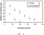
- Table 6 in the presence of the AF-2400X membrane, the formed inhibition zone is much larger than the inhibition zone created when using a PMP membrane. This indicates that AF-2400X allows the penetration of higher amounts of oxygen in comparison to PMP membrane.
- Table 6 UV-Exposure [mJ/cm2] Thickness of Inhibition Zone and STD [ ⁇ m] PMP Thickness of Inhibition Zone and STD [ ⁇ m] AF-2400X 64.9 24 (7) 54 (3.5) 129.8 22 (4.5) 41 (5) 194.8 10 (4.5) 33 (6) 259.7 7 (5) 21 (4)
- a mixture was prepared containing 20 vol% Al 2 O 3 (Almatis A16) (equals 48.1 wt% Al 2 O 3 ), 27.8 wt% radiation curable monomer (Sartomer SR 238), 20.6 wt% radiation curable oligomer (Formlab resin clear), 0.22 wt% of a photo initiator (Irgacure 819), and 3.2 wt% dispersant (Disperbyk-111).
- the mixture was placed in a chamber of an assembly having a similar design as shown in Figures 1A and 1B .
- the transparent window of the chamber was made of oxygen permeable Teflon (AF-2400X) with a thickness of 2.2 mils.
- AF-2400X oxygen permeable Teflon
- electromagnetic radiation unit a lensed UV LED device including an array of 12 UV LEDs, each LED having a maximum optical power of 5.6 Watt and a UV wavelength maximum at 405 nm, and positioned below the transparent window of the chamber.
- a mask having a round opening with a 3 mm inner diameter.
- a carrier plate attached to a vertically movable construction was placed into the mixture of the chamber at a distance of about 10 ⁇ m above the surface of the transparent window.
- the mixture was radiated with the UV LEDs, and with a minor time delay of about 1 to 2 seconds, the carrier plate was started to continuously move upwards, pulling a rod-shaped body out of the mixture.
- the experiment was repeatedly conducted at different continuous forming speeds, such as 30 mm/hour, 60 mm/hour, and 90 mm/hour, as well as at different UV exposures (see Table 7).
- Table 7 Forming Speed [mm/hour] UV Power [mW/cm 2 ] 30 1.12 60 1.12 90 0.56
- FIG. 6 A picture of the rod-shaped body formed at a speed of 1.5 mm/min and a UV power of 0.56 mW/cm 2 is shown in FIG. 6 .
- FIG. 7 A comparison of the formed three-dimensional bodies at different UV exposure and different forming speeds can be seen in FIG. 7 . The best quality could be obtained at the highest forming speed of 90 mm/hour and the lower UV power of 0.56 mW/cm 2 .
- a mixture was prepared with the same components as in Example 4, but by increasing the amount of Al 2 O 3 to 35 vol% (corresponding to 66.1 wt%).
- the exact formulation was as follows: 66.61 wt% Al 2 O 3 (A16 Almatis), 17.52 wt% radiation curable monomer (Sartomer SR 238), 13.07 wt% radiation curable oligomer (Formlab resin clear), 0.29 wt% of a photo initiator (Irgacure 819), and 2.52 wt% dispersant (Disperbyk-111).
- the mixture was not printable because of a too high viscosity.
- One reason for the high viscosity was the high initial viscosity of the radiation curable oligomer (Formlab resin clear). Based thereon, for the further experiments with mixtures of high solid content (above 25 vol%), no oligomer component was included into the compositions.
- a mixture containing 35 vol% Al 2 O 3 (Almatis A16) was prepared according to the composition as shown in Table 1, mixture E2.
- a three dimensional body was formed according to the same method and system as described in Example 4.
- the body was formed at a speed of 60 mm/hour, but at two different applied UV intensities: 1.76 mW/cm 2 and 7.06 mW/cm 2 .
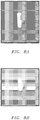
- FIG. 8A at a UV power of 7.06 mW/cm 2 , a dense cylinder could be formed with a desired smooth outer surface.
- the quality of the formed cylinder was not satisfying, showing hollowed out portions and portions which were not fully cured ( FIG. 8B ).
- a mixture containing 30 vol% silica was prepared according to the composition shown in Table 1, mixture E4.
- a three dimensional body was formed according to the same method and system as described in Example 4.
- the body was formed at a speed of 60 mm/hour, and at two different applied UV intensities: 1.76 mW/cm 2 and 7.06 mW/cm 2 . Cylinders of high quality at both UV powers could be formed (see FIG. 9 ).
- the forming results correspond well with the previously measured high sensitivity D p of the silica comprising mixture (see E4 of Example 1).
- a mixture containing 28 vol% MMA was prepared according to the composition shown in Table 1, mixture E5.
- a three dimensional body was formed according to the same method and system as described in Example 4.
- the body was formed at a speed of 60 mm/hour, and at two different applied UV intensities: 3.53 mW/cm 2 and 7.06 mW/cm 2 .
- a high quality cylinder could be formed at UV power of 3.53 mW/cm 2 .
- the formed cylinder contained undesired ridges, see FIG. 10B . These ridges are attributed to a periodic sticking of the formed body to the oxygen permeable membrane caused by an excess of curing energy, which hinders the forming of a functioning inhibition zone (see Example 2).
- a mixture containing 27.6 vol% zirconia was prepared according to the composition shown in Table 1, mixture E3.
- a three dimensional body was formed according to the same method and system as described in Example 4.
- the body was formed at a speed of 60 mm/hour, and at two different applied UV intensities: 7.06 mW/cm2 and 11.76 mW/cm 2 .
- a high quality cylinder could be formed at a UV power of 7.06 mW/cm 2 .
- a proper forming of a body was not possible because the body was sticking to the bottom of the chamber.
- the applied UV power was too high in order to create a functioning inhibition zone.
- Table 8 Summary of Examples 4 to 9: Continuous forming of three-dimensional bodies at a forming speed of 60 mm/ hour with different types of ceramic particles and different light intensities
- Table 8 Example Applied UV power [mW/cm 2 ] Type of Ceramic Amount [vol%] Quality of formed body 4 1.12 Alumina 20 high quality 6 1.76 Alumina 35 low quality / hollowed portions 7 1.76 Silica 30 high quality 8 3.53 MMA 28 high quality 6 7.06 Alumina 35 high quality 7 7.06 Silica 30 high quality 8 7.06 MMA 28 low quality, undesired ridges 9 7.06 Zirconia 27.6 high quality 9 11.76 Zirconia 27.6 no forming possible, sticking to bottom of chamber
- the cure depths of the mixtures E8, E9, and E10 were measured with increasing UV exposure and the curing sensitivity D p for each mixture were calculated from the slope of the linear curves (see FIG. 12 ).
- the slopes for all tested mixtures are very similar, which indicates that the curing sensitivities D p of the mixtures varied only minor with the changing amounts of solid loadings, i.e., being 508 ⁇ m (for E8), 489 ⁇ m (for E9), and 371 ⁇ m (for E10).
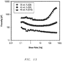
- mixture E8 showed a shear thinning behavior
- mixtures E9 and E10 showed a shear thickening behavior
- Three dimensional bodies were formed from mixtures E8, E9, and E10 according to the same method and system as described in Example 4.
- the bodies were formed at a speed of 60 mm/hour, and at a UV intensity of 7.06 mW/cm2.
- a high quality cylinder was formed from mixture E8, however, cylinders with inferior quality were formed with mixtures E9 and E10, which included hollow parts.
- a summary of the experiments is shown in Table 9.
- the quality differences between the formed bodies of mixtures E8, E9, and E10 indicate that advantageous for the forming of a high quality body is a shear thinning behavior of the mixtures.
- Table 9 Type of solid particle s Amount of SiO 2 [vol%] Amount of SiO 2 [wt.%] Viscosity [cP] at shear rate 1 s -1 Viscosity [cP] at shear rate 100 s -1 Viscosity behavior Quality of printed body E8 SiO 2 30 51.49 70 40 shear thinning high quality E9 SiO 2 40.3 64.15 150 150 shear thickening inferior quality E1 SiO 2 45.2 68.62 490 900 shear thickening inferior quality
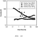
- mixture E11 Three mixtures were prepared containing alumina particles in an amount of 35 vol% but with varying average particle size, i.e., 500 nm (mixture E11), 2 ⁇ m (mixture E12), and 10 ⁇ m (mixture E13). All mixtures further contained monomer (Sartomer SR238), photoinitiator (Irgacure 819), and dispersant Dysperbyk-111).
- mixture E13 had the highest sensitivity, its viscosity behavior made it unsuitable for printing a body.
- the viscosity measurement are shown in FIG. 15 :
- Mixture E11 showed a shear thinning behavior, and slurry E12 showed an almost Newtonian behavior with a very low viscosity.
- slurry E13 had a high viscosity at low shear rates and showed chaotic measurements over a larger viscosity range.
- Mixture E13 also showed a very rapid settling behavior (within a few minutes).
- a three dimensional flower-shaped green body was formed using the same mixture and method as described in Example 2 (alumina comprising mixture, E2) The flower-shaped body was formed at a speed of 60 mm/hour, and an applied UV intensity of 6 mW/cm 2 (see FIG. 17 ).
- the following de-binding and sintering regime was applied: Heating at a rate of 1°C/min up to 325°C; holding the temperature for 30 minutes at 325°C, heating at rate of 1°C/min up to 650°C; holding the temperature for 1 hour at 650°C; heating at a rate of 5°C/min up to 1480°C; holding the temperature for 30 minutes at 1480°C; heating at a rate of 1°C/min up to 1550°C; holding the temperature for 1 hour at 1550°C; cooling down at a rate of 5°C/min to room temperature.
- FIG. 17A shows an example of a flower-shaped green body before high temperature sintering
- FIG. 17B shows flower-shaped ceramic bodies after high temperature sintering
- the microstructure of the sintered ceramic flower was investigated using Scanning Electron Microscope (SEM) technology. Apart of a few minor surface delaminations, no larger cracks or defects could be observed.
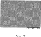
- Cross-sections of individual posts of the flower were polished and thermally etched at 50°C below the maximal sintering temperature for 30 minutes. As can be seen in FIG. 18 , the cross-section shows a high and uniform density throughout the part with a grain size in the range of 0.5 to 10 microns.
- the high density of the sintered ceramic flower was also confirmed by Archimedes and Helium picnometry methods.
- the average density was 92.7% of the theoretical density of alumina if measured by the Archimedes method, and 93% of the theoretical density was measured with the Helium pycnometry method.
Landscapes
- Chemical & Material Sciences (AREA)
- Engineering & Computer Science (AREA)
- Ceramic Engineering (AREA)
- Manufacturing & Machinery (AREA)
- Materials Engineering (AREA)
- Structural Engineering (AREA)
- Organic Chemistry (AREA)
- Physics & Mathematics (AREA)
- Inorganic Chemistry (AREA)
- Optics & Photonics (AREA)
- Mechanical Engineering (AREA)
- Composite Materials (AREA)
- Health & Medical Sciences (AREA)
- Civil Engineering (AREA)
- Electromagnetism (AREA)
- Toxicology (AREA)
- Oral & Maxillofacial Surgery (AREA)
- Thermal Sciences (AREA)
- Producing Shaped Articles From Materials (AREA)
- Polymerisation Methods In General (AREA)
Abstract
Description
- The present disclosure relates to a method for continuously forming a three-dimensional body from a mixture, the mixture comprising solid particles and a radiation curable material.
- The manufacturing of polymeric three-dimensional bodies based on a layer by layer built up of a radiation curable liquid material has become of increasing interest, especially in view of the enhancement in production speed if a bottom-up technique is employed.
- Although it is known that ceramic bodies may also be manufactured via a layer by layer construction of radiation curable ceramic slurries, the production speed for making these materials is still very slow and improvement of the uniformity, density and strength of manufactured ceramic bodies is desirable. The manufacturing of complex three dimensional structures including ceramic can find applications in a wide range of fields, for example, in the automotive and aerospace industry, or in medicine for the making of custom implants and dental models.
- According to one embodiment, a method of forming a body comprises forming a three-dimensional body from a mixture, the mixture comprising at least 15 vol% of solid particles for a total volume of the mixture and a radiation-curable material, wherein forming includes continuous translation and growth of the body from an interface of the mixture.
- According to another embodiment, a method of forming a body comprises providing an assembly including a chamber containing a mixture and a construction; forming a three-dimensional body by continuously creating and attaching a radiation cured translating portion to a carrier plate of the construction and increasing a distance between the carrier plate and the mixture in a continuous manner to create a three-dimensional body within the mixture, wherein during forming the three-dimensional body is adjacent to an interface of an inhibition zone of the mixture. The mixture comprises a mixture characteristic selected from the group of a shear-thinning slurry; a shear-thinning slurry with a radiation-curable material; a content of solid particles of at least 15 vol% for a total volume of the mixture; a yield point of less than 10 Pa; a viscosity of at least 50 cP at a shear rate of less than about 5 Hz, and a viscosity of less than 1000 cP at a shear rate greater than about 25 Hz; or a combination thereof.
- According to a further embodiment, a method of forming a body comprises forming a three-dimensional body using an additive manufacturing process, the three-dimensional body having a content of ceramic particles of at least 15 vol% for a total volume of the three-dimensional body, wherein the three-dimensional body has a total volume of at least 0.1 mm3, and wherein creating is completed at a rate of at least 25 mm/hr.
- The present disclosure may be better understood, and its numerous features and advantages made apparent to those skilled in the art by referencing the accompanying drawings.
-
FIG. 1A includes an illustration of an assembly according to one embodiment, showing the starting phase of forming of a three-dimensional body. -
FIG. 1B includes an illustration of an assembly according to one embodiment, showing a later phase of forming of a three-dimensional body. -
FIG. 2A includes an illustration of a bottom portion of the assembly according to one embodiment. -
FIG. 2B includes an illustration of a bottom portion of the assembly according to an embodiment. -
FIG. 3 is a graph showing the cure depth with increasing UV exposure of mixtures containing each a different type of ceramic particles and of a mixture without ceramic particles. -
FIG. 4 is a graph showing the thickness of the inhibition zone in dependence to the UV exposure of a mixture containing ceramic particles according to one embodiment and of a mixture without ceramic particles. -
FIG. 5 is a graph comparing two types of oxygen permeable membranes with regard to the thickness of an inhibition zone formed during varying UV exposure according to embodiments. -
FIG. 6 is an image of a continuously formed three-dimensional green body comprising alumina particles according to one embodiment. -
FIG. 7 is an image comparing continuously formed three-dimensional green bodies comprising alumina particles according to embodiments. -
FIG. 8A is an image of a continuously formed green body comprising alumina particles according to one embodiment. -
FIG. 8B is an image of a continuously formed green body comprising alumina particles as a comparative example. -
FIG. 9 is an image of a continuously formed green body comprising silica particles according to one embodiment. -
FIG. 10A is an image of a magnified surface structure of a continuously formed green body comprising MMA particles according to one embodiment. -
FIG. 10B is an image of a magnified surface structure of a continuously formed green body comprising MMA particles as a comparative example. -
FIG. 11 is an image of a continuously formed three-dimensional green body comprising zirconia particles according to one embodiment. -
FIG. 12 is a graph comparing cure depth with increasing UV exposure of mixtures with different amounts of silica particles. -
FIG. 13 is a graph comparing viscosity with increasing shear rate of mixtures with different amounts of silica particles. -
FIG. 14 is an image comparing continuously formed three-dimensional green bodies from mixtures with different silica content. -
FIG. 15 is a graph comparing cure depth with increasing UV exposure of mixtures with different alumina particle sizes. -
FIG. 16 is a graph comparing viscosity with increasing shear rate of mixtures with different alumina particle sizes. -
FIG. 17A is an image of a continuously formed flower shaped green body comprising alumina particles according to one embodiment. -
FIG. 17B is an image of a continuously formed flower shaped ceramic body after high temperature sintering according to one embodiment. -
FIG. 18 is an image of a polished cross-section of an individual post of the flower shaped ceramic body ofFIG. 17B after high temperature sintering according to one embodiment. - As used herein, the terms "comprises," "comprising," "includes," "including," "has," "having" or any other variation thereof, are intended to cover a non-exclusive inclusion. For example, a process, method, article, or apparatus that comprises a list of features is not necessarily limited only to those features but may include other features not expressly listed or inherent to such process, method, article, or apparatus.
- As used herein, and unless expressly stated to the contrary, "or" refers to an inclusive-or and not to an exclusive-or. For example, a condition A or B is satisfied by any one of the following: A is true (or present) and B is false (or not present), A is false (or not present) and B is true (or present), and both A and B are true (or present).
- Also, the use of "a" or "an" are employed to describe elements and components described herein. This is done merely for convenience and to give a general sense of the scope of the invention. This description should be read to include one or at least one and the singular also includes the plural unless it is obvious that it is meant otherwise.
- As used herein, the term mixture refers to a fluid of a certain viscosity, including a liquid component and solid particles. The liquid component may include a radiation curable material.
- As used herein, the term three dimensional body refers to a body containing radiation cured resin and at least 15 vol% solid particles based on the total volume of three dimensional body. In the embodiments that the solid particles are ceramic particles, the three dimensional body is also called green body as a synonymous expression, as long it is before the stage of high temperature sintering (before removal of the cured resin).
- Various embodiments of the present disclosure will now be described, by way of example only, with reference to the accompanying drawings.
- The present disclosure relates to a method of continuously forming a three-dimensional body from a mixture. The mixture can comprise solid particles in an amount of at least 15 vol% and a liquid radiation-curable material, wherein the forming includes continuous translation and growth of the three-dimensional body from an interface of the mixture.
- The method includes providing an assembly designed for working with radiation curable mixtures containing a particular concentration of solid particles. As demonstrated in the embodiment shown in
FIG. 1A , the assembly can have a computer controlled electromagnetic radiation unit (11), a chamber (12), and a construction unit (13). The electromagnetic radiation unit (11) can include a UV or visible light (14) emitting radiation source, for example, a laser or a light emitting diode (led) and may project a varying CAD/CAM created two-dimensional image onto a transparent window (15) at the bottom of the chamber (12). The chamber (12) can include a mixture (16) that can include a radiation curable material and solid particles. The transparent window (15) of the chamber can also be semipermeable for an inhibitor gas or may include an additional semipermeable layer (not shown) for the penetration of an inhibitor, for example oxygen, into the mixture (16) of the chamber (12). During the forming process, the inhibitor may enter the chamber (12) by permeating the transparent window (15) and form an inhibition zone (17) at a bottom region of the mixture (16). In the inhibition zone (17) the inhibitor can limit or prevent curing of the mixture (16) by the electromagnetic radiation. - According to one embodiment, a carrier plate (18) can be positioned above the chamber (12). The position between the carrier plate (18) and the mixture in the chamber (12) can be changed during the forming process to facilitate formation of the three-dimensional body. When the formation of the three-dimensional body is started, the carrier plate (18) can be emerged into the mixture (16) up to a pre-calculated distance from the interface of the inhibition zone (22). According to one embodiment, the pre-calculated distance corresponds to a portion of the mixture that can be radiation cured (translated from liquid to solid state) if subjected to electromagnetic radiation from the radiation unit (11) underneath the chamber (12), and is furtheron called "translating portion" (19). The radiation cured translating portion (19) can adhere to the carrier plate (18) and be vertically moved away from the interface of the inhibition zone (22). Concurrently with the upwards movements of the carrier plate (18) and the attached solidified translating portion (19), mixture (16) from the sides of the polymerization chamber or from a reservoir (20) can fill the released space. The construction is designed to move the carrier plate (18) continuously upwards in z direction at a speed that corresponds to the time needed for radiation curing mixture (16) that replaces the upwards moved solidified translating portion.
-
FIG. 1B demonstrates an embodiment including a partially formed three-dimensional body (21) having three solidified and unified translating portions and one translating portion (19) which is subjected to radiation curing and attached to the three-dimensional body (21). - The increase in distance between the carrier plate (18) and the mixture (16) when forming the three-dimensional body (21) can be caused by moving either the carrier plate (18) or the chamber (12) or both carrier plate (18) and chamber (12) in relation to each other.
- The carrier plate (18) of the assembly of the present disclosure is configured for continuous movement to facilitate formation of the three-dimensional body away from the interface of the inhibition zone (22). As used herein, the phrase "interphase of the inhibition zone" (22) can be used interchangeable with the phrase "interface of the mixture," since the inhibition zone is a zone of the mixture, which only distinguishes from the other part of the mixture by the presence of an inhibitor in a concentration that the mixture may not cure if exposed to electromagnetic radiation. Actual solidification and forming of the three dimensional body starts at the interface of the inhibition zone (22), i.e., an interface of the mixture.
- The formation of the three dimensional body may not necessarily be considered a layer-by-layer forming process. Instead, the forming process (e.g., curing) may be in the form of a gradient of solidification (e.g., polymerization). The processes of the embodiments herein may facilitate formation of a three-dimensional body having smoother features and may have improved mechanical properties, compared to conventional structures formed by layer-by-layer forming processes.
- As used in the context of the present disclosure, continuous translation and growth of the three-dimensional body means that the carrier plate (18) can be moved in a continuous manner or in discrete steps with short stops between each step, as long the stops allow that a gradient of solidification is maintained while forming the three-dimensional body. A gradient of solidification means that especially in the translating portion (19) a continuous polymerization reaction is maintained, with the highest degree of solidification at the farthest distance to the inhibition zone. The three-dimensional body formed by the process of continuous translation can thereby possess a non-layered internal structure, such that in a crosscut along the z-axis, changes in the morphology of the green body are not visible to the naked eye. In comparison, traditional layer by layer build-up of a green body waits until one layer is completely radiation cured before the next layer is applied, which leaves visible cleavage lines in the formed green body, i.e., regions that are not smoothly connected together.
- In embodiments, the stops in the movement of the carrier plate (18) while conducting continuous translation and forming of the three-dimensional body can be at least 1 microsecond, such as at least 300 microseconds, at least 500 microseconds, at least 800 microseconds, or at least 1000 microseconds. In other embodiments, the stops during continuous translation may be not longer that 1 second, such as not longer than 0.5 seconds, not longer than 0.3 seconds, not longer than 0.2 seconds, or not longer than 0.1 seconds. It will be appreciated that the stops during continuous translation can be a value within any of the minimum and maximum values note above, such as from 1 microsecond to 1 second, from 300 microseconds to 0.5 seconds, or from 1000 microseconds to 0.1 seconds.
- In further embodiments, the method of the present disclosure can also include one or more longer stops during the forming of the three-dimensional body, such that the gradient of solidification may be interrupted and the translation is not continuous as defined above. Such longer stops may be desired for the making of a body having defined regions which are cleavable.
- The cure depth of the electromagnetic radiation (14) applied to the mixture (16) may be effected by the size, type, and concentration of the solid particles and the refractive index of the particle slurry. Notably, the size and concentration of the solid particles may be particularly selected to facilitate proper operation of the process in combination with the type of electromagnetic radiation used for the curing process.
- According to an embodiment, suitable formation of a three-dimensional body having a suitable strength, can include controlling the cure depth relative to a thickness of the translating portion. In one embodiment, the cure depth may be at least 25% larger than the thickness of the translating portion (19), such as at least 30%, at least 35%, or at least 40%. In another embodiment, the cure depth can be not greater than 75% of the thickness of the translating portion (19), such as not greater than 70% or not greater than 65%. It will be appreciated that the cure depth can be a value between any of the maximum and minimum values noted above, such as from 25% to 75%, from 30% to 70% or from 35% to 60% of the thickness of the translating portion (19).
- In one embodiment, a thickness of the translating portion (19) can be at least 50 µm, such as at least 70 µm, or at least 100 µm. In another embodiment, the thickness of the translating portion may be not greater than 500 µm, such as not greater than 450 µm, or not greater than 400 µm. It will be appreciated that the thickness of the translating portion can be a value between any of the maximum and minimum values note above, such as from 50 µm to 500 µm, from 80 µm to 450 µm, or from 100 µm to 300 µm.
- In a further aspect, the cure depth may be at least 1 µm larger than the thickness of the inhibition zone (17), such as at least 5 µm, at least 10 µm, at least 20 µm, or at least 50 µm larger than the thickness of the inhibition zone. In yet another aspect, the cure depth can be not greater than 400 µm than the thickness of the inhibition zone, such as not greater than 350 µm, not greater than 300 µm, or not greater than 250 µm than the thickness of the inhibition zone. It will be appreciated that the cure depth can be a value between any of the maximum and minimum values noted above, such as within a range of at least 1 µm to not greater than 400 µm, from 5 µm to 370 µm, or from 30 µm to 300 µm larger than the thickness of the inhibition zone.
- The thickness of the inhibition zone (17), which can be formed when the inhibitor enters the chamber (12) through the transparent and semipermeable window, (15) may be regulated by the concentration of the inhibitor. The inhibition zone (17) may limit the curing of the mixture (16) in that zone within the chamber (12). The inhibition zone (17) may facilitate limited or no adhesion of the radiation cured material to the bottom of the chamber (12), which may further facilitate simpler release of the body from the chamber after forming is completed.
-
Figures 2A and 2B show embodiments how a semipermeable layer can be integrated at the bottom section of the chamber. In the embodiment ofFIG. 2A , the transparent window (24) functions also as a semipermeable layer for the penetration of the inhibitor gas (25), penetrating the transparent window (24) from the bottom of the chamber.FIG. 2B shows an embodiment where an additional semipermeable layer (26) is installed above the transparent window (24) and the inhibitor gas (25) is provided from the sides of the polymerization chamber. - In one embodiment, the thickness of the semipermeable layer for the penetration of inhibitor gas can be at least about 1 µm, such as at least about 5 µm, at least about 50 µm, at least about 500 µm, or at least about 1000 µm. The upper thickness of the semipermeable layer may not be limited as long the layer allows sufficient transport of inhibitor gas.
- The material of the semipermeable layer may be any material that permits the penetration of inhibitor gas. Non-limiting examples of materials suitable for a semipermeable layer can include, for example, fluoropolymers, such as Teflon (e.g., AF-2400X), polymethylpentene based membranes (PMP), or silicone polymers and copolymers.
- The inhibitor may preferably be an oxygen containing gas, such as air, mixtures of an inert gas and oxygen, or pure oxygen. In another aspect, when oxygen cannot inhibit the activity of the photoinitiator (for example, when a cationic photoinitiator is used) the inhibitor can be an amine, e.g., ammonia, ethyl amine, di and trialkyl amines, carbon dioxide, or combinations thereof.
- In one embodiment, the inhibitor can be pure oxygen, and the oxygen may penetrate the semipermeable layer in an amount of at least 0.1 Barrer, such as at least 1 Barrer, at least 5 Barrer, at least 10 Barrer, or at least 30 Barrer.
- The thickness of the inhibition zone should be at least in the range of the average size of the solid particles contained in the mixture or greater. In one embodiment, the thickness of the inhibition zone may be at least 0.5 µm, such as at least 1.0 µm, at least 2.0 µm, or at least 5 µm. In another embodiment, the inhibition zone may not be greater than 600 µm, such as not greater than 500 µm, not greater than 300 µm, or not greater than 100 µm. It will be appreciated that the thickness of the inhibition zone can be a value between any of the maximum and minimum values noted above, such as from 0.5 µm to 600 µm, from 1.0 µm to 450 µm, or from 3 µm to 200 µm.
- Although the term "inhibition zone" appears to indicate that no polymerization reaction may take place in that area of the mixture, it will be appreciated that polymerization reactions can also occur to a limited extent in the inhibition zone. The inhibition zone may be also described as a gradient of polymerization, where with increasing distance from the bottom surface of the chamber larger amounts of polymerization reactions can happen, but these polymerization reactions may not completely cure the mixture, and the mixture is still maintained in a liquid stage. The interface of the inhibition zone may be understood as the area of the inhibition zone where the polymerization reactions start to form a solid material.
- The solid particles contained in the mixture can be any type of inorganic or organic particles that do not dissolve in the liquid component of the mixture under the forming conditions, and may be uniformly distributed throughout the entire mixture. In one aspect, the solid particles can be ceramic particles, metallic particles, polymeric particles, or any combination thereof.
- In a particular embodiment, the solid particles can be ceramic particles, such as an oxide, a carbide, a boride, a nitride, a silicide or any combination thereof. Non-limiting examples or ceramic particles can be alumina, ceria, zirconia, silica, magnesium-magnesia aluminate (MMA), magnesium oxide, silicon nitride, silicon carbide, hydroxyapatite, cordierite, or any combination thereof. In a particular embodiment, the ceramic particles are alumina, silica, MMA, or zirconia.
- The concentration of the solid particles in the mixture can be in a range that a percolated network be formed and that the created three-dimensional body can be densified without falling apart upon burnout of the binder. In one embodiment, the concentration of solid particles can be at least 15 vol%, such as at least 16 vol%, at least 18 vol%, at least 20 vol%, at least 25 vol%, or at least 30 vol%. In another embodiment, the particle concentration can be not greater than 80 vol%, such as not greater than 75 vol%, not greater than 70 vol%, or not greater than 65 vol%. It will be appreciated that the concentration of solid particles can be a value between any of the maximum and minimum values noted above, such as from 16 vol% to 80 vol %, from 20 vol% to 75 vol%, or from 30 vol% to 65 vol%.
- The solid particles contained in the mixture can have an average particle size of at least 0.1 µm, such as at least 0.5 µm, at least 1.0 µm, or at least 5 µm. In another aspect, the solid particles can have an average particle size of not greater than 20 µm, such as not greater than 18 µm, or not greater than 15 µm. It will be appreciated that the average size of the solid particles can be a value between any of the maximum and minimum values noted above, such as from 0.1 µm to 20 µm, 0.3 µm to 18 µm, or 0.5 µm to 15 µm.
- In one embodiment, the solid particles may have a multimodal particle distribution, for example, a bimodal or trimodal particle distribution.
- In order to provide a high quality of the formed three-dimensional body of the present disclosure, it can be advantageous if solid particles that exceed a certain particle size or particles that have a size below a certain minimum be excluded. In one embodiment, the solid particles may have a particle size distribution wherein a value of function (d50-d10)/d50 is less than 0.8. In another embodiment, the solid particles may have a particle size distribution wherein a value of function (d90-d50)/d50 is less than 1.0.
- In another embodiment, the solid particles contained of the mixture may have an average particle size controlled relative to the thickness dimension of the inhibition zone. In a preferred aspect, an average particle size of the solid particles may not be greater than 25% of the thickness of the inhibition zone, such as not greater than 20%, not greater than 15%, or not greater than 10% of the thickness of the inhibition zone.
- In one embodiment, the mixture can contain at least 20 vol% to 40 vol% ceramic particles and may be radiation cured with UV radiation having an energy of at least 30 mJ/cm2 and not greater than 200 mJ/cm2.
- The radiation curable material contained in the mixture can comprise polymerizable monomers, polymerizable oligomers and one or more photoinitiators. In a preferred aspect, the radiation curable material can contain polymerizable monomers and at least one photoinitiator. Suitable polymerizable monomers can be, for example, acrylates, acrylamides, urethanes, dienes, or combinations thereof.
- The photoinitiator can be a free-radical photoinitiator or a cationic photoinitiator. In a preferred aspect, a free-radical photoinitiator can be employed, which can be inhibited by the presence of oxygen. Non-limiting examples of free-radical photoinitiators can include peroxides, such as acetyl, benzoyl, t-butyl peroxides, ketones or phosphine oxides, such as IRGACURE 819 (bis(2,4,6-trimethylbenzoyl)-phenylphosphineoxide), ESSTECH TPO (2,4,6-trimethylbenzoyl)-phenylphosphineoxide) or a combination thereof.
- In an embodiment where a cationic photoinitiator is used, the photopolymerization generally tends to be slower and cannot be inhibited by oxygen. In this aspect, instead of oxygen as inhibitor, a Bronsted acid or Lewis acid, such as metal halides and their organometallic derivatives can be employed and released from the bottom window of the polymerization chamber to form an inhibition zone.
- The mixture comprising the solid particles and the radiation curable material can be subjected to electromagnetic radiation having a wavelength in a range from 200 nm to 760 nm, depending from the activation energy of the selected photoinitiator. In a preferred aspect, the range of the electromagnetic radiation may be from 370 nm to 450 nm, or from 380 nm to 410 nm.
- In embodiments, the electromagnetic radiation can be created by a laser, a light emitting diode (led), or by electron beam radiation.
- In one embodiment, the electromagnetic radiation applied for curing the mixture can have an energy of at least 20 mJ/cm2, such as at least 30 mJ/cm2, at least 50 mJ/cm2 or at least 80 mJ/cm2. In another embodiment, the electromagnetic radiation can have an energy not greater than 450 mJ/cm2, such as not greater than 400 mJ/cm2, not greater than 350 mJ/cm2, not greater than 300 mJ/cm2, not greater than 250 mJ/cm2, not greater than 200 mJ/cm2, or not greater than 100 mJ/cm2. It will be appreciated that the electromagnetic radiation energy can be a value between any of the maximum and minimum values noted above, such as from 20 mJ/cm2 to 450 mJ/cm2, from 30 mJ/cm2 to 300 mJ/cm2, from 40 mJ/cm2 to 200 mJ/cm2, or from 20 to 100 mJ/cm2.
- In a particular embodiment, the method of the present disclosure may cure the mixture in the translation portion (19) during continuous forming of the three dimensional body at a UV power of at least 0.1 mW/cm2, such as at least 0.5 mW/cm2, at least 1.0 mW/cm2, or at least 3.0 mW/cm2. In another particular embodiment, the applied UV power during forming may be not greater than 250 mW/cm2, such as not greater than 150 mW/cm2, not greater than 100 mW/cm2, not greater than 50 mW/cm2, not greater than 30 mW/cm2, not greater than 20 mW/cm2, not greater than 13.0 mW/cm2, not greater than 12 mW/cm2, or not greater than 10 mW/cm2. It will be appreciated that the applied UV power can be a value between any of the maximum and minimum values noted above, such as from 0.1 mW/cm2 to 250.0 mW/cm2, from 1.0 mW/cm2 to 100 mW/cm2 or from 2.0 mW/cm2 to 10 mW/cm2.
- In a further embodiment, the thickness dimension of the inhibition zone can be controlled relative to the concentration of the solid particles. By increasing the concentration of the solid particles, the thickness of the inhibition zone may be decreased, as also shown in Example 2.
- In another embodiment, the solid particles contained in the mixture can include a coating overlying an exterior surface of the particles. The coating can partially or completely cover the surface of the solid particles. The coating may be desirable in order to adjust the scattering and/or absorption of an applied electromagnetic radiation in the mixture. In one aspect, the coating can provide a 50% lower scattering of an applied electromagnetic radiation than corresponding uncoated particles. In a further aspect, the coating can lower the radiation scattering by at least 55%, such as at least 60%, at least 70%, at least 80%, at least 90% or at least 95%.
- In another aspect, a coating of the solid particles can provide a 50% lower absorbance of an applied electromagnetic radiation absorption than corresponding uncoated particles. In embodiments, the coating can lower the radiation absorbance in the mixture by at least 55%, such as at least 60%, at least 65%, at least 70%, at least 75%, at least 80%, at least 90% or at least 95%.
- According to another embodiment of the present disclosure, the mixture may include one or more additives. Non-limiting examples of additives can be additional inhibitors to prevent spontaneous polymerization (inert dyes), plasticizer, dispersing agents, debinding accelerators, cross-linking monomers, pH regulators, a pharmaceutically active ingredient, or any combination thereof.
- The rheological properties of the mixture containing solid particles and a radiation curable material may be controlled to facilitate suitable formation of a stable and suitably formed three-dimensional body, including for example, a ceramic green body having sufficient strength to be self-supporting and capable of handling without detrimental deformation. Also, the force required to continuously pull-up the carrier the force utilized to pull the carrier plate away from the chamber may be adjusted based on various parameters, including but not limited to the rheology of the mixture.
- In a particular embodiment, the mixture used for forming the three dimensional body according to the present disclosure can be characterized that the viscosity of the mixture decreases with increasing shear rate. Such type of mixture is also called herein a shear thinning slurry. In certain embodiments, the decrease of the viscosity of the mixture from a shear rate of 0.1 s-1 to a shear rate of 500 s-1 can be at least 10 cP, such as at least 30 cP, at least 50 cP, or at least 80 cP. In other embodiments, the decrease in viscosity from a shear rate of 0.1 s-1 to a shear rate of 500 s-1 may be not greater than 1500 cP, such as not greater than 1200 cP, not greater than 1000 cP, or not greater than 800 cP. It will be appreciated that the decrease in viscosity from a shear rate of 0.1 s-1 to a shear rate of 500 s-1 may be a value within any of the maximum and minimum values noted above, such as from 10 cP to 1500 cP, from 50 cP to 700 cP, or from10 cP to 100 cP.
- In another aspect, the yield point of the mixture may be less than 10 Pa, such as less than 8 Pa, less than 5 Pa, or less than 3 Pa at room temperature.
- In a further aspect, the mixture may have a low shear viscosity to prevent particle settling over the duration of the forming of the three-dimensional body. Furthermore, the solid particles contained in the slurry may be uniformly dispersed throughout the radiation curable material when electromagnetic radiation is conducted such that that the three-dimensional body can shrink uniformly during sintering. Nonuniform distribution of the solid particles may result in undesirable macro-structural or micro-structural features, including for example, undesirable porosity and the like. Under low shear rate may be understood a range of not greater about 5 Hz and at least about 0.001 Hz, with a corresponding viscosity from at least about 50 cP to not greater than about 5000 cP, particularly from at least 70 cP to not greater than 1500 cP. In one aspect, the viscosity at a low shear rate of less than about 5 Hz can be at least 100 cP.
- The viscosity at a moderate to high shear rate can enable sufficient spontaneous flow of the mixture between carrier plate and the bottom surface of the polymerization chamber. Under moderate to high shear rate may be understood a shear rate in a range from at least about 25 Hz and not greater than about 3000 Hz, with a corresponding viscosity of the mixture in a range of at least 1 cP and not greater than 1000 cP. In one aspect, the viscosity of the mixture at a moderate to high shear rate of greater than 25 Hz may be less than 1000 cP.
- In one embodiment, the mixture may be formed such that the content of agglomerates of the solid particles is limited. In certain embodiments, the mixture can be essentially free of agglomerates of solid particles. Forming a mixture that has limited agglomerates can include heat treatment and milling of the solid particle powder before combining with the other components of the mixture. In embodiments, the solid particle powder can be heat treated at least 90°C, such as at least 100°C or even at least 105°C.
- Other mixing methods may be employed. The mixing process may be controlled to control the level of agglomeration. Moreover, over-mixing may result in degrading of the monomers and generating too much premature polymerization of the radiation curable resin.
- In one particular embodiment, the mixture can comprise alumina particles having an average particle size from 100 nm to 5000 nm in an amount of 15 vol% to 50 vol%.
- In a certain embodiment, the alumina particles can have an average particle size from 300 nm to 3000 nm and may be present in an amount of 18 vol% to 40 vol%. The alumina containing mixture may be a shear thinning slurry having a viscosity of 1 s-1 at a shear rate of not greater than 900
cP 1, and at viscosity of at least 70 cP at a shear rate of 500 s-1. - In another embodiment, the mixture can comprise at least 30 vol% alumina and the forming of the three dimensional body may be conducted at an applied UV power of at least 3 mW/cm2 and not greater than 12 mW/cm2.
- In a further particular embodiment, the alumina particles can be present the mixture in an amount of 16 vol% to 25 vol%, and the forming of the three dimensional body may be conducted at an applied UV power of at least 1.0 mW/cm2 and not greater than 12 mW/cm2.
- In another particular embodiment, the mixture can comprise silica particles having an average particle size from 100 nm to 5000 nm and in an amount of 15 to 40 vol%. In a certain aspect, the silica particles can have an average particle size from 1000 nm to 3000 nm and may be present in an amount of 25 vol% to 35 vol%, wherein the mixture is a shear thinning slurry having a viscosity of not greater than 200 cP at a shear rate of 1 s-1 and a viscosity of at least 50 cP at a shear rate of 500 s-.
- In a further particular aspect, the method of the present disclosure may employ a mixture comprising at least 25 vol% silica, and the forming of the three dimensional body can be conducted at an applied UV power of at least 1.0 mW/cm2 and not greater than 12 mW/cm2.
- According to an embodiment, the mixture may be essentially free of a dye. In this embodiment, the mixture may be formed with solid particles having the proper combination of concentration, average particle size, and coating on the solid particles. A mixture being essentially free of a dye relates to a dye concentration of less than 0.001 vol%. In contrast, radiation curable mixtures which do not contain solid particles and are fully polymer-based, generally require a dye in order to control unwanted photopolymerization.
- The total volume of the three-dimensional body created by the process of the present disclosure can be at least 0.1 mm3, such as at least 0.3 mm3, at least 0.5 mm3 or at least 1 mm3. If the process of the present disclosure employs a replenishable reservoir, as shown in
Figure 1 , the method may not have a specific upper limit of the total volume of the formed three-dimensional body. For example, in one embodiment, interconnected parts can be formed and directly fed into a furnish, whereby no specific upper limit of the body volume may exist. - The method of the present disclosure can be further characterized by producing three-dimensional bodies from mixtures having a high content of solid particles, whereby the formed bodies can have an exceptional uniform structure, high strength and high smoothness.
- In one embodiment, the method of the present disclosure is characterized that a three-dimensional body including ceramic particles can be continuously manufactured at a high production speed. In one aspect, the creating of the three dimensional body can be completed at a speed rate of at least 25 mm/hr, such as at least 30 mm/hr, at least 40 mm/hr, at least 50 mm/hr, or at least 70 mm/hr.
- In a particular embodiment, the three dimensional body of the present disclosure can be subjected to high temperature sintering to remove the radiation curable material and to form a sintered body. If the solid particles of three dimensional body subjected to high temperature sintering are ceramic particles, the sintered body is called hereafter a ceramic body.
- The sintering temperature can be at least 900°C, such as at least 950°C, at least 1000°C, at least 1050°C, at least 1100°C, or at least 1150°C. In other aspects, the sintering temperature can be not greater than 1600°C, such as not greater than 1550°C, not greater than 1500°C, or not greater than 1400°C. It will be appreciated that the sintering temperature can be a value between any of the minimum and maximum values noted above, such as from 900°C to 1600°C, from 1000°C to 1500°C, or from 1100°C to 1350°C.
- In a certain embodiment, the high temperature sintering can lead to a ceramic body having a density of at least 90% of its theoretical density.
- In particular embodiments, the ceramic body can consist essentially of ceramic particles. In one aspect the ceramic body may consist essentially of alumina. In another aspect, the ceramic body can consist essentially of silica. Consisting essentially of ceramic particles means that the ceramic body comprises at least 99wt% ceramic particles based on the total weight of the ceramic body.
- Many different aspects and embodiments are possible. Some of those aspects and embodiments are described herein. After reading this specification, skilled artisans will appreciate that those aspects and embodiments are only illustrative and do not limit the scope of the present invention. Embodiments may be in accordance with any one or more of the embodiments as listed below.
-
-
Embodiment 1. A method of forming a body comprising:
forming a three-dimensional body from a mixture, the mixture comprising at least 15 vol% of solid particles for a total volume of the mixture and a radiation-curable material, wherein forming includes continuous translation and growth of the body from an interface of the mixture. -
Embodiment 2. A method of forming a body comprising:- providing an assembly including a chamber containing a mixture and a construction;
- forming a three-dimensional body by continuously creating and attaching a radiation cured translating portion to a carrier plate of the construction and increasing a distance between the carrier plate and the mixture in a continuous manner to create a three-dimensional body within the mixture, wherein during forming the three-dimensional body is adjacent to an interface of an inhibition zone of the mixture,
- wherein the mixture comprises a liquid characteristic selected from the group of:
- a shear-thinning slurry;
- a shear-thinning slurry with a radiation-curable material;
- a content of solid particles of at least 15 vol% for a total volume of the mixture;
- a yield point of less than 10 Pa;
- a viscosity of at least 50 cP at a shear rate of less than about 5 Hz, and a viscosity of less than 1000 cP at a shear rate greater than about 25 Hz;
- or a combination thereof.
-
Embodiment 3. The method ofembodiments - Embodiment 4. The method of any of
embodiments 1 to 3, wherein during forming portions of the mixture are subjected to electromagnetic radiation having a wavelength in a range from 200 nm to 760 nm. - Embodiment 5. The method of embodiment 4, wherein the electromagnetic radiation has a wavelength within a range from at least 370 nm to not greater than 450 nm.
- Embodiment 6. The method of embodiments 4 or 5, wherein the electromagnetic radiation has an energy within a range from at least 20 mJ/cm2 to not greater than 450 mJ/cm2.
- Embodiment 7. The method of embodiment 6, wherein the electromagnetic radiation has an energy within a range from at least 20 mJ/cm2 to not greater than 200 mJ/cm2.
- Embodiment 8. The method of embodiment 7, wherein the electromagnetic radiation has an energy within a range from 20 mJ/cm2 to 100 mJ/cm2.
- Embodiment 9. The method of
embodiment 3, wherein the photoinitiator comprises a free-radical photoinitiator. -
Embodiment 10. The method ofembodiment 3, wherein the polymerizable monomer comprises a material selected from the group of acrylates, acrylamides, urethanes, dienes, or a combination thereof. -
Embodiment 11. The method of any of the previous embodiments, wherein the solid particles include ceramic particles, metallic particles, polymeric particles, or any combination thereof. -
Embodiment 12. The method ofembodiment 11, wherein the ceramic particles comprise at least one material selected from the group of an oxide, a carbide, a boride, a nitride, a silicide or a combination thereof. -
Embodiment 13. The method ofembodiment 12, wherein the ceramic particles comprise at least one material selected from the group of alumina, ceria, zirconia, silica, magnesium-magnesia aluminate (MMA), magnesia, silicon carbide, hydroxyapatite, cordierite, or a combination thereof. -
Embodiment 14. The method of any ofembodiment 13, wherein the mixture comprises solid particles selected from the group of alumina, silica, MMA, or zirconia. -
Embodiment 15. The method of any of the previous embodiments, wherein at least a portion of the solid particles include a coating overlying an exterior surface. -
Embodiment 16. The method ofembodiment 15, wherein the coated solid particles provide a 50% lower scattering of an applied electromagnetic radiation than corresponding uncoated particles. -
Embodiment 17. The method ofembodiment 16, wherein the coated solid particles provide a 90% lower scattering of an applied electromagnetic radiation than the corresponding uncoated particles. -
Embodiment 18. The method ofembodiment 15, wherein the coated solid particles provide a 50% lower absorbance of an applied electromagnetic radiation than corresponding uncoated particles. -
Embodiment 19. The method ofembodiment 18, wherein the coated solid particles provide a 90% lower absorbance of an applied electromagnetic radiation than the corresponding uncoated particles. -
Embodiment 20. The method of any of the previous embodiments, wherein the solid particles have an average particle size of at least 0.1 µm and not greater than 20 µm. -
Embodiment 21. The method of any of the previous embodiments, wherein the solid particles have a multimodal particle size distribution. -
Embodiment 22. The method of any of the previous embodiments, wherein the solid particles have a particle size distribution comprising a value of function (d50-d10)/d50 of less than 0.8. - Embodiment 23. The method of any of the previous embodiments, wherein the solid particles have a particle size distribution comprising a value of function (d90-d50)/d50 of less than 1.0.
-
Embodiment 24. The method ofembodiments -
Embodiment 25. The method ofembodiment 24, wherein the inhibition zone has a thickness of at least 0.5 µm and not greater than 600 µm. -
Embodiment 26. The method ofembodiments - Embodiment 27. The method of
embodiments - Embodiment 28. The method of
embodiment 26, wherein the average particle size of the solid particles is not greater than 25% of the thickness of the inhibition zone. - Embodiment 29. The method of embodiment 28, wherein the average particle size of the solid particles is not greater than 10% of the thickness of the inhibition zone.
-
Embodiment 30. The method ofembodiment 2, wherein the chamber further comprises an oxygen-permeable layer. - Embodiment 31. The method of
embodiments - Embodiment 32. The method of any of embodiments 4 to 31, wherein the applied electromagnetic radiation has a power of at least 0.1 mW/cm2, such as at least 0.5 mW/cm2, at least 1.0 mW/cm2, at least 2 mW/cm2, or at least 3 mW/cm2.
- Embodiment 33. The method of any of embodiments 4 to 32, wherein the applied electromagnetic radiation has a power not greater than 250 mW/cm2, such as not greater than 100 mW/ cm2, not greater than 50 mW/ cm2, or not greater than 10mW/cm2.
- Embodiment 34. The method of any of the precedent embodiments, wherein the mixture is a shear thinning slurry.
- Embodiment 35. The method of embodiment 34, wherein the shear thinning slurry is characterized that a decrease in viscosity of the mixture from a shear rate of 0.1 s-1 to a shear rate of 500 s-1 is at least 10 cP, such as at least 30 cP, at least 50 cP, or at least 80 cP.
- Embodiment 36. The method of embodiment 34, wherein shear thinning slurry is characterized that a decrease in viscosity of the mixture from a shear rate of 0.1 s-1 to a shear rate of 500 s-1 is not greater than 1500 cP, such as not greater than 1200 cP, not greater than 1000 cP, or not greater than 800 cP.
- Embodiment 37. The method of any of the precedent embodiments, wherein the mixture comprises alumina particles having an average particle size from 100 nm to 5000 nm in an amount of 15 vol% to 50 vol%.
- Embodiment 38. The method of embodiment 37, wherein the alumina particles have an average particle size from 300 nm to 3000 nm and are present in an amount of 18 vol% to 40 vol%, and wherein the mixture is a shear thinning slurry having a viscosity of not greater than 900 cP at a shear rate of 1 s-1, and at viscosity of at least 70 cP at a shear rate of 500 s-1.
- Embodiment 39. The method of embodiments 37 or 38, wherein the mixture has a viscosity not greater than 150 cP at a shear rate of 500 s-1.
-
Embodiment 40. The method of any of embodiments 37 to 39, wherein the mixture comprises at least 30 vol% alumina and the forming of the three dimensional body is conducted at an applied UV power of at least 3 mW/ cm2 and not greater than 12 mW/ cm2. - Embodiment 41. The method of any of embodiment 37 to 39, wherein the alumina particles are present in an amount of 16 vol% to 25 vol%, and the forming of the three dimensional body is conducted at an applied UV power of at least 1.0 mW/ cm2 and not greater than 12 mW/ cm2.
- Embodiment 42. The method of any of
embodiments 1 to 36, wherein the mixture comprises silica particles having an average particle size from 100 nm to 5000 nm and in an amount of 15 to 40 vol%. - Embodiment 43. The method of embodiment 42, wherein the silica particles have an average particle size from 1000 nm to 3000 nm and are present in an amount of 25 vol% to 35 vol%, and wherein the mixture is a shear thinning mixture having a viscosity of not greater than 200 cP at a shear rate of 1 s-1 and a viscosity of at least 50 cP at a shear rate of 500 s-1.
- Embodiment 44. The method of embodiments 42 or 43, wherein the mixture has a viscosity not greater than 100 cP at a shear rate of 500 s-1.
-
Embodiment 45. The method of any of embodiments 42 to 44, wherein the mixture comprises at least 25 vol% silica and the forming of the three dimensional body is conducted at an applied UV power of at least 1.0 mW/cm2 and not greater than 12 mW/ cm2. - Embodiment 46. The method of any of the precedent embodiments, further comprising subjecting the three dimensional body to high temperature sintering at a temperature of at least 1000°C.
- Embodiment 47. The method of embodiment 46, wherein high temperature sintering forms a ceramic body, the ceramic body having a density of at least 90% of its theoretical density.
- Embodiment 48. The method of embodiment 47, wherein the ceramic body consists essentially of alumina.
- Embodiment 49. The method of embodiment 47, wherein the ceramic body consists essentially of silica.
-
Embodiment 50. The method of any of the precedent embodiments, wherein forming is conducted at a forming speed of at least 25 mm/hr. - Embodiment 51. The method of any of the precedent embodiments, wherein forming is conducted at a forming speed of at least 60 mm/hr.
- Embodiment 52. A method of forming a body comprising:
forming a three-dimensional body using an additive manufacturing process, the three-dimensional body having a content of ceramic solid particles of at least 15 vol% for a total volume of the body, wherein the three-dimensional body has a total volume of at least 0.1 mm3, and wherein forming is completed at a forming speed of at least 25 mm/hr. - Embodiment 53. The method of embodiment 52, wherein the forming speed is at least 60 mm/hr.
- The following non-limiting examples illustrate the present invention.
- Example 1 demonstrates the change in cure depth of UV-radiation curable mixtures with different types of ceramic particles. The ceramic particle powders used in the experiments were alumina, zirconia, silica, magnesium-magnesia aluminate (MMA), silicon nitride, silicon carbide, and graphite.
- Ceramic slurries were prepared for each type of ceramic powder using as radiation curable material for all
samples 1,6 hexanediol diacrylate (Sartomer SR238, hereinafter used as "monomer") and a photoinitiator (Irgacure 819). A summary of the ceramic powder slurries used in the experiments can be seen in Table 1.Table 1: Type of solid particles Aver. particle size Spec. surface area Amount of solid particles [vol%] Amount of solid particles [wt.%] Amount of monomer [wt.%] Amount of photoinitiator [wt.%] Amount of dispersant [wt.%] E1 - - - E2 Al2O3 500 nm 7 35 67.52 29.35 0.59 2.55 E3 ZrO 2 300 nm 7 27.6 69.09 27.14 0.54 3.23 E4 SiO2 1.7 µm 2 30 51.49 45.79 0.91 1.81 E5 MMA 3 µm 1 28 57.89 38.11 0.76 3.23 E6 Si3N4 1.5 µm 9 27.4 55.88 37.99 0.76 5.37 E7 SiC 2 µm 0.47 30 56.91 41.78 0.83 0.47 - All mixtures E2 to E7 contained a dispersant which insured that the ceramic particles did not settle over a time period of at least 1 hour. Table 2 gives a summary of the settling tests performed to select the appropriate dispersant. Three dispersants (Disperbyk-111, Disperbyk-180, Disperbyk-168) were selected on the basis of their potential chemical affinity to the radiation curable monomer. Mixtures of monomer, specific dispersant and powder were prepared and mixed using a resodyn acoustic mixer and were observed thereafter for settling behavior over the period of four days. The efficiency of each dispersant was assessed by visual inspection. Disperbyk-111 was observed to be the most effective dispersant for the alumina slurries, whereas Dysperbyk-168 was the best dispersant for all the other mixtures.

- For the measurement of the cure depth, a chamber was filled with the mixture to be tested (E1 to E7), and the mixture was exposed to a static image made of a series of light dots, wherein the dots differed in their light intensity. The image was projected from a Digital Light Projector connected to a UV lamp (405 nm). The light intensity of each dot was controlled by scaling down the [R G B] intensity of the dots directly on the image. For most curing experiments, the power of the lamp was 30 mW/cm2, and the resin was exposed to the radiation for 60 seconds at a maximum UV exposure of 1800 mJ/cm2 for the dot with the highest light intensity. The thickness of each printed dot was then measured with a micro-caliper to obtain a relationship of cure depth in dependency to the UV exposure.
- As can be seen in Table 3 and
Figure 3 , the presence of ceramic particles (samples E2 to E7) resulted in a much lower cure depth in comparison to the cure depth of the mixture containing no ceramic particles (E1). It can be further seen that there are large differences between the tested mixtures. The highest cure depth was observed for the silica comprising slurries, followed by slurries containing MMA, alumina, zirconia and silicon carbide.Table 3: Cure depth with varying UV exposure for different mixtures UV Exposure [mJ/cm2] Cure depth [µm] E1 E2 E3 E4 E5 E6 E7 247 800 140 66 608 269 - - 388 940 160 86 695 327 40 - 529 900 180 86 770 322 - - 671 1010 190 94 803 349 - - 812 980 200 98 847 354 - - 953 1190 210 105 878 376 50 - 1094 1210 210 111 898 389 - - 1235 1210 220 111 927 398 - - 1376 1280 230 116 958 414 - - 1518 1430 230 118 949 436 - - 1659 1420 240 120 1000 443 - - 1800 1320 250 125 1022 439 59 - 2700 - - - - - 60 <1 3600 - - - - - 66 - 5400 - - - - - 70 1 - It can be further seen from
Figure 3 that the increase in cure depth is linear to the logarithms of the applied radiation energy for all mixtures. The slope of the straight lines for each mixture can be correlated to the curing sensitivity Dp of the mixtures with regard to UV exposure. - Table 4 shows the curing sensitivity Dp values obtained from the slopes of
Figure 3 with regard to the refractive index of the ceramic materials of the mixtures. Not to be bound by theory, the sensitivity values Dp indicate that the curing sensitivity of the mixtures decreases with increasing scattering of the particles and strongly relates to the refractive index of the ceramic particles.Table 4: Example Ceramic Particles Sensitivity Dp [µm] Refractive Index Particle Size Particle Amount [vol%] SSA E1 - 249 1.5* E4 Silica 192 1.5‡ 1700 nm 30 2 E3 MMA 85 1.7‡ 3000 nm 28 <1 E2 Alumina 49 1.8‡ 500 nm 35 7 E5 Zirconia 29 2.2‡ 300 nm 27.6 7 * Monomer ‡ Ceramic particles - Radiation curable mixtures with and without Al2O3 (E4 and E1), have been further compared by measuring the thickness of the inhibition zone for each sample with increasing UV exposure.
- As can be seen in Table 5 and
Figure 4 , the presence of 35 vol% Al2O3 lowered the thickness of the inhibition zone to a large extent in comparison to the thickness of the inhibition zone of the mixture not containing Al2O3.Table 5 UV-Exposure [mJ/cm2] Inhibition Zone and STD [µm] no alumina Inhibition Zone and STD [µm] 35 vol% Al2O3 65 54 (3.5) 26 (2) 130 41 (5) 11 (3) 195 33 (6) 2 (4) 260 21 (4) - 325 13 (5) - 390 9 (4) - - It could further be observed that the amount of ceramic particles and the applied UV exposure needed to be carefully balanced in order to create an inhibition zone which can prevent adsorption of cured mixture on the bottom surface of the chamber. At a UV-exposure at 260 mJ/cm2 or higher, the alumina containing slurries did not establish a functioning inhibition zone, and the radiation cured mixture was sticking to the bottom surface of the micro-chamber.
- Two different types of oxygen permeable membranes - AF-2400X and PMP - were compared regarding their influence on the thickness of a formed inhibition zone under otherwise equal conditions. AF-2400X is an oxygen permeable Teflon membrane made by Biogeneral, and PMP is a polymethylpentene based membrane, also called TPX, made by MITSUI Chemicals. Both membranes had a thickness of 2.2 mils.
- For the experiments, the radiation curable material of Example 1 (CLEAR from Formlabs) was used without the inclusion of Al2O3. As can be seen in Table 6, in the presence of the AF-2400X membrane, the formed inhibition zone is much larger than the inhibition zone created when using a PMP membrane. This indicates that AF-2400X allows the penetration of higher amounts of oxygen in comparison to PMP membrane.
Table 6: UV-Exposure [mJ/cm2] Thickness of Inhibition Zone and STD [µm] PMP Thickness of Inhibition Zone and STD [µm] AF-2400X 64.9 24 (7) 54 (3.5) 129.8 22 (4.5) 41 (5) 194.8 10 (4.5) 33 (6) 259.7 7 (5) 21 (4) - A mixture was prepared containing 20 vol% Al2O3 (Almatis A16) (equals 48.1 wt% Al2O3), 27.8 wt% radiation curable monomer (Sartomer SR 238), 20.6 wt% radiation curable oligomer (Formlab resin clear), 0.22 wt% of a photo initiator (Irgacure 819), and 3.2 wt% dispersant (Disperbyk-111).
- The mixture was placed in a chamber of an assembly having a similar design as shown in
Figures 1A and 1B . The transparent window of the chamber was made of oxygen permeable Teflon (AF-2400X) with a thickness of 2.2 mils. As electromagnetic radiation unit was used a lensed UV LED device including an array of 12 UV LEDs, each LED having a maximum optical power of 5.6 Watt and a UV wavelength maximum at 405 nm, and positioned below the transparent window of the chamber. On the outer surface of the transparent window was placed a mask having a round opening with a 3 mm inner diameter. - A carrier plate attached to a vertically movable construction was placed into the mixture of the chamber at a distance of about 10 µm above the surface of the transparent window. The mixture was radiated with the UV LEDs, and with a minor time delay of about 1 to 2 seconds, the carrier plate was started to continuously move upwards, pulling a rod-shaped body out of the mixture. The experiment was repeatedly conducted at different continuous forming speeds, such as 30 mm/hour, 60 mm/hour, and 90 mm/hour, as well as at different UV exposures (see Table 7).
Table 7: Forming Speed [mm/hour] UV Power [mW/cm2] 30 1.12 60 1.12 90 0.56 - A picture of the rod-shaped body formed at a speed of 1.5 mm/min and a UV power of 0.56 mW/cm2 is shown in
FIG. 6 . A comparison of the formed three-dimensional bodies at different UV exposure and different forming speeds can be seen inFIG. 7 . The best quality could be obtained at the highest forming speed of 90 mm/hour and the lower UV power of 0.56 mW/cm2. - A mixture was prepared with the same components as in Example 4, but by increasing the amount of Al2O3 to 35 vol% (corresponding to 66.1 wt%). The exact formulation was as follows: 66.61 wt% Al2O3 (A16 Almatis), 17.52 wt% radiation curable monomer (Sartomer SR 238), 13.07 wt% radiation curable oligomer (Formlab resin clear), 0.29 wt% of a photo initiator (Irgacure 819), and 2.52 wt% dispersant (Disperbyk-111). The mixture was not printable because of a too high viscosity. One reason for the high viscosity was the high initial viscosity of the radiation curable oligomer (Formlab resin clear). Based thereon, for the further experiments with mixtures of high solid content (above 25 vol%), no oligomer component was included into the compositions.
- Continuous forming of three-dimensional body comprising Al2O3 at different light intensities.
- A mixture containing 35 vol% Al2O3 (Almatis A16) was prepared according to the composition as shown in Table 1, mixture E2.
- A three dimensional body was formed according to the same method and system as described in Example 4. The body was formed at a speed of 60 mm/hour, but at two different applied UV intensities: 1.76 mW/cm2 and 7.06 mW/cm2. As can be seen in
FIG. 8A , at a UV power of 7.06 mW/cm2, a dense cylinder could be formed with a desired smooth outer surface. In contrast, at the lower applied UV power, the quality of the formed cylinder was not satisfying, showing hollowed out portions and portions which were not fully cured (FIG. 8B ). - Continuous forming of three-dimensional body comprising silica at different light intensities.
- A mixture containing 30 vol% silica was prepared according to the composition shown in Table 1, mixture E4.
- A three dimensional body was formed according to the same method and system as described in Example 4. The body was formed at a speed of 60 mm/hour, and at two different applied UV intensities: 1.76 mW/cm2 and 7.06 mW/cm2. Cylinders of high quality at both UV powers could be formed (see
FIG. 9 ). The forming results correspond well with the previously measured high sensitivity Dp of the silica comprising mixture (see E4 of Example 1). - Continuous forming of three-dimensional body comprising MMA at different light intensities
- A mixture containing 28 vol% MMA was prepared according to the composition shown in Table 1, mixture E5.
- A three dimensional body was formed according to the same method and system as described in Example 4. The body was formed at a speed of 60 mm/hour, and at two different applied UV intensities: 3.53 mW/cm2 and 7.06 mW/cm2. As can be seen in
FIG. 10A , a high quality cylinder could be formed at UV power of 3.53 mW/cm2. However, at a power of 7.06 mW/cm2, the formed cylinder contained undesired ridges, seeFIG. 10B . These ridges are attributed to a periodic sticking of the formed body to the oxygen permeable membrane caused by an excess of curing energy, which hinders the forming of a functioning inhibition zone (see Example 2). - A mixture containing 27.6 vol% zirconia was prepared according to the composition shown in Table 1, mixture E3.
- A three dimensional body was formed according to the same method and system as described in Example 4. The body was formed at a speed of 60 mm/hour, and at two different applied UV intensities: 7.06 mW/cm2 and 11.76 mW/cm2. As can be seen in
FIG. 11 , a high quality cylinder could be formed at a UV power of 7.06 mW/cm2. At a power of 11.76 mW/cm2, however, a proper forming of a body was not possible because the body was sticking to the bottom of the chamber. The applied UV power was too high in order to create a functioning inhibition zone. - Table 8: Summary of Examples 4 to 9: Continuous forming of three-dimensional bodies at a forming speed of 60 mm/ hour with different types of ceramic particles and different light intensities
Table 8: Example Applied UV power [mW/cm2] Type of Ceramic Amount [vol%] Quality of formed body 4 1.12 Alumina 20 high quality 6 1.76 Alumina 35 low quality / hollowed portions 7 1.76 Silica 30 high quality 8 3.53 MMA 28 high quality 6 7.06 Alumina 35 high quality 7 7.06 Silica 30 high quality 8 7.06 MMA 28 low quality, undesired ridges 9 7.06 Zirconia 27.6 high quality 9 11.76 Zirconia 27.6 no forming possible, sticking to bottom of chamber - Continuous forming of three-dimensional bodies comprising silica with different amounts of silica in mixtures.
- Three mixtures were prepared with varying amounts of silica in the mixtures: 30 vol% (E8), 40.3 vol% (E9) and 45.2 vol% (E10). The average silica particle size in all three mixtures was 1.7 µm. All mixtures further contained monomer (Sartomer SR238), photoinitiator (Irgacure 819), and dispersant Dysperbyk-168).
- Similar as in Example 1, the cure depths of the mixtures E8, E9, and E10 were measured with increasing UV exposure and the curing sensitivity Dp for each mixture were calculated from the slope of the linear curves (see
FIG. 12 ). As can be seen inFIG. 12 , the slopes for all tested mixtures are very similar, which indicates that the curing sensitivities Dp of the mixtures varied only minor with the changing amounts of solid loadings, i.e., being 508 µm (for E8), 489 µm (for E9), and 371 µm (for E10). - As another characterization of mixtures E8, E9, and E10, the viscosities with varying shear rate were measured for of each mixture.
- All viscosity measurements of the mixtures of the present disclosure under certain shear rates were conducted with a Discovery HR-1 Rotational Rheometer using a cone and plate geometry with a 40 mm diameter and a 2 degree cone angle, wherein the shear rate was constant across the entire sample. The tests were done in flow mode at a temperature of 25°C.
- As can be seen in
FIG. 13 , mixture E8 showed a shear thinning behavior, while mixtures E9 and E10 showed a shear thickening behavior. - Three dimensional bodies were formed from mixtures E8, E9, and E10 according to the same method and system as described in Example 4. The bodies were formed at a speed of 60 mm/hour, and at a UV intensity of 7.06 mW/cm2. As can be seen in
FIG. 14 , a high quality cylinder was formed from mixture E8, however, cylinders with inferior quality were formed with mixtures E9 and E10, which included hollow parts. A summary of the experiments is shown in Table 9. - Not to be bound to theory, the quality differences between the formed bodies of mixtures E8, E9, and E10 indicate that advantageous for the forming of a high quality body is a shear thinning behavior of the mixtures.
Table 9 Type of solid particle s Amount of SiO2 [vol%] Amount of SiO2 [wt.%] Viscosity [cP] at shear rate 1 s-1 Viscosity [cP] at shear rate 100 s-1 Viscosity behavior Quality of printed body E8 SiO 2 30 51.49 70 40 shear thinning high quality E9 SiO2 40.3 64.15 150 150 shear thickening inferior quality E1 SiO2 45.2 68.62 490 900 shear thickening inferior quality - Continuous forming of three-dimensional bodies comprising alumina with different average particle size.
- Three mixtures were prepared containing alumina particles in an amount of 35 vol% but with varying average particle size, i.e., 500 nm (mixture E11), 2 µm (mixture E12), and 10 µm (mixture E13). All mixtures further contained monomer (Sartomer SR238), photoinitiator (Irgacure 819), and dispersant Dysperbyk-111).
- For evaluating printability of the mixtures, the cure depth in dependency to the UV exposure (405 nm) was measured and the sensitivity Dp calculated from the slopes of the curves, as described in Example 1. As can be seen in
FIG. 15 and Table 10, mixture E13 with the largest particle size had the highest curing sensitivity. - Although mixture E13 had the highest sensitivity, its viscosity behavior made it unsuitable for printing a body. The viscosity measurement are shown in
FIG. 15 : Mixture E11 showed a shear thinning behavior, and slurry E12 showed an almost Newtonian behavior with a very low viscosity. In contrast, slurry E13 had a high viscosity at low shear rates and showed chaotic measurements over a larger viscosity range. Mixture E13 also showed a very rapid settling behavior (within a few minutes). - As a result, continuous printing was not possible for mixture E13. In comparison, both mixtures E11 and E12 were suitable for printing, and cylindrical bodies with good quality were printed at a forming speed of 60 mm/hour and a UV intensity of 7.06 mW/cm2. A summary of the results of Example 11 can be seen in Table 10.
Table 10 Type of solid particles Aver. particle size Sensitivity Dp Viscosity [cP] at shear rate 1 s-1 Viscosity [cP] at shear rate 500 s-1 Viscosity behavior Quality of printed body E11 Al2O3 500 nm 87 700 95 shear thinning high quality E12 Al2O3 2 µm 121 85 90 Newtonian high quality E13 Al2O3 10 µm 271 n.d. 250 chaotic behavior at low shear rates; no shear thinning body cannot be formed - A three dimensional flower-shaped green body was formed using the same mixture and method as described in Example 2 (alumina comprising mixture, E2) The flower-shaped body was formed at a speed of 60 mm/hour, and an applied UV intensity of 6 mW/cm2 (see
FIG. 17 ). - After the forming of the green body, the following de-binding and sintering regime was applied:
Heating at a rate of 1°C/min up to 325°C; holding the temperature for 30 minutes at 325°C, heating at rate of 1°C/min up to 650°C; holding the temperature for 1 hour at 650°C; heating at a rate of 5°C/min up to 1480°C; holding the temperature for 30 minutes at 1480°C; heating at a rate of 1°C/min up to 1550°C; holding the temperature for 1 hour at 1550°C; cooling down at a rate of 5°C/min to room temperature. - After the high temperature sintering, the flower-shaped body have kept its integrity, despite a shrinkage of about 23%.
FIG. 17A shows an example of a flower-shaped green body before high temperature sintering, andFIG. 17B shows flower-shaped ceramic bodies after high temperature sintering - The microstructure of the sintered ceramic flower was investigated using Scanning Electron Microscope (SEM) technology. Apart of a few minor surface delaminations, no larger cracks or defects could be observed. Cross-sections of individual posts of the flower were polished and thermally etched at 50°C below the maximal sintering temperature for 30 minutes. As can be seen in
FIG. 18 , the cross-section shows a high and uniform density throughout the part with a grain size in the range of 0.5 to 10 microns. - The high density of the sintered ceramic flower was also confirmed by Archimedes and Helium picnometry methods. The average density was 92.7% of the theoretical density of alumina if measured by the Archimedes method, and 93% of the theoretical density was measured with the Helium pycnometry method.
- In the foregoing specification, the concepts have been described with reference to specific embodiments. However, one of ordinary skill in the art appreciates that various modifications and changes can be made without departing from the scope of the invention as set forth in the claims below. Accordingly, the specification and figures are to be regarded in an illustrative rather than a restrictive sense, and all such modifications are intended to be included within the scope of the invention.
- The following items form part of the disclosure:
- 1. A method of forming a body comprising:
forming a three-dimensional body from a mixture, the mixture comprising at least 15 vol% of solid particles for a total volume of the mixture and a radiation-curable material, wherein forming includes continuous translation and growth of the body from an interface of the mixture. - 2. A method of forming a body comprising:
- providing an assembly including a chamber containing a mixture and a construction;
- forming a three-dimensional body by continuously creating and attaching a radiation cured translating portion to a carrier plate of the construction and increasing a distance between the carrier plate and the mixture in a continuous manner to create a three-dimensional body within the mixture, wherein during forming the three-dimensional body is adjacent to an interface of an inhibition zone of the mixture,
- wherein the mixture comprises a liquid characteristic selected from the group of:
- a shear-thinning slurry;
- a shear-thinning slurry with a radiation-curable material;
- a content of solid particles of at least 15 vol% for a total volume of the mixture;
- a yield point of less than 10 Pa;
- a viscosity of at least 50 cP at a shear rate of less than about 5 Hz, and
- a viscosity of less than 1000 cP at a shear rate greater than about 25 Hz;
- or a combination thereof.
- 3. The method of
items - 4. The method of any of
items 1 to 3, wherein during forming portions of the mixture are subjected to electromagnetic radiation having a wavelength in a range from 200 nm to 760 nm. - 5. The method of item 4, wherein the electromagnetic radiation has a wavelength from at least 370 nm to not greater than 450 nm.
- 6. The method of items 4 or 5, wherein the electromagnetic radiation has an energy from at least 20 mJ/cm2 to not greater than 450 mJ/cm2.
- 7. The method of any of the previous items, wherein the solid particles include ceramic particles, metallic particles, polymeric particles, or any combination thereof.
- 8. The method of item 7, wherein the solid particles are selected from the group of alumina, silica, MMA, or zirconia.
- 9. The method of any of items 4 to 8, wherein the applied electromagnetic radiation has a power of at least 0.1 mW/cm2 and not greater than 250 mW/cm2.
- 10. The method of any of the precedent items, wherein the mixture is a shear thinning slurry.
- 11. The method of any of the precedent items, wherein forming is conducted at a forming speed of at least 25 mm/hr.
- 12. The method of any of the precedent items, wherein forming is conducted at a forming speed of at least 60 mm/hr.
- 13. A method of forming a body comprising:
forming a three-dimensional body using an additive manufacturing process, the three-dimensional body having a content of ceramic solid particles of at least 15 vol% for a total volume of the three-dimensional body, wherein the three-dimensional body has a total volume of at least 0.1 mm3, and wherein forming is completed at a forming speed of at least 25 mm/hr. - 14. The method of
item 13, wherein the forming speed is at least 60 mm/hr. - 15. The method of any of the precedent items, further comprising high temperature sintering of the three-dimensional body at a temperature of at least 1000°C.
Claims (15)
- A method of forming a body comprising:forming a three-dimensional body from a mixture including solid particles and a radiation-curable material, the mixture comprising a concentration of the solid particles that a percolated network is formed in the three-dimensional body and the three-dimensional body can be densified without falling apart upon burnout of the radiation-curable material, wherein forming includes translation of the mixture from liquid to solid state via radiation curing and growth of the body from an interface of an inhibition zone at the bottom region of the mixture, wherein the inhibition zone is a zone of the mixture comprising an inhibitor in a concentration that the mixture is not cured if exposed to electromagnetic radiation, wherein during forming portions of the mixture are subjected to electromagnetic radiation having a wavelength in a range from 200 nm to 760 nm,
wherein the electromagnetic radiation has an energy from at least 20 mJ/cm2 to not greater than 450 mJ/cm2; and wherein forming is conducted at a forming speed of at least 25 mm/hr. - The method of claim 1, wherein the mixture comprises a liquid characteristic selected from the group of:a shear-thinning slurry;a yield point of less than 10 Pa;a viscosity of at least 70 cP at a shear rate of less than 5 Hz, and a viscosity of less than 1000 cP at a shear rate greater than 25 Hz;or a combination thereof.
- The method of claims 1 or 2, wherein the radiation-curable material comprises a photoinitiator and a polymerizable monomer.
- The method of claims 1 or 2, wherein the electromagnetic radiation has a wavelength from at least 370 nm to not greater than 450 nm.
- The method of claims 1 or 2, wherein the solid particles include ceramic particles, metallic particles, polymeric particles, or any combination thereof.
- The method of claim 5, wherein the solid particles include ceramic particles selected from the group of an oxide, carbide, boride, nitride, silicide or any combination thereof.
- The method of claims 5 or 6, wherein the solid particles are selected from the group of alumina, ceria, zirconia, silica, magnesium-magnesia aluminate (MMA), magnesium oxide, silicon nitride, silicon carbide, hydroxyapatite, cordierite, or any combination thereof.
- The method of claims 1 or 2, wherein the mixture includes at least 15 vol% solid particles for a total volume of the mixture.
- The method of claim 8, wherein the mixture includes at least 15 vol% and not greater than 80 vol% solid particles for a total volume of the mixture.
- The method of claim 5, wherein the solid particles include polymeric particles.
- The method of claims 1 or 2, wherein the applied electromagnetic radiation has a power of at least 0.1 mW/cm2 and not greater than 250 mW/cm2.
- The method of claim 2, wherein the mixture is a shear thinning slurry.
- The method of claims 1 or 2, wherein forming is conducted at a forming speed of at least 60 mm/hr.
- The method of claims 1 or 2, further comprising de-binding of the three-dimensional body.
- The method of claim 14, further comprising high temperature sintering of the three-dimensional body at a temperature of at least 1000°C.
Applications Claiming Priority (3)
| Application Number | Priority Date | Filing Date | Title |
|---|---|---|---|
| US201562242150P | 2015-10-15 | 2015-10-15 | |
| EP16856285.8A EP3362265B1 (en) | 2015-10-15 | 2016-10-14 | Method for forming a three dimensional body from a mixture with a high content of solid particles |
| PCT/US2016/057061 WO2017066584A1 (en) | 2015-10-15 | 2016-10-14 | Method for forming a three dimensional body from a mixture with a high content of solid particles |
Related Parent Applications (1)
| Application Number | Title | Priority Date | Filing Date |
|---|---|---|---|
| EP16856285.8A Division EP3362265B1 (en) | 2015-10-15 | 2016-10-14 | Method for forming a three dimensional body from a mixture with a high content of solid particles |
Publications (3)
| Publication Number | Publication Date |
|---|---|
| EP3892449A1 true EP3892449A1 (en) | 2021-10-13 |
| EP3892449B1 EP3892449B1 (en) | 2025-08-27 |
| EP3892449B8 EP3892449B8 (en) | 2025-10-29 |
Family
ID=58518423
Family Applications (2)
| Application Number | Title | Priority Date | Filing Date |
|---|---|---|---|
| EP16856285.8A Active EP3362265B1 (en) | 2015-10-15 | 2016-10-14 | Method for forming a three dimensional body from a mixture with a high content of solid particles |
| EP21169287.6A Active EP3892449B8 (en) | 2015-10-15 | 2016-10-14 | Method for forming a three dimensional body from a mixture with a high content of solid particles |
Family Applications Before (1)
| Application Number | Title | Priority Date | Filing Date |
|---|---|---|---|
| EP16856285.8A Active EP3362265B1 (en) | 2015-10-15 | 2016-10-14 | Method for forming a three dimensional body from a mixture with a high content of solid particles |
Country Status (4)
| Country | Link |
|---|---|
| US (1) | US12064919B2 (en) |
| EP (2) | EP3362265B1 (en) |
| ES (1) | ES3053144T3 (en) |
| WO (1) | WO2017066584A1 (en) |
Families Citing this family (13)
| Publication number | Priority date | Publication date | Assignee | Title |
|---|---|---|---|---|
| EP3362265B1 (en) | 2015-10-15 | 2021-04-21 | Saint-Gobain Ceramics&Plastics, Inc. | Method for forming a three dimensional body from a mixture with a high content of solid particles |
| EP3538367A4 (en) | 2016-11-08 | 2020-07-01 | Formlabs, Inc. | Multi-material separation layers for additive fabrication |
| CN110430989B (en) * | 2017-03-22 | 2021-11-05 | 爱尔康公司 | 3D printing of intraocular lenses with smooth curved surfaces |
| US10527011B2 (en) * | 2017-06-06 | 2020-01-07 | Hamilton Sundstrand Corporation | Sonication-assisted fuel deoxygenation |
| CN110869421A (en) * | 2017-07-21 | 2020-03-06 | 美国圣戈班性能塑料公司 | A method of forming a three-dimensional ontology |
| US11167491B2 (en) * | 2018-06-01 | 2021-11-09 | Formlabs, Inc. | Multi-film containers for additive fabrication and related systems and methods |
| JP7555331B2 (en) * | 2018-08-31 | 2024-09-24 | スリーエム イノベイティブ プロパティズ カンパニー | Additive manufacturing methods for producing non-oxide ceramic articles, and aerogels, xerogels, and porous ceramic articles |
| CN113195127A (en) * | 2018-12-14 | 2021-07-30 | 速尔特技术有限公司 | Additive manufacturing system for creating objects from powder using high-throughput laser for two-dimensional printing |
| EP4010298A1 (en) | 2019-08-06 | 2022-06-15 | 3M Innovative Properties Company | Continuous additive manufacturing method for making ceramic articles, and ceramic articles |
| WO2021046615A1 (en) * | 2019-09-12 | 2021-03-18 | The University Of Sydney | Compositions and method of printing ceramic materials |
| JPWO2024014437A1 (en) * | 2022-07-12 | 2024-01-18 | ||
| CN117486597B (en) * | 2023-10-27 | 2025-11-04 | 苏州璋驰光电科技有限公司 | A method for preparing transparent ceramics based on laser sintering 3D printing of MgAl2O4 powder |
| US20260104640A1 (en) * | 2024-10-11 | 2026-04-16 | Ii-Vi Delaware, Inc. | Photocuring Ceramic Slurry and Components Manufactured Therefrom for Thermal Management Applications |
Citations (5)
| Publication number | Priority date | Publication date | Assignee | Title |
|---|---|---|---|---|
| US6117612A (en) * | 1995-04-24 | 2000-09-12 | Regents Of The University Of Michigan | Stereolithography resin for rapid prototyping of ceramics and metals |
| US20070072762A1 (en) * | 2005-09-29 | 2007-03-29 | Osram Sylvania Inc. | Method of Making Ceramic Discharge Vessels Using Stereolithography |
| US20090130449A1 (en) * | 2007-10-26 | 2009-05-21 | Envisiontec Gmbh | Process and freeform fabrication system for producing a three-dimensional object |
| US20140183799A1 (en) * | 2010-07-08 | 2014-07-03 | Ivoclar Vivadent Ag | Light-Curing Ceramic Slips For The Stereolithographic Preparation Of High-Strength Ceramics |
| US20150182321A1 (en) * | 2013-12-31 | 2015-07-02 | Dentsply International Inc. | Dental compositions containing upconversion phosphors and methods of use |
Family Cites Families (91)
| Publication number | Priority date | Publication date | Assignee | Title |
|---|---|---|---|---|
| US4233421A (en) | 1979-02-26 | 1980-11-11 | Minnesota Mining And Manufacturing Company | Fluoroelastomer composition containing sulfonium curing agents |
| US4912171A (en) | 1988-04-01 | 1990-03-27 | Minnesota Mining And Manufacturing Company | Fluoroelastomer curing process with phosphonium compound |
| US5122441A (en) | 1990-10-29 | 1992-06-16 | E. I. Du Pont De Nemours And Company | Method for fabricating an integral three-dimensional object from layers of a photoformable composition |
| US5474719A (en) * | 1991-02-14 | 1995-12-12 | E. I. Du Pont De Nemours And Company | Method for forming solid objects utilizing viscosity reducible compositions |
| US5247180A (en) | 1991-12-30 | 1993-09-21 | Texas Instruments Incorporated | Stereolithographic apparatus and method of use |
| US5545367A (en) | 1992-04-15 | 1996-08-13 | Soane Technologies, Inc. | Rapid prototype three dimensional stereolithography |
| JP3266969B2 (en) | 1993-03-11 | 2002-03-18 | ダイキン工業株式会社 | Manufacturing method of fluororesin sintered body |
| WO1998006560A1 (en) | 1996-08-08 | 1998-02-19 | Sri International | Apparatus for automated fabrication of three-dimensional objects, and associated methods of use |
| US5980813A (en) | 1997-04-17 | 1999-11-09 | Sri International | Rapid prototyping using multiple materials |
| US6401795B1 (en) | 1997-10-28 | 2002-06-11 | Sandia Corporation | Method for freeforming objects with low-binder slurry |
| US6027326A (en) | 1997-10-28 | 2000-02-22 | Sandia Corporation | Freeforming objects with low-binder slurry |
| FR2788268B1 (en) | 1999-01-11 | 2002-05-31 | Ct De Transfert De Technologie | PASTE CERAMIC COMPOSITION FOR SUPPLYING A RAPID PROTOTYPING MACHINE AND MANUFACTURING METHOD |
| DE29911122U1 (en) | 1999-06-25 | 1999-09-30 | DeltaMed Medizinprodukte GmbH, 64546 Mörfelden-Walldorf | Device for producing a three-dimensional object |
| DE10015408A1 (en) | 2000-03-28 | 2001-10-11 | Fraunhofer Ges Forschung | Method and device for manufacturing components from light-curable materials |
| US7088432B2 (en) * | 2000-09-27 | 2006-08-08 | The Regents Of The University Of California | Dynamic mask projection stereo micro lithography |
| US6642310B2 (en) | 2001-02-16 | 2003-11-04 | Dupont Dow Elastomers L.L.C. | Process aid for melt processable polymers |
| US20020149137A1 (en) | 2001-04-12 | 2002-10-17 | Bor Zeng Jang | Layer manufacturing method and apparatus using full-area curing |
| DE20106887U1 (en) | 2001-04-20 | 2001-09-06 | Envision Technologies GmbH, 45768 Marl | Device for producing a three-dimensional object |
| DE10119817A1 (en) | 2001-04-23 | 2002-10-24 | Envision Technologies Gmbh | Separation layer between a flat baseplate and layers of cured polymer formed during fabrication of three-dimensional objects comprises a low adhesion film or a gel |
| US6774566B2 (en) * | 2001-09-19 | 2004-08-10 | Toshiba Lighting & Technology Corporation | High pressure discharge lamp and luminaire |
| KR101120156B1 (en) | 2003-05-21 | 2012-02-22 | 제트 코포레이션 | Thermoplastic Powder Material System for Appearance Models from 3D Printing Systems |
| US7261542B2 (en) | 2004-03-18 | 2007-08-28 | Desktop Factory, Inc. | Apparatus for three dimensional printing using image layers |
| DE102004022606A1 (en) | 2004-05-07 | 2005-12-15 | Envisiontec Gmbh | Method for producing a three-dimensional object with improved separation of hardened material layers from a building level |
| US7158849B2 (en) | 2004-10-28 | 2007-01-02 | National Cheng Kung University | Method for rapid prototyping by using linear light as sources |
| AT501700B1 (en) | 2005-04-14 | 2011-03-15 | Univ Wien Tech | RADIATION-CURABLE, BIODEGRADABLE COMPOSITIONS AND THEIR USE AS SUPPORTING MATERIALS FOR BONE REPLACEMENT |
| AT502110B1 (en) | 2005-06-30 | 2008-09-15 | Univ Wien Tech | RADIATION-CURABLE COMPOSITION SOLUBLE IN ORGANIC SOLVENTS AND ITS USE IN RAPID PROTOTYPING PROCESS |
| DE102005050186A1 (en) | 2005-10-18 | 2007-04-19 | Dreve Otoplastik Gmbh | Low viscosity, radiation-hardenable composition for antimicrobial medical products, especially adaptive ear pieces, is based on e.g. (meth)acrylates, glass or silver antimicrobials and photoinitiators |
| EP1949989B1 (en) | 2005-11-15 | 2012-01-11 | Panasonic Electric Works Co., Ltd. | Process for producing three-dimensionally shaped object |
| JP2007246714A (en) | 2006-03-16 | 2007-09-27 | Nippon Paint Co Ltd | Coating composition for forming fine irregularities on the surface and its application |
| US8178012B1 (en) | 2006-04-06 | 2012-05-15 | Ivoclar Vivadent Ag | Shaded zirconium oxide articles and methods |
| US20090266415A1 (en) | 2006-06-27 | 2009-10-29 | Liquidia Technologies , Inc. | Nanostructures and materials for photovoltaic devices |
| US7636610B2 (en) | 2006-07-19 | 2009-12-22 | Envisiontec Gmbh | Method and device for producing a three-dimensional object, and computer and data carrier useful therefor |
| US7892474B2 (en) | 2006-11-15 | 2011-02-22 | Envisiontec Gmbh | Continuous generative process for producing a three-dimensional object |
| EP2011631B1 (en) | 2007-07-04 | 2012-04-18 | Envisiontec GmbH | Process and device for producing a three-dimensional object |
| JP2011505179A (en) | 2007-11-23 | 2011-02-24 | テヒニーシェ ウニヴェルジテート ウィーン | Polymeric curable compositions for the preparation of polyvinyl alcohol-based biodegradable, biocompatible, crosslinked polymers |
| EP2279499B1 (en) | 2008-04-14 | 2016-11-23 | Rolls-Royce Corporation | Method for producing ceramic stereolithography parts |
| US8636496B2 (en) | 2008-05-05 | 2014-01-28 | Georgia Tech Research Corporation | Systems and methods for fabricating three-dimensional objects |
| EP2151214B1 (en) | 2008-07-30 | 2013-01-23 | Ivoclar Vivadent AG | Light hardening dross for stereolithographic production of dental ceramics |
| JP5571090B2 (en) | 2008-10-20 | 2014-08-13 | テクニッシュ ユニべルシタット ウィーン | Devices and methods for processing photopolymerizable materials to build objects in layers |
| WO2010045950A1 (en) | 2008-10-20 | 2010-04-29 | Ivoclar Vivadent Ag | Device and method for processing light-polymerizable material for the layered assembly of molds |
| US8666142B2 (en) | 2008-11-18 | 2014-03-04 | Global Filtration Systems | System and method for manufacturing |
| US8326024B2 (en) | 2009-04-14 | 2012-12-04 | Global Filtration Systems | Method of reducing the force required to separate a solidified object from a substrate |
| EP2251185A1 (en) * | 2009-05-11 | 2010-11-17 | Ivoclar Vivadent AG | Method and device for generative production of a mould with non-planar layers |
| US9675432B2 (en) | 2009-05-19 | 2017-06-13 | Dentca, Inc. | Method and apparatus for preparing removable dental prosthesis |
| WO2010147815A2 (en) | 2009-06-19 | 2010-12-23 | 3M Innovative Properties Company | Low temperature curable amorphous fluoropolymers |
| GB2477828A (en) | 2010-02-12 | 2011-08-17 | Univ Warwick | Three-Dimensional Optical and Material Structures manufactured using stereolithography |
| JP5668328B2 (en) | 2010-05-26 | 2015-02-12 | セイコーエプソン株式会社 | Slurry for modeling and modeling method |
| MX366709B (en) | 2010-08-20 | 2019-07-22 | Rice Univ Star | Continuous digital light processing additive manufacturing of implants. |
| JP6086065B2 (en) | 2010-10-22 | 2017-03-01 | ディーエスエム アイピー アセッツ ビー.ブイ. | Additive modeling apparatus and method for layered manufacturing of tangible objects |
| IT1403482B1 (en) * | 2011-01-18 | 2013-10-17 | Dws Srl | METHOD FOR THE PRODUCTION OF A THREE-DIMENSIONAL OBJECT AND A STEREOLITHOGRAPHIC MACHINE USING THIS METHOD |
| FR2972943B1 (en) | 2011-03-25 | 2014-11-28 | 3Dceram | PROCESS FOR PRODUCING A CATALYST SUPPORT |
| EP2505341B1 (en) | 2011-03-29 | 2013-05-08 | Ivoclar Vivadent AG | Method for layered construction of a moulded part from highly viscous photopolymerisable material |
| CN102715751A (en) | 2011-03-30 | 2012-10-10 | 朱雪兵 | Gel pad and UV-curving production method thereof |
| FR2975893B1 (en) | 2011-05-30 | 2013-07-12 | 3Dceram | BIOCOMPATIBLE CERAMIC REINFORCED IMPLANT AND METHOD FOR MANUFACTURING THE SAME |
| JP2012056323A (en) | 2011-12-16 | 2012-03-22 | Envisiontec Gmbh | Continuous generation method for manufacturing three-dimensional object |
| ITVI20110333A1 (en) * | 2011-12-23 | 2013-06-24 | Ettore Maurizio Costabeber | STEREOLITHOGRAPHIC MACHINE WITH PERFECT OPTICAL GROUP |
| US9636873B2 (en) | 2012-05-03 | 2017-05-02 | B9Creations, LLC | Solid image apparatus with improved part separation from the image plate |
| FR2990860B1 (en) | 2012-05-23 | 2014-05-23 | 3Dceram | POROUS CERAMIC STRUCTURE |
| US9102576B1 (en) | 2012-05-31 | 2015-08-11 | The United States Of America As Represented By The Secretary Of The Air Force | Particulate-based reactive nanocomposites and methods of making and using the same |
| EP2671706A1 (en) | 2012-06-04 | 2013-12-11 | Ivoclar Vivadent AG | Method for creating an object |
| JP5971879B2 (en) | 2012-08-28 | 2016-08-17 | イフォクレール ヴィヴァデント アクチェンゲゼルシャフトIvoclar Vivadent AG | Method for constructing shaped bodies |
| CN109937387B (en) | 2012-11-08 | 2022-08-23 | Ddm系统有限责任公司 | Additive manufacturing and repair of metal components |
| RU2680802C2 (en) | 2012-11-14 | 2019-02-27 | Дентспли Интернэшнл Инк. | Three-dimensional fabricating material systems for producing dental products |
| EP3187938A1 (en) | 2013-02-12 | 2017-07-05 | CARBON3D, Inc. | Method and apparatus for three-dimensional fabrication with feed through carrier |
| US9498920B2 (en) | 2013-02-12 | 2016-11-22 | Carbon3D, Inc. | Method and apparatus for three-dimensional fabrication |
| CN103302860A (en) | 2013-06-08 | 2013-09-18 | 王健犀 | Light-curing three-dimensional printer based on digital light processing (DLP) projection |
| US9360757B2 (en) | 2013-08-14 | 2016-06-07 | Carbon3D, Inc. | Continuous liquid interphase printing |
| US9505057B2 (en) | 2013-09-06 | 2016-11-29 | Arcam Ab | Powder distribution in additive manufacturing of three-dimensional articles |
| KR101407048B1 (en) | 2013-11-07 | 2014-06-12 | 비즈텍코리아 주식회사 | 3D line scan printing device and thereof method |
| WO2015080888A2 (en) * | 2013-11-26 | 2015-06-04 | Eipi Systems, Inc. | Rapid 3d continuous printing of casting molds for metals and other materials |
| NL2012087C2 (en) | 2014-01-15 | 2015-07-16 | Admatec Europ B V | Additive manufacturing system for manufacturing a three dimensional object. |
| CN104085106A (en) | 2014-01-21 | 2014-10-08 | 上海坤融实业有限公司 | DLP principle based 3D printer |
| US10232605B2 (en) | 2014-03-21 | 2019-03-19 | Carbon, Inc. | Method for three-dimensional fabrication with gas injection through carrier |
| CN103980690B (en) | 2014-04-30 | 2015-10-21 | 中国科学院化学研究所 | A kind of 3D prints modified polyether ketone resin material and preparation method thereof |
| US11639425B2 (en) | 2014-05-12 | 2023-05-02 | The Trustees Of The University Of Pennsylvania | Nanocomposite films and methods for producing the same |
| WO2015180022A1 (en) | 2014-05-26 | 2015-12-03 | 中国科学院自动化研究所 | 3d printing system |
| CN104015363B (en) | 2014-06-20 | 2016-08-24 | 大族激光科技产业集团股份有限公司 | The DLP rapid prototyping system of a kind of large scale object and method |
| BR112016029766A2 (en) | 2014-06-23 | 2017-08-22 | Carbon Inc | methods of producing three-dimensional polyurethane objects from materials having multiple hardening mechanisms |
| US10589512B2 (en) | 2014-07-10 | 2020-03-17 | Carbon, Inc. | Methods and apparatus for continuous liquid interface production with rotation |
| US20160263837A1 (en) | 2015-03-13 | 2016-09-15 | Carbon3D, Inc. | Methods, systems, and computer program products for determining fabrication parameters used in three-dimensional (3d) continuous liquid interface printing (clip) systems, and related printers |
| CN104842565A (en) * | 2015-05-14 | 2015-08-19 | 何岷洪 | Fast liquid interface 3D (3-dimensional) printing system |
| US10919217B2 (en) | 2015-07-23 | 2021-02-16 | Hewlett-Packard Development Company, L.P. | Three-dimensional (3D) printing build material composition |
| EP3341342B1 (en) * | 2015-08-26 | 2020-11-11 | Sandvik Intellectual Property AB | Diamond composites by lithography-based manufacturing |
| CN107949732B (en) | 2015-09-11 | 2019-09-27 | 加特可株式会社 | Vehicle lock-up clutch control device and lock-up clutch control method |
| KR102619833B1 (en) | 2015-10-09 | 2024-01-03 | 오씨폼 에이피에스 | Feedstocks for 3D printing and their uses |
| EP3362265B1 (en) | 2015-10-15 | 2021-04-21 | Saint-Gobain Ceramics&Plastics, Inc. | Method for forming a three dimensional body from a mixture with a high content of solid particles |
| CN108475008B (en) | 2015-12-22 | 2020-11-06 | 卡本有限公司 | A method of forming a three-dimensional object |
| CN108699198B (en) | 2016-01-21 | 2021-06-08 | 3M创新有限公司 | Additive Processing of Fluoropolymers |
| DE102017203885A1 (en) | 2016-03-14 | 2017-09-14 | Ceramtec Gmbh | Ceramic suspension |
| WO2017192859A2 (en) | 2016-05-04 | 2017-11-09 | Saint-Gobain Ceramics & Plastics, Inc. | Method for forming a three-dimensional body having regions of different densities |
| CN106634208A (en) | 2017-01-05 | 2017-05-10 | 南京增材制造研究院发展有限公司 | Composite material 3d printing method realized by photocuring-jetting nano ink and printer |
-
2016
- 2016-10-14 EP EP16856285.8A patent/EP3362265B1/en active Active
- 2016-10-14 EP EP21169287.6A patent/EP3892449B8/en active Active
- 2016-10-14 ES ES21169287T patent/ES3053144T3/en active Active
- 2016-10-14 WO PCT/US2016/057061 patent/WO2017066584A1/en not_active Ceased
- 2016-10-14 US US15/767,506 patent/US12064919B2/en active Active
Patent Citations (5)
| Publication number | Priority date | Publication date | Assignee | Title |
|---|---|---|---|---|
| US6117612A (en) * | 1995-04-24 | 2000-09-12 | Regents Of The University Of Michigan | Stereolithography resin for rapid prototyping of ceramics and metals |
| US20070072762A1 (en) * | 2005-09-29 | 2007-03-29 | Osram Sylvania Inc. | Method of Making Ceramic Discharge Vessels Using Stereolithography |
| US20090130449A1 (en) * | 2007-10-26 | 2009-05-21 | Envisiontec Gmbh | Process and freeform fabrication system for producing a three-dimensional object |
| US20140183799A1 (en) * | 2010-07-08 | 2014-07-03 | Ivoclar Vivadent Ag | Light-Curing Ceramic Slips For The Stereolithographic Preparation Of High-Strength Ceramics |
| US20150182321A1 (en) * | 2013-12-31 | 2015-07-02 | Dentsply International Inc. | Dental compositions containing upconversion phosphors and methods of use |
Also Published As
| Publication number | Publication date |
|---|---|
| US20180290380A1 (en) | 2018-10-11 |
| EP3362265A1 (en) | 2018-08-22 |
| EP3892449B1 (en) | 2025-08-27 |
| EP3892449B8 (en) | 2025-10-29 |
| WO2017066584A1 (en) | 2017-04-20 |
| EP3362265B1 (en) | 2021-04-21 |
| ES3053144T3 (en) | 2026-01-19 |
| EP3362265A4 (en) | 2019-05-22 |
| US12064919B2 (en) | 2024-08-20 |
Similar Documents
| Publication | Publication Date | Title |
|---|---|---|
| EP3362265B1 (en) | Method for forming a three dimensional body from a mixture with a high content of solid particles | |
| EP3452271B1 (en) | Method for forming a three-dimensional body having regions of different densities | |
| TWI712486B (en) | Slurry for light-curable 3d printing, preparation method thereof, and method of use thereof | |
| US11884008B2 (en) | System and method of making printed articles | |
| Rueschhoff et al. | Additive manufacturing of dense ceramic parts via direct ink writing of aqueous alumina suspensions | |
| Costakis Jr et al. | Additive manufacturing of boron carbide via continuous filament direct ink writing of aqueous ceramic suspensions | |
| Gonzalez et al. | Additive manufacturing of functionally graded ceramic materials by stereolithography | |
| TWI611892B (en) | Method for additive manufacturing a 3d printed object | |
| Wang et al. | Partially stabilized zirconia moulds fabricated by stereolithographic additive manufacturing via digital light processing | |
| EP3655465B1 (en) | Method of forming a three-dimensional body | |
| EP2924506B1 (en) | Reaction sintered silicon carbide member | |
| CN107949551A (en) | Diamond composite based on lithographic printing manufacture | |
| Chartier et al. | Tape casting using UV curable binders | |
| CN113165207A (en) | Method for manufacturing ceramic product and ceramic product | |
| JP4445286B2 (en) | Ceramic porous body | |
| JP2021011050A (en) | Powder for lamination molding, slurry for lamination molding, three-dimensional lamination molded body, sintered compact, method for producing slurry for lamination molding, lamination molding method and sintering method | |
| Diptanshu et al. | Ceramic additive manufacturing using vat photopolymerization | |
| EP3333140A1 (en) | Ceramic composition for stereolithography | |
| Diptanshu | Indirect Additive Manufacturing of Ceramics | |
| Sabata | Processing & Properties of Zirconium Carbide Manufactured by Ceramic On-Demand Extrusion | |
| Lu et al. | Effect of Inorganic Salt Coating on Light Scattering and Photocuring Behavior of Si3N4 Suspensions for DLP Printing | |
| Ahmed et al. | 17.1 Using three-dimensional printed ceramic for medical applications | |
| RAJU | Investigations on the Applicability of Pressure Slip Casting and 3D Printing for Alumina (Al2O3) and Aluminum Titanate (Al2TiO5) Systems | |
| Redl | Lithographic 3D printing of SiC based Ceramics | |
| Peña del Olmo | Additive manufacturing of non plastic porcelain material by direct writing and freeze casting. |
Legal Events
| Date | Code | Title | Description |
|---|---|---|---|
| PUAI | Public reference made under article 153(3) epc to a published international application that has entered the european phase |
Free format text: ORIGINAL CODE: 0009012 |
|
| STAA | Information on the status of an ep patent application or granted ep patent |
Free format text: STATUS: THE APPLICATION HAS BEEN PUBLISHED |
|
| AC | Divisional application: reference to earlier application |
Ref document number: 3362265 Country of ref document: EP Kind code of ref document: P |
|
| AK | Designated contracting states |
Kind code of ref document: A1 Designated state(s): AL AT BE BG CH CY CZ DE DK EE ES FI FR GB GR HR HU IE IS IT LI LT LU LV MC MK MT NL NO PL PT RO RS SE SI SK SM TR |
|
| STAA | Information on the status of an ep patent application or granted ep patent |
Free format text: STATUS: REQUEST FOR EXAMINATION WAS MADE |
|
| 17P | Request for examination filed |
Effective date: 20220412 |
|
| RBV | Designated contracting states (corrected) |
Designated state(s): AL AT BE BG CH CY CZ DE DK EE ES FI FR GB GR HR HU IE IS IT LI LT LU LV MC MK MT NL NO PL PT RO RS SE SI SK SM TR |
|
| GRAP | Despatch of communication of intention to grant a patent |
Free format text: ORIGINAL CODE: EPIDOSNIGR1 |
|
| STAA | Information on the status of an ep patent application or granted ep patent |
Free format text: STATUS: GRANT OF PATENT IS INTENDED |
|
| RIC1 | Information provided on ipc code assigned before grant |
Ipc: B33Y 70/10 20200101ALI20250312BHEP Ipc: B29C 70/58 20060101ALI20250312BHEP Ipc: B29C 64/165 20170101ALI20250312BHEP Ipc: B29C 64/129 20170101ALI20250312BHEP Ipc: B29C 64/135 20170101ALI20250312BHEP Ipc: C04B 35/632 20060101ALI20250312BHEP Ipc: C04B 35/626 20060101ALI20250312BHEP Ipc: C04B 35/584 20060101ALI20250312BHEP Ipc: C04B 35/565 20060101ALI20250312BHEP Ipc: C04B 35/486 20060101ALI20250312BHEP Ipc: C04B 35/443 20060101ALI20250312BHEP Ipc: C04B 35/14 20060101ALI20250312BHEP Ipc: C04B 35/111 20060101ALI20250312BHEP Ipc: B33Y 70/00 20200101ALI20250312BHEP Ipc: B29C 67/00 20170101AFI20250312BHEP |
|
| INTG | Intention to grant announced |
Effective date: 20250326 |
|
| GRAS | Grant fee paid |
Free format text: ORIGINAL CODE: EPIDOSNIGR3 |
|
| GRAA | (expected) grant |
Free format text: ORIGINAL CODE: 0009210 |
|
| STAA | Information on the status of an ep patent application or granted ep patent |
Free format text: STATUS: THE PATENT HAS BEEN GRANTED |
|
| GRAT | Correction requested after decision to grant or after decision to maintain patent in amended form |
Free format text: ORIGINAL CODE: EPIDOSNCDEC |
|
| REG | Reference to a national code |
Ref country code: DE Ref legal event code: R081 Ref document number: 602016093415 Country of ref document: DE Owner name: SAINT-GOBAIN CERAMICS & PLASTICS, INC., WORCES, US Free format text: FORMER OWNER: SAINT-GOBAIN CERAMICS AND PLASTICS, INC., WORCESTER, MA, US |
|
| AC | Divisional application: reference to earlier application |
Ref document number: 3362265 Country of ref document: EP Kind code of ref document: P |
|
| AK | Designated contracting states |
Kind code of ref document: B1 Designated state(s): AL AT BE BG CH CY CZ DE DK EE ES FI FR GB GR HR HU IE IS IT LI LT LU LV MC MK MT NL NO PL PT RO RS SE SI SK SM TR |
|
| REG | Reference to a national code |
Ref country code: CH Ref legal event code: EP |
|
| REG | Reference to a national code |
Ref country code: DE Ref legal event code: R096 Ref document number: 602016093415 Country of ref document: DE |
|
| RAP4 | Party data changed (patent owner data changed or rights of a patent transferred) |
Owner name: SAINT-GOBAIN CERAMICS & PLASTICS, INC. |
|
| REG | Reference to a national code |
Ref country code: IE Ref legal event code: FG4D |
|
| P01 | Opt-out of the competence of the unified patent court (upc) registered |
Free format text: CASE NUMBER: UPC_APP_4512_3892449/2025 Effective date: 20250826 |
|
| REG | Reference to a national code |
Ref country code: CH Ref legal event code: Q17 Free format text: ST27 STATUS EVENT CODE: U-0-0-Q10-Q17 (AS PROVIDED BY THE NATIONAL OFFICE) Effective date: 20251006 |
|
| REG | Reference to a national code |
Ref country code: NL Ref legal event code: MP Effective date: 20250827 |
|
| PG25 | Lapsed in a contracting state [announced via postgrant information from national office to epo] |
Ref country code: IS Free format text: LAPSE BECAUSE OF FAILURE TO SUBMIT A TRANSLATION OF THE DESCRIPTION OR TO PAY THE FEE WITHIN THE PRESCRIBED TIME-LIMIT Effective date: 20251227 |
|
| PG25 | Lapsed in a contracting state [announced via postgrant information from national office to epo] |
Ref country code: NO Free format text: LAPSE BECAUSE OF FAILURE TO SUBMIT A TRANSLATION OF THE DESCRIPTION OR TO PAY THE FEE WITHIN THE PRESCRIBED TIME-LIMIT Effective date: 20251127 |
|
| REG | Reference to a national code |
Ref country code: LT Ref legal event code: MG9D |
|
| PG25 | Lapsed in a contracting state [announced via postgrant information from national office to epo] |
Ref country code: PT Free format text: LAPSE BECAUSE OF FAILURE TO SUBMIT A TRANSLATION OF THE DESCRIPTION OR TO PAY THE FEE WITHIN THE PRESCRIBED TIME-LIMIT Effective date: 20251229 |
|
| PG25 | Lapsed in a contracting state [announced via postgrant information from national office to epo] |
Ref country code: FI Free format text: LAPSE BECAUSE OF FAILURE TO SUBMIT A TRANSLATION OF THE DESCRIPTION OR TO PAY THE FEE WITHIN THE PRESCRIBED TIME-LIMIT Effective date: 20250827 |
|
| PG25 | Lapsed in a contracting state [announced via postgrant information from national office to epo] |
Ref country code: HR Free format text: LAPSE BECAUSE OF FAILURE TO SUBMIT A TRANSLATION OF THE DESCRIPTION OR TO PAY THE FEE WITHIN THE PRESCRIBED TIME-LIMIT Effective date: 20250827 Ref country code: NL Free format text: LAPSE BECAUSE OF FAILURE TO SUBMIT A TRANSLATION OF THE DESCRIPTION OR TO PAY THE FEE WITHIN THE PRESCRIBED TIME-LIMIT Effective date: 20250827 |
|
| PG25 | Lapsed in a contracting state [announced via postgrant information from national office to epo] |
Ref country code: GR Free format text: LAPSE BECAUSE OF FAILURE TO SUBMIT A TRANSLATION OF THE DESCRIPTION OR TO PAY THE FEE WITHIN THE PRESCRIBED TIME-LIMIT Effective date: 20251128 |
|
| REG | Reference to a national code |
Ref country code: ES Ref legal event code: FG2A Ref document number: 3053144 Country of ref document: ES Kind code of ref document: T3 Effective date: 20260119 |
|
| PG25 | Lapsed in a contracting state [announced via postgrant information from national office to epo] |
Ref country code: SE Free format text: LAPSE BECAUSE OF FAILURE TO SUBMIT A TRANSLATION OF THE DESCRIPTION OR TO PAY THE FEE WITHIN THE PRESCRIBED TIME-LIMIT Effective date: 20250827 |
|
| PG25 | Lapsed in a contracting state [announced via postgrant information from national office to epo] |
Ref country code: LV Free format text: LAPSE BECAUSE OF FAILURE TO SUBMIT A TRANSLATION OF THE DESCRIPTION OR TO PAY THE FEE WITHIN THE PRESCRIBED TIME-LIMIT Effective date: 20250827 |
|
| PG25 | Lapsed in a contracting state [announced via postgrant information from national office to epo] |
Ref country code: BG Free format text: LAPSE BECAUSE OF FAILURE TO SUBMIT A TRANSLATION OF THE DESCRIPTION OR TO PAY THE FEE WITHIN THE PRESCRIBED TIME-LIMIT Effective date: 20250827 Ref country code: PL Free format text: LAPSE BECAUSE OF FAILURE TO SUBMIT A TRANSLATION OF THE DESCRIPTION OR TO PAY THE FEE WITHIN THE PRESCRIBED TIME-LIMIT Effective date: 20250827 |
|
| PG25 | Lapsed in a contracting state [announced via postgrant information from national office to epo] |
Ref country code: RS Free format text: LAPSE BECAUSE OF FAILURE TO SUBMIT A TRANSLATION OF THE DESCRIPTION OR TO PAY THE FEE WITHIN THE PRESCRIBED TIME-LIMIT Effective date: 20251127 |
|
| REG | Reference to a national code |
Ref country code: AT Ref legal event code: MK05 Ref document number: 1829533 Country of ref document: AT Kind code of ref document: T Effective date: 20250827 |
|
| PG25 | Lapsed in a contracting state [announced via postgrant information from national office to epo] |
Ref country code: RO Free format text: LAPSE BECAUSE OF FAILURE TO SUBMIT A TRANSLATION OF THE DESCRIPTION OR TO PAY THE FEE WITHIN THE PRESCRIBED TIME-LIMIT Effective date: 20250827 |
|
| PG25 | Lapsed in a contracting state [announced via postgrant information from national office to epo] |
Ref country code: SM Free format text: LAPSE BECAUSE OF FAILURE TO SUBMIT A TRANSLATION OF THE DESCRIPTION OR TO PAY THE FEE WITHIN THE PRESCRIBED TIME-LIMIT Effective date: 20250827 |
|
| PG25 | Lapsed in a contracting state [announced via postgrant information from national office to epo] |
Ref country code: DK Free format text: LAPSE BECAUSE OF FAILURE TO SUBMIT A TRANSLATION OF THE DESCRIPTION OR TO PAY THE FEE WITHIN THE PRESCRIBED TIME-LIMIT Effective date: 20250827 |
|
| PG25 | Lapsed in a contracting state [announced via postgrant information from national office to epo] |
Ref country code: AT Free format text: LAPSE BECAUSE OF FAILURE TO SUBMIT A TRANSLATION OF THE DESCRIPTION OR TO PAY THE FEE WITHIN THE PRESCRIBED TIME-LIMIT Effective date: 20250827 |
|
| PG25 | Lapsed in a contracting state [announced via postgrant information from national office to epo] |
Ref country code: CZ Free format text: LAPSE BECAUSE OF FAILURE TO SUBMIT A TRANSLATION OF THE DESCRIPTION OR TO PAY THE FEE WITHIN THE PRESCRIBED TIME-LIMIT Effective date: 20250827 |
|
| PG25 | Lapsed in a contracting state [announced via postgrant information from national office to epo] |
Ref country code: SK Free format text: LAPSE BECAUSE OF FAILURE TO SUBMIT A TRANSLATION OF THE DESCRIPTION OR TO PAY THE FEE WITHIN THE PRESCRIBED TIME-LIMIT Effective date: 20250827 |