EP3892346A1 - Walking toy - Google Patents
Walking toy Download PDFInfo
- Publication number
- EP3892346A1 EP3892346A1 EP21162045.5A EP21162045A EP3892346A1 EP 3892346 A1 EP3892346 A1 EP 3892346A1 EP 21162045 A EP21162045 A EP 21162045A EP 3892346 A1 EP3892346 A1 EP 3892346A1
- Authority
- EP
- European Patent Office
- Prior art keywords
- torso
- walking
- motion
- leg
- toy
- Prior art date
- Legal status (The legal status is an assumption and is not a legal conclusion. Google has not performed a legal analysis and makes no representation as to the accuracy of the status listed.)
- Granted
Links
Images









Classifications
-
- A—HUMAN NECESSITIES
- A63—SPORTS; GAMES; AMUSEMENTS
- A63H—TOYS, e.g. TOPS, DOLLS, HOOPS OR BUILDING BLOCKS
- A63H11/00—Self-movable toy figures
- A63H11/18—Figure toys which perform a realistic walking motion
-
- A—HUMAN NECESSITIES
- A63—SPORTS; GAMES; AMUSEMENTS
- A63H—TOYS, e.g. TOPS, DOLLS, HOOPS OR BUILDING BLOCKS
- A63H31/00—Gearing for toys
- A63H31/08—Gear-control mechanisms; Gears for imparting a reciprocating motion
-
- A—HUMAN NECESSITIES
- A63—SPORTS; GAMES; AMUSEMENTS
- A63H—TOYS, e.g. TOPS, DOLLS, HOOPS OR BUILDING BLOCKS
- A63H29/00—Drive mechanisms for toys in general
- A63H29/22—Electric drives
Definitions
- the present disclosure relates to a walking toy.
- a crank member rotates and, due to the rotation of the crank member, the other leg is moved forward in the state separated from the walking surface.
- a large number of links are provided, therefore the structure thereof is complicated and the number of parts thereof is large.
- the crank member when making one leg move relatively rearward, sometimes the crank member has difficulty in rotating along with the movement, and accordingly there is a possibility of stable walking of the walking toy sometimes being difficult to be kept continuing. In this way, there is room for improvement of the walking mechanism of the walking toy described in WO2017/212899 .
- an object of the present disclosure is to provide a walking toy having a walking mechanism different from a conventional walking toy.
- the gist of the present disclosure is as follows:
- a walking toy having a walking mechanism different from a conventional walking toy is provided.
- FIG. 1 is a front view of the walking toy 1
- FIG. 2 is a side view of the walking toy 1 in the same walking state as FIG. 1
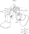
- FIG. 3 is a perspective view of the walking toy 1, in which the torso is omitted, in the same walking state as FIG. 1
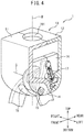
- FIG. 4 is a perspective view showing part of the torso and legs of the walking toy 1.
- FIG. 5 is a perspective view showing a right leg and right motion member, in which a lower leg part is shown by broken lines.
- the advancing direction of the walking toy 1 parallel to the walking surface on which the walking toy 1 walks will be referred to as "forward", while the direction in the opposite direction to forward will be referred to as “rearward”.
- the direction vertical to the walking surface on which the walking toy 1 walks and away from the walking surface will be referred to as “upward”, while the direction approaching the walking surface will be referred to as “downward”.
- the right direction and left direction when viewing the walking toy 1 from rearward to forward will be referred to as “rightward” and “leftward”, respectively.
- the walking toy 1 is provided with a torso 10, a pair of legs 20 connected to the torso 10, and a crank member 60.
- the walking toy 1 has two legs 20: a right leg 20a provided at the right side when viewing forward and a left leg 20b provided at the left side when viewing forward.
- the torso 10 is formed as a hollow member. As shown in FIGS. 2 and 4 , in the present embodiment, the torso 10 has a front side half 11 and a rear side half 12. These halves 11, 12 are assembled with each other whereby the torso 10 is formed. Further, the torso 10 has two side walls 13 forming the left and right side surfaces of the torso 10 (each of the side walls 13 is configured from a part of the front side half 11 and a part of the rear side half 12). The side walls 13 have recessed parts 14, at the forward bottom parts, recessed by the same extents as the thicknesses of the upper leg members 30 explained later.
- FIG. 6 is a partial cross-sectional view of a left forward bottom part of the torso 10. As shown in FIG. 6 , in the recessed part 14, a first boss 15 is formed for connecting the leg 20. At this first boss 15, a bolt hole 151 receiving a first bolt 33 is formed.
- the torso 10 is provided, inside of the side walls 13, with a pair of inside walls 16 extending in parallel to the side walls 13, that is, in the front-rear direction (see FIG. 4 ).
- the inside walls 16 are provided, one each, at the left side and right side from the center of the torso 10 in the left-right direction.
- the front side parts of the inside walls 16 are provided at the front side half 11, and the rear side parts of the inside walls 16 are provided at the rear side half 12.
- grooves 17 are formed between the front side parts and the rear side parts of the inside walls 16, grooves 17 are formed.
- the grooves 17 are formed so as to be positioned near the center of the torso 10 when viewed from the lateral direction.
- the grooves 17 are formed so as to be slightly slanted rearward in the downward direction with respect to the center axis M of the top-down direction of the torso 10. Therefore, the grooves 17 are formed so that when the torso 10 is in a state standing upright with respect to the walking surface (that is, when the center axis of the torso 10 extends in the vertical direction), the grooves 17 form an angle with respect to the walking surface (preferably, is vertical to the walking surface or forms a slight angle with respect to the vertical). Further, in the present embodiment, the grooves 17 extends straight.
- the torso 10 has a pair of rod openings 18 at its bottom wall.
- the rod openings 18 are formed adjoining the corresponding inside walls 16 at the inside from the inside walls 16 in the left-right direction.
- the openings 18 are formed so as to extend over broad ranges in the front-rear direction. Therefore, parts of the rod openings 18 are formed at the front side half 11 and the remaining parts of the rod openings 18 are formed at the rear side half 12 (see FIG. 2 ).
- a head attachment hole 191 is formed for attachment of a head member (not shown) of the walking toy 1 (see Fig. 4 ).
- arm attachment holes 192 are formed for attachment of arm members (not shown) of the walking toy 1 (see FIG. 2 ).
- These attachment holes 191, 192 are arranged between the front side half 11 and the rear side half 12.
- the head member and the arm members are connected to the torso 10 by assembling these halves 11, 12 together.
- the upper body part is configured by attaching the head member and the arm members to the torso 10. Therefore, the upper body part includes the torso 10, the head member, and the arm members.
- the head member and the arm members are formed as separate members from the torso 10, but the head member and/or the arm members may also be integrally formed with the torso 10.
- the upper body part may be formed from only the torso not including the head member and/or the arm members, and may also include a tail member or other members other than the torso 10, the head member, and the arm members.
- FIG. 7 is a schematic perspective view of a crank member 60.
- the crank member 60 is supported in the torso 10 rotatably about a rotational axis C.
- the rotational axis C of the crank member 60 extends perpendicularly to the vertical plane including the advancing direction of the walking toy 1. Further, in the present embodiment, the rotational axis C extends in parallel with a pivot axis A of the upper leg member 30.
- the crank member 60 is arranged at the center of the torso 10 in the left-right direction, and at the center of the torso 10 in the front-rear direction. Note that, the crank member 60 may be arranged at a position offset from the center of the torso 10 in the front-rear direction. Further, in the present embodiment, the crank member 60 is arranged in the cylindrically shaped space formed between the front side half 11 and the rear side half 12 of the torso 10.
- the crank member 60 has a cylindrically shaped main body 61 and a pair of crank eccentric shafts 62.
- the cylindrically shaped main body 61 is arranged in the torso 10 so that its outer circumferential surface faces the inner circumferential surface defining the cylindrically shaped space of the torso 10. Further, the cylindrically shaped main body 61 is arranged between the pair of rod openings 18 formed in the torso 10 so that the side surfaces of the main body 61face the corresponding rod openings 18.
- crank eccentric shafts 62 are respectively positioned eccentrically from the rotational axis C of the crank member 60, and project in the left-right direction from the circular side surfaces of the cylindrically shaped main body 61. Therefore, the right crank eccentric shaft 62a projects out from the right side surface of the cylindrically shaped main body 61 in the right direction, while the left crank eccentric shaft 62b projects out from the left side surface of the cylindrically shaped main body 61 in the left direction. Further, the crank eccentric shafts 62 traverse the rod openings 18 at least partially in the left-right direction, and project from the cylindrically shaped main body 61 so as to connect with the later explained motion members 50 in the rod openings 18.
- crank eccentric shafts 62 are formed so that their axes E are parallel to the rotational axis C of the crank member 60. Further, the pair of crank eccentric shafts 62 are arranged so that they are opposite phases from each other with respect to the rotational axis C of the crank member 60.
- Each of the legs 20 has an upper leg member 30, a lower leg member 40, and a motion member 50. Therefore, the right leg 20a has a right upper leg member 30a, right lower leg member 40a, and right motion member 50a, while the left leg 20b has a left upper leg members 30b, left lower leg member 40b, and left motion member 50b.
- the upper leg members 30 are members corresponding to the thighs, and are formed in elongated plate shapes.
- the top parts of the upper leg members 30 (in particular, the top end parts) are connected to the torso 10 pivotably in the front-rear direction.
- the right upper leg member 30a is connected to the bottom part of the side wall 13 at the right side of the torso 10
- the left upper leg member 30b is connected to the bottom part of the side wall 13 at the left side of the torso 10.
- each upper leg member 30 at the top part of each upper leg member 30 (in particular, the top end part), a cylindrically shaped opening 31 is formed.
- the upper leg member 30 is connected to the torso 10.
- the top part of the upper leg member 30 is connected to the torso 10 so that the upper leg member 30 can pivot in the front-rear direction with respect to the torso 10 about the axis of the first boss 15 or first bolt 33.
- the upper leg member 30 may also be connected the lower parts of the side walls of the torso 10 in any way so long as being able to pivot in the front-rear direction with respect to the torso 10 centered on the top part of the upper leg member 30.
- the lower leg members 40 are parts corresponding to the lower legs and feet, and have lower leg parts 41 corresponding to the lower legs and foot parts 42 corresponding to the feet. Therefore, the foot parts 42 are formed so as to stick out forward from the lower leg parts 41.
- the top parts of the lower leg members 40 are connected to the bottom parts of the upper leg members 30 pivotably in the front-rear direction.
- the top end parts of the lower leg members 40 are pivotably connected to the bottom end parts of the upper leg members 30 so that the connecting parts of the upper leg members 30 and lower leg members 40 appear like knee joints. Therefore, the top end part of the right lower leg member 40a is connected to the bottom end part of the right upper leg member 30a, while the top end part of the left lower leg member 40b is connected to the bottom end part of the left upper leg member 30b.
- cylindrically shaped openings 32 are formed (see FIG. 5 ).
- second bosses extending toward the outside in the left-right direction are formed.
- second bolts 34 are screwed into the bolt holes formed at the centers of the second bosses, whereby the upper leg members 30 are connected to the top parts of the lower leg members 40.
- the top parts of the lower leg members 40 are connected to the bottom parts of the upper leg members 30 so that the lower leg members 40 can pivot with respect to the upper leg members 30 in the front-rear direction about the axes of the second bolts (second bosses).
- the pivot axes B of the lower leg members 40 are parallel to the pivot axes A of the upper leg members 30.
- the lower leg members 40 may be connected to the bottom parts of the upper leg members 30 in any way as long as being able to pivot with respect to the upper leg members 30 in the front-rear direction centered on the top part.
- the foot parts 42 have contact surfaces 43 contacting the walking surface when the walking toy 1 is walking.
- the contact surfaces 43 are formed in arc shapes projecting toward the walking surface in the front-rear direction.
- the contact surfaces 43 are formed in substantially arc shapes centered on the vicinities of the top ends of the lower leg members 40, in particular the vicinities of the connecting parts of the lower leg members 40 with the upper leg members 30.
- the contact surfaces 43 may also be formed as arc shapes with single centers, or may be formed as at least two arc shapes with different centers between forward parts and rearward parts of the contact surfaces 43.
- the motion members 50 give rotational force to the crank member 60, when the torso 10 is made to move forward in the state where one leg 20 contacts the walking surface.
- the motion members 50 are formed as straight rods.
- the motion members 50 have the right motion member 50a arranged at the right side from the crank member 60, and the left motion member 50b arranged at the left side from the crank member 60.
- the motion members 50 respectively have action parts 51, torso cooperation parts 52, and eccentric shaft connecting parts 53.
- the action parts 51 are positioned at the bottom end parts of the motion members 50, while the torso cooperation parts 52 are positioned at the top end parts.
- the eccentric shaft connecting parts are positioned between the action parts 51 and the torso cooperation parts 52.
- the motion members 50 are partially arranged in the rod openings 18 formed at the torso 10.
- the action parts 51 of the motion members 50 are pivotably connected to the corresponding lower leg members 40. Therefore, the action part 51 of the right motion member 50a is pivotably connected to the right lower leg member 40a, while the action part 51 of the left motion member 50b is pivotably connected to the left lower leg member 40b. Further, the action parts 51 of the motion members 50 are connected to the corresponding lower leg members 40 at positions different from the connecting parts to the upper leg members 30. In the present embodiment, the action parts 51 of the motion members 50 are connected to the corresponding lower leg members 40 rearward from of the connecting points to the upper leg members 30.
- cylindrically shaped openings 54 are formed (see FIG. 5 ).
- third bosses extending toward the inside in the left-right direction are formed.
- third bolts 57 are screwed into the bolt holes formed at the centers of the third bosses, whereby the motion members 50 are connected to the rear parts of the top ends of the lower leg members 40.
- the action parts 51 of the motion members 50 are connected to the top rear parts of the lower leg members 40 so that the motion members 50 can pivot about the axes of the third bolts (third bosses) with respect to the lower leg members 40.
- the pivot axes D about which the motion members 50 pivot with respect to the lower leg members 40 are parallel to the pivot axes A of the upper leg members 30.
- the motion members 50 may be connected to the lower leg members 40 in any way as long as being able to pivot with respect to the lower leg members 40 centered on the action parts 51.
- the eccentric shaft connecting parts 53 of the motion members 50 are pivotably connected to the corresponding crank eccentric shafts 62. Therefore, the eccentric shaft connecting part 53 of the right motion member 50a is pivotably connected to the right crank eccentric shaft 62a, while the eccentric shaft connecting part 53 of the left motion member 50b is pivotably connected to the left crank eccentric shaft 62b.
- the eccentric shaft connecting parts 53 of the motion members 50 cylindrically shaped openings 55 are formed at the eccentric shaft connecting parts 53 of the motion members 50.
- the corresponding crank eccentric shafts 62 are fit into the openings 55. Therefore, the right crank eccentric shaft 62a is fit into the opening 55 of the right motion member 50a, while the left crank eccentric shaft 62b is fit into the opening 55 of the left motion member 50b.
- the eccentric shaft connecting parts 53 of the motion members 50 are connected to the crank eccentric shafts 62 so that the motion members 50 can pivot about the axes E of the crank eccentric shafts 62.
- cylindrically shaped projections 56 are formed at the torso cooperation parts 52 of the motion members 50.
- the projections 56 are formed so as to extend from the torso cooperation parts 52 of the motion members 50 toward the outside in the left-right direction. Therefore, the right projection 56a extends in the right direction from the torso cooperation part 52 of the right motion member 50a, while the left projection 56b extends in the left direction from the torso cooperation part 52 of the left motion member 50b.
- the projections 56 of the motion members 50 are housed in the grooves 17 so as to be able to slide in the grooves 17 formed in the inside walls 16 of the torso 10. Therefore, the projections 56 of the motion members 50 are guided along the grooves 17.
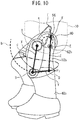
- FIGS. 8 to 11 are side views showing different walking states of the walking toy 1.
- FIGS. 8 to 11 show in order the actuating states of the walking toy 1 from the state where the left leg 20b is positioned forward most to the state where the right leg 20a is positioned forward most.
- a point A in the figures shows the position of a pivot axis A of the left upper leg member 30b with respect to the torso 10
- a point B shows the position of a pivot axis B of the left lower leg member 40b with respect to the left upper leg member 30b
- a point D shows the position of a pivot axis D of the left motion member 50b with respect to the left lower leg member 40b
- a point E shows an axis E of the left crank eccentric shaft 62b
- a point F shows an axis of the left projection 56b of the left motion member 50b.
- a line X in the figures is a line connecting the point A and the point B and shows the position of the left upper leg member 30b.
- a line Y in the figures is a line connecting the point B and the point D and shows the position of the left lower leg member 40b.
- a line Z in the figures is a line connecting the point D, the point E, and the point F and shows the position of the left motion member 50b. Note that, the point D, the point E, and the point F are on the same straight line, therefore the line Z is a straight line in the present embodiment, but the point D, the point E, and the point F are not necessarily limited to being positioned on the same straight line. Accordingly, the line Z is not necessarily limited to being a straight line.
- a broken line "b" in the figures shows a path of the point B per cycle
- a one-dot chain line “d” shows a path of the point D per cycle
- a broken line “e” shows a path of the point E per cycle
- a one-dot chain line “f' shows a path of the point F per cycle.
- the point E rotates counterclockwise (direction of arrow mark in FIG. 8 ) along the broken line "e".
- FIG. 8 shows the walking state of the walking toy 1 when the left leg 20b not contacting the walking surface is positioned forward most, that is, when the point B is positioned forward most.
- the left upper leg member 30b (line X) is positioned forward most in its range of movement
- the left crank eccentric shaft 62b is positioned substantially forward most in its range of movement
- point E is positioned substantially forward most in path "e”
- the projection 56 of the left motion member 50b point F is positioned downward in the groove 17.
- the right leg 20a contacts the ground, therefore if forward force is applied to the torso 10 from the outside, the right leg 20a receives rearward force relative to the torso 10.
- the crank member 60 receives a counterclockwise force.
- a tangential direction force acts on the left crank eccentric shaft 62b (point E).
- the projection 56 of the left motion member 50b (point F) is limited in movement in a direction perpendicular to the direction in which the groove 17 extends, in the groove 17 of the torso 10, therefore cannot move much at all in the tangential direction of the left crank eccentric shaft 62b (point E), and accordingly functions as a point of support.
- the point E acts as the point of force
- the point F acts as the point of support
- the point D acts as the point of action
- a force is applied to the point D in the direction of the arrow mark ⁇ 1 .
- force is applied to the left leg 20b in a direction lowering it. As a result, the raised left leg 20b is lowered.
- FIG. 9 shows the walking state of the walking toy 1 when the left leg 20b is lowered and the contact surface 43 (specifically, the heel part) of the left leg 20b contacts the walking surface.
- the left crank eccentric shaft 62b point E
- the projection 56 of the left motion member 50b is positioned downward in the groove 17.
- the left leg 20b contacts the ground, therefore due to the weight of the walking toy 1 and/or the downward force on the torso 10 from the outside, the left lower leg member 40b of the left leg 20b receives upward force from the walking surface. Further, if forward force is applied to the torso 10 from the outside, the left lower leg member 40b of the left leg 20b receives rearward force relative to the torso 10 from the walking surface. As a result, an upward force and rearward force are applied to the point D of the left motion member 50b (line Z).
- the projection 56 of the left motion member 50b (point F) is limited in movement in a direction perpendicular to the direction in which the groove 17 extends, in the groove 17 of the torso 10, therefore cannot move in the direction of the arrow mark ⁇ 2 and accordingly functions as a point of support.
- the point D acts as the point of force
- the point F acts as the point of support
- the point E acts as the point of action.
- a rearward oriented tangential direction force such as shown by the arrow marks ⁇ 2 in the figures is applied..
- the paths "d" of the pivot axes D of the motion members 50 of the legs 20 are generally higher when the legs 20 are not contacting the ground, than when the legs 20 are contacting the ground.
- the pivot axes D of the motion members 50 are positioned rearward of the pivot axes B corresponding to the knee joints, and the lower leg members 40 can pivot about the pivot axes B. Therefore due to the above-mentioned height difference in the path "d", when the leg 20 which had been contacting the walking surface separates from the walking surface and moves forward, the relative angle of the lower leg member 40 with respect to the upper leg member 30 changes so that the knee joint of this leg 20 bends.
- FIG. 10 shows the walking state of the walking toy when the right leg 20a not contacting the walking surface has moved forward from the left leg 20b.
- the left crank eccentric shaft 62b point E
- the projection 56 of the left motion member 50b point F
- the left motion member 50b extends substantially in the up-down direction (vertical direction).
- the left leg 20b contacts the ground, therefore the left lower leg member 40b of the left leg 20b receives upward force from the walking surface. Further, forward force from the outside is applied to the torso 10, therefore the left lower leg member 40b of the left leg 20b receives rearward force relative to the torso 10 from the walking surface.
- an upward force and rearward force are applied to the point D of the left motion member 50b (line Z).
- axial direction force of the left motion member 50b (line Z direction force) and rearward oriented tangential direction force shown by the arrow mark ⁇ 3 in the figure are applied to the point D.
- the projection 56 of the left motion member 50b is limited in motion in the direction perpendicular to the direction in which the groove 17 extends, in the groove 17 of the torso 10, therefore the projection 56 cannot move in the direction of the arrow mark ⁇ 3 , and accordingly functions as a point of support.
- the point D acts as the point of force
- the point F acts as the point of support
- the point E acts as the point of action.
- a rearward force is applied to the left crank eccentric shaft 62b (point E).
- an axial direction upward force is applied to the left motion member 50b, therefore an upward force is also applied to the left crank eccentric shaft 62b (point E).
- a rearward upward force that is, a rotational force
- the crank member 60 rotates counterclockwise.
- FIG. 11 shows the walking state of the walking toy 1 when the right leg 20a not contacting the walking surface is positioned at the forward most position. Therefore, FIG. 11 shows the state reversed left to right from the walking state shown in FIG. 8 .
- the left crank eccentric shaft 62b is positioned at substantially the rearward most place in its range of movement (point E is positioned at substantially rearward most place of path "e"), and the projection 56 of the left motion member 50b is positioned in the vicinity of the center in the groove 17.
- the left lower leg member 40b of the left leg 20b receives an upward force from the walking surface. Further, the left lower leg member 40b of the left leg 20b receives a rearward force relative to the torso 10.
- an upward force and rearward force are applied to the point E of the left motion member 50b (line Z). Therefore, force in the axial direction of the left motion member 50b (force in line Z direction) and rearward force in the tangential direction such as shown by the arrow mark ⁇ 4 in the figure are applied to the point E.
- the projection 56 (point F) of the left motion member 50b is limited in movement in a direction perpendicular to the direction in which the groove 17 extends, in the groove 17 of the torso 10, therefore the projection 56 cannot move in the direction of the arrow mark ⁇ 4 .
- the left crank eccentric shaft 62b is positioned at substantially the rearward most position in its range of movement, therefore the left crank eccentric shaft 62b (point E) does not move rearward. Therefore, even if a rearward force ⁇ 4 in the tangential direction is applied to the point D, the point D will not move rearward. Accordingly, the projection 56 functions as a point of support limiting movement of the left motion member 50b so that the point D will not move rearward further.
- the contact surface of the right leg 20a contacts the walking surface.
- an operation similar to the operation of the left leg 20b shown in FIGS. 8 to 11 is performed at the right leg 20a.
- the left leg 20b while the right leg 20a is moving rearward with respect to the torso 10, the left leg 20b not contacting the walking surface moves forward. Further, such an operation is alternately repeated at the left and right legs, whereby the walking toy 1 walks on the walking surface.
- the walking toy 1 performs walking motion, if the torso 10 is made to move forward with respect to the walking surface to make the lower leg member 40 of the one of the legs 20 contacting the walking surface move rearward relative to the torso 10.
- the projections 56 formed at the motion member 50 are guided in the grooves 17 formed in the torso 10. Therefore, the projections 56 formed at the motion members 50 and the grooves 17 of the torso 10 constitute guide mechanisms guiding the torso cooperation parts 52 of the motion members 50 with respect to the torso 10. Therefore, the projections 56 formed at the motion members 50 and the grooves 17 of the torso 10 form movement limiting mechanisms limiting the range by which the torso cooperation parts 52 of the motion members 50 can move with respect to the torso 10.
- the motion member 50 connected to this lower leg member 40 moves to apply rotational force to the crank member 60 by this motion member 50.
- the movement limiting mechanism is configured so that, when the lower leg member 40 of the one of the legs 20 contacting the walking surface moves rearward relative to the torso 10, the motion member 50 connected to this lower leg member 40 applies a rotational force to the crank member 60 by this motion member 50.
- the crank member 60 rotates, due to this rotation, the lower leg member 40 of the other leg 20 is moved forward in the state separated from the walking surface.
- the projections 56 formed at the motion members 50 and the grooves 17 of the torso 10 if the torso 10 moves forward with respect to the walking surface to make the lower leg member 40 of the one leg 20 contacting the walking surface move rearward relative to the torso 10, the one motion member 50 connected to the lower leg member 40 of the one leg 20 will pivot rearward about the torso cooperation part 52 as a point of support. Therefore, the projections 56 of the motion members 50 and the grooves 17 of the torso 10 form support point mechanisms making the torso cooperation parts 52 of the motion members 50 function as point of supports.
- the legs 20 receive an upward force from the walking surface. Further, by the user making the walking toy 1 move forward, the legs 20 receive a rearward force from the walking surface due to the frictional force. Further, due to the actions of the guide mechanisms, movement limiting mechanisms or support point mechanisms which are formed from the projections 56 of the motion members 50 and the grooves 17 of the torso 10, the upward force and rearward force applied to the legs 20 are converted to rotational force applied to the crank eccentric shafts 62.
- crank member 60 rotates. Further, by such an operation being repeatedly performed at the two left and right legs, the crank member 60 can continuously rotate and accordingly the walking toy 1 can continuously walk.
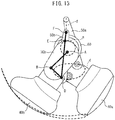
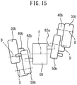
- FIGS. 12 to 13 explain the walking toy 1 according to one modification.
- FIG. 12 is a perspective view of the walking toy 1 according to the present modification where part of the torso 10 is omitted.
- FIG. 13 is a side view similar to FIG. 9 of the walking toy 1 according to the present modification.
- the walking toy 1 according to the present modification is basically configured in the same way as the walking toy 1 according to the first embodiment, therefore below, the explanation will be given centered about parts different from the walking toy 1 according to the first embodiment.
- the projections 56 of the motion members 50 are formed so as to extend from the torso cooperation parts 52 of the motion members 50 toward the inside in the left-right direction.
- the inside walls, in which the grooves 17 are formed are arranged at the insides of the corresponding motion members 50 in the left-right direction, that is, at the insides of the corresponding rod openings 18.
- the torso 10 can be formed smaller in width.
- the grooves 17 are arranged upward from the crank member 60.
- the grooves 17 extend substantially in parallel with the axial direction of the torso 10 (vertical direction) upward at the center of the crank member 60 when in a state where the torso 10 is standing upright.
- the shapes of the grooves 17 are not limited to the shapes in the above first embodiment and modification. Therefore, the grooves 17 can be made various shapes. However, the grooves 17 are preferably formed in line shapes, for example, straight line shapes, arc shapes, wave shapes, etc., so that the projections 56 of the motion members 50 move back and forth corresponding to rotation of the crank member 60. Further, the grooves 17 are preferably formed so that the torso 10 forms an angle with the walking surface when in a state where it is standing upright with respect to the walking surface. Note that, depending on the shapes of the grooves 17, the directions of the motion members 50 in the different moving states will differ, and accordingly the relationship between the positions of the projections 56 in the grooves 17 in the different moving states and the rotational phase of the crank member 60 will differ.
- the grooves 17 are formed at the torso 10, and the projections 56 guided by the grooves 17 are formed at the motion members 50.
- the torso cooperation parts 52 of the motion members 50 can be guided with respect to the torso 10
- other guide mechanisms may also be provided. Therefore, for example, grooves may be formed at the motion members 50 and projections guided by the grooves may be formed at the torso 10.
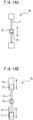
- FIGS. 14A and 14B are views schematically showing examples of the guide mechanism.
- the guide mechanism 70 shown in FIG. 14A is provided with a slide bar 71 connected to the torso 10 and a slider 72 sliding along this slide bar 71.
- a cylindrical shaped projection 73 is formed at the slider 72.
- This cylindrically shaped projection 73 fits in a cylindrically shaped opening formed in the torso cooperation part 52 of the motion member 50.
- the torso cooperation part 52 of the motion member 50 is guided along the slide bar 71 provided at the torso 10.
- the guide mechanism 75 shown in FIG. 14B is provided with two cylinders 76 formed at the torso 10 and having the same axes, two pistons 77 sliding in these two cylinders 76, and a connecting member 78 connecting these pistons 77.
- the connecting member 78 moves along the axes of the cylinders 76.
- a cylindrically shaped projection 79 is formed at the connecting member 78. This cylindrically shaped projection 79 fits in a cylindrically shaped opening formed in the torso cooperation part 52 of the motion member 50.
- the torso cooperation part 52 of motion member 50 is guided along the axes of the cylinders 76 provided at the torso 10.
- the torso cooperation part 52 of the motion member 50 can function as a point of support, instead of the groove 17 and the projection 56 or instead of the above guide mechanism, another support point mechanism may be provided.
- another support point mechanism may also be provided.
- Such support point mechanism or the movement limiting mechanism includes, for example, a simple structure mechanical link mechanism, etc. Specifically, it may be considered that one end part of a link member with the other end part pivotably connected to the torso 10 is pivotably connected to the torso cooperation part 52 of the motion member 50.
- the pivot axis A of the upper leg member 30 with respect to the torso 10 are parallel with the rotational axis C of the crank member 60.
- the pivot axis A of the upper leg member 30, the pivot axis B of the lower leg member 40, and the pivot axis D of the motion member 50 may have angles with respect to the rotational axis C of the crank member 60.
- the rotational axis C of the crank member 60 extends perpendicular to the vertical surface including the advancing direction.
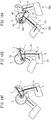
- FIGS. 16 to 18A to 18C a walking toy 1 according to a second embodiment will be explained. Below, the explanation will be given focused on parts different from the walking toy according to the first embodiment.
- FIG. 16 is a cross-sectional side view of the walking toy 1 according to the second embodiment
- FIG. 17 is a perspective view of the walking toy 1 in which part of the torso 10 is omitted
- FIGS. 18A to 18C are side view of the walking toy 1 in which the torso 10 is omitted.
- the walking toy 1 of the present embodiment is provided, similarly to the walking toy in the first embodiment, with a torso 10, a pair of legs 20, and a crank member 60.
- the torso 10 has a bottom side half 11' and a top side half 12'. These halves 11', 12' are assembled with each other whereby the torso is formed.
- the grooves 17 are formed between these bottom side half 11' and top side half 12'.
- a pair of grooves 17 of the same shapes are provided at the both sides of the legs 20.
- the legs 20 do not have the upper leg members and lower leg members, and have only motion members 50.
- the motion members 50 according to the present embodiment are provided with connecting parts 58 and extension parts 59 extending from the connecting parts 58 to the outside.
- the motion members 50 are configured so that the connecting parts 58 and the extension parts 59 has substantially a T-shape.
- the connecting parts 58 have torso cooperation parts 52 at one of the end parts thereof and have eccentric shaft connecting parts 53 at the other of the end parts thereof.
- the extension parts 59 have action parts 51 at their front end parts. Therefore, the motion members 50 are respectively provided with action parts 51, torso cooperation parts 52, and eccentric shaft connecting parts 53.
- foot parts 591 corresponding to feet are provided at the front ends of the extension parts 59.
- the foot parts 591 have contact surfaces which contact the walking surface when the walking toy 1 is walking in the same way as the foot parts of the first embodiment. Therefore, the action parts 51 positioned at the front end parts of the extension parts 59 contact the walking surface when the legs 20 having the action parts 51 contact the walking surface.
- the eccentric shaft connecting parts 53 of the motion members 50 are pivotably connected to the corresponding crank eccentric shafts 62. Therefore, the eccentric shaft connecting parts 53 are connected to the crank eccentric shafts 62 so that the motion members 50 can pivot about the axes of the crank eccentric shafts 62.
- the torso cooperation parts 52 of the motion members 50 columnar shaped parts are formed.
- the two ends of the columnar shaped parts constitute projections 56 projecting to the left-right direction from the connecting parts 58. Therefore, in the present embodiment, the torso cooperation parts 52 have two projections 56 projecting out in opposite directions from each other. These projections 56 are housed in the grooves 17 formed in the torso 10 so that they slide in the grooves 17.
- the thus configured walking toy 1 according to the second embodiment also walks by the legs 20 by the user pushing, by hand, etc., the torso 10 forward to make the torso 10 move forward in the state with the contact surface of at least one of the legs 20 contacting the walking surface.
- FIGS. 18A to 18C show different walking states of the walking toy 1. Note that, in FIGS. 18A to 18C as well, the point D is shown for convenience in the same way as FIGS. 9 to 11 , but in the present embodiment, the point D does not function as a pivot axis.
- FIG. 18A shows the walking state of the walking toy 1 when the left motion member 50b of the left leg 20b, which was not contacting the ground, contacts the ground. At this time, an upward force and rearward force are applied to the action part 51 of the left motion member 50b. Further, the projection 56 (point F) of the left motion member 50b functions as a point of support, therefore a rotational force is applied to the left crank eccentric shaft 62b (point E) and thus the crank member 60 rotates counterclockwise.
- FIG. 18B shows the walking state of the walking toy 1 when the right motion member 50a of the right leg 20a not contacting the walking surface moves forward from the left motion member 50b of the left leg 20b contacting the walking surface.
- FIG. 18C shows the walking state of the walking toy 1 when the right motion member 50a of the right leg 20a, which did not contact the walking surface, contacts the walking surface.
- an upward force and rearward force are applied from the walking surface to the action part 51 of the left motion member 50b.
- the projection 56 of the left motion member 50b (point F) functioning as a point of support, a rotational force is applied to the left crank eccentric shaft 62b (point E) and thus the crank member 60 rotates counterclockwise.
- the walking toy 1 can be made to continuously walk. Therefore, according to the present embodiment, using the guide mechanisms, movement limiting mechanisms, or support point mechanisms which is formed from the projections 56 of the motion members 50 and the grooves 17 of the torso 10, that is, using simple mechanisms, it is possible to make the crank member 60 stably rotate and accordingly possible to make the walking toy 1 stably walk by a fewer number of parts than the first embodiment.
- the motion members 50 are formed so as to have T-shapes, but they may also be formed so as to have shapes different from T-shapes. Therefore, for example, the motion members 50 may be formed in straight shapes in similarly to the first embodiment. Further, conversely, the motion members according to the first embodiment may be formed in T-shapes similarly to the motion members according to the second embodiment.
- FIGS. 19 to 20 a walking toy 1 according to a third embodiment will be explained. Below, the explanation will be given focused on parts different from the walking toy according to the first embodiment.
- FIG. 19 is a side view schematically showing the walking toy 1 according to the third embodiment.
- the walking toy 1 according to the present embodiment is provided with a walking aid 80 attached to the torso 10, in addition to the walking toy according to the first embodiment or the second embodiment provided with the torso 10, legs 20, and crank member 60 (below, also referred to as the "doll part").
- the walking aid 80 aids the walking motion by the doll part of the walking toy 1.
- the walking aid 80 is provided with a main body part 81, an arm 82 fixed to the main body part 81 and to be attached to the torso 10, and wheels 83 continuously in contact with the walking surface.
- the main body part 81 is formed as a hollow housing. In the example shown in FIG. 19 , the main body part 81 has a box shape, but it may have any shape. At the top surface of the main body part 81, a switch 85 for operating a locking part provided at the arm 82, is provided. Note that, as long as being possible to operate the locking part, the switch 85 may be arranged anywhere at the walking aid 80.
- the arm 82 is formed in a hollow shape. At the bottom end part, it is fixed to the front of the main body part 81. Further, the arm 82 is attached to the rear side of the torso 10 at its top end part. In the present embodiment, the attachment position of the arm 82 to the torso 10 is higher than the position fixed to the main body part 81. Therefore, the arm 82 is attached to the torso 10 so as to be slanted upward toward the front, that is, so as to be slanted upward from the position fixed to the main body part 81 toward the position attached to the torso 10.
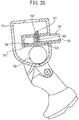
- FIG. 20 is a schematic cross-sectional view of the vicinity of the torso 10 showing the state where the top end part of the arm 82 is attached to the torso 10.
- an attachment part 821 to be attached to a receiving part 101 of the torso 10 is formed.
- the attachment part 821 is, for example, a bar part formed into an angular columnar shape.
- the receiving part 101 to which the attachment part 821 is attached is, for example, formed at the rear surface of the torso 10 as a receiving hole having a shape complementary to the bar part having an angular columnar shape. Therefore, in the present embodiment, the attachment part 821 is attached to the receiving part 101 by the bar part of the attachment part 821 being inserted into the receiving hole of the receiving part 101.
- a sliding opening 86 is formed at the top part of the attachment part 821. Inside this sliding opening 86, a locking part 87 sliding along the sliding opening 86 is arranged. In the present embodiment, the sliding opening 86 is formed at the top surface of the attachment part 821.
- the locking part 87 can slide between a projecting state where it projects upward from the sliding opening 86 of the attachment part 821 and a stored state where it is stored in the sliding opening 86.
- the locking part 87 is biased upward by an elastic member 88. Therefore, the locking part 87 is maintained in the projecting state when force is not applied from the outside.
- a locking hole 102 is formed at a position facing the sliding opening 86 when the attachment part 821 is attached to the receiving part 101. Therefore, when the attachment part 821 is attached to the receiving part 101 and the locking part 87 is in the projecting state, the locking part 87 is locked in the locking hole 102 and accordingly the attachment part 821 is locked in the receiving part 101.
- a strap 89 is provided at the bottom surface of the locking part 87.
- This strap 89 is passed through the inside of the hollow arm 82 and connected to the switch 85.
- the switch 85 when the switch 85 is operated by the user, the locking part 87 slides against the biasing force of the elastic member 88 from the projecting state to the stored state.
- the switch when the switch is operated, the lock of the locking part 87 in the locking hole 102 is released and, accordingly, the lock of the attachment part 821 in the receiving part 101 is released.
- the wheels 83 continuously contact the walking surface at positions different from the legs 20 while walking motion by the legs 20 is being performed.
- the walking aid 80 is provided with only one set of wheels rotatably attached to the main body part 81.
- these wheels rotate about one axis G substantially perpendicular to the front-rear direction.
- the walking aid 80 is formed so that when attached to the torso 10, the torso 10 is held at a specific angle with respect to the walking surface.
- the walking aid 80 is formed so that the torso 10 is held in a state standing upright with respect to the walking surface (that is, a state in which the axis of the torso 10 extends in the vertical direction).
- the thus configured walking aid 80 constantly contacts the walking surface by the wheels 83.
- the doll part usually only one leg contacts the walking surface during walking. In this case, sometimes stumbling will occur due to staggering tilting to the front, rear, left, or right direction.
- frictional force must be generated between the leg contacting the walking surface and the walking surface, but if staggering occurs such as described above, there is a possibility that the frictional force will be insufficient.
- the wheels 83 are constantly in contact with the ground, therefore such staggering can be kept from occurring.
- wheels 83 are used as auxiliary contact parts continuously contacting the walking surface.
- auxiliary contact parts other than the wheels 83 may also be used.
- Such auxiliary contact parts may also be flat shaped contact members. Alternatively, they may be the walking toy according to the first embodiment or the second embodiment provided with the torso, legs, and crank member.
- the walking aid 80 is attached to the rear side of the torso 10.
- the walking aid 80 may also be attached to a portion different from the rear side of the torso 10. For example, it may be attached to the front side of the torso 10.
- the arm 82 slants upward from the position fixed to the main body part 81 to the position attached to the torso 10. Therefore, due to the gravitational force applied to the arm 82, the arm 82 is acted on by a moment centered on the wheels 83 of the main body part 81. Further, if a forward downward force ⁇ 1 is applied to the arm 82 from the outside, due to that force as well, the arm 82 is acted on by a moment centered on the wheels 83 of the main body part 81. As a result, at the position of attachment of the arm 82 to the torso 10, a forward downward force ⁇ is applied to the torso 10.
- the walking aid 80 is attached to the torso 10 so that a forward and downward force are applied to the torso 10 when a forward and downward force is applied to the walking aid 80.
- the torso 10 moves forward due to application of the forward force ⁇ to the arm 82, the frictional force generated between the contact surface of the leg 20 contacting the walking surface and the walking surface becomes larger. For this reason, the leg 20 is kept from sliding on the walking surface in a forward orientation when forward force is applied to the torso 10.
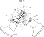
- FIG. 21 is a side view showing the walking state of the walking toy 1 when the torso 10 is in a state slanted to a forward orientation.
- the left leg 20b and the left lower leg member 40b are positioned at the forward most position (position lifted up the most). Further, in this state, the left leg 20b, which had up to then moved forward without contacting the walking surface, contacts the walking surface. Therefore, if tilting the torso 10 with respect to the walking surface further to the forward orientation, the left leg 20b which had been moving forward without contacting the walking surface contacts the walking surface before reaching the forward most position.
- the walking toy 1 cannot continuously perform walking motion.
- the angle of the torso 10 with respect to the walking surface is an angle in a certain range larger than the angle shown in FIG. 21 (right angle side)
- the lower leg members 40 of the legs 20 which moved forward in the state separated from the walking surface, contact the walking surface after reaching the forward most positions. Therefore, in this case, the walking toy 1 can continuously perform walking motion.
- the walking toy 1 may reach a state where the contact surfaces of the lower leg members 40 extend substantially vertical. If reaching such a state, even if making the torso 10 move forward, a rearward force can no longer be applied to the lower leg members 40. As a result, the walking toy 1 can no longer continuously perform walking motion. Therefore, even if the torso 10 slants too much in the rearward orientation, the walking toy 1 cannot continuously perform walking motion. Therefore, in the walking toy 1, walking motion is continuously performed if the angle of the axis of the torso 10 with respect to the walking surface is within a certain range.
- the walking aid 80 holds the torso 10 of the doll part so that the angle of the axis of the torso 10 with respect to the walking surface is substantially a right angle. Therefore, the angle of the axis of the torso 10 with respect to the walking surface is an angle within the above-mentioned certain range. For this reason, the walking toy 1 having the walking aid 80 according to the present embodiment can continuously perform walking motion.
- the walking aid 80 may hold the torso 10 so that the axis of the torso 10 has an angle with respect to the walking surface different from a right angle if the angle of the axis of the torso 10 with respect to the walking surface is maintained in the above-mentioned certain range.
- the walking aid 80 may also be configured so as to enable change of the angle of the axis of the torso 10 with respect to the walking surface in the above-mentioned certain range.
- the arm 82 is attached to the torso 10, but it may also be attached to a member of the upper body part different from the torso 10, for example, the head member or the arm members. Further, in the present embodiment, the arm 82 and main body part 81 of the walking aid 80 are configured as members separate from the torso 10. However, the walking aid 80 may also be formed integrally with the torso 10. In this case, the walking aid 80 cannot be detached from the torso 10.
- the walking toy As the doll part of the walking toy 1, the walking toy according to the above first embodiment is used. However, as the doll part, a doll part of a configuration different from the walking toy according to the above first embodiment may be used. However, even in this case, the doll part is configured so that if the angle of the torso with respect to the walking surface in the front-rear direction is within a certain range, the walking motion is continuously performed. Alternatively, the doll part is configured so that if the angle of the axis of the torso with respect to the walking surface in the front-rear direction is within a constant range, the lower leg member 40 of the leg 20 which had been moved forward in the state separated from the walking surface reaches the forward most position, then contacts the surface.
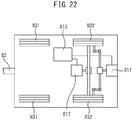
- FIG. 22 is a schematic plan view of a main body part 81 of a walking aid 80 according to a modification of the third embodiment.
- the walking aid 80 according to the present modification has four wheels 83.
- the two front side walls are driven wheels 831, while the two rear side wheels are steering drive wheels 832.
- the main body part 81 has a steering motor 811, drive motor 812, and electronic control unit 813 connected to these motors 811, 812.
- the steering drive wheels 832 are steered by the steering motor 811 and are driven by the drive motor 812.
- the steering motor 811 and the drive motor 812 are controlled by the electronic control unit 813.
- the electronic control unit 813 may also be provided with a communication device enabling communication with an outside controller.
- the steering motor 811 and the drive motor 812 are controlled by the outside controller.
- the walking aid 80 may also not have driven wheels 831 and have only steering drive wheels 832.
- the steering motor 811 may not be provided either. Accordingly, the steering drive wheels 832 may not be steered.
- the walking aid 80 being provided with motors driving the wheels 83, the walking toy can be made to walk even without the user pushing the torso 10 by his hands.
- FIGS. 23 to 25B a walking toy 1 according to a fourth embodiment will be explained. Below, the explanation will be given centered on parts different from the walking toy according to the third embodiment.
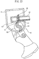
- FIG. 23 is a schematic side view of the vicinity of the torso 10, similar to FIG. 16 .
- the walking toy 1 according to the present embodiment is provided with a phase detector 90 detecting a rotational phase of the crank member 60.
- the phase detector 90 is provided with a detected part 64 formed at the crank member 60 and a detector 91 arranged so as to face the detected part 64.
- the output signal of the phase detector 90 is input to a computer (not shown) arranged in the walking toy 1.
- the output signal of the phase detector 90 may be input through a communicating means to an outside computer.
- These computers perform processing according to the signal input from the phase detector 90. They are used for processing inside.
- the detected rotational phase is, for example, used for operating other equipment linked with motion of the legs 20 of the walking toy 1.
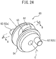
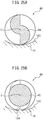
- FIG. 24 is a perspective view of a crank member 60 according to the present embodiment. Further, FIG. 25A is a cross-sectional view of the crank member 60 seen along A-A of FIG. 24 , while FIG. 25B is a cross-sectional view of the crank member 60 seen along B-B of FIG. 24 . In FIGS. 25A and 25B , part of the torso 10 is shown in addition to the crank member 60.
- the crank member 60 is provided with a pair of disk shaped members 63 arranged at the outsides in the direction of the rotational axis C, and the detected part 64 and spacer 65 provided between the disk shaped members 63.
- the spacer 65 is arranged adjoining the detected part 64.
- the detected part 64 is formed by two members with semicircular shaped cross-sections combined with each other eccentrically with respect to the rotational axis C of the crank member 60. Therefore, the detected part 64 is formed so that its outer circumferential surface changes in distance from the rotational axis C in the circumferential direction of the crank member 60.
- the spacer 65 is formed in a columnar shape so that its outside diameter is smaller than the maximum outside diameter of the detected part 64. Therefore, the spacer 65 has an outer circumferential shape different from the detected part 64.
- a projecting part 104 is provided on the wall surface 103 of the torso 10 facing the spacer 65.
- This projecting part 104 has a height so as to not reach the outer circumferential surface of the spacer 65. Further, the projecting part 104 has a height so that when the crank member 60 is arranged in the opposite direction vis-a-vis the left and right in the torso 10 and the projecting part 104 faces the detected part 64 of the crank member 60, the projecting part 104 will contact the detected part 64 during rotation of the crank member 60.
- the torso 10 is formed so that when the crank member 60 is arranged in the torso 10 in the first direction (correct direction), the torso 10 will not interfere with the outer circumferential surface of either of the detected part 64 and spacer 65 and so that when the crank member 60 is arranged in the torso 10 in the second direction opposite to the first direction (mistaken direction), the torso 10 will interfere with the outer circumferential surface of the detected part 64. As a result, it is possible to prevent the crank member 60 from being arranged in the opposite direction.
- the spacer 65 may be formed so that its outside diameter is larger than the maximum outside diameter of the detected part 64.
- the torso 10 when the crank member 60 is arranged in the torso 10 in the first direction, the torso 10 will not interfere with the outer circumferential surface of either of the detected part 64 and spacer 65, and when the crank member 60 is arranged in the torso in the second direction opposite to the first direction, the torso 10 will interfere with the outer circumferential surface of the spacer 65.
- the detector 91 is arranged at the attachment part 821 of the arm 82. Further, the receiving part 101 is positioned upward from the crank member 60. Therefore, the attachment part 821 is positioned upward from the detected part 64 when attached to the receiving part 101. Further, the detector 91 is arranged at the bottom side of the attachment part 821. Therefore, the detector 91 is arranged at the attachment part 821 so as to face the top surface of the detected part 64 of the crank member 60 when the attachment part 821 is attached to the receiving part 101.
- the detector 91 is an optical sensor detecting a distance to an object facing the detector 91.
- the detector 91 is arranged so as to face the detected part 64, therefore outputs a signal corresponding to the distance to the outer circumferential surface of the detected part 64.
- the attachment part 821 is provided with a locking part 87 at its top side.
- the attachment part 821 can be provided with both the locking part 87 and detector 91.
- the detector 91 faces the top surface of the detected part 64 in the torso 10. Therefore, since the detector 91, which is an optical sensor, detects distance in a relatively dark in of the torso 10, it can detect the distance with a high precision.
- the detector 91 is arranged at the bottom side of the attachment part 821.
- the attachment part 821 can be inserted up to the deep end in the torso 10. As a result, the attachment part 821 can be stably attached to the receiving part 101.
- the detector 91 may be a magnetic sensor, contact type sensor, or other sensor. Further, so long as able to detect a phase of the crank member 60, the phase detector 90 may also be configured as a rotary pulse detection sensor outputting a pulse signal each time the crank member 60 rotates by a certain angle, or other phase detector.
- the detector 91 is provided at the attachment part 821 of the walking aid 80.
- the detector 91 may, for example, also be arranged in the torso 10, or may also be provided at a part separate from the walking aid 80.
- the front side of the torso 10 may be provided with a receiving part different from the receiving part 101 and an attachment part having a detector may be attached to that receiving part.
- the attachment member may have a communication device able to send output from the detector to an outside device.
- the projecting part 104 is provided on the wall surface 103 of the torso 10 at a position facing the spacer 65.
- the projecting part 104 may also be provided on the wall surface 103 at a position facing the detected part 64.
- the spacer 65 has to have a maximum outside diameter larger than the maximum outside diameter of the detected part 64.
Landscapes
- Toys (AREA)
- Manipulator (AREA)
Abstract
Description
- The present disclosure relates to a walking toy.
- A walking toy having a torso and two legs connected to the torso and walking by the legs when making the torso move forward in the state with the bottom end surface of at least one leg contacting the ground, floor, or other walking surface, has been studied (for example,
WO2017/212899 ). In such a walking toy, when making the torso move forward to move the one leg contacting the walking surface relatively rearward, a crank member rotates and, due to the rotation of the crank member, the other leg is moved forward in the state separated from the walking surface. By such an operation being continuously performed, the walking toy walks by its legs. - In this regard, in one aspect, in one mechanism of the walking toy described in
WO2017/212899 , a large number of links are provided, therefore the structure thereof is complicated and the number of parts thereof is large. Further, in another aspect, in another mechanism of the walking toy described inWO2017/212899 , when making one leg move relatively rearward, sometimes the crank member has difficulty in rotating along with the movement, and accordingly there is a possibility of stable walking of the walking toy sometimes being difficult to be kept continuing. In this way, there is room for improvement of the walking mechanism of the walking toy described inWO2017/212899 . - In consideration of the above technical issue, an object of the present disclosure is to provide a walking toy having a walking mechanism different from a conventional walking toy.
- The gist of the present disclosure is as follows:
- (1) A walking toy having: an upper body part including a torso; and two legs connected to the torso, in which if the torso is made to move forward in the state where a contact surface of at least one leg contacts a walking surface, walking motion is performed by the legs, the walking toy comprising:
- a crank member rotatably supported in the torso and having a pair of crank eccentric shafts positioned eccentrically from a rotational axis of the crank member, wherein
- the crank eccentric shafts are arranged so as to have opposite phases from each other with respect to the rotational axis,
- each of the legs has a motion member giving rotational force to the crank member when the torso moves forward,
- each of the motion members has an eccentric shaft connecting part pivotably connected to the corresponding crank eccentric shaft, a torso cooperation part cooperating with the torso, and an action part on which force received from the walking surface act,
- grooves are formed at one of the torso cooperation parts of the motion members and the torso, and projections sliding in the grooves and guided by the grooves are formed at the other of the torso cooperation parts and the torso,
- the grooves are configured so that the projections can reciprocate in the grooves corresponding to rotational motion of the crank member, and
- if the torso is made to move forward to make the action part of the motion member of the one leg contacting the walking surface move rearward relative to the torso, the motion member of the one leg moves to thereby impart rotational force to the crank member by the motion member due to the projection being limited in movement in the groove and, the other leg is made to move forward in the state separated from the walking surface due to rotation of the crank member and then is made to contact the walking surface.
- (2) A walking toy having: an upper body part including a torso: and two legs connected to the torso, in which if the torso is made to move forward in the state where a contact surface of at least one leg contacts a walking surface, walking motion is performed by the legs, the walking toy comprising:
- a crank member rotatably supported in the torso and having a pair of crank eccentric shafts positioned eccentrically from a rotational axis of the crank member, wherein
- the crank eccentric shafts are arranged so as to have opposite phases from each other with respect to the rotational axis,
- each of the legs has a motion member giving rotational force to the crank member when the torso moves forward,
- each of the motion members has an eccentric shaft connecting parts pivotably connected to the corresponding crank eccentric shafts, a torso cooperation parts cooperating with the torso, and an action part on which force received from the walking surface act,
- support point mechanisms making the torso cooperation parts of the motion members function as points of support in the motion members are formed at the torso cooperation parts of the motion members and the torso, and
- if the torso is made to move forward to make the action part of the motion member of the one leg contacting the walking surface move rearward relative to the torso, the motion member of the one leg is pivoted using the upper part of that motion member as a point of support, and a rotational force is applied to the crank member by the motion member of the pivoting one leg and, the other leg is made to move forward in the state separated from the walking surface due to rotation of the crank member and then is made to contact the walking surface.
- (3) The walking toy according to the above (2), wherein the support point mechanisms include guide mechanisms guiding the torso cooperation parts of the motion members with respect to the torso.
- (4) A walking toy having: an upper body part including a torso: and two legs connected to the torso, in which if the torso is made to move forward in the state where a contact surface of at least one leg contacts a walking surface, walking motion is performed by the legs, the walking toy comprising:
- a crank member rotatably supported in the torso and having a pair of crank eccentric shafts positioned eccentrically from a rotational axis of the crank member, wherein
- the crank eccentric shafts are arranged so as to have opposite phases from each other with respect to the rotational axis,
- each of the legs has a motion member giving rotational force to the crank member when the torso moves forward,
- each of the motion members has an eccentric shaft connecting part pivotably connected to the corresponding crank eccentric shafts, a torso cooperation parts cooperating with the torso, and an action part on which force received from the walking surface act,
- movement limiting mechanisms limiting the range by which the torso cooperation parts of the motion members can move with respect to the torso are formed at the torso cooperation parts of the motion members and the torso, and
- if the torso is made to move forward to make the action part of the motion member of the one leg contacting the walking surface move rearward relative to the torso, the motion member of the one leg moves to apply rotational force to the crank member by the motion member due to the range of possible movement of the torso cooperation part being limited by the movement limiting mechanism, and, the other leg is made to move forward in a state separated from the walking surface due to rotation of the crank member and then contacts the walking surface.
- (5) The walking toy according to the above (4), wherein the movement limiting mechanisms include guide mechanisms guiding the torso cooperation parts with respect to the torso.
- (6) The walking toy according to the above (3) or (5), wherein the guide mechanisms guide the torso cooperation parts with respect to the torso in a direction where the torso forms an angle with respect to the walking surface when the torso is in a state standing upright with respect to the walking surface.
- (7) The walking toy according to any one of the above (3), (5), and (6), wherein
the guide mechanisms have grooves provided at one of the torso cooperation parts and the torso, and projections provided at the other of the torso cooperation parts and the torso, and
the projections slide in the grooves whereby the torso cooperation parts are guided with respect to the torso. - (8) The walking toy according to any one of the above (1) to (7), wherein the action parts of the motion members contact the walking surface when the legs having the motion members contact the walking surface.
- (9) The walking toy according to any one of the above (1) to (7), wherein each of the legs further has an upper leg member and a lower leg member,
the upper part of the upper leg member is pivotably connected to the torso and the lower leg member is pivotably connected to a lower part of the upper leg member, and
the action part of each of the motion members is connected to the corresponding lower leg member at a position different from the connecting part to the upper leg members. - (10) The walking toy according to the above (9), wherein the action part of each of the motion members is pivotably connected to the corresponding lower leg member at a positions rearward from the connecting part to the upper leg members.
- (11) The walking toy according to any one of the above (1) to (10), wherein the motion members are straight rods, and
the eccentric shaft connecting part is positioned between the torso cooperation part and the action part. - (12) The walking toy according to any one of the above (1) to (11), wherein the contact surface of each of the legs is formed in an arc shape sticking out toward the walking surface in the front-rear direction.
- (13) The walking toy according to any one of the above (1) to (12), wherein the walking toy further comprises a walking aid attached to the upper body part, and
the walking aid has an auxiliary contact part continuously contacting the walking surface at a position different from the legs while the walking motion is being performed. - (14) The walking toy according to the above (13), wherein the auxiliary contact parts are wheels.
- (15) The walking toy according to the above (14), wherein the wheels rotate about a single axis substantially perpendicular to the front-rear direction.
- (16) The walking toy according to the above (14) or (15), wherein the walking aid has a motor driving the wheels.
- (17) The walking toy according to any one of the above (13) to (16), wherein the walking aid is attached to the rear side of the upper body part.
- (18) The walking toy according to any one of the above (13) to (17), wherein the walking aid is attached to the upper body part so that a forward and downward force are applied to the upper body part when a forward and downward force are applied to the walking aid.
- (19) The walking toy according to the above (18), wherein the walking aid has a main body part having auxiliary contact parts, and an arm fixed to the main body part at one of the end parts and attached to the rear side of the upper body part at the other end part, and the arm is attached to the upper body part so as to be slanted upward from a position fixed to the main body part toward a position attached to the upper body part.
- (20) The walking toy according to any one of the above (13) to (19), wherein
the torso, the legs, and the crank member are configured so that the walking motion is continuously performed when the angle, in the front-rear direction, of the axis of the torso with respect to the walking surface is within a certain range, and
the walking aid holds the torso so that the angle of the axis of the torso with respect to the walking surface is maintained within the certain range. - (21) The walking toy according to any one of the above (13) to (19), wherein
the torso, the legs, and the crank member are configured so that the lower leg member of the other leg which had been moved forward in a state separated from the walking surface contacts the ground after reaching the forward most position, if the angle, in the front-rear direction, of the axis of the torso with respect to the walking surface is within a certain range, and
the walking aid holds the torso so that the angle of the axis of the torso with respect to the walking surface is maintained within the certain range. - (22) The walking toy according to any one of the above (13) to (21), wherein the walking aid has an attachment part and the upper body part has a receiving part, and
the walking aid is detachably attached with respect to the upper body part by the attachment part being detachably attached with respect to the receiving part. - (23) The walking toy according to any one of the above (1) to (22), further comprising a phase detector detecting a rotational phase of the crank member.
- (24) The walking toy according to the above (23), wherein
the phase detector has a detected part provided at the crank member, and a detector arranged so as to face the detected part,
the detected part is formed so that an outer circumferential surface thereof changes in distance from the rotational axis of the crank member in the circumferential direction of the crank member,
the detector outputs a signal corresponding to the distance to the outer circumferential surface of the detected part. - (25) The walking toy according to the above (22), further comprising a phase detector detecting a rotational phase of the crank member, wherein
the phase detector has a detected part provided at the crank member and a detector arranged at the attachment part so as to face the detected part,
the detected part is formed so that an outer circumferential surface thereof changes in distance from the rotational axis of the crank member in the circumferential direction of the crank member, and
the detector outputs a signal corresponding to the distance to the outer circumferential surface of the detected part. - (26) The walking toy according to the above (25), wherein the detector is an optical sensor detecting a distance to an object,
the receiving part is a receiving hole formed in the torso,
the attachment part is configured so as to be inserted in the receiving hole, and
the detector is arranged at the attachment part so that the detector faces the detected part in the torso when the attachment part is inserted into the receiving part. - (27) The walking toy according to the above (25) or (26), wherein
the attachment part is positioned upward from the detected part when attached to the receiving part, and
the detector is arranged at the bottom side of the attachment part so as to face the top surface of the detected part when the attachment part is attached to the receiving part. - (28) The walking toy according to any one of the above (24) to (27), wherein
the crank member has a spacer arranged in a rotational axis direction of the detected part and the spacer has an outer circumferential shape different from the detected part, and
the torso is formed so that the torso does not interfere with either outer circumferential surface of the detected part or the spacer when the crank member is arranged in the torso in a first direction, and so that the torso interferes with either outer circumferential surface of the detected part or the spacer when the crank member is arranged in the torso in a second direction opposite to the first direction. - (29) The walking toy according to any one of the above (23) to (28), further comprising a computer to which a signal output from the phase detector is input and performing processing according to the input signal.
- According to the present disclosure, a walking toy having a walking mechanism different from a conventional walking toy is provided.
-
-
FIG. 1 is a front view of a walking toy. -
FIG. 2 is a side view of the walking toy in the same walking state asFIG. 1 . -
FIG. 3 is a perspective view of the walking toy in which a torso is omitted, in the same walking state asFIG. 1 . -
FIG. 4 is a perspective view showing part of the torso and legs of the walking toy. -
FIG. 5 is a perspective view showing a right leg and a right motion member. -
FIG. 6 is a partial cross-sectional view of a left forward bottom part of the torso. -
FIG. 7 is a schematic perspective view of a crank member. -
FIG. 8 shows a walking state of the walking toy when a left leg not contacting the walking surface is positioned at a forward most place. -
FIG. 9 shows a walking state of the walking toy when the left leg is lowered and a contact surface of the left leg contacts the walking surface. -
FIG. 10 shows a walking state of the walking toy when a right leg not contacting the walking surface has moved forward from the left leg. -
FIG. 11 shows a walking state of the walking toy when the right leg not contacting the walking surface is positioned at a forward most place. -
FIG. 12 is a perspective view of a walking toy according to a modification of the first embodiment. -
FIG. 13 is a side view similar toFIG. 9 of the walking toy according to a modification of the first embodiment. -
FIGS. 14A and 14B are views schematically showing an example of a guide mechanism. -
FIG. 15 is a schematic top view of the walking toy in which the torso is omitted. -
FIG. 16 is a cross-sectional side view of a walking toy according to a second embodiment. -
FIG. 17 is a perspective view of the walking toy in which part of the torso is omitted. -
FIGS. 18A to 18C are side views of the walking toy in which the torso is omitted. -
FIG. 19 is a side view schematically showing a walking toy according to a third embodiment. -
FIG. 20 is a schematic cross-sectional view of the vicinity of the torso, showing the state where an upper end part of the arm is attached to the torso. -
FIG. 21 is a side view showing a walking state of the walking toy, in the state where the torso is slanted in a forward orientation. -
FIG. 22 is a schematic plan view of a main body part of a walking aid according to a modification of the third embodiment. -
FIG. 23 is a schematic side view of the vicinity of the torso similar toFIG. 20 . -
FIG. 24 is a perspective view of a crank member according to a fourth embodiment. -
FIGS. 25A and 25B are cross-sectional views of the crank member. - Below, embodiments will be explained in detail while referring to the drawings. In the following explanation, similar component elements are assigned the same reference notations.
- First, referring to
FIGS. 1 to 4 , a walking toy 1 according to a first embodiment will be explained.FIG. 1 is a front view of the walking toy 1,FIG. 2 is a side view of the walking toy 1 in the same walking state asFIG. 1 , andFIG. 3 is a perspective view of the walking toy 1, in which the torso is omitted, in the same walking state asFIG. 1 . Further,FIG. 4 is a perspective view showing part of the torso and legs of the walking toy 1.FIG. 5 is a perspective view showing a right leg and right motion member, in which a lower leg part is shown by broken lines. - In this Description, the advancing direction of the walking toy 1 parallel to the walking surface on which the walking toy 1 walks will be referred to as "forward", while the direction in the opposite direction to forward will be referred to as "rearward". Further, the direction vertical to the walking surface on which the walking toy 1 walks and away from the walking surface will be referred to as "upward", while the direction approaching the walking surface will be referred to as "downward". In addition, the right direction and left direction when viewing the walking toy 1 from rearward to forward will be referred to as "rightward" and "leftward", respectively.
- As shown in
FIGS. 1 to 5 , the walking toy 1 is provided with atorso 10, a pair oflegs 20 connected to thetorso 10, and acrank member 60. In particular, in the present embodiment, the walking toy 1 has two legs 20: aright leg 20a provided at the right side when viewing forward and aleft leg 20b provided at the left side when viewing forward. - The
torso 10 is formed as a hollow member. As shown inFIGS. 2 and4 , in the present embodiment, thetorso 10 has afront side half 11 and arear side half 12. Thesehalves torso 10 is formed. Further, thetorso 10 has twoside walls 13 forming the left and right side surfaces of the torso 10 (each of theside walls 13 is configured from a part of thefront side half 11 and a part of the rear side half 12). Theside walls 13 have recessedparts 14, at the forward bottom parts, recessed by the same extents as the thicknesses of theupper leg members 30 explained later. -
FIG. 6 is a partial cross-sectional view of a left forward bottom part of thetorso 10. As shown inFIG. 6 , in the recessedpart 14, afirst boss 15 is formed for connecting theleg 20. At thisfirst boss 15, abolt hole 151 receiving afirst bolt 33 is formed. - Further, the
torso 10 is provided, inside of theside walls 13, with a pair ofinside walls 16 extending in parallel to theside walls 13, that is, in the front-rear direction (seeFIG. 4 ). Theinside walls 16 are provided, one each, at the left side and right side from the center of thetorso 10 in the left-right direction. The front side parts of theinside walls 16 are provided at thefront side half 11, and the rear side parts of theinside walls 16 are provided at therear side half 12. Further, between the front side parts and the rear side parts of theinside walls 16,grooves 17 are formed. In particular, in the present embodiment, thegrooves 17 are formed so as to be positioned near the center of thetorso 10 when viewed from the lateral direction. Further, thegrooves 17 are formed so as to be slightly slanted rearward in the downward direction with respect to the center axis M of the top-down direction of thetorso 10. Therefore, thegrooves 17 are formed so that when thetorso 10 is in a state standing upright with respect to the walking surface (that is, when the center axis of thetorso 10 extends in the vertical direction), thegrooves 17 form an angle with respect to the walking surface (preferably, is vertical to the walking surface or forms a slight angle with respect to the vertical). Further, in the present embodiment, thegrooves 17 extends straight. - In addition, the
torso 10 has a pair ofrod openings 18 at its bottom wall. Therod openings 18 are formed adjoining the correspondinginside walls 16 at the inside from theinside walls 16 in the left-right direction. Theopenings 18 are formed so as to extend over broad ranges in the front-rear direction. Therefore, parts of therod openings 18 are formed at thefront side half 11 and the remaining parts of therod openings 18 are formed at the rear side half 12 (seeFIG. 2 ). - Further, in the present embodiment, at the top wall of the
torso 10, ahead attachment hole 191 is formed for attachment of a head member (not shown) of the walking toy 1 (seeFig. 4 ). Further, at the left andright side walls 13 of thetorso 10, arm attachment holes 192 are formed for attachment of arm members (not shown) of the walking toy 1 (seeFIG. 2 ). These attachment holes 191, 192 are arranged between thefront side half 11 and therear side half 12. The head member and the arm members are connected to thetorso 10 by assembling thesehalves torso 10. Therefore, the upper body part includes thetorso 10, the head member, and the arm members. Note that, in the present embodiment, the head member and the arm members are formed as separate members from thetorso 10, but the head member and/or the arm members may also be integrally formed with thetorso 10. Further, the upper body part may be formed from only the torso not including the head member and/or the arm members, and may also include a tail member or other members other than thetorso 10, the head member, and the arm members. -
FIG. 7 is a schematic perspective view of acrank member 60. Thecrank member 60 is supported in thetorso 10 rotatably about a rotational axis C. The rotational axis C of thecrank member 60 extends perpendicularly to the vertical plane including the advancing direction of the walking toy 1. Further, in the present embodiment, the rotational axis C extends in parallel with a pivot axis A of theupper leg member 30. In the present embodiment, thecrank member 60 is arranged at the center of thetorso 10 in the left-right direction, and at the center of thetorso 10 in the front-rear direction. Note that, thecrank member 60 may be arranged at a position offset from the center of thetorso 10 in the front-rear direction. Further, in the present embodiment, thecrank member 60 is arranged in the cylindrically shaped space formed between thefront side half 11 and therear side half 12 of thetorso 10. - The
crank member 60 has a cylindrically shapedmain body 61 and a pair of crankeccentric shafts 62. The cylindrically shapedmain body 61 is arranged in thetorso 10 so that its outer circumferential surface faces the inner circumferential surface defining the cylindrically shaped space of thetorso 10. Further, the cylindrically shapedmain body 61 is arranged between the pair ofrod openings 18 formed in thetorso 10 so that the side surfaces of the main body 61face the correspondingrod openings 18. - The pair of crank
eccentric shafts 62 are respectively positioned eccentrically from the rotational axis C of thecrank member 60, and project in the left-right direction from the circular side surfaces of the cylindrically shapedmain body 61. Therefore, the right crankeccentric shaft 62a projects out from the right side surface of the cylindrically shapedmain body 61 in the right direction, while the left crankeccentric shaft 62b projects out from the left side surface of the cylindrically shapedmain body 61 in the left direction. Further, the crankeccentric shafts 62 traverse therod openings 18 at least partially in the left-right direction, and project from the cylindrically shapedmain body 61 so as to connect with the later explainedmotion members 50 in therod openings 18. The crankeccentric shafts 62 are formed so that their axes E are parallel to the rotational axis C of thecrank member 60. Further, the pair of crankeccentric shafts 62 are arranged so that they are opposite phases from each other with respect to the rotational axis C of thecrank member 60. - Each of the
legs 20 has anupper leg member 30, alower leg member 40, and amotion member 50. Therefore, theright leg 20a has a rightupper leg member 30a, rightlower leg member 40a, andright motion member 50a, while theleft leg 20b has a leftupper leg members 30b, leftlower leg member 40b, and leftmotion member 50b. - The
upper leg members 30 are members corresponding to the thighs, and are formed in elongated plate shapes. The top parts of the upper leg members 30 (in particular, the top end parts) are connected to thetorso 10 pivotably in the front-rear direction. In the present embodiment, the rightupper leg member 30a is connected to the bottom part of theside wall 13 at the right side of thetorso 10, while the leftupper leg member 30b is connected to the bottom part of theside wall 13 at the left side of thetorso 10. - In particular, in the present embodiment, as shown in
FIGS. 5 to 6 , at the top part of each upper leg member 30 (in particular, the top end part), a cylindrically shapedopening 31 is formed. As shown inFIG. 6 , by screwing afirst bolt 33 into abolt hole 151 of thetorso 10 in the state where afirst boss 15 formed at thetorso 10 is fit into theopening 31, theupper leg member 30 is connected to thetorso 10. As a result, the top part of theupper leg member 30 is connected to thetorso 10 so that theupper leg member 30 can pivot in the front-rear direction with respect to thetorso 10 about the axis of thefirst boss 15 orfirst bolt 33. However, theupper leg member 30 may also be connected the lower parts of the side walls of thetorso 10 in any way so long as being able to pivot in the front-rear direction with respect to thetorso 10 centered on the top part of theupper leg member 30. - The
lower leg members 40 are parts corresponding to the lower legs and feet, and havelower leg parts 41 corresponding to the lower legs andfoot parts 42 corresponding to the feet. Therefore, thefoot parts 42 are formed so as to stick out forward from thelower leg parts 41. - The top parts of the
lower leg members 40 are connected to the bottom parts of theupper leg members 30 pivotably in the front-rear direction. In particular, in the present embodiment, the top end parts of thelower leg members 40 are pivotably connected to the bottom end parts of theupper leg members 30 so that the connecting parts of theupper leg members 30 andlower leg members 40 appear like knee joints. Therefore, the top end part of the rightlower leg member 40a is connected to the bottom end part of the rightupper leg member 30a, while the top end part of the leftlower leg member 40b is connected to the bottom end part of the leftupper leg member 30b. - In particular, in the present embodiment, at the bottom parts of the
upper leg members 30, cylindrically shapedopenings 32 are formed (seeFIG. 5 ). Further, at the top parts of thelower leg members 40, second bosses extending toward the outside in the left-right direction are formed. Further, in the same way as the method of connection shown inFIG. 6 , in the state with the second bosses formed at thelower leg members 40 fit in theopenings 32 of theupper leg members 30,second bolts 34 are screwed into the bolt holes formed at the centers of the second bosses, whereby theupper leg members 30 are connected to the top parts of thelower leg members 40. As a result, the top parts of thelower leg members 40 are connected to the bottom parts of theupper leg members 30 so that thelower leg members 40 can pivot with respect to theupper leg members 30 in the front-rear direction about the axes of the second bolts (second bosses). In particular, in the present embodiment, the pivot axes B of thelower leg members 40 are parallel to the pivot axes A of theupper leg members 30. Note that, thelower leg members 40 may be connected to the bottom parts of theupper leg members 30 in any way as long as being able to pivot with respect to theupper leg members 30 in the front-rear direction centered on the top part. - The
foot parts 42 havecontact surfaces 43 contacting the walking surface when the walking toy 1 is walking. In the present embodiment, the contact surfaces 43 are formed in arc shapes projecting toward the walking surface in the front-rear direction. In particular, in the present embodiment, the contact surfaces 43 are formed in substantially arc shapes centered on the vicinities of the top ends of thelower leg members 40, in particular the vicinities of the connecting parts of thelower leg members 40 with theupper leg members 30. At this time, the contact surfaces 43 may also be formed as arc shapes with single centers, or may be formed as at least two arc shapes with different centers between forward parts and rearward parts of the contact surfaces 43. By the contact surfaces 43 being formed in arc shapes in this way, when the walking toy 1 is walking on the walking surface, thelower leg members 40 will are more resistant to tripping at the walking surface. - The
motion members 50 give rotational force to thecrank member 60, when thetorso 10 is made to move forward in the state where oneleg 20 contacts the walking surface. In the present embodiment, themotion members 50 are formed as straight rods. In particular, in the present embodiment, themotion members 50 have theright motion member 50a arranged at the right side from thecrank member 60, and theleft motion member 50b arranged at the left side from thecrank member 60. Themotion members 50 respectively haveaction parts 51,torso cooperation parts 52, and eccentricshaft connecting parts 53. In the present embodiment, theaction parts 51 are positioned at the bottom end parts of themotion members 50, while thetorso cooperation parts 52 are positioned at the top end parts. The eccentric shaft connecting parts are positioned between theaction parts 51 and thetorso cooperation parts 52. As shown inFIGS. 1 to 4 , themotion members 50 are partially arranged in therod openings 18 formed at thetorso 10. - The
action parts 51 of themotion members 50 are pivotably connected to the correspondinglower leg members 40. Therefore, theaction part 51 of theright motion member 50a is pivotably connected to the rightlower leg member 40a, while theaction part 51 of theleft motion member 50b is pivotably connected to the leftlower leg member 40b. Further, theaction parts 51 of themotion members 50 are connected to the correspondinglower leg members 40 at positions different from the connecting parts to theupper leg members 30. In the present embodiment, theaction parts 51 of themotion members 50 are connected to the correspondinglower leg members 40 rearward from of the connecting points to theupper leg members 30. - In particular, in the present embodiment, at the
action parts 51 of themotion members 50, cylindrically shapedopenings 54 are formed (seeFIG. 5 ). Further, at the top parts of thelower leg members 40 rearward from the second bosses (connecting parts with upper leg members 30), third bosses extending toward the inside in the left-right direction are formed. Further, in the same way as the method of connection shown inFIG. 6 , in the state with the third bosses formed at thelower leg members 40 fit in theopenings 54 of themotion members 50,third bolts 57 are screwed into the bolt holes formed at the centers of the third bosses, whereby themotion members 50 are connected to the rear parts of the top ends of thelower leg members 40. As a result, theaction parts 51 of themotion members 50 are connected to the top rear parts of thelower leg members 40 so that themotion members 50 can pivot about the axes of the third bolts (third bosses) with respect to thelower leg members 40. In particular, in the present embodiment, the pivot axes D about which themotion members 50 pivot with respect to thelower leg members 40 are parallel to the pivot axes A of theupper leg members 30. Note that, themotion members 50 may be connected to thelower leg members 40 in any way as long as being able to pivot with respect to thelower leg members 40 centered on theaction parts 51. - The eccentric
shaft connecting parts 53 of themotion members 50 are pivotably connected to the corresponding crankeccentric shafts 62. Therefore, the eccentricshaft connecting part 53 of theright motion member 50a is pivotably connected to the right crankeccentric shaft 62a, while the eccentricshaft connecting part 53 of theleft motion member 50b is pivotably connected to the left crankeccentric shaft 62b. - In particular, in the present embodiment, at the eccentric
shaft connecting parts 53 of themotion members 50, cylindrically shapedopenings 55 are formed. The corresponding crankeccentric shafts 62 are fit into theopenings 55. Therefore, the right crankeccentric shaft 62a is fit into theopening 55 of theright motion member 50a, while the left crankeccentric shaft 62b is fit into theopening 55 of theleft motion member 50b. As a result, the eccentricshaft connecting parts 53 of themotion members 50 are connected to the crankeccentric shafts 62 so that themotion members 50 can pivot about the axes E of the crankeccentric shafts 62. - At the
torso cooperation parts 52 of themotion members 50, cylindrically shapedprojections 56 are formed. Theprojections 56 are formed so as to extend from thetorso cooperation parts 52 of themotion members 50 toward the outside in the left-right direction. Therefore, the right projection 56a extends in the right direction from thetorso cooperation part 52 of theright motion member 50a, while the left projection 56b extends in the left direction from thetorso cooperation part 52 of theleft motion member 50b. - The
projections 56 of themotion members 50 are housed in thegrooves 17 so as to be able to slide in thegrooves 17 formed in theinside walls 16 of thetorso 10. Therefore, theprojections 56 of themotion members 50 are guided along thegrooves 17. - The walking toy 1 configured as explained above walks by the
legs 20, by the user using his hands, etc., to push thetorso 10 forward to make thetorso 10 move forward, in the state where the contact surface of at least one of thelegs 20 contacts the walking surface. Below, referring toFIGS. 8 to 11 , the walking motion of the walking toy 1 configured as explained above will be explained.FIGS. 8 to 11 are side views showing different walking states of the walking toy 1.FIGS. 8 to 11 show in order the actuating states of the walking toy 1 from the state where theleft leg 20b is positioned forward most to the state where theright leg 20a is positioned forward most. - Note that, a point A in the figures shows the position of a pivot axis A of the left
upper leg member 30b with respect to thetorso 10, a point B shows the position of a pivot axis B of the leftlower leg member 40b with respect to the leftupper leg member 30b, a point D shows the position of a pivot axis D of theleft motion member 50b with respect to the leftlower leg member 40b, a point E shows an axis E of the left crankeccentric shaft 62b, and a point F shows an axis of the left projection 56b of theleft motion member 50b. Further, a line X in the figures is a line connecting the point A and the point B and shows the position of the leftupper leg member 30b. A line Y in the figures is a line connecting the point B and the point D and shows the position of the leftlower leg member 40b. A line Z in the figures is a line connecting the point D, the point E, and the point F and shows the position of theleft motion member 50b. Note that, the point D, the point E, and the point F are on the same straight line, therefore the line Z is a straight line in the present embodiment, but the point D, the point E, and the point F are not necessarily limited to being positioned on the same straight line. Accordingly, the line Z is not necessarily limited to being a straight line. - Further, a broken line "b" in the figures shows a path of the point B per cycle, a one-dot chain line "d" shows a path of the point D per cycle, a broken line "e" shows a path of the point E per cycle, and a one-dot chain line "f' shows a path of the point F per cycle. In particular, the point E rotates counterclockwise (direction of arrow mark in
FIG. 8 ) along the broken line "e". -
FIG. 8 shows the walking state of the walking toy 1 when theleft leg 20b not contacting the walking surface is positioned forward most, that is, when the point B is positioned forward most. As shown inFIG. 8 , at this time, the leftupper leg member 30b (line X) is positioned forward most in its range of movement, the left crankeccentric shaft 62b is positioned substantially forward most in its range of movement (point E is positioned substantially forward most in path "e"), and theprojection 56 of theleft motion member 50b (point F) is positioned downward in thegroove 17. - In the state shown in
FIG. 8 , theright leg 20a contacts the ground, therefore if forward force is applied to thetorso 10 from the outside, theright leg 20a receives rearward force relative to thetorso 10. By such force being applied to theright leg 20a, as explained later, thecrank member 60 receives a counterclockwise force. Along with this, a tangential direction force acts on the left crankeccentric shaft 62b (point E). Theprojection 56 of theleft motion member 50b (point F) is limited in movement in a direction perpendicular to the direction in which thegroove 17 extends, in thegroove 17 of thetorso 10, therefore cannot move much at all in the tangential direction of the left crankeccentric shaft 62b (point E), and accordingly functions as a point of support. As a result, at theleft motion member 50b (line Z), the point E acts as the point of force , the point F acts as the point of support, and the point D acts as the point of action, and a force is applied to the point D in the direction of the arrow mark α1. Further, due to the gravitational force acting on the leftlower leg member 40b as well, force is applied to theleft leg 20b in a direction lowering it. As a result, the raisedleft leg 20b is lowered. -
FIG. 9 shows the walking state of the walking toy 1 when theleft leg 20b is lowered and the contact surface 43 (specifically, the heel part) of theleft leg 20b contacts the walking surface. In the present embodiment, at this time, as shown inFIG. 9 , the left crankeccentric shaft 62b (point E) is positioned in the vicinity of the bottommost point in its range of movement (point E is positioned at the substantially bottommost point of the path "e"), and theprojection 56 of theleft motion member 50b is positioned downward in thegroove 17. - In the state shown in
FIG. 9 , theleft leg 20b contacts the ground, therefore due to the weight of the walking toy 1 and/or the downward force on thetorso 10 from the outside, the leftlower leg member 40b of theleft leg 20b receives upward force from the walking surface. Further, if forward force is applied to thetorso 10 from the outside, the leftlower leg member 40b of theleft leg 20b receives rearward force relative to thetorso 10 from the walking surface. As a result, an upward force and rearward force are applied to the point D of theleft motion member 50b (line Z). - The
projection 56 of theleft motion member 50b (point F) is limited in movement in a direction perpendicular to the direction in which thegroove 17 extends, in thegroove 17 of thetorso 10, therefore cannot move in the direction of the arrow mark α2 and accordingly functions as a point of support. As a result, at theleft motion member 50b (line Z), the point D acts as the point of force, the point F acts as the point of support, and the point E acts as the point of action. For this reason, at the left crankeccentric shaft 62b (point E), in addition to force in the axial direction of theleft motion member 50b (line Z direction force), a rearward oriented tangential direction force such as shown by the arrow marks α2 in the figures is applied.. Accordingly, a rotational force is applied to the point E, and thecrank member 60 rotates counterclockwise. By such rotation of thecrank member 60, theright leg 20a moves forward upward. In this way, by theright leg 20a which previously had been contacting the walking surface moving upward, theright leg 20a separates from the walking surface, and accordingly the leg contacting the ground is switched from theright leg 20a to theleft leg 20b. In particular, in the present embodiment, thecrank member 60 rotates counterclockwise inFIG. 9 , therefore the path "d" of the pivot axis D of themotion member 50 of theleg 20 not contacting the ground is higher than the path "d" of the pivot axis D of the leg contacting the ground. In other words, the paths "d" of the pivot axes D of themotion members 50 of thelegs 20 are generally higher when thelegs 20 are not contacting the ground, than when thelegs 20 are contacting the ground. The pivot axes D of themotion members 50 are positioned rearward of the pivot axes B corresponding to the knee joints, and thelower leg members 40 can pivot about the pivot axes B. Therefore due to the above-mentioned height difference in the path "d", when theleg 20 which had been contacting the walking surface separates from the walking surface and moves forward, the relative angle of thelower leg member 40 with respect to theupper leg member 30 changes so that the knee joint of thisleg 20 bends. -
FIG. 10 shows the walking state of the walking toy when theright leg 20a not contacting the walking surface has moved forward from theleft leg 20b. In the present embodiment, at this time, as shown inFIG. 10 , the left crankeccentric shaft 62b (point E) is positioned slightly rearward from the vicinity of the bottommost position in its range of movement (point E is positioned slightly to the rear upward from the bottommost position of the path "e"), and theprojection 56 of theleft motion member 50b (point F) is positioned upward from the time of the walking state shown inFIG. 9 in thegroove 17. Further, theleft motion member 50b extends substantially in the up-down direction (vertical direction). - In the state shown in
FIG. 10 as well, theleft leg 20b contacts the ground, therefore the leftlower leg member 40b of theleft leg 20b receives upward force from the walking surface. Further, forward force from the outside is applied to thetorso 10, therefore the leftlower leg member 40b of theleft leg 20b receives rearward force relative to thetorso 10 from the walking surface. As a result, in the state shown inFIG. 10 as well, an upward force and rearward force are applied to the point D of theleft motion member 50b (line Z). In other words, axial direction force of theleft motion member 50b (line Z direction force) and rearward oriented tangential direction force shown by the arrow mark α3 in the figure are applied to the point D. - The
projection 56 of theleft motion member 50b is limited in motion in the direction perpendicular to the direction in which thegroove 17 extends, in thegroove 17 of thetorso 10, therefore theprojection 56 cannot move in the direction of the arrow mark α3, and accordingly functions as a point of support. As a result, in theleft motion member 50b (line Z), the point D acts as the point of force, the point F acts as the point of support, and the point E acts as the point of action. Accordingly, a rearward force is applied to the left crankeccentric shaft 62b (point E). Further, as explained above, an axial direction upward force is applied to theleft motion member 50b, therefore an upward force is also applied to the left crankeccentric shaft 62b (point E). As a result, a rearward upward force, that is, a rotational force, is applied to the left crankeccentric shaft 62b and thecrank member 60 rotates counterclockwise. By such rotation of thecrank member 60, theright leg 20a further moves forward and upward. -
FIG. 11 shows the walking state of the walking toy 1 when theright leg 20a not contacting the walking surface is positioned at the forward most position. Therefore,FIG. 11 shows the state reversed left to right from the walking state shown inFIG. 8 . In the present embodiment, at this time, as shown inFIG. 11 , the left crankeccentric shaft 62b is positioned at substantially the rearward most place in its range of movement (point E is positioned at substantially rearward most place of path "e"), and theprojection 56 of theleft motion member 50b is positioned in the vicinity of the center in thegroove 17. - In the state shown in
FIG. 11 as well, the leftlower leg member 40b of theleft leg 20b receives an upward force from the walking surface. Further, the leftlower leg member 40b of theleft leg 20b receives a rearward force relative to thetorso 10. As a result, in the state shown inFIG. 11 as well, an upward force and rearward force are applied to the point E of theleft motion member 50b (line Z). Therefore, force in the axial direction of theleft motion member 50b (force in line Z direction) and rearward force in the tangential direction such as shown by the arrow mark α4 in the figure are applied to the point E. - The projection 56 (point F) of the
left motion member 50b is limited in movement in a direction perpendicular to the direction in which thegroove 17 extends, in thegroove 17 of thetorso 10, therefore theprojection 56 cannot move in the direction of the arrow mark α4. Further, the left crankeccentric shaft 62b is positioned at substantially the rearward most position in its range of movement, therefore the left crankeccentric shaft 62b (point E) does not move rearward. Therefore, even if a rearward force α4 in the tangential direction is applied to the point D, the point D will not move rearward. Accordingly, theprojection 56 functions as a point of support limiting movement of theleft motion member 50b so that the point D will not move rearward further. On the other hand, an upward force in the axial direction is applied to theleft motion member 50b, therefore an upward force, that is, a rotational force, is applied to the left crankeccentric shaft 62b (point E). As a result, thecrank member 60 is made to rotate counterclockwise, and along with this, theright leg 20a moves downward. Further, force is applied to theright leg 20a in a downward direction due to gravity acting on the rightlower leg member 40a as well. - Then, the contact surface of the
right leg 20a contacts the walking surface. After that, an operation similar to the operation of theleft leg 20b shown inFIGS. 8 to 11 is performed at theright leg 20a. As a result, while theright leg 20a is moving rearward with respect to thetorso 10, theleft leg 20b not contacting the walking surface moves forward. Further, such an operation is alternately repeated at the left and right legs, whereby the walking toy 1 walks on the walking surface. - If referring to
FIGS. 8 to 11 , the walking toy 1 according to the present embodiment performs walking motion, if thetorso 10 is made to move forward with respect to the walking surface to make thelower leg member 40 of the one of thelegs 20 contacting the walking surface move rearward relative to thetorso 10. - Here, in the walking toy 1 according to the present embodiment, the
projections 56 formed at themotion member 50 are guided in thegrooves 17 formed in thetorso 10. Therefore, theprojections 56 formed at themotion members 50 and thegrooves 17 of thetorso 10 constitute guide mechanisms guiding thetorso cooperation parts 52 of themotion members 50 with respect to thetorso 10. Therefore, theprojections 56 formed at themotion members 50 and thegrooves 17 of thetorso 10 form movement limiting mechanisms limiting the range by which thetorso cooperation parts 52 of themotion members 50 can move with respect to thetorso 10. - In the present embodiment, since the range, in which the
torso cooperation parts 52 of themotion members 50 can move with respect to thetorso 10, is limited, if thetorso 10 moves forward with respect to the walking surface and thelower leg member 40 of the one of thelegs 20 contacting the walking surface moves rearward relative to thetorso 10, themotion member 50 connected to thislower leg member 40 moves to apply rotational force to thecrank member 60 by thismotion member 50. In other words, the movement limiting mechanism is configured so that, when thelower leg member 40 of the one of thelegs 20 contacting the walking surface moves rearward relative to thetorso 10, themotion member 50 connected to thislower leg member 40 applies a rotational force to thecrank member 60 by thismotion member 50. When such a rotational force is applied and thecrank member 60 rotates, due to this rotation, thelower leg member 40 of theother leg 20 is moved forward in the state separated from the walking surface. - If changing the viewpoint, in the walking toy 1 according to the present embodiment, due to the
projections 56 formed at themotion members 50 and thegrooves 17 of thetorso 10, if thetorso 10 moves forward with respect to the walking surface to make thelower leg member 40 of the oneleg 20 contacting the walking surface move rearward relative to thetorso 10, the onemotion member 50 connected to thelower leg member 40 of the oneleg 20 will pivot rearward about thetorso cooperation part 52 as a point of support. Therefore, theprojections 56 of themotion members 50 and thegrooves 17 of thetorso 10 form support point mechanisms making thetorso cooperation parts 52 of themotion members 50 function as point of supports. - If, due to the support point mechanism, one
motion member 50 pivots rearward using thattorso cooperation part 52 as a point of support, rotational force is applied to thecrank member 60 by the onepivoting motion member 50. Further, if such rotational force is applied and thecrank member 60 rotates, due to the rotation, thelower leg member 40 of theother leg 20 is moved forward in the state separated from the walking surface. - As stated above, according to the present embodiment, when the
torso 10 moves forward in the state with the contact surface of oneleg 20 contacting the walking surface, theother leg 20 is moved forward through rotation of thecrank member 60, then thisother leg 20 contacts the walking surface. - In the walking toy 1 according to the present embodiment, as explained above, due to the gravitational force of the walking toy 1 itself and in some cases due to the user pushing the walking toy 1 on the walking surface, the
legs 20 receive an upward force from the walking surface. Further, by the user making the walking toy 1 move forward, thelegs 20 receive a rearward force from the walking surface due to the frictional force. Further, due to the actions of the guide mechanisms, movement limiting mechanisms or support point mechanisms which are formed from theprojections 56 of themotion members 50 and thegrooves 17 of thetorso 10, the upward force and rearward force applied to thelegs 20 are converted to rotational force applied to the crankeccentric shafts 62. As a result, when force is applied to the crankeccentric shafts 62 in the rotational direction, thecrank member 60 rotates. Further, by such an operation being repeatedly performed at the two left and right legs, thecrank member 60 can continuously rotate and accordingly the walking toy 1 can continuously walk. - Therefore, according to the present embodiment, due to the guide mechanisms, movement limiting mechanisms, or support point mechanisms which are formed from the
projections 56 of themotion members 50 and thegrooves 17 of thetorso 10, using simple mechanisms, it is possible to make the crankmember 60 stably rotate and accordingly possible to make the walking toy 1 stably walk by a small number of parts. - Below, a modification of the walking toy 1 according to the first embodiment will be explained.
FIGS. 12 to 13 explain the walking toy 1 according to one modification.FIG. 12 is a perspective view of the walking toy 1 according to the present modification where part of thetorso 10 is omitted.FIG. 13 is a side view similar toFIG. 9 of the walking toy 1 according to the present modification. The walking toy 1 according to the present modification is basically configured in the same way as the walking toy 1 according to the first embodiment, therefore below, the explanation will be given centered about parts different from the walking toy 1 according to the first embodiment. - In the walking toy 1 according to the present modification, the
projections 56 of themotion members 50 are formed so as to extend from thetorso cooperation parts 52 of themotion members 50 toward the inside in the left-right direction. Along with this, the inside walls, in which thegrooves 17 are formed, are arranged at the insides of thecorresponding motion members 50 in the left-right direction, that is, at the insides of thecorresponding rod openings 18. As a result, thetorso 10 can be formed smaller in width. - Further, in the present modification, the
grooves 17 are arranged upward from thecrank member 60. In particular, in the present modification, as will be understood from the path "f' of the point F corresponding to the projections 56 (seeFIG. 13 ), thegrooves 17 extend substantially in parallel with the axial direction of the torso 10 (vertical direction) upward at the center of thecrank member 60 when in a state where thetorso 10 is standing upright. - However, the shapes of the
grooves 17 are not limited to the shapes in the above first embodiment and modification. Therefore, thegrooves 17 can be made various shapes. However, thegrooves 17 are preferably formed in line shapes, for example, straight line shapes, arc shapes, wave shapes, etc., so that theprojections 56 of themotion members 50 move back and forth corresponding to rotation of thecrank member 60. Further, thegrooves 17 are preferably formed so that thetorso 10 forms an angle with the walking surface when in a state where it is standing upright with respect to the walking surface. Note that, depending on the shapes of thegrooves 17, the directions of themotion members 50 in the different moving states will differ, and accordingly the relationship between the positions of theprojections 56 in thegrooves 17 in the different moving states and the rotational phase of thecrank member 60 will differ. - Further, in the above first embodiment, the
grooves 17 are formed at thetorso 10, and theprojections 56 guided by thegrooves 17 are formed at themotion members 50. However, as long as thetorso cooperation parts 52 of themotion members 50 can be guided with respect to thetorso 10, instead of thesegrooves 17 andprojections 56, other guide mechanisms may also be provided. Therefore, for example, grooves may be formed at themotion members 50 and projections guided by the grooves may be formed at thetorso 10. -
FIGS. 14A and 14B are views schematically showing examples of the guide mechanism. Theguide mechanism 70 shown inFIG. 14A is provided with aslide bar 71 connected to thetorso 10 and aslider 72 sliding along thisslide bar 71. At theslider 72, a cylindrical shapedprojection 73 is formed. This cylindrically shapedprojection 73 fits in a cylindrically shaped opening formed in thetorso cooperation part 52 of themotion member 50. As a result, thetorso cooperation part 52 of themotion member 50 is guided along theslide bar 71 provided at thetorso 10. - The
guide mechanism 75 shown inFIG. 14B is provided with twocylinders 76 formed at thetorso 10 and having the same axes, twopistons 77 sliding in these twocylinders 76, and a connectingmember 78 connecting thesepistons 77. The connectingmember 78 moves along the axes of thecylinders 76. At the connectingmember 78, a cylindrically shapedprojection 79 is formed. This cylindrically shapedprojection 79 fits in a cylindrically shaped opening formed in thetorso cooperation part 52 of themotion member 50. As a result, thetorso cooperation part 52 ofmotion member 50 is guided along the axes of thecylinders 76 provided at thetorso 10. - Furthermore, as long as the
torso cooperation part 52 of themotion member 50 can function as a point of support, instead of thegroove 17 and theprojection 56 or instead of the above guide mechanism, another support point mechanism may be provided. Alternatively, as long as the range of possible movement of thetorso cooperation part 52 of themotion member 50 with respect to thetorso 10 can be limited, instead of thegroove 17 and theprojection 56 or instead of the guide mechanism, another movement limiting mechanism may also be provided. Such support point mechanism or the movement limiting mechanism includes, for example, a simple structure mechanical link mechanism, etc. Specifically, it may be considered that one end part of a link member with the other end part pivotably connected to thetorso 10 is pivotably connected to thetorso cooperation part 52 of themotion member 50. - Further, in the above embodiment, the pivot axis A of the
upper leg member 30 with respect to thetorso 10, the pivot axis B of thelower leg member 40 with respect to theupper leg member 30, and the pivot axis D of themotion member 50 with respect to thelower leg member 40 are parallel with the rotational axis C of thecrank member 60. However, these need not necessarily be parallel. For example, as shown inFIG. 15 of the schematic top view of the walking toy in which the torso is omitted, the pivot axis A of theupper leg member 30, the pivot axis B of thelower leg member 40, and the pivot axis D of themotion member 50 may have angles with respect to the rotational axis C of thecrank member 60. In this case as well, the rotational axis C of thecrank member 60 extends perpendicular to the vertical surface including the advancing direction. - Next, referring to
FIGS. 16 to 18A to 18C , a walking toy 1 according to a second embodiment will be explained. Below, the explanation will be given focused on parts different from the walking toy according to the first embodiment. -
FIG. 16 is a cross-sectional side view of the walking toy 1 according to the second embodiment,FIG. 17 is a perspective view of the walking toy 1 in which part of thetorso 10 is omitted, andFIGS. 18A to 18C are side view of the walking toy 1 in which thetorso 10 is omitted. - As shown in
FIGS. 16 to 18C , the walking toy 1 of the present embodiment is provided, similarly to the walking toy in the first embodiment, with atorso 10, a pair oflegs 20, and acrank member 60. - In the present embodiment, the
torso 10 has a bottom side half 11' and a top side half 12'. These halves 11', 12' are assembled with each other whereby the torso is formed. Thegrooves 17 are formed between these bottom side half 11' and top side half 12'. In particular, in the present embodiment, a pair ofgrooves 17 of the same shapes are provided at the both sides of thelegs 20. - Further, in the present embodiment, the
legs 20 do not have the upper leg members and lower leg members, and have onlymotion members 50. Themotion members 50 according to the present embodiment are provided with connectingparts 58 andextension parts 59 extending from the connectingparts 58 to the outside. In particular, in the present embodiment, themotion members 50 are configured so that the connectingparts 58 and theextension parts 59 has substantially a T-shape. The connectingparts 58 havetorso cooperation parts 52 at one of the end parts thereof and have eccentricshaft connecting parts 53 at the other of the end parts thereof. Further, theextension parts 59 haveaction parts 51 at their front end parts. Therefore, themotion members 50 are respectively provided withaction parts 51,torso cooperation parts 52, and eccentricshaft connecting parts 53. - In the present embodiment, at the front ends of the
extension parts 59,foot parts 591 corresponding to feet are provided. Thefoot parts 591 have contact surfaces which contact the walking surface when the walking toy 1 is walking in the same way as the foot parts of the first embodiment. Therefore, theaction parts 51 positioned at the front end parts of theextension parts 59 contact the walking surface when thelegs 20 having theaction parts 51 contact the walking surface. - The eccentric
shaft connecting parts 53 of themotion members 50 are pivotably connected to the corresponding crankeccentric shafts 62. Therefore, the eccentricshaft connecting parts 53 are connected to the crankeccentric shafts 62 so that themotion members 50 can pivot about the axes of the crankeccentric shafts 62. - At the
torso cooperation parts 52 of themotion members 50, columnar shaped parts are formed. The two ends of the columnar shaped parts constituteprojections 56 projecting to the left-right direction from the connectingparts 58. Therefore, in the present embodiment, thetorso cooperation parts 52 have twoprojections 56 projecting out in opposite directions from each other. Theseprojections 56 are housed in thegrooves 17 formed in thetorso 10 so that they slide in thegrooves 17. - The thus configured walking toy 1 according to the second embodiment also walks by the
legs 20 by the user pushing, by hand, etc., thetorso 10 forward to make thetorso 10 move forward in the state with the contact surface of at least one of thelegs 20 contacting the walking surface.FIGS. 18A to 18C show different walking states of the walking toy 1. Note that, inFIGS. 18A to 18C as well, the point D is shown for convenience in the same way asFIGS. 9 to 11 , but in the present embodiment, the point D does not function as a pivot axis. -
FIG. 18A shows the walking state of the walking toy 1 when theleft motion member 50b of theleft leg 20b, which was not contacting the ground, contacts the ground. At this time, an upward force and rearward force are applied to theaction part 51 of theleft motion member 50b. Further, the projection 56 (point F) of theleft motion member 50b functions as a point of support, therefore a rotational force is applied to the left crankeccentric shaft 62b (point E) and thus thecrank member 60 rotates counterclockwise. -
FIG. 18B shows the walking state of the walking toy 1 when theright motion member 50a of theright leg 20a not contacting the walking surface moves forward from theleft motion member 50b of theleft leg 20b contacting the walking surface. Further,FIG. 18C shows the walking state of the walking toy 1 when theright motion member 50a of theright leg 20a, which did not contact the walking surface, contacts the walking surface. In the walking states shown inFIGS. 18B to 18C as well, an upward force and rearward force are applied from the walking surface to theaction part 51 of theleft motion member 50b. Further, by theprojection 56 of theleft motion member 50b (point F) functioning as a point of support, a rotational force is applied to the left crankeccentric shaft 62b (point E) and thus thecrank member 60 rotates counterclockwise. - Then, an operation similar to the operation shown in
FIGS. 18A to 18C is performed in theright leg 20a. Further, such an operation is alternately repeated at the left and right whereby the walking toy 1 walks on the walking surface. Therefore, in the walking toy 1 according to the present embodiment as well, in a similar way to the walking toy according to the first embodiment, the walking toy 1 can be made to continuously walk. Therefore, according to the present embodiment, using the guide mechanisms, movement limiting mechanisms, or support point mechanisms which is formed from theprojections 56 of themotion members 50 and thegrooves 17 of thetorso 10, that is, using simple mechanisms, it is possible to make the crankmember 60 stably rotate and accordingly possible to make the walking toy 1 stably walk by a fewer number of parts than the first embodiment. - Note that, in the above second embodiment, the
motion members 50 are formed so as to have T-shapes, but they may also be formed so as to have shapes different from T-shapes. Therefore, for example, themotion members 50 may be formed in straight shapes in similarly to the first embodiment. Further, conversely, the motion members according to the first embodiment may be formed in T-shapes similarly to the motion members according to the second embodiment. - Next, referring to
FIGS. 19 to 20 , a walking toy 1 according to a third embodiment will be explained. Below, the explanation will be given focused on parts different from the walking toy according to the first embodiment. -
FIG. 19 is a side view schematically showing the walking toy 1 according to the third embodiment. As shown inFIG. 19 , the walking toy 1 according to the present embodiment is provided with a walkingaid 80 attached to thetorso 10, in addition to the walking toy according to the first embodiment or the second embodiment provided with thetorso 10,legs 20, and crank member 60 (below, also referred to as the "doll part"). - The walking
aid 80 aids the walking motion by the doll part of the walking toy 1. The walkingaid 80 is provided with amain body part 81, anarm 82 fixed to themain body part 81 and to be attached to thetorso 10, andwheels 83 continuously in contact with the walking surface. - The
main body part 81 is formed as a hollow housing. In the example shown inFIG. 19 , themain body part 81 has a box shape, but it may have any shape. At the top surface of themain body part 81, aswitch 85 for operating a locking part provided at thearm 82, is provided. Note that, as long as being possible to operate the locking part, theswitch 85 may be arranged anywhere at the walkingaid 80. - The
arm 82 is formed in a hollow shape. At the bottom end part, it is fixed to the front of themain body part 81. Further, thearm 82 is attached to the rear side of thetorso 10 at its top end part. In the present embodiment, the attachment position of thearm 82 to thetorso 10 is higher than the position fixed to themain body part 81. Therefore, thearm 82 is attached to thetorso 10 so as to be slanted upward toward the front, that is, so as to be slanted upward from the position fixed to themain body part 81 toward the position attached to thetorso 10. - Further, in the present embodiment, the top end part of the
arm 82 is detachably attached to the rear side of the torso 10 (back side). As a result, the walkingaid 80 is detachably attached to the torso.FIG. 20 is a schematic cross-sectional view of the vicinity of thetorso 10 showing the state where the top end part of thearm 82 is attached to thetorso 10. As shown inFIG. 20 , at the top end part of thearm 82, anattachment part 821 to be attached to a receivingpart 101 of thetorso 10 is formed. Theattachment part 821 is, for example, a bar part formed into an angular columnar shape. On the other hand, the receivingpart 101 to which theattachment part 821 is attached is, for example, formed at the rear surface of thetorso 10 as a receiving hole having a shape complementary to the bar part having an angular columnar shape. Therefore, in the present embodiment, theattachment part 821 is attached to the receivingpart 101 by the bar part of theattachment part 821 being inserted into the receiving hole of the receivingpart 101. - Further, at the top part of the
attachment part 821, a slidingopening 86 is formed. Inside this slidingopening 86, a lockingpart 87 sliding along the slidingopening 86 is arranged. In the present embodiment, the slidingopening 86 is formed at the top surface of theattachment part 821. The lockingpart 87 can slide between a projecting state where it projects upward from the slidingopening 86 of theattachment part 821 and a stored state where it is stored in the slidingopening 86. The lockingpart 87 is biased upward by anelastic member 88. Therefore, the lockingpart 87 is maintained in the projecting state when force is not applied from the outside. - At the receiving
part 101, alocking hole 102 is formed at a position facing the slidingopening 86 when theattachment part 821 is attached to the receivingpart 101. Therefore, when theattachment part 821 is attached to the receivingpart 101 and the lockingpart 87 is in the projecting state, the lockingpart 87 is locked in thelocking hole 102 and accordingly theattachment part 821 is locked in the receivingpart 101. - Further, at the bottom surface of the locking
part 87, astrap 89 is provided. Thisstrap 89 is passed through the inside of thehollow arm 82 and connected to theswitch 85. In the present embodiment, when theswitch 85 is operated by the user, the lockingpart 87 slides against the biasing force of theelastic member 88 from the projecting state to the stored state. As a result, when the switch is operated, the lock of the lockingpart 87 in thelocking hole 102 is released and, accordingly, the lock of theattachment part 821 in the receivingpart 101 is released. - The
wheels 83 continuously contact the walking surface at positions different from thelegs 20 while walking motion by thelegs 20 is being performed. In the present embodiment, the walkingaid 80 is provided with only one set of wheels rotatably attached to themain body part 81. In particular, in the present embodiment, these wheels rotate about one axis G substantially perpendicular to the front-rear direction. - The walking
aid 80 is formed so that when attached to thetorso 10, thetorso 10 is held at a specific angle with respect to the walking surface. In particular, in the present embodiment, the walkingaid 80 is formed so that thetorso 10 is held in a state standing upright with respect to the walking surface (that is, a state in which the axis of thetorso 10 extends in the vertical direction). - The thus configured walking
aid 80 constantly contacts the walking surface by thewheels 83. Here, at the doll part, usually only one leg contacts the walking surface during walking. In this case, sometimes stumbling will occur due to staggering tilting to the front, rear, left, or right direction. Further, for the doll part to walk, frictional force must be generated between the leg contacting the walking surface and the walking surface, but if staggering occurs such as described above, there is a possibility that the frictional force will be insufficient. As opposed to this, thewheels 83 are constantly in contact with the ground, therefore such staggering can be kept from occurring. - Note that, in the above embodiment,
wheels 83 are used as auxiliary contact parts continuously contacting the walking surface. However, as long as being able to continuously contact the walking surface, auxiliary contact parts other than thewheels 83 may also be used. Such auxiliary contact parts, for example, may also be flat shaped contact members. Alternatively, they may be the walking toy according to the first embodiment or the second embodiment provided with the torso, legs, and crank member. - Further, in the above embodiment, the walking
aid 80 is attached to the rear side of thetorso 10. However, the walkingaid 80 may also be attached to a portion different from the rear side of thetorso 10. For example, it may be attached to the front side of thetorso 10. - Furthermore, in the above embodiment, the
arm 82 slants upward from the position fixed to themain body part 81 to the position attached to thetorso 10. Therefore, due to the gravitational force applied to thearm 82, thearm 82 is acted on by a moment centered on thewheels 83 of themain body part 81. Further, if a forward downward force β1 is applied to thearm 82 from the outside, due to that force as well, thearm 82 is acted on by a moment centered on thewheels 83 of themain body part 81. As a result, at the position of attachment of thearm 82 to thetorso 10, a forward downward force γ is applied to thetorso 10. In other words, in the present embodiment, it can be said that the walkingaid 80 is attached to thetorso 10 so that a forward and downward force are applied to thetorso 10 when a forward and downward force is applied to the walkingaid 80. As a result, when thetorso 10 moves forward due to application of the forward force β to thearm 82, the frictional force generated between the contact surface of theleg 20 contacting the walking surface and the walking surface becomes larger. For this reason, theleg 20 is kept from sliding on the walking surface in a forward orientation when forward force is applied to thetorso 10. - Next, the relationship between the slant of the
torso 10 with respect to the walking surface and walking will be explained.FIG. 21 is a side view showing the walking state of the walking toy 1 when thetorso 10 is in a state slanted to a forward orientation. In the state shown inFIG. 21 , theleft leg 20b and the leftlower leg member 40b are positioned at the forward most position (position lifted up the most). Further, in this state, theleft leg 20b, which had up to then moved forward without contacting the walking surface, contacts the walking surface. Therefore, if tilting thetorso 10 with respect to the walking surface further to the forward orientation, theleft leg 20b which had been moving forward without contacting the walking surface contacts the walking surface before reaching the forward most position. Further, if theleft leg 20b contacts the walking surface, a relatively rearward force is applied to theleft leg 20b when a forward force is applied to thetorso 10. Theleft leg 20b is before reaching the forward most position, therefore if rearward force is applied to theleft leg 20b, force is applied to thecrank member 60 in the opposite rotational direction. As a result, the walking toy 1 is no longer able to walk further. Therefore, in this case, the walking toy 1 cannot continuously perform walking motion. Conversely speaking, if the angle of thetorso 10 with respect to the walking surface is an angle in a certain range larger than the angle shown inFIG. 21 (right angle side), thelower leg members 40 of thelegs 20, which moved forward in the state separated from the walking surface, contact the walking surface after reaching the forward most positions. Therefore, in this case, the walking toy 1 can continuously perform walking motion. - Further, if the
torso 10 is slanted in a rearward orientation with respect to the walking surface, if the slant angle becomes too large over equal to or greater than a certain specific angle, the walking toy 1 may reach a state where the contact surfaces of thelower leg members 40 extend substantially vertical. If reaching such a state, even if making thetorso 10 move forward, a rearward force can no longer be applied to thelower leg members 40. As a result, the walking toy 1 can no longer continuously perform walking motion. Therefore, even if thetorso 10 slants too much in the rearward orientation, the walking toy 1 cannot continuously perform walking motion. Therefore, in the walking toy 1, walking motion is continuously performed if the angle of the axis of thetorso 10 with respect to the walking surface is within a certain range. - Here, in the present embodiment, the walking
aid 80 holds thetorso 10 of the doll part so that the angle of the axis of thetorso 10 with respect to the walking surface is substantially a right angle. Therefore, the angle of the axis of thetorso 10 with respect to the walking surface is an angle within the above-mentioned certain range. For this reason, the walking toy 1 having the walkingaid 80 according to the present embodiment can continuously perform walking motion. Note that, the walkingaid 80 may hold thetorso 10 so that the axis of thetorso 10 has an angle with respect to the walking surface different from a right angle if the angle of the axis of thetorso 10 with respect to the walking surface is maintained in the above-mentioned certain range. The walkingaid 80 may also be configured so as to enable change of the angle of the axis of thetorso 10 with respect to the walking surface in the above-mentioned certain range. - Note that, in the present embodiment, the
arm 82 is attached to thetorso 10, but it may also be attached to a member of the upper body part different from thetorso 10, for example, the head member or the arm members. Further, in the present embodiment, thearm 82 andmain body part 81 of the walkingaid 80 are configured as members separate from thetorso 10. However, the walkingaid 80 may also be formed integrally with thetorso 10. In this case, the walkingaid 80 cannot be detached from thetorso 10. - Further, in the above second embodiment, as the doll part of the walking toy 1, the walking toy according to the above first embodiment is used. However, as the doll part, a doll part of a configuration different from the walking toy according to the above first embodiment may be used. However, even in this case, the doll part is configured so that if the angle of the torso with respect to the walking surface in the front-rear direction is within a certain range, the walking motion is continuously performed. Alternatively, the doll part is configured so that if the angle of the axis of the torso with respect to the walking surface in the front-rear direction is within a constant range, the
lower leg member 40 of theleg 20 which had been moved forward in the state separated from the walking surface reaches the forward most position, then contacts the surface. - Further, the walking
aid 80 may be provided with motors for driving thewheels 83.FIG. 22 is a schematic plan view of amain body part 81 of a walkingaid 80 according to a modification of the third embodiment. As shown inFIG. 22 , the walkingaid 80 according to the present modification has fourwheels 83. Among these, the two front side walls are drivenwheels 831, while the two rear side wheels are steeringdrive wheels 832. Themain body part 81 has asteering motor 811, drivemotor 812, andelectronic control unit 813 connected to thesemotors steering drive wheels 832 are steered by thesteering motor 811 and are driven by thedrive motor 812. Thesteering motor 811 and thedrive motor 812 are controlled by theelectronic control unit 813. Theelectronic control unit 813 may also be provided with a communication device enabling communication with an outside controller. In this case, thesteering motor 811 and thedrive motor 812 are controlled by the outside controller. Note that, the walkingaid 80 may also not have drivenwheels 831 and have only steeringdrive wheels 832. Further, thesteering motor 811 may not be provided either. Accordingly, thesteering drive wheels 832 may not be steered. - In this way, by the walking
aid 80 being provided with motors driving thewheels 83, the walking toy can be made to walk even without the user pushing thetorso 10 by his hands. - Next, referring to
FIGS. 23 to 25B , a walking toy 1 according to a fourth embodiment will be explained. Below, the explanation will be given centered on parts different from the walking toy according to the third embodiment. -
FIG. 23 is a schematic side view of the vicinity of thetorso 10, similar toFIG. 16 . As shown inFIG. 23 , the walking toy 1 according to the present embodiment is provided with aphase detector 90 detecting a rotational phase of thecrank member 60. Thephase detector 90 is provided with a detectedpart 64 formed at thecrank member 60 and adetector 91 arranged so as to face the detectedpart 64. The output signal of thephase detector 90 is input to a computer (not shown) arranged in the walking toy 1. Alternatively, the output signal of thephase detector 90 may be input through a communicating means to an outside computer. These computers perform processing according to the signal input from thephase detector 90. They are used for processing inside. The detected rotational phase is, for example, used for operating other equipment linked with motion of thelegs 20 of the walking toy 1. -
FIG. 24 is a perspective view of acrank member 60 according to the present embodiment. Further,FIG. 25A is a cross-sectional view of thecrank member 60 seen along A-A ofFIG. 24 , whileFIG. 25B is a cross-sectional view of thecrank member 60 seen along B-B ofFIG. 24 . InFIGS. 25A and 25B , part of thetorso 10 is shown in addition to thecrank member 60. - As shown in
FIG. 24 , thecrank member 60 is provided with a pair of disk shaped members 63 arranged at the outsides in the direction of the rotational axis C, and the detectedpart 64 andspacer 65 provided between the disk shaped members 63. Thespacer 65 is arranged adjoining the detectedpart 64. As shown inFIG. 25A , the detectedpart 64 is formed by two members with semicircular shaped cross-sections combined with each other eccentrically with respect to the rotational axis C of thecrank member 60. Therefore, the detectedpart 64 is formed so that its outer circumferential surface changes in distance from the rotational axis C in the circumferential direction of thecrank member 60. Further, as shown inFIG. 25B , thespacer 65 is formed in a columnar shape so that its outside diameter is smaller than the maximum outside diameter of the detectedpart 64. Therefore, thespacer 65 has an outer circumferential shape different from the detectedpart 64. - Further, as shown in
FIG. 25B , on thewall surface 103 of thetorso 10 facing thespacer 65, a projectingpart 104 is provided. This projectingpart 104 has a height so as to not reach the outer circumferential surface of thespacer 65. Further, the projectingpart 104 has a height so that when thecrank member 60 is arranged in the opposite direction vis-a-vis the left and right in thetorso 10 and the projectingpart 104 faces the detectedpart 64 of thecrank member 60, the projectingpart 104 will contact the detectedpart 64 during rotation of thecrank member 60.. Therefore, in the present embodiment, thetorso 10 is formed so that when thecrank member 60 is arranged in thetorso 10 in the first direction (correct direction), thetorso 10 will not interfere with the outer circumferential surface of either of the detectedpart 64 andspacer 65 and so that when thecrank member 60 is arranged in thetorso 10 in the second direction opposite to the first direction (mistaken direction), thetorso 10 will interfere with the outer circumferential surface of the detectedpart 64. As a result, it is possible to prevent thecrank member 60 from being arranged in the opposite direction. - Note that, the
spacer 65 may be formed so that its outside diameter is larger than the maximum outside diameter of the detectedpart 64. In this case, when thecrank member 60 is arranged in thetorso 10 in the first direction, thetorso 10 will not interfere with the outer circumferential surface of either of the detectedpart 64 andspacer 65, and when thecrank member 60 is arranged in the torso in the second direction opposite to the first direction, thetorso 10 will interfere with the outer circumferential surface of thespacer 65. - In the present embodiment, the
detector 91 is arranged at theattachment part 821 of thearm 82. Further, the receivingpart 101 is positioned upward from thecrank member 60. Therefore, theattachment part 821 is positioned upward from the detectedpart 64 when attached to the receivingpart 101. Further, thedetector 91 is arranged at the bottom side of theattachment part 821. Therefore, thedetector 91 is arranged at theattachment part 821 so as to face the top surface of the detectedpart 64 of thecrank member 60 when theattachment part 821 is attached to the receivingpart 101. - Further, in the present embodiment, the
detector 91 is an optical sensor detecting a distance to an object facing thedetector 91. Thedetector 91 is arranged so as to face the detectedpart 64, therefore outputs a signal corresponding to the distance to the outer circumferential surface of the detectedpart 64. - Here, as explained above, the
attachment part 821 is provided with a lockingpart 87 at its top side. In the present embodiment, by thedetector 91 being arranged at the bottom side of theattachment part 821, theattachment part 821 can be provided with both the lockingpart 87 anddetector 91. Further, whenattachment part 821 is attached to the receivingpart 101, thedetector 91 faces the top surface of the detectedpart 64 in thetorso 10. Therefore, since thedetector 91, which is an optical sensor, detects distance in a relatively dark in of thetorso 10, it can detect the distance with a high precision. Furthermore, in the present embodiment, thedetector 91 is arranged at the bottom side of theattachment part 821. Therefore, compared to the case where thedetector 91 is provided at the front end of theattachment part 821, theattachment part 821 can be inserted up to the deep end in thetorso 10. As a result, theattachment part 821 can be stably attached to the receivingpart 101. - Note that, so long as able to detect the distance to an object facing the
detector 91, thedetector 91 may be a magnetic sensor, contact type sensor, or other sensor. Further, so long as able to detect a phase of thecrank member 60, thephase detector 90 may also be configured as a rotary pulse detection sensor outputting a pulse signal each time thecrank member 60 rotates by a certain angle, or other phase detector. - Further, in the present embodiment, the
detector 91 is provided at theattachment part 821 of the walkingaid 80. However, thedetector 91 may, for example, also be arranged in thetorso 10, or may also be provided at a part separate from the walkingaid 80. - Specifically, for example, the front side of the torso 10 (ventral side) may be provided with a receiving part different from the receiving
part 101 and an attachment part having a detector may be attached to that receiving part. In this case, the attachment member may have a communication device able to send output from the detector to an outside device. By providing a receiving part, different from the receivingpart 101 for attaching the walkingaid 80, at thetorso 10 in opposite directions from each other in this way, it is possible to simultaneously attach theseparate walking aid 80 and attachment member having a detector. - Further, in the above embodiment, the projecting
part 104 is provided on thewall surface 103 of thetorso 10 at a position facing thespacer 65. However, the projectingpart 104 may also be provided on thewall surface 103 at a position facing the detectedpart 64. In this case, thespacer 65 has to have a maximum outside diameter larger than the maximum outside diameter of the detectedpart 64. - Above, preferred embodiments were explained, but the present disclosure is not limited to these embodiments. They can be corrected and changed in various ways within the language of the claims.
Claims (15)
- A walking toy (1) having: an upper body part including a torso (10); and two legs (20) connected to the torso (10), in which if the torso (10) is made to move forward in the state where a contact surface (43) of at least one leg (20) contacts a walking surface, walking motion is performed by the legs (20), the walking toy (1) comprising:a crank member (60) rotatably supported in the torso (10) and having a pair of crank eccentric shafts (62) positioned eccentrically from a rotational axis (C) of the crank member (60), whereinthe crank eccentric shafts (62) are arranged so as to have opposite phases from each other with respect to the rotational axis (C),each of the legs (20) has a motion member (50) giving rotational force to the crank member (60) when the torso (10) moves forward,each of the motion members (50) has an eccentric shaft connecting part (53) pivotably connected to the corresponding crank eccentric shaft (62), a torso cooperation part (52) cooperating with the torso (10), and an action part (51) on which force received from the walking surface act,grooves (17) are formed at one of the torso cooperation parts (52) of the motion members (50) and the torso (10), and projections (56) sliding in the grooves (17) and guided by the grooves (17) are formed at the other of the torso cooperation parts (52) and the torso (10),the grooves (17) are configured so that the projections (56) can reciprocate in the grooves (17) corresponding to rotational motion of the crank member (60), andif the torso (10) is made to move forward to make the action part (51) of the motion member (50) of the one leg (20) contacting the walking surface move rearward relative to the torso (10), the motion member (50) of the one leg (20) moves to thereby impart rotational force to the crank member (60) by the motion member (50) due to the projection being limited in movement in the groove and, the other leg (20) is made to move forward in the state separated from the walking surface due to rotation of the crank member (60) and then is made to contact the walking surface.
- The walking toy (1) according to claim 1, wherein each of the legs (20) further has an upper leg member (30) and a lower leg member (40),
the upper part of the upper leg member (30) is pivotably connected to the torso (10) and the lower leg member (40) is pivotably connected to a lower part of the upper leg member (30), and
the action part (51) of each of the motion members (50) is connected to the corresponding lower leg member (40) at a position different from the connecting part to the upper leg members (30). - The walking toy (1) according to claim 2, wherein the action part (51) of each of the motion members (50) is pivotably connected to the corresponding lower leg member (40) at a positions rearward from the connecting part to the upper leg members (30).
- The walking toy (1) according to any one of claims 1 to 3, wherein the motion members (50) are straight rods, and
the eccentric shaft connecting part (53) is positioned between the torso cooperation part (52) and the action part (51). - The walking toy (1) according to any one of claims 1 to 4, wherein the contact surface (43) of each of the legs (20) is formed in an arc shape sticking out toward the walking surface in the front-rear direction.
- The walking toy (1) according to any one of claims 1 to 5, wherein the walking toy (1) further comprises a walking aid (80) attached to the upper body part, and
the walking aid (80) has an auxiliary contact part continuously contacting the walking surface at a position different from the legs (20) while the walking motion is being performed. - The walking toy (1) according to claim 6, wherein the auxiliary contact parts are wheels (83).
- The walking toy (1) according to claim 6 or 7, wherein the walking aid (80) is attached to the rear side of the upper body part.
- The walking toy (1) according to any one of claims 6 to 8, wherein
the torso (10), the legs (20), and the crank member (60) are configured so that the walking motion is continuously performed when the angle, in the front-rear direction, of the axis of the torso (10) with respect to the walking surface is within a certain range, and
the walking aid (80) holds the torso (10) so that the angle of the axis of the torso (10) with respect to the walking surface is maintained within the certain range. - The walking toy (1) according to any one of claims 6 to 8, wherein
the torso (10), the legs (20), and the crank member (60) are configured so that the lower leg member (40) of the other leg (20) which had been moved forward in a state separated from the walking surface contacts the ground after reaching the forward most position, if the angle, in the front-rear direction, of the axis of the torso (10) with respect to the walking surface is within a certain range, and
the walking aid (80) holds the torso (10) so that the angle of the axis of the torso (10) with respect to the walking surface is maintained within the certain range. - The walking toy (1) according to any one of claims 6 to 10, wherein the walking aid (80) has an attachment part (821) and the upper body part has a receiving part (101), and
the walking aid (80) is detachably attached with respect to the upper body part by the attachment part (821) being detachably attached with respect to the receiving part (101). - The walking toy (1) according to any one of claims 1 to 11, further comprising a phase detector (90) detecting a rotational phase of the crank member (60).
- The walking toy (1) according to claim 12, wherein
the phase detector (90) has a detected part (64) provided at the crank member (60), and a detector (91) arranged so as to face the detected part (64),
the detected part (64) is formed so that an outer circumferential surface thereof changes in distance from the rotational axis (C) of the crank member (60) in the circumferential direction of the crank member (60),
the detector (91) outputs a signal corresponding to the distance to the outer circumferential surface of the detected part (64). - The walking toy (1) according to claim 11, further comprising a phase detector (90) detecting a rotational phase of the crank member (60), wherein
the phase detector (90) has a detected part (64) provided at the crank member (60) and a detector (91) arranged at the attachment part (821) so as to face the detected part (64),
the detected part (64) is formed so that an outer circumferential surface thereof changes in distance from the rotational axis (C) of the crank member (60) in the circumferential direction of the crank member (60), and
the detector (91) outputs a signal corresponding to the distance to the outer circumferential surface of the detected part (64). - The walking toy (1) according to claim 14, wherein the detector (91) is an optical sensor detecting a distance to an object,
the receiving part (101) is a receiving hole formed in the torso (10),
the attachment part (821) is configured so as to be inserted in the receiving hole, and
the detector (91) is arranged at the attachment part (821) so that the detector (91) faces the detected part (64) in the torso (10) when the attachment part (821) is inserted into the receiving part (101).
Applications Claiming Priority (1)
| Application Number | Priority Date | Filing Date | Title |
|---|---|---|---|
| JP2020070506A JP6851528B1 (en) | 2020-04-09 | 2020-04-09 | Walking toys |
Publications (2)
| Publication Number | Publication Date |
|---|---|
| EP3892346A1 true EP3892346A1 (en) | 2021-10-13 |
| EP3892346B1 EP3892346B1 (en) | 2024-02-21 |
Family
ID=74871260
Family Applications (1)
| Application Number | Title | Priority Date | Filing Date |
|---|---|---|---|
| EP21162045.5A Active EP3892346B1 (en) | 2020-04-09 | 2021-03-11 | Walking toy |
Country Status (3)
| Country | Link |
|---|---|
| US (1) | US11369891B2 (en) |
| EP (1) | EP3892346B1 (en) |
| JP (2) | JP6851528B1 (en) |
Families Citing this family (2)
| Publication number | Priority date | Publication date | Assignee | Title |
|---|---|---|---|---|
| JP7658358B2 (en) * | 2022-11-24 | 2025-04-08 | トヨタ自動車株式会社 | Vehicle control method and vehicle control system |
| NL2035935B1 (en) * | 2023-09-29 | 2025-04-10 | Dotshock B V | A toy figure and toy figure assembly |
Citations (4)
| Publication number | Priority date | Publication date | Assignee | Title |
|---|---|---|---|---|
| US2667719A (en) * | 1951-01-04 | 1954-02-02 | John E Edwardson | Walking doll action |
| CA852443A (en) * | 1970-09-29 | W. Ryan John | Walking toy | |
| JPH0731749A (en) * | 1993-07-20 | 1995-02-03 | Takara Co Ltd | Biped robot |
| WO2017212899A1 (en) | 2016-06-08 | 2017-12-14 | 任天堂株式会社 | Passive walking device and passive walking module |
Family Cites Families (13)
| Publication number | Priority date | Publication date | Assignee | Title |
|---|---|---|---|---|
| US1986446A (en) * | 1932-07-09 | 1935-01-01 | Burt D Powleson | Walking figure |
| US3665644A (en) * | 1970-09-02 | 1972-05-30 | Fredric Thomas Rapp | Running doll or the like |
| US4878874A (en) * | 1989-02-09 | 1989-11-07 | Marvin Glass & Associates | Selectively rocking or walking doll |
| JP2572844Y2 (en) * | 1992-11-18 | 1998-05-25 | 株式会社タカラ | Wheelbarrow toy |
| IT1292366B1 (en) * | 1997-05-20 | 1999-01-29 | Giochi Preziosi Spa | HANDLING COMPLEX PARTICULARLY FOR THE LEGS OF A DOLL |
| JP3043944U (en) * | 1997-05-30 | 1997-12-12 | 株式会社タカラ | Walking toys |
| US6149491A (en) * | 1998-07-14 | 2000-11-21 | Marvel Enterprises, Inc. | Self-propelled doll responsive to sound |
| JP3509065B2 (en) * | 1999-11-09 | 2004-03-22 | 有限会社ジェノイド・プロトデザイン | Toy robot mechanism |
| US20010033145A1 (en) * | 2000-02-14 | 2001-10-25 | Filo Andrew S. | Walking platforms with automatic self-stabilization |
| JP2003260274A (en) * | 2002-03-12 | 2003-09-16 | Kansai Tlo Kk | Biped robot |
| JP4846342B2 (en) * | 2005-11-02 | 2011-12-28 | 川田工業株式会社 | Additional device for walking robot and walking robot |
| US8241085B2 (en) * | 2009-02-23 | 2012-08-14 | Bang Zoom Design, Ltd. | Motorized doll |
| JP2015134125A (en) * | 2014-01-18 | 2015-07-27 | 岩渕 俊昭 | Bipedal toy robot |
-
2020
- 2020-04-09 JP JP2020070506A patent/JP6851528B1/en active Active
-
2021
- 2021-03-09 JP JP2021037665A patent/JP7596182B2/en active Active
- 2021-03-11 EP EP21162045.5A patent/EP3892346B1/en active Active
- 2021-03-26 US US17/213,865 patent/US11369891B2/en active Active
Patent Citations (5)
| Publication number | Priority date | Publication date | Assignee | Title |
|---|---|---|---|---|
| CA852443A (en) * | 1970-09-29 | W. Ryan John | Walking toy | |
| US2667719A (en) * | 1951-01-04 | 1954-02-02 | John E Edwardson | Walking doll action |
| JPH0731749A (en) * | 1993-07-20 | 1995-02-03 | Takara Co Ltd | Biped robot |
| WO2017212899A1 (en) | 2016-06-08 | 2017-12-14 | 任天堂株式会社 | Passive walking device and passive walking module |
| US20180370585A1 (en) * | 2016-06-08 | 2018-12-27 | Nintendo Co., Ltd. | Passive walking apparatus and passive walking module |
Also Published As
| Publication number | Publication date |
|---|---|
| US20210316226A1 (en) | 2021-10-14 |
| JP2021166588A (en) | 2021-10-21 |
| JP6851528B1 (en) | 2021-03-31 |
| US11369891B2 (en) | 2022-06-28 |
| JP2021166700A (en) | 2021-10-21 |
| JP7596182B2 (en) | 2024-12-09 |
| EP3892346B1 (en) | 2024-02-21 |
Similar Documents
| Publication | Publication Date | Title |
|---|---|---|
| EP3892346B1 (en) | Walking toy | |
| JP5539040B2 (en) | Legged mobile robot | |
| KR100560556B1 (en) | Biped Humanoid Robot | |
| JP3731118B2 (en) | Biped walking humanoid robot | |
| US8508172B2 (en) | Statically stable biped robotic mechanism and method of actuating | |
| JP7163744B2 (en) | Robot drive mechanism and robot | |
| US5725457A (en) | Six bar exercise machine | |
| US8366560B2 (en) | Coupling device for coupling a rotating shaft and a rotating member, and rotating device using the same | |
| KR20180049053A (en) | An electronic three-man-machine interaction vehicle cross-referencing related applications | |
| JP5602057B2 (en) | Legged mobile robot and swing structure | |
| US20030017779A1 (en) | Biped toy that can walk on two feet | |
| US20010031685A1 (en) | Elliptical motion exercise machine | |
| CN101370623A (en) | legged robot | |
| JP3672100B2 (en) | Gait generator for legged mobile robot | |
| US7171751B2 (en) | Electric shaver | |
| KR20110109936A (en) | Legged mobile robot and rocking structure | |
| JP2005034984A (en) | Bipedal walking robot | |
| JP2002306858A (en) | Walking robot toys | |
| US7780171B2 (en) | Game machine | |
| JP2004017178A (en) | Biped humanoid robot and its hand storage mechanism | |
| CN214216036U (en) | Folding structure and scooter | |
| JP2002360943A (en) | Robot toys | |
| CN120532142A (en) | A toy dog movement device capable of walking upright | |
| JPH0433476B2 (en) | ||
| WO2025166572A1 (en) | Mechanical leg, and robot and control method therefor |
Legal Events
| Date | Code | Title | Description |
|---|---|---|---|
| PUAI | Public reference made under article 153(3) epc to a published international application that has entered the european phase |
Free format text: ORIGINAL CODE: 0009012 |
|
| STAA | Information on the status of an ep patent application or granted ep patent |
Free format text: STATUS: THE APPLICATION HAS BEEN PUBLISHED |
|
| AK | Designated contracting states |
Kind code of ref document: A1 Designated state(s): AL AT BE BG CH CY CZ DE DK EE ES FI FR GB GR HR HU IE IS IT LI LT LU LV MC MK MT NL NO PL PT RO RS SE SI SK SM TR |
|
| STAA | Information on the status of an ep patent application or granted ep patent |
Free format text: STATUS: REQUEST FOR EXAMINATION WAS MADE |
|
| 17P | Request for examination filed |
Effective date: 20220401 |
|
| RBV | Designated contracting states (corrected) |
Designated state(s): AL AT BE BG CH CY CZ DE DK EE ES FI FR GB GR HR HU IE IS IT LI LT LU LV MC MK MT NL NO PL PT RO RS SE SI SK SM TR |
|
| GRAP | Despatch of communication of intention to grant a patent |
Free format text: ORIGINAL CODE: EPIDOSNIGR1 |
|
| STAA | Information on the status of an ep patent application or granted ep patent |
Free format text: STATUS: GRANT OF PATENT IS INTENDED |
|
| INTG | Intention to grant announced |
Effective date: 20230908 |
|
| GRAS | Grant fee paid |
Free format text: ORIGINAL CODE: EPIDOSNIGR3 |
|
| GRAA | (expected) grant |
Free format text: ORIGINAL CODE: 0009210 |
|
| STAA | Information on the status of an ep patent application or granted ep patent |
Free format text: STATUS: THE PATENT HAS BEEN GRANTED |
|
| AK | Designated contracting states |
Kind code of ref document: B1 Designated state(s): AL AT BE BG CH CY CZ DE DK EE ES FI FR GB GR HR HU IE IS IT LI LT LU LV MC MK MT NL NO PL PT RO RS SE SI SK SM TR |
|
| REG | Reference to a national code |
Ref country code: GB Ref legal event code: FG4D |
|
| P01 | Opt-out of the competence of the unified patent court (upc) registered |
Effective date: 20240119 |
|
| REG | Reference to a national code |
Ref country code: CH Ref legal event code: EP |
|
| REG | Reference to a national code |
Ref country code: IE Ref legal event code: FG4D |
|
| REG | Reference to a national code |
Ref country code: DE Ref legal event code: R096 Ref document number: 602021009482 Country of ref document: DE |
|
| REG | Reference to a national code |
Ref country code: LT Ref legal event code: MG9D |
|
| REG | Reference to a national code |
Ref country code: NL Ref legal event code: MP Effective date: 20240221 |
|
| PG25 | Lapsed in a contracting state [announced via postgrant information from national office to epo] |
Ref country code: IS Free format text: LAPSE BECAUSE OF FAILURE TO SUBMIT A TRANSLATION OF THE DESCRIPTION OR TO PAY THE FEE WITHIN THE PRESCRIBED TIME-LIMIT Effective date: 20240621 |
|
| PG25 | Lapsed in a contracting state [announced via postgrant information from national office to epo] |
Ref country code: LT Free format text: LAPSE BECAUSE OF FAILURE TO SUBMIT A TRANSLATION OF THE DESCRIPTION OR TO PAY THE FEE WITHIN THE PRESCRIBED TIME-LIMIT Effective date: 20240221 |
|
| PG25 | Lapsed in a contracting state [announced via postgrant information from national office to epo] |
Ref country code: GR Free format text: LAPSE BECAUSE OF FAILURE TO SUBMIT A TRANSLATION OF THE DESCRIPTION OR TO PAY THE FEE WITHIN THE PRESCRIBED TIME-LIMIT Effective date: 20240522 |
|
| REG | Reference to a national code |
Ref country code: AT Ref legal event code: MK05 Ref document number: 1658619 Country of ref document: AT Kind code of ref document: T Effective date: 20240221 |
|
| PG25 | Lapsed in a contracting state [announced via postgrant information from national office to epo] |
Ref country code: RS Free format text: LAPSE BECAUSE OF FAILURE TO SUBMIT A TRANSLATION OF THE DESCRIPTION OR TO PAY THE FEE WITHIN THE PRESCRIBED TIME-LIMIT Effective date: 20240521 Ref country code: HR Free format text: LAPSE BECAUSE OF FAILURE TO SUBMIT A TRANSLATION OF THE DESCRIPTION OR TO PAY THE FEE WITHIN THE PRESCRIBED TIME-LIMIT Effective date: 20240221 Ref country code: NL Free format text: LAPSE BECAUSE OF FAILURE TO SUBMIT A TRANSLATION OF THE DESCRIPTION OR TO PAY THE FEE WITHIN THE PRESCRIBED TIME-LIMIT Effective date: 20240221 |
|
| PG25 | Lapsed in a contracting state [announced via postgrant information from national office to epo] |
Ref country code: ES Free format text: LAPSE BECAUSE OF FAILURE TO SUBMIT A TRANSLATION OF THE DESCRIPTION OR TO PAY THE FEE WITHIN THE PRESCRIBED TIME-LIMIT Effective date: 20240221 |
|
| PG25 | Lapsed in a contracting state [announced via postgrant information from national office to epo] |
Ref country code: AT Free format text: LAPSE BECAUSE OF FAILURE TO SUBMIT A TRANSLATION OF THE DESCRIPTION OR TO PAY THE FEE WITHIN THE PRESCRIBED TIME-LIMIT Effective date: 20240221 |
|
| PG25 | Lapsed in a contracting state [announced via postgrant information from national office to epo] |
Ref country code: RS Free format text: LAPSE BECAUSE OF FAILURE TO SUBMIT A TRANSLATION OF THE DESCRIPTION OR TO PAY THE FEE WITHIN THE PRESCRIBED TIME-LIMIT Effective date: 20240521 Ref country code: NO Free format text: LAPSE BECAUSE OF FAILURE TO SUBMIT A TRANSLATION OF THE DESCRIPTION OR TO PAY THE FEE WITHIN THE PRESCRIBED TIME-LIMIT Effective date: 20240521 Ref country code: NL Free format text: LAPSE BECAUSE OF FAILURE TO SUBMIT A TRANSLATION OF THE DESCRIPTION OR TO PAY THE FEE WITHIN THE PRESCRIBED TIME-LIMIT Effective date: 20240221 Ref country code: LT Free format text: LAPSE BECAUSE OF FAILURE TO SUBMIT A TRANSLATION OF THE DESCRIPTION OR TO PAY THE FEE WITHIN THE PRESCRIBED TIME-LIMIT Effective date: 20240221 Ref country code: IS Free format text: LAPSE BECAUSE OF FAILURE TO SUBMIT A TRANSLATION OF THE DESCRIPTION OR TO PAY THE FEE WITHIN THE PRESCRIBED TIME-LIMIT Effective date: 20240621 Ref country code: HR Free format text: LAPSE BECAUSE OF FAILURE TO SUBMIT A TRANSLATION OF THE DESCRIPTION OR TO PAY THE FEE WITHIN THE PRESCRIBED TIME-LIMIT Effective date: 20240221 Ref country code: GR Free format text: LAPSE BECAUSE OF FAILURE TO SUBMIT A TRANSLATION OF THE DESCRIPTION OR TO PAY THE FEE WITHIN THE PRESCRIBED TIME-LIMIT Effective date: 20240522 Ref country code: FI Free format text: LAPSE BECAUSE OF FAILURE TO SUBMIT A TRANSLATION OF THE DESCRIPTION OR TO PAY THE FEE WITHIN THE PRESCRIBED TIME-LIMIT Effective date: 20240221 Ref country code: ES Free format text: LAPSE BECAUSE OF FAILURE TO SUBMIT A TRANSLATION OF THE DESCRIPTION OR TO PAY THE FEE WITHIN THE PRESCRIBED TIME-LIMIT Effective date: 20240221 Ref country code: BG Free format text: LAPSE BECAUSE OF FAILURE TO SUBMIT A TRANSLATION OF THE DESCRIPTION OR TO PAY THE FEE WITHIN THE PRESCRIBED TIME-LIMIT Effective date: 20240221 Ref country code: AT Free format text: LAPSE BECAUSE OF FAILURE TO SUBMIT A TRANSLATION OF THE DESCRIPTION OR TO PAY THE FEE WITHIN THE PRESCRIBED TIME-LIMIT Effective date: 20240221 |
|
| PG25 | Lapsed in a contracting state [announced via postgrant information from national office to epo] |
Ref country code: PT Free format text: LAPSE BECAUSE OF FAILURE TO SUBMIT A TRANSLATION OF THE DESCRIPTION OR TO PAY THE FEE WITHIN THE PRESCRIBED TIME-LIMIT Effective date: 20240621 Ref country code: PL Free format text: LAPSE BECAUSE OF FAILURE TO SUBMIT A TRANSLATION OF THE DESCRIPTION OR TO PAY THE FEE WITHIN THE PRESCRIBED TIME-LIMIT Effective date: 20240221 |
|
| PG25 | Lapsed in a contracting state [announced via postgrant information from national office to epo] |
Ref country code: SE Free format text: LAPSE BECAUSE OF FAILURE TO SUBMIT A TRANSLATION OF THE DESCRIPTION OR TO PAY THE FEE WITHIN THE PRESCRIBED TIME-LIMIT Effective date: 20240221 Ref country code: PT Free format text: LAPSE BECAUSE OF FAILURE TO SUBMIT A TRANSLATION OF THE DESCRIPTION OR TO PAY THE FEE WITHIN THE PRESCRIBED TIME-LIMIT Effective date: 20240621 Ref country code: PL Free format text: LAPSE BECAUSE OF FAILURE TO SUBMIT A TRANSLATION OF THE DESCRIPTION OR TO PAY THE FEE WITHIN THE PRESCRIBED TIME-LIMIT Effective date: 20240221 Ref country code: LV Free format text: LAPSE BECAUSE OF FAILURE TO SUBMIT A TRANSLATION OF THE DESCRIPTION OR TO PAY THE FEE WITHIN THE PRESCRIBED TIME-LIMIT Effective date: 20240221 |
|
| PG25 | Lapsed in a contracting state [announced via postgrant information from national office to epo] |
Ref country code: DK Free format text: LAPSE BECAUSE OF FAILURE TO SUBMIT A TRANSLATION OF THE DESCRIPTION OR TO PAY THE FEE WITHIN THE PRESCRIBED TIME-LIMIT Effective date: 20240221 |
|
| PG25 | Lapsed in a contracting state [announced via postgrant information from national office to epo] |
Ref country code: SM Free format text: LAPSE BECAUSE OF FAILURE TO SUBMIT A TRANSLATION OF THE DESCRIPTION OR TO PAY THE FEE WITHIN THE PRESCRIBED TIME-LIMIT Effective date: 20240221 |
|
| PG25 | Lapsed in a contracting state [announced via postgrant information from national office to epo] |
Ref country code: EE Free format text: LAPSE BECAUSE OF FAILURE TO SUBMIT A TRANSLATION OF THE DESCRIPTION OR TO PAY THE FEE WITHIN THE PRESCRIBED TIME-LIMIT Effective date: 20240221 Ref country code: CZ Free format text: LAPSE BECAUSE OF FAILURE TO SUBMIT A TRANSLATION OF THE DESCRIPTION OR TO PAY THE FEE WITHIN THE PRESCRIBED TIME-LIMIT Effective date: 20240221 |
|
| PG25 | Lapsed in a contracting state [announced via postgrant information from national office to epo] |
Ref country code: SK Free format text: LAPSE BECAUSE OF FAILURE TO SUBMIT A TRANSLATION OF THE DESCRIPTION OR TO PAY THE FEE WITHIN THE PRESCRIBED TIME-LIMIT Effective date: 20240221 |
|
| PG25 | Lapsed in a contracting state [announced via postgrant information from national office to epo] |
Ref country code: SM Free format text: LAPSE BECAUSE OF FAILURE TO SUBMIT A TRANSLATION OF THE DESCRIPTION OR TO PAY THE FEE WITHIN THE PRESCRIBED TIME-LIMIT Effective date: 20240221 Ref country code: SK Free format text: LAPSE BECAUSE OF FAILURE TO SUBMIT A TRANSLATION OF THE DESCRIPTION OR TO PAY THE FEE WITHIN THE PRESCRIBED TIME-LIMIT Effective date: 20240221 Ref country code: RO Free format text: LAPSE BECAUSE OF FAILURE TO SUBMIT A TRANSLATION OF THE DESCRIPTION OR TO PAY THE FEE WITHIN THE PRESCRIBED TIME-LIMIT Effective date: 20240221 Ref country code: EE Free format text: LAPSE BECAUSE OF FAILURE TO SUBMIT A TRANSLATION OF THE DESCRIPTION OR TO PAY THE FEE WITHIN THE PRESCRIBED TIME-LIMIT Effective date: 20240221 Ref country code: DK Free format text: LAPSE BECAUSE OF FAILURE TO SUBMIT A TRANSLATION OF THE DESCRIPTION OR TO PAY THE FEE WITHIN THE PRESCRIBED TIME-LIMIT Effective date: 20240221 Ref country code: CZ Free format text: LAPSE BECAUSE OF FAILURE TO SUBMIT A TRANSLATION OF THE DESCRIPTION OR TO PAY THE FEE WITHIN THE PRESCRIBED TIME-LIMIT Effective date: 20240221 |
|
| REG | Reference to a national code |
Ref country code: CH Ref legal event code: PL |
|
| PG25 | Lapsed in a contracting state [announced via postgrant information from national office to epo] |
Ref country code: LU Free format text: LAPSE BECAUSE OF NON-PAYMENT OF DUE FEES Effective date: 20240311 |
|
| PG25 | Lapsed in a contracting state [announced via postgrant information from national office to epo] |
Ref country code: MC Free format text: LAPSE BECAUSE OF FAILURE TO SUBMIT A TRANSLATION OF THE DESCRIPTION OR TO PAY THE FEE WITHIN THE PRESCRIBED TIME-LIMIT Effective date: 20240221 |
|
| REG | Reference to a national code |
Ref country code: DE Ref legal event code: R097 Ref document number: 602021009482 Country of ref document: DE |
|
| PG25 | Lapsed in a contracting state [announced via postgrant information from national office to epo] |
Ref country code: MC Free format text: LAPSE BECAUSE OF FAILURE TO SUBMIT A TRANSLATION OF THE DESCRIPTION OR TO PAY THE FEE WITHIN THE PRESCRIBED TIME-LIMIT Effective date: 20240221 Ref country code: LU Free format text: LAPSE BECAUSE OF NON-PAYMENT OF DUE FEES Effective date: 20240311 |
|
| PG25 | Lapsed in a contracting state [announced via postgrant information from national office to epo] |
Ref country code: IT Free format text: LAPSE BECAUSE OF FAILURE TO SUBMIT A TRANSLATION OF THE DESCRIPTION OR TO PAY THE FEE WITHIN THE PRESCRIBED TIME-LIMIT Effective date: 20240221 |
|
| REG | Reference to a national code |
Ref country code: BE Ref legal event code: MM Effective date: 20240331 |
|
| PLBE | No opposition filed within time limit |
Free format text: ORIGINAL CODE: 0009261 |
|
| STAA | Information on the status of an ep patent application or granted ep patent |
Free format text: STATUS: NO OPPOSITION FILED WITHIN TIME LIMIT |
|
| PG25 | Lapsed in a contracting state [announced via postgrant information from national office to epo] |
Ref country code: IT Free format text: LAPSE BECAUSE OF FAILURE TO SUBMIT A TRANSLATION OF THE DESCRIPTION OR TO PAY THE FEE WITHIN THE PRESCRIBED TIME-LIMIT Effective date: 20240221 |
|
| PG25 | Lapsed in a contracting state [announced via postgrant information from national office to epo] |
Ref country code: BE Free format text: LAPSE BECAUSE OF NON-PAYMENT OF DUE FEES Effective date: 20240331 |
|
| PG25 | Lapsed in a contracting state [announced via postgrant information from national office to epo] |
Ref country code: FR Free format text: LAPSE BECAUSE OF NON-PAYMENT OF DUE FEES Effective date: 20240421 |
|
| PG25 | Lapsed in a contracting state [announced via postgrant information from national office to epo] |
Ref country code: IE Free format text: LAPSE BECAUSE OF NON-PAYMENT OF DUE FEES Effective date: 20240311 |
|
| 26N | No opposition filed |
Effective date: 20241122 |
|
| PG25 | Lapsed in a contracting state [announced via postgrant information from national office to epo] |
Ref country code: IE Free format text: LAPSE BECAUSE OF NON-PAYMENT OF DUE FEES Effective date: 20240311 Ref country code: FR Free format text: LAPSE BECAUSE OF NON-PAYMENT OF DUE FEES Effective date: 20240421 Ref country code: BE Free format text: LAPSE BECAUSE OF NON-PAYMENT OF DUE FEES Effective date: 20240331 Ref country code: CH Free format text: LAPSE BECAUSE OF NON-PAYMENT OF DUE FEES Effective date: 20240331 |
|
| PG25 | Lapsed in a contracting state [announced via postgrant information from national office to epo] |
Ref country code: SI Free format text: LAPSE BECAUSE OF FAILURE TO SUBMIT A TRANSLATION OF THE DESCRIPTION OR TO PAY THE FEE WITHIN THE PRESCRIBED TIME-LIMIT Effective date: 20240221 |
|
| PG25 | Lapsed in a contracting state [announced via postgrant information from national office to epo] |
Ref country code: CY Free format text: LAPSE BECAUSE OF FAILURE TO SUBMIT A TRANSLATION OF THE DESCRIPTION OR TO PAY THE FEE WITHIN THE PRESCRIBED TIME-LIMIT; INVALID AB INITIO Effective date: 20210311 |
|
| PG25 | Lapsed in a contracting state [announced via postgrant information from national office to epo] |
Ref country code: HU Free format text: LAPSE BECAUSE OF FAILURE TO SUBMIT A TRANSLATION OF THE DESCRIPTION OR TO PAY THE FEE WITHIN THE PRESCRIBED TIME-LIMIT; INVALID AB INITIO Effective date: 20210311 |
|
| GBPC | Gb: european patent ceased through non-payment of renewal fee |
Effective date: 20250311 |
|
| PG25 | Lapsed in a contracting state [announced via postgrant information from national office to epo] |
Ref country code: TR Free format text: LAPSE BECAUSE OF FAILURE TO SUBMIT A TRANSLATION OF THE DESCRIPTION OR TO PAY THE FEE WITHIN THE PRESCRIBED TIME-LIMIT Effective date: 20240221 |
|
| PG25 | Lapsed in a contracting state [announced via postgrant information from national office to epo] |
Ref country code: GB Free format text: LAPSE BECAUSE OF NON-PAYMENT OF DUE FEES Effective date: 20250311 |
|
| PGFP | Annual fee paid to national office [announced via postgrant information from national office to epo] |
Ref country code: DE Payment date: 20260128 Year of fee payment: 6 |