EP3892220A1 - Basket catheter with solid conducting spines as electrodes for ire - Google Patents
Basket catheter with solid conducting spines as electrodes for ire Download PDFInfo
- Publication number
- EP3892220A1 EP3892220A1 EP21166943.7A EP21166943A EP3892220A1 EP 3892220 A1 EP3892220 A1 EP 3892220A1 EP 21166943 A EP21166943 A EP 21166943A EP 3892220 A1 EP3892220 A1 EP 3892220A1
- Authority
- EP
- European Patent Office
- Prior art keywords
- spines
- ire
- basket assembly
- bipolar pulses
- pulse
- Prior art date
- Legal status (The legal status is an assumption and is not a legal conclusion. Google has not performed a legal analysis and makes no representation as to the accuracy of the status listed.)
- Granted
Links
Images


Classifications
-
- A—HUMAN NECESSITIES
- A61—MEDICAL OR VETERINARY SCIENCE; HYGIENE
- A61B—DIAGNOSIS; SURGERY; IDENTIFICATION
- A61B18/00—Surgical instruments, devices or methods for transferring non-mechanical forms of energy to or from the body
- A61B18/04—Surgical instruments, devices or methods for transferring non-mechanical forms of energy to or from the body by heating
- A61B18/12—Surgical instruments, devices or methods for transferring non-mechanical forms of energy to or from the body by heating by passing a current through the tissue to be heated, e.g. high-frequency current
-
- A—HUMAN NECESSITIES
- A61—MEDICAL OR VETERINARY SCIENCE; HYGIENE
- A61B—DIAGNOSIS; SURGERY; IDENTIFICATION
- A61B18/00—Surgical instruments, devices or methods for transferring non-mechanical forms of energy to or from the body
- A61B18/04—Surgical instruments, devices or methods for transferring non-mechanical forms of energy to or from the body by heating
- A61B18/12—Surgical instruments, devices or methods for transferring non-mechanical forms of energy to or from the body by heating by passing a current through the tissue to be heated, e.g. high-frequency current
- A61B18/1206—Generators therefor
-
- A—HUMAN NECESSITIES
- A61—MEDICAL OR VETERINARY SCIENCE; HYGIENE
- A61B—DIAGNOSIS; SURGERY; IDENTIFICATION
- A61B18/00—Surgical instruments, devices or methods for transferring non-mechanical forms of energy to or from the body
- A61B18/04—Surgical instruments, devices or methods for transferring non-mechanical forms of energy to or from the body by heating
- A61B18/12—Surgical instruments, devices or methods for transferring non-mechanical forms of energy to or from the body by heating by passing a current through the tissue to be heated, e.g. high-frequency current
- A61B18/14—Probes or electrodes therefor
-
- A—HUMAN NECESSITIES
- A61—MEDICAL OR VETERINARY SCIENCE; HYGIENE
- A61B—DIAGNOSIS; SURGERY; IDENTIFICATION
- A61B18/00—Surgical instruments, devices or methods for transferring non-mechanical forms of energy to or from the body
- A61B18/04—Surgical instruments, devices or methods for transferring non-mechanical forms of energy to or from the body by heating
- A61B18/12—Surgical instruments, devices or methods for transferring non-mechanical forms of energy to or from the body by heating by passing a current through the tissue to be heated, e.g. high-frequency current
- A61B18/14—Probes or electrodes therefor
- A61B18/1482—Probes or electrodes therefor having a long rigid shaft for accessing the inner body transcutaneously in minimal invasive surgery, e.g. laparoscopy
-
- A—HUMAN NECESSITIES
- A61—MEDICAL OR VETERINARY SCIENCE; HYGIENE
- A61B—DIAGNOSIS; SURGERY; IDENTIFICATION
- A61B18/00—Surgical instruments, devices or methods for transferring non-mechanical forms of energy to or from the body
- A61B18/04—Surgical instruments, devices or methods for transferring non-mechanical forms of energy to or from the body by heating
- A61B18/12—Surgical instruments, devices or methods for transferring non-mechanical forms of energy to or from the body by heating by passing a current through the tissue to be heated, e.g. high-frequency current
- A61B18/14—Probes or electrodes therefor
- A61B18/1492—Probes or electrodes therefor having a flexible, catheter-like structure, e.g. for heart ablation
-
- A—HUMAN NECESSITIES
- A61—MEDICAL OR VETERINARY SCIENCE; HYGIENE
- A61M—DEVICES FOR INTRODUCING MEDIA INTO, OR ONTO, THE BODY; DEVICES FOR TRANSDUCING BODY MEDIA OR FOR TAKING MEDIA FROM THE BODY; DEVICES FOR PRODUCING OR ENDING SLEEP OR STUPOR
- A61M25/00—Catheters; Hollow probes
- A61M25/0067—Catheters; Hollow probes characterised by the distal end, e.g. tips
- A61M25/0082—Catheter tip comprising a tool
-
- A—HUMAN NECESSITIES
- A61—MEDICAL OR VETERINARY SCIENCE; HYGIENE
- A61M—DEVICES FOR INTRODUCING MEDIA INTO, OR ONTO, THE BODY; DEVICES FOR TRANSDUCING BODY MEDIA OR FOR TAKING MEDIA FROM THE BODY; DEVICES FOR PRODUCING OR ENDING SLEEP OR STUPOR
- A61M25/00—Catheters; Hollow probes
- A61M25/01—Introducing, guiding, advancing, emplacing or holding catheters
- A61M25/0105—Steering means as part of the catheter or advancing means; Markers for positioning
- A61M25/0133—Tip steering devices
- A61M25/0147—Tip steering devices with movable mechanical means, e.g. pull wires
-
- A—HUMAN NECESSITIES
- A61—MEDICAL OR VETERINARY SCIENCE; HYGIENE
- A61B—DIAGNOSIS; SURGERY; IDENTIFICATION
- A61B18/00—Surgical instruments, devices or methods for transferring non-mechanical forms of energy to or from the body
- A61B2018/00053—Mechanical features of the instrument of device
- A61B2018/00214—Expandable means emitting energy, e.g. by elements carried thereon
- A61B2018/00267—Expandable means emitting energy, e.g. by elements carried thereon having a basket shaped structure
-
- A—HUMAN NECESSITIES
- A61—MEDICAL OR VETERINARY SCIENCE; HYGIENE
- A61B—DIAGNOSIS; SURGERY; IDENTIFICATION
- A61B18/00—Surgical instruments, devices or methods for transferring non-mechanical forms of energy to or from the body
- A61B2018/00315—Surgical instruments, devices or methods for transferring non-mechanical forms of energy to or from the body for treatment of particular body parts
- A61B2018/00345—Vascular system
- A61B2018/00351—Heart
-
- A—HUMAN NECESSITIES
- A61—MEDICAL OR VETERINARY SCIENCE; HYGIENE
- A61B—DIAGNOSIS; SURGERY; IDENTIFICATION
- A61B18/00—Surgical instruments, devices or methods for transferring non-mechanical forms of energy to or from the body
- A61B2018/00315—Surgical instruments, devices or methods for transferring non-mechanical forms of energy to or from the body for treatment of particular body parts
- A61B2018/00345—Vascular system
- A61B2018/00351—Heart
- A61B2018/00357—Endocardium
-
- A—HUMAN NECESSITIES
- A61—MEDICAL OR VETERINARY SCIENCE; HYGIENE
- A61B—DIAGNOSIS; SURGERY; IDENTIFICATION
- A61B18/00—Surgical instruments, devices or methods for transferring non-mechanical forms of energy to or from the body
- A61B2018/00571—Surgical instruments, devices or methods for transferring non-mechanical forms of energy to or from the body for achieving a particular surgical effect
- A61B2018/00613—Irreversible electroporation
-
- A—HUMAN NECESSITIES
- A61—MEDICAL OR VETERINARY SCIENCE; HYGIENE
- A61B—DIAGNOSIS; SURGERY; IDENTIFICATION
- A61B18/00—Surgical instruments, devices or methods for transferring non-mechanical forms of energy to or from the body
- A61B18/04—Surgical instruments, devices or methods for transferring non-mechanical forms of energy to or from the body by heating
- A61B18/12—Surgical instruments, devices or methods for transferring non-mechanical forms of energy to or from the body by heating by passing a current through the tissue to be heated, e.g. high-frequency current
- A61B18/1206—Generators therefor
- A61B2018/124—Generators therefor switching the output to different electrodes, e.g. sequentially
-
- A—HUMAN NECESSITIES
- A61—MEDICAL OR VETERINARY SCIENCE; HYGIENE
- A61B—DIAGNOSIS; SURGERY; IDENTIFICATION
- A61B18/00—Surgical instruments, devices or methods for transferring non-mechanical forms of energy to or from the body
- A61B18/04—Surgical instruments, devices or methods for transferring non-mechanical forms of energy to or from the body by heating
- A61B18/12—Surgical instruments, devices or methods for transferring non-mechanical forms of energy to or from the body by heating by passing a current through the tissue to be heated, e.g. high-frequency current
- A61B18/1206—Generators therefor
- A61B2018/1246—Generators therefor characterised by the output polarity
- A61B2018/126—Generators therefor characterised by the output polarity bipolar
-
- A—HUMAN NECESSITIES
- A61—MEDICAL OR VETERINARY SCIENCE; HYGIENE
- A61B—DIAGNOSIS; SURGERY; IDENTIFICATION
- A61B18/00—Surgical instruments, devices or methods for transferring non-mechanical forms of energy to or from the body
- A61B18/04—Surgical instruments, devices or methods for transferring non-mechanical forms of energy to or from the body by heating
- A61B18/12—Surgical instruments, devices or methods for transferring non-mechanical forms of energy to or from the body by heating by passing a current through the tissue to be heated, e.g. high-frequency current
- A61B18/14—Probes or electrodes therefor
- A61B2018/1467—Probes or electrodes therefor using more than two electrodes on a single probe
Definitions
- the present invention relates generally to medical equipment, and particularly to apparatus and methods for ablating tissue within the body.
- Irreversible electroporation is a soft tissue ablation technique that applies short pulses of strong electrical fields to create permanent and hence lethal nanopores in the cell membrane, thus disrupting the cellular homeostasis (internal physical and chemical conditions).
- Cell death following IRE results from apoptosis (programmed cell death) and not necrosis (cell injury, which results in the destruction of a cell through the action of its own enzymes) as in other thermal and radiation-based ablation techniques.
- IRE is commonly used in tumor ablation in regions where precision and conservation of the extracellular matrix, blood flow and nerves are of importance.
- Embodiments of the present invention that are described hereinbelow provide improved systems and methods for ablation of tissue in the body.
- a medical apparatus which includes a probe.
- the probe includes an insertion tube configured for insertion into a body cavity of a patient, a basket assembly connected distally to the insertion tube, and a plurality of resilient, conductive spines, which are configured to contact tissue within the body.
- the apparatus further includes an electrical signal generator configured to apply between one or more pairs of the spines bipolar pulses having an amplitude sufficient to cause irreversible electroporation (IRE) in the tissue contacted by the spines.
- IRE irreversible electroporation
- the spines have respective proximal and distal tips, wherein the proximal tips of the spines are joined mechanically at a proximal end of the basket assembly, and the distal tips of the spines are joined mechanically at a distal end of the basket assembly, and the spines bow radially outward when the basket assembly is deployed in the body cavity, thereby contacting the tissue in the body cavity.
- the basket assembly has a stable collapsed state
- the apparatus includes a puller attached to the distal end of the basket assembly and slidably disposed within the insertion tube, so that the spines bow radially outward in response to pulling the puller in a proximal direction through the insertion tube.
- the puller includes a reinforced polymer tube.
- the insertion tube includes a flexible catheter configured for insertion into a chamber of a heart of the patient, and the spines are configured to contact and apply the electrical signals to myocardial tissue within the chamber.
- the spines include drawn metal ribbons, which may be fabricated from a nickel-titanium alloy. Additionally or alternatively, the spines include flexible printed circuit boards bonded to structural members.
- the bipolar pulses applied by the electrical signal generator include a sequence of bipolar pulses having an amplitude of at least 200 V, and a duration of each of the bipolar pulses is less than 20 ⁇ s. Additionally or alternatively, the sequence of the bipolar pulses includes pairs of pulses, wherein each pair includes a positive pulse and a negative pulse.
- the electrical signal generator is configured to apply the bipolar pulses between first and second sets of the spines, wherein at least one of the sets includes two or more of the spines.
- the apparatus includes a controller configured to transmit control signals to the electrical signal generator, wherein the electrical signal generator includes a pulse generation assembly, configured to receive the control signals from the controller and to transmit sequences of bipolar pulses with an amplitude and duration responsive to the control signals.
- the electrical signal generator further includes a pulse routing assembly, which includes a configurable network of switches, which are configured to receive the control signals from the controller, to receive the sequences of bipolar pulses from the pulse generation assembly, and to select sets of the spines responsively to the received control signals, each set including one or more of the spines, so as to the transmit the sequences of bipolar pulses through the selected sets.
- a method for medical treatment including inserting a basket assembly including a plurality of resilient, conductive spines into a body cavity of a patient so that the spines contact tissue within the body cavity, and applying between two or more sets of the spines bipolar pulses having an amplitude sufficient to cause irreversible electroporation (IRE) in the tissue contacted by the spines, each set including one or more of the spines.
- IRE irreversible electroporation
- IRE is a predominantly non-thermal process, which causes an increase of the tissue temperature by, at most, a few degrees for a few seconds. It thus differs from RF (radio frequency) ablation, which raises the tissue temperature by between 20 and 70°C and destroys cells through heating.
- IRE utilizes bipolar pulses, i.e., combinations of positive and negative pulses, in order to avoid muscle contraction from a DC voltage. The pulses are applied, for example, between two bipolar electrodes of a catheter. Typically the electrodes are relatively small, for achieving a localized IRE in the tissue. However, the use of small electrodes reduces the size of the electroporated area.
- the embodiments of the present invention address the problem of increasing the area of electroporation by providing a basket-type catheter with conductive spines, which contact tissue in a body cavity, such as myocardial tissue in the heart.
- Each spine acts as an electrode, and an electrical signal generator applies bipolar pulses between one or more pairs of the spines with an amplitude sufficient to cause IRE in the tissue contacted by the spines.
- the pairs of spines through which the pulses are applied are selected according to the region to be electroporated. Using complete spines as electrodes in this manner allows relatively large areas to be electroporated simultaneously.
- a set of multiple spines may be electrically connected together to create a larger "virtual electrode”.
- IRE signals may be applied between one or more pairs of these "virtual electrodes" or sets.
- Catheters having an expandable basket assembly in accordance with embodiments of the invention are typically inserted into the heart through a narrow sheath, with the basket assembly in a collapsed state.
- the basket assembly For deployment in the body cavity, the basket assembly emerges out of the sheath and expands into its operational state.
- the spines are made of a resilient material, which is fabricated so as to curve outward into the form of the basket when released from the sheath.
- the catheter may include a pusher tube within the insertion tube of the catheter. This pusher tube can be pushed distally at the conclusion of the ablation procedure in order to straighten the spines and thus collapse the basket assembly so that it may be pulled back into the sheath, thus facilitating the removal of the catheter from the subject.
- the spines are fabricated so that the basket assembly is stable in a collapsed state rather than in an expanded state.
- a puller passing through the insertion tube is connected to the distal end of the basket assembly. After the basket assembly emerges from the sheath within a body cavity, pulling on the puller expands the assembly from its stable collapsed state to an expanded state and thus enables its deployment. By releasing the puller, the basket assembly reverts back to its collapsed state, and enables it to be pulled back into the insertion tube for the extraction of the catheter from the subject.
- This configuration is advantageous in that the puller is typically thinner and more flexible than a pusher tube, thus enabling the catheter to be made thinner and more flexible.
- the puller may comprise, for example, either a simple wire or alternatively a more complex assembly, such as a polymer tube with braiding or embedded wires to minimize its elongation.
- Fig. 1 is a schematic pictorial illustration of a system 20 used in an IRE ablation procedure, in accordance with embodiments of the invention.
- the IRE ablation procedure will also be referred to as "IRE ablation” or "IRE procedure.”
- a physician 22 is performing an IRE ablation procedure in a heart 23 of subject 24 using system 20.
- Physician 22 is performing the procedure using an ablation catheter 26 comprising an insertion tube 28 with a longitudinal axis 27, wherein a distal end 29 of the insertion tube is connected to a basket assembly 31 comprising multiple conductive spines 30 (shown in more detail in Figs. 2a, 2b and 2c ).
- IRE system 20 comprises a processor 32 and an IRE module 34.
- IRE module 34 comprises an IRE generator 36 and an IRE controller 38, wherein the IRE generator comprises a dedicated pulse generator, as described further hereinbelow.
- IRE generator 36 generates, under the control of IRE controller 38, IRE signals, which comprise trains of bipolar electrical pulses. The pulses are directed to selected spines 30, which serve as electrodes for performing an IRE procedure.
- Processor 32 handles the input and output interfaces between IRE system 20 and physician 22, as well as the communication to IRE controller 38.
- the bipolar electrical pulses and IRE module 34 are further described below with reference to Figs.4 and 5 .
- Processor 32 and IRE controller 38 each typically comprises a programmable processor, which is programmed in software and/or firmware to carry out the functions that are described herein. Alternatively or additionally, each of them may comprise hard-wired and/or programmable hardware logic circuits, which carry out at least some of these functions.
- IRE generator 36 comprises analog and digital components and assemblies, for generating the IRE signals that are directed to spines 30. Although processor 32, IRE generator 36, and IRE controller 38 are shown in the figures, for the sake of simplicity, as separate, monolithic functional blocks, in practice some of these functions may be combined in a single processing and control unit.
- Console 40 comprises input devices 42, such as a keyboard and a mouse.
- a display screen 44 is located in proximity to (or integral to) console 40. Display screen 44 may optionally comprise a touch screen, thus providing another input device.
- IRE system 20 may additionally comprise one or both of the following modules (typically residing within console 40), connected to suitable interfaces and devices in system 20:
- modules 46 and 52 typically comprise both analog and digital components, and are configured to receive analog signals and transmit digital signals.
- Each module may additionally comprise hard-wired and/or programmable hardware logic circuits, which carry out at least some of the functions of the module.
- Catheter 26 is coupled to console 40 via an electrical interface 58, such as a port or socket.
- IRE signals are thus carried from IRE generator 36 via interface 58 and wiring inside insertion tube 28 to spines 30 in basket assembly 31.
- signals for tracking the position and orientation of distal end 28 may be received by tracking module 52 via interface 58.
- An external electrode 60 may be additionally coupled externally between subject 24, typically on the skin of the subject's torso, and IRE module 34.
- External electrode 60 may be used for coupling IRE signals between one of spines 30 and the external electrode, thus achieving electroporation that is localized deeper in tissue 62.
- Processor 32 receives from physician 22 (or from another user), prior to and/or during the IRE procedure, setup parameters 66 for the procedure. Using one or more suitable input devices 42, physician 22 sets setup parameters 66, selecting one or more pairs of spines 30 to serve as electrodes for activation (for receiving the IRE signals) and the order in which the electrodes are activated, as well as defining the characteristics (timing and amplitude) of the IRE signals. Additionally, processor 32 may display setup parameters 66 on display screen 26. As used herein the pairs of spines are not limited to adjacent spines but in all possible configurations that allow for delivery of biphasic energy between (a) two singular spines acting as two separate electrodes or (b) between two groups of multiple spines.
- spine 30a in Fig. 2 adjacent with spine 30b to define a "pair of electrodes" when biphasic voltage is delivered to these spines 30a and 30b.
- spine 30a can be paired with a non-neighobring spine 30c as "another pair”; spine 30a with non-neighboring spine 30d as yet another "pair”; spine 30a with distant spine 30f as a further "pair”; spine 30b with distant spine 30d as yet a "pair”.
- spines 30a and 30c can be energized as one an "electrode pair" with spines 30b and 30d energized as a different "electrode pair” and so on in various permutations.
- two or more spines e.g., 30a and 30b
- two or more spines can act as one electrode to operate with two or more spines (30c and 30d) grouped together as another electrode define an electrode "pair" for delivery of biphasic energy to the electrodes (i.e., spines 30a and 30b as one electrode and spines 30c and 30d as the other electrode to define an "electrode pair).
- spines 30a and 30b define one electrode pair, a group of spines 30c+30d (one electrode) and another group of spines 30e+30f (as another electrode) to define the second electrode pair in Fig. 2 (i.e., 30a+30b as the first pair of electrodes; 30c and 30d + 30e and 30f as the second pair of electrodes).
- processor 32 displays on display 44, based on signals received from tracking module 60, a relevant image 68 of the subject's anatomy, such as a map of a chamber of heart 23, which is annotated, for example, to show the current position and orientation of basket assembly 31.
- processor 32 may display on display screen 44 the electrical activity of heart 23.
- physician 22 inserts catheter 26 into subject 24, for example through the subject's vascular system, and then navigates insertion tube 28, using a control handle 70, to an appropriate site within, or external to, heart 23.
- basket assembly 31 is in a collapsed form, generally inside a sheath (not shown), in order to provide for an easy insertion into subject 24.
- basket assembly 31 is advanced from the sheath, assuming an expanded form.
- a further detailed description of basket assembly 31 is given in Fig. 2 , below.
- physician 22 now brings basket assembly 31 into contact with tissue 62 of heart 23, such as myocardial or epicardial tissue.
- IRE generator 36 under the control of IRE controller 38, generates IRE signals comprising trains of pulses (shown in detail in Fig. 5 ).
- the IRE signals are carried through catheter 26, over different respective electrical conductors (not shown), to pairs of spines 30, such that currents 72 generated by the IRE signals flow between the spines in each pair (bipolar ablation), and perform the desired irreversible electroporation of tissue 62 over the extended area between the spines.
- Fig. 2a is a schematic side view of basket assembly 31, in accordance with an embodiment of the invention.
- Basket assembly 31 comprises spines 30, which are in Fig. 2 labelled individually as 30a, 30b, 30c, 30d, 30e, and 30f.
- Spines 30a-30f comprise long segments of a resilient material, which is conductive or has a conductive coating or a conductive member attached to it.
- spines 30a-30f may comprise a nickel-titanium alloy, known as nitinol.
- Proximal tips 74 of spines 30a-30f are joined mechanically at proximal end 76 of basket assembly 31, and distal tips 78 of the spines are joined mechanically at a distal end 80 of the basket assembly.
- Proximal and distal tips 74 and 78, respectively, of spines 30a-30f are insulated electrically from one another so that the spines can serve as separate electrodes.
- Spines 30a-30f are fabricated so that basket assembly 31 has an expanded state as its stable state. Thus, spines 30a-30f bow radially outward when the basket assembly is deployed in a body cavity, thereby contacting tissue 62 in the body cavity.
- Spines 30a-30f are electrically coupled via conductors within catheter 26 to IRE generator 36 ( Fig. 1 ) for receiving IRE ablation signals.
- the IRE signals received from IRE generator 36 are coupled, for example, between spines 30a and 30b, causing the electroporation to take place between these two spines. Due to the applied IRE signals, currents 72 ( Fig. 1 ) flow between spines 30a and 30b along their entire length, thus causing electroporation over a large area in tissue 62. For example, applying basket assembly 31 to pulmonary vein ablation will cause electroporation over a 6-12 mm wide ring around the pulmonary vein.
- the IRE signals may be coupled between any pair of spines 30a-30f, although typically the signals will be applied between pairs of adjacent spines. Additionally or alternatively, the signals may be applied simultaneously or in alternation between several pairs of spines. Although basket assembly 31 is depicted in Fig. 2 to comprise six spines, other numbers of spines, both smaller and larger than six, may be used. Additionally or alternatively, a set of multiple spines 30 may be electrically connected together to form a larger "virtual electrode” comprising multiple spines. IRE signals may be applied between one or more pairs of these "virtual electrodes" or sets.
- Figs. 2b and 2c are schematic sectional views of spines 30, in accordance with two embodiments of the invention.
- Fig. 2b is a schematic sectional view of spine 30, wherein the spine comprises a drawn nitinol ribbon 33.
- Nitinol ribbon 33 serves both as a structural member of spine 30 and as an electrical conductor for currents 72 ( Fig. 1 ).
- Forming nitinol ribbon 33 by the process of drawing is advantageous in that resulting edges 35 of the ribbon are rounded (as opposed to sharp edges formed in a ribbon cut from a sheet of nitinol), thus avoiding damage to tissue 62 touched by spines 30.
- Fig. 2c is a schematic sectional view of spine 30 in an alternative embodiment, wherein spine 30 comprises a composite of a structural member 37 and a conductive member 39.
- Structural member 37 comprises, for example, as in Fig. 2b , a drawn nitinol ribbon.
- Conductive member 39 comprises a conductive film, such as gold, which is disposed on a flexible printed circuit board (PCB) 41, which in turn is bonded to structural member 37 with suitable bonding and insulating materials 43, such as a biocompatible epoxy or other adhesive.
- PCB flexible printed circuit board
- spine 30 may comprise a conductive or non-conductive structural member with a conductive coating (not shown).
- Figs. 3a and 3b are schematic side views of a basket assembly 90 in its collapsed and expanded states, respectively, in accordance with an alternative embodiment of the invention.
- the same numerical labels as in Figs. 1 and 2 are used for similar items in Figs. 3a and 3b .
- spines 30 comprise long segments of a resilient material, which is conductive, or has a conductive coating or a conductive member attached to it.
- Fig. 3a shows basket assembly 90 in its collapsed state, in which spines 30 are straight and aligned parallel to longitudinal axis 27.
- This is the stable state of basket assembly 90: When it is pushed out of the sheath, assembly 90 remains in the collapsed state, unless forced into an expanded state.
- Ablation catheter 26 contains a puller 92, which extends through and is able to move longitudinally within insertion tube 28.
- Puller 92 has a distal end 94 attached to distal end 80 of basket assembly 90, and a proximal end (not shown) attached to control handle 70.
- proximal ends 74 of spines 30 are secured to insertion tube 28, pulling puller 92 from its proximal end shortens the distance between the respective distal and proximal ends 78 and 74 of spines 30, and thereby causes the spines to bow outward for deployment, as shown in Fig. 3b .
- Releasing puller 92 allows basket assembly 90 to collapse back to its stable state ( Fig. 3a ), due to the resilience of spines 30, for extracting catheter 26 from subject 24.
- Puller 92 may comprise any suitable elongated component having sufficient tensile strength and bending flexibility.
- puller 92 may comprise a simple wire.
- puller 92 may comprise a more complex structure, such as a polymer tube with reinforcement in the form of braiding or embedded wires to minimize its elongation.
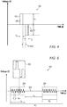
- Fig. 5 is a schematic illustration of a bipolar IRE pulse 100, in accordance with an embodiment of the invention.
- a curve 102 depicts the voltage V of bipolar IRE pulse 100 as a function of time t in an IRE ablation procedure.
- Bipolar IRE pulse 100 comprises a positive pulse 104 and a negative pulse 106, wherein the terms "positive” and “negative” refer to an arbitrarily chosen polarity of the two spines 30 between which the bipolar pulse is applied.
- the amplitude of positive pulse 104 is labeled as V+, and the temporal width of the pulse is labeled as t+.
- the amplitude of negative pulse 106 is labeled as V-, and the temporal width of the pulse is labeled as t-.
- the temporal spacing between positive pulse 104 and negative pulse 106 is labeled as t SPAcE .
- Typical values for the parameters of bipolar pulse 100 are given in Table 1, below.
- Fig. 5 is a schematic illustration of a burst 200 of bipolar pulses, in accordance with an embodiment of the invention.
- burst 200 comprises N T pulse trains 204, wherein each train comprises N P bipolar pulses 100.
- the length of pulse train 204 is labeled as t T .
- the period of bipolar pulses 100 within a pulse train 204 is labeled as t PP , and the interval between consecutive trains is labeled as ⁇ T , during which the signals are not applied.
- Typical values for the parameters of burst 200 are given in Table 1, below.
- Table 1 Typical values for the parameters of IRE signals Parameter Symbol Typical values Pulse amplitudes V+, V- 200-2000 V Pulse widths t+, t- 0.5-5 ⁇ s Spacing between positive and negative pulse t SPACE 0.1-5 ⁇ s Period of bipolar pulses in a pulse train t PP 1-20 ⁇ s Length of pulse train t T 5-100 ⁇ s Number of bipolar pulses in a pulse train N P 1-100 Spacing between consecutive pulse trains ⁇ T 0.3-1000 ms Number of pulse trains in a burst N T 1-100 Length of a burst 0-500 ms Energy per channel ⁇ 60 J Total time for IRE signal delivery ⁇ 10 s
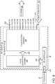
- Fig. 6 is a block diagram that schematically shows details of IRE module 34, in accordance with an embodiment of the invention.
- IRE module 34 comprises IRE generator 36 and IRE controller 38.
- IRE generator 36 comprises a pulse generation assembly 406 and a pulse routing assembly 408.
- Pulse generation assembly 406 is configured to receive control signals from IRE controller 38 (as described below) and to transmit sequences of bipolar pulses with an amplitude and duration responsive to the control signals.
- Pulse routing assembly 408 comprises a configurable network of switches, which are configured to receive control signals from IRE controller 38, to receive sequences of bipolar pulses from pulse generation assembly 405, and to select pairs of spines 30 responsively to the received control signals so as to the transmit the sequences of bipolar pulses through the selected pairs.
- IRE controller 38 communicates with processor 32 through bi-directional signals 410, wherein the processor communicates to the IRE controller commands reflecting setup parameters 66. IRE controller 38 further communicates to pulse generation assembly 406 digital command signals 418, derived from setup parameters 66, commanding IRE generator 36 to generate IRE pulses, such as those shown in Fig. 4 , above. These IRE pulses are sent to pulse routing assembly 408 as analog pulse signals 420, as directed by IRE controller 38.
- Pulse routing assembly 408 is coupled to spines 30 through output channels 422, as well as (optionally) to return patch 60 through a connection 424. For example, when pulse routing assembly 408 is coupled to six spines 30a-30f of basket assembly 31 ( Fig. 2 ), six of output channels 422 are coupled to the spines. Pulse routing assembly 408 is driven by IRE controller 38 to couple the IRE pulses into spines 30 as defined by setup parameters 66. Specifically, IRE controller 38 drives pulse routing assembly 408 to couple the IRE pulses to one or more selected pairs of spines 30. Routing assembly 408 may also electrically couple multiple spines 30 together to form a set that can serve as a "virtual electrode". Thus IRE controller 38 controls both the generation and the routing of the IRE pulses into spines 30.
- IRE generator 36 may alternatively comprise a different number of channels, for example 8, 16, or 20 channels, or any other suitable number of channels.
Landscapes
- Health & Medical Sciences (AREA)
- Life Sciences & Earth Sciences (AREA)
- Engineering & Computer Science (AREA)
- Surgery (AREA)
- Public Health (AREA)
- Animal Behavior & Ethology (AREA)
- Veterinary Medicine (AREA)
- General Health & Medical Sciences (AREA)
- Heart & Thoracic Surgery (AREA)
- Biomedical Technology (AREA)
- Otolaryngology (AREA)
- Medical Informatics (AREA)
- Molecular Biology (AREA)
- Nuclear Medicine, Radiotherapy & Molecular Imaging (AREA)
- Plasma & Fusion (AREA)
- Physics & Mathematics (AREA)
- Biophysics (AREA)
- Pulmonology (AREA)
- Anesthesiology (AREA)
- Hematology (AREA)
- Cardiology (AREA)
- Mechanical Engineering (AREA)
- Surgical Instruments (AREA)
Abstract
Description
- The present invention relates generally to medical equipment, and particularly to apparatus and methods for ablating tissue within the body.
- Irreversible electroporation (IRE) is a soft tissue ablation technique that applies short pulses of strong electrical fields to create permanent and hence lethal nanopores in the cell membrane, thus disrupting the cellular homeostasis (internal physical and chemical conditions). Cell death following IRE results from apoptosis (programmed cell death) and not necrosis (cell injury, which results in the destruction of a cell through the action of its own enzymes) as in other thermal and radiation-based ablation techniques. IRE is commonly used in tumor ablation in regions where precision and conservation of the extracellular matrix, blood flow and nerves are of importance.
- Embodiments of the present invention that are described hereinbelow provide improved systems and methods for ablation of tissue in the body.
- There is therefore provided, in accordance with an embodiment of the present invention, a medical apparatus, which includes a probe. The probe includes an insertion tube configured for insertion into a body cavity of a patient, a basket assembly connected distally to the insertion tube, and a plurality of resilient, conductive spines, which are configured to contact tissue within the body. The apparatus further includes an electrical signal generator configured to apply between one or more pairs of the spines bipolar pulses having an amplitude sufficient to cause irreversible electroporation (IRE) in the tissue contacted by the spines.
- In a disclosed embodiment, the spines have respective proximal and distal tips, wherein the proximal tips of the spines are joined mechanically at a proximal end of the basket assembly, and the distal tips of the spines are joined mechanically at a distal end of the basket assembly, and the spines bow radially outward when the basket assembly is deployed in the body cavity, thereby contacting the tissue in the body cavity.
- In a further disclosed embodiment, the basket assembly has a stable collapsed state, and the apparatus includes a puller attached to the distal end of the basket assembly and slidably disposed within the insertion tube, so that the spines bow radially outward in response to pulling the puller in a proximal direction through the insertion tube. Additionally or alternatively, the puller includes a reinforced polymer tube.
- In some embodiments, the insertion tube includes a flexible catheter configured for insertion into a chamber of a heart of the patient, and the spines are configured to contact and apply the electrical signals to myocardial tissue within the chamber.
- In additional embodiments, the spines include drawn metal ribbons, which may be fabricated from a nickel-titanium alloy. Additionally or alternatively, the spines include flexible printed circuit boards bonded to structural members.
- In disclosed embodiments, the bipolar pulses applied by the electrical signal generator include a sequence of bipolar pulses having an amplitude of at least 200 V, and a duration of each of the bipolar pulses is less than 20 µs. Additionally or alternatively, the sequence of the bipolar pulses includes pairs of pulses, wherein each pair includes a positive pulse and a negative pulse.
- In some embodiments, the electrical signal generator is configured to apply the bipolar pulses between first and second sets of the spines, wherein at least one of the sets includes two or more of the spines.
- In further embodiments, the apparatus includes a controller configured to transmit control signals to the electrical signal generator, wherein the electrical signal generator includes a pulse generation assembly, configured to receive the control signals from the controller and to transmit sequences of bipolar pulses with an amplitude and duration responsive to the control signals. The electrical signal generator further includes a pulse routing assembly, which includes a configurable network of switches, which are configured to receive the control signals from the controller, to receive the sequences of bipolar pulses from the pulse generation assembly, and to select sets of the spines responsively to the received control signals, each set including one or more of the spines, so as to the transmit the sequences of bipolar pulses through the selected sets.
- There is additionally provided, in accordance with an embodiment of the present invention, a method for medical treatment, the method including inserting a basket assembly including a plurality of resilient, conductive spines into a body cavity of a patient so that the spines contact tissue within the body cavity, and applying between two or more sets of the spines bipolar pulses having an amplitude sufficient to cause irreversible electroporation (IRE) in the tissue contacted by the spines, each set including one or more of the spines.
- The present invention will be more fully understood from the following detailed description of the embodiments thereof, taken together with the drawings in which:
-
-
Fig. 1 is a schematic pictorial illustration of a system used in an IRE ablation procedure, in accordance with embodiments of the invention; -
Fig. 2a is a schematic side view of a basket assembly, in accordance with an embodiment of the invention; -
Figs. 2b and 2c are schematic sectional views of spines in a basket assembly, in accordance with two embodiments of the invention; -
Figs. 3a and 3b are schematic side views of a basket assembly in its collapsed and expanded states, respectively, in accordance with an alternative embodiment of the invention; -
Fig. 4 is a schematic illustration of a bipolar IRE pulse, in accordance with an embodiment of the invention; -
Fig. 5 is a schematic illustration of a burst of bipolar pulses, in accordance with an embodiment of the invention; and -
Fig. 6 is a block diagram that schematically illustrates an IRE module, in accordance with an embodiment of the invention. - IRE is a predominantly non-thermal process, which causes an increase of the tissue temperature by, at most, a few degrees for a few seconds. It thus differs from RF (radio frequency) ablation, which raises the tissue temperature by between 20 and 70°C and destroys cells through heating. IRE utilizes bipolar pulses, i.e., combinations of positive and negative pulses, in order to avoid muscle contraction from a DC voltage. The pulses are applied, for example, between two bipolar electrodes of a catheter. Typically the electrodes are relatively small, for achieving a localized IRE in the tissue. However, the use of small electrodes reduces the size of the electroporated area.
- The embodiments of the present invention that are described herein address the problem of increasing the area of electroporation by providing a basket-type catheter with conductive spines, which contact tissue in a body cavity, such as myocardial tissue in the heart. Each spine acts as an electrode, and an electrical signal generator applies bipolar pulses between one or more pairs of the spines with an amplitude sufficient to cause IRE in the tissue contacted by the spines. The pairs of spines through which the pulses are applied are selected according to the region to be electroporated. Using complete spines as electrodes in this manner allows relatively large areas to be electroporated simultaneously.
- Additionally or alternatively, a set of multiple spines may be electrically connected together to create a larger "virtual electrode". IRE signals may be applied between one or more pairs of these "virtual electrodes" or sets.
- Catheters having an expandable basket assembly in accordance with embodiments of the invention are typically inserted into the heart through a narrow sheath, with the basket assembly in a collapsed state. For deployment in the body cavity, the basket assembly emerges out of the sheath and expands into its operational state. In some embodiments, the spines are made of a resilient material, which is fabricated so as to curve outward into the form of the basket when released from the sheath. The catheter may include a pusher tube within the insertion tube of the catheter. This pusher tube can be pushed distally at the conclusion of the ablation procedure in order to straighten the spines and thus collapse the basket assembly so that it may be pulled back into the sheath, thus facilitating the removal of the catheter from the subject.
- In other embodiments, the spines are fabricated so that the basket assembly is stable in a collapsed state rather than in an expanded state. A puller passing through the insertion tube is connected to the distal end of the basket assembly. After the basket assembly emerges from the sheath within a body cavity, pulling on the puller expands the assembly from its stable collapsed state to an expanded state and thus enables its deployment. By releasing the puller, the basket assembly reverts back to its collapsed state, and enables it to be pulled back into the insertion tube for the extraction of the catheter from the subject. This configuration is advantageous in that the puller is typically thinner and more flexible than a pusher tube, thus enabling the catheter to be made thinner and more flexible. The puller may comprise, for example, either a simple wire or alternatively a more complex assembly, such as a polymer tube with braiding or embedded wires to minimize its elongation.
-
Fig. 1 is a schematic pictorial illustration of asystem 20 used in an IRE ablation procedure, in accordance with embodiments of the invention. (In the following description, the IRE ablation procedure will also be referred to as "IRE ablation" or "IRE procedure.") In the pictured embodiment, aphysician 22 is performing an IRE ablation procedure in aheart 23 of subject 24 usingsystem 20.Physician 22 is performing the procedure using anablation catheter 26 comprising aninsertion tube 28 with alongitudinal axis 27, wherein adistal end 29 of the insertion tube is connected to abasket assembly 31 comprising multiple conductive spines 30 (shown in more detail inFigs. 2a, 2b and 2c ). -
IRE system 20 comprises aprocessor 32 and anIRE module 34.IRE module 34 comprises anIRE generator 36 and anIRE controller 38, wherein the IRE generator comprises a dedicated pulse generator, as described further hereinbelow.IRE generator 36 generates, under the control ofIRE controller 38, IRE signals, which comprise trains of bipolar electrical pulses. The pulses are directed to selectedspines 30, which serve as electrodes for performing an IRE procedure.Processor 32 handles the input and output interfaces betweenIRE system 20 andphysician 22, as well as the communication toIRE controller 38. The bipolar electrical pulses andIRE module 34 are further described below with reference toFigs.4 and 5 . -
Processor 32 andIRE controller 38 each typically comprises a programmable processor, which is programmed in software and/or firmware to carry out the functions that are described herein. Alternatively or additionally, each of them may comprise hard-wired and/or programmable hardware logic circuits, which carry out at least some of these functions.IRE generator 36 comprises analog and digital components and assemblies, for generating the IRE signals that are directed to spines 30. Althoughprocessor 32,IRE generator 36, andIRE controller 38 are shown in the figures, for the sake of simplicity, as separate, monolithic functional blocks, in practice some of these functions may be combined in a single processing and control unit. -
Processor 32 andIRE module 34 typically reside within aconsole 40.Console 40 comprisesinput devices 42, such as a keyboard and a mouse. Adisplay screen 44 is located in proximity to (or integral to)console 40.Display screen 44 may optionally comprise a touch screen, thus providing another input device. -
IRE system 20 may additionally comprise one or both of the following modules (typically residing within console 40), connected to suitable interfaces and devices in system 20: - An electrocardiogram (ECG)
module 46 is coupled through acable 48 toECG electrodes 50, which are attached to subject 24.ECG module 46 is configured to measure the electrical activity ofheart 23. - A
tracking module 52 is coupled to one or moreelectromagnetic position sensors 54 in the distal end ofinsertion tube 28, and possibly withinbasket assembly 31, as well. In the presence of an external magnetic field generated by one or more magnetic-field generators 56,electromagnetic position sensors 54 output signals that vary with the positions of the sensors. Based on these signals, trackingmodule 52 tracks the positions ofspines 30 inheart 23. - The
above modules -
Catheter 26 is coupled to console 40 via anelectrical interface 58, such as a port or socket. IRE signals are thus carried fromIRE generator 36 viainterface 58 and wiring insideinsertion tube 28 tospines 30 inbasket assembly 31. Similarly, signals for tracking the position and orientation ofdistal end 28 may be received by trackingmodule 52 viainterface 58. - An
external electrode 60, or "return patch," may be additionally coupled externally between subject 24, typically on the skin of the subject's torso, andIRE module 34.External electrode 60 may be used for coupling IRE signals between one ofspines 30 and the external electrode, thus achieving electroporation that is localized deeper intissue 62. -
Processor 32 receives from physician 22 (or from another user), prior to and/or during the IRE procedure,setup parameters 66 for the procedure. Using one or moresuitable input devices 42,physician 22 setssetup parameters 66, selecting one or more pairs ofspines 30 to serve as electrodes for activation (for receiving the IRE signals) and the order in which the electrodes are activated, as well as defining the characteristics (timing and amplitude) of the IRE signals. Additionally,processor 32 may displaysetup parameters 66 ondisplay screen 26. As used herein the pairs of spines are not limited to adjacent spines but in all possible configurations that allow for delivery of biphasic energy between (a) two singular spines acting as two separate electrodes or (b) between two groups of multiple spines. For case (a) one example of two singular spines acting as an electrode "pair" in (a) isspine 30a inFig. 2 adjacent withspine 30b to define a "pair of electrodes" when biphasic voltage is delivered to thesespines spine 30a can be paired with anon-neighobring spine 30c as "another pair";spine 30a withnon-neighboring spine 30d as yet another "pair";spine 30a withdistant spine 30f as a further "pair";spine 30b withdistant spine 30d as yet a "pair". In a further variation,spines spines spines spines Fig. 2 can be utilized to define two electrode pairs:spines spines 30c+30d (one electrode) and another group ofspines 30e+30f (as another electrode) to define the second electrode pair inFig. 2 (i.e., 30a+30b as the first pair of electrodes; 30c and 30d + 30e and 30f as the second pair of electrodes). - In some embodiments,
processor 32 displays ondisplay 44, based on signals received from trackingmodule 60, arelevant image 68 of the subject's anatomy, such as a map of a chamber ofheart 23, which is annotated, for example, to show the current position and orientation ofbasket assembly 31. Alternatively or additionally, based on signals received fromECG module 46,processor 32 may display ondisplay screen 44 the electrical activity ofheart 23. - To begin the procedure,
physician 22inserts catheter 26 into subject 24, for example through the subject's vascular system, and then navigatesinsertion tube 28, using acontrol handle 70, to an appropriate site within, or external to,heart 23. At the insertion and navigation stage,basket assembly 31 is in a collapsed form, generally inside a sheath (not shown), in order to provide for an easy insertion into subject 24. - Once
insertion tube 28 is positioned in the required area withinheart 23,basket assembly 31 is advanced from the sheath, assuming an expanded form. A further detailed description ofbasket assembly 31 is given inFig. 2 , below. As shown schematically in aninset 71,physician 22 now bringsbasket assembly 31 into contact withtissue 62 ofheart 23, such as myocardial or epicardial tissue. Next,IRE generator 36, under the control ofIRE controller 38, generates IRE signals comprising trains of pulses (shown in detail inFig. 5 ). The IRE signals are carried throughcatheter 26, over different respective electrical conductors (not shown), to pairs ofspines 30, such thatcurrents 72 generated by the IRE signals flow between the spines in each pair (bipolar ablation), and perform the desired irreversible electroporation oftissue 62 over the extended area between the spines. -
Fig. 2a is a schematic side view ofbasket assembly 31, in accordance with an embodiment of the invention.Basket assembly 31 comprisesspines 30, which are inFig. 2 labelled individually as 30a, 30b, 30c, 30d, 30e, and 30f.Spines 30a-30f comprise long segments of a resilient material, which is conductive or has a conductive coating or a conductive member attached to it. For example,spines 30a-30f may comprise a nickel-titanium alloy, known as nitinol. -
Proximal tips 74 ofspines 30a-30f are joined mechanically atproximal end 76 ofbasket assembly 31, anddistal tips 78 of the spines are joined mechanically at adistal end 80 of the basket assembly. (Proximal anddistal tips spines 30a-30f, however, are insulated electrically from one another so that the spines can serve as separate electrodes.)Spines 30a-30f are fabricated so thatbasket assembly 31 has an expanded state as its stable state. Thus,spines 30a-30f bow radially outward when the basket assembly is deployed in a body cavity, thereby contactingtissue 62 in the body cavity.Spines 30a-30f are electrically coupled via conductors withincatheter 26 to IRE generator 36 (Fig. 1 ) for receiving IRE ablation signals. - The IRE signals received from
IRE generator 36 are coupled, for example, betweenspines Fig. 1 ) flow betweenspines tissue 62. For example, applyingbasket assembly 31 to pulmonary vein ablation will cause electroporation over a 6-12 mm wide ring around the pulmonary vein. - The IRE signals may be coupled between any pair of
spines 30a-30f, although typically the signals will be applied between pairs of adjacent spines. Additionally or alternatively, the signals may be applied simultaneously or in alternation between several pairs of spines. Althoughbasket assembly 31 is depicted inFig. 2 to comprise six spines, other numbers of spines, both smaller and larger than six, may be used. Additionally or alternatively, a set ofmultiple spines 30 may be electrically connected together to form a larger "virtual electrode" comprising multiple spines. IRE signals may be applied between one or more pairs of these "virtual electrodes" or sets. -
Figs. 2b and 2c are schematic sectional views ofspines 30, in accordance with two embodiments of the invention. -
Fig. 2b is a schematic sectional view ofspine 30, wherein the spine comprises a drawnnitinol ribbon 33.Nitinol ribbon 33 serves both as a structural member ofspine 30 and as an electrical conductor for currents 72 (Fig. 1 ). Formingnitinol ribbon 33 by the process of drawing is advantageous in that resulting edges 35 of the ribbon are rounded (as opposed to sharp edges formed in a ribbon cut from a sheet of nitinol), thus avoiding damage totissue 62 touched byspines 30. -
Fig. 2c is a schematic sectional view ofspine 30 in an alternative embodiment, whereinspine 30 comprises a composite of astructural member 37 and aconductive member 39.Structural member 37 comprises, for example, as inFig. 2b , a drawn nitinol ribbon.Conductive member 39 comprises a conductive film, such as gold, which is disposed on a flexible printed circuit board (PCB) 41, which in turn is bonded tostructural member 37 with suitable bonding and insulatingmaterials 43, such as a biocompatible epoxy or other adhesive. Thus,structural member 37 is insulated fromtissue 62, andcurrents 72 are conducted to the tissue byconductive member 39, which is exposed to the tissue. - Alternatively,
spine 30 may comprise a conductive or non-conductive structural member with a conductive coating (not shown). -
Figs. 3a and 3b are schematic side views of abasket assembly 90 in its collapsed and expanded states, respectively, in accordance with an alternative embodiment of the invention. The same numerical labels as inFigs. 1 and2 are used for similar items inFigs. 3a and 3b . As inFigs. 2a ,3a, and 3b ,spines 30 comprise long segments of a resilient material, which is conductive, or has a conductive coating or a conductive member attached to it. -
Fig. 3a showsbasket assembly 90 in its collapsed state, in which spines 30 are straight and aligned parallel tolongitudinal axis 27. This is the stable state of basket assembly 90: When it is pushed out of the sheath,assembly 90 remains in the collapsed state, unless forced into an expanded state.Ablation catheter 26 contains apuller 92, which extends through and is able to move longitudinally withininsertion tube 28.Puller 92 has adistal end 94 attached todistal end 80 ofbasket assembly 90, and a proximal end (not shown) attached to controlhandle 70. Since proximal ends 74 ofspines 30 are secured toinsertion tube 28, pullingpuller 92 from its proximal end shortens the distance between the respective distal and proximal ends 78 and 74 ofspines 30, and thereby causes the spines to bow outward for deployment, as shown inFig. 3b . Releasingpuller 92 allowsbasket assembly 90 to collapse back to its stable state (Fig. 3a ), due to the resilience ofspines 30, for extractingcatheter 26 from subject 24. -
Puller 92 may comprise any suitable elongated component having sufficient tensile strength and bending flexibility. For example,puller 92 may comprise a simple wire. Alternatively,puller 92 may comprise a more complex structure, such as a polymer tube with reinforcement in the form of braiding or embedded wires to minimize its elongation. -
Fig. 5 is a schematic illustration of abipolar IRE pulse 100, in accordance with an embodiment of the invention. - A
curve 102 depicts the voltage V ofbipolar IRE pulse 100 as a function of time t in an IRE ablation procedure.Bipolar IRE pulse 100 comprises apositive pulse 104 and anegative pulse 106, wherein the terms "positive" and "negative" refer to an arbitrarily chosen polarity of the twospines 30 between which the bipolar pulse is applied. The amplitude ofpositive pulse 104 is labeled as V+, and the temporal width of the pulse is labeled as t+. Similarly, the amplitude ofnegative pulse 106 is labeled as V-, and the temporal width of the pulse is labeled as t-. The temporal spacing betweenpositive pulse 104 andnegative pulse 106 is labeled as tSPAcE. Typical values for the parameters ofbipolar pulse 100 are given in Table 1, below. -
Fig. 5 is a schematic illustration of aburst 200 of bipolar pulses, in accordance with an embodiment of the invention. - In an IRE procedure, the IRE signals are delivered to
spines 30 as one ormore bursts 200, depicted by acurve 202.Burst 200 comprises NT pulse trains 204, wherein each train comprises NPbipolar pulses 100. The length ofpulse train 204 is labeled as tT. The period ofbipolar pulses 100 within apulse train 204 is labeled as tPP, and the interval between consecutive trains is labeled as ΔT, during which the signals are not applied. Typical values for the parameters ofburst 200 are given in Table 1, below.Table 1: Typical values for the parameters of IRE signals Parameter Symbol Typical values Pulse amplitudes V+, V- 200-2000 V Pulse widths t+, t- 0.5-5 µs Spacing between positive and negative pulse tSPACE 0.1-5 µs Period of bipolar pulses in a pulse train tPP 1-20 µs Length of pulse train tT 5-100 µs Number of bipolar pulses in a pulse train NP 1-100 Spacing between consecutive pulse trains ΔT 0.3-1000 ms Number of pulse trains in a burst NT 1-100 Length of a burst 0-500 ms Energy per channel ≤60 J Total time for IRE signal delivery ≤10 s -
Fig. 6 is a block diagram that schematically shows details ofIRE module 34, in accordance with an embodiment of the invention. As explained above in regard toFig. 1 ,IRE module 34 comprisesIRE generator 36 andIRE controller 38.IRE generator 36 comprises apulse generation assembly 406 and apulse routing assembly 408.Pulse generation assembly 406 is configured to receive control signals from IRE controller 38 (as described below) and to transmit sequences of bipolar pulses with an amplitude and duration responsive to the control signals.Pulse routing assembly 408 comprises a configurable network of switches, which are configured to receive control signals fromIRE controller 38, to receive sequences of bipolar pulses from pulse generation assembly 405, and to select pairs ofspines 30 responsively to the received control signals so as to the transmit the sequences of bipolar pulses through the selected pairs. -
IRE controller 38 communicates withprocessor 32 throughbi-directional signals 410, wherein the processor communicates to the IRE controller commands reflectingsetup parameters 66.IRE controller 38 further communicates topulse generation assembly 406 digital command signals 418, derived fromsetup parameters 66, commandingIRE generator 36 to generate IRE pulses, such as those shown inFig. 4 , above. These IRE pulses are sent topulse routing assembly 408 as analog pulse signals 420, as directed byIRE controller 38. -
Pulse routing assembly 408 is coupled tospines 30 throughoutput channels 422, as well as (optionally) to returnpatch 60 through aconnection 424. For example, whenpulse routing assembly 408 is coupled to sixspines 30a-30f of basket assembly 31 (Fig. 2 ), six ofoutput channels 422 are coupled to the spines.Pulse routing assembly 408 is driven byIRE controller 38 to couple the IRE pulses intospines 30 as defined bysetup parameters 66. Specifically,IRE controller 38 drives pulse routingassembly 408 to couple the IRE pulses to one or more selected pairs ofspines 30.Routing assembly 408 may also electrically couplemultiple spines 30 together to form a set that can serve as a "virtual electrode". ThusIRE controller 38 controls both the generation and the routing of the IRE pulses intospines 30. - Although
Fig. 6 shows tenchannels 422,IRE generator 36 may alternatively comprise a different number of channels, for example 8, 16, or 20 channels, or any other suitable number of channels. - It will be appreciated that the embodiments described above are cited by way of example, and that the present invention is not limited to what has been particularly shown and described hereinabove. Rather, the scope of the present invention includes both combinations and subcombinations of the various features described hereinabove, as well as variations and modifications thereof which would occur to persons skilled in the art upon reading the foregoing description and which are not disclosed in the prior art.
-
- 1. A method for medical treatment, comprising:
- inserting a basket assembly comprising a plurality of conductive spines into a body cavity of a patient so that the spines contact tissue within the body cavity; and
- applying between two or more sets of the spines bipolar pulses having an amplitude sufficient to cause irreversible electroporation (IRE) in the tissue contacted by the spines, each set comprising one or more of the spines.
- 2. The method according to aspect 1, wherein at least one of the sets of the spines comprises multiple spines.
- 3. The method according to aspect 1, wherein the spines have respective proximal and distal tips, wherein the proximal tips of the spines are joined mechanically at a proximal end of the basket assembly, and the distal tips of the spines are joined mechanically at a distal end of the basket assembly, and the spines bow radially outward when the basket assembly is deployed in the body cavity, thereby contacting the tissue in the body cavity.
- 4. The method according to aspect 3, wherein the basket assembly has a stable collapsed state, and wherein inserting the basket assembly comprises pulling a puller attached to the distal end of the basket assembly in a proximal direction, so that the spines bow radially outward.
- 5. The method according to aspect 1, wherein inserting the basket assembly comprises inserting a catheter, with the basket assembly connected to a distal end of the catheter into a chamber of a heart of the patient, whereby the spines contact and apply the electrical signals to myocardial tissue within the chamber.
- 6. The method according to aspect 1, wherein the spines comprise a nickel-titanium alloy.
- 7. The method according to aspect 1, wherein applying the bipolar pulses comprises applying a sequence of bipolar pulses having an amplitude of at least 200 V, wherein a duration of each of the bipolar pulses is less than 20 µs.
- 8. The method according to aspect 7, wherein applying the sequence of bipolar pulses comprises applying pairs of pulses, wherein each pair comprises a positive pulse and a negative pulse.
- 9. The method according to aspect 1, wherein applying the bipolar pulses comprises:
- generating sequences of bipolar pulses with a specified amplitude and duration;
- selecting the sets of the spines; and
- transmitting the sequences of bipolar pulses through the selected sets.
Claims (12)
- A medical apparatus, comprising:a probe, comprising:an insertion tube configured for insertion into a body cavity of a patient; anda basket assembly connected distally to the insertion tube and comprising a plurality of conductive spines, which are configured to contact tissue within the body; andan electrical signal generator configured to apply between one or more pairs of the spines bipolar pulses having an amplitude sufficient to cause irreversible electroporation (IRE) in the tissue contacted by the spines.
- The apparatus according to claim 1, wherein the spines have respective proximal and distal tips, wherein the proximal tips of the spines are joined mechanically at a proximal end of the basket assembly, and the distal tips of the spines are joined mechanically at a distal end of the basket assembly, and the spines bow radially outward when the basket assembly is deployed in the body cavity, thereby contacting the tissue in the body cavity.
- The apparatus according to claim 2, wherein the basket assembly has a stable collapsed state, and wherein the apparatus comprises a puller attached to the distal end of the basket assembly and slidably disposed within the insertion tube, so that the spines bow radially outward in response to pulling the puller in a proximal direction through the insertion tube.
- The apparatus according to claim 3, wherein the puller comprises a reinforced polymer tube.
- The apparatus according to claim 1, wherein the insertion tube comprises a catheter configured for insertion into a chamber of a heart of the patient, and the spines are configured to contact and apply the electrical signals to myocardial tissue within the chamber.
- The apparatus according to claim 1, wherein the spines comprise drawn metal ribbons.
- The apparatus according to claim 6, wherein the metal ribbons comprise a nickel-titanium alloy.
- The apparatus according to claim 1, wherein the spines comprise flexible printed circuit boards bonded to structural members.
- The apparatus according to claim 1, wherein the bipolar pulses applied by the electrical signal generator comprise a sequence of bipolar pulses having an amplitude of at least 200 V, and a duration of each of the bipolar pulses is less than 20 µs.
- The apparatus according to claim 9, wherein the sequence of the bipolar pulses comprises pairs of pulses, wherein each pair comprises a positive pulse and a negative pulse.
- The apparatus according to claim 1, wherein the electrical signal generator is configured to apply the bipolar pulses between first and second sets of the spines, wherein at least one of the sets comprises two or more of the spines.
- The apparatus according to claim 1, and comprising a controller configured to transmit control signals to the electrical signal generator, wherein the electrical signal generator comprises:a pulse generation assembly, configured to receive the control signals from the controller and to transmit sequences of bipolar pulses with an amplitude and duration responsive to the control signals; anda pulse routing assembly, comprising a configurable network of switches, which are configured to receive the control signals from the controller, to receive the sequences of bipolar pulses from the pulse generation assembly, and to select sets of the spines responsively to the received control signals, each set comprising one or more of the spines, so as to the transmit the sequences of bipolar pulses through the selected sets.
Applications Claiming Priority (1)
| Application Number | Priority Date | Filing Date | Title |
|---|---|---|---|
| US16/842,648 US20210307815A1 (en) | 2020-04-07 | 2020-04-07 | Basket Catheter with Solid Conducting Spines as Electrodes for IRE |
Publications (2)
| Publication Number | Publication Date |
|---|---|
| EP3892220A1 true EP3892220A1 (en) | 2021-10-13 |
| EP3892220B1 EP3892220B1 (en) | 2025-07-23 |
Family
ID=75426344
Family Applications (1)
| Application Number | Title | Priority Date | Filing Date |
|---|---|---|---|
| EP21166943.7A Active EP3892220B1 (en) | 2020-04-07 | 2021-04-06 | Basket catheter with solid conducting spines as electrodes for ire |
Country Status (5)
| Country | Link |
|---|---|
| US (1) | US20210307815A1 (en) |
| EP (1) | EP3892220B1 (en) |
| JP (1) | JP7657643B2 (en) |
| CN (1) | CN113491572A (en) |
| IL (1) | IL282052A (en) |
Cited By (5)
| Publication number | Priority date | Publication date | Assignee | Title |
|---|---|---|---|---|
| EP4197467A1 (en) * | 2021-12-17 | 2023-06-21 | Biosense Webster (Israel) Ltd | High-frequency tissue ablation using coated electrodes |
| US12076071B2 (en) | 2020-08-14 | 2024-09-03 | Kardium Inc. | Systems and methods for treating tissue with pulsed field ablation |
| WO2025042913A1 (en) * | 2023-08-24 | 2025-02-27 | Boston Scientific Scimed, Inc. | Wide-area focal ablation catheter having insulated portions |
| WO2025042905A1 (en) * | 2023-08-24 | 2025-02-27 | Boston Scientific Scimed, Inc. | Spline-based ablation catheter having retainer feature |
| WO2026050275A1 (en) * | 2024-08-29 | 2026-03-05 | Boston Scientific Scimed, Inc. | Pfa catheter electrode connections |
Families Citing this family (41)
| Publication number | Priority date | Publication date | Assignee | Title |
|---|---|---|---|---|
| US10905329B2 (en) | 2016-06-09 | 2021-02-02 | Biosense Webster (Israel) Ltd. | Multi-function conducting elements for a catheter |
| US12029545B2 (en) | 2017-05-30 | 2024-07-09 | Biosense Webster (Israel) Ltd. | Catheter splines as location sensors |
| US20190314083A1 (en) | 2018-04-11 | 2019-10-17 | Biosense Webster (Israel) Ltd. | Flexible Multi-Arm Catheter with Diametrically Opposed Sensing Electrodes |
| US11045628B2 (en) | 2018-12-11 | 2021-06-29 | Biosense Webster (Israel) Ltd. | Balloon catheter with high articulation |
| US11207016B2 (en) | 2018-12-28 | 2021-12-28 | Biosense Webster (Israel) Ltd. | Mapping ECG signals using a multipole electrode assembly |
| US11850051B2 (en) | 2019-04-30 | 2023-12-26 | Biosense Webster (Israel) Ltd. | Mapping grid with high density electrode array |
| US11712172B2 (en) | 2019-07-18 | 2023-08-01 | Biosense Webster (Israel) Ltd. | Visual guidance for positioning a distal end of a medical probe |
| US11759150B2 (en) | 2019-08-27 | 2023-09-19 | Biosense Webster (Israel) Ltd. | Accurate basket catheter tracking |
| US11950930B2 (en) | 2019-12-12 | 2024-04-09 | Biosense Webster (Israel) Ltd. | Multi-dimensional acquisition of bipolar signals from a catheter |
| US11517218B2 (en) | 2019-12-20 | 2022-12-06 | Biosense Webster (Israel) Ltd. | Selective graphical presentation of electrophysiological parameters |
| US12232874B2 (en) | 2020-05-29 | 2025-02-25 | Biosense Webster (Israel) Ltd. | Electrode apparatus for diagnosis of arrhythmias |
| US11987017B2 (en) | 2020-06-08 | 2024-05-21 | Biosense Webster (Israel) Ltd. | Features to assist in assembly and testing of devices |
| US12048479B2 (en) | 2020-09-10 | 2024-07-30 | Biosense Webster (Israel) Ltd. | Surface mounted electrode catheter |
| US11950840B2 (en) | 2020-09-22 | 2024-04-09 | Biosense Webster (Israel) Ltd. | Basket catheter having insulated ablation electrodes |
| US11950841B2 (en) | 2020-09-22 | 2024-04-09 | Biosense Webster (Israel) Ltd. | Basket catheter having insulated ablation electrodes and diagnostic electrodes |
| US12082875B2 (en) | 2020-09-24 | 2024-09-10 | Biosense Webster (Israel) Ltd | Balloon catheter having a coil for sensing tissue temperature and position of the balloon |
| US11974803B2 (en) | 2020-10-12 | 2024-05-07 | Biosense Webster (Israel) Ltd. | Basket catheter with balloon |
| US12201786B2 (en) | 2020-12-17 | 2025-01-21 | Biosense Webster (Israel) Ltd. | Measurement of distal end dimension of catheters using magnetic fields |
| US11918383B2 (en) | 2020-12-21 | 2024-03-05 | Biosense Webster (Israel) Ltd. | Visualizing performance of catheter electrodes |
| DE112021007139T5 (en) * | 2021-02-22 | 2023-11-30 | Japan Lifeline Co., Ltd. | Power supply device and ablation system |
| US12064170B2 (en) | 2021-05-13 | 2024-08-20 | Biosense Webster (Israel) Ltd. | Distal assembly for catheter with lumens running along spines |
| US12364426B2 (en) | 2021-08-12 | 2025-07-22 | Biosense Webster (Israel) Ltd. | Electro-anatomical mapping and annotation presented in electrophysiological procedures |
| US12004804B2 (en) | 2021-09-09 | 2024-06-11 | Biosense Webster (Israel) Ltd. | Basket catheter with mushroom shape distal tip |
| US12478424B2 (en) | 2021-09-10 | 2025-11-25 | Biosense Webster (Israel) Ltd. | Staggered pairs of biased ablation electrodes on basket catheter |
| US12011280B2 (en) | 2021-10-04 | 2024-06-18 | Biosense Webster (Israel) Ltd. | Electrophysiological mapping in the presence of injury current |
| US12533489B2 (en) | 2021-10-08 | 2026-01-27 | Biosense Webster (Israel) Ltd. | Measuring tissue proximity for multi-electrode catheter |
| US20230181242A1 (en) | 2021-12-10 | 2023-06-15 | Biosense Webster (Israel) Ltd. | Basket Catheter with Electrically-Connected Spines Forming a Distributed Electrode |
| US12551271B2 (en) | 2021-12-17 | 2026-02-17 | Biosense Webster (Israel) Ltd. | Basket catheter with cushioning porous sheath cover |
| US12419683B2 (en) | 2021-12-22 | 2025-09-23 | Biosense Webster (Israel) Ltd. | Irreversible electroporation with shorted electrodes |
| US12440263B2 (en) | 2022-01-20 | 2025-10-14 | Biosense Webster (Israel) Ltd. | Systems and methods for tripodic spines forming a spherical basket for improved tissue contact and current delivery |
| US12484961B2 (en) | 2022-01-20 | 2025-12-02 | Biosense Webster (Israel) Ltd. | Mechanical retainer systems for electrodes of a basket catheter, and methods of the same |
| US12446946B2 (en) | 2022-01-20 | 2025-10-21 | Biosense Webster (Israel) Ltd. | Systems and methods for a single spiral electrode assembly forming a spherical basket for improved tissue contact and current delivery |
| US12616517B2 (en) | 2022-03-25 | 2026-05-05 | Biosense Webster (Israel) Ltd. | Expandable basket assemblies with linear spine patterns for improved tissue contact and methods for making thereof |
| US20230346464A1 (en) * | 2022-04-28 | 2023-11-02 | Biosense Webster (Israel) Ltd. | Basket catheter with cloverleaf structure to prevent buckling and retention feature for electrodes |
| US12616518B2 (en) | 2022-04-28 | 2026-05-05 | Biosense Webster (Israel) Ltd. | Barrel electrodes for a basket catheter, and methods of the same |
| US12471989B2 (en) | 2022-04-28 | 2025-11-18 | Biosense Webster (Israel) Ltd. | Strengthened expandable baskets for medical probes and medical probes containing strengthen expandable baskets |
| EP4356857A1 (en) | 2022-10-19 | 2024-04-24 | Biosense Webster (Israel) Ltd. | Basket catheter with porous sheath |
| US12616519B2 (en) * | 2022-12-15 | 2026-05-05 | Biosense Webster (Israel) Ltd. | Basket assembly with atraumatic tip electrode and methods of making thereof |
| US12533185B2 (en) | 2022-12-28 | 2026-01-27 | Biosense Webster (Israel) Ltd. | Basket end effector with distal position sensor |
| US12521035B2 (en) | 2022-12-29 | 2026-01-13 | Biosense Webster (Israel) Ltd. | Cylindrical cage systems and methods for distributed tissue contact for mapping and ablation |
| US20240407850A1 (en) | 2023-06-09 | 2024-12-12 | Biosense Webster (Israel) Ltd. | Basket catheter with deformation sensor relying on eddy current |
Citations (4)
| Publication number | Priority date | Publication date | Assignee | Title |
|---|---|---|---|---|
| WO2014124231A1 (en) * | 2013-02-08 | 2014-08-14 | Acutus Medical, Inc. | Expandable catheter assembly with flexible printed circuit board |
| WO2014195933A1 (en) * | 2013-06-05 | 2014-12-11 | Tel Hashomer Medical Research Infrastructure And Services Ltd. | Myocardial ablation by irreversible electroporation |
| WO2015171921A2 (en) * | 2014-05-07 | 2015-11-12 | Mickelson Steven R | Methods and apparatus for selective tissue ablation |
| EP3178429A1 (en) * | 2015-12-07 | 2017-06-14 | Biosense Webster (Israel) Ltd. | Basket catheter with an improved seal |
Family Cites Families (9)
| Publication number | Priority date | Publication date | Assignee | Title |
|---|---|---|---|---|
| US5415166A (en) * | 1991-02-15 | 1995-05-16 | Cardiac Pathways Corporation | Endocardial mapping apparatus and cylindrical semiconductor device mounting structure for use therewith and method |
| US7198635B2 (en) * | 2000-10-17 | 2007-04-03 | Asthmatx, Inc. | Modification of airways by application of energy |
| US7653438B2 (en) * | 2002-04-08 | 2010-01-26 | Ardian, Inc. | Methods and apparatus for renal neuromodulation |
| WO2009121009A2 (en) * | 2008-03-27 | 2009-10-01 | The Regents Of The University Of California | Irreversible electroporation device for use in attenuating neointimal |
| US11364072B2 (en) | 2017-01-27 | 2022-06-21 | Medtronic, Inc. | Catheter electrodes for energy management |
| US11647935B2 (en) * | 2017-07-24 | 2023-05-16 | St. Jude Medical, Cardiology Division, Inc. | Masked ring electrodes |
| US20190350649A1 (en) | 2018-05-21 | 2019-11-21 | St. Jude Medical, Cardiology Division, Inc. | Radio-frequency ablation and direct current electroporation catheters |
| US11523838B2 (en) * | 2019-06-12 | 2022-12-13 | Covidien Lp | Retrieval of material from corporeal lumens |
| JP7459252B2 (en) | 2019-12-03 | 2024-04-01 | セント・ジュード・メディカル,カーディオロジー・ディヴィジョン,インコーポレイテッド | Electroporation system and method |
-
2020
- 2020-04-07 US US16/842,648 patent/US20210307815A1/en active Pending
-
2021
- 2021-04-04 IL IL282052A patent/IL282052A/en unknown
- 2021-04-06 JP JP2021064609A patent/JP7657643B2/en active Active
- 2021-04-06 EP EP21166943.7A patent/EP3892220B1/en active Active
- 2021-04-07 CN CN202110371914.9A patent/CN113491572A/en active Pending
Patent Citations (4)
| Publication number | Priority date | Publication date | Assignee | Title |
|---|---|---|---|---|
| WO2014124231A1 (en) * | 2013-02-08 | 2014-08-14 | Acutus Medical, Inc. | Expandable catheter assembly with flexible printed circuit board |
| WO2014195933A1 (en) * | 2013-06-05 | 2014-12-11 | Tel Hashomer Medical Research Infrastructure And Services Ltd. | Myocardial ablation by irreversible electroporation |
| WO2015171921A2 (en) * | 2014-05-07 | 2015-11-12 | Mickelson Steven R | Methods and apparatus for selective tissue ablation |
| EP3178429A1 (en) * | 2015-12-07 | 2017-06-14 | Biosense Webster (Israel) Ltd. | Basket catheter with an improved seal |
Cited By (5)
| Publication number | Priority date | Publication date | Assignee | Title |
|---|---|---|---|---|
| US12076071B2 (en) | 2020-08-14 | 2024-09-03 | Kardium Inc. | Systems and methods for treating tissue with pulsed field ablation |
| EP4197467A1 (en) * | 2021-12-17 | 2023-06-21 | Biosense Webster (Israel) Ltd | High-frequency tissue ablation using coated electrodes |
| WO2025042913A1 (en) * | 2023-08-24 | 2025-02-27 | Boston Scientific Scimed, Inc. | Wide-area focal ablation catheter having insulated portions |
| WO2025042905A1 (en) * | 2023-08-24 | 2025-02-27 | Boston Scientific Scimed, Inc. | Spline-based ablation catheter having retainer feature |
| WO2026050275A1 (en) * | 2024-08-29 | 2026-03-05 | Boston Scientific Scimed, Inc. | Pfa catheter electrode connections |
Also Published As
| Publication number | Publication date |
|---|---|
| JP7657643B2 (en) | 2025-04-07 |
| CN113491572A (en) | 2021-10-12 |
| US20210307815A1 (en) | 2021-10-07 |
| IL282052A (en) | 2021-10-31 |
| JP2021164638A (en) | 2021-10-14 |
| EP3892220B1 (en) | 2025-07-23 |
Similar Documents
| Publication | Publication Date | Title |
|---|---|---|
| EP3892220B1 (en) | Basket catheter with solid conducting spines as electrodes for ire | |
| US20250064511A1 (en) | Methods and apparatus for multi-catheter tissue ablation | |
| US20220071694A1 (en) | IRE Ablation Systems and Protocols Using a Basket Catheter | |
| US12396790B2 (en) | Temperature controlled short duration ablation with multiple electrodes | |
| KR102868326B1 (en) | Pulsed field ablation device and method | |
| JP7658522B2 (en) | IRE temperature control | |
| US12290306B2 (en) | Using unipolar configuration for irreversible-electroporation (IRE) | |
| EP4069116A1 (en) | Pulse generator for irreversible electroporation | |
| CN113365566A (en) | Electroporation system and method | |
| EP4039210A1 (en) | Virtually-shorted electrodes for an ire pulse generator | |
| US20210161593A1 (en) | Pulse Generator for Irreversible Electroporation | |
| EP4079244A1 (en) | Ire ablation systems and protocols using a basket catheter | |
| CN114027967A (en) | Pulsed electric field balloon component and ablation catheter device using same | |
| WO2023205577A1 (en) | Systems for electroporation using arbitrary electrode addressing | |
| EP4091564A1 (en) | Improving efficiency of ire ablation procedure by applying stress signal to target tissue | |
| US12102374B2 (en) | Pulse generator for irreversible electroporation with switchable pulse application | |
| CN216495608U (en) | Pulsed electric field balloon component and ablation catheter device applying same | |
| CN114948183A (en) | Fast switching pulse generator | |
| US20220346857A1 (en) | Tissue ablation using high-frequency unipolar ire | |
| RU2776694C1 (en) | Virtually closed electrodes for an ire pulse generator | |
| CN117426863A (en) | Tissue ablation using high-frequency monopolar IRE |
Legal Events
| Date | Code | Title | Description |
|---|---|---|---|
| PUAI | Public reference made under article 153(3) epc to a published international application that has entered the european phase |
Free format text: ORIGINAL CODE: 0009012 |
|
| STAA | Information on the status of an ep patent application or granted ep patent |
Free format text: STATUS: THE APPLICATION HAS BEEN PUBLISHED |
|
| AK | Designated contracting states |
Kind code of ref document: A1 Designated state(s): AL AT BE BG CH CY CZ DE DK EE ES FI FR GB GR HR HU IE IS IT LI LT LU LV MC MK MT NL NO PL PT RO RS SE SI SK SM TR |
|
| STAA | Information on the status of an ep patent application or granted ep patent |
Free format text: STATUS: REQUEST FOR EXAMINATION WAS MADE |
|
| 17P | Request for examination filed |
Effective date: 20220412 |
|
| RBV | Designated contracting states (corrected) |
Designated state(s): AL AT BE BG CH CY CZ DE DK EE ES FI FR GB GR HR HU IE IS IT LI LT LU LV MC MK MT NL NO PL PT RO RS SE SI SK SM TR |
|
| RAP3 | Party data changed (applicant data changed or rights of an application transferred) |
Owner name: BIOSENSE WEBSTER (ISRAEL) LTD. |
|
| GRAP | Despatch of communication of intention to grant a patent |
Free format text: ORIGINAL CODE: EPIDOSNIGR1 |
|
| STAA | Information on the status of an ep patent application or granted ep patent |
Free format text: STATUS: GRANT OF PATENT IS INTENDED |
|
| RIC1 | Information provided on ipc code assigned before grant |
Ipc: A61B 18/12 20060101ALN20241205BHEP Ipc: A61B 18/00 20060101ALN20241205BHEP Ipc: A61B 18/14 20060101AFI20241205BHEP |
|
| INTG | Intention to grant announced |
Effective date: 20250102 |
|
| GRAS | Grant fee paid |
Free format text: ORIGINAL CODE: EPIDOSNIGR3 |
|
| GRAA | (expected) grant |
Free format text: ORIGINAL CODE: 0009210 |
|
| STAA | Information on the status of an ep patent application or granted ep patent |
Free format text: STATUS: THE PATENT HAS BEEN GRANTED |
|
| AK | Designated contracting states |
Kind code of ref document: B1 Designated state(s): AL AT BE BG CH CY CZ DE DK EE ES FI FR GB GR HR HU IE IS IT LI LT LU LV MC MK MT NL NO PL PT RO RS SE SI SK SM TR |
|
| REG | Reference to a national code |
Ref country code: GB Ref legal event code: FG4D |
|
| REG | Reference to a national code |
Ref country code: CH Ref legal event code: EP |
|
| REG | Reference to a national code |
Ref country code: IE Ref legal event code: FG4D |
|
| REG | Reference to a national code |
Ref country code: DE Ref legal event code: R096 Ref document number: 602021034465 Country of ref document: DE |
|
| REG | Reference to a national code |
Ref country code: NL Ref legal event code: MP Effective date: 20250723 |
|
| PG25 | Lapsed in a contracting state [announced via postgrant information from national office to epo] |
Ref country code: PT Free format text: LAPSE BECAUSE OF FAILURE TO SUBMIT A TRANSLATION OF THE DESCRIPTION OR TO PAY THE FEE WITHIN THE PRESCRIBED TIME-LIMIT Effective date: 20251124 |
|
| PG25 | Lapsed in a contracting state [announced via postgrant information from national office to epo] |
Ref country code: NL Free format text: LAPSE BECAUSE OF FAILURE TO SUBMIT A TRANSLATION OF THE DESCRIPTION OR TO PAY THE FEE WITHIN THE PRESCRIBED TIME-LIMIT Effective date: 20250723 |
|
| REG | Reference to a national code |
Ref country code: AT Ref legal event code: MK05 Ref document number: 1815588 Country of ref document: AT Kind code of ref document: T Effective date: 20250723 |
|
| PG25 | Lapsed in a contracting state [announced via postgrant information from national office to epo] |
Ref country code: IS Free format text: LAPSE BECAUSE OF FAILURE TO SUBMIT A TRANSLATION OF THE DESCRIPTION OR TO PAY THE FEE WITHIN THE PRESCRIBED TIME-LIMIT Effective date: 20251123 |
|
| PG25 | Lapsed in a contracting state [announced via postgrant information from national office to epo] |
Ref country code: NO Free format text: LAPSE BECAUSE OF FAILURE TO SUBMIT A TRANSLATION OF THE DESCRIPTION OR TO PAY THE FEE WITHIN THE PRESCRIBED TIME-LIMIT Effective date: 20251023 |
|
| REG | Reference to a national code |
Ref country code: LT Ref legal event code: MG9D |
|
| PG25 | Lapsed in a contracting state [announced via postgrant information from national office to epo] |
Ref country code: AT Free format text: LAPSE BECAUSE OF FAILURE TO SUBMIT A TRANSLATION OF THE DESCRIPTION OR TO PAY THE FEE WITHIN THE PRESCRIBED TIME-LIMIT Effective date: 20250723 |
|
| PG25 | Lapsed in a contracting state [announced via postgrant information from national office to epo] |
Ref country code: FI Free format text: LAPSE BECAUSE OF FAILURE TO SUBMIT A TRANSLATION OF THE DESCRIPTION OR TO PAY THE FEE WITHIN THE PRESCRIBED TIME-LIMIT Effective date: 20250723 |
|
| PG25 | Lapsed in a contracting state [announced via postgrant information from national office to epo] |
Ref country code: HR Free format text: LAPSE BECAUSE OF FAILURE TO SUBMIT A TRANSLATION OF THE DESCRIPTION OR TO PAY THE FEE WITHIN THE PRESCRIBED TIME-LIMIT Effective date: 20250723 |
|
| PG25 | Lapsed in a contracting state [announced via postgrant information from national office to epo] |
Ref country code: GR Free format text: LAPSE BECAUSE OF FAILURE TO SUBMIT A TRANSLATION OF THE DESCRIPTION OR TO PAY THE FEE WITHIN THE PRESCRIBED TIME-LIMIT Effective date: 20251024 |
|
| PG25 | Lapsed in a contracting state [announced via postgrant information from national office to epo] |
Ref country code: SE Free format text: LAPSE BECAUSE OF FAILURE TO SUBMIT A TRANSLATION OF THE DESCRIPTION OR TO PAY THE FEE WITHIN THE PRESCRIBED TIME-LIMIT Effective date: 20250723 |
|
| PG25 | Lapsed in a contracting state [announced via postgrant information from national office to epo] |
Ref country code: LV Free format text: LAPSE BECAUSE OF FAILURE TO SUBMIT A TRANSLATION OF THE DESCRIPTION OR TO PAY THE FEE WITHIN THE PRESCRIBED TIME-LIMIT Effective date: 20250723 |
|
| PG25 | Lapsed in a contracting state [announced via postgrant information from national office to epo] |
Ref country code: BG Free format text: LAPSE BECAUSE OF FAILURE TO SUBMIT A TRANSLATION OF THE DESCRIPTION OR TO PAY THE FEE WITHIN THE PRESCRIBED TIME-LIMIT Effective date: 20250723 Ref country code: PL Free format text: LAPSE BECAUSE OF FAILURE TO SUBMIT A TRANSLATION OF THE DESCRIPTION OR TO PAY THE FEE WITHIN THE PRESCRIBED TIME-LIMIT Effective date: 20250723 |
|
| PG25 | Lapsed in a contracting state [announced via postgrant information from national office to epo] |
Ref country code: RS Free format text: LAPSE BECAUSE OF FAILURE TO SUBMIT A TRANSLATION OF THE DESCRIPTION OR TO PAY THE FEE WITHIN THE PRESCRIBED TIME-LIMIT Effective date: 20251023 |
|
| PG25 | Lapsed in a contracting state [announced via postgrant information from national office to epo] |
Ref country code: ES Free format text: LAPSE BECAUSE OF FAILURE TO SUBMIT A TRANSLATION OF THE DESCRIPTION OR TO PAY THE FEE WITHIN THE PRESCRIBED TIME-LIMIT Effective date: 20250723 |
|
| PG25 | Lapsed in a contracting state [announced via postgrant information from national office to epo] |
Ref country code: SM Free format text: LAPSE BECAUSE OF FAILURE TO SUBMIT A TRANSLATION OF THE DESCRIPTION OR TO PAY THE FEE WITHIN THE PRESCRIBED TIME-LIMIT Effective date: 20250723 |
|
| PGFP | Annual fee paid to national office [announced via postgrant information from national office to epo] |
Ref country code: GB Payment date: 20260312 Year of fee payment: 6 |
|
| PG25 | Lapsed in a contracting state [announced via postgrant information from national office to epo] |
Ref country code: DK Free format text: LAPSE BECAUSE OF FAILURE TO SUBMIT A TRANSLATION OF THE DESCRIPTION OR TO PAY THE FEE WITHIN THE PRESCRIBED TIME-LIMIT Effective date: 20250723 |
|
| PG25 | Lapsed in a contracting state [announced via postgrant information from national office to epo] |
Ref country code: IT Free format text: LAPSE BECAUSE OF FAILURE TO SUBMIT A TRANSLATION OF THE DESCRIPTION OR TO PAY THE FEE WITHIN THE PRESCRIBED TIME-LIMIT Effective date: 20250723 |
|
| PG25 | Lapsed in a contracting state [announced via postgrant information from national office to epo] |
Ref country code: CZ Free format text: LAPSE BECAUSE OF FAILURE TO SUBMIT A TRANSLATION OF THE DESCRIPTION OR TO PAY THE FEE WITHIN THE PRESCRIBED TIME-LIMIT Effective date: 20250723 |
|
| PG25 | Lapsed in a contracting state [announced via postgrant information from national office to epo] |
Ref country code: SK Free format text: LAPSE BECAUSE OF FAILURE TO SUBMIT A TRANSLATION OF THE DESCRIPTION OR TO PAY THE FEE WITHIN THE PRESCRIBED TIME-LIMIT Effective date: 20250723 Ref country code: EE Free format text: LAPSE BECAUSE OF FAILURE TO SUBMIT A TRANSLATION OF THE DESCRIPTION OR TO PAY THE FEE WITHIN THE PRESCRIBED TIME-LIMIT Effective date: 20250723 |