EP3892148A1 - Snap button, and female snap button - Google Patents
Snap button, and female snap button Download PDFInfo
- Publication number
- EP3892148A1 EP3892148A1 EP18942214.0A EP18942214A EP3892148A1 EP 3892148 A1 EP3892148 A1 EP 3892148A1 EP 18942214 A EP18942214 A EP 18942214A EP 3892148 A1 EP3892148 A1 EP 3892148A1
- Authority
- EP
- European Patent Office
- Prior art keywords
- snap button
- female snap
- female
- ring member
- button
- Prior art date
- Legal status (The legal status is an assumption and is not a legal conclusion. Google has not performed a legal analysis and makes no representation as to the accuracy of the status listed.)
- Withdrawn
Links
Images


Classifications
-
- A—HUMAN NECESSITIES
- A44—HABERDASHERY; JEWELLERY
- A44B—BUTTONS, PINS, BUCKLES, SLIDE FASTENERS, OR THE LIKE
- A44B17/00—Press-button or snap fasteners
- A44B17/0064—Details
- A44B17/0088—Details made from sheet metal
-
- A—HUMAN NECESSITIES
- A44—HABERDASHERY; JEWELLERY
- A44B—BUTTONS, PINS, BUCKLES, SLIDE FASTENERS, OR THE LIKE
- A44B17/00—Press-button or snap fasteners
- A44B17/0023—Press-button fasteners in which the elastic retaining action is obtained by the own elasticity of the material constituting the fastener
-
- A—HUMAN NECESSITIES
- A44—HABERDASHERY; JEWELLERY
- A44B—BUTTONS, PINS, BUCKLES, SLIDE FASTENERS, OR THE LIKE
- A44B17/00—Press-button or snap fasteners
- A44B17/0011—Press-button fasteners in which the elastic retaining action is obtained by a spring working in the plane of the fastener
-
- A—HUMAN NECESSITIES
- A44—HABERDASHERY; JEWELLERY
- A44B—BUTTONS, PINS, BUCKLES, SLIDE FASTENERS, OR THE LIKE
- A44B17/00—Press-button or snap fasteners
- A44B17/0064—Details
- A44B17/007—Stud-member
-
- A—HUMAN NECESSITIES
- A44—HABERDASHERY; JEWELLERY
- A44B—BUTTONS, PINS, BUCKLES, SLIDE FASTENERS, OR THE LIKE
- A44B17/00—Press-button or snap fasteners
- A44B17/0064—Details
- A44B17/0076—Socket member
Definitions
- the present invention relates to a snap button and female snap button, and particularly to a snap button constituted by a male snap button made of metal and a female snap button including a metal portion, and the female snap button in such a snap button.
- a snap button constituted by a pair of a male snap button and a female snap button which can engage with and disengage from each other is often used for clothing, bags, and the like.
- the engagement and disengagement of the snap button is performed by an engaging protuberance of the male snap button being attached to and detached from an engagement space of the female snap button.
- an objective of the present invention is to provide a snap button and a female snap button with which it is possible for an attaching/detaching sound to be eliminated or reduced as much as possible.
- a snap button including a male snap button made of metal and a female snap button, wherein the male snap button includes a base portion, and an engaging protuberance which projects from the base portion, wherein the female snap button is provided with a ring member made of soft resin defining an engagement space which detachably accepts the engaging protuberance, and a female snap body made of metal accommodating the ring member, and wherein the ring member is provided with a protruding portion which projects further out to one side than an end on the one side of the female snap body facing the male snap button in an axial direction, and which is provided in a circumferential direction.
- the engagement and disengagement of the male snap button and the female snap button is performed by the engaging protuberance of the male snap button made of metal being attached to and detached from the engagement space of the ring member made of soft resin. Therefore, at the time of attachment/detachment, the metal engaging protuberance does not come into contact with the female snap body which is a metal portion of the female snap button, but comes into contact with only the ring member which is a soft resin portion.
- the metal base portion can come into contact with the soft resin protruding portion, but the base portion of the male snap button does not come into contact with the female snap body made of metal. Therefore, even if the base portion which is a metal portion of the male snap button comes into contact with the protruding portion which is a soft resin portion of the female snap button when the engaging protuberance is inserted into the engagement space, the female snap body does not come into contact with the female snap body which is a metal portion of the female snap button. Therefore, in the snap button according to the present invention, an attaching/detaching sound does not occur at all or hardly occurs.
- a height of an end which projects further out to one side than an end on the one side of the female snap body facing the male snap button in the axial direction, that is, the protruding portion of the ring member from an end furthest on the male snap button side in the female snap body, projects on the one side can be set to a height at which the base portion does come into contact with the end including tilt of the male snap button with respect to the female snap button (deviation of both axes) at the time of attachment/detachment of the snap button, for example, to 0.3 mm or more.
- examples of an aspect in which the protruding portion is provided in the ring member in the circumferential direction include an aspect in which the protruding portion is continuous in an annular shape in the circumferential direction and an aspect in which a plurality of protruding portions is provided at predetermined angular intervals in the circumferential direction.
- examples of the metal forming the male snap button and the female snap body include aluminum, an aluminum alloy, copper, a copper alloy, iron, and stainless steel, but the present invention is not limited thereto.
- examples of the soft resin forming the ring member of the female snap button include elastomer resins such as a polyurethane-based resin, a polyester-based resin, a polyamide-based resin, an acrylic-based resin, a silicone-based resin, a polystyrene-based resin, a styrene-butadiene-based resin, and a nitrile butadiene-based resin, but the present invention is not limited thereto.
- the female snap body includes a bottom portion
- the ring member includes a ring bottom portion which is disposed between the bottom portion and the engaging protuberance in a state in which the engaging protuberance is accepted in the engagement space.
- the base portion of the male snap button in a state in which the engaging protuberance of the male snap button is accepted in the engagement space of the female snap button, the base portion of the male snap button is in contact with the protruding portion.
- the engaging protuberance of the male snap button is inserted into the engagement space of the female snap button, the base portion of the male snap button comes into contact with the protruding portion of the female snap button, and thus further insertion of the engaging protuberance into the engagement space is prevented.
- the engaging protuberance can be in contact with or adjacent to the ring bottom portion of the ring member of the female snap button, but is not in contact with the metal bottom portion of the female snap body.
- the bottom portion and the ring bottom portion each have an opening through which a shaft portion of a button fastener passes, and the shaft portion is crimped to the bottom portion or the ring bottom portion.
- the attachment of the female snap button to the fabric such as clothes is performed by the shaft portion of the button fastener penetrating the fabric (the shaft portion of the button fastener may pass through a hole provided in advance in the fabric), the shaft portion subsequently passing through the opening of the bottom portion of the female snap body and the opening of the ring bottom portion of the ring member (a ring opening), and then the shaft portion being crimped.
- the crimping of the shaft portion can be performed on the ring bottom portion as shown in FIG. 5 , or can be performed on the bottom portion of the female snap body as shown in FIG. 9 .
- a female snap button including a ring member made of soft resin defining an engagement space, and a female snap body made of metal accommodating the ring member, wherein the ring member is provided with a protruding portion which projects further out to one side than an end on the one side of the female snap body facing a male snap button in an axial direction, and which is provided in a circumferential direction.
- the female snap button according to another aspect of the present invention substantially corresponds to the female snap button in the snap button according to the one aspect of the present invention described above.
- the female snap body includes a bottom portion
- the ring member includes a ring bottom portion which covers the bottom portion.
- the metal engaging protuberance of the male snap button when the engaging protuberance of the male snap button is attached to and detached from the engagement space of the ring member of the female snap button, the metal engaging protuberance does not come into contact with the female snap body which is a metal portion of the female snap button, but comes into contact with only the ring member which is a soft resin portion.
- the engaging protuberance when the engaging protuberance is accepted into the engagement space, since the protruding portion of the ring member projects further out to one side than an end furthest on the male snap button side in the female snap body made of metal, the metal base portion of the male snap button can come into contact with the soft resin protruding portion, but does not come into contact with the female snap body made of metal. Therefore, it is possible for an attaching/detaching sound to be eliminated or reduced as much as possible.
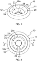
- FIGs. 1 to 3 are a perspective view, a plan view, and a side view of a female snap button 10 (in a snap button) according to an embodiment of the present invention.
- FIG. 4 is a cross-sectional view along line A-A in FIG. 2 .
- the female snap button 10 includes two members, i.e., a female snap body 11 made of metal having a substantially cuplike shape, and a ring member 20 made of soft resin which is accommodated in the female snap body 11.
- the ring member 20 can be flexibly and elastically deformed.
- the ring member 20 includes a cylindrical portion 21 that defines an engagement space 20a which detachably accepts an engaging protuberance 32 of a male snap button 30, which will be described later, an annular expansion upper portion 22 that expands outward from an upper edge of the cylindrical portion 21 in a radial direction, a ring bottom portion 23 that extends inward from a lower edge of the cylindrical portion 21 in the radial direction, and an annular protruding portion 24 that protrudes upward from an upper surface 22a of the expansion upper portion 22.
- the protruding portion 24 is continuous in a circumferential direction, but a plurality of protruding portions may be present at predetermined angular intervals in the circumferential direction.
- An annular slit 25 which is slightly recessed upward is present between a lower surface 22c of the expansion upper portion 22 and an outer peripheral surface of the cylindrical portion 21.
- a ring opening 26 for passing a shaft portion 41 of a button fastener 40 is provided in the center of the ring bottom portion 23.
- the cylindrical portion 21 has a female-side engagement edge 21a having the smallest inner diameter in the vicinity of an upper edge 21b thereof.
- the inner diameter of the cylindrical portion 21 slightly and gradually expands from the female-side engagement edge 21a to the lower edge of the cylindrical portion 21, and an inner peripheral surface of the cylindrical portion 21 on a lower side from the female-side engagement edge 21a is slightly inclined outward in the radial direction toward the lower edge.
- An inner peripheral surface of the cylindrical portion 21 on an upper side from the female-side engagement edge 21a is curved outward in the radial direction to the upper edge 21b of the cylindrical portion 21 which is a boundary with the protruding portion 24 in a substantially stepwise shape.
- the ring member 20 may not have the slit 25.
- the expansion upper portion 22 has the upper surface 22a, a peripheral side surface 22b, and the lower surface 22c and projects outward from the protruding portion 24 in the radial direction in a substantially rectangular cross section.
- a thickness between the upper and lower surfaces 22a and 22c of the expansion upper portion 22 is thicker than a thickness of the ring bottom portion 23 in the vertical direction or a thickness of the cylindrical portion 21 in the radial direction.
- An inner peripheral surface 24a of the protruding portion 24 is curved outward from a lower edge thereof (the upper edge 21b of the cylindrical portion 21) in the radial direction toward an upper edge thereof in a substantially stepwise shape and reaches a substantially horizontal top surface 24b of the protruding portion 24.
- An outer diameter of the protruding portion 24 is substantially constant from the lower edge thereof to the vicinity of the upper edge thereof, and an outer peripheral surface 24c of the protruding portion 24 is perpendicular to the upper surface 22a of the expansion upper portion 22. Further, the outer peripheral surface 24c and the top surface 24b of the protruding portion 24 are substantially perpendicular to each other, but a corner therebetween is rounded.
- a projecting height of the protruding portion 24 from the upper surface 22a of the expansion upper portion 22 is substantially the same as or slightly smaller than the thickness of the expansion upper portion 22 in the vertical direction.
- the upper surface 22a of the expansion upper portion 22 of the protruding portion 24 is located at substantially the same position as the upper edge 21b of the cylindrical portion 21 in the vertical direction.
- the female snap body 11 is formed using drawing processing and the like of a metal plate material and accommodates the ring member 20 to cover the ring member 20 from the outside in the radial direction and from below.
- the female snap body 11 includes a holding portion 12 that holds the expansion upper portion 22 of the ring member 20, a bottom portion 13 that supports the ring bottom portion 23 of the ring member 20 from below, and an annular connecting portion 14 that connects the holding portion 12 and the bottom portion 13.
- the holding portion 12 has an upper holding portion 12a, a peripheral side holding portion 12b, and a lower holding portion 12c.
- the upper holding portion 12a is an edge located at the uppermost side of the female snap body 11 (one side facing a male snap button 30).
- the radially inside edge of the upper holding portion 12a may be in contact with outer peripheral surface 24c of the protruding portion 24, or may be closer thereto or further separated therefrom than shown in the drawing.
- the protruding portion 24 of the ring member 20 projects above the upper holding portion 12a of the holding portion 12 located at the uppermost side in the female snap body 11.
- the projecting height is preferably 0.3 mm or more.
- the connecting portion 14 is inclined such that inner and outer diameters thereof are reduced downward and covers the cylindrical portion 21 of the ring member 20 with a slight gap. This gap can be eliminated by the outer peripheral surface of the cylindrical portion 21 expanding outward in the radial direction and coming into contact with the connecting portion 14 in a state in which an engaging protuberance 32 of a male snap button 30 is received in the cylindrical portion 21 (see FIG. 8 ).
- An opening 15 for passing a shaft portion 41 of the button fastener 40 is provided in the center of the bottom portion 13 to concentrically overlap the ring opening 26.
- a size of the ring opening 26 is substantially the same as or slightly smaller than a size of the opening 15 of the female snap body 11. Therefore, the ring bottom portion 23 covers substantially the entire upper surface of the bottom portion 13.
- FIG. 5 is a cross-sectional view showing the female snap button 10 when attached to fabric such as clothes using the button fastener 40, but the fabric is not shown.
- the shaft portion 41 of the button fastener 40 penetrates the fabric upward and then passes through the opening 15 of the female snap button 10 and the ring opening 26 to be received in the cylindrical portion 21, wherein the shaft portion 41 is crimped. Accordingly, the female snap button 10 is fixed to the fabric by the button fastener 40.
- the ring bottom portion 23 substantially covers the upper surface of the bottom portion 13, the shaft portion 41 is crimped to the ring bottom portion 23. In other words, the ring bottom portion 23 receives the crimped shaft portion 41.
- FIGs. 6 and 7 are a perspective view and a cross-sectional view of a male snap button 30 in the snap button according to an embodiment of the present invention.
- the male snap button 30 is formed using drawing processing and the like of a metal plate material and includes a disc-shaped base portion 31 and an engaging protuberance 32 that projects from the base portion 31.
- An opening 33 for passing the shaft portion 41 of the button fastener 40 is provided in the center of the base portion 31. That is, the male snap button 30 is also attached to the fabric by the button fastener 40.
- the engaging protuberance 32 includes an inner cylinder portion 32a, an outer cylinder portion 32b, and a connecting portion 32c that connects upper edges of the inner and outer connecting portions 32a and 32b in a convexly curved shape.
- a male-side engagement edge 32d having the largest outer diameter in the engaging protuberance 32 is provided in the vicinity of an upper edge of the outer cylinder portion 32b.
- the outer diameter of the male-side engagement edge 32d is slightly larger than that of the female-side engagement edge 21a of the female snap button 10. Further, a height from the base portion 31 to an apex of the engaging protuberance 32 is the same as a height from an upper surface of the ring bottom portion 23 of the ring member 20 to the top surface 24b of the protruding portion 24, or is slightly lower or higher than that height.
- a diameter of the base portion 31 of the male snap button 30 is slightly smaller than an outer diameter of the peripheral side holding portion 12b which is the maximum outer diameter of the female snap body 11 of the female snap button 10 and is substantially the same as an outer diameter of the expansion upper portion 22 of the ring member 20.
- FIG. 8 is a cross-sectional view showing the female snap button 10 and the male snap button 30 when engaged with each other.
- the female snap button 10 and the male snap button 30 are engaged with each other by the engaging protuberance 32 of the male snap button 30 being inserted into the cylindrical portion 21 of the ring member 20 of the female snap button 10, that is, the engagement space 20a, and the engagement is released by the engaging protuberance 32 being pulled out from the cylindrical portion 21.
- the female-side engagement edge 21a of the cylindrical portion 21 is temporarily expanded outward in the radial direction by the male-side engagement edge 32d of the engaging protuberance 32, and, when the male-side engagement edge 32d moves beyond the female-side engagement edge 21a in an axial direction, the female-side engagement edge 21a returns inward in the radial direction.
- the cylindrical portion 21 in which the engaging protuberance 32 is received is slightly expanded outward in the radial direction, and thus the cylindrical portion 21 comes into contact with the connecting portion 14 of the female snap body 11, or the gap between the cylindrical portion 21 and the connecting portion 14 is reduced.
- the slit 25 serves to promote the radially outward expansion of the cylindrical portion 21 in which the engaging protuberance 32 is received. Even without the slit 25, the ring member 20 made of soft resin can be elastically deformed in the radial direction.
- the base portion 31 of the male snap button 30 is in contact with the top surface 24b of the protruding portion 24 of the ring member 20 of the female snap button 10, but is separated from the upper holding portion 12a located at the uppermost side in the female snap body 11 by substantially the height of the protruding portion 24.
- the connecting portion 32c which is a top portion of the engaging protuberance 32 is barely in contact with or is adjacent to the upper surface of the ring bottom portion 23 of the ring member 20.
- the outer cylinder portion 32b of the engaging protuberance 32 accommodated in the cylindrical portion 21 is substantially in close contact with the inner peripheral surface of the cylindrical portion 21.
- the ring bottom portion 23 which is a soft resin portion is disposed between the engaging protuberance 32 and the bottom portion 13 of the female snap body 11.
- the male snap button 30 made of metal is in contact with only the ring member 20 made of soft resin of the female snap button 10, and is not in contact with the female snap body 11 made of metal of the female snap button 10.
- the engaging protuberance 32 of the male snap button 30 when the engaging protuberance 32 of the male snap button 30 is inserted into the cylindrical portion 21 of the ring member 20, that is, the engagement space 20a, the protruding portion 24 of the ring member 20 projects above the upper holding portion 12a located at the uppermost position in the female snap body 11, and thus the base portion 31 of the male snap button 30 comes into contact with the protruding portion 24 which is a soft resin portion, but does not come into contact with the female snap body 11 which is a metal portion. Further, when the engaging protuberance 32 is inserted into the engagement space 20a, the base portion 31 comes into contact with the protruding portion 24 to prevent further insertion.
- the connecting portion 32c of the engaging protuberance 32 which is a metal portion can come into contact with the ring bottom portion 23 which is a soft resin portion, but does not come into contact with the bottom portion 13 of the female snap body 11 which is a metal portion. Further, even when the engaging protuberance 32 is pulled out from the engagement space 20a, the male snap button 30 does not come into contact with the female snap body 11.
- the height of the protruding portion 24 is set such that when the engaging protuberance 32 is attached to and detached from the engagement space 20a, even if the male snap button 30 is tilted with respect to the female snap body 11 (even if an axis of the male snap button 30 deviates from an axis of the female snap body 11), the base portion 31 of the male snap button 30 does not come into contact with the female snap body 11.
- the ring member 20 does not have the ring bottom portion 23, when the engaging protuberance 32 of the male snap button 30 is attached to and detached from the engagement space 20a, that is, when the engaging protuberance 32 snaps into the female-side engagement edge 21a of the ring member 20, the behavior (or the displacement) of the ring member 20 becomes larger than that when the ring bottom portion 23 is present, which can lead to generation of a slight attaching/detaching sound.
- the ring member 20 since the ring member 20 has the ring bottom portion 23, the behavior of the ring member 20 at the time of attachment/detachment can be suppressed, and the attaching/detaching sound also can be reduced. As shown in FIG.
- the ring bottom portion 23 is fixed to the bottom portion 13 of the female snap body 11 by the shaft portion 41 of the button fastener 40. Therefore, the behavior of the ring member 20 at the time of attachment/detachment described above can be further suppressed, and the quietness at the time of attachment/detachment can be enhanced. From the above, in the snap button according to the present embodiment, there is no or little possibility that the male snap button 30 made of metal and the female snap body 11 made of metal come into contact with each other to generate an attaching/detaching sound.
- FIG. 9 is a cross-sectional view, similar to FIG. 5 , showing a modification example of the ring member.
- the ring member 120 shown in FIG. 9 includes a ring bottom portion 123.
- a length of the ring bottom portion 123 extending inward from the cylindrical portion 21 in the radial direction is shorter than that of the ring bottom portion 23 described above, and to that extent, a diameter of a ring opening 126 at the center of the ring bottom portion 123 is also larger than that of the ring opening 26 described above.
- the ring opening 126 is large, the bottom portion 13 of the female snap body is partially exposed from the ring opening 126 to the engagement space 20a side, and in the present example, the shaft portion 41 of the button fastener 40 is crimped to the exposed portion of the bottom portion 13.
- the ring bottom portion 123 covers the entire upper surface of the bottom portion 13 except for a portion corresponding to the crimped shaft portion 41 in the bottom portion 13. Further, in the engaged state of the male snap button 30 and the female snap button 10, the ring bottom portion 123 is disposed between the engaging protuberance 32 and the bottom portion 13 of the female snap body 11. Therefore, the engaging protuberance 32 does not come into contact with the bottom portion 13.
Landscapes
- Slide Fasteners, Snap Fasteners, And Hook Fasteners (AREA)
Abstract
Description
- The present invention relates to a snap button and female snap button, and particularly to a snap button constituted by a male snap button made of metal and a female snap button including a metal portion, and the female snap button in such a snap button.
- A snap button constituted by a pair of a male snap button and a female snap button which can engage with and disengage from each other is often used for clothing, bags, and the like. The engagement and disengagement of the snap button is performed by an engaging protuberance of the male snap button being attached to and detached from an engagement space of the female snap button. When the male snap button and the female snap button are attached to and detached from each other, an attaching/detaching sound occurs, and particularly in a case in which both the male and female snap buttons are made of a metal, the attaching/detaching sound becomes relatively loud.
- However, in clothing and the like used for hunting, bird watching, and the like, the above-described attaching/detaching sound of the snap button may hinder activity of a user.
- Therefore, an objective of the present invention is to provide a snap button and a female snap button with which it is possible for an attaching/detaching sound to be eliminated or reduced as much as possible.
- To solve the above problems, according to one aspect of the present invention, there is provided a snap button including a male snap button made of metal and a female snap button, wherein the male snap button includes a base portion, and an engaging protuberance which projects from the base portion, wherein the female snap button is provided with a ring member made of soft resin defining an engagement space which detachably accepts the engaging protuberance, and a female snap body made of metal accommodating the ring member, and wherein the ring member is provided with a protruding portion which projects further out to one side than an end on the one side of the female snap body facing the male snap button in an axial direction, and which is provided in a circumferential direction.
- In the present invention, the engagement and disengagement of the male snap button and the female snap button is performed by the engaging protuberance of the male snap button made of metal being attached to and detached from the engagement space of the ring member made of soft resin. Therefore, at the time of attachment/detachment, the metal engaging protuberance does not come into contact with the female snap body which is a metal portion of the female snap button, but comes into contact with only the ring member which is a soft resin portion. Further, when the engaging protuberance is inserted into the engagement space, since the protruding portion of the ring member projects further out to one side than an end furthest on the male snap button side (the one side) in the female snap body made of metal, the metal base portion can come into contact with the soft resin protruding portion, but the base portion of the male snap button does not come into contact with the female snap body made of metal. Therefore, even if the base portion which is a metal portion of the male snap button comes into contact with the protruding portion which is a soft resin portion of the female snap button when the engaging protuberance is inserted into the engagement space, the female snap body does not come into contact with the female snap body which is a metal portion of the female snap button. Therefore, in the snap button according to the present invention, an attaching/detaching sound does not occur at all or hardly occurs.
- In the present invention, a height of an end which projects further out to one side than an end on the one side of the female snap body facing the male snap button in the axial direction, that is, the protruding portion of the ring member from an end furthest on the male snap button side in the female snap body, projects on the one side can be set to a height at which the base portion does come into contact with the end including tilt of the male snap button with respect to the female snap button (deviation of both axes) at the time of attachment/detachment of the snap button, for example, to 0.3 mm or more. Further, in the present invention, examples of an aspect in which the protruding portion is provided in the ring member in the circumferential direction include an aspect in which the protruding portion is continuous in an annular shape in the circumferential direction and an aspect in which a plurality of protruding portions is provided at predetermined angular intervals in the circumferential direction.
- In the present invention, examples of the metal forming the male snap button and the female snap body include aluminum, an aluminum alloy, copper, a copper alloy, iron, and stainless steel, but the present invention is not limited thereto. Further, in the present invention, examples of the soft resin forming the ring member of the female snap button include elastomer resins such as a polyurethane-based resin, a polyester-based resin, a polyamide-based resin, an acrylic-based resin, a silicone-based resin, a polystyrene-based resin, a styrene-butadiene-based resin, and a nitrile butadiene-based resin, but the present invention is not limited thereto.
- In one embodiment of the present invention, the female snap body includes a bottom portion, and the ring member includes a ring bottom portion which is disposed between the bottom portion and the engaging protuberance in a state in which the engaging protuberance is accepted in the engagement space. In this case, when the engaging protuberance of the male snap button is inserted into the engagement space of the female snap button, the metal engaging protuberance does not come into contact with the metal bottom portion of the female snap button.
- In one embodiment of the present invention, in a state in which the engaging protuberance of the male snap button is accepted in the engagement space of the female snap button, the base portion of the male snap button is in contact with the protruding portion. In this case, when the engaging protuberance of the male snap button is inserted into the engagement space of the female snap button, the base portion of the male snap button comes into contact with the protruding portion of the female snap button, and thus further insertion of the engaging protuberance into the engagement space is prevented. In a state in which the base portion is in contact with the protruding portion of the female snap button in this way, the engaging protuberance can be in contact with or adjacent to the ring bottom portion of the ring member of the female snap button, but is not in contact with the metal bottom portion of the female snap body.
- In one embodiment of the present invention, the bottom portion and the ring bottom portion each have an opening through which a shaft portion of a button fastener passes, and the shaft portion is crimped to the bottom portion or the ring bottom portion. In this case, the attachment of the female snap button to the fabric such as clothes is performed by the shaft portion of the button fastener penetrating the fabric (the shaft portion of the button fastener may pass through a hole provided in advance in the fabric), the shaft portion subsequently passing through the opening of the bottom portion of the female snap body and the opening of the ring bottom portion of the ring member (a ring opening), and then the shaft portion being crimped. The crimping of the shaft portion can be performed on the ring bottom portion as shown in
FIG. 5 , or can be performed on the bottom portion of the female snap body as shown inFIG. 9 . - According to another aspect of the present invention, there is provided a female snap button including a ring member made of soft resin defining an engagement space, and a female snap body made of metal accommodating the ring member, wherein the ring member is provided with a protruding portion which projects further out to one side than an end on the one side of the female snap body facing a male snap button in an axial direction, and which is provided in a circumferential direction. The female snap button according to another aspect of the present invention substantially corresponds to the female snap button in the snap button according to the one aspect of the present invention described above.
- In one embodiment of the present invention, the female snap body includes a bottom portion, and the ring member includes a ring bottom portion which covers the bottom portion. In this case, since the ring bottom portion covers the bottom portion of the female snap body, when the engaging protuberance of the male snap button is accepted into the engagement space of the female snap button, the metal engaging protuberance can come into contact with the soft resin ring bottom portion, but does not come into contact with the metal bottom portion.
- In the present invention, when the engaging protuberance of the male snap button is attached to and detached from the engagement space of the ring member of the female snap button, the metal engaging protuberance does not come into contact with the female snap body which is a metal portion of the female snap button, but comes into contact with only the ring member which is a soft resin portion. Further, when the engaging protuberance is accepted into the engagement space, since the protruding portion of the ring member projects further out to one side than an end furthest on the male snap button side in the female snap body made of metal, the metal base portion of the male snap button can come into contact with the soft resin protruding portion, but does not come into contact with the female snap body made of metal. Therefore, it is possible for an attaching/detaching sound to be eliminated or reduced as much as possible.
-
-
FIG. 1 is a perspective view of a female snap button according to a first embodiment of the present invention. -
FIG. 2 is a plan view of the female snap button inFIG. 1 . -
FIG. 3 is a side view of the female snap button inFIG. 1 . -
FIG. 4 is a cross-sectional view along line A-A inFIG. 2 . -
FIG. 5 is a cross-sectional view showing the female snap button when attached to fabric (not shown) by a button fastener. -
FIG. 6 is a perspective view of a male snap button. -
FIG. 7 is a cross-sectional view of the male snap button. -
FIG. 8 is a cross-sectional view showing the female snap button and the male snap button when engaged with each other. -
FIG. 9 is a cross-sectional view, similar toFIG. 5 , showing a modification example of a ring member. - Hereinafter, preferable embodiments of the present invention will be described, but the present invention is not limited to such embodiments and can be appropriately modified within the scope of claims and the equivalent thereof.
-
FIGs. 1 to 3 are a perspective view, a plan view, and a side view of a female snap button 10 (in a snap button) according to an embodiment of the present invention.FIG. 4 is a cross-sectional view along line A-A inFIG. 2 . Thefemale snap button 10 includes two members, i.e., afemale snap body 11 made of metal having a substantially cuplike shape, and aring member 20 made of soft resin which is accommodated in thefemale snap body 11. Thering member 20 can be flexibly and elastically deformed. - Hereinafter, an example of the
female snap body 11 and thering member 20 will be described with reference to the drawings, and in this description, a vertical direction is based on a paper surface ofFIG. 4 . Thering member 20 includes acylindrical portion 21 that defines anengagement space 20a which detachably accepts anengaging protuberance 32 of amale snap button 30, which will be described later, an annular expansionupper portion 22 that expands outward from an upper edge of thecylindrical portion 21 in a radial direction, aring bottom portion 23 that extends inward from a lower edge of thecylindrical portion 21 in the radial direction, and anannular protruding portion 24 that protrudes upward from anupper surface 22a of the expansionupper portion 22. In the present embodiment, theprotruding portion 24 is continuous in a circumferential direction, but a plurality of protruding portions may be present at predetermined angular intervals in the circumferential direction. An annular slit 25 which is slightly recessed upward is present between alower surface 22c of the expansionupper portion 22 and an outer peripheral surface of thecylindrical portion 21. Further, a ring opening 26 for passing ashaft portion 41 of a button fastener 40 (seeFIG. 5 ) is provided in the center of thering bottom portion 23. - The
cylindrical portion 21 has a female-side engagement edge 21a having the smallest inner diameter in the vicinity of anupper edge 21b thereof. The inner diameter of thecylindrical portion 21 slightly and gradually expands from the female-side engagement edge 21a to the lower edge of thecylindrical portion 21, and an inner peripheral surface of thecylindrical portion 21 on a lower side from the female-side engagement edge 21a is slightly inclined outward in the radial direction toward the lower edge. An inner peripheral surface of thecylindrical portion 21 on an upper side from the female-side engagement edge 21a is curved outward in the radial direction to theupper edge 21b of thecylindrical portion 21 which is a boundary with theprotruding portion 24 in a substantially stepwise shape. An outer diameter of thecylindrical portion 21 on a lower side from the slit 25 slightly and gradually decreases downward. Therefore, a thickness in the radial direction of a portion of thecylindrical portion 21 on the lower side from the slit 25 becomes thinner downward. Although not shown, thering member 20 may not have the slit 25. - The expansion
upper portion 22 has theupper surface 22a, aperipheral side surface 22b, and thelower surface 22c and projects outward from the protrudingportion 24 in the radial direction in a substantially rectangular cross section. A thickness between the upper andlower surfaces upper portion 22 is thicker than a thickness of thering bottom portion 23 in the vertical direction or a thickness of thecylindrical portion 21 in the radial direction. An innerperipheral surface 24a of the protrudingportion 24 is curved outward from a lower edge thereof (theupper edge 21b of the cylindrical portion 21) in the radial direction toward an upper edge thereof in a substantially stepwise shape and reaches a substantially horizontaltop surface 24b of the protrudingportion 24. An outer diameter of the protrudingportion 24 is substantially constant from the lower edge thereof to the vicinity of the upper edge thereof, and an outerperipheral surface 24c of the protrudingportion 24 is perpendicular to theupper surface 22a of the expansionupper portion 22. Further, the outerperipheral surface 24c and thetop surface 24b of the protrudingportion 24 are substantially perpendicular to each other, but a corner therebetween is rounded. A projecting height of the protrudingportion 24 from theupper surface 22a of the expansionupper portion 22 is substantially the same as or slightly smaller than the thickness of the expansionupper portion 22 in the vertical direction. Theupper surface 22a of the expansionupper portion 22 of the protrudingportion 24 is located at substantially the same position as theupper edge 21b of thecylindrical portion 21 in the vertical direction. - The
female snap body 11 is formed using drawing processing and the like of a metal plate material and accommodates thering member 20 to cover thering member 20 from the outside in the radial direction and from below. Thefemale snap body 11 includes a holdingportion 12 that holds the expansionupper portion 22 of thering member 20, abottom portion 13 that supports thering bottom portion 23 of thering member 20 from below, and an annular connectingportion 14 that connects the holdingportion 12 and thebottom portion 13. The holdingportion 12 has anupper holding portion 12a, a peripheralside holding portion 12b, and alower holding portion 12c. Theupper holding portion 12a is an edge located at the uppermost side of the female snap body 11 (one side facing a male snap button 30). An outside portion of the expansionupper portion 22 of thering member 20 in the radial direction is received and held between theupper holding portion 12a and thelower holding portion 12c. In this state, a slight gap is present between theperipheral side surface 22b of the expansionupper portion 22 and the peripheralside holding portion 12b. Further, thelower surface 22c except for the vicinity of the slit 25 of the expansionupper portion 22 is supported in contact with thelower holding portion 12c. Theupper holding portion 12a is terminated in the vicinity of the protrudingportion 24 in theupper surface 22a of the expansionupper portion 22, and a radially inside edge of theupper holding portion 12a is slightly separated from the outerperipheral surface 24c of the protrudingportion 24. Although not shown, the radially inside edge of theupper holding portion 12a may be in contact with outerperipheral surface 24c of the protrudingportion 24, or may be closer thereto or further separated therefrom than shown in the drawing. The protrudingportion 24 of thering member 20 projects above theupper holding portion 12a of the holdingportion 12 located at the uppermost side in thefemale snap body 11. The projecting height is preferably 0.3 mm or more. - The connecting
portion 14 is inclined such that inner and outer diameters thereof are reduced downward and covers thecylindrical portion 21 of thering member 20 with a slight gap. This gap can be eliminated by the outer peripheral surface of thecylindrical portion 21 expanding outward in the radial direction and coming into contact with the connectingportion 14 in a state in which an engagingprotuberance 32 of amale snap button 30 is received in the cylindrical portion 21 (seeFIG. 8 ). Anopening 15 for passing ashaft portion 41 of the button fastener 40 (seeFIG. 5 ) is provided in the center of thebottom portion 13 to concentrically overlap thering opening 26. In the present embodiment, a size of thering opening 26 is substantially the same as or slightly smaller than a size of theopening 15 of thefemale snap body 11. Therefore, thering bottom portion 23 covers substantially the entire upper surface of thebottom portion 13. -
FIG. 5 is a cross-sectional view showing thefemale snap button 10 when attached to fabric such as clothes using thebutton fastener 40, but the fabric is not shown. In a case in which thefemale snap button 10 is attached to the fabric, theshaft portion 41 of thebutton fastener 40 penetrates the fabric upward and then passes through theopening 15 of thefemale snap button 10 and the ring opening 26 to be received in thecylindrical portion 21, wherein theshaft portion 41 is crimped. Accordingly, thefemale snap button 10 is fixed to the fabric by thebutton fastener 40. In the present embodiment, since thering bottom portion 23 substantially covers the upper surface of thebottom portion 13, theshaft portion 41 is crimped to thering bottom portion 23. In other words, thering bottom portion 23 receives the crimpedshaft portion 41. -
FIGs. 6 and7 are a perspective view and a cross-sectional view of amale snap button 30 in the snap button according to an embodiment of the present invention. Themale snap button 30 is formed using drawing processing and the like of a metal plate material and includes a disc-shapedbase portion 31 and an engagingprotuberance 32 that projects from thebase portion 31. Anopening 33 for passing theshaft portion 41 of thebutton fastener 40 is provided in the center of thebase portion 31. That is, themale snap button 30 is also attached to the fabric by thebutton fastener 40. The engagingprotuberance 32 includes aninner cylinder portion 32a, anouter cylinder portion 32b, and a connectingportion 32c that connects upper edges of the inner and outer connectingportions side engagement edge 32d having the largest outer diameter in the engagingprotuberance 32 is provided in the vicinity of an upper edge of theouter cylinder portion 32b. - The outer diameter of the male-
side engagement edge 32d is slightly larger than that of the female-side engagement edge 21a of thefemale snap button 10. Further, a height from thebase portion 31 to an apex of the engagingprotuberance 32 is the same as a height from an upper surface of thering bottom portion 23 of thering member 20 to thetop surface 24b of the protrudingportion 24, or is slightly lower or higher than that height. A diameter of thebase portion 31 of themale snap button 30 is slightly smaller than an outer diameter of the peripheralside holding portion 12b which is the maximum outer diameter of thefemale snap body 11 of thefemale snap button 10 and is substantially the same as an outer diameter of the expansionupper portion 22 of thering member 20. -
FIG. 8 is a cross-sectional view showing thefemale snap button 10 and themale snap button 30 when engaged with each other. Thefemale snap button 10 and themale snap button 30 are engaged with each other by the engagingprotuberance 32 of themale snap button 30 being inserted into thecylindrical portion 21 of thering member 20 of thefemale snap button 10, that is, theengagement space 20a, and the engagement is released by the engagingprotuberance 32 being pulled out from thecylindrical portion 21. When the engagingprotuberance 32 is attached to and detached from theengagement space 20a, the female-side engagement edge 21a of thecylindrical portion 21 is temporarily expanded outward in the radial direction by the male-side engagement edge 32d of the engagingprotuberance 32, and, when the male-side engagement edge 32d moves beyond the female-side engagement edge 21a in an axial direction, the female-side engagement edge 21a returns inward in the radial direction. Thecylindrical portion 21 in which the engagingprotuberance 32 is received is slightly expanded outward in the radial direction, and thus thecylindrical portion 21 comes into contact with the connectingportion 14 of thefemale snap body 11, or the gap between thecylindrical portion 21 and the connectingportion 14 is reduced. The slit 25 serves to promote the radially outward expansion of thecylindrical portion 21 in which the engagingprotuberance 32 is received. Even without the slit 25, thering member 20 made of soft resin can be elastically deformed in the radial direction. - In the engaged state of
FIG. 8 , thebase portion 31 of themale snap button 30 is in contact with thetop surface 24b of the protrudingportion 24 of thering member 20 of thefemale snap button 10, but is separated from theupper holding portion 12a located at the uppermost side in thefemale snap body 11 by substantially the height of the protrudingportion 24. Further, in the engaged state, the connectingportion 32c which is a top portion of the engagingprotuberance 32 is barely in contact with or is adjacent to the upper surface of thering bottom portion 23 of thering member 20. Further, theouter cylinder portion 32b of the engagingprotuberance 32 accommodated in thecylindrical portion 21 is substantially in close contact with the inner peripheral surface of thecylindrical portion 21. Furthermore, in the engaged state, thering bottom portion 23 which is a soft resin portion is disposed between the engagingprotuberance 32 and thebottom portion 13 of thefemale snap body 11. As described above, in the engaged state, themale snap button 30 made of metal is in contact with only thering member 20 made of soft resin of thefemale snap button 10, and is not in contact with thefemale snap body 11 made of metal of thefemale snap button 10. - Further, when the engaging
protuberance 32 of themale snap button 30 is inserted into thecylindrical portion 21 of thering member 20, that is, theengagement space 20a, the protrudingportion 24 of thering member 20 projects above theupper holding portion 12a located at the uppermost position in thefemale snap body 11, and thus thebase portion 31 of themale snap button 30 comes into contact with the protrudingportion 24 which is a soft resin portion, but does not come into contact with thefemale snap body 11 which is a metal portion. Further, when the engagingprotuberance 32 is inserted into theengagement space 20a, thebase portion 31 comes into contact with the protrudingportion 24 to prevent further insertion. At this time, the connectingportion 32c of the engagingprotuberance 32 which is a metal portion can come into contact with thering bottom portion 23 which is a soft resin portion, but does not come into contact with thebottom portion 13 of thefemale snap body 11 which is a metal portion. Further, even when the engagingprotuberance 32 is pulled out from theengagement space 20a, themale snap button 30 does not come into contact with thefemale snap body 11. The height of the protrudingportion 24 is set such that when the engagingprotuberance 32 is attached to and detached from theengagement space 20a, even if themale snap button 30 is tilted with respect to the female snap body 11 (even if an axis of themale snap button 30 deviates from an axis of the female snap body 11), thebase portion 31 of themale snap button 30 does not come into contact with thefemale snap body 11. Further, if thering member 20 does not have thering bottom portion 23, when the engagingprotuberance 32 of themale snap button 30 is attached to and detached from theengagement space 20a, that is, when the engagingprotuberance 32 snaps into the female-side engagement edge 21a of thering member 20, the behavior (or the displacement) of thering member 20 becomes larger than that when thering bottom portion 23 is present, which can lead to generation of a slight attaching/detaching sound. In the present embodiment, since thering member 20 has thering bottom portion 23, the behavior of thering member 20 at the time of attachment/detachment can be suppressed, and the attaching/detaching sound also can be reduced. As shown inFIG. 5 , thering bottom portion 23 is fixed to thebottom portion 13 of thefemale snap body 11 by theshaft portion 41 of thebutton fastener 40. Therefore, the behavior of thering member 20 at the time of attachment/detachment described above can be further suppressed, and the quietness at the time of attachment/detachment can be enhanced. From the above, in the snap button according to the present embodiment, there is no or little possibility that themale snap button 30 made of metal and thefemale snap body 11 made of metal come into contact with each other to generate an attaching/detaching sound. -
FIG. 9 is a cross-sectional view, similar toFIG. 5 , showing a modification example of the ring member. Thering member 120 shown inFIG. 9 includes aring bottom portion 123. A length of thering bottom portion 123 extending inward from thecylindrical portion 21 in the radial direction is shorter than that of thering bottom portion 23 described above, and to that extent, a diameter of aring opening 126 at the center of thering bottom portion 123 is also larger than that of the ring opening 26 described above. Since thering opening 126 is large, thebottom portion 13 of the female snap body is partially exposed from thering opening 126 to theengagement space 20a side, and in the present example, theshaft portion 41 of thebutton fastener 40 is crimped to the exposed portion of thebottom portion 13. Thering bottom portion 123 covers the entire upper surface of thebottom portion 13 except for a portion corresponding to the crimpedshaft portion 41 in thebottom portion 13. Further, in the engaged state of themale snap button 30 and thefemale snap button 10, thering bottom portion 123 is disposed between the engagingprotuberance 32 and thebottom portion 13 of thefemale snap body 11. Therefore, the engagingprotuberance 32 does not come into contact with thebottom portion 13. -
- 10
- Female snap button
- 11
- Female snap body
- 12
- Holding portion
- 12a
- Upper holding portion (end on one side)
- 13
- Bottom portion
- 15
- Opening
- 20, 120
- Ring member
- 20a
- Engagement space
- 21
- Cylindrical portion
- 22
- Expansion upper portion
- 23, 123
- Ring bottom portion
- 26, 126
- Ring opening
- 30
- Male snap button
- 31
- Base portion
- 32
- Engaging protuberance
- 40
- Button fastener
- 41
- Shaft portion
Claims (6)
- A snap button characterized in that comprising:a male snap button (30) made of metal; anda female snap button (10),wherein the male snap button (30) comprises:a base portion (31), andan engaging protuberance (32) which projects from the base portion (31), wherein the female snap button (10) comprises:a ring member (20, 120) made of soft resin, defining an engagement space (20a) which detachably accepts the engaging protuberance (32), anda female snap body (11) made of metal, accommodating the ring member (20, 120), andwherein the ring member (20, 120) is provided with a protruding portion (24) which projects further out to one side than an end (12a) on the one side of the female snap body (11) facing the male snap button (30) in an axial direction, and which is provided in a circumferential direction.
- The snap button according to claim 1, whereinthe female snap body (11) comprises a bottom portion (13), andthe ring member (20, 120) comprises a ring bottom portion (23, 123) which is disposed between the bottom portion (13) and the engaging protuberance (32) in a state in which the engaging protuberance (32) is accepted in the engagement space (20a).
- The snap button according to claim 1 or 2, wherein
in a state in which the engaging protuberance (32) of the male snap button (30) is accepted in the engagement space (20a) of the female snap button (10), the base portion (31) of the male snap button (30) is in contact with the protruding portion (24). - The snap button according to claim 2, whereinthe bottom portion (13) and the ring bottom portion (23, 123) each have an opening (15; 26, 126) through which a shaft portion (41) of a button fastener (40) passes, andthe shaft portion (41) is crimped to the bottom portion (13) or the ring bottom portion (23, 123).
- A female snap button characterized in that comprising:a ring member (20, 120) made of soft resin, defining an engagement space (20a); anda female snap body (11) made of metal, accommodating the ring member (20, 120),wherein the ring member (20, 120) is provided with a protruding portion (24) which projects further out to one side than an end (12a) on the one side of the female snap body (11) facing a male snap button (10) in an axial direction, and which is provided in a circumferential direction.
- The female snap button according to claim 5, whereinthe female snap body (11) comprises a bottom portion (13), andthe ring member (20) comprises a ring bottom portion (23, 123) which covers the bottom portion (13).
Applications Claiming Priority (1)
| Application Number | Priority Date | Filing Date | Title |
|---|---|---|---|
| PCT/JP2018/045178 WO2020115911A1 (en) | 2018-12-07 | 2018-12-07 | Snap button, and female snap button |
Publications (2)
| Publication Number | Publication Date |
|---|---|
| EP3892148A1 true EP3892148A1 (en) | 2021-10-13 |
| EP3892148A4 EP3892148A4 (en) | 2022-07-20 |
Family
ID=70974218
Family Applications (1)
| Application Number | Title | Priority Date | Filing Date |
|---|---|---|---|
| EP18942214.0A Withdrawn EP3892148A4 (en) | 2018-12-07 | 2018-12-07 | Snap button, and female snap button |
Country Status (6)
| Country | Link |
|---|---|
| US (1) | US11653724B2 (en) |
| EP (1) | EP3892148A4 (en) |
| JP (1) | JP7082685B2 (en) |
| CN (1) | CN113163905B (en) |
| TW (1) | TWI708575B (en) |
| WO (1) | WO2020115911A1 (en) |
Family Cites Families (10)
| Publication number | Priority date | Publication date | Assignee | Title |
|---|---|---|---|---|
| US3083430A (en) * | 1960-10-20 | 1963-04-02 | United Carr Fastener Corp | Metal and plastic socket |
| JPS55113403A (en) * | 1980-01-28 | 1980-09-02 | Kiyoshi Takeda | Button type hook |
| JPS61136915A (en) | 1984-12-04 | 1986-06-24 | Sumitomo Metal Mining Co Ltd | Production of granular silver oxide |
| JPS61136915U (en) * | 1985-02-15 | 1986-08-26 | ||
| JPS62111409U (en) * | 1985-12-28 | 1987-07-16 | ||
| DE102006045185A1 (en) * | 2006-09-25 | 2008-04-03 | Ykk Corporation | Matrix part of a push button |
| CN104135887B (en) * | 2012-02-15 | 2016-06-08 | Ykk株式会社 | Female snaps and snaps |
| TWI504357B (en) * | 2014-03-28 | 2015-10-21 | Button Int Co Ltd | Buckle |
| KR101981869B1 (en) * | 2014-12-01 | 2019-05-23 | 와이케이케이 가부시끼가이샤 | Upper structure of female snap fastener, female snap fastener, and method for attaching female snap fastener to material |
| US10130148B1 (en) * | 2017-11-30 | 2018-11-20 | Duraflex Hong Kong Limited | Snap button |
-
2018
- 2018-12-07 US US17/299,303 patent/US11653724B2/en active Active
- 2018-12-07 JP JP2020558793A patent/JP7082685B2/en active Active
- 2018-12-07 WO PCT/JP2018/045178 patent/WO2020115911A1/en not_active Ceased
- 2018-12-07 CN CN201880099921.4A patent/CN113163905B/en active Active
- 2018-12-07 EP EP18942214.0A patent/EP3892148A4/en not_active Withdrawn
-
2019
- 2019-05-16 TW TW108116845A patent/TWI708575B/en active
Also Published As
| Publication number | Publication date |
|---|---|
| EP3892148A4 (en) | 2022-07-20 |
| US11653724B2 (en) | 2023-05-23 |
| CN113163905B (en) | 2022-11-18 |
| US20220053889A1 (en) | 2022-02-24 |
| TWI708575B (en) | 2020-11-01 |
| JP7082685B2 (en) | 2022-06-08 |
| CN113163905A (en) | 2021-07-23 |
| WO2020115911A1 (en) | 2020-06-11 |
| JPWO2020115911A1 (en) | 2021-09-27 |
| TW202021498A (en) | 2020-06-16 |
Similar Documents
| Publication | Publication Date | Title |
|---|---|---|
| CN102639021B (en) | Button and upper die for attaching button | |
| US9309972B2 (en) | Hole plug | |
| US10278457B2 (en) | Female snap button | |
| JPS62283211A (en) | Washer of shielding material for roofing | |
| US10986901B2 (en) | Snap button | |
| US11653724B2 (en) | Snap button and female snap button | |
| US7703180B2 (en) | Pressure botton | |
| CN109890239B (en) | Convex part of snap fastener and snap fastener | |
| JP5808346B2 (en) | Eyelet installation method | |
| JP7716537B2 (en) | socket | |
| CN114641218B (en) | Button mounting parts | |
| CN210960574U (en) | Reinforced I-shaped buckle | |
| WO2025004363A1 (en) | Female snap button | |
| KR860001757Y1 (en) | Snap fastener socket | |
| CN112996409B (en) | Male button and female button | |
| TWI457086B (en) | Buttons and buttons for mounting | |
| HK1077718A1 (en) | Button |
Legal Events
| Date | Code | Title | Description |
|---|---|---|---|
| STAA | Information on the status of an ep patent application or granted ep patent |
Free format text: STATUS: THE INTERNATIONAL PUBLICATION HAS BEEN MADE |
|
| PUAI | Public reference made under article 153(3) epc to a published international application that has entered the european phase |
Free format text: ORIGINAL CODE: 0009012 |
|
| STAA | Information on the status of an ep patent application or granted ep patent |
Free format text: STATUS: REQUEST FOR EXAMINATION WAS MADE |
|
| 17P | Request for examination filed |
Effective date: 20210604 |
|
| AK | Designated contracting states |
Kind code of ref document: A1 Designated state(s): AL AT BE BG CH CY CZ DE DK EE ES FI FR GB GR HR HU IE IS IT LI LT LU LV MC MK MT NL NO PL PT RO RS SE SI SK SM TR |
|
| DAV | Request for validation of the european patent (deleted) | ||
| DAX | Request for extension of the european patent (deleted) | ||
| A4 | Supplementary search report drawn up and despatched |
Effective date: 20220615 |
|
| RIC1 | Information provided on ipc code assigned before grant |
Ipc: A44B 17/00 20060101AFI20220611BHEP |
|
| STAA | Information on the status of an ep patent application or granted ep patent |
Free format text: STATUS: EXAMINATION IS IN PROGRESS |
|
| 17Q | First examination report despatched |
Effective date: 20230830 |
|
| STAA | Information on the status of an ep patent application or granted ep patent |
Free format text: STATUS: THE APPLICATION IS DEEMED TO BE WITHDRAWN |
|
| 18D | Application deemed to be withdrawn |
Effective date: 20240611 |