EP3891406B1 - Push-on fastener, assembly, and method of making and using the same - Google Patents
Push-on fastener, assembly, and method of making and using the same Download PDFInfo
- Publication number
- EP3891406B1 EP3891406B1 EP19817615.8A EP19817615A EP3891406B1 EP 3891406 B1 EP3891406 B1 EP 3891406B1 EP 19817615 A EP19817615 A EP 19817615A EP 3891406 B1 EP3891406 B1 EP 3891406B1
- Authority
- EP
- European Patent Office
- Prior art keywords
- push
- fastener
- radial
- low friction
- annular base
- Prior art date
- Legal status (The legal status is an assumption and is not a legal conclusion. Google has not performed a legal analysis and makes no representation as to the accuracy of the status listed.)
- Active
Links
Images


Classifications
-
- F—MECHANICAL ENGINEERING; LIGHTING; HEATING; WEAPONS; BLASTING
- F16—ENGINEERING ELEMENTS AND UNITS; GENERAL MEASURES FOR PRODUCING AND MAINTAINING EFFECTIVE FUNCTIONING OF MACHINES OR INSTALLATIONS; THERMAL INSULATION IN GENERAL
- F16B—DEVICES FOR FASTENING OR SECURING CONSTRUCTIONAL ELEMENTS OR MACHINE PARTS TOGETHER, e.g. NAILS, BOLTS, CIRCLIPS, CLAMPS, CLIPS OR WEDGES; JOINTS OR JOINTING
- F16B21/00—Means for preventing relative axial movement of a pin, spigot, shaft or the like and a member surrounding it; Stud-and-socket releasable fastenings
- F16B21/10—Means for preventing relative axial movement of a pin, spigot, shaft or the like and a member surrounding it; Stud-and-socket releasable fastenings by separate parts
- F16B21/16—Means for preventing relative axial movement of a pin, spigot, shaft or the like and a member surrounding it; Stud-and-socket releasable fastenings by separate parts with grooves or notches in the pin or shaft
- F16B21/18—Means for preventing relative axial movement of a pin, spigot, shaft or the like and a member surrounding it; Stud-and-socket releasable fastenings by separate parts with grooves or notches in the pin or shaft with circlips or like resilient retaining devices, i.e. resilient in the plane of the ring or the like; Details
- F16B21/186—Means for preventing relative axial movement of a pin, spigot, shaft or the like and a member surrounding it; Stud-and-socket releasable fastenings by separate parts with grooves or notches in the pin or shaft with circlips or like resilient retaining devices, i.e. resilient in the plane of the ring or the like; Details external, i.e. with contracting action
-
- F—MECHANICAL ENGINEERING; LIGHTING; HEATING; WEAPONS; BLASTING
- F16—ENGINEERING ELEMENTS AND UNITS; GENERAL MEASURES FOR PRODUCING AND MAINTAINING EFFECTIVE FUNCTIONING OF MACHINES OR INSTALLATIONS; THERMAL INSULATION IN GENERAL
- F16B—DEVICES FOR FASTENING OR SECURING CONSTRUCTIONAL ELEMENTS OR MACHINE PARTS TOGETHER, e.g. NAILS, BOLTS, CIRCLIPS, CLAMPS, CLIPS OR WEDGES; JOINTS OR JOINTING
- F16B21/00—Means for preventing relative axial movement of a pin, spigot, shaft or the like and a member surrounding it; Stud-and-socket releasable fastenings
- F16B21/10—Means for preventing relative axial movement of a pin, spigot, shaft or the like and a member surrounding it; Stud-and-socket releasable fastenings by separate parts
- F16B21/20—Means for preventing relative axial movement of a pin, spigot, shaft or the like and a member surrounding it; Stud-and-socket releasable fastenings by separate parts for bolts or shafts without holes, grooves, or notches for locking members
-
- F—MECHANICAL ENGINEERING; LIGHTING; HEATING; WEAPONS; BLASTING
- F16—ENGINEERING ELEMENTS AND UNITS; GENERAL MEASURES FOR PRODUCING AND MAINTAINING EFFECTIVE FUNCTIONING OF MACHINES OR INSTALLATIONS; THERMAL INSULATION IN GENERAL
- F16B—DEVICES FOR FASTENING OR SECURING CONSTRUCTIONAL ELEMENTS OR MACHINE PARTS TOGETHER, e.g. NAILS, BOLTS, CIRCLIPS, CLAMPS, CLIPS OR WEDGES; JOINTS OR JOINTING
- F16B37/00—Nuts or like thread-engaging members
- F16B37/08—Quickly-detachable or mountable nuts, e.g. consisting of two or more parts; Nuts movable along the bolt after tilting the nut
- F16B37/0807—Nuts engaged from the end of the bolt, e.g. axially slidable nuts
- F16B37/0842—Nuts engaged from the end of the bolt, e.g. axially slidable nuts fastened to the threaded bolt with snap-on-action, e.g. push-on nuts for stud bolts
-
- F—MECHANICAL ENGINEERING; LIGHTING; HEATING; WEAPONS; BLASTING
- F16—ENGINEERING ELEMENTS AND UNITS; GENERAL MEASURES FOR PRODUCING AND MAINTAINING EFFECTIVE FUNCTIONING OF MACHINES OR INSTALLATIONS; THERMAL INSULATION IN GENERAL
- F16B—DEVICES FOR FASTENING OR SECURING CONSTRUCTIONAL ELEMENTS OR MACHINE PARTS TOGETHER, e.g. NAILS, BOLTS, CIRCLIPS, CLAMPS, CLIPS OR WEDGES; JOINTS OR JOINTING
- F16B2200/00—Constructional details of connections not covered for in other groups of this subclass
- F16B2200/79—Friction-reducing coatings
-
- F—MECHANICAL ENGINEERING; LIGHTING; HEATING; WEAPONS; BLASTING
- F16—ENGINEERING ELEMENTS AND UNITS; GENERAL MEASURES FOR PRODUCING AND MAINTAINING EFFECTIVE FUNCTIONING OF MACHINES OR INSTALLATIONS; THERMAL INSULATION IN GENERAL
- F16B—DEVICES FOR FASTENING OR SECURING CONSTRUCTIONAL ELEMENTS OR MACHINE PARTS TOGETHER, e.g. NAILS, BOLTS, CIRCLIPS, CLAMPS, CLIPS OR WEDGES; JOINTS OR JOINTING
- F16B33/00—Features common to bolt and nut
- F16B33/008—Corrosion preventing means
Definitions
- the present disclosure relates to push-on fasteners, and more particularly to push-on fasteners installed on shafts or similar components.
- a push-on fastener may be disposed to distribute load of an inner member, e.g., a shaft in an assembly or mechanism. Specific types of push-on fasteners may be used to axially fix itself to an inner member and interact with another component of the assembly.
- the inner member may be rotating during usage where the push-on fastener may move against the side of other components of the assembly, such as an outer member, which may cause friction, vibration, and noise.
- an outer member which may cause friction, vibration, and noise.
- WO95/20108A1 discloses a retainer clip and shaft combination for axially securing an apertured mechanical element on the shaft.
- FIG. 9C includes a perspective view of a push-on fastener in accordance with an embodiment.
- Embodiments described herein are generally directed to a push-on fastener and methods of creating and using a push-on fastener within an assembly.
- the push-on fastener has an annular base and a plurality of radial tabs extending from the annular base.
- the radial tabs provide at least one peripheral surface that is free of low friction layer.
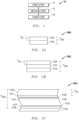
- FIG. 1 includes a diagram showing a forming process 10 for forming a push-on fastener.
- the forming process 10 may include a first step 12 of providing a base material, a second step 14 of coating the base material with a low friction coating to form a composite material and a third step 16 of forming the composite material into a push-on fastener.
- the base material may be a substrate.
- the substrate can at least partially include a metal.
- the metal may include iron, copper, titanium, tin, aluminum, alloys thereof, or may be another type of material.
- the substrate can at least partially include a steel, such as, a stainless steel, carbon steel, or spring steel.
- the substrate can at least partially include a 301 stainless steel.
- the 301 stainless steel may be annealed, 1 ⁇ 4 hard, 1 ⁇ 2 hard, 3 ⁇ 4 hard, or full hard.
- the substrate may include a woven mesh or an expanded metal grid.
- the woven mesh can be a woven polymer mesh.
- the substrate may not include a mesh or grid.
- FIG. 2A includes an illustration of the composite material 1000 that may be formed according to first step 12 and second step 14 of the forming process 10.
- FIG. 2A shows the layer by layer configuration of a composite material 1000 after second step 14.
- the composite material 1000 may include a substrate 1119 (i.e., the base material provided in the first step 12) and a low friction layer 1104 (i.e., the low friction coating applied in second step 14).
- the low friction layer 1104 can be coupled to at least a portion of the substrate 1119.
- the low friction layer 1104 can be coupled to a surface of the substrate 1119 so as to form a low friction interface with another surface of another component.
- the low friction layer 1104 can be coupled to the radially inner surface of the substrate 1119 so as to form a low friction interface with another surface of another component.
- the low friction layer 1104 can be coupled to the radially outer surface of the substrate 1119 so as to form a low friction interface with another surface of another component.
- the low friction layer 1104 can include a low friction material.
- Low friction materials may include, for example, for example, a polymer, such as a polyketone, a polyaramid, a polyimide, a polytherimide, a polyphenylene sulfide, a polyetherslfone, a polysulfone, a polypheylene sulfone, a polyamideimide, ultra high molecular weight polyethylene, a fluoropolymer, a polyamide, a polybenzimidazole, or any combination thereof.
- a polymer such as a polyketone, a polyaramid, a polyimide, a polytherimide, a polyphenylene sulfide, a polyetherslfone, a polysulfone, a polypheylene sulfone, a polyamideimide, ultra high molecular weight polyethylene, a fluoropolymer, a polyamide, a polybenzimi
- the low friction layer 1104 includes a polyketone, a polyaramid, a polyimide, a polyetherimide, a polyamideimide, a polyphenylene sulfide, a polyphenylene sulfone, a fluoropolymer, a polybenzimidazole, a derivation thereof, or a combination thereof.
- the low friction/wear resistant layer includes a polymer, such as a polyketone, a thermoplastic polyimide, a polyetherimide, a polyphenylene sulfide, a polyether sulfone, a polysulfone, a polyamideimide, a derivative thereof, or a combination thereof.
- the low friction/wear resistant layer includes polyketone, such as polyether ether ketone (PEEK), polyether ketone, polyether ketone ketone, polyether ketone ether ketone, a derivative thereof, or a combination thereof.
- the low friction/wear resistant layer may be an ultra high molecular weight polyethylene.
- An example fluoropolymer includes fluorinated ethylene propylene (FEP), polytetrafluoroethylene (PTFE), polyvinylidene fluoride (PVDF), perfluoroalkoxy (PFA), a terpolymer of tetrafluoroethylene, hexafluoropropylene, and vinylidene fluoride (THV), polychlorotrifluoroethylene (PCTFE), ethylene tetrafluoroethylene copolymer (ETFE), ethylene chlorotrifluoroethylene copolymer (ECTFE), polyacetal, polybutylene terephthalate (PBT), polyethylene terephthalate (PET), polyimide (PI), polyetherimide, polyetheretherketone (PEEK), polyethylene (PE), polysulfone, polyamide (PA), polyphenylene oxide, polyphenylene sulfide (PPS), polyurethane, polyester, liquid crystal polymers (LCP), or any combination thereof.
- the low friction layer 1104 may include a solid based material including lithium soap, graphite, boron nitride, molybdenum disulfide, tungsten disulfide, polytetrafluoroethylene, carbon nitride, tungsten carbide, or diamond like carbon, a metal (such as aluminum, zinc, copper, magnesium, tin, platinum, titanium, tungsten, lead, iron, bronze, steel, spring steel, stainless steel), a metal alloy (including the metals listed), an anodized metal (including the metals listed) or any combination thereof. Fluoropolymers may be used according to particular embodiments.
- a “low friction material” can be a material having a dry static coefficient of friction as measured against steel of less than 0.5, such as less than 0.4, less than 0.3, or even less than 0.2.
- a “high friction material” can be a material having a dry static coefficient of friction as measured against steel of greater than 0.6, such as greater than 0.7, greater than 0.8, greater than 0.9, or even greater than 1.0.
- the low friction layer 1104 may further include fillers, including glass fibers, carbon fibers, silicon, PEEK, aromatic polyester, carbon particles, bronze, fluoropolymers, thermoplastic fillers, aluminum oxide, polyamidimide (PAI), PPS, polyphenylene sulfone (PPSO2), LCP, aromatic polyesters, molybdenum disulfide, tungsten disulfide, graphite, grapheme, expanded graphite, boron nitride, talc, calcium fluoride, or any combination thereof.
- fillers including glass fibers, carbon fibers, silicon, PEEK, aromatic polyester, carbon particles, bronze, fluoropolymers, thermoplastic fillers, aluminum oxide, polyamidimide (PAI), PPS, polyphenylene sulfone (PPSO2), LCP, aromatic polyesters, molybdenum disulfide, tungsten disulfide, graphite, grapheme, expanded graphite, boron nitride, tal
- the filler can include alumina, silica, titanium dioxide, calcium fluoride, boron nitride, mica, Wollastonite, silicon carbide, silicon nitride, zirconia, carbon black, pigments, or any combination thereof.
- Fillers can be in the form of beads, fibers, powder, mesh, or any combination thereof.
- the low friction layer 1104 can have an axial height T FL in a range of 0.01 mm and 0.4 mm, such as in a range of 0.15 mm and 0.35 mm, or even in a range of 0.2 mm and 0.3 mm.
- the axial height of the low friction 1104 may be uniform, i.e., an axial height at a first location of the low friction layer 1104 can be equal to an axial height at a second location therealong.
- the low friction layer 1104 may overlie one major surface of the substrate 1119, shown, or overlie both major surfaces.
- the substrate 1119 may extend at least partially along a length of the composite material 1000.
- the substrate 1119 may be at least partially encapsulated by the low friction layer 1104.
- FIG. 2B includes an illustration of an alternative composite material that may be formed according to first step 12 and second step 14 of the forming process 10.
- FIG. 2B shows the layer by layer configuration of a composite material 1002 after second step 14.
- the composite material 1002 may be similar to the composite material 1000 of FIG. 2A , except this composite material 1002 may also include at least one adhesive layer 1121 that may couple the low friction layer 1104 to the substrate 1119 (i.e., the base material provided in the first step 12) and a low friction layer 1104 (i.e., the low friction coating applied in second step 14).
- the substrate 1119 as a solid component, woven mesh or expanded metal grid, may be embedded between at least one adhesive layer 1121 included between the low friction layer 1104 and the substrate 1119.
- the adhesive layer 1121 may include any known adhesive material common to the fastener arts including, but not limited to, fluoropolymers, epoxy resins, polyimide resins, polyether/polyamide copolymers, ethylene vinyl acetates, ethylene tetrafluoroethylene (ETFE), ETFE copolymer, perfluoroalkoxy (PFA), or any combination thereof.
- the adhesive can include a copolymer.
- the hot melt adhesive can have a melting temperature of not greater than 250°C, such as not greater than 220°C. In another example, the adhesive may break down above 200°C, such as above 220°C. In further examples, the melting temperature of the hot melt adhesive can be higher than 250°C or even higher than 300°C.
- the adhesive layer 1121 can have an axial height of about 1 to 50 microns, such as about 7 to 15 microns.
- FIG. 2C includes an illustration of an alternative composite material that may be formed according to first step 12 and second step 14 of the forming process 10.
- FIG. 2C shows the layer by layer configuration of a composite material 1003 after second step 14.
- the composite material 1003 may be similar to the composite material 1002 of FIG. 2B , except this composite material 1003 may also include at least one corrosion protection layer 1704, 1705, and 1708, and a corrosion resistant coating 1124 that can include an adhesion promoter layer 1127 and an epoxy layer 1129 that may couple to the substrate 1119 (i.e., the base material provided in the first step 12) and a low friction layer 1104 (i.e., the low friction coating applied in second step 14).
- the substrate 1119 may be coated with corrosion protection layers 1704 and 1705 to prevent corrosion of the composite material 1003 prior to processing. Additionally, a corrosion protection layer 1708 can be applied over layer 1704. Each of layers 1704, 1705, and 1708 can have an axial height of about 1 to 50 microns, such as about 7 to 15 microns. Layers 1704 and 1705 can include a phosphate of zinc, iron, manganese, or any combination thereof, or a nano-ceramic layer.
- layers 1704 and 1705 can include functional silanes, nano-scaled silane based primers, hydrolyzed silanes, organosilane adhesion promoters, solvent/water based silane primers, chlorinated polyolefins, passivated surfaces, commercially available zinc (mechanical/galvanic) or zinc-nickel coatings, or any combination thereof.
- Layer 1708 can include functional silanes, nano-scaled silane based primers, hydrolyzed silanes, organosilane adhesion promoters, solvent/water based silane primers. Corrosion protection layers 1704, 1706, and 1708 can be removed or retained during processing.
- the composite material 1003 may further include a corrosion resistant coating 1125.
- the corrosion resistant coating 1125 can have a axial height of about 1 to 50 microns, such as about 5 to 20 microns, and such as about 7 to 15 microns.
- the corrosion resistant coating 1125 can include an adhesion promoter layer 1127 and an epoxy layer 1129.
- the adhesion promoter layer 1127 can include a phosphate of zinc, iron, manganese, tin, or any combination thereof, or a nano-ceramic layer.
- the adhesion promoter layer 1127 can include functional silanes, nano-scaled silane based layers, hydrolyzed silanes, organosilane adhesion promoters, solvent/water based silane primers, chlorinated polyolefins, passivated surfaces, commercially available zinc (mechanical / galvanic) or Zinc-Nickel coatings, or any combination thereof.
- the epoxy layer 1129 can be a thermal cured epoxy, a UV cured epoxy, an IR cured epoxy, an electron beam cured epoxy, a radiation cured epoxy, or an air cured epoxy.
- the epoxy layer 1129 can include polyglycidylether, diglycidylether, bisphenol A, bisphenol F, oxirane, oxacyclopropane, ethylenoxide, 1,2-epoxypropane, 2-methyloxirane, 9,10-epoxy-9,10-dihydroanthracene, or any combination thereof.
- the epoxy layer 1129 can further include a hardening agent.
- the hardening agent can include amines, acid anhydrides, phenol novolac hardeners such as phenol novolac poly[N-(4-hydroxyphenyl)maleimide] (PHPMI), resole phenol formaldehydes, fatty amine compounds, polycarbonic anhydrides, polyacrylate, isocyanates, encapsulated polyisocyanates, boron trifluoride amine complexes, chromic-based hardeners, polyamides, or any combination thereof.
- Amines can include aliphatic amines such as monoethylamine, diethylenetriamine, triethylenetetraamine, and the like, alicyclic amines, aromatic amines such as cyclic aliphatic amines, cyclo aliphatic amines, amidoamines, polyamides, dicyandiamides, imidazole derivatives, and the like, or any combination thereof.
- aliphatic amines such as monoethylamine, diethylenetriamine, triethylenetetraamine, and the like
- aromatic amines such as cyclic aliphatic amines, cyclo aliphatic amines, amidoamines, polyamides, dicyandiamides, imidazole derivatives, and the like, or any combination thereof.
- any of the layers on the composite material 1000, 1002, 1003, as described above can each be disposed in a roll and peeled therefrom to join together under pressure, at elevated temperatures (hot or cold pressed or rolled), by an adhesive, or by any combination thereof.
- Any of the layers of the composite material 1000, as described above may be laminated together such that they at least partially overlap one another.
- Any of the layers on the composite material 1000, 1002, 1003, as described above may be applied together using coating technique, such as, for example, physical or vapor deposition, spraying, plating, powder coating, or through other chemical or electrochemical techniques.
- the low friction layer 1104 may be applied by a roll-to-roll coating process, including for example, extrusion coating.
- the low friction layer 1104 may be heated to a molten or semi-molten state and extruded through a slot die onto a major surface of the substrate 1119.
- the low friction layer 1104 may be cast or molded.
- any of the layers on the composite material 1000, 1002, 1003, as described above, may be applied by a coating technique, such as, for example, physical or vapor deposition, spraying, plating, powder coating, or through other chemical or electrochemical techniques.
- the low friction layer 1104 may be applied by a roll-to-roll coating process, including for example, extrusion coating.
- the low friction layer 1104 may be heated to a molten or semi-molten state and extruded through a slot die onto a major surface of the substrate 1119.
- the low friction layer 1104 may be cast or molded.
- forming the composite material 1000, 1002, 1003 into a push-on fastener may include a cutting operation.
- the cutting operation may include use of a stamp, press, punch, saw, or may be machined in a different way.
- the cutting operation may form a peripheral surface on the push-on fastener.
- the cutting operation may define a cutting direction initiated from a first major surface to a second major surface, opposite the first major surface, to form the peripheral surfaces or edges.
- the cutting operation may define a cutting direction initiated from the second major surface to the first major surface to form the peripheral surfaces or edges.
- FIGS. 3A-3D include an illustration showing a cutting operation to form a push on fastener 100.
- the push on fastener 100 has a first major surface 107 and a second major surface 109.
- the push-on fastener 100 further has an annular base 104.
- the push-on fastener 100 further includes at least one radial tab 110.
- the at least one radial tab 110 may include an inner radial edge 123.
- the at least one radial tab 110 may define a peripheral surface 112a.
- the at least one radial tab 110 may include an outer radial edge 125.
- the at least one radial tab 110 may define a peripheral surface 112b.
- the push-on fastener 100 may be cut by a cutting operation to form one of the peripheral surfaces 112a, 112b after the low friction layer 1104, 1104' is formed on the substrate 1119.
- Two low friction layers 1104, 1104' may be coupled to the substrate 1119.
- FIG. 3A shows an upward cutting direction against an angle ⁇ on a push-on fastener 100 with inwardly facing radial tabs 110.
- FIG. 3B shows a downward cutting direction toward the angle ⁇ on a push-on fastener 100 with inwardly facing radial tabs 110.
- FIG. 3C shows an upward cutting direction against the angle ⁇ on a push-on fastener 100 with outwardly facing radial tabs 110.
- FIG. 3D shows a downward cutting direction toward the angle ⁇ on a push-on fastener 100 with outwardly facing radial tabs 110.
- the cut may form an exposed surface 175 free of low friction layer 1104 on the push-on fastener 100.
- the cut may form an exposed surface 175 free of low friction layer 1104 on the inner radial edge 123 of the at least one radial tab 110 of the push-on fastener 100.
- FIGS. 3C shows an upward cutting direction against the angle ⁇ on a push-on fastener 100 with outwardly facing radial tabs 110.
- FIG. 3D shows a downward cutting direction toward the angle ⁇ on a push-on fastener 100 with outwardly facing radial tabs 110.
- the cut may form an exposed surface 175 free of low friction layer 1104 on the push-on fastener
- the cut may form an exposed surface 175 free of low friction layer 1104 on the outer radial edge 125 of the at least one radial tab 110 of the push-on fastener 100.
- the first major surface 107 may intersect at least one peripheral surface 112a, 112b to form a sharp corner 192 while the second major surface 109 may intersect the peripheral surface 112a, 112b to form a radiused corner 194.
- the sharp corner 192 may have burr 193 or have an extreme slope to otherwise form a sharp edge.
- the sharp corner 192 has a radius of curvature in the range of 0.0 mm to 0.2 mm.
- the radiused corner 194 may have a more gradual slope to otherwise form a smooth edge.
- the radiused corner 194 has a radius of curvature in the range of 0.0 mm to 0.2 mm.
- FIG. 4 includes a top view illustration of a push-on fastener 100.
- FIG. 4 shows a top view of a push-on fastener 100 described herein, which can include a push-on fastener body 102 oriented about a central axis A.
- the push-on fastener 100 further has an annular base 104.
- the annular base 104 may include an inner radial edge 103 and an outer radial edge 105.
- the inner radial edge 103 may at least partially define an aperture 180 in the push-on fastener 100.
- the push-on fastener 100 further includes at least one radial tab 110 disposed along at least one of the inner radial edge 103 of the annular base 104.
- the annular base 104 may have a particular outer radius OR AB .
- the outer radius OR AB of the annular base 104 is the distance from the central axis A to the outer radial edge 105.
- the outer radius OR AB of the annular base 104 may be at least about 1 mm, such as, at least about 10 mm or at least about 20 mm or at least about 30 mm or at least about 40 mm or even at least about 50 mm.
- the outer radius OR AB of the annular base 104 may be not greater than about 100 mm, such as, not greater than about 50 mm or even not greater than about 25 mm.
- outer radius OR AB of the annular base 104 may be within a range between any of the minimum and maximum values noted above. It will be further appreciated that the outer radius OR AB of the annular base 104 may be any value between any of the minimum and maximum values noted above. For example, the outer radius OR AB of the annular base 104 may be 23 mm.
- the annular base 104 may have a particular inner radius IR AB .
- the inner radius, IR AB of the annular base 104 is the distance from the central axis A to the inner radial edge 103.
- the inner radius IR AB of the annular base 104 may be at least about 1 mm, such as, at least about 10 mm or at least about 20 mm or at least about 30 mm or at least about 40 mm or even at least about 50 mm.
- the inner radius IR AB of the annular base 104 may be not greater than about 90 mm, such as, not greater than about 50 mm or even not greater than about 25 mm. It will be appreciated that the inner radius IR AB of the annular base 104 may be within a range between any of the minimum and maximum values noted above. It will be further appreciated that the inner radius IR AB of the annular base 104 may be any value between any of the minimum and maximum values noted above. For example, the inner radius IR AB of the annular base 104 may be 23 mm.
- FIG. 5 includes a cross-sectional view of a push-on fastener 100, as shown in FIG. 4 , in accordance with embodiments described herein.
- the annular base 104 can include a first axial surface 106 and a second axial surface 108 opposite the first axial surface 106 oriented down the central axis A and spaced apart by a axial height T AB .
- the annular base 104 may have a polygonal, oval, circular, semi-circular, or substantially circular cross-section when viewed in a plane perpendicular to the central axis A.
- the annular base 104 may have a particular axial height T AB .
- the axial height T AB of the annular base 104 is the distance from the first axial surface 106 to the second axial surface 108.
- the axial height T AB of the annular base 104 may be at least about 0.01 mm, such as, at least about 0.1 mm or at least about 0.2 mm or at least about 0.3 mm or at least about 0.4 mm or even at least about 0.5 mm.
- the axial height T AB of the annular base 104 may be not greater than about 2 mm, such as, not greater than about 0.9 mm or even not greater than about 0.8 mm. It will be appreciated that the axial height T AB of the annular base 104 may be within a range between any of the minimum and maximum values noted above. It will be further appreciated that the axial height T AB of the annular base 104 may be any value between any of the minimum and maximum values noted above. For example, the axial height T AB of the annular base 104 may be 0.7 mm.
- the push-on fastener 100 includes at least one radial tab 110. As disclosed herein, the at least one radial tab 110 may run the entire circumference of the push-on fastener 100. According to the present invention, the push-on fastener 100 includes a plurality of radial tabs 110, each extending from the annular base 104.
- the plurality of radial tabs 110 project radially inwardly from the annular base 104, providing the inner peripheral surface (112a), wherein the outer peripheral surface (112b) is free of the low friction layer (1104), or the radial tabs (110) terminate radially outwardly, providing the outer peripheral surface (112b), wherein the inner peripheral surface (112a) is free of the low friction layer (1104).
- the at least one radial tab 110 may include an inner radial edge 123 and an outer radial edge 125.
- the outer radial edge 125 may be contiguous with the inner radial edge 103 of the annular base 104.
- the at least one radial tab 110 may include a first circumferential edge 127 and a second circumferential edge 129 along an arc length measured as an angle ⁇ with respect to the central axis A, as shown best in FIG. 4 .
- the inner radial edge 123 may at least partially define the aperture 180 in the push-on fastener 100 and/or annular base 104.
- the at least one radial tab 110 can include a first axial surface 126 and a second axial surface 128 opposite the first axial surface 126.
- the radial tabs 110 can be circumferentially offset from one another.
- the plurality of radial tabs 110 can be circumferentially offset from one another by a plurality of radial slots 137.
- the radial slots 137 may be gaps defining the first circumferential edge 127, and the second circumferential edge 129 of neighboring radial tabs 110.
- the at least one radial tab 110 may have a polygonal, oval, circular, semi-circular, or substantially circular cross-section when viewed in a plane generally perpendicular to the central axis A.
- the at least one radial tab 110 may have a width W RT , as measured in an arc length from the first circumferential edge 127 to the second circumferential edge 127.
- the width W RT of the at least one radial tab 110 may be at least about 1 mm, such as, at least about 10 mm or at least about 30 mm or at least about 40 mm or at least about 50 mm or even at least about 60 mm. According to still other examples, the width W RT of the at least one radial tab 110 may be not greater than about 100 mm, such as, not greater than about 50 mm or even not greater than about 25 mm. It will be appreciated that the width W RT of the at least one radial tab 110 may be within a range between any of the minimum and maximum values noted above. It will be further appreciated that the width W RT of the at least one radial tab 110 may be any value between any of the minimum and maximum values noted above. For example, the width W RT of the at least one radial tab 110 may be 25 mm.
- the at least one radial tab 110 can have an axial height T RT .
- the axial height T RT of the at least one radial tab 110 is the distance from the first axial surface 126 to the second axial surface 128.
- the axial height T RT of the at least one radial tab 110 may be at least about 0.1 mm, such as, at least about 0.2 mm or at least about 0.3 mm or at least about 0.4 mm or even at least about 0.5 mm.
- the axial height T RT of the at least one radial tab 110 may be not greater than about 2 mm, such as, not greater than about 0.9 mm or even not greater than about 0.8 mm. It will be appreciated that the axial height T RT of the at least one radial tab 110 may be within a range between any of the minimum and maximum values noted above. It will be further appreciated that the axial height T RT of the at least one radial tab 110 may be any value between any of the minimum and maximum values noted above. For example, the axial height T RT of the at least one radial tab 110 may be 0.7 mm.
- the at least one radial tab 110 can have a length L RT .
- the length L RT of the at least one radial tab 110 is the distance from the inner radial edge 123 to the outer radial edge 125.
- the length L RT of the at least one radial tab 110 may be at least about 1 mm, such as, at least about 10 mm or at least about 30 mm or at least about 40 mm or at least about 50 mm or even at least about 60 mm.
- the length L RT of the at least one radial tab 110 may be not greater than about 100 mm, such as, not greater than about 50 mm or even not greater than about 25 mm. It will be appreciated that the length L RT of the at least one radial tab 110 may be within a range between any of the minimum and maximum values noted above. It will be further appreciated that the length L RT of the at least one radial tab 110 may be any value between any of the minimum and maximum values noted above. For example, the length L RT of the at least one radial tab 110 may be 25 mm.
- the at least one radial tab 110 can include a bridge portion 135 connecting the inner radial edge 123 of the at least one radial tab 110 to the annular base 104.
- the bridge portion 135 can cant relative to the central axis A.
- the bridge portion 135 can form an angle ⁇ with respect to the plane parallel to the annular base 104 and perpendicular to the central axis A.
- the angle ⁇ between the bridge portion 135 and the annular base 104 in the unloaded state can be at least 0.1°, such as at least 2°, at least 4°, at least 5°, or even at least 10°.
- the angle ⁇ can be no greater than 45°, such as no greater than 40°, no greater than 35°, no greater than 30°, no greater than 25°, or even no greater than 20°. In still another example, the angle ⁇ can be no less than or equal to 30°. It will be appreciated that the angle ⁇ may be within a range between any of the minimum and maximum values noted above. It will be further appreciated that the angle ⁇ may be any value between any of the minimum and maximum values noted above. For example, the angle ⁇ may be 43°.
- the angles ⁇ of the radial tabs 110 can all be uniform. In another example, an angle ⁇ of at least one radial tab 110 may differ. In a particular example, each angle ⁇ can be no less than 60°, such as no less than 90°, no less than 120°, or even no less than 150°. In a further example, each angle ⁇ can be less than 180°, such as no greater than 170°, no greater than 160°, no greater than 150°, no greater than 140°, no greater than 130°, no greater than 120°, or even no greater than 110°. In a particular example, the angles ⁇ can all lie along straight lines that extend in a substantially parallel direction.
- substantially parallel direction refers to a deviation of no greater than 5° between the measured directions of two lines, such as no greater than 4°, no greater than 3°, or even no greater than 2°.
- angles ⁇ can all lie along lines that extend in parallel.
- extend in parallel refers to a deviation of no greater than 0.5° between the measured directions of two lines.
- the at least one radial tab 110 may define an inner peripheral surface 112a.
- the inner radial edge 123 of at least one radial tab 110 may define the inner peripheral surface 112a.
- the radial tabs 110 project radially inwardly and forms the inner peripheral surface 112a.
- at least one of the radial tabs 110 may have an exposed surface 175 defined as being free of the low friction layer 1104. As shown in FIG. 5 , this exposed surface 175 may be the inner peripheral surface 112a at the inner radial end 123 of the radial tab 110.
- the inner radial edge 103 of the annular body 14, and the inner radial edge 123 of the at least one radial tab 110 may at least partially define an aperture 180 in the push-on fastener 100.
- the aperture 180 may have a polygonal, oval, circular, semi-circular, or substantially circular cross-section when viewed in a plane generally perpendicular to the central axis A.
- the aperture 180 may be non-uniform in shape.
- the aperture 180 may have a radius, R A .
- the aperture radius R A is the distance from the central axis A to the outermost point of either the inner radial edge 103 of the annular base 104, or the inner radial edge 123 of the at least one radial tab 110.
- the aperture radius R A may be at least about 1 mm, such as, at least about 10 mm or at least about 30 mm or at least about 40 mm or at least about 50 mm or even at least about 60 mm.
- aperture radius R A may be not greater than about 100 mm, such as, not greater than about 50 mm or even not greater than about 25 mm.
- the aperture radius R A may be within a range between any of the minimum and maximum values noted above. It will be further appreciated that the aperture radius R A may be any value between any of the minimum and maximum values noted above. For example, the aperture radius R A may be 25 mm.
- the push-on fastener 100 can have an axial height T W .
- the axial height T W of the push-on fastener 100 is the distance from the more axially distant of either the first axial surface 106 of the annular base 104 or the second axial surface 154 of the axial flange 150, and second axial surface 128 of the innermost radial tab 110.
- the axial height T W of the push-on fastener 100 may be at least about 0.1 mm, such as, at least about 0.2 mm or at least about 0.3 mm or at least about 0.4 mm or even at least about 0.5 mm.
- the axial height T W of the push-on fastener 100 may be not greater than about 100 mm, such as, not greater than about 90 mm or even not greater than about 80 mm. It will be appreciated that the axial height T W of the push-on fastener 100 may be within a range between any of the minimum and maximum values noted above. It will be further appreciated that the axial height T W of the push-on fastener 100 may be any value between any of the minimum and maximum values noted above. For example, the axial the axial height T W of the push-on fastener 100 may be 0.7 mm.
- the push-on fastener 100 may have an overall outer radius OR W .
- the outer radius OR W of the push-on fastener 100 is the distance from the central axis A to the radially outermost periphery of the push-on fastener 100, which may be either the outer radial edge 155 of the axial flange 150, the outer radial edge 105 of the annular base 104, or the outer radial edge 125 of the at least one radial tab 110.
- the inner radius IR W of the push-on fastener 100 may be at least about 1 mm, such as, at least about 10 mm or at least about 20 mm or at least about 30 mm or at least about 40 mm or even at least about 50 mm. According to still other examples, the inner radius IR W of the push-on fastener 100 may be not greater than about 100 mm, such as, not greater than about 50 mm or even not greater than about 25 mm. It will be appreciated that the inner radius IR W of the push-on fastener 100 may be within a range between any of the minimum and maximum values noted above. It will be further appreciated that the inner radius IR W of the push-on fastener 100 may be any value between any of the minimum and maximum values noted above. For example, the inner radius IR W of the push-on fastener 100 may be 23 mm.
- FIG. 6 includes a perspective top view of a push-on fastener 100. It will be appreciated that corresponding components between FIG. 6 and FIGS. 4 and 5 (i.e., components having the same reference number) may be described as having any of the characteristics or features described in reference to FIGS. 4 and 5 .
- the push-on fastener 100 can include a push-on fastener body 102 oriented about a central axis A.
- the push-on fastener 100 may further have an annular base 104.
- the push-on fastener 100 may further include at least one radial tab 110 disposed along at least one of the inner radial edge 103 of the annular base 104.
- the push-on fastener 100 and/or annular base 104 may include an axial flange 150.
- the axial flange 150 may have a first axial surface 152 and a second axial surface 154 opposite the first axial surface 152.
- the axial flange 150 may have a polygonal, oval, circular, semi-circular, or substantially circular cross-section when viewed in a plane perpendicular to the central axis A.
- the axial flange 150 can cant relative to a line parallel to the central axis A.
- the axial flange 150 can have an axial height T AF .
- the axial height T AF of the axial flange 150 is the distance from the first axial surface 152 to the second axial surface 154.
- the axial height T RT of the axial flange 150 may be at least about 0.1 mm, such as, at least about 0.2 mm or at least about 0.3 mm or at least about 0.4 mm or even at least about 0.5 mm.
- the axial height T RT of the axial flange 150 may be not greater than about 15 mm, such as, not greater than about 10 mm or even not greater than about 5 mm.
- the axial height T RT of the axial flange 150 may be within a range between any of the minimum and maximum values noted above. It will be further appreciated that the axial height T RT of the axial flange 150 may be any value between any of the minimum and maximum values noted above. For example, the axial the axial height T RT of the axial flange 150 may be 0.7 mm.
- FIGS. 7A-7C includes a top view, a cross-sectional view, and a perspective view respectively of a push-on fastener 100. It will be appreciated that corresponding components between FIGS. 7A-7C and FIGS. 4, 5, and 6 (i.e., components having the same reference number) may be described as having any of the characteristics or features described in reference to FIGS. 4, 5, and 6 .
- the push-on fastener 100 can include a push-on fastener body 102 oriented about a central axis A.
- the push-on fastener 100 may further have an annular base 104.
- the push-on fastener 100 may further include at least one radial tab 110 disposed along the outer radial edge 105 of the annular base 104. As shown, the at least one radial tab 110 may project radially outward from the annular base 104.
- the at least one radial tab 110 may include an inner radial edge 123 and an outer radial edge 125.
- the inner radial edge 123 of the radial tab 110 may coincide with the outer radial edge 105 of the annular base 104.
- the at least one radial tab 110 can define an outer radial edge 125 and a bridge portion 135 connecting the outer radial edge 125 to the annular base 104.
- the at least one radial tab 110 may define an outer peripheral surface 112b.
- the outer radial edge 125 of at least one radial tab 110 may define the outer peripheral surface 112b.
- the radial tabs 110 project radially outwardly and forms the outer peripheral surface 112b.
- at least one of the radial tabs 110 may have an exposed surface 175 defined as being free of the low friction layer 1104.
- the axial flange 150 may include an inner radial edge 153 and an outer radial edge 155.
- the axial flange 150 can have a length L AF .
- the length L AF of the axial flange 150 is the distance from the inner radial edge 153 to the outer radial edge 155.
- the length L AF of the axial flange 150 may be at least about 1 mm, such as, at least about 10 mm or at least about 30 mm or at least about 40 mm or at least about 50 mm or even at least about 60 mm.
- the length L AF of the axial flange 150 may be not greater than about 100 mm, such as, not greater than about 50 mm or even not greater than about 25 mm. It will be appreciated that the length L AF of the axial flange 150 may be within a range between any of the minimum and maximum values noted above. It will be further appreciated that the length L AF of the axial flange 150 may be any value between any of the minimum and maximum values noted above. For example, the length the length L AF of the axial flange 150 may be 25 mm.
- FIGS. 8A-8E includes a top view, a side view, a side view, a top cutout view, and a cross-sectional view respectively of a push-on fastener 100 within an assembly 500 in accordance with embodiments described herein. It will be appreciated that corresponding components between FIGs 8A-8E (i.e., components having the same reference number) may be described as having any of the characteristics or features described in reference to FIGS. 8A-8E .
- the push-on fastener 100 can be disposed adjacent to, or contacting, an inner member 528 (such as a shaft) in an assembly 500.
- the assembly 500 may also include an outer member 530 (such as a bearing, housing, a side member, or other structural member) fitted on the inner member 528.
- the outer member 530 is adapted to rotate relative to the inner member 528, or alternatively the inner member 528 is adapted to rotate relative to the outer member 530.
- the push-on fastener 100 can be disposed adjacent to, or contacting, an inner member 528 in an assembly 500.
- the push-on fastener 100 may be installed on the inner member 528 in the assembly 500.
- the at least one radial tab 110 of the push-on fastener 100 may fix the push-on fastener 100 to the inner member 528 in the assembly 500.
- the at least one radial tab 110 may be adapted to radially deform.
- the at least one radial tab 110 can operate in an elastic zone of deformation, i.e., the at least one radial tab 110 can be capable of deforming upon application of a force and returning to its original shape after removal of the force.
- at least one at least one radial tab 110 can operate in a plastic zone of deformation, i.e., the at least one radial tab 110 can be incapable of fully returning to its original shape after removal the force. It may be possible, by including at least one radial tab 110 of different deformation characteristics on the annular base 104, to yet further alter the characteristics of the push-on fastener 100, e.g., stiffness, sliding capability, or tolerance absorption.
- the assembly 500 may be a seat assembly 500 for a vehicle.
- the seat assembly 500 generally includes a seat 502 having a bottom portion 504 and a seat back 506.
- the seat back 506 may be pivotally connected with the bottom portion 504.
- the bottom portion 504 may include a frame 508, a cover 510, and a cushion or support disposed therebetween.
- the seat back 506 may include an internal support 512.
- the seat assembly 500 may provide a location whereby a vehicle passenger may sit.
- the seat assembly 500 may include at least one sliding assembly 525, 525'.
- the seat assembly 500 can include at least one inner member 528, 528', 528''.
- the seat assembly can include at least one outer member 530.
- the seat assembly can include at least one push-on fastener 100.
- FIG. 8B shows a side view of a push-on fastener 100 within an assembly 500 as shown in FIG. 8A .
- the inner member 528 may be a cross-tube of the seat assembly 500 and part of the frame 508 of the bottom portion 504 of the seat assembly 500.
- FIG. 8C shows a side view of a plurality of push-on fasteners 100, 100' within an assembly having multiple inner members 528, 528'.
- FIG. 8C shows a cut-out top view of a push-on fastener 100 within an assembly.
- FIGS. 8C-D show the inner member 528, as it may be coupled to a side plate 527, 527' of the frame 508 of the bottom portion 504.
- a push-on fastener 100 in accordance with one or more of the embodiments described herein can be disposed onto an inner member 528 (such as a shaft) to form an assembly 500 with the push-on fastener 100 in an installed state.
- the inner member 528 may be a cross-tube for a seat assembly 500 for a vehicle.
- the assembly 500 may further include a side seat member 550.
- the assembly 500 may further include a bearing 560.
- At least one of the radial tabs 110 of the push-on fastener 100 may engage and/or contact at least one of the inner member 528 or the outer member 530.
- the first major surface 107 of the push-on fastener 100 may define an axially interior surface and the second major surface 109 of the push-on fastener 100 may define an axially exterior surface while the plurality of radial tabs 110 project axially outwardly along the central axis A of the assembly 500.
- the annular base 104 may include a bearing surface 165 that the outer member 530 contacts.
- the axial flange 150 can form an angle ⁇ with respect to the plane parallel to the annular base 104 and perpendicular to the central axis A.
- the angle ⁇ between the axial flange 150 and the annular base 104 in the unloaded state can be at least 0°, such as at least 45°, at least 65°, at least 75°, or even at least 90°.
- the angle ⁇ can be no greater than 180°, such as no greater than 135°, no greater than 120°, no greater than 90°, no greater than 75°, or even no greater than 45°.
- the angle ⁇ may be within a range between any of the minimum and maximum values noted above.
- the angle ⁇ may be any value between any of the minimum and maximum values noted above.
- the angle ⁇ may be 43°.
- FIGS. 9A-C show a top side, cross-sectional, and perspective view of a push-on fastener 100 within an assembly 500 respectively.
- at least one of the inner radial edges 123 of the radial tabs 110 of the push-on fastener 100 may be keyed to the inner member 528 through matching or otherwise corresponding grooves 29 found in the inner member 528.
- the grooves 529 may have a polygonal, oval, circular, semi-circular, or substantially circular cross-section and may coincide with the shape of at least one of the radial tabs 110 to form an interference fit preventing or restricting the relative movement of the push-on fastener 100 with at least one of the inner member 528.
- At least one of the first major surface 107 or a second major surface 109 of the push-on fastener 100 may be engaged with the outer member 530 so as to prevent or restrict relative movement between the push-on fastener 100 and the inner member 528.
- the movement may be prevented or restricted in a rotational, axial, or radial direction with respect to the central axis A. According to a particular embodiment, relative axial movement may be prevented.
- at least one of the peripheral surfaces 112a, 112b of the push-on fastener 100 may form an interlock with at least one of the inner member 528 or the outer member 530.
- the interlock may be a corner 192, 194 of at least one of the peripheral surfaces 112a, 112b contacting at least one of the inner member 528 or the outer member 530.
- the sharp corner 192 may be adapted to contact at least one of the inner member 528 or the outer member 530 in an assembly 500.
- the push-on fastener 100 can provide a retention force on the inner member 528 of at least 1 N under a strain of less than 10 mm.
- the metal substrate 1119 and the low friction layer 1119 on the push-on fastener exhibit a peel strength (measured according to Standard ISO 4578 of greater than 20 N/cm, such as greater than 40 N/cm, greater than 50 N/cm, greater than 75 N/cm. In an embodiment, the metal substrate 1119 and the low friction layer 1119 on the push-on fastener exhibit a peel strength (measured according to Standard ISO 4578 of less than 100 N/cm, such as less than 75 N/cm, less than 50 N/cm, or less than 25 N/cm.
- the assembly 500 can be installed or assembled by an assembly force of at least 10 N a longitudinal direction relative to the inner member 528, such as at least 20 N, at least 30 N, at least 40 N, at least 50 N, at least 100 N, or even at least 150 N.
- the assembly 500 can be installed or assembled by an assembly force of at least 1 kgf in a longitudinal direction relative to the inner member 528, such as no greater than 1500 N, no greater than 1000 N, no greater than 750 N, or even no greater than 250 N.
- push-on fastener 100 or assembly 500 may provide increased benefits in several applications such as, but not limited to, vehicle tail gates, door frames, seat assemblies, or other types of applications.
- the use of the push-on fastener 100 may provide a simplification of the assembly 500 by eliminating components.
- use of the push-on fastener 100 may improve assembly forces required, compensate for axial tolerances between the inner and outer members 28, 30, and provide noise reduction and vibration decoupling within the assembly 500 by preventing undesired movement between the inner and outer members 28, 30.
- the push-on fastener 100 may be a simple installation and be retrofit and cost effective across several possible assemblies of varying complexity.
- the low friction layer 1104 on the push-on fastener 100 may provide low friction properties and act as an axial bearing while still being a fixation element against a component of the assembly 500. This can improve the friction performance between the push-on fastener 100 and other components of the assembly 500. Lastly, the use of the push-on fastener 100 may maintain the improved stiffness and tensile strength between the inner and outer members 28, 30, increasing the lifetime of the assembly 500.
Landscapes
- Engineering & Computer Science (AREA)
- General Engineering & Computer Science (AREA)
- Mechanical Engineering (AREA)
- Braking Arrangements (AREA)
- Connection Of Plates (AREA)
- Snaps, Bayonet Connections, Set Pins, And Snap Rings (AREA)
- Slide Fasteners, Snap Fasteners, And Hook Fasteners (AREA)
- Harvester Elements (AREA)
- Sliding-Contact Bearings (AREA)
- Pivots And Pivotal Connections (AREA)
- Clamps And Clips (AREA)
- Mechanical Operated Clutches (AREA)
Description
- The present disclosure relates to push-on fasteners, and more particularly to push-on fasteners installed on shafts or similar components.
- A push-on fastener may be disposed to distribute load of an inner member, e.g., a shaft in an assembly or mechanism. Specific types of push-on fasteners may be used to axially fix itself to an inner member and interact with another component of the assembly.
- In a number of assemblies, the inner member may be rotating during usage where the push-on fastener may move against the side of other components of the assembly, such as an outer member, which may cause friction, vibration, and noise. There continues to be a need for push-on fasteners for use in applications to fix to inner members and provide decreased friction, vibration, and noise while simplifying assemblies, increasing assembly lifetimes.
-
WO95/20108A1 - Embodiments are illustrated by way of example and are not limited in the accompanying figures.
-
FIG. 1 includes a method of producing a push-on fastener; -
FIG. 2A includes a cross-sectional view of a push-on fastener; -
FIG. 2B includes a cross-sectional view of a push-on fastener; -
FIG. 2C includes a cross-sectional view of a push-on fastener; -
FIG. 3A includes a side view of a push-on fastener in accordance with an embodiment; -
FIG. 3B includes a side view of a push-on fastener in accordance with an embodiment; -
FIG. 3C includes a side view of a push-on fastener in accordance with an embodiment; -
FIG. 3D includes a side view of a push-on fastener in accordance with an embodiment; -
FIG. 4 includes a top view of a push-on fastener in accordance with an embodiment; -
FIG. 5 includes a cross-sectional view of a push-on fastener in accordance with an embodiment; -
FIG. 6 includes a perspective top view of a push-on fastener in accordance with an embodiment; -
FIG. 7A includes a top view of a push-on fastener in accordance with an embodiment; -
FIG. 7B includes a cross-sectional view of a push-on fastener in accordance with the first embodiment; -
FIG. 7C includes a perspective view of a push-on fastener in accordance with an embodiment; -
FIG. 8A includes a top view of a push-on fastener within an assembly in accordance with an embodiment; -
FIG. 8B includes a side view of a push-on fastener within an assembly in accordance with an embodiment; -
FIG. 8C includes a side view of a push-on fastener within an assembly in accordance with an embodiment; -
FIG. 8D includes a top cutout view of a push-on fastener within an assembly in accordance with an embodiment; -
FIG. 8E includes a cross-sectional view of a push-on fastener within an assembly in accordance with an embodiment; -
FIG. 9A includes a top view of a push-on fastener in accordance with an embodiment; -
FIG. 9B includes a cross-sectional view of a push-on fastener in accordance with the -
FIG. 9C includes a perspective view of a push-on fastener in accordance with an embodiment. - Skilled artisans appreciate that elements in the figures are illustrated for simplicity and clarity and have not necessarily been drawn to scale. For example, the dimensions of some of the elements in the figures may be exaggerated relative to other elements to help to improve understanding of embodiments of the invention.
- Subject matter of the present invention is a push-on fastener as defined in claim 1, and an assembly as defined in claim 9, which assembly comprises the push-on fastener according to the present invention. The dependent claims relate to particular embodiments thereof.
- The following description in combination with the figures is provided to assist in understanding the teachings disclosed herein. The following discussion will focus on specific implementations and embodiments of the teachings. This focus is provided to assist in describing the teachings and should not be interpreted as a limitation on the scope or applicability of the teachings. However, other embodiments can be used based on the teachings as disclosed in this application.
- The terms "comprises," "comprising," "includes," "including," "has," "having" or any other variation thereof, are intended to cover a non-exclusive inclusion. For example, a method, article, or apparatus that comprises a list of features is not necessarily limited only to those features but may include other features not expressly listed or inherent to such method, article, or apparatus. Further, unless expressly stated to the contrary, "or" refers to an inclusive-or and not to an exclusive-or. For example, a condition A or B is satisfied by any one of the following: A is true (or present) and B is false (or not present), A is false (or not present) and B is true (or present), and both A and B are true (or present).
- Also, the use of "a" or "an" is employed to describe elements and components described herein. This is done merely for convenience and to give a general sense of the scope of the invention. This description should be read to include one, at least one, or the singular as also including the plural, or vice versa, unless it is clear that it is meant otherwise. For example, when a single embodiment is described herein, more than one embodiment may be used in place of a single embodiment. Similarly, where more than one embodiment is described herein, a single embodiment may be substituted for that more than one embodiment.
- Unless otherwise defined, all technical and scientific terms used herein have the same meaning as commonly understood by one of ordinary skill in the art to which this invention belongs. The materials, methods, and examples are illustrative only and not intended to be limiting. To the extent not described herein, many details regarding specific materials and processing acts are conventional and may be found in textbooks and other sources within the push-on fastener and push-on fastener assembly arts.
- Embodiments described herein are generally directed to a push-on fastener and methods of creating and using a push-on fastener within an assembly. According to the present invention, the push-on fastener has an annular base and a plurality of radial tabs extending from the annular base. The radial tabs provide at least one peripheral surface that is free of low friction layer.
- For purposes of illustration,
FIG. 1 includes a diagram showing a formingprocess 10 for forming a push-on fastener. The formingprocess 10 may include afirst step 12 of providing a base material, asecond step 14 of coating the base material with a low friction coating to form a composite material and athird step 16 of forming the composite material into a push-on fastener. - Referring to the
first step 12, the base material may be a substrate. In an embodiment, the substrate can at least partially include a metal. According to certain embodiments, the metal may include iron, copper, titanium, tin, aluminum, alloys thereof, or may be another type of material. More particularly, the substrate can at least partially include a steel, such as, a stainless steel, carbon steel, or spring steel. For example, the substrate can at least partially include a 301 stainless steel. The 301 stainless steel may be annealed, ¼ hard, ½ hard, ¾ hard, or full hard. The substrate may include a woven mesh or an expanded metal grid. Alternatively, the woven mesh can be a woven polymer mesh. In an alternate embodiment, the substrate may not include a mesh or grid. -
FIG. 2A includes an illustration of thecomposite material 1000 that may be formed according tofirst step 12 andsecond step 14 of the formingprocess 10. For purposes of illustration,FIG. 2A shows the layer by layer configuration of acomposite material 1000 aftersecond step 14. In a number of embodiments, thecomposite material 1000 may include a substrate 1119 (i.e., the base material provided in the first step 12) and a low friction layer 1104 (i.e., the low friction coating applied in second step 14). As shown inFIG. 2A , thelow friction layer 1104 can be coupled to at least a portion of thesubstrate 1119. In a particular embodiment, thelow friction layer 1104 can be coupled to a surface of thesubstrate 1119 so as to form a low friction interface with another surface of another component. Thelow friction layer 1104 can be coupled to the radially inner surface of thesubstrate 1119 so as to form a low friction interface with another surface of another component. Thelow friction layer 1104 can be coupled to the radially outer surface of thesubstrate 1119 so as to form a low friction interface with another surface of another component. - In a number of embodiments, the
low friction layer 1104 can include a low friction material. Low friction materials may include, for example, for example, a polymer, such as a polyketone, a polyaramid, a polyimide, a polytherimide, a polyphenylene sulfide, a polyetherslfone, a polysulfone, a polypheylene sulfone, a polyamideimide, ultra high molecular weight polyethylene, a fluoropolymer, a polyamide, a polybenzimidazole, or any combination thereof. In an example, thelow friction layer 1104 includes a polyketone, a polyaramid, a polyimide, a polyetherimide, a polyamideimide, a polyphenylene sulfide, a polyphenylene sulfone, a fluoropolymer, a polybenzimidazole, a derivation thereof, or a combination thereof. In a particular example, the low friction/wear resistant layer includes a polymer, such as a polyketone, a thermoplastic polyimide, a polyetherimide, a polyphenylene sulfide, a polyether sulfone, a polysulfone, a polyamideimide, a derivative thereof, or a combination thereof. In a further example, the low friction/wear resistant layer includes polyketone, such as polyether ether ketone (PEEK), polyether ketone, polyether ketone ketone, polyether ketone ether ketone, a derivative thereof, or a combination thereof. In an additional example, the low friction/wear resistant layer may be an ultra high molecular weight polyethylene. An example fluoropolymer includes fluorinated ethylene propylene (FEP), polytetrafluoroethylene (PTFE), polyvinylidene fluoride (PVDF), perfluoroalkoxy (PFA), a terpolymer of tetrafluoroethylene, hexafluoropropylene, and vinylidene fluoride (THV), polychlorotrifluoroethylene (PCTFE), ethylene tetrafluoroethylene copolymer (ETFE), ethylene chlorotrifluoroethylene copolymer (ECTFE), polyacetal, polybutylene terephthalate (PBT), polyethylene terephthalate (PET), polyimide (PI), polyetherimide, polyetheretherketone (PEEK), polyethylene (PE), polysulfone, polyamide (PA), polyphenylene oxide, polyphenylene sulfide (PPS), polyurethane, polyester, liquid crystal polymers (LCP), or any combination thereof. Thelow friction layer 1104 may include a solid based material including lithium soap, graphite, boron nitride, molybdenum disulfide, tungsten disulfide, polytetrafluoroethylene, carbon nitride, tungsten carbide, or diamond like carbon, a metal (such as aluminum, zinc, copper, magnesium, tin, platinum, titanium, tungsten, lead, iron, bronze, steel, spring steel, stainless steel), a metal alloy (including the metals listed), an anodized metal (including the metals listed) or any combination thereof. Fluoropolymers may be used according to particular embodiments. As used herein, a "low friction material" can be a material having a dry static coefficient of friction as measured against steel of less than 0.5, such as less than 0.4, less than 0.3, or even less than 0.2. A "high friction material" can be a material having a dry static coefficient of friction as measured against steel of greater than 0.6, such as greater than 0.7, greater than 0.8, greater than 0.9, or even greater than 1.0. - In a number of embodiments, the
low friction layer 1104 may further include fillers, including glass fibers, carbon fibers, silicon, PEEK, aromatic polyester, carbon particles, bronze, fluoropolymers, thermoplastic fillers, aluminum oxide, polyamidimide (PAI), PPS, polyphenylene sulfone (PPSO2), LCP, aromatic polyesters, molybdenum disulfide, tungsten disulfide, graphite, grapheme, expanded graphite, boron nitride, talc, calcium fluoride, or any combination thereof. Additionally, the filler can include alumina, silica, titanium dioxide, calcium fluoride, boron nitride, mica, Wollastonite, silicon carbide, silicon nitride, zirconia, carbon black, pigments, or any combination thereof. Fillers can be in the form of beads, fibers, powder, mesh, or any combination thereof. - The
low friction layer 1104 can have an axial height TFL in a range of 0.01 mm and 0.4 mm, such as in a range of 0.15 mm and 0.35 mm, or even in a range of 0.2 mm and 0.3 mm. The axial height of thelow friction 1104 may be uniform, i.e., an axial height at a first location of thelow friction layer 1104 can be equal to an axial height at a second location therealong. Thelow friction layer 1104 may overlie one major surface of thesubstrate 1119, shown, or overlie both major surfaces. Thesubstrate 1119 may extend at least partially along a length of thecomposite material 1000. Thesubstrate 1119 may be at least partially encapsulated by thelow friction layer 1104. That is, thelow friction layer 1104 may cover at least a portion of thesubstrate 1119. Axial surfaces of thesubstrate 1119 may or may not be exposed from thelow friction 1104. Thecomposite material 1000 can have an axial height TSW in a range of 0.01 mm and 5 mm, such as in a range of 0.15 mm and 2.5 mm, or even in a range of 0.2 mm and 1 mm. -
FIG. 2B includes an illustration of an alternative composite material that may be formed according tofirst step 12 andsecond step 14 of the formingprocess 10. For purposes of illustration,FIG. 2B shows the layer by layer configuration of acomposite material 1002 aftersecond step 14. According to this particular example, thecomposite material 1002 may be similar to thecomposite material 1000 ofFIG. 2A , except thiscomposite material 1002 may also include at least oneadhesive layer 1121 that may couple thelow friction layer 1104 to the substrate 1119 (i.e., the base material provided in the first step 12) and a low friction layer 1104 (i.e., the low friction coating applied in second step 14). In another alternate example, thesubstrate 1119, as a solid component, woven mesh or expanded metal grid, may be embedded between at least oneadhesive layer 1121 included between thelow friction layer 1104 and thesubstrate 1119. - The
adhesive layer 1121 may include any known adhesive material common to the fastener arts including, but not limited to, fluoropolymers, epoxy resins, polyimide resins, polyether/polyamide copolymers, ethylene vinyl acetates, ethylene tetrafluoroethylene (ETFE), ETFE copolymer, perfluoroalkoxy (PFA), or any combination thereof. Additionally, the adhesive can include at least one functional group selected from -C=O, -C-O-R, -COH, - COOH, -COOR, -CF2=CF-OR, or any combination thereof, where R is a cyclic or linear organic group containing between 1 and 20 carbon atoms. Additionally, the adhesive can include a copolymer. The hot melt adhesive can have a melting temperature of not greater than 250°C, such as not greater than 220°C. In another example, the adhesive may break down above 200°C, such as above 220°C. In further examples, the melting temperature of the hot melt adhesive can be higher than 250°C or even higher than 300°C. Theadhesive layer 1121 can have an axial height of about 1 to 50 microns, such as about 7 to 15 microns. -
FIG. 2C includes an illustration of an alternative composite material that may be formed according tofirst step 12 andsecond step 14 of the formingprocess 10. For purposes of illustration,FIG. 2C shows the layer by layer configuration of acomposite material 1003 aftersecond step 14. According to this particular example, thecomposite material 1003 may be similar to thecomposite material 1002 ofFIG. 2B , except thiscomposite material 1003 may also include at least onecorrosion protection layer adhesion promoter layer 1127 and anepoxy layer 1129 that may couple to the substrate 1119 (i.e., the base material provided in the first step 12) and a low friction layer 1104 (i.e., the low friction coating applied in second step 14). - The
substrate 1119 may be coated withcorrosion protection layers composite material 1003 prior to processing. Additionally, acorrosion protection layer 1708 can be applied overlayer 1704. Each oflayers Layers Layer 1708 can include functional silanes, nano-scaled silane based primers, hydrolyzed silanes, organosilane adhesion promoters, solvent/water based silane primers.Corrosion protection layers - The
composite material 1003 may further include a corrosionresistant coating 1125. The corrosionresistant coating 1125 can have a axial height of about 1 to 50 microns, such as about 5 to 20 microns, and such as about 7 to 15 microns. The corrosionresistant coating 1125 can include anadhesion promoter layer 1127 and anepoxy layer 1129. Theadhesion promoter layer 1127 can include a phosphate of zinc, iron, manganese, tin, or any combination thereof, or a nano-ceramic layer. Theadhesion promoter layer 1127 can include functional silanes, nano-scaled silane based layers, hydrolyzed silanes, organosilane adhesion promoters, solvent/water based silane primers, chlorinated polyolefins, passivated surfaces, commercially available zinc (mechanical / galvanic) or Zinc-Nickel coatings, or any combination thereof. Theepoxy layer 1129 can be a thermal cured epoxy, a UV cured epoxy, an IR cured epoxy, an electron beam cured epoxy, a radiation cured epoxy, or an air cured epoxy. Further, theepoxy layer 1129 can include polyglycidylether, diglycidylether, bisphenol A, bisphenol F, oxirane, oxacyclopropane, ethylenoxide, 1,2-epoxypropane, 2-methyloxirane, 9,10-epoxy-9,10-dihydroanthracene, or any combination thereof. Theepoxy layer 1129 can further include a hardening agent. The hardening agent can include amines, acid anhydrides, phenol novolac hardeners such as phenol novolac poly[N-(4-hydroxyphenyl)maleimide] (PHPMI), resole phenol formaldehydes, fatty amine compounds, polycarbonic anhydrides, polyacrylate, isocyanates, encapsulated polyisocyanates, boron trifluoride amine complexes, chromic-based hardeners, polyamides, or any combination thereof. Generally, acid anhydrides can conform to the formula R-C=O-O-C=O-R' where R can be CXHYXZAU as described above. Amines can include aliphatic amines such as monoethylamine, diethylenetriamine, triethylenetetraamine, and the like, alicyclic amines, aromatic amines such as cyclic aliphatic amines, cyclo aliphatic amines, amidoamines, polyamides, dicyandiamides, imidazole derivatives, and the like, or any combination thereof. - For example, under
step 14 ofFIG. 1 , any of the layers on thecomposite material composite material 1000, as described above, may be laminated together such that they at least partially overlap one another. Any of the layers on thecomposite material low friction layer 1104 may be applied by a roll-to-roll coating process, including for example, extrusion coating. Thelow friction layer 1104 may be heated to a molten or semi-molten state and extruded through a slot die onto a major surface of thesubstrate 1119. For example, thelow friction layer 1104 may be cast or molded. - Under
step 14 ofFIG. 1 , any of the layers on thecomposite material low friction layer 1104 may be applied by a roll-to-roll coating process, including for example, extrusion coating. Thelow friction layer 1104 may be heated to a molten or semi-molten state and extruded through a slot die onto a major surface of thesubstrate 1119. For example, thelow friction layer 1104 may be cast or molded. - Referring now to the
third step 16 of the formingprocess 10 as shown inFIG. 1 , forming thecomposite material - For purposes of illustration,
FIGS. 3A-3D include an illustration showing a cutting operation to form a push onfastener 100. The push onfastener 100 has a firstmajor surface 107 and a secondmajor surface 109. The push-onfastener 100 further has anannular base 104. The push-onfastener 100 further includes at least oneradial tab 110. As shown inFIGS. 3A-3B , the at least oneradial tab 110 may include an innerradial edge 123. The at least oneradial tab 110 may define aperipheral surface 112a. As shown inFIGS. 3C-3D , the at least oneradial tab 110 may include an outerradial edge 125. The at least oneradial tab 110 may define aperipheral surface 112b. As shown inFIGS. 3A-3D , the push-onfastener 100 may be cut by a cutting operation to form one of theperipheral surfaces low friction layer substrate 1119. Twolow friction layers substrate 1119.FIG. 3A shows an upward cutting direction against an angle α on a push-onfastener 100 with inwardly facingradial tabs 110.FIG. 3B shows a downward cutting direction toward the angle α on a push-onfastener 100 with inwardly facingradial tabs 110.FIG. 3C shows an upward cutting direction against the angle α on a push-onfastener 100 with outwardly facingradial tabs 110.FIG. 3D shows a downward cutting direction toward the angle α on a push-onfastener 100 with outwardly facingradial tabs 110. The cut may form an exposedsurface 175 free oflow friction layer 1104 on the push-onfastener 100. As shown inFIGS. 3A-3B , the cut may form an exposedsurface 175 free oflow friction layer 1104 on the innerradial edge 123 of the at least oneradial tab 110 of the push-onfastener 100. As shown inFIGS. 3C-3D , the cut may form an exposedsurface 175 free oflow friction layer 1104 on the outerradial edge 125 of the at least oneradial tab 110 of the push-onfastener 100. As shown inFIGS. 3A-3D , the firstmajor surface 107 may intersect at least oneperipheral surface sharp corner 192 while the secondmajor surface 109 may intersect theperipheral surface radiused corner 194. Thesharp corner 192 may haveburr 193 or have an extreme slope to otherwise form a sharp edge. Thesharp corner 192 has a radius of curvature in the range of 0.0 mm to 0.2 mm. Theradiused corner 194 may have a more gradual slope to otherwise form a smooth edge. Theradiused corner 194 has a radius of curvature in the range of 0.0 mm to 0.2 mm. - Turning now to the push-on fastener formed according to examples described herein,
FIG. 4 includes a top view illustration of a push-onfastener 100. For purposes of illustration,FIG. 4 shows a top view of a push-onfastener 100 described herein, which can include a push-onfastener body 102 oriented about a central axis A. The push-onfastener 100 further has anannular base 104. Theannular base 104 may include an innerradial edge 103 and an outerradial edge 105. The innerradial edge 103 may at least partially define anaperture 180 in the push-onfastener 100. The push-onfastener 100 further includes at least oneradial tab 110 disposed along at least one of the innerradial edge 103 of theannular base 104. - The
annular base 104 may have a particular outer radius ORAB. For purposes of examples described herein and as shown inFIG. 4 , the outer radius ORAB of theannular base 104 is the distance from the central axis A to the outerradial edge 105. For example, the outer radius ORAB of theannular base 104 may be at least about 1 mm, such as, at least about 10 mm or at least about 20 mm or at least about 30 mm or at least about 40 mm or even at least about 50 mm. According to other examples, the outer radius ORAB of theannular base 104 may be not greater than about 100 mm, such as, not greater than about 50 mm or even not greater than about 25 mm. It will be appreciated that the outer radius ORAB of theannular base 104 may be within a range between any of the minimum and maximum values noted above. It will be further appreciated that the outer radius ORAB of theannular base 104 may be any value between any of the minimum and maximum values noted above. For example, the outer radius ORAB of theannular base 104 may be 23 mm. - In a number of examples, the
annular base 104 may have a particular inner radius IRAB. For purposes of examples described herein and as shown inFIG. 4 , the inner radius, IRAB of theannular base 104 is the distance from the central axis A to the innerradial edge 103. According to certain examples, the inner radius IRAB of theannular base 104 may be at least about 1 mm, such as, at least about 10 mm or at least about 20 mm or at least about 30 mm or at least about 40 mm or even at least about 50 mm. According to still other examples, the inner radius IRAB of theannular base 104 may be not greater than about 90 mm, such as, not greater than about 50 mm or even not greater than about 25 mm. It will be appreciated that the inner radius IRAB of theannular base 104 may be within a range between any of the minimum and maximum values noted above. It will be further appreciated that the inner radius IRAB of theannular base 104 may be any value between any of the minimum and maximum values noted above. For example, the inner radius IRAB of theannular base 104 may be 23 mm. - For purposes of illustration,
FIG. 5 includes a cross-sectional view of a push-onfastener 100, as shown inFIG. 4 , in accordance with embodiments described herein. As shown inFIG. 5 , theannular base 104 can include a firstaxial surface 106 and a secondaxial surface 108 opposite the firstaxial surface 106 oriented down the central axis A and spaced apart by a axial height TAB. Theannular base 104 may have a polygonal, oval, circular, semi-circular, or substantially circular cross-section when viewed in a plane perpendicular to the central axis A. - For example, the
annular base 104 may have a particular axial height TAB. For purposes of examples described herein and as shown inFIG. 5 , the axial height TAB of theannular base 104 is the distance from the firstaxial surface 106 to the secondaxial surface 108. For example, the axial height TAB of theannular base 104 may be at least about 0.01 mm, such as, at least about 0.1 mm or at least about 0.2 mm or at least about 0.3 mm or at least about 0.4 mm or even at least about 0.5 mm. According to still other examples, the axial height TAB of theannular base 104 may be not greater than about 2 mm, such as, not greater than about 0.9 mm or even not greater than about 0.8 mm. It will be appreciated that the axial height TAB of theannular base 104 may be within a range between any of the minimum and maximum values noted above. It will be further appreciated that the axial height TAB of theannular base 104 may be any value between any of the minimum and maximum values noted above. For example, the axial height TAB of theannular base 104 may be 0.7 mm. - Referring back to
FIG. 4 , the push-onfastener 100 includes at least oneradial tab 110. As disclosed herein, the at least oneradial tab 110 may run the entire circumference of the push-onfastener 100. According to the present invention, the push-onfastener 100 includes a plurality ofradial tabs 110, each extending from theannular base 104. According to the present invention, the plurality ofradial tabs 110 project radially inwardly from theannular base 104, providing the inner peripheral surface (112a), wherein the outer peripheral surface (112b) is free of the low friction layer (1104), or the radial tabs (110) terminate radially outwardly, providing the outer peripheral surface (112b), wherein the inner peripheral surface (112a) is free of the low friction layer (1104). - According to still other examples, the at least one
radial tab 110 may include an innerradial edge 123 and an outerradial edge 125. The outerradial edge 125 may be contiguous with the innerradial edge 103 of theannular base 104. The at least oneradial tab 110 may include a firstcircumferential edge 127 and a secondcircumferential edge 129 along an arc length measured as an angle Θ with respect to the central axis A, as shown best inFIG. 4 . The innerradial edge 123 may at least partially define theaperture 180 in the push-onfastener 100 and/orannular base 104. As shown inFIG. 5 , the at least oneradial tab 110 can include a firstaxial surface 126 and a secondaxial surface 128 opposite the firstaxial surface 126. - As shown in both
FIGS. 4 and 5 , theradial tabs 110 can be circumferentially offset from one another. The plurality of radial tabs 110can be circumferentially offset from one another by a plurality ofradial slots 137. Theradial slots 137 may be gaps defining the firstcircumferential edge 127, and the secondcircumferential edge 129 of neighboringradial tabs 110. The at least oneradial tab 110 may have a polygonal, oval, circular, semi-circular, or substantially circular cross-section when viewed in a plane generally perpendicular to the central axis A. - In a number of examples, as shown in
FIG. 4 , the at least oneradial tab 110 may have a width WRT, as measured in an arc length from the firstcircumferential edge 127 to the secondcircumferential edge 127. Width WRT can be calculated by the formula
circumferential edge 127 and the secondcircumferential edge 127 with respect to the central axis A, and C is the circumference of the push-onfastener 100 along a best fit circle formed by innerradial edges 123 of theradial tabs 110 of the push-onfastener 100. According to certain examples, the width WRT of the at least oneradial tab 110 may be at least about 1 mm, such as, at least about 10 mm or at least about 30 mm or at least about 40 mm or at least about 50 mm or even at least about 60 mm. According to still other examples, the width WRT of the at least oneradial tab 110 may be not greater than about 100 mm, such as, not greater than about 50 mm or even not greater than about 25 mm. It will be appreciated that the width WRT of the at least oneradial tab 110 may be within a range between any of the minimum and maximum values noted above. It will be further appreciated that the width WRT of the at least oneradial tab 110 may be any value between any of the minimum and maximum values noted above. For example, the width WRT of the at least oneradial tab 110 may be 25 mm. - In a number of examples, as shown in
FIG. 5 , the at least oneradial tab 110 can have an axial height TRT. As described herein, the axial height TRT of the at least oneradial tab 110 is the distance from the firstaxial surface 126 to the secondaxial surface 128. According to certain examples, the axial height TRT of the at least oneradial tab 110 may be at least about 0.1 mm, such as, at least about 0.2 mm or at least about 0.3 mm or at least about 0.4 mm or even at least about 0.5 mm. According to still other examples, the axial height TRT of the at least oneradial tab 110 may be not greater than about 2 mm, such as, not greater than about 0.9 mm or even not greater than about 0.8 mm. It will be appreciated that the axial height TRT of the at least oneradial tab 110 may be within a range between any of the minimum and maximum values noted above. It will be further appreciated that the axial height TRT of the at least oneradial tab 110 may be any value between any of the minimum and maximum values noted above. For example, the axial height TRT of the at least oneradial tab 110 may be 0.7 mm. - In a number of examples, as shown in
FIG. 5 , the at least oneradial tab 110 can have a length LRT. As described herein, the length LRT of the at least oneradial tab 110 is the distance from the innerradial edge 123 to the outerradial edge 125. According to certain examples, the length LRT of the at least oneradial tab 110 may be at least about 1 mm, such as, at least about 10 mm or at least about 30 mm or at least about 40 mm or at least about 50 mm or even at least about 60 mm. According to still other examples, the length LRT of the at least oneradial tab 110 may be not greater than about 100 mm, such as, not greater than about 50 mm or even not greater than about 25 mm. It will be appreciated that the length LRT of the at least oneradial tab 110 may be within a range between any of the minimum and maximum values noted above. It will be further appreciated that the length LRT of the at least oneradial tab 110 may be any value between any of the minimum and maximum values noted above. For example, the length LRT of the at least oneradial tab 110 may be 25 mm. - In an example, as shown in
FIG. 5 , the at least oneradial tab 110 can include abridge portion 135 connecting the innerradial edge 123 of the at least oneradial tab 110 to theannular base 104. In certain examples, thebridge portion 135 can cant relative to the central axis A. As stated above and now shown inFIG. 5 , thebridge portion 135 can form an angle α with respect to the plane parallel to theannular base 104 and perpendicular to the central axis A. By way of a non-limiting example, the angle α between thebridge portion 135 and theannular base 104 in the unloaded state can be at least 0.1°, such as at least 2°, at least 4°, at least 5°, or even at least 10°. In another example, the angle α can be no greater than 45°, such as no greater than 40°, no greater than 35°, no greater than 30°, no greater than 25°, or even no greater than 20°. In still another example, the angle α can be no less than or equal to 30°. It will be appreciated that the angle α may be within a range between any of the minimum and maximum values noted above. It will be further appreciated that the angle α may be any value between any of the minimum and maximum values noted above. For example, the angle α may be 43°. - In a number of examples, the angles α of the
radial tabs 110 can all be uniform. In another example, an angle α of at least oneradial tab 110 may differ. In a particular example, each angle α can be no less than 60°, such as no less than 90°, no less than 120°, or even no less than 150°. In a further example, each angle α can be less than 180°, such as no greater than 170°, no greater than 160°, no greater than 150°, no greater than 140°, no greater than 130°, no greater than 120°, or even no greater than 110°. In a particular example, the angles α can all lie along straight lines that extend in a substantially parallel direction. As used herein, "substantially parallel direction" refers to a deviation of no greater than 5° between the measured directions of two lines, such as no greater than 4°, no greater than 3°, or even no greater than 2°. In a more particular example, the angles α can all lie along lines that extend in parallel. As used herein, "extend in parallel" refers to a deviation of no greater than 0.5° between the measured directions of two lines. - Per
FIGS. 3A-3B , and as now shown in more detail inFIGS. 4 and 5 , the at least oneradial tab 110 may define an innerperipheral surface 112a. For example, the innerradial edge 123 of at least oneradial tab 110 may define the innerperipheral surface 112a. In this way, theradial tabs 110 project radially inwardly and forms the innerperipheral surface 112a. For example, at least one of theradial tabs 110 may have an exposedsurface 175 defined as being free of thelow friction layer 1104. As shown inFIG. 5 , this exposedsurface 175 may be the innerperipheral surface 112a at the innerradial end 123 of theradial tab 110. - As stated previously, and as shown in
FIGS. 4 and 5 , the innerradial edge 103 of theannular body 14, and the innerradial edge 123 of the at least oneradial tab 110 may at least partially define anaperture 180 in the push-onfastener 100. Theaperture 180 may have a polygonal, oval, circular, semi-circular, or substantially circular cross-section when viewed in a plane generally perpendicular to the central axis A. Theaperture 180 may be non-uniform in shape. - As shown in
FIG. 4 , theaperture 180 may have a radius, RA. As described herein, the aperture radius RA is the distance from the central axis A to the outermost point of either the innerradial edge 103 of theannular base 104, or the innerradial edge 123 of the at least oneradial tab 110. For example, the aperture radius RA may be at least about 1 mm, such as, at least about 10 mm or at least about 30 mm or at least about 40 mm or at least about 50 mm or even at least about 60 mm. For example, aperture radius RA may be not greater than about 100 mm, such as, not greater than about 50 mm or even not greater than about 25 mm. It will be appreciated that the aperture radius RA may be within a range between any of the minimum and maximum values noted above. It will be further appreciated that the aperture radius RA may be any value between any of the minimum and maximum values noted above. For example, the aperture radius RA may be 25 mm. - As shown in
FIG. 5 , the push-onfastener 100 can have an axial height TW. As described herein, the axial height TW of the push-onfastener 100 is the distance from the more axially distant of either the firstaxial surface 106 of theannular base 104 or the secondaxial surface 154 of theaxial flange 150, and secondaxial surface 128 of the innermostradial tab 110. According to certain examples, the axial height TW of the push-onfastener 100 may be at least about 0.1 mm, such as, at least about 0.2 mm or at least about 0.3 mm or at least about 0.4 mm or even at least about 0.5 mm. For example, the axial height TW of the push-onfastener 100 may be not greater than about 100 mm, such as, not greater than about 90 mm or even not greater than about 80 mm. It will be appreciated that the axial height TW of the push-onfastener 100 may be within a range between any of the minimum and maximum values noted above. It will be further appreciated that the axial height TW of the push-onfastener 100 may be any value between any of the minimum and maximum values noted above. For example, the axial the axial height TW of the push-onfastener 100 may be 0.7 mm. - As shown in
FIG. 4 , the push-onfastener 100 may have an overall outer radius ORW. As described herein, the outer radius ORW of the push-onfastener 100 is the distance from the central axis A to the radially outermost periphery of the push-onfastener 100, which may be either the outerradial edge 155 of theaxial flange 150, the outerradial edge 105 of theannular base 104, or the outerradial edge 125 of the at least oneradial tab 110. For example, the outer radius ORW of the push-onfastener 100 may be at least about 1 mm, such as, at least about 10 mm or at least about 20 mm or at least about 30 mm or at least about 40 mm or even at least about 50 mm. For example, the outer radius ORW of the push-onfastener 100 may be not greater than about 100 mm, such as, not greater than about 50 mm or even not greater than about 25 mm. It will be appreciated that the outer radius ORW of the push-onfastener 100 may be within a range between any of the minimum and maximum values noted above. It will be further appreciated that the outer radius ORW of the push-onfastener 100 may be any value between any of the minimum and maximum values noted above. For example, the outer radius ORW of the push-onfastener 100 may be 23 mm. - As shown in
FIG. 4 , the push-onfastener 100 may have an overall inner radius IRW. As described herein, the inner radius IRW of the push-onfastener 100 is the distance from the central axis A to the radially innermost periphery of the push-onfastener 100, which may be either the innerradial edge 123 of the innermostradial tab 110, the innerradial edge 153 of theaxial flange 150, or the innerradial edge 103 of theannular base 104. According to certain examples, the inner radius IRW of the push-onfastener 100 may be at least about 1 mm, such as, at least about 10 mm or at least about 20 mm or at least about 30 mm or at least about 40 mm or even at least about 50 mm. According to still other examples, the inner radius IRW of the push-onfastener 100 may be not greater than about 100 mm, such as, not greater than about 50 mm or even not greater than about 25 mm. It will be appreciated that the inner radius IRW of the push-onfastener 100 may be within a range between any of the minimum and maximum values noted above. It will be further appreciated that the inner radius IRW of the push-onfastener 100 may be any value between any of the minimum and maximum values noted above. For example, the inner radius IRW of the push-onfastener 100 may be 23 mm. - For purposes of illustration,
FIG. 6 includes a perspective top view of a push-onfastener 100. It will be appreciated that corresponding components betweenFIG. 6 and FIGS. 4 and 5 (i.e., components having the same reference number) may be described as having any of the characteristics or features described in reference toFIGS. 4 and 5 . - Referring now to
FIG. 6 , the push-onfastener 100 can include a push-onfastener body 102 oriented about a central axis A. The push-onfastener 100 may further have anannular base 104. The push-onfastener 100 may further include at least oneradial tab 110 disposed along at least one of the innerradial edge 103 of theannular base 104. As shown, the push-onfastener 100 and/orannular base 104 may include anaxial flange 150. Theaxial flange 150 may have a firstaxial surface 152 and a secondaxial surface 154 opposite the firstaxial surface 152. Theaxial flange 150 may have a polygonal, oval, circular, semi-circular, or substantially circular cross-section when viewed in a plane perpendicular to the central axis A. For example, theaxial flange 150 can cant relative to a line parallel to the central axis A. - For example, as shown in
FIG. 6 , theaxial flange 150 can have an axial height TAF. As described herein, the axial height TAF of theaxial flange 150 is the distance from the firstaxial surface 152 to the secondaxial surface 154. For example, the axial height TRT of theaxial flange 150 may be at least about 0.1 mm, such as, at least about 0.2 mm or at least about 0.3 mm or at least about 0.4 mm or even at least about 0.5 mm. For example, the axial height TRT of theaxial flange 150 may be not greater than about 15 mm, such as, not greater than about 10 mm or even not greater than about 5 mm. It will be appreciated that the axial height TRT of theaxial flange 150 may be within a range between any of the minimum and maximum values noted above. It will be further appreciated that the axial height TRT of theaxial flange 150 may be any value between any of the minimum and maximum values noted above. For example, the axial the axial height TRT of theaxial flange 150 may be 0.7 mm. - For purposes of illustration,
FIGS. 7A-7C includes a top view, a cross-sectional view, and a perspective view respectively of a push-onfastener 100. It will be appreciated that corresponding components betweenFIGS. 7A-7C andFIGS. 4, 5, and 6 (i.e., components having the same reference number) may be described as having any of the characteristics or features described in reference toFIGS. 4, 5, and 6 . - Referring now to
FIGS. 7A-7C , the push-onfastener 100 can include a push-onfastener body 102 oriented about a central axis A. The push-onfastener 100 may further have anannular base 104. The push-onfastener 100 may further include at least oneradial tab 110 disposed along the outerradial edge 105 of theannular base 104. As shown, the at least oneradial tab 110 may project radially outward from theannular base 104. The at least oneradial tab 110 may include an innerradial edge 123 and an outerradial edge 125. In this example, the innerradial edge 123 of theradial tab 110 may coincide with the outerradial edge 105 of theannular base 104. In this example the at least oneradial tab 110 can define an outerradial edge 125 and abridge portion 135 connecting the outerradial edge 125 to theannular base 104. - Per
FIGS. 3C-3D and as now shown in more detail inFIGS. 7A-7C , the at least oneradial tab 110 may define an outerperipheral surface 112b. In this alternative example, the outerradial edge 125 of at least oneradial tab 110 may define the outerperipheral surface 112b. In this way, theradial tabs 110 project radially outwardly and forms the outerperipheral surface 112b. In a particular example, at least one of theradial tabs 110 may have an exposedsurface 175 defined as being free of thelow friction layer 1104. - As shown in
FIGS.7A-7C , theaxial flange 150 may include an innerradial edge 153 and an outerradial edge 155. Theaxial flange 150 can have a length LAF. As described herein, the length LAF of theaxial flange 150 is the distance from the innerradial edge 153 to the outerradial edge 155. For example, the length LAF of theaxial flange 150 may be at least about 1 mm, such as, at least about 10 mm or at least about 30 mm or at least about 40 mm or at least about 50 mm or even at least about 60 mm. For example, the length LAF of theaxial flange 150 may be not greater than about 100 mm, such as, not greater than about 50 mm or even not greater than about 25 mm. It will be appreciated that the length LAF of theaxial flange 150 may be within a range between any of the minimum and maximum values noted above. It will be further appreciated that the length LAF of theaxial flange 150 may be any value between any of the minimum and maximum values noted above. For example, the length the length LAF of theaxial flange 150 may be 25 mm. - For purposes of illustration,
FIGS. 8A-8E includes a top view, a side view, a side view, a top cutout view, and a cross-sectional view respectively of a push-onfastener 100 within anassembly 500 in accordance with embodiments described herein. It will be appreciated that corresponding components betweenFIGs 8A-8E (i.e., components having the same reference number) may be described as having any of the characteristics or features described in reference toFIGS. 8A-8E . The push-onfastener 100 can be disposed adjacent to, or contacting, an inner member 528 (such as a shaft) in anassembly 500. Theassembly 500 may also include an outer member 530 (such as a bearing, housing, a side member, or other structural member) fitted on theinner member 528. According to the present invention, theouter member 530 is adapted to rotate relative to theinner member 528, or alternatively theinner member 528 is adapted to rotate relative to theouter member 530. The push-onfastener 100 can be disposed adjacent to, or contacting, aninner member 528 in anassembly 500. In a number of embodiments, the push-onfastener 100 may be installed on theinner member 528 in theassembly 500. In a number of embodiments, the at least oneradial tab 110 of the push-onfastener 100 may fix the push-onfastener 100 to theinner member 528 in theassembly 500. - During and after installation, the at least one
radial tab 110 may be adapted to radially deform. The at least oneradial tab 110 can operate in an elastic zone of deformation, i.e., the at least oneradial tab 110 can be capable of deforming upon application of a force and returning to its original shape after removal of the force. In a further example, at least one at least oneradial tab 110 can operate in a plastic zone of deformation, i.e., the at least oneradial tab 110 can be incapable of fully returning to its original shape after removal the force. It may be possible, by including at least oneradial tab 110 of different deformation characteristics on theannular base 104, to yet further alter the characteristics of the push-onfastener 100, e.g., stiffness, sliding capability, or tolerance absorption. - Referring to
FIG. 8A , a non-limiting embodiment of anassembly 500 is shown. In an embodiment, theassembly 500 may be aseat assembly 500 for a vehicle. Theseat assembly 500 generally includes aseat 502 having abottom portion 504 and a seat back 506. The seat back 506 may be pivotally connected with thebottom portion 504. Thebottom portion 504 may include aframe 508, acover 510, and a cushion or support disposed therebetween. The seat back 506 may include aninternal support 512. Theseat assembly 500 may provide a location whereby a vehicle passenger may sit. Theseat assembly 500 may include at least one slidingassembly 525, 525'. Theseat assembly 500 can include at least oneinner member 528, 528', 528''. The seat assembly can include at least oneouter member 530. The seat assembly can include at least one push-onfastener 100.FIG. 8B shows a side view of a push-onfastener 100 within anassembly 500 as shown inFIG. 8A . In a number of embodiments, theinner member 528 may be a cross-tube of theseat assembly 500 and part of theframe 508 of thebottom portion 504 of theseat assembly 500.FIG. 8C shows a side view of a plurality of push-onfasteners 100, 100' within an assembly having multipleinner members 528, 528'.FIG. 8C shows a cut-out top view of a push-onfastener 100 within an assembly.FIGS. 8C-D show theinner member 528, as it may be coupled to aside plate 527, 527' of theframe 508 of thebottom portion 504. - Referring now to
FIG. 8E , in a number of embodiments, a push-onfastener 100 in accordance with one or more of the embodiments described herein can be disposed onto an inner member 528 (such as a shaft) to form anassembly 500 with the push-onfastener 100 in an installed state. Theinner member 528 may be a cross-tube for aseat assembly 500 for a vehicle. In a number of embodiments, theassembly 500 may further include aside seat member 550. In a number of embodiments, theassembly 500 may further include a bearing 560. As shown inFIG.8E , in a number of embodiments, at least one of theradial tabs 110 of the push-onfastener 100 may engage and/or contact at least one of theinner member 528 or theouter member 530. In another embodiment, the firstmajor surface 107 of the push-onfastener 100 may define an axially interior surface and the secondmajor surface 109 of the push-onfastener 100 may define an axially exterior surface while the plurality ofradial tabs 110 project axially outwardly along the central axis A of theassembly 500. In an embodiment, theannular base 104 may include abearing surface 165 that theouter member 530 contacts. - As shown in
FIG. 8E , theaxial flange 150 can form an angle β with respect to the plane parallel to theannular base 104 and perpendicular to the central axis A. By way of a non-limiting embodiment, the angle β between theaxial flange 150 and theannular base 104 in the unloaded state can be at least 0°, such as at least 45°, at least 65°, at least 75°, or even at least 90°. In another embodiment, the angle β can be no greater than 180°, such as no greater than 135°, no greater than 120°, no greater than 90°, no greater than 75°, or even no greater than 45°. It will be appreciated that the angle β may be within a range between any of the minimum and maximum values noted above. It will be further appreciated that the angle β may be any value between any of the minimum and maximum values noted above. For example, the angle β may be 43°. - For purposes of illustration,
FIGS. 9A-C show a top side, cross-sectional, and perspective view of a push-onfastener 100 within anassembly 500 respectively. In a number of embodiments, as shown inFIG. 9B , at least one of the innerradial edges 123 of theradial tabs 110 of the push-onfastener 100 may be keyed to theinner member 528 through matching or otherwise corresponding grooves 29 found in theinner member 528. In a number of variations, thegrooves 529 may have a polygonal, oval, circular, semi-circular, or substantially circular cross-section and may coincide with the shape of at least one of theradial tabs 110 to form an interference fit preventing or restricting the relative movement of the push-onfastener 100 with at least one of theinner member 528. - In a number of embodiments, at least one of the first
major surface 107 or a secondmajor surface 109 of the push-onfastener 100 may be engaged with theouter member 530 so as to prevent or restrict relative movement between the push-onfastener 100 and theinner member 528. The movement may be prevented or restricted in a rotational, axial, or radial direction with respect to the central axis A. According to a particular embodiment, relative axial movement may be prevented. In a number of embodiments, at least one of theperipheral surfaces fastener 100 may form an interlock with at least one of theinner member 528 or theouter member 530. In a number of embodiments, the interlock may be acorner peripheral surfaces inner member 528 or theouter member 530. In a number of embodiments, thesharp corner 192 may be adapted to contact at least one of theinner member 528 or theouter member 530 in anassembly 500. - In an embodiment, the push-on
fastener 100 can provide a retention force on theinner member 528 of at least 1 N under a strain of less than 10 mm. - In an embodiment, the
metal substrate 1119 and thelow friction layer 1119 on the push-on fastener exhibit a peel strength (measured according to Standard ISO 4578 of greater than 20 N/cm, such as greater than 40 N/cm, greater than 50 N/cm, greater than 75 N/cm. In an embodiment, themetal substrate 1119 and thelow friction layer 1119 on the push-on fastener exhibit a peel strength (measured according to Standard ISO 4578 of less than 100 N/cm, such as less than 75 N/cm, less than 50 N/cm, or less than 25 N/cm. - In an embodiment, the
assembly 500 can be installed or assembled by an assembly force of at least 10 N a longitudinal direction relative to theinner member 528, such as at least 20 N, at least 30 N, at least 40 N, at least 50 N, at least 100 N, or even at least 150 N. In a further embodiment, theassembly 500 can be installed or assembled by an assembly force of at least 1 kgf in a longitudinal direction relative to theinner member 528, such as no greater than 1500 N, no greater than 1000 N, no greater than 750 N, or even no greater than 250 N. - Use of the push-on
fastener 100 orassembly 500 may provide increased benefits in several applications such as, but not limited to, vehicle tail gates, door frames, seat assemblies, or other types of applications. Notably, the use of the push-onfastener 100 may provide a simplification of theassembly 500 by eliminating components. Further, use of the push-onfastener 100 may improve assembly forces required, compensate for axial tolerances between the inner and outer members 28, 30, and provide noise reduction and vibration decoupling within theassembly 500 by preventing undesired movement between the inner and outer members 28, 30. Further, the push-onfastener 100 may be a simple installation and be retrofit and cost effective across several possible assemblies of varying complexity. Further, thelow friction layer 1104 on the push-on fastener 100may provide low friction properties and act as an axial bearing while still being a fixation element against a component of theassembly 500. This can improve the friction performance between the push-onfastener 100 and other components of theassembly 500. Lastly, the use of the push-onfastener 100 may maintain the improved stiffness and tensile strength between the inner and outer members 28, 30, increasing the lifetime of theassembly 500. - Note that not all of the features described above are required, that a portion of a specific feature may not be required, and that one or more features may be provided in addition to those described. Still further, the order in which features are described is not necessarily the order in which the features are installed.
- Certain features are, for clarity, described herein in the context of separate embodiments, may also be provided in combination in a single embodiment. Conversely, various features that are, for brevity, described in the context of a single embodiment, may also be provided separately or in any subcombinations.
- Benefits, other advantages, and solutions to problems have been described above with regard to specific embodiments, however, the benefits, advantages, solutions to problems, and any feature(s) that may cause any benefit, advantage, or solution to occur or become more pronounced are not to be construed as a critical, required, or essential feature of any or all the claims.
- The specification and illustrations of the embodiments described herein are intended to provide a general understanding of the structure of the various embodiments. The specification and illustrations are not intended to serve as an exhaustive and comprehensive description of all of the elements and features of apparatus and systems that use the structures or methods described herein. Separate embodiments may also be provided in combination in a single embodiment, and conversely, various features that are, for brevity, described in the context of a single embodiment, may also be provided separately or in any subcombination. Further, reference to values stated in ranges includes each and every value within that range. Many other embodiments may be apparent to skilled artisans only after reading this specification. Other embodiments may be used and derived from the disclosure, such that a structural substitution, logical substitution, or any change may be made without departing from the scope of the disclosure. Accordingly, the disclosure is to be regarded as illustrative rather than restrictive.
Claims (9)
- A push-on fastener (100) comprising:a push-on fastener body (102) comprising an annular base (104) defining an aperture (180), first and second opposing major surfaces (107, 109), a plurality of radial tabs (110) extending from the annular base (104), the radial tabs (110) terminating radially inwardly or radially outwardly; and a low friction layer (1104) overlying the first major surface (107) of the push-on fastener body (102), the annular base (104) further defining an inner peripheral surface (112a) and an outer peripheral surface (112b) opposite the inner peripheral surface (112a), characterized in thatthe radial tabs (110) terminate radially inwardly, providing the inner peripheral surface (112a), wherein the outer peripheral surface (112b) is free of the low friction layer (1104), orthe radial tabs (110) terminate radially outwardly, providing the outer peripheral surface (112b), wherein the inner peripheral surface (112a) is free of the low friction layer (1104).
- The push-on fastener (100) of claim 1, wherein the first major surface (107) intersects the peripheral surface (112a, 112b) to form a sharp corner (192), wherein the second major surface intersects the peripheral surface to form a radiused corner (194).
- The push-on fastener (100) of claim 2, wherein the radiused corner (194) has a radius of curvature in the range of 0.0 mm to 0.2 mm.
- The push-on fastener (100) of claim 2, wherein the sharp corner has a radius of curvature in the range of 0.0 mm to 0.2 mm.
- The push-on fastener (100) of any of the preceding claims, wherein the push-on fastener body (102) comprises a metal, such as iron, copper, titanium, tin, aluminum, or an alloy thereof.
- The push-on fastener (100) of any of the preceding claims, wherein the low friction layer (1104) comprises a fluoropolymer.
- The push-on fastener (100) of any of the preceding claims, wherein the plurality of radial tabs (110) are circumferentially spaced apart from one another by a plurality of radial slots (137).
- The push-on fastener (100) of any of the preceding claims, wherein at least one of the radial tabs (110) forms an angle α with a cross-sectional plane of the annular base (104) in the axial direction, wherein α ≤ 30°.
- An assembly (500) comprising:an inner member (528) comprising a shaft;an outer member (530) fitted on the inner member (528), wherein at least one of the inner member and the outer member (528, 530) is adapted to rotate relative to the other; andthe push-on fastener (100) of any of the preceding claims.
Applications Claiming Priority (2)
| Application Number | Priority Date | Filing Date | Title |
|---|---|---|---|
| US201862774565P | 2018-12-03 | 2018-12-03 | |
| PCT/EP2019/083435 WO2020115020A1 (en) | 2018-12-03 | 2019-12-03 | Push-on fastener, assembly, and method of making and using the same |
Publications (2)
| Publication Number | Publication Date |
|---|---|
| EP3891406A1 EP3891406A1 (en) | 2021-10-13 |
| EP3891406B1 true EP3891406B1 (en) | 2025-03-12 |
Family
ID=68841064
Family Applications (1)
| Application Number | Title | Priority Date | Filing Date |
|---|---|---|---|
| EP19817615.8A Active EP3891406B1 (en) | 2018-12-03 | 2019-12-03 | Push-on fastener, assembly, and method of making and using the same |
Country Status (9)
| Country | Link |
|---|---|
| US (1) | US12392369B2 (en) |
| EP (1) | EP3891406B1 (en) |
| JP (3) | JP2022507162A (en) |
| KR (1) | KR102765339B1 (en) |
| CN (1) | CN113195908A (en) |
| CA (1) | CA3121969C (en) |
| MX (1) | MX2021005961A (en) |
| PL (1) | PL3891406T3 (en) |
| WO (1) | WO2020115020A1 (en) |
Families Citing this family (7)
| Publication number | Priority date | Publication date | Assignee | Title |
|---|---|---|---|---|
| CN113195908A (en) | 2018-12-03 | 2021-07-30 | 圣戈班性能塑料帕姆普斯有限公司 | Push-on fasteners, assemblies, and methods of making and using same |
| US11306762B2 (en) * | 2019-07-09 | 2022-04-19 | Rohr, Inc. | Barrel nut retainer from one-way installation guide |
| WO2021113599A1 (en) | 2019-12-06 | 2021-06-10 | Saint-Gobain Performance Plastics Corporation | Flanged bearing, assembly, and method of making and using the same |
| JP2024520214A (en) | 2021-07-02 | 2024-05-22 | サン-ゴバン パフォーマンス プラスチックス パンプス ゲゼルシャフト ミット ベシュレンクテル ハフツング | Flanged bearings, assemblies, and methods of making and using same |
| KR20240027686A (en) * | 2021-07-20 | 2024-03-04 | 생―고뱅 퍼포먼스 플라스틱스 팜푸스 게엠베하 | electrically conductive fasteners |
| KR20240124302A (en) | 2021-12-21 | 2024-08-16 | 생-고뱅 퍼포먼스 플라스틱스 코포레이션 | Electrically conductive bearing having ribs, and method for manufacturing and using the same |
| CN114227756B (en) * | 2021-12-22 | 2024-04-16 | 苏州艾利特机器人有限公司 | Dust-free brake and robot |
Family Cites Families (49)
| Publication number | Priority date | Publication date | Assignee | Title |
|---|---|---|---|---|
| US2309613A (en) * | 1940-07-18 | 1943-01-26 | Trico Products Corp | Friction securing device |
| US2913950A (en) * | 1956-07-20 | 1959-11-24 | George A Tinnerman | Threadless nut having a plurality of teeth for accommodating studs of various diameters |
| US2990866A (en) | 1957-08-09 | 1961-07-04 | James C Macy | Lock washer having axially extending tabs of severable, compressible material |
| US2995969A (en) | 1958-11-03 | 1961-08-15 | Deutsch Fastener Corp | Push-type fastener |
| US3304221A (en) | 1963-04-18 | 1967-02-14 | Dixon Corp | Polytetrafluoroethylene laminates and method of making the same |
| US4001124A (en) * | 1975-03-17 | 1977-01-04 | The Polymer Corporation | Long-wearing plastic bearings |
| US4834603A (en) * | 1977-05-03 | 1989-05-30 | Eaton Corporation | Stud and stud retaining fastener assembly |
| JPS54147350U (en) * | 1978-04-05 | 1979-10-13 | ||
| US5646076A (en) * | 1979-12-21 | 1997-07-08 | Bortz; David N. | Friction controlling devices and methods of their manufacture |
| US4746248A (en) * | 1987-02-19 | 1988-05-24 | E. I. Du Pont De Nemours And Company | Anchor bolt assembly |
| US4850778A (en) | 1988-07-27 | 1989-07-25 | Trw, Inc. | Push-on fastener |
| US4984938A (en) * | 1988-08-25 | 1991-01-15 | H&S Machine & Supply Company, Inc. | Coated washer for an anchor bolt system |
| US5320303A (en) * | 1991-08-06 | 1994-06-14 | Zebco Corporation | Thrust washer structure for fishing reels |
| US5244406A (en) | 1992-09-21 | 1993-09-14 | The United States Of America As Represented By The Administrator Of The National Aeronautics And Space Administration | Spline screw payload fastening system |
| US5444603A (en) * | 1993-07-19 | 1995-08-22 | Koito Manufacturing Co., Ltd. | Push-on fixer for screw engagement |
| US5449258A (en) * | 1993-10-26 | 1995-09-12 | Itt Corporation | Retainer clip and shaft fastener apparatus and method |
| US5735171A (en) * | 1993-10-26 | 1998-04-07 | Itt Corporation | Pivot joint with retainer clip |
| WO1995011822A1 (en) * | 1993-10-27 | 1995-05-04 | Itt Manufacturing Enterprises, Inc. | Pivot assembly with retainer clip |
| JP3003763B2 (en) | 1993-12-22 | 2000-01-31 | 株式会社三協精機製作所 | Bearing device for motor |
| US5803692A (en) * | 1996-05-23 | 1998-09-08 | Trans Technology Corp. | Pushnut for use in conjunction with a cylindrical shaft having a pair of opposed flat surfaces |
| US5860780A (en) * | 1996-12-04 | 1999-01-19 | Norton Performance Plastics Corporation | Self-lubricated thrust rivet |
| JP2002538392A (en) * | 1999-03-03 | 2002-11-12 | セイント−ゴベイン・パーフォーマンス・プラスチックス・コーポレイション | Rollers with self-lubricating bearings |
| CA2329680A1 (en) * | 1999-12-30 | 2001-06-30 | Michael A. Cook | Three layer washer |
| US6435791B1 (en) * | 2000-05-19 | 2002-08-20 | Maclean-Fogg Company | Wheel fastener assemblies |
| US7021875B2 (en) * | 2001-10-30 | 2006-04-04 | Newfrey Llc | Coated, weldable fastener, a method of preventing adherence of a second coating to a fastener portion, and a method fastening |
| US6729819B2 (en) * | 2002-07-03 | 2004-05-04 | Applied Bolting Technology Products, Inc. | Bolt lubricating device and method |
| JP2007211852A (en) | 2006-02-08 | 2007-08-23 | Ntn Corp | Hydraulic automatic tensioner |
| AT503986B1 (en) * | 2006-08-02 | 2008-05-15 | Miba Gleitlager Gmbh | LAYER LAYER FOR A BEARING ELEMENT |
| US8172326B2 (en) | 2008-03-14 | 2012-05-08 | Lear Corporation | Pivot joint assembly for a vehicle seat |
| JP2009299824A (en) | 2008-06-16 | 2009-12-24 | Hochiki Corp | Name plate fitting structure |
| JP5281456B2 (en) * | 2008-11-14 | 2013-09-04 | 日本電産サンキョー株式会社 | Push nut and coupling structure using push nut |
| US8944690B2 (en) | 2009-08-28 | 2015-02-03 | Saint-Gobain Performance Plastics Pampus Gmbh | Corrosion resistant bushing |
| US8408800B2 (en) * | 2009-11-10 | 2013-04-02 | Saint-Gobain Performance Plastics Corporation | Closed end bearing cup |
| DE102010005471B4 (en) * | 2010-01-20 | 2019-08-29 | Adient Luxembourg Holding S.À R.L. | Fitting system for a vehicle seat |
| JP2012251616A (en) | 2011-06-03 | 2012-12-20 | Ntn Corp | Multi-layered bearing, thrust multi-layered bearing, and thrust multi-layered bearing device |
| WO2013017157A1 (en) * | 2011-08-01 | 2013-02-07 | Schaeffler Technologies AG & Co. KG | Securing element, steering bearing with a securing element and steering column with a steering bearing and a securing element |
| DE102011053786A1 (en) * | 2011-09-20 | 2013-03-21 | Krones Aktiengesellschaft | Holding means with an axial passage for receiving a format part |
| DE102012100228A1 (en) * | 2012-01-12 | 2013-07-18 | Kamax Holding Gmbh & Co. Kg | Screw with a head support surface with lubricant pockets |
| CN102785597A (en) * | 2012-08-23 | 2012-11-21 | 上海交运汽车精密冲压件有限公司 | Force transfer rod axial limiting structure of seat recliner |
| JP6013156B2 (en) * | 2012-11-28 | 2016-10-25 | アスモ株式会社 | Geared motor |
| US8979456B2 (en) | 2013-01-18 | 2015-03-17 | GM Global Technology Operations LLC | Retention clip assembly |
| DE102013218650A1 (en) * | 2013-09-18 | 2015-03-19 | Bayerische Motoren Werke Aktiengesellschaft | fixing claw |
| JP2015075121A (en) * | 2013-10-04 | 2015-04-20 | 株式会社ジェイテクト | Anti-loosening structure of fitting member of shaft |
| US20150226249A1 (en) | 2014-02-07 | 2015-08-13 | Barnes Group Inc. | Torque Retention Arrangement |
| KR101551467B1 (en) | 2014-02-11 | 2015-09-08 | 디와이오토 주식회사 | Manufacturing method of a fastener preventing from overlapping |
| CA3101528C (en) | 2014-09-02 | 2023-07-25 | Saint-Gobain Performance Plastics Pampus Gmbh | Corrosion resistant bushing |
| JP6799424B2 (en) * | 2016-09-13 | 2020-12-16 | 日東精工株式会社 | Tappin screw |
| WO2018212775A1 (en) * | 2017-05-18 | 2018-11-22 | Gkn Driveline North America, Inc. | Contoured differential gear washer with defined fluid flow path |
| CN113195908A (en) | 2018-12-03 | 2021-07-30 | 圣戈班性能塑料帕姆普斯有限公司 | Push-on fasteners, assemblies, and methods of making and using same |
-
2019
- 2019-12-03 CN CN201980080242.7A patent/CN113195908A/en active Pending
- 2019-12-03 PL PL19817615.8T patent/PL3891406T3/en unknown
- 2019-12-03 KR KR1020217020913A patent/KR102765339B1/en active Active
- 2019-12-03 CA CA3121969A patent/CA3121969C/en active Active
- 2019-12-03 WO PCT/EP2019/083435 patent/WO2020115020A1/en not_active Ceased
- 2019-12-03 US US16/701,619 patent/US12392369B2/en active Active
- 2019-12-03 MX MX2021005961A patent/MX2021005961A/en unknown
- 2019-12-03 JP JP2021525606A patent/JP2022507162A/en not_active Withdrawn
- 2019-12-03 EP EP19817615.8A patent/EP3891406B1/en active Active
-
2023
- 2023-03-10 JP JP2023037770A patent/JP2023081996A/en active Pending
-
2025
- 2025-07-03 JP JP2025113167A patent/JP2025157300A/en active Pending
Also Published As
| Publication number | Publication date |
|---|---|
| KR102765339B1 (en) | 2025-02-13 |
| MX2021005961A (en) | 2021-11-12 |
| US20200173485A1 (en) | 2020-06-04 |
| WO2020115020A1 (en) | 2020-06-11 |
| EP3891406A1 (en) | 2021-10-13 |
| BR112021010699A2 (en) | 2021-08-24 |
| US12392369B2 (en) | 2025-08-19 |
| PL3891406T3 (en) | 2025-07-21 |
| JP2025157300A (en) | 2025-10-15 |
| CA3121969A1 (en) | 2020-06-11 |
| CA3121969C (en) | 2025-05-27 |
| JP2022507162A (en) | 2022-01-18 |
| JP2023081996A (en) | 2023-06-13 |
| KR20210097780A (en) | 2021-08-09 |
| CN113195908A (en) | 2021-07-30 |
Similar Documents
| Publication | Publication Date | Title |
|---|---|---|
| EP3688327B1 (en) | Bearing and hinge assembly | |
| US12392369B2 (en) | Push-on fastener, assembly, and method of making and using the same | |
| EP3976979B1 (en) | Flanged bearing, assembly, and method of making the same | |
| US11286986B2 (en) | Split bearing, assembly, and method of making and using the same | |
| US20230027214A1 (en) | Electrically conductive fasteners | |
| CA3069822C (en) | Clip, clip assembly, and method of making and using the same | |
| EP4453439A1 (en) | Electrically conductive bearing with rib and method of making and using the same | |
| EP3906367B1 (en) | Strut bearing, assembly, and method of making and using the same | |
| US20250215917A1 (en) | Fastener and method of making and using the same | |
| US20240044354A1 (en) | Fastener, assembly, and method of making and using the same | |
| US12523249B2 (en) | Sliding component, assembly, and method of forming and using the same | |
| BR112021010699B1 (en) | PRESSURE FASTENER, ASSEMBLY AND METHOD OF MANUFACTURE AND USE THEREOF |
Legal Events
| Date | Code | Title | Description |
|---|---|---|---|
| STAA | Information on the status of an ep patent application or granted ep patent |
Free format text: STATUS: UNKNOWN |
|
| STAA | Information on the status of an ep patent application or granted ep patent |
Free format text: STATUS: THE INTERNATIONAL PUBLICATION HAS BEEN MADE |
|
| PUAI | Public reference made under article 153(3) epc to a published international application that has entered the european phase |
Free format text: ORIGINAL CODE: 0009012 |
|
| STAA | Information on the status of an ep patent application or granted ep patent |
Free format text: STATUS: REQUEST FOR EXAMINATION WAS MADE |
|
| 17P | Request for examination filed |
Effective date: 20210430 |
|
| AK | Designated contracting states |
Kind code of ref document: A1 Designated state(s): AL AT BE BG CH CY CZ DE DK EE ES FI FR GB GR HR HU IE IS IT LI LT LU LV MC MK MT NL NO PL PT RO RS SE SI SK SM TR |
|
| DAV | Request for validation of the european patent (deleted) | ||
| DAX | Request for extension of the european patent (deleted) | ||
| STAA | Information on the status of an ep patent application or granted ep patent |
Free format text: STATUS: EXAMINATION IS IN PROGRESS |
|
| 17Q | First examination report despatched |
Effective date: 20230503 |
|
| GRAP | Despatch of communication of intention to grant a patent |
Free format text: ORIGINAL CODE: EPIDOSNIGR1 |
|
| STAA | Information on the status of an ep patent application or granted ep patent |
Free format text: STATUS: GRANT OF PATENT IS INTENDED |
|
| INTG | Intention to grant announced |
Effective date: 20241002 |
|
| GRAS | Grant fee paid |
Free format text: ORIGINAL CODE: EPIDOSNIGR3 |
|
| GRAA | (expected) grant |
Free format text: ORIGINAL CODE: 0009210 |
|
| STAA | Information on the status of an ep patent application or granted ep patent |
Free format text: STATUS: THE PATENT HAS BEEN GRANTED |
|
| AK | Designated contracting states |
Kind code of ref document: B1 Designated state(s): AL AT BE BG CH CY CZ DE DK EE ES FI FR GB GR HR HU IE IS IT LI LT LU LV MC MK MT NL NO PL PT RO RS SE SI SK SM TR |
|
| REG | Reference to a national code |
Ref country code: GB Ref legal event code: FG4D |
|
| REG | Reference to a national code |
Ref country code: CH Ref legal event code: EP |
|
| P01 | Opt-out of the competence of the unified patent court (upc) registered |
Free format text: CASE NUMBER: APP_9092/2025 Effective date: 20250224 |
|
| REG | Reference to a national code |
Ref country code: DE Ref legal event code: R096 Ref document number: 602019067238 Country of ref document: DE |
|
| P02 | Opt-out of the competence of the unified patent court (upc) changed |
Free format text: CASE NUMBER: APP_9119/2025 Effective date: 20250224 |
|
| REG | Reference to a national code |
Ref country code: IE Ref legal event code: FG4D |
|
| PG25 | Lapsed in a contracting state [announced via postgrant information from national office to epo] |
Ref country code: RS Free format text: LAPSE BECAUSE OF FAILURE TO SUBMIT A TRANSLATION OF THE DESCRIPTION OR TO PAY THE FEE WITHIN THE PRESCRIBED TIME-LIMIT Effective date: 20250612 |
|
| PG25 | Lapsed in a contracting state [announced via postgrant information from national office to epo] |
Ref country code: FI Free format text: LAPSE BECAUSE OF FAILURE TO SUBMIT A TRANSLATION OF THE DESCRIPTION OR TO PAY THE FEE WITHIN THE PRESCRIBED TIME-LIMIT Effective date: 20250312 |
|
| PG25 | Lapsed in a contracting state [announced via postgrant information from national office to epo] |
Ref country code: ES Free format text: LAPSE BECAUSE OF FAILURE TO SUBMIT A TRANSLATION OF THE DESCRIPTION OR TO PAY THE FEE WITHIN THE PRESCRIBED TIME-LIMIT Effective date: 20250312 |
|
| REG | Reference to a national code |
Ref country code: LT Ref legal event code: MG9D |
|
| PG25 | Lapsed in a contracting state [announced via postgrant information from national office to epo] |
Ref country code: NO Free format text: LAPSE BECAUSE OF FAILURE TO SUBMIT A TRANSLATION OF THE DESCRIPTION OR TO PAY THE FEE WITHIN THE PRESCRIBED TIME-LIMIT Effective date: 20250612 |
|
| PG25 | Lapsed in a contracting state [announced via postgrant information from national office to epo] |
Ref country code: HR Free format text: LAPSE BECAUSE OF FAILURE TO SUBMIT A TRANSLATION OF THE DESCRIPTION OR TO PAY THE FEE WITHIN THE PRESCRIBED TIME-LIMIT Effective date: 20250312 |
|
| REG | Reference to a national code |
Ref country code: NL Ref legal event code: MP Effective date: 20250312 |
|
| PG25 | Lapsed in a contracting state [announced via postgrant information from national office to epo] |
Ref country code: LV Free format text: LAPSE BECAUSE OF FAILURE TO SUBMIT A TRANSLATION OF THE DESCRIPTION OR TO PAY THE FEE WITHIN THE PRESCRIBED TIME-LIMIT Effective date: 20250312 |
|
| PG25 | Lapsed in a contracting state [announced via postgrant information from national office to epo] |
Ref country code: GR Free format text: LAPSE BECAUSE OF FAILURE TO SUBMIT A TRANSLATION OF THE DESCRIPTION OR TO PAY THE FEE WITHIN THE PRESCRIBED TIME-LIMIT Effective date: 20250613 Ref country code: BG Free format text: LAPSE BECAUSE OF FAILURE TO SUBMIT A TRANSLATION OF THE DESCRIPTION OR TO PAY THE FEE WITHIN THE PRESCRIBED TIME-LIMIT Effective date: 20250312 |
|
| REG | Reference to a national code |
Ref country code: AT Ref legal event code: MK05 Ref document number: 1775209 Country of ref document: AT Kind code of ref document: T Effective date: 20250312 |
|
| PG25 | Lapsed in a contracting state [announced via postgrant information from national office to epo] |
Ref country code: NL Free format text: LAPSE BECAUSE OF FAILURE TO SUBMIT A TRANSLATION OF THE DESCRIPTION OR TO PAY THE FEE WITHIN THE PRESCRIBED TIME-LIMIT Effective date: 20250312 |
|
| PG25 | Lapsed in a contracting state [announced via postgrant information from national office to epo] |
Ref country code: SE Free format text: LAPSE BECAUSE OF FAILURE TO SUBMIT A TRANSLATION OF THE DESCRIPTION OR TO PAY THE FEE WITHIN THE PRESCRIBED TIME-LIMIT Effective date: 20250312 |
|
| PG25 | Lapsed in a contracting state [announced via postgrant information from national office to epo] |
Ref country code: SM Free format text: LAPSE BECAUSE OF FAILURE TO SUBMIT A TRANSLATION OF THE DESCRIPTION OR TO PAY THE FEE WITHIN THE PRESCRIBED TIME-LIMIT Effective date: 20250312 |
|
| PG25 | Lapsed in a contracting state [announced via postgrant information from national office to epo] |
Ref country code: PT Free format text: LAPSE BECAUSE OF FAILURE TO SUBMIT A TRANSLATION OF THE DESCRIPTION OR TO PAY THE FEE WITHIN THE PRESCRIBED TIME-LIMIT Effective date: 20250714 |
|
| PG25 | Lapsed in a contracting state [announced via postgrant information from national office to epo] |
Ref country code: AT Free format text: LAPSE BECAUSE OF FAILURE TO SUBMIT A TRANSLATION OF THE DESCRIPTION OR TO PAY THE FEE WITHIN THE PRESCRIBED TIME-LIMIT Effective date: 20250312 |
|
| PG25 | Lapsed in a contracting state [announced via postgrant information from national office to epo] |
Ref country code: EE Free format text: LAPSE BECAUSE OF FAILURE TO SUBMIT A TRANSLATION OF THE DESCRIPTION OR TO PAY THE FEE WITHIN THE PRESCRIBED TIME-LIMIT Effective date: 20250312 |
|
| PG25 | Lapsed in a contracting state [announced via postgrant information from national office to epo] |
Ref country code: RO Free format text: LAPSE BECAUSE OF FAILURE TO SUBMIT A TRANSLATION OF THE DESCRIPTION OR TO PAY THE FEE WITHIN THE PRESCRIBED TIME-LIMIT Effective date: 20250312 |
|
| PG25 | Lapsed in a contracting state [announced via postgrant information from national office to epo] |
Ref country code: SK Free format text: LAPSE BECAUSE OF FAILURE TO SUBMIT A TRANSLATION OF THE DESCRIPTION OR TO PAY THE FEE WITHIN THE PRESCRIBED TIME-LIMIT Effective date: 20250312 |
|
| PG25 | Lapsed in a contracting state [announced via postgrant information from national office to epo] |
Ref country code: IS Free format text: LAPSE BECAUSE OF FAILURE TO SUBMIT A TRANSLATION OF THE DESCRIPTION OR TO PAY THE FEE WITHIN THE PRESCRIBED TIME-LIMIT Effective date: 20250712 |
|
| REG | Reference to a national code |
Ref country code: DE Ref legal event code: R097 Ref document number: 602019067238 Country of ref document: DE |
|
| PGFP | Annual fee paid to national office [announced via postgrant information from national office to epo] |
Ref country code: DE Payment date: 20251126 Year of fee payment: 7 |
|
| PG25 | Lapsed in a contracting state [announced via postgrant information from national office to epo] |
Ref country code: DK Free format text: LAPSE BECAUSE OF FAILURE TO SUBMIT A TRANSLATION OF THE DESCRIPTION OR TO PAY THE FEE WITHIN THE PRESCRIBED TIME-LIMIT Effective date: 20250312 |
|
| PGFP | Annual fee paid to national office [announced via postgrant information from national office to epo] |
Ref country code: IT Payment date: 20251119 Year of fee payment: 7 |
|
| PGFP | Annual fee paid to national office [announced via postgrant information from national office to epo] |
Ref country code: FR Payment date: 20251120 Year of fee payment: 7 |
|
| PGFP | Annual fee paid to national office [announced via postgrant information from national office to epo] |
Ref country code: TR Payment date: 20251126 Year of fee payment: 7 |
|
| PLBE | No opposition filed within time limit |
Free format text: ORIGINAL CODE: 0009261 |
|
| STAA | Information on the status of an ep patent application or granted ep patent |
Free format text: STATUS: NO OPPOSITION FILED WITHIN TIME LIMIT |
|
| PGFP | Annual fee paid to national office [announced via postgrant information from national office to epo] |
Ref country code: CZ Payment date: 20251203 Year of fee payment: 7 |
|
| REG | Reference to a national code |
Ref country code: CH Ref legal event code: L10 Free format text: ST27 STATUS EVENT CODE: U-0-0-L10-L00 (AS PROVIDED BY THE NATIONAL OFFICE) Effective date: 20260121 |
|
| PGFP | Annual fee paid to national office [announced via postgrant information from national office to epo] |
Ref country code: PL Payment date: 20251125 Year of fee payment: 7 |
|
| 26N | No opposition filed |
Effective date: 20251215 |