EP3890983B1 - Negative pressure recovery of printing agents - Google Patents
Negative pressure recovery of printing agents Download PDFInfo
- Publication number
- EP3890983B1 EP3890983B1 EP18942025.0A EP18942025A EP3890983B1 EP 3890983 B1 EP3890983 B1 EP 3890983B1 EP 18942025 A EP18942025 A EP 18942025A EP 3890983 B1 EP3890983 B1 EP 3890983B1
- Authority
- EP
- European Patent Office
- Prior art keywords
- recovery
- reservoir
- pump
- printing
- printing apparatus
- Prior art date
- Legal status (The legal status is an assumption and is not a legal conclusion. Google has not performed a legal analysis and makes no representation as to the accuracy of the status listed.)
- Active
Links
Images



Classifications
-
- B—PERFORMING OPERATIONS; TRANSPORTING
- B41—PRINTING; LINING MACHINES; TYPEWRITERS; STAMPS
- B41J—TYPEWRITERS; SELECTIVE PRINTING MECHANISMS, i.e. MECHANISMS PRINTING OTHERWISE THAN FROM A FORME; CORRECTION OF TYPOGRAPHICAL ERRORS
- B41J2/00—Typewriters or selective printing mechanisms characterised by the printing or marking process for which they are designed
- B41J2/005—Typewriters or selective printing mechanisms characterised by the printing or marking process for which they are designed characterised by bringing liquid or particles selectively into contact with a printing material
- B41J2/01—Ink jet
- B41J2/17—Ink jet characterised by ink handling
- B41J2/175—Ink supply systems ; Circuit parts therefor
-
- B—PERFORMING OPERATIONS; TRANSPORTING
- B41—PRINTING; LINING MACHINES; TYPEWRITERS; STAMPS
- B41J—TYPEWRITERS; SELECTIVE PRINTING MECHANISMS, i.e. MECHANISMS PRINTING OTHERWISE THAN FROM A FORME; CORRECTION OF TYPOGRAPHICAL ERRORS
- B41J2/00—Typewriters or selective printing mechanisms characterised by the printing or marking process for which they are designed
- B41J2/005—Typewriters or selective printing mechanisms characterised by the printing or marking process for which they are designed characterised by bringing liquid or particles selectively into contact with a printing material
- B41J2/01—Ink jet
- B41J2/17—Ink jet characterised by ink handling
- B41J2/175—Ink supply systems ; Circuit parts therefor
- B41J2/17503—Ink cartridges
- B41J2/17556—Means for regulating the pressure in the cartridge
-
- B—PERFORMING OPERATIONS; TRANSPORTING
- B41—PRINTING; LINING MACHINES; TYPEWRITERS; STAMPS
- B41J—TYPEWRITERS; SELECTIVE PRINTING MECHANISMS, i.e. MECHANISMS PRINTING OTHERWISE THAN FROM A FORME; CORRECTION OF TYPOGRAPHICAL ERRORS
- B41J2/00—Typewriters or selective printing mechanisms characterised by the printing or marking process for which they are designed
- B41J2/005—Typewriters or selective printing mechanisms characterised by the printing or marking process for which they are designed characterised by bringing liquid or particles selectively into contact with a printing material
- B41J2/01—Ink jet
- B41J2/17—Ink jet characterised by ink handling
- B41J2/175—Ink supply systems ; Circuit parts therefor
- B41J2/17596—Ink pumps, ink valves
-
- B—PERFORMING OPERATIONS; TRANSPORTING
- B41—PRINTING; LINING MACHINES; TYPEWRITERS; STAMPS
- B41J—TYPEWRITERS; SELECTIVE PRINTING MECHANISMS, i.e. MECHANISMS PRINTING OTHERWISE THAN FROM A FORME; CORRECTION OF TYPOGRAPHICAL ERRORS
- B41J2/00—Typewriters or selective printing mechanisms characterised by the printing or marking process for which they are designed
- B41J2/005—Typewriters or selective printing mechanisms characterised by the printing or marking process for which they are designed characterised by bringing liquid or particles selectively into contact with a printing material
- B41J2/01—Ink jet
- B41J2/17—Ink jet characterised by ink handling
- B41J2/18—Ink recirculation systems
Definitions
- a printer may contain an onboard reservoir to store printing agent within the printer.
- the reservoir may supply a printing agent delivery system, such as an inkjet print head, with printing agent.
- the reservoir may be filled with printing agent by connecting a printing agent supply vessel to the printer and pumping the printing agent into the reservoir.
- Printing agent may be recovered from the printer by connecting a printing agent recovery vessel to the printer and pumping the printing agent into the recovery vessel.
- EP 0 832 748 B1 describes an automatic ink interconnect between a print cartridge and a carriage.
- EP 1422064 B1 and US 2001/040610 A1 disclose further relevant prior art for the present invention.
- Unused printing agent stored in an onboard reservoir of a printer may be recovered via a recovery operation.
- a recovery operation may involve connecting a printing agent recovery vessel to the printer and pumping printing agent from the reservoir into the recovery vessel. If the recovery vessel is suddenly removed from the printer during the recovery operation, built-up pressure in the line from the reservoir to the recovery vessel may cause printing agent to leak out from the printer.
- Such leakage may be reduced, mitigated, or prevented by maintaining pressure in the onboard reservoir below atmospheric pressure during the recovery operation.
- unrecovered printing agent in transit toward the recovery vessel may be drawn back toward the reservoir by negative pressure rather than allowed to leak out of the printer.
- the negative pressure at the reservoir is maintained by a negative pressure element such as a vacuum pump or other element capable of maintaining negative pressure in the reservoir.
- a printing apparatus includes a reservoir to contain a printing agent.
- the printing apparatus further includes a recovery port to receive connection of a recovery vessel and to communicate flow of the printing agent from the reservoir to the recovery vessel during a recovery operation.
- the printing apparatus further includes a recovery pump to pump the printing agent from the reservoir through the recovery port to the recovery vessel during the recovery operation.
- the printing apparatus may further include a negative pressure element, such as a vacuum pump, to maintain pressure in the reservoir below atmospheric pressure, during the recovery operation.
- the negative pressure element may include a vacuum pump, a relief valve, or another element which is to maintain pressure in the reservoir such that unrecovered printing agent is retained in the printing apparatus when the recovery vessel is removed during the recovery operation.
- the printing apparatus includes a controller to control the negative pressure element and may include an electromechanical switch which is to signal to the controller when the recovery vessel is received at the recovery port.
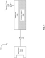
- FIG. 1 is a schematic diagram of such an example printing apparatus 100.
- the printing apparatus 100 includes a reservoir 110 to contain a printing agent 112.
- the printing agent 112 may include any printable fluid, such as printer ink, packaging ink, 3D printer ink, biological sample, chemical, or other liquid.
- the printing apparatus 100 further includes a recovery port 120 to receive connection of a recovery vessel and to communicate flow of the printing agent 112 from the reservoir 110 to the recovery vessel during a recovery operation.
- a recovery operation may involve pumping the printing agent 112 to a recovery vessel connected to the recovery port 120, and may be performed when recess printing agent 112 is to be recovered from the printing apparatus 100 for another use, such as such as upon completion of a service contract or at the end of life of a printer of which the printing apparatus 100 is a part.
- the printing apparatus 100 further includes a recovery pump 130 to pump the printing agent 112 from the reservoir 110 through the recovery port 120 to the recovery vessel during the recovery operation.
- the recovery port 120 may include an inlet/outlet which is in a closed state when not connected with a recovery vessel, and in an open state when connected with a recovery vessel to allow pumping of printing agent 112 therethrough.
- the recovery port 120 may mate by mechanical connection with the recovery vessel or associated tubing to open the inlet/outlet of the recovery port 120 and establish communication between the recovery port 120 and the recovery vessel.
- the recovery port 120 may include a closing mechanism which tends to close the inlet/outlet upon removal of the recovery vessel.
- the closing mechanism of the recovery port 120 may not close the inlet/outlet quickly enough or with enough power to prevent leakage of pressurized printing agent 112 when a recovery vessel is suddenly removed from the recovery port 120 during a recover operation.
- the printing apparatus 100 further includes a vacuum pump 140 at the reservoir 110 to reduce pressure in the reservoir 110 to below atmospheric pressure during the recovery operation to draw unrecovered printing agent 112 away from the recovery port 120 when the recovery vessel is removed from the recovery port 120.
- the recovery operation may proceed with the reservoir 110 at a negative pressure.
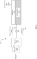
- FIG. 2 is a schematic diagram showing an example recovery vessel 202 being removed from the printing apparatus 100 of FIG. 1 during a recovery operation.
- the recovery vessel 202 is initially connected to the recovery port 120, and the recovery pump 130 is initially pumping printing agent 112 into the recovery vessel 202 in a recovery direction 204. Further, the vacuum pump 140 is maintaining negative pressure in the reservoir 110.
- FIG. 3 is a schematic diagram of another example printing apparatus 300.
- the printing apparatus 300 may be similar to the printing apparatus 100 of FIG. 1 , with like elements numbered in a "300" series rather than a "100" series, and thus, includes a reservoir 310 to contain a printing agent 312, a recovery port 320, a recovery pump 330, and may include a vacuum pump 340.
- description of the printing apparatus 100 of FIG. 1 may be referenced.
- the printing apparatus 300 may further include a pressure regulating element 350 to regulate pressure in the reservoir 310 during a recovery operation.
- the pressure regulating element 350 may include a pressure regulator or a tuned valve to regulate pressure in the reservoir 310 as the vacuum pump 340 works to reduce pressure in the reservoir 310.
- the pressure regulating element 350 may prevent the vacuum pump 340 from reducing pressure in the reservoir 310 below a predetermined threshold, such as a threshold which bounds the normal operating range of the vacuum pump 340.
- FIG. 4 is a schematic diagram of another example printing apparatus 400.
- the printing apparatus 400 may be similar to the printing apparatus 100 of FIG. 1 , with like elements numbered in a "400" series rather than a "100" series, and thus, includes a reservoir 410 to contain a printing agent 412, a recovery port 420, a recovery pump 430, and may include a vacuum pump 440.
- description of the printing apparatus 100 of FIG. 1 may be referenced.
- the printing apparatus 400 may further include a print head 450 to print the printing agent 412 onto a substrate.
- the print head 450 may be part of a print bar.
- the print head 450 may be connected to the reservoir 410 by a recirculation loop 452 which includes tubing between the reservoir 410 and the print head 450 that allows for recirculation of printing agent 412 between the print head 450 and the reservoir 410.
- the recovery pump 430 may operate as a recirculation pump to recirculate the printing agent 412 with the print head 450 during a printing operation. The recovery pump 430 may therefore communicate forward flow of printing agent 412 during a printing operation and backflow of printing agent 412 when printing agent 412 is drawn into the reservoir 410 by negative pressure.
- the printing apparatus 400 may further include a recovery line 454 to communicate flow of the printing agent 412 from the reservoir 410 to the recovery port 420 during the recovery operation.
- the recovery line 454 may branch from the recirculation loop 452.
- the recovery line 454 may include a drain valve 456 to block flow through the recovery line 454 during normal operation or a print operation and to permit flow through the recovery line 454 during a recovery operation.
- the printing apparatus 400 may further include a supply pump 458 located on a supply line 460 to pump supply printing agent from a supply vessel to the reservoir 410 during a filling operation.
- the supply pump 458 may communicate flow of unrecovered printing agent into the reservoir 410 when a recovery vessel is removed from the recovery port 420 during a recovery operation.
- printing agent 412 may be withdrawn into the reservoir 410 through the recovery pump 430 and the supply pump 458.
- FIG. 5 is a schematic diagram of another example printing apparatus 500.
- the printing apparatus 500 may be similar to the printing apparatus 100 of FIG. 1 , with like elements numbered in a "500" series rather than a "100" series, and thus, may include a reservoir 510 to contain a printing agent 512, a recovery port 520 to receive connection of a recovery vessel and to communicate flow of the printing agent 512 from the reservoir 510 to the recovery vessel during a recovery operation, and a recovery pump 530 to pump the printing agent 512 from the reservoir 510 through the recovery port 520 to the recovery vessel during the recovery operation.
- description of the printing apparatus 100 of FIG. 1 may be referenced.
- the printing apparatus 500 further includes a controller 550 to cooperate with a negative pressure element 552 at the reservoir 510 to maintain a negative pressure in the reservoir 510 during the recovery operation.
- the negative pressure is to draw unrecovered printing agent 512 away from the recovery port 520 when the recovery vessel is removed from the recovery port 520.
- the negative pressure element 552 may include a vacuum pump, a relief valve, or another element to maintain negative pressure at the reservoir 510 during a recovery operation. Where the negative pressure element includes a relief valve, the relief valve may be closed during a recovery operation, thereby allowing the recovery pump 530 to generate backpressure in the reservoir 510 as printing agent 512 is recovered into the recovery vessel.
- the controller 550 may initiate the recovery pump 530 to pump the printing agent when a recovery vessel is received at the recovery port 520. Further, the controller 550 may shut off the recovery pump 530 when a recovery vessel is removed from the recovery port 520, thereby reducing flow of printing agent 512 out of the recovery port 520.
- the printing apparatus 500 may include an electromechanical switch 554 in communication with the controller 550 which may signal to the controller 550 when the recovery vessel is received at the recovery port 520. Further, the controller 550 may initiate the negative pressure element 552 to develop negative pressure in the reservoir 510 when a recovery vessel is received at the recovery port 520. For example, where the negative pressure element 552 includes a vacuum pump, the controller 550 may control the vacuum pump to reduce pressure in the reservoir 510 when the recovery vessel is received at the recovery port 520.
- the controller may initiate the negative pressure element 552 to develop negative pressure in the reservoir 510 before the recovery pump 530 is initiated to pump the printing agent 512.
- negative pressure may be built at the reservoir 510 prior to pumping of the printing agent 512 pursuant to the recovery operation so that negative pressure draws the printing agent 512 away from the recovery port 520 even when a recovery vessel is removed from the recovery port 520 early in the recovery operation.
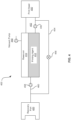
- FIG. 6 is a schematic diagram of another example printing apparatus 600.
- the printing apparatus 600 may be similar to the printing apparatus 100 of FIG. 1 , with like elements numbered in a "600" series rather than a "100" series, and thus, includes a reservoir 610-1 to contain a printing agent 612-1 and a recovery pump 630-1.
- description of the printing apparatus 100 of FIG. 1 may be referenced.
- the printing apparatus 600 may include a plurality of reservoirs to contain a plurality of printing agents.
- the printing apparatus 600 may include a first reservoir 610-1 to contain a first printing agent 612-1, a second reservoir 610-2 to contain a second printing agent 612-2, and a third reservoir 610-3 to contain a third printing agent 612-3.
- Other quantities of reservoirs and printing agents are contemplated.
- one printing agent, such as the second printing agent 612-2 may be different from another printing agent, such as the first printing agent 612-1.
- the printing apparatus 600 may include four reservoirs to contain cyan, magenta, yellow, and black inks.
- the printing apparatus 600 may include a plurality of recovery lines each including a recovery pump corresponding to each reservoir.
- the printing apparatus 600 may include a first recovery line 602-1 to communicate flow of the first printing agent 612-1 from the first reservoir 610-1 to a recovery vessel, where the first recovery line 602-1 includes a first recovery pump 630-1 to pump the first printing agent 612-1 to the recovery vessel during a recovery operation.
- the printing apparatus 600 may further include a second recovery line 602-2 to communicate flow of the second printing agent 612-2 from the second reservoir 610-2 to the recovery vessel, where the second recovery line 602-2 includes a second recovery pump 630-2 to pump the second printing agent 612-2 to the recovery vessel during the recovery operation.
- the printing apparatus 600 may further include a third recovery line 602-3 to communicate flow of the third printing agent 612-3 from the third reservoir 610-3 to the recovery vessel, where the third recovery line 602-3 includes a third recovery pump 630-3 to pump the third printing agent 612-3 to the recovery vessel during the recovery operation.
- the printing apparatus 600 may further include a negative pressure element 652 which is common to each of the reservoirs.
- the negative pressure element 652 may maintain negative pressure in the reservoirs to retract printing agent toward the reservoirs when the recovery operation is interrupted by removal of the recovery vessel.
- the negative pressure element 652 may maintain negative pressure in the first reservoir 610-1 and the second reservoir 610-2 during the recovery operation to retract the first printing agent 612-1 from the first recovery line 602-1 toward the first reservoir 610-1 when the recovery operation is interrupted and to retract the second printing agent 612-2 from the second recovery line 602-2 to the second reservoir 610-2 when the recovery operation is interrupted.
- the negative pressure element 652 may be similar to the negative pressure element 552 of the printing apparatus 500 of FIG. 5 , and thus, for further description thereof, reference may be had to the negative pressure element 552.
- the printing apparatus 600 may include additional elements from the printing apparatuses 100, 300, 400, and 500.
- the recovery lines 602-1, 602-2, 602-3, may feed into a recovery port which may be similar to the recovery port 120 of the printing apparatus 100 of FIG. 1 .
- the recovery port reference may be had to the recovery port 120 of FIG. 1 .
- the negative pressure element 652 may be controlled by a controller, which may be similar to the controller 550 of the printing apparatus 500 of FIG. 5 .
- the first reservoir 610-1 may include a first tuned valve to regulate pressure in the first reservoir 610-1
- the second reservoir 610-2 may include a second tuned valve to regulate pressure in the second reservoir 610-2
- the negative pressure element 652 may include a vacuum pump.
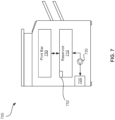
- FIG. 7 is a schematic diagram of an example printer 700.
- the printer 700 includes a reservoir 710 to contain a printing agent, a recovery port 720 to receive connection of a recovery vessel and to communicate flow of the printing agent from the reservoir 710 to the recovery vessel during a recovery operation.
- the printer 700 further includes a recovery pump 730 to pump the printing agent from the reservoir through the recovery port 720 to the recovery vessel during the recovery operation, and a print bar 750 which includes a print head for printing the printing agent during a printing operation.
- the reservoir 710 includes a negative pressure element 752 to maintain negative pressure in the reservoir 710 to draw the printing agent toward the reservoir 710 to retain printing agent in the printer 700 when a recovery operation is interrupted by removal of a recovery vessel from the recovery port 720.
- the negative pressure element 752 may be similar to the negative pressure element 552 of the printing apparatus 500 of FIG. 5 , and thus, for further description thereof, reference may be had to the negative pressure element 552.
- a printing apparatus similar to the printing apparatuses 100, 300, 400, 500, and 600 may be incorporated into a package label printer, a biological sample depositor, a 3D printer, or any other printer which prints a printable fluid
- the printing agent 112 may be any printable fluid, such as printer ink, packaging ink, 3D printing ink, biological sample, chemical, or other liquid.
- a printing apparatus may be provided which reduces, mitigates, or prevents leakage of printing agent when a recovery operation to transfer printing agent from a reservoir to a recovery vessel is unexpectedly interrupted by removal of the recovery vessel.
- the unrecovered printing agent may be retained in the printing apparatus by negative pressure drawing the printing agent back into the reservoir.
- the printing apparatus may thereby reduce waste of printing agent, and further may mitigate damage to people and equipment in the vicinity of the printing apparatus which may otherwise be caused by the accidental spillage of printing agent by the sudden removal of the recovery vessel.
Landscapes
- Ink Jet (AREA)
Description
- A printer may contain an onboard reservoir to store printing agent within the printer. The reservoir may supply a printing agent delivery system, such as an inkjet print head, with printing agent. The reservoir may be filled with printing agent by connecting a printing agent supply vessel to the printer and pumping the printing agent into the reservoir.
- At certain times, such as upon completion of a service contract or at the end of life of the printer, excess printing agent left in the reservoir may be recovered from the printer. Printing agent may be recovered from the printer by connecting a printing agent recovery vessel to the printer and pumping the printing agent into the recovery vessel.
-
EP 0 832 748 B1 describes an automatic ink interconnect between a print cartridge and a carriage.EP 1422064 B1 andUS 2001/040610 A1 disclose further relevant prior art for the present invention. - The scope of the invention is defined by the appended claims.
-
-
FIG. 1 is a schematic diagram of an example printing apparatus. -
FIG. 2 is a schematic diagram showing an example recovery vessel being removed from the printing apparatus ofFIG. 1 during a printing agent recovery operation. -
FIG. 3 is a schematic diagram of an example printing apparatus including a pressure regulating element. -
FIG. 4 is a schematic diagram of an example printing apparatus including a print head. -
FIG. 5 is a schematic diagram of an example printing apparatus including a controller to control a negative pressure element. -
FIG. 6 is a schematic diagram of an example printing apparatus including a plurality of reservoirs. -
FIG. 7 is a schematic diagram of an example printer which includes a reservoir which retains printing agent when a recovery operation is interrupted. - Unused printing agent stored in an onboard reservoir of a printer may be recovered via a recovery operation. A recovery operation may involve connecting a printing agent recovery vessel to the printer and pumping printing agent from the reservoir into the recovery vessel. If the recovery vessel is suddenly removed from the printer during the recovery operation, built-up pressure in the line from the reservoir to the recovery vessel may cause printing agent to leak out from the printer.
- Such leakage may be reduced, mitigated, or prevented by maintaining pressure in the onboard reservoir below atmospheric pressure during the recovery operation. With the onboard reservoir below atmospheric pressure, unrecovered printing agent in transit toward the recovery vessel may be drawn back toward the reservoir by negative pressure rather than allowed to leak out of the printer. The negative pressure at the reservoir is maintained by a negative pressure element such as a vacuum pump or other element capable of maintaining negative pressure in the reservoir.
- Thus, a printing apparatus includes a reservoir to contain a printing agent. The printing apparatus further includes a recovery port to receive connection of a recovery vessel and to communicate flow of the printing agent from the reservoir to the recovery vessel during a recovery operation. The printing apparatus further includes a recovery pump to pump the printing agent from the reservoir through the recovery port to the recovery vessel during the recovery operation. The printing apparatus may further include a negative pressure element, such as a vacuum pump, to maintain pressure in the reservoir below atmospheric pressure, during the recovery operation. Thus, when the recovery vessel is removed from the recovery port during the recovery operation, unrecovered printing agent is drawn away from the recovery port, and leakage of printing agent from the recovery port may thereby be reduced, mitigated, or prevented, and the printing agent may be retained in the printing apparatus.
- The negative pressure element may include a vacuum pump, a relief valve, or another element which is to maintain pressure in the reservoir such that unrecovered printing agent is retained in the printing apparatus when the recovery vessel is removed during the recovery operation. The printing apparatus includes a controller to control the negative pressure element and may include an electromechanical switch which is to signal to the controller when the recovery vessel is received at the recovery port.
-
FIG. 1 is a schematic diagram of such anexample printing apparatus 100. Theprinting apparatus 100 includes areservoir 110 to contain aprinting agent 112. Theprinting agent 112 may include any printable fluid, such as printer ink, packaging ink, 3D printer ink, biological sample, chemical, or other liquid. - The
printing apparatus 100 further includes arecovery port 120 to receive connection of a recovery vessel and to communicate flow of theprinting agent 112 from thereservoir 110 to the recovery vessel during a recovery operation. A recovery operation may involve pumping theprinting agent 112 to a recovery vessel connected to therecovery port 120, and may be performed when recessprinting agent 112 is to be recovered from theprinting apparatus 100 for another use, such as such as upon completion of a service contract or at the end of life of a printer of which theprinting apparatus 100 is a part. - The
printing apparatus 100 further includes arecovery pump 130 to pump theprinting agent 112 from thereservoir 110 through therecovery port 120 to the recovery vessel during the recovery operation. - Further, the
recovery port 120 may include an inlet/outlet which is in a closed state when not connected with a recovery vessel, and in an open state when connected with a recovery vessel to allow pumping ofprinting agent 112 therethrough. For example, therecovery port 120 may mate by mechanical connection with the recovery vessel or associated tubing to open the inlet/outlet of therecovery port 120 and establish communication between therecovery port 120 and the recovery vessel. Further, therecovery port 120 may include a closing mechanism which tends to close the inlet/outlet upon removal of the recovery vessel. - The closing mechanism of the
recovery port 120 may not close the inlet/outlet quickly enough or with enough power to prevent leakage of pressurizedprinting agent 112 when a recovery vessel is suddenly removed from therecovery port 120 during a recover operation. Thus, theprinting apparatus 100 further includes avacuum pump 140 at thereservoir 110 to reduce pressure in thereservoir 110 to below atmospheric pressure during the recovery operation to drawunrecovered printing agent 112 away from therecovery port 120 when the recovery vessel is removed from therecovery port 120. The recovery operation may proceed with thereservoir 110 at a negative pressure. -
FIG. 2 is a schematic diagram showing an example recovery vessel 202 being removed from theprinting apparatus 100 ofFIG. 1 during a recovery operation. The recovery vessel 202 is initially connected to therecovery port 120, and therecovery pump 130 is initially pumpingprinting agent 112 into the recovery vessel 202 in arecovery direction 204. Further, thevacuum pump 140 is maintaining negative pressure in thereservoir 110. - When the recovery vessel 202 is removed from the
recovery port 120, negative pressure in thereservoir 110 draws theprinting agent 112 away from therecovery port 120 in thereverse recovery direction 206, andprinting agent 112 is thereby retained in theprinting apparatus 100. -
FIG. 3 is a schematic diagram of anotherexample printing apparatus 300. Theprinting apparatus 300 may be similar to theprinting apparatus 100 ofFIG. 1 , with like elements numbered in a "300" series rather than a "100" series, and thus, includes areservoir 310 to contain aprinting agent 312, arecovery port 320, arecovery pump 330, and may include avacuum pump 340. For further description of the above elements, description of theprinting apparatus 100 ofFIG. 1 may be referenced. - The
printing apparatus 300 may further include apressure regulating element 350 to regulate pressure in thereservoir 310 during a recovery operation. Thepressure regulating element 350 may include a pressure regulator or a tuned valve to regulate pressure in thereservoir 310 as thevacuum pump 340 works to reduce pressure in thereservoir 310. Thepressure regulating element 350 may prevent thevacuum pump 340 from reducing pressure in thereservoir 310 below a predetermined threshold, such as a threshold which bounds the normal operating range of thevacuum pump 340. -
FIG. 4 is a schematic diagram of anotherexample printing apparatus 400. Theprinting apparatus 400 may be similar to theprinting apparatus 100 ofFIG. 1 , with like elements numbered in a "400" series rather than a "100" series, and thus, includes areservoir 410 to contain aprinting agent 412, arecovery port 420, arecovery pump 430, and may include avacuum pump 440. For further description of the above elements, description of theprinting apparatus 100 ofFIG. 1 may be referenced. - The
printing apparatus 400 may further include aprint head 450 to print theprinting agent 412 onto a substrate. Theprint head 450 may be part of a print bar. Theprint head 450 may be connected to thereservoir 410 by arecirculation loop 452 which includes tubing between thereservoir 410 and theprint head 450 that allows for recirculation ofprinting agent 412 between theprint head 450 and thereservoir 410. Further, therecovery pump 430 may operate as a recirculation pump to recirculate theprinting agent 412 with theprint head 450 during a printing operation. Therecovery pump 430 may therefore communicate forward flow ofprinting agent 412 during a printing operation and backflow ofprinting agent 412 whenprinting agent 412 is drawn into thereservoir 410 by negative pressure. - The
printing apparatus 400 may further include arecovery line 454 to communicate flow of theprinting agent 412 from thereservoir 410 to therecovery port 420 during the recovery operation. Therecovery line 454 may branch from therecirculation loop 452. Therecovery line 454 may include adrain valve 456 to block flow through therecovery line 454 during normal operation or a print operation and to permit flow through therecovery line 454 during a recovery operation. - The
printing apparatus 400 may further include asupply pump 458 located on asupply line 460 to pump supply printing agent from a supply vessel to thereservoir 410 during a filling operation. Thesupply pump 458 may communicate flow of unrecovered printing agent into thereservoir 410 when a recovery vessel is removed from therecovery port 420 during a recovery operation. Thus, when a recovery vessel is removed from therecovery port 420 during a recovery operation,printing agent 412 may be withdrawn into thereservoir 410 through therecovery pump 430 and thesupply pump 458. -
FIG. 5 is a schematic diagram of anotherexample printing apparatus 500. Theprinting apparatus 500 may be similar to theprinting apparatus 100 ofFIG. 1 , with like elements numbered in a "500" series rather than a "100" series, and thus, may include areservoir 510 to contain aprinting agent 512, arecovery port 520 to receive connection of a recovery vessel and to communicate flow of theprinting agent 512 from thereservoir 510 to the recovery vessel during a recovery operation, and arecovery pump 530 to pump theprinting agent 512 from thereservoir 510 through therecovery port 520 to the recovery vessel during the recovery operation. For further description of the above elements, description of theprinting apparatus 100 ofFIG. 1 may be referenced. - The
printing apparatus 500 further includes acontroller 550 to cooperate with anegative pressure element 552 at thereservoir 510 to maintain a negative pressure in thereservoir 510 during the recovery operation. The negative pressure is to drawunrecovered printing agent 512 away from therecovery port 520 when the recovery vessel is removed from therecovery port 520. - The
negative pressure element 552 may include a vacuum pump, a relief valve, or another element to maintain negative pressure at thereservoir 510 during a recovery operation. Where the negative pressure element includes a relief valve, the relief valve may be closed during a recovery operation, thereby allowing therecovery pump 530 to generate backpressure in thereservoir 510 asprinting agent 512 is recovered into the recovery vessel. - The
controller 550 may initiate therecovery pump 530 to pump the printing agent when a recovery vessel is received at therecovery port 520. Further, thecontroller 550 may shut off therecovery pump 530 when a recovery vessel is removed from therecovery port 520, thereby reducing flow ofprinting agent 512 out of therecovery port 520. - The
printing apparatus 500 may include anelectromechanical switch 554 in communication with thecontroller 550 which may signal to thecontroller 550 when the recovery vessel is received at therecovery port 520. Further, thecontroller 550 may initiate thenegative pressure element 552 to develop negative pressure in thereservoir 510 when a recovery vessel is received at therecovery port 520. For example, where thenegative pressure element 552 includes a vacuum pump, thecontroller 550 may control the vacuum pump to reduce pressure in thereservoir 510 when the recovery vessel is received at therecovery port 520. - In some examples, the controller may initiate the
negative pressure element 552 to develop negative pressure in thereservoir 510 before therecovery pump 530 is initiated to pump theprinting agent 512. Thus, negative pressure may be built at thereservoir 510 prior to pumping of theprinting agent 512 pursuant to the recovery operation so that negative pressure draws theprinting agent 512 away from therecovery port 520 even when a recovery vessel is removed from therecovery port 520 early in the recovery operation. -
FIG. 6 is a schematic diagram of anotherexample printing apparatus 600. Theprinting apparatus 600 may be similar to theprinting apparatus 100 ofFIG. 1 , with like elements numbered in a "600" series rather than a "100" series, and thus, includes a reservoir 610-1 to contain a printing agent 612-1 and a recovery pump 630-1. For further description of the above elements, description of theprinting apparatus 100 ofFIG. 1 may be referenced. - The
printing apparatus 600 may include a plurality of reservoirs to contain a plurality of printing agents. For example, theprinting apparatus 600 may include a first reservoir 610-1 to contain a first printing agent 612-1, a second reservoir 610-2 to contain a second printing agent 612-2, and a third reservoir 610-3 to contain a third printing agent 612-3. Other quantities of reservoirs and printing agents are contemplated. Further, it is contemplated that one printing agent, such as the second printing agent 612-2, may be different from another printing agent, such as the first printing agent 612-1. For example, where theprinting apparatus 600 is part of an inkjet printer which prints according to the CMYK color model, theprinting apparatus 600 may include four reservoirs to contain cyan, magenta, yellow, and black inks. - The
printing apparatus 600 may include a plurality of recovery lines each including a recovery pump corresponding to each reservoir. For example, theprinting apparatus 600 may include a first recovery line 602-1 to communicate flow of the first printing agent 612-1 from the first reservoir 610-1 to a recovery vessel, where the first recovery line 602-1 includes a first recovery pump 630-1 to pump the first printing agent 612-1 to the recovery vessel during a recovery operation. Theprinting apparatus 600 may further include a second recovery line 602-2 to communicate flow of the second printing agent 612-2 from the second reservoir 610-2 to the recovery vessel, where the second recovery line 602-2 includes a second recovery pump 630-2 to pump the second printing agent 612-2 to the recovery vessel during the recovery operation. Theprinting apparatus 600 may further include a third recovery line 602-3 to communicate flow of the third printing agent 612-3 from the third reservoir 610-3 to the recovery vessel, where the third recovery line 602-3 includes a third recovery pump 630-3 to pump the third printing agent 612-3 to the recovery vessel during the recovery operation. - The
printing apparatus 600 may further include anegative pressure element 652 which is common to each of the reservoirs. Thenegative pressure element 652 may maintain negative pressure in the reservoirs to retract printing agent toward the reservoirs when the recovery operation is interrupted by removal of the recovery vessel. For example, thenegative pressure element 652 may maintain negative pressure in the first reservoir 610-1 and the second reservoir 610-2 during the recovery operation to retract the first printing agent 612-1 from the first recovery line 602-1 toward the first reservoir 610-1 when the recovery operation is interrupted and to retract the second printing agent 612-2 from the second recovery line 602-2 to the second reservoir 610-2 when the recovery operation is interrupted. Thenegative pressure element 652 may be similar to thenegative pressure element 552 of theprinting apparatus 500 ofFIG. 5 , and thus, for further description thereof, reference may be had to thenegative pressure element 552. - The
printing apparatus 600 may include additional elements from theprinting apparatuses recovery port 120 of theprinting apparatus 100 ofFIG. 1 . For further description of the recovery port, reference may be had to therecovery port 120 ofFIG. 1 . Further, thenegative pressure element 652 may be controlled by a controller, which may be similar to thecontroller 550 of theprinting apparatus 500 ofFIG. 5 . For further description of the controller, reference may be had to thecontroller 550 ofFIG. 5 . As yet another example, the first reservoir 610-1 may include a first tuned valve to regulate pressure in the first reservoir 610-1, the second reservoir 610-2 may include a second tuned valve to regulate pressure in the second reservoir 610-2, and thenegative pressure element 652 may include a vacuum pump. -
FIG. 7 is a schematic diagram of anexample printer 700. Theprinter 700 includes areservoir 710 to contain a printing agent, arecovery port 720 to receive connection of a recovery vessel and to communicate flow of the printing agent from thereservoir 710 to the recovery vessel during a recovery operation. Theprinter 700 further includes arecovery pump 730 to pump the printing agent from the reservoir through therecovery port 720 to the recovery vessel during the recovery operation, and aprint bar 750 which includes a print head for printing the printing agent during a printing operation. - The
reservoir 710 includes anegative pressure element 752 to maintain negative pressure in thereservoir 710 to draw the printing agent toward thereservoir 710 to retain printing agent in theprinter 700 when a recovery operation is interrupted by removal of a recovery vessel from therecovery port 720. Thenegative pressure element 752 may be similar to thenegative pressure element 552 of theprinting apparatus 500 ofFIG. 5 , and thus, for further description thereof, reference may be had to thenegative pressure element 552. - In other applications, a printing apparatus similar to the
printing apparatuses printing agent 112 may be any printable fluid, such as printer ink, packaging ink, 3D printing ink, biological sample, chemical, or other liquid. - Thus, a printing apparatus may be provided which reduces, mitigates, or prevents leakage of printing agent when a recovery operation to transfer printing agent from a reservoir to a recovery vessel is unexpectedly interrupted by removal of the recovery vessel. When the recovery vessel is removed, the unrecovered printing agent may be retained in the printing apparatus by negative pressure drawing the printing agent back into the reservoir. The printing apparatus may thereby reduce waste of printing agent, and further may mitigate damage to people and equipment in the vicinity of the printing apparatus which may otherwise be caused by the accidental spillage of printing agent by the sudden removal of the recovery vessel.
Claims (14)
- A printing apparatus (100, 300, 400, 500, 600) comprising:a reservoir (110, 310, 410, 510, 610, 710) to contain a printing agent (112, 312, 412, 512);a recovery port (120, 320, 420, 520, 720) to receive connection of a recovery vessel (202) and to communicate flow of the printing agent (112, 312, 412, 512) from the reservoir (110,310, 410, 510, 610, 710) to the recovery vessel (202) during a recovery operation;a recovery pump (130, 330, 430, 530, 730) to pump the printing agent (112, 312, 412, 512) from the reservoir (110, 310, 410, 510, 610, 710) through the recovery port (120, 320, 420, 520, 720) to the recovery vessel (202) during the recovery operation;a controller (550); andcharacterized in that the printing apparatus (100, 300, 400, 500, 600) further comprises:a negative pressure element (552, 652, 752) at the reservoir (110, 310, 410, 510, 610, 710);wherein the controller (550) configured to cooperate with the negative pressure element (552, 652, 752) at the reservoir (110,310, 410, 510, 610, 710) to maintain a negative pressure in the reservoir (110, 310, 410, 510, 610, 710) during the recovery operation to draw unrecovered printing agent (112, 312, 412, 512) away from the recovery port (120, 320, 420, 520, 720) when the recovery vessel (202) is removed from the recovery port (120, 320, 420, 520, 720).
- A printing apparatus (100, 300, 400, 500, 600) as claimed in claim 1, wherein the negative pressure element is a vacuum pump and the printing apparatus (100, 300, 400, 500, 600) further comprises:the vacuum pump (140, 340, 440) at the reservoir (110, 310, 410, 510, 610, 710) to reduce pressure in the reservoir (110, 310, 410, 510, 610, 710) to below atmospheric pressure during the recovery operation, and, with the reservoir at the negative pressure, to draw unrecovered printing agent (112, 312, 412, 512) away from the recovery port (120, 320, 420, 520, 720) when the recovery vessel (202) is removed from the recovery port (120, 320, 420, 520, 720); andan electromechanical switch (554) configured to signal to the controller (550) when the recovery vessel (202) is received at the recovery port (120, 320, 420, 520, 720);wherein the controller (550) is configured to control the vacuum pump (140, 340, 440).
- The printing apparatus (100, 300, 400, 500, 600) of claim 2, wherein the recovery pump (130, 330, 430, 530, 730) is to operate as a recirculation pump to recirculate the printing agent (112, 312, 412, 512) at a print head (450) during a printing operation.
- The printing apparatus (100, 300, 400, 500, 600) of claim 3, wherein the recovery pump (130, 330, 430, 530, 730) is located along a recirculation loop (452), and wherein the printing apparatus (100, 300, 400, 500, 600) further comprises a recovery line (454, 602) to communicate flow of the printing agent (112, 312, 412, 512) from the reservoir (110, 310, 410, 510, 610, 710) to the recovery port (120, 320, 420, 520, 720) during the recovery operation, the recovery line (454, 602) branching from the recirculation loop (452).
- The printing apparatus (100, 300, 400, 500, 600) of claim 2, further comprises a supply pump (458) located on a supply line (460) to pump supply printing agent (112, 312, 412, 512) from a supply vessel to the reservoir (110, 310, 410, 510, 610, 710) during a filling operation, wherein the supply pump (458) is further to communicate flow of unrecovered printing agent (112, 312, 412, 512) into the reservoir (110, 310, 410, 510, 610, 710) when the recovery vessel (202) is removed from the recovery port (120, 320, 420, 520, 720) during the recovery operation.
- The printing apparatus (100, 300, 400, 500, 600) of claim 2, further comprising a pressure regulator to regulate pressure in the reservoir (110, 310, 410, 510, 610, 710) as the vacuum pump (140, 340, 440) reduces pressure in the reservoir (110, 310, 410, 510, 610, 710).
- The printing apparatus (100, 300, 400, 500, 600) of claim 2, further comprising a tuned valve to regulate pressure in the reservoir (110, 310, 410, 510, 610, 710) as the vacuum pump (140, 340, 440) reduces pressure in the reservoir (110, 310, 410, 510, 610, 710).
- The printing apparatus (100, 300, 400, 500, 600) of claim 1, wherein the recovery port (120, 320, 420, 520, 720) includes an electromechanical switch (554) to signal to the controller (550) when the recovery vessel (202) is received at the recovery port (120, 320, 420, 520, 720), and wherein the controller (550) is to initiate the negative pressure element (552, 652, 752) to develop negative pressure in the reservoir (110, 310, 410, 510, 610, 710) when the recovery vessel (202) is received at the recovery port (120, 320, 420, 520, 720).
- The printing apparatus (100, 300, 400, 500, 600) of claim 1, wherein the controller (550) is further to initiate the recovery pump (130, 330, 430, 530, 730) to pump the printing agent (112, 312, 412, 512) when the recovery vessel (202) is received at the recovery port (120, 320, 420, 520, 720) and to initiate the negative pressure element (552, 652, 752) to develop negative pressure in the reservoir (110, 310, 410, 510, 610, 710) before the recovery pump (130, 330, 430, 530, 730) is initiated to pump the printing agent (112, 312, 412, 512).
- The printing apparatus (100, 300, 400, 500, 600) of claim 1, wherein the controller (550) is further to shut off the recovery pump (130, 330, 430, 530, 730) when the recovery vessel (202) is removed from the recovery port (120, 320, 420, 520, 720).
- The printing apparatus (100, 300, 400, 500, 600) of claim 1, wherein the negative pressure element (552, 652, 752) includes a vacuum pump (140, 340, 440).
- The printing apparatus (100, 300, 400, 500, 600) of claim 1, wherein the negative pressure element (552, 652, 752) includes a relief valve.
- A printing apparatus (100, 300, 400, 500, 600) as claimed in claim 1,
wherein the reservoir (110, 310, 410, 510, 610, 710) is a first reservoir (610-1), the printing agent (112, 312, 412, 512) is a first printing agent (612-1) and the recovery pump (130, 330, 430, 530, 730) is a first recovery pump (630-1);
the printing apparatus (100, 300, 400, 500, 600) further comprising:a second reservoir (610-2) to contain a second printing agent (612-2) different from the first printing agent (612-1);a first recovery line (602-1) to communicate flow of the first printing agent (612-1) from the first reservoir (610-1) to a recovery vessel (202), the first recovery line (602-1) including the first recovery pump (630-1) to pump the first printing agent (612-1) to the recovery vessel (202) during the recovery operation;a second recovery line (602-2) to communicate flow of the second printing agent (612-2) from the second reservoir (610-2) to the recovery vessel (202), the second recovery line (602-2) including a second recovery pump (630-2) to pump the second printing agent (612-2) to the recovery vessel (202) during the recovery operation;the negative pressure element (552, 652, 752) to maintain negative pressure in the first reservoir (610-1) and the second reservoir (610-2) during the recovery operation to retract the first printing agent (612-1) from the first recovery line (602-1) toward the first reservoir (610-1) when the recovery operation is interrupted and to retract the second printing agent (612-2) from the second recovery line (602-2) to the second reservoir (610-2) when the recovery operation is interrupted; andan electromechanical switch (554) configured to signal to the controller (550) when the recovery vessel (202) is received at the recovery port (120, 320, 420, 520, 720);wherein the controller (550) is configured to control the negative pressure element (552, 652, 752). - The printing apparatus (100, 300, 400, 500, 600) of claim 13, wherein the first reservoir (610-1) includes a first tuned valve to regulate pressure in the first reservoir (610-1), the second reservoir (610-2) includes a second tuned valve to regulate pressure in the second reservoir (610-2), and the negative pressure element (552, 652, 752) includes a vacuum pump (140, 340, 440).
Applications Claiming Priority (1)
| Application Number | Priority Date | Filing Date | Title |
|---|---|---|---|
| PCT/US2018/063918 WO2020117220A1 (en) | 2018-12-04 | 2018-12-04 | Negative pressure recovery of printing agents |
Publications (3)
| Publication Number | Publication Date |
|---|---|
| EP3890983A1 EP3890983A1 (en) | 2021-10-13 |
| EP3890983A4 EP3890983A4 (en) | 2022-07-13 |
| EP3890983B1 true EP3890983B1 (en) | 2025-01-29 |
Family
ID=70973870
Family Applications (1)
| Application Number | Title | Priority Date | Filing Date |
|---|---|---|---|
| EP18942025.0A Active EP3890983B1 (en) | 2018-12-04 | 2018-12-04 | Negative pressure recovery of printing agents |
Country Status (3)
| Country | Link |
|---|---|
| US (1) | US11427012B2 (en) |
| EP (1) | EP3890983B1 (en) |
| WO (1) | WO2020117220A1 (en) |
Families Citing this family (1)
| Publication number | Priority date | Publication date | Assignee | Title |
|---|---|---|---|---|
| WO2021054929A1 (en) * | 2019-09-16 | 2021-03-25 | Hewlett-Packard Development Company, L.P. | Build material loading |
Family Cites Families (12)
| Publication number | Priority date | Publication date | Assignee | Title |
|---|---|---|---|---|
| CA2272155C (en) | 1992-07-31 | 2004-05-25 | Canon Kabushiki Kaisha | Liquid storing container for recording apparatus |
| US5971529A (en) | 1994-10-31 | 1999-10-26 | Hewlett-Packard Company | Automatic ink interconnect between print cartridge and carriage |
| EP1055520B1 (en) * | 1998-02-13 | 2003-10-01 | Seiko Epson Corporation | Ink jet recorder, sub-tank unit suitable therefor, and method of recovering ink droplet discharging capability |
| JP2001301192A (en) * | 2000-04-24 | 2001-10-30 | Canon Inc | Ink jet recording device |
| US6945640B2 (en) | 2002-09-11 | 2005-09-20 | Inke Pte. Ltd. | Refill station |
| JP4018513B2 (en) | 2002-11-20 | 2007-12-05 | キヤノン株式会社 | Liquid storage device |
| TWI513597B (en) | 2010-05-17 | 2015-12-21 | Memjet Technology Ltd | System for connecting a fluid supply to a printhead |
| JP5880336B2 (en) | 2012-07-31 | 2016-03-09 | ブラザー工業株式会社 | Liquid storage device |
| JP6182839B2 (en) | 2012-08-31 | 2017-08-23 | セイコーエプソン株式会社 | Ink supply device |
| JP6256804B2 (en) | 2013-12-03 | 2018-01-10 | 株式会社リコー | Liquid supply apparatus, droplet discharge apparatus, and image forming apparatus |
| US9555633B2 (en) | 2014-10-09 | 2017-01-31 | Ricoh Company, Ltd. | Replay unit for waste liquid container and image forming apparatus incorporating the relay unit |
| FR3039457B1 (en) | 2015-07-30 | 2020-10-02 | Dover Europe Sarl | LID FOR INK TANK WITH MIXING FUNCTION |
-
2018
- 2018-12-04 US US17/278,681 patent/US11427012B2/en active Active
- 2018-12-04 WO PCT/US2018/063918 patent/WO2020117220A1/en not_active Ceased
- 2018-12-04 EP EP18942025.0A patent/EP3890983B1/en active Active
Also Published As
| Publication number | Publication date |
|---|---|
| US11427012B2 (en) | 2022-08-30 |
| EP3890983A1 (en) | 2021-10-13 |
| EP3890983A4 (en) | 2022-07-13 |
| WO2020117220A1 (en) | 2020-06-11 |
| US20220040992A1 (en) | 2022-02-10 |
Similar Documents
| Publication | Publication Date | Title |
|---|---|---|
| US9272523B2 (en) | Printer configured for optimized printing | |
| KR20150038020A (en) | Printer configured for efficient air bubble removal | |
| JP6192439B2 (en) | Recording apparatus and control method | |
| CN102126350B (en) | Ink supply system and ink jet printer | |
| KR101608470B1 (en) | Inkjet printing device | |
| EP2250025B1 (en) | Printer having recycling ink and pressure-equalized upstream and downstream ink lines | |
| EP2695736A1 (en) | Inkjet recording apparatus | |
| EP3585619B1 (en) | Ink tank for regulating ink pressure | |
| JP7224838B2 (en) | RECORDING APPARATUS AND INK LEAK DETECTION METHOD IN RECORDING APPARATUS | |
| US20200101755A1 (en) | Inkjet printing apparatus with ink circulator | |
| US6158854A (en) | Connection for replacement fluid containers for ink jet printers | |
| EP3095606B1 (en) | Inkjet printer | |
| US11427012B2 (en) | Negative pressure recovery of printing agents | |
| KR101948689B1 (en) | Ink Circulation Apparatus and Method | |
| CN216001892U (en) | Ink path circulating system of ink-jet printer | |
| WO2015150148A1 (en) | Printer configured for optimized priming | |
| JP2014184565A (en) | Recording apparatus and control method | |
| WO2020032968A1 (en) | Print reservoir venting | |
| EP3795364B1 (en) | Printing apparatus and a liquid circulation method in a printing apparatus | |
| JP5488737B2 (en) | Liquid ejector | |
| US20200290363A1 (en) | Liquid ejection apparatus and liquid filling method in liquid ejection apparatus | |
| EP4069517B1 (en) | Method and system for priming dry printheads | |
| CN110281656A (en) | A kind of circulation ink system and ink road round-robin method for ink-jet printer | |
| EP4501650A1 (en) | Inkjet recording device | |
| CN211542913U (en) | Code spraying ink supply system |
Legal Events
| Date | Code | Title | Description |
|---|---|---|---|
| STAA | Information on the status of an ep patent application or granted ep patent |
Free format text: STATUS: THE INTERNATIONAL PUBLICATION HAS BEEN MADE |
|
| PUAI | Public reference made under article 153(3) epc to a published international application that has entered the european phase |
Free format text: ORIGINAL CODE: 0009012 |
|
| STAA | Information on the status of an ep patent application or granted ep patent |
Free format text: STATUS: REQUEST FOR EXAMINATION WAS MADE |
|
| 17P | Request for examination filed |
Effective date: 20210304 |
|
| AK | Designated contracting states |
Kind code of ref document: A1 Designated state(s): AL AT BE BG CH CY CZ DE DK EE ES FI FR GB GR HR HU IE IS IT LI LT LU LV MC MK MT NL NO PL PT RO RS SE SI SK SM TR |
|
| DAV | Request for validation of the european patent (deleted) | ||
| DAX | Request for extension of the european patent (deleted) | ||
| A4 | Supplementary search report drawn up and despatched |
Effective date: 20220615 |
|
| RIC1 | Information provided on ipc code assigned before grant |
Ipc: B41J 2/175 20060101ALI20220610BHEP Ipc: B67C 3/16 20060101ALI20220610BHEP Ipc: B41F 31/02 20060101ALI20220610BHEP Ipc: B41J 2/18 20060101AFI20220610BHEP |
|
| STAA | Information on the status of an ep patent application or granted ep patent |
Free format text: STATUS: EXAMINATION IS IN PROGRESS |
|
| 17Q | First examination report despatched |
Effective date: 20230925 |
|
| GRAP | Despatch of communication of intention to grant a patent |
Free format text: ORIGINAL CODE: EPIDOSNIGR1 |
|
| STAA | Information on the status of an ep patent application or granted ep patent |
Free format text: STATUS: GRANT OF PATENT IS INTENDED |
|
| INTG | Intention to grant announced |
Effective date: 20241111 |
|
| GRAS | Grant fee paid |
Free format text: ORIGINAL CODE: EPIDOSNIGR3 |
|
| GRAA | (expected) grant |
Free format text: ORIGINAL CODE: 0009210 |
|
| STAA | Information on the status of an ep patent application or granted ep patent |
Free format text: STATUS: THE PATENT HAS BEEN GRANTED |
|
| AK | Designated contracting states |
Kind code of ref document: B1 Designated state(s): AL AT BE BG CH CY CZ DE DK EE ES FI FR GB GR HR HU IE IS IT LI LT LU LV MC MK MT NL NO PL PT RO RS SE SI SK SM TR |
|
| REG | Reference to a national code |
Ref country code: GB Ref legal event code: FG4D |
|
| REG | Reference to a national code |
Ref country code: CH Ref legal event code: EP |
|
| REG | Reference to a national code |
Ref country code: DE Ref legal event code: R096 Ref document number: 602018078925 Country of ref document: DE |
|
| REG | Reference to a national code |
Ref country code: IE Ref legal event code: FG4D |
|
| REG | Reference to a national code |
Ref country code: NL Ref legal event code: MP Effective date: 20250129 |
|
| PG25 | Lapsed in a contracting state [announced via postgrant information from national office to epo] |
Ref country code: NL Free format text: LAPSE BECAUSE OF FAILURE TO SUBMIT A TRANSLATION OF THE DESCRIPTION OR TO PAY THE FEE WITHIN THE PRESCRIBED TIME-LIMIT Effective date: 20250129 |
|
| PG25 | Lapsed in a contracting state [announced via postgrant information from national office to epo] |
Ref country code: RS Free format text: LAPSE BECAUSE OF FAILURE TO SUBMIT A TRANSLATION OF THE DESCRIPTION OR TO PAY THE FEE WITHIN THE PRESCRIBED TIME-LIMIT Effective date: 20250429 |
|
| PG25 | Lapsed in a contracting state [announced via postgrant information from national office to epo] |
Ref country code: FI Free format text: LAPSE BECAUSE OF FAILURE TO SUBMIT A TRANSLATION OF THE DESCRIPTION OR TO PAY THE FEE WITHIN THE PRESCRIBED TIME-LIMIT Effective date: 20250129 |
|
| PG25 | Lapsed in a contracting state [announced via postgrant information from national office to epo] |
Ref country code: PL Free format text: LAPSE BECAUSE OF FAILURE TO SUBMIT A TRANSLATION OF THE DESCRIPTION OR TO PAY THE FEE WITHIN THE PRESCRIBED TIME-LIMIT Effective date: 20250129 |
|
| PG25 | Lapsed in a contracting state [announced via postgrant information from national office to epo] |
Ref country code: ES Free format text: LAPSE BECAUSE OF FAILURE TO SUBMIT A TRANSLATION OF THE DESCRIPTION OR TO PAY THE FEE WITHIN THE PRESCRIBED TIME-LIMIT Effective date: 20250129 |
|
| REG | Reference to a national code |
Ref country code: LT Ref legal event code: MG9D |
|
| PG25 | Lapsed in a contracting state [announced via postgrant information from national office to epo] |
Ref country code: IS Free format text: LAPSE BECAUSE OF FAILURE TO SUBMIT A TRANSLATION OF THE DESCRIPTION OR TO PAY THE FEE WITHIN THE PRESCRIBED TIME-LIMIT Effective date: 20250529 Ref country code: NO Free format text: LAPSE BECAUSE OF FAILURE TO SUBMIT A TRANSLATION OF THE DESCRIPTION OR TO PAY THE FEE WITHIN THE PRESCRIBED TIME-LIMIT Effective date: 20250429 |
|
| REG | Reference to a national code |
Ref country code: AT Ref legal event code: MK05 Ref document number: 1763081 Country of ref document: AT Kind code of ref document: T Effective date: 20250129 |
|
| PG25 | Lapsed in a contracting state [announced via postgrant information from national office to epo] |
Ref country code: HR Free format text: LAPSE BECAUSE OF FAILURE TO SUBMIT A TRANSLATION OF THE DESCRIPTION OR TO PAY THE FEE WITHIN THE PRESCRIBED TIME-LIMIT Effective date: 20250129 |
|
| PG25 | Lapsed in a contracting state [announced via postgrant information from national office to epo] |
Ref country code: PT Free format text: LAPSE BECAUSE OF FAILURE TO SUBMIT A TRANSLATION OF THE DESCRIPTION OR TO PAY THE FEE WITHIN THE PRESCRIBED TIME-LIMIT Effective date: 20250529 Ref country code: LV Free format text: LAPSE BECAUSE OF FAILURE TO SUBMIT A TRANSLATION OF THE DESCRIPTION OR TO PAY THE FEE WITHIN THE PRESCRIBED TIME-LIMIT Effective date: 20250129 |
|
| PG25 | Lapsed in a contracting state [announced via postgrant information from national office to epo] |
Ref country code: GR Free format text: LAPSE BECAUSE OF FAILURE TO SUBMIT A TRANSLATION OF THE DESCRIPTION OR TO PAY THE FEE WITHIN THE PRESCRIBED TIME-LIMIT Effective date: 20250430 Ref country code: BG Free format text: LAPSE BECAUSE OF FAILURE TO SUBMIT A TRANSLATION OF THE DESCRIPTION OR TO PAY THE FEE WITHIN THE PRESCRIBED TIME-LIMIT Effective date: 20250129 |
|
| PG25 | Lapsed in a contracting state [announced via postgrant information from national office to epo] |
Ref country code: AT Free format text: LAPSE BECAUSE OF FAILURE TO SUBMIT A TRANSLATION OF THE DESCRIPTION OR TO PAY THE FEE WITHIN THE PRESCRIBED TIME-LIMIT Effective date: 20250129 |
|
| PG25 | Lapsed in a contracting state [announced via postgrant information from national office to epo] |
Ref country code: SE Free format text: LAPSE BECAUSE OF FAILURE TO SUBMIT A TRANSLATION OF THE DESCRIPTION OR TO PAY THE FEE WITHIN THE PRESCRIBED TIME-LIMIT Effective date: 20250129 |
|
| PG25 | Lapsed in a contracting state [announced via postgrant information from national office to epo] |
Ref country code: SM Free format text: LAPSE BECAUSE OF FAILURE TO SUBMIT A TRANSLATION OF THE DESCRIPTION OR TO PAY THE FEE WITHIN THE PRESCRIBED TIME-LIMIT Effective date: 20250129 |
|
| PG25 | Lapsed in a contracting state [announced via postgrant information from national office to epo] |
Ref country code: DK Free format text: LAPSE BECAUSE OF FAILURE TO SUBMIT A TRANSLATION OF THE DESCRIPTION OR TO PAY THE FEE WITHIN THE PRESCRIBED TIME-LIMIT Effective date: 20250129 |
|
| PG25 | Lapsed in a contracting state [announced via postgrant information from national office to epo] |
Ref country code: IT Free format text: LAPSE BECAUSE OF FAILURE TO SUBMIT A TRANSLATION OF THE DESCRIPTION OR TO PAY THE FEE WITHIN THE PRESCRIBED TIME-LIMIT Effective date: 20250129 |
|
| PG25 | Lapsed in a contracting state [announced via postgrant information from national office to epo] |
Ref country code: EE Free format text: LAPSE BECAUSE OF FAILURE TO SUBMIT A TRANSLATION OF THE DESCRIPTION OR TO PAY THE FEE WITHIN THE PRESCRIBED TIME-LIMIT Effective date: 20250129 Ref country code: CZ Free format text: LAPSE BECAUSE OF FAILURE TO SUBMIT A TRANSLATION OF THE DESCRIPTION OR TO PAY THE FEE WITHIN THE PRESCRIBED TIME-LIMIT Effective date: 20250129 |
|
| PG25 | Lapsed in a contracting state [announced via postgrant information from national office to epo] |
Ref country code: RO Free format text: LAPSE BECAUSE OF FAILURE TO SUBMIT A TRANSLATION OF THE DESCRIPTION OR TO PAY THE FEE WITHIN THE PRESCRIBED TIME-LIMIT Effective date: 20250129 |
|
| PG25 | Lapsed in a contracting state [announced via postgrant information from national office to epo] |
Ref country code: SK Free format text: LAPSE BECAUSE OF FAILURE TO SUBMIT A TRANSLATION OF THE DESCRIPTION OR TO PAY THE FEE WITHIN THE PRESCRIBED TIME-LIMIT Effective date: 20250129 |
|
| REG | Reference to a national code |
Ref country code: DE Ref legal event code: R097 Ref document number: 602018078925 Country of ref document: DE |
|
| PLBE | No opposition filed within time limit |
Free format text: ORIGINAL CODE: 0009261 |
|
| STAA | Information on the status of an ep patent application or granted ep patent |
Free format text: STATUS: NO OPPOSITION FILED WITHIN TIME LIMIT |
|
| 26N | No opposition filed |
Effective date: 20251030 |
|
| PGFP | Annual fee paid to national office [announced via postgrant information from national office to epo] |
Ref country code: DE Payment date: 20251126 Year of fee payment: 8 |
|
| PGFP | Annual fee paid to national office [announced via postgrant information from national office to epo] |
Ref country code: GB Payment date: 20251120 Year of fee payment: 8 |
|
| PGFP | Annual fee paid to national office [announced via postgrant information from national office to epo] |
Ref country code: FR Payment date: 20251120 Year of fee payment: 8 |