EP3889720A1 - Work machine, work machine control method, and program - Google Patents
Work machine, work machine control method, and program Download PDFInfo
- Publication number
- EP3889720A1 EP3889720A1 EP18941100.2A EP18941100A EP3889720A1 EP 3889720 A1 EP3889720 A1 EP 3889720A1 EP 18941100 A EP18941100 A EP 18941100A EP 3889720 A1 EP3889720 A1 EP 3889720A1
- Authority
- EP
- European Patent Office
- Prior art keywords
- work machine
- failure
- trouble
- detected
- camera
- Prior art date
- Legal status (The legal status is an assumption and is not a legal conclusion. Google has not performed a legal analysis and makes no representation as to the accuracy of the status listed.)
- Granted
Links
Images

Classifications
-
- G—PHYSICS
- G05—CONTROLLING; REGULATING
- G05D—SYSTEMS FOR CONTROLLING OR REGULATING NON-ELECTRIC VARIABLES
- G05D1/00—Control of position, course, altitude or attitude of land, water, air or space vehicles, e.g. using automatic pilots
- G05D1/0055—Control of position, course, altitude or attitude of land, water, air or space vehicles, e.g. using automatic pilots with safety arrangements
- G05D1/0077—Control of position, course, altitude or attitude of land, water, air or space vehicles, e.g. using automatic pilots with safety arrangements using redundant signals or controls
-
- G—PHYSICS
- G05—CONTROLLING; REGULATING
- G05D—SYSTEMS FOR CONTROLLING OR REGULATING NON-ELECTRIC VARIABLES
- G05D1/00—Control of position, course, altitude or attitude of land, water, air or space vehicles, e.g. using automatic pilots
- G05D1/02—Control of position or course in two dimensions
- G05D1/021—Control of position or course in two dimensions specially adapted to land vehicles
- G05D1/0231—Control of position or course in two dimensions specially adapted to land vehicles using optical position detecting means
- G05D1/0246—Control of position or course in two dimensions specially adapted to land vehicles using optical position detecting means using a video camera in combination with image processing means
- G05D1/0251—Control of position or course in two dimensions specially adapted to land vehicles using optical position detecting means using a video camera in combination with image processing means extracting 3D information from a plurality of images taken from different locations, e.g. stereo vision
-
- G—PHYSICS
- G05—CONTROLLING; REGULATING
- G05D—SYSTEMS FOR CONTROLLING OR REGULATING NON-ELECTRIC VARIABLES
- G05D1/00—Control of position, course, altitude or attitude of land, water, air or space vehicles, e.g. using automatic pilots
- G05D1/0005—Control of position, course, altitude or attitude of land, water, air or space vehicles, e.g. using automatic pilots with arrangements to save energy
-
- G—PHYSICS
- G05—CONTROLLING; REGULATING
- G05D—SYSTEMS FOR CONTROLLING OR REGULATING NON-ELECTRIC VARIABLES
- G05D1/00—Control of position, course, altitude or attitude of land, water, air or space vehicles, e.g. using automatic pilots
- G05D1/02—Control of position or course in two dimensions
- G05D1/021—Control of position or course in two dimensions specially adapted to land vehicles
- G05D1/0212—Control of position or course in two dimensions specially adapted to land vehicles with means for defining a desired trajectory
- G05D1/0217—Control of position or course in two dimensions specially adapted to land vehicles with means for defining a desired trajectory in accordance with energy consumption, time reduction or distance reduction criteria
-
- G—PHYSICS
- G05—CONTROLLING; REGULATING
- G05D—SYSTEMS FOR CONTROLLING OR REGULATING NON-ELECTRIC VARIABLES
- G05D1/00—Control of position, course, altitude or attitude of land, water, air or space vehicles, e.g. using automatic pilots
- G05D1/02—Control of position or course in two dimensions
- G05D1/021—Control of position or course in two dimensions specially adapted to land vehicles
- G05D1/0231—Control of position or course in two dimensions specially adapted to land vehicles using optical position detecting means
- G05D1/0246—Control of position or course in two dimensions specially adapted to land vehicles using optical position detecting means using a video camera in combination with image processing means
Definitions
- the present invention relates to a work machine capable of autonomous traveling, a control method of the work machine, and a program.
- PTL 1 discloses an autonomous traveling system that performs autonomous traveling based on an image captured by a camera.
- PTL 2 discloses a moving work machine that includes various sensors such as an obstacle recognition sensor configured to detect a surrounding obstacle using an ultrasonic wave or the like, and performs autonomous traveling in accordance with sensor information.
- autonomous traveling is performed based on an image captured by a camera, it can be considered that in a camera failure state, autonomous traveling is maintained using various distance measuring sensors such as an ultrasonic sensor and an infrared sensor as an alternative means.
- the present invention it is possible to provide a work machine capable of autonomous traveling without using a distance measuring sensor in a camera failure state. Even if a failure occurs in one of cameras, the work machine is controlled only by the remaining cameras. Since other sensors for assisting are unnecessary, the product cost can be reduced, and an increase in power consumption can be prevented.
- Fig. 1 is a view showing the outer appearance of an autonomous work machine capable of autonomous traveling according to an embodiment of the present invention.
- the traveling direction (vehicle longitudinal direction) of the work machine in a side view a lateral direction (vehicle width direction) perpendicular to the traveling direction, and a perpendicular direction perpendicular to the traveling direction and the lateral direction are respectively defined as a front-and-rear direction, a left-and-right direction, and a vertical direction, and the arrangement of each component will be explained in accordance with these directions.
- reference numeral 10 denotes a work machine (to be referred to as "a work vehicle” hereinafter). More specifically, the work vehicle 10 functions as an autonomous traveling lawn mower. However, the lawn mower is merely an example, and the present invention is also applicable to other types of work machines.
- the work vehicle 10 has a camera unit 11 including a plurality of cameras (a first camera 11a and a second camera 11b), and can calculate and obtain information of the distance between the work vehicle 10 and an object existing in front of the work vehicle 10 by using images captured by the first and second cameras 11a and 11b having a parallax. Note that in the example shown in Fig. 1 , the camera unit 11 includes two cameras. However, the camera unit 11 may include three or more cameras.
- Fig. 2 is a view observing the work vehicle 10 in the lateral direction (vehicle width direction).
- the work vehicle 10 includes the camera unit 11, a vehicle body 12, a stay 13, front wheels 14, rear wheels 16, a blade 20, a work motor 22, a motor holding member 23, a blade height adjusting motor 100, and a translation mechanism 101.
- the work vehicle 10 also includes traveling motors 26, various sensors S, an ECU (Electronic Control Unit) 44, a charging unit 30, a battery 32, a charging terminal 34, and a notification unit 35.
- ECU Electronic Control Unit
- the vehicle body 12 of the work vehicle 10 includes a chassis 12a and a frame 12b attached to the chassis 12a.
- the front wheels 14 are two, left and right small-diameter wheels fixed to the front part of the chassis 12a via the stay 13.
- the rear wheels 16 are two, left and right large-diameter wheels attached to the rear part of the chassis 12a.
- the blade 20 is a lawn mowing rotary blade attached near the central position of the chassis 12a.
- the work motor 22 is an electric motor arranged above the blade 20.
- the blade 20 is connected to and rotated by the work motor 22.
- the motor holding member 23 holds the work motor 22.
- the rotation of the motor holding member 23 is regulated with respect to the chassis 12a.
- the vertical movement of the motor holding member 23 is permitted by a combination of a guide rail and a slider capable of vertically moving by being guided by the guide rail.
- the blade height adjusting motor 100 is a motor for adjusting the height of the blade 20 in the vertical direction from a ground surface GR.
- the translation mechanism 101 is connected to the blade height adjusting motor 100, and converts the rotation of the blade height adjusting motor 100 into a vertical translational movement.
- the translation mechanism 101 is also connected to the motor holding member 23 for holding the work motor 22.
- the rotation of the blade height adjusting motor 100 is converted into the translational movement (vertical movement) by the translation mechanism 101, and this translational movement is transmitted to the motor holding member 23.
- the translational movement (vertical movement) of the motor holding member 23 causes the work motor 22 held by the motor holding member 23 to translationally move (vertically move).
- the height of the blade 20 from the ground surface GR can be adjusted by the vertical movement of the work motor 22.
- the traveling motors 26 are two electric motors (motors) attached to the chassis 12a of the work vehicle 10.
- the two electric motors are connected to the left and right rear wheels 16.
- the left and right wheels are independently rotated forward (rotated in an advancing direction) or rotated backward (rotated in a retreating direction) by using the front wheels 14 as driven wheels and the rear wheels 16 as driving wheels. This allows the work vehicle 10 to move in various directions.
- the charging terminal 34 is a charging terminal installed in the front end position of the frame 12b in the front-and-rear direction.
- the charging terminal 34 can receive power from a charging station (not shown) when connected to a corresponding terminal of the charging station.
- the charging terminal 34 is connected to the charging unit 30 by a line, and the charging unit 30 is connected to the battery 32.
- the work motor 22, the traveling motors 26, and the blade height adjusting motor 100 are also connected to the battery 32, and receive power from the battery 32.
- the ECU 44 is an electronic control unit including a microcomputer formed on a circuit board, and controls the operation of the work vehicle 10. Details of the ECU 44 will be described later. If an abnormality occurs in the work vehicle 10, the notification unit 35 notifies the user of the occurrence of the abnormality. For example, a notification is made by a voice or display. Alternatively, the notification unit 35 outputs the abnormality occurrence to an external device connected to the work vehicle 10 by a wire or wirelessly. The user can know the occurrence of the abnormality via the external device.
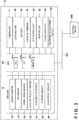
- Fig. 3 is a block diagram showing the input/output relationship of the electronic control unit (ECU) that controls the work vehicle 10.
- the ECU 44 includes a CPU 44a, an I/O 44b, and a memory 44c.
- the memory 44c is, for example, a ROM (Read Only Memory), an EEPROM (Electrically Erasable Programmable Read Only Memory), or a RAM (Random Access Memory).
- the memory 44c stores the work schedule of the work vehicle 10, information on the work area, and various programs for controlling the operation of the work vehicle 10.
- the ECU 44 can operate as each processing unit for implementing the present invention by reading out and executing a program stored in the memory 44c.
- the ECU 44 is connected to the various sensors S.
- the sensors S include an azimuth sensor 46, a GPS sensor 48, a wheel speed sensor 50, an angular velocity sensor 52, an acceleration sensor 54, a current sensor 62, and a blade height sensor 64.
- the azimuth sensor 46 and the GPS sensor 48 are sensors for obtaining information of the direction and the position of the work vehicle 10.
- the azimuth sensor 46 detects the azimuth corresponding to the terrestrial magnetism.
- the GPS sensor 48 receives radio waves from GPS satellites and detects information indicating the current position (the latitude and the longitude) of the work vehicle 10.
- the wheel speed sensor 50, the angular velocity sensor 52, and the acceleration sensor 54 are sensors for obtaining information on the moving state of the work vehicle 10.
- the wheel speed sensor 50 detects the wheel speeds of the left and right wheels 16.
- the angular velocity sensor 52 detects the angular velocity around the vertical axis (the z-axis in the perpendicular direction) in the barycentric position of the work vehicle 10.
- the acceleration sensor 54 detects accelerations in the directions of three perpendicular axes, that is, the x-, y-, and z-axes, which act on the work vehicle 10.
- the current sensor 62 detects the current consumption (power consumption) of the battery 32.
- the detection result of the current consumption (power consumption) is saved in the memory 44c of the ECU 44.
- the ECU 44 performs control for returning the work vehicle 10 to the charging station (not shown) in order to charge the work vehicle 10.
- the blade height sensor 64 detects the height of the blade 20 from the ground surface GR.
- the blade height sensor 64 outputs the detection result to the ECU 44.
- the blade height adjusting motor 100 is driven, and the blade 20 vertically moves, thereby adjusting the height from the ground surface GR.
- the outputs from the various sensors S are input to the ECU 44 via the I/O 44b. Based on the outputs from the various sensors S, the ECU 44 supplies power from the battery 32 to the traveling motor 26, the work motor 22, and the height adjusting motor 100.
- the ECU 44 controls the traveling motor 26 by outputting a control value via the I/O 44b, thereby controlling traveling of the work vehicle 10.
- the ECU 44 also controls the height adjusting motor 100 by outputting a control value via the I/O 44b, thereby controlling the height of the blade 20.
- the ECU 44 controls the work motor 22 by outputting a control value via the I/O 44b, thereby controlling the rotation of the blade 20.
- the I/O 44b can function as a communication interface, and can be connected to an external device (for example, a communication device such as a smartphone or a personal computer) 350 via a network 302 by a wire or wirelessly.
- step S401 the ECU 44 executes autonomous traveling control processing in a camera normal state. Details of this step will be described later with reference to Fig. 5 .
- step 402 the ECU 44 determines whether a failure in one of the plurality of cameras (the first camera 11a and the second camera 11b) is detected. For example, based on input signals from the camera unit 11, if the input signal is not detected from one of the cameras, occurrence of a failure may be detected. Alternatively, occurrence of a trouble may be detected in a case in which an input signal is detected, but blackout occurs in a part of the field of a camera, or the field is blurred because of a water droplet adhered to the camera.
- Occurrence of a trouble may be detected based on the brightness value of a camera image. For example, if a camera is covered with a leaf or mud, a camera image becomes dark. In this case, it is substantially impossible to obtain a camera image, and occurrence of a trouble can be detected. As described above, not only determining occurrence of a mechanical failure in a camera but also determining whether some trouble has occurred in a camera may be performed. If a failure of one of the cameras is detected, the process advances to step S403. On the other hand, if a failure is detected in neither of the cameras, that is, if both the first camera 11a and the second camera 11b are normal, the process returns to step S401 to continue the autonomous traveling control processing in the camera normal state.
- step S403 the ECU 44 temporarily stops traveling of the work vehicle 10. If traveling is continued in a state in which a failure is detected, collision against an object or deviation from the work field may occur, and therefore, traveling is stopped.
- step S404 the ECU 44 controls the notification unit 35 to notify the user of the occurrence of the failure.
- the notification unit 35 may directly notify the user of the occurrence of the failure by a voice or display via a speaker or a display mounted on the work vehicle 10.
- the notification unit 35 may wirelessly communicate with the external device 305 via the network 302 and notify the user of the occurrence of the failure via the external device 305.
- step S405 the ECU 44 executes load reduction processing of reducing the battery (battery 32) load of the work vehicle 10.
- the load reduction processing may include processing of lowering the traveling speed when the work vehicle 10 performs autonomous traveling.
- the ECU 44 may control the traveling motors 26 to lower the traveling speed to, for example, a predetermined speed.
- the load reduction processing may also include processing of lowering the rotation speed of the blade 20 provided in the work vehicle 10 by controlling the work motor 20. Processing of not lowering the speed but stopping the rotation of the blade 20 may be performed.
- the load reduction processing may also include processing of reducing the work area where the work vehicle 10 performs a work. As the load reduction processing, one or an arbitrary combination of these processes may be executed.
- step S406 the ECU 44 executes autonomous traveling control processing in camera failure state. Details of this step will be described later with reference to Fig. 6 .
- step S407 the ECU 44 determines whether the failure of the camera continues.
- the ECU 44 determines, by the same method as the failure detection method of step S402, whether the camera has a failure.
- the process advances to step S408.
- the process returns to step S401 to execute autonomous traveling control processing in the camera normal state.
- the state returns to the normal state, a case can be assumed in which, for example, a leaf that covers one camera drops due to a vibration or wind in traveling, and an appropriate camera image can be obtained again.
- step S408 the ECU 44 determines whether to continue the processing. For example, if the work vehicle 10 returns to the charging station (not shown), or the user notified of the occurrence of the failure powers off the work vehicle 10, the processing is ended. Otherwise, it is determined to continue the processing. Upon determining, in this step, to continue the processing, the process returns to step S406 to perform the autonomous traveling control processing in the camera failure state because the failure of the camera continues. On the other hand, upon determining to end the processing, the series of processes shown in Fig. 4 is ended.
- steps S403 to S405 are not essential processes, and at least some of these may be omitted.
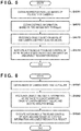
- Fig. 5 is a flowchart showing a detailed procedure of autonomous traveling control processing in the camera normal state in step S401 of Fig. 4 .
- step S4011 the ECU 44 obtains, from the camera unit 11, an image captured by the first camera 11a and an image captured by the second camera 11b. These images are images with a parallax.
- step S4012 the ECU 44 obtains the distance information between the work vehicle 10 and an object based on the parallax information of each of the images captured by the first camera 11a and the second camera 11b.
- distance information can be obtained from a plurality of images with a parallax.
- the distance information calculation method in this step is a known technique, and a detailed description thereof will be omitted.
- the ECU 44 recognizes an object based on one image captured by the first camera 11a or the second camera 11b and an analysis model for the camera normal state.
- the analysis model for the camera normal state is a model used in a normal state without a failure in a camera, and is an object recognition model used to recognize an object from an image.
- the analysis model for the camera normal state is a model incapable of obtaining distance information. As compared to another analysis model (to be described later) used in the camera failure state, the held amount of information is small, and the calculation load is small. Hence, object recognition processing can be performed in a short time.
- step S4014 the ECU 44 controls the operation of the work vehicle 10 based on the distance information obtained in step S4012 and an object recognition result obtained in step S4013.
- the work vehicle is caused to continue a work in accordance with a work plan input in advance. That is, in this embodiment, the work vehicle is caused to continue a lawn mowing work.
- the series of processes shown in Fig. 5 thus ends.
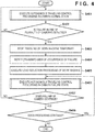
- Fig. 6 is a flowchart showing a detailed procedure of autonomous traveling control processing in the camera failure state in step S406 of Fig. 4 .
- step S4061 the ECU 44 obtains an image captured by one of the first camera 11a and the second camera 11b, which has no failure.
- step S4062 based on the image captured by the one camera without a failure and an analysis model for the camera failure state, the ECU 44 recognizes an object and obtains the distance information between the work vehicle 10 and the object.
- the analysis model for the camera failure state is an object recognition model capable of obtaining distance information, and is a model that stores the distance from the object to the work vehicle 10 and the size of the object observed at the distance in association with each other. For example, an object (for example, a marker) installed on the field where the work vehicle 10 performs a work is observed in a large size if the distance from the work vehicle 10 is short, and observed in a small size if the distance is long.
- the image is collated with the analysis model for the camera failure state, thereby obtaining the distance information up to the marker according to the size of the marker in the image.
- the analysis model for the camera failure state holds a large amount of information. Although the calculation load increases, it is possible to obtain distance information while recognizing an object as well.
- step S4063 the ECU 44 controls the operation of the work vehicle 10 based on the object recognition result and the distance information obtained in step S4062.
- the ECU 44 may perform control of returning the work vehicle 10 to the charging station.
- control of returning the work vehicle is performed in accordance with the contents of load reduction processing of the work vehicle 10.
- control of returning the work vehicle may be performed in a state in which the traveling speed of the work vehicle 10 is reduced.
- control of returning the work vehicle may be performed in a state in which the work speed of the work vehicle 10 (for example, the rotation speed of the blade 20) is lowered or in a state in which the work (rotation) is stopped.
- the work may be continued.
- the work may be continued in a state in which the traveling speed of the work vehicle 10 is reduced, or traveling may be continued in a state in which the work speed (for example, the rotation speed of the blade 20) is lowered or in a state in which the work (rotation) is stopped.
- the work may be continued while reducing the work area where the work vehicle 10 performs the work.
- the work area may be reduced such that a work area far from the charging station is reduced, and a close work area is left. The series of processes shown in Fig. 6 thus ends.
- an object recognition model incapable of measuring a distance is prepared as the analysis model used in the camera normal state
- an object recognition model capable of measuring a distance is prepared as the analysis model used in the camera failure state.
- the analysis model used in processing is switched between the camera normal state and the camera failure state.
- the analysis model used so far in the camera failure state is switched to the analysis model for the camera normal state, thereby implementing adaptive control of the work machine in accordance with the situation.
- the analysis model may be switched. The analysis model is switched based on whether the number of cameras having neither failure nor trouble in the plurality of cameras is one, thereby implementing adaptive control of the work machine in accordance with the situation.
Landscapes
- Engineering & Computer Science (AREA)
- Physics & Mathematics (AREA)
- Radar, Positioning & Navigation (AREA)
- Aviation & Aerospace Engineering (AREA)
- Remote Sensing (AREA)
- General Physics & Mathematics (AREA)
- Automation & Control Theory (AREA)
- Computer Vision & Pattern Recognition (AREA)
- Multimedia (AREA)
- Electromagnetism (AREA)
- Control Of Position, Course, Altitude, Or Attitude Of Moving Bodies (AREA)
- Harvester Elements (AREA)
- Guiding Agricultural Machines (AREA)
Abstract
Description
- The present invention relates to a work machine capable of autonomous traveling, a control method of the work machine, and a program.
- There is conventionally known an autonomous work machine (for example, a lawn mower) that measures the distance to an object in the external world and autonomously travels based on the measurement result. PTL 1 discloses an autonomous traveling system that performs autonomous traveling based on an image captured by a camera. PTL 2 discloses a moving work machine that includes various sensors such as an obstacle recognition sensor configured to detect a surrounding obstacle using an ultrasonic wave or the like, and performs autonomous traveling in accordance with sensor information.
- If autonomous traveling is performed based on an image captured by a camera, it can be considered that in a camera failure state, autonomous traveling is maintained using various distance measuring sensors such as an ultrasonic sensor and an infrared sensor as an alternative means.
-
- PTL 1:
Japanese Patent Laid-Open No. 2017-173969 - PTL 2:
Japanese Patent Laid-Open No. 9-128044 - However, if a distance measuring sensor is used in a camera failure state, power consumption increases, and the product cost also increases.
- It is an object of the present invention to provide a work machine capable of autonomous traveling without using a distance measuring sensor in a camera failure state.
- In order to solve the above-described problem and achieve the object, according to the present invention, there is provided
- a work machine that operates based on an image of a camera, comprising:
- a plurality of cameras;
- detection means for detecting a failure or a trouble in one of the plurality of cameras; and
- control means for, if the failure or the trouble is detected by the detection means, controlling the work machine based on an image captured by another camera in which the failure or the trouble is not detected.
- According to the present invention, it is possible to provide a work machine capable of autonomous traveling without using a distance measuring sensor in a camera failure state. Even if a failure occurs in one of cameras, the work machine is controlled only by the remaining cameras. Since other sensors for assisting are unnecessary, the product cost can be reduced, and an increase in power consumption can be prevented.
- Other features and advantages of the present invention will be apparent from the following description taken in conjunction with the accompanying drawings. Note that the same reference numerals denote the same or like components throughout the accompanying drawings.
- The accompanying drawings, which are incorporated in and constitute a part of the specification, illustrate embodiments of the invention and, together with the description, serve to explain principles of the invention.
-
Fig. 1 is a view showing the outer appearance of a work machine capable of autonomous traveling according to an embodiment of the present invention; -
Fig. 2 is a view observing the work machine according to the embodiment of the present invention sideways; -
Fig. 3 is a block diagram showing the input/output relationship of an electronic control unit (ECU) that controls the work machine according to the embodiment of the present invention; -
Fig. 4 is a flowchart showing a processing procedure executed by the work machine according to the embodiment of the present invention; -
Fig. 5 is a flowchart showing a detailed procedure of autonomous traveling control processing in a camera normal state according to the embodiment of the present invention; and -
Fig. 6 is a flowchart showing a detailed procedure of autonomous traveling control processing in a camera failure state according to the embodiment of the present invention. - Hereinafter, the embodiments of the present invention will be described with reference to the accompanying drawings. It should be noted that the same reference numerals denote the same constituent elements throughout the drawings.
-
Fig. 1 is a view showing the outer appearance of an autonomous work machine capable of autonomous traveling according to an embodiment of the present invention. In the following description, the traveling direction (vehicle longitudinal direction) of the work machine in a side view, a lateral direction (vehicle width direction) perpendicular to the traveling direction, and a perpendicular direction perpendicular to the traveling direction and the lateral direction are respectively defined as a front-and-rear direction, a left-and-right direction, and a vertical direction, and the arrangement of each component will be explained in accordance with these directions. - In
Fig. 1 ,reference numeral 10 denotes a work machine (to be referred to as "a work vehicle" hereinafter). More specifically, thework vehicle 10 functions as an autonomous traveling lawn mower. However, the lawn mower is merely an example, and the present invention is also applicable to other types of work machines. Thework vehicle 10 has acamera unit 11 including a plurality of cameras (afirst camera 11a and asecond camera 11b), and can calculate and obtain information of the distance between thework vehicle 10 and an object existing in front of thework vehicle 10 by using images captured by the first andsecond cameras Fig. 1 , thecamera unit 11 includes two cameras. However, thecamera unit 11 may include three or more cameras. -
Fig. 2 is a view observing thework vehicle 10 in the lateral direction (vehicle width direction). As shown inFig. 2 , thework vehicle 10 includes thecamera unit 11, avehicle body 12, astay 13,front wheels 14,rear wheels 16, ablade 20, awork motor 22, amotor holding member 23, a bladeheight adjusting motor 100, and a translation mechanism 101. Thework vehicle 10 also includestraveling motors 26, various sensors S, an ECU (Electronic Control Unit) 44, acharging unit 30, abattery 32, acharging terminal 34, and anotification unit 35. - The
vehicle body 12 of thework vehicle 10 includes achassis 12a and aframe 12b attached to thechassis 12a. Thefront wheels 14 are two, left and right small-diameter wheels fixed to the front part of thechassis 12a via thestay 13. Therear wheels 16 are two, left and right large-diameter wheels attached to the rear part of thechassis 12a. - The
blade 20 is a lawn mowing rotary blade attached near the central position of thechassis 12a. Thework motor 22 is an electric motor arranged above theblade 20. Theblade 20 is connected to and rotated by thework motor 22. Themotor holding member 23 holds thework motor 22. The rotation of themotor holding member 23 is regulated with respect to thechassis 12a. In addition, the vertical movement of themotor holding member 23 is permitted by a combination of a guide rail and a slider capable of vertically moving by being guided by the guide rail. - The blade
height adjusting motor 100 is a motor for adjusting the height of theblade 20 in the vertical direction from a ground surface GR. The translation mechanism 101 is connected to the bladeheight adjusting motor 100, and converts the rotation of the bladeheight adjusting motor 100 into a vertical translational movement. The translation mechanism 101 is also connected to themotor holding member 23 for holding thework motor 22. - The rotation of the blade
height adjusting motor 100 is converted into the translational movement (vertical movement) by the translation mechanism 101, and this translational movement is transmitted to themotor holding member 23. The translational movement (vertical movement) of themotor holding member 23 causes thework motor 22 held by themotor holding member 23 to translationally move (vertically move). The height of theblade 20 from the ground surface GR can be adjusted by the vertical movement of thework motor 22. - The
traveling motors 26 are two electric motors (motors) attached to thechassis 12a of thework vehicle 10. The two electric motors are connected to the left and rightrear wheels 16. The left and right wheels are independently rotated forward (rotated in an advancing direction) or rotated backward (rotated in a retreating direction) by using thefront wheels 14 as driven wheels and therear wheels 16 as driving wheels. This allows thework vehicle 10 to move in various directions. - The charging
terminal 34 is a charging terminal installed in the front end position of theframe 12b in the front-and-rear direction. The chargingterminal 34 can receive power from a charging station (not shown) when connected to a corresponding terminal of the charging station. The chargingterminal 34 is connected to the chargingunit 30 by a line, and the chargingunit 30 is connected to thebattery 32. Thework motor 22, the travelingmotors 26, and the bladeheight adjusting motor 100 are also connected to thebattery 32, and receive power from thebattery 32. - The
ECU 44 is an electronic control unit including a microcomputer formed on a circuit board, and controls the operation of thework vehicle 10. Details of theECU 44 will be described later. If an abnormality occurs in thework vehicle 10, thenotification unit 35 notifies the user of the occurrence of the abnormality. For example, a notification is made by a voice or display. Alternatively, thenotification unit 35 outputs the abnormality occurrence to an external device connected to thework vehicle 10 by a wire or wirelessly. The user can know the occurrence of the abnormality via the external device. -
Fig. 3 is a block diagram showing the input/output relationship of the electronic control unit (ECU) that controls thework vehicle 10. As shown inFig. 3 , theECU 44 includes aCPU 44a, an I/O 44b, and amemory 44c. Thememory 44c is, for example, a ROM (Read Only Memory), an EEPROM (Electrically Erasable Programmable Read Only Memory), or a RAM (Random Access Memory). Thememory 44c stores the work schedule of thework vehicle 10, information on the work area, and various programs for controlling the operation of thework vehicle 10. TheECU 44 can operate as each processing unit for implementing the present invention by reading out and executing a program stored in thememory 44c. - The
ECU 44 is connected to the various sensors S. The sensors S include anazimuth sensor 46, aGPS sensor 48, awheel speed sensor 50, anangular velocity sensor 52, anacceleration sensor 54, acurrent sensor 62, and ablade height sensor 64. - The
azimuth sensor 46 and theGPS sensor 48 are sensors for obtaining information of the direction and the position of thework vehicle 10. Theazimuth sensor 46 detects the azimuth corresponding to the terrestrial magnetism. TheGPS sensor 48 receives radio waves from GPS satellites and detects information indicating the current position (the latitude and the longitude) of thework vehicle 10. - The
wheel speed sensor 50, theangular velocity sensor 52, and theacceleration sensor 54 are sensors for obtaining information on the moving state of thework vehicle 10. Thewheel speed sensor 50 detects the wheel speeds of the left andright wheels 16. Theangular velocity sensor 52 detects the angular velocity around the vertical axis (the z-axis in the perpendicular direction) in the barycentric position of thework vehicle 10. Theacceleration sensor 54 detects accelerations in the directions of three perpendicular axes, that is, the x-, y-, and z-axes, which act on thework vehicle 10. - The
current sensor 62 detects the current consumption (power consumption) of thebattery 32. The detection result of the current consumption (power consumption) is saved in thememory 44c of theECU 44. When a predetermined power amount is consumed and the power amount stored in thebattery 32 becomes equal to or lower than a threshold value, theECU 44 performs control for returning thework vehicle 10 to the charging station (not shown) in order to charge thework vehicle 10. - The
blade height sensor 64 detects the height of theblade 20 from the ground surface GR. Theblade height sensor 64 outputs the detection result to theECU 44. Under the control of theECU 44, the bladeheight adjusting motor 100 is driven, and theblade 20 vertically moves, thereby adjusting the height from the ground surface GR. - The outputs from the various sensors S are input to the
ECU 44 via the I/O 44b. Based on the outputs from the various sensors S, theECU 44 supplies power from thebattery 32 to the travelingmotor 26, thework motor 22, and theheight adjusting motor 100. TheECU 44 controls the travelingmotor 26 by outputting a control value via the I/O 44b, thereby controlling traveling of thework vehicle 10. TheECU 44 also controls theheight adjusting motor 100 by outputting a control value via the I/O 44b, thereby controlling the height of theblade 20. Furthermore, theECU 44 controls thework motor 22 by outputting a control value via the I/O 44b, thereby controlling the rotation of theblade 20. The I/O 44b can function as a communication interface, and can be connected to an external device (for example, a communication device such as a smartphone or a personal computer) 350 via anetwork 302 by a wire or wirelessly. - The procedure of processing executed by the
work vehicle 10 according to this embodiment will be described next with reference to the flowchart ofFig. 4 . In this embodiment, different processes are executed in a case in which both thefirst camera 11a and thesecond camera 11b are normal without any failure and a case in which a failure has occurred in one of them. - In step S401, the
ECU 44 executes autonomous traveling control processing in a camera normal state. Details of this step will be described later with reference toFig. 5 . Instep 402, theECU 44 determines whether a failure in one of the plurality of cameras (thefirst camera 11a and thesecond camera 11b) is detected. For example, based on input signals from thecamera unit 11, if the input signal is not detected from one of the cameras, occurrence of a failure may be detected. Alternatively, occurrence of a trouble may be detected in a case in which an input signal is detected, but blackout occurs in a part of the field of a camera, or the field is blurred because of a water droplet adhered to the camera. Occurrence of a trouble may be detected based on the brightness value of a camera image. For example, if a camera is covered with a leaf or mud, a camera image becomes dark. In this case, it is substantially impossible to obtain a camera image, and occurrence of a trouble can be detected. As described above, not only determining occurrence of a mechanical failure in a camera but also determining whether some trouble has occurred in a camera may be performed. If a failure of one of the cameras is detected, the process advances to step S403. On the other hand, if a failure is detected in neither of the cameras, that is, if both thefirst camera 11a and thesecond camera 11b are normal, the process returns to step S401 to continue the autonomous traveling control processing in the camera normal state. - In step S403, the
ECU 44 temporarily stops traveling of thework vehicle 10. If traveling is continued in a state in which a failure is detected, collision against an object or deviation from the work field may occur, and therefore, traveling is stopped. - In step S404, the
ECU 44 controls thenotification unit 35 to notify the user of the occurrence of the failure. Thenotification unit 35 may directly notify the user of the occurrence of the failure by a voice or display via a speaker or a display mounted on thework vehicle 10. Alternatively, thenotification unit 35 may wirelessly communicate with the external device 305 via thenetwork 302 and notify the user of the occurrence of the failure via the external device 305. - In step S405, the
ECU 44 executes load reduction processing of reducing the battery (battery 32) load of thework vehicle 10. When a failure is detected, thework vehicle 10 should be safely returned to a station such as a charging station. To save the battery, processing of reducing the battery load is executed. For example, the load reduction processing may include processing of lowering the traveling speed when thework vehicle 10 performs autonomous traveling. TheECU 44 may control the travelingmotors 26 to lower the traveling speed to, for example, a predetermined speed. The load reduction processing may also include processing of lowering the rotation speed of theblade 20 provided in thework vehicle 10 by controlling thework motor 20. Processing of not lowering the speed but stopping the rotation of theblade 20 may be performed. The load reduction processing may also include processing of reducing the work area where thework vehicle 10 performs a work. As the load reduction processing, one or an arbitrary combination of these processes may be executed. - In step S406, the
ECU 44 executes autonomous traveling control processing in camera failure state. Details of this step will be described later with reference toFig. 6 . - In step S407, the
ECU 44 determines whether the failure of the camera continues. In this step, theECU 44 determines, by the same method as the failure detection method of step S402, whether the camera has a failure. As a result, if the failure of the camera continues, the process advances to step S408. On the other hand, if the failure of the camera does not continue, that is, all the plurality of cameras have returned to the normal state, the process returns to step S401 to execute autonomous traveling control processing in the camera normal state. As a case in which the state returns to the normal state, a case can be assumed in which, for example, a leaf that covers one camera drops due to a vibration or wind in traveling, and an appropriate camera image can be obtained again. - In step S408, the
ECU 44 determines whether to continue the processing. For example, if thework vehicle 10 returns to the charging station (not shown), or the user notified of the occurrence of the failure powers off thework vehicle 10, the processing is ended. Otherwise, it is determined to continue the processing. Upon determining, in this step, to continue the processing, the process returns to step S406 to perform the autonomous traveling control processing in the camera failure state because the failure of the camera continues. On the other hand, upon determining to end the processing, the series of processes shown inFig. 4 is ended. - Note that in the processing shown in
Fig. 4 , the description has been made using, as an example, a case in which both thefirst camera 11a and thesecond camera 11b are normal without any failure and a case in which a failure has occurred in one of them. However, a case in which failures of both cameras can occur. If a failure is detected in each camera, theECU 44 may determine that autonomous traveling is impossible and stop thework vehicle 10. The processes of steps S403 to S405 are not essential processes, and at least some of these may be omitted. -
Fig. 5 is a flowchart showing a detailed procedure of autonomous traveling control processing in the camera normal state in step S401 ofFig. 4 . - In step S4011, the
ECU 44 obtains, from thecamera unit 11, an image captured by thefirst camera 11a and an image captured by thesecond camera 11b. These images are images with a parallax. - In step S4012, the
ECU 44 obtains the distance information between thework vehicle 10 and an object based on the parallax information of each of the images captured by thefirst camera 11a and thesecond camera 11b. In this processing, distance information can be obtained from a plurality of images with a parallax. The distance information calculation method in this step is a known technique, and a detailed description thereof will be omitted. - In step S4013, the
ECU 44 recognizes an object based on one image captured by thefirst camera 11a or thesecond camera 11b and an analysis model for the camera normal state. The analysis model for the camera normal state is a model used in a normal state without a failure in a camera, and is an object recognition model used to recognize an object from an image. The analysis model for the camera normal state is a model incapable of obtaining distance information. As compared to another analysis model (to be described later) used in the camera failure state, the held amount of information is small, and the calculation load is small. Hence, object recognition processing can be performed in a short time. - In step S4014, the
ECU 44 controls the operation of thework vehicle 10 based on the distance information obtained in step S4012 and an object recognition result obtained in step S4013. Here, since no failure is detected, the work vehicle is caused to continue a work in accordance with a work plan input in advance. That is, in this embodiment, the work vehicle is caused to continue a lawn mowing work. The series of processes shown inFig. 5 thus ends. -
Fig. 6 is a flowchart showing a detailed procedure of autonomous traveling control processing in the camera failure state in step S406 ofFig. 4 . - In step S4061, the
ECU 44 obtains an image captured by one of thefirst camera 11a and thesecond camera 11b, which has no failure. - In step S4062, based on the image captured by the one camera without a failure and an analysis model for the camera failure state, the
ECU 44 recognizes an object and obtains the distance information between thework vehicle 10 and the object. The analysis model for the camera failure state is an object recognition model capable of obtaining distance information, and is a model that stores the distance from the object to thework vehicle 10 and the size of the object observed at the distance in association with each other. For example, an object (for example, a marker) installed on the field where thework vehicle 10 performs a work is observed in a large size if the distance from thework vehicle 10 is short, and observed in a small size if the distance is long. If there is an image including the marker, the image is collated with the analysis model for the camera failure state, thereby obtaining the distance information up to the marker according to the size of the marker in the image. As compared to the analysis model for the camera normal state, the analysis model for the camera failure state holds a large amount of information. Although the calculation load increases, it is possible to obtain distance information while recognizing an object as well. - In step S4063, the
ECU 44 controls the operation of thework vehicle 10 based on the object recognition result and the distance information obtained in step S4062. For example, theECU 44 may perform control of returning thework vehicle 10 to the charging station. At this time, as described concerning step S405 ofFig. 4 , control of returning the work vehicle is performed in accordance with the contents of load reduction processing of thework vehicle 10. For example, control of returning the work vehicle may be performed in a state in which the traveling speed of thework vehicle 10 is reduced. Alternatively, control of returning the work vehicle may be performed in a state in which the work speed of the work vehicle 10 (for example, the rotation speed of the blade 20) is lowered or in a state in which the work (rotation) is stopped. Instead of performing control of returning the work vehicle to the charging station, the work may be continued. At this time, the work may be continued in a state in which the traveling speed of thework vehicle 10 is reduced, or traveling may be continued in a state in which the work speed (for example, the rotation speed of the blade 20) is lowered or in a state in which the work (rotation) is stopped. Alternatively, the work may be continued while reducing the work area where thework vehicle 10 performs the work. In this case, to facilitate return to the charging station, the work area may be reduced such that a work area far from the charging station is reduced, and a close work area is left. The series of processes shown inFig. 6 thus ends. - As described above, in this embodiment, an object recognition model incapable of measuring a distance is prepared as the analysis model used in the camera normal state, and an object recognition model capable of measuring a distance is prepared as the analysis model used in the camera failure state. The analysis model used in processing is switched between the camera normal state and the camera failure state. This makes it possible to provide a work machine capable of autonomous traveling without an alternative means such as a distance measuring sensor (an ultrasonic sensor or an infrared sensor) even in the camera failure state. It is therefore possible to reduce the product cost and prevent an increase in power consumption caused by driving of a distance measuring sensor.
- Furthermore, if the camera returns from the failure state to the normal state, the analysis model used so far in the camera failure state is switched to the analysis model for the camera normal state, thereby implementing adaptive control of the work machine in accordance with the situation.
- Note that in the embodiment, an example in which the
work vehicle 10 includes two cameras has been described. However, this embodiment can also be applied even in a case in which thework vehicle 10 includes three or more cameras. For example, if a failure or a trouble occurs in two of three cameras, distance detection by parallax cannot be performed. In such a case, the analysis model may be switched. The analysis model is switched based on whether the number of cameras having neither failure nor trouble in the plurality of cameras is one, thereby implementing adaptive control of the work machine in accordance with the situation. - The present invention is not limited to the above embodiments and various changes and modifications can be made within the spirit and scope of the present invention. Therefore, to apprise the public of the scope of the present invention, the following claims are made.
-
- 1. A work machine (for example, 10) according to the above-described embodiment is a work machine (for example, 10) that operates based on an image of a camera, comprising:
- a plurality of cameras (for example, 11a, 11b);
- detection means (for example, 44) for detecting a failure or a trouble in one of the plurality of cameras; and
- control means (for example, 44) for, if the failure or the trouble is detected by the detection means, controlling the work machine based on an image captured by another camera in which the failure or the trouble is not detected.
According to this embodiment, it is possible to provide a work machine capable of autonomous traveling without using a distance measuring sensor when a failure or a trouble has occurred in the camera. In addition, even if a failure or a trouble occurs in one of the cameras, the work machine is controlled only by the remaining cameras. Since other sensors for assisting are unnecessary, the product cost can be reduced, and an increase in power consumption can be prevented.
- 2. The work machine (for example, 10) according to the above-described embodiment further comprises:
- distance obtaining means (for example, 44) for obtaining distance information between the work machine and an object based on images with a parallax which are captured by the plurality of cameras; and
- object recognition means (for example, 44) for recognizing the object based on a first analysis model and an image captured by one of the plurality of cameras,
- wherein if the failure or the trouble is not detected, the control means (for example, 44) controls an operation of the work machine based on the distance information obtained by the distance obtaining means and an object recognition result by the object recognition means.
According to this embodiment, if neither failure nor trouble occurs in the camera, the distance can be detected from images with a parallax. It is therefore possible to reduce the load of processing. - 3. In the work machine (for example, 10) according to the above-described embodiment,
the first analysis model is a model incapable of obtaining the distance information.
According to this embodiment, if neither failure nor trouble occurs in the camera, object recognition is performed using a model incapable of obtaining distance information. It is therefore possible to reduce the load of processing. - 4. The work machine (for example, 10) according to the above-described embodiment further comprises
- second object recognition means (for example, 44) for recognizing the object and obtaining the distance information between the work machine and the object based on a second analysis model and an image captured by a camera in which the failure or the trouble is not detected,
- wherein if the failure or the trouble is detected, the control means (for example, 44) controls the operation of the work machine based on the distance information obtained by the second object recognition means and an object recognition result by the second object recognition means.
According to this embodiment, when a failure or a trouble has occurred in the camera, distance information based on images with a parallax cannot be obtained. However, obtaining of the distance information can be continued based on the object recognition model.
- 5. In the work machine (for example, 10) according to the above-described embodiment,
the second analysis model is a model capable of obtaining the distance information.
According to this embodiment, obtaining of the distance information can be continued even in a camera failure state by using the model capable of obtaining distance information. - 6. In the work machine (for example, 10) according to the above-described embodiment,
if the failure or the trouble is detected by the detection means, the control means (44) executes load reduction processing of reducing a battery load of the work machine.
According to this embodiment, when a failure or a trouble has occurred in the camera, the battery load is reduced, thereby continuously operating the work machine. For example, it is possible to improve the possibility that the work machine can achieve a desired operation such as return to a station. - 7. In the work machine (for example, 10) according to the above-described embodiment,
the load reduction processing includes processing of lowering a traveling speed of the work machine.
According to this embodiment, the traveling speed of the work machine is lowered to reduce the battery load, thereby continuously operating the work machine. - 8. In the work machine (for example, 10) according to the above-described embodiment,
the load reduction processing includes processing of lowering a work speed (for example, the rotation speed) of a work unit (for example, a blade) provided in the work machine.
According to this embodiment, the work speed of the work unit provided in the work machine is lowered to reduce the battery load, thereby continuously operating the work machine. For example, the rotation speed of the blade is lowered to reduce the battery load, thereby continuously operating the work machine. - 9. In the work machine (for example, 10) according to the above-described embodiment,
the load reduction processing includes processing of reducing a work area where the work machine performs a work.
According to this embodiment, the work area where the work machine performs a work is reduced to reduce the battery load, thereby continuously operating the work machine. - 10. The work machine (for example, 10) according to the above-described embodiment further comprises
notification means (for example, 305) for making a notification of occurrence of the failure or the trouble if the failure or the trouble is detected by the detection means.
According to this embodiment, when a failure or a trouble has occurred in the camera, the user is notified of the occurrence of the failure or the trouble and can therefore early grasp the situation. - 11. In the work machine (for example, 10) according to the above-described embodiment,
if the failure or the trouble is detected by the detection means, the control means (for example, 44) performs control of returning the work machine to a station.
According to this embodiment, when a failure or a trouble has occurred in the camera, the work machine is early returned to the station, thereby preventing the operation from stopping due to battery exhaustion. - 12. In the work machine (for example, 10) according to the above-described embodiment,
- if the failure or the trouble is not detected any more by the detection means after the failure or the trouble is detected by the detection means,
- the control means (for example, 44) performs switching from the second analysis model to the first analysis model and controls the work machine using the first analysis model.
According to this embodiment, if the camera returns to a normal state, the processing is changed to processing in the normal state, thereby executing control of the work machine while reducing the processing load. In addition, since the analysis model to be used is changed in accordance with the presence/absence of a failure or a trouble, it is possible to implement control using an appropriate analysis model according to the situation.
- 13. In the work machine (for example, 10) according to the above-described embodiment,
if the failure or the trouble is detected in all the plurality of cameras by the detection means, the control means (for example, 44) stops the operation of the work machine.
According to this embodiment, if a failure or a trouble has occurred in all cameras, the operation of the work machine is stopped, thereby preventing careless movement in a state in which obtaining of distance information or object recognition is impossible. - 14. The work machine (for example, 10) according to the above-described embodiment, further comprises distance obtaining means (for example, 44) for obtaining distance information between the work machine and an object,
- wherein the distance obtaining means
- obtains the distance information based on images with a parallax which are captured by the plurality of cameras if the failure or the trouble is not detected, and
- obtains the distance information based on an analysis model and an image captured by the other camera in which the failure or the trouble is not detected if the failure or the trouble is detected, and
- the control means (for example, 44) controls the work machine based on the distance information obtained by the distance obtaining means.
According to this embodiment, if a failure or a trouble has occurred in the camera, the distance information can be continuously obtained.
- 15. A control method of the work machine (for example, 10) according to the above-described embodiment is
a control method of a work machine (for example, 10) that operates based on an image of a camera, comprising:- a detection step of detecting a failure or a trouble in one of a plurality of cameras (for example, 11a, 11b) provided in the work machine; and
- a control step of, if the failure or the trouble is detected in the detection step, controlling the work machine based on an image captured by another camera in which the failure or the trouble is not detected.
According to this embodiment, even if a failure or a trouble occurs in one of the cameras, the work machine is controlled only by the remaining cameras. Since other sensors for assisting are unnecessary, the product cost can be reduced, and an increase in power consumption can be prevented.
- 16. A program according to the above-described embodiment is
a program configured to cause a computer to function as a work machine defined in any one of claims 1 to 14.
According to this embodiment, even if a failure or a trouble occurs in one of the cameras, control of controlling the work machine only by the remaining cameras can be implemented by the computer program.
Claims (16)
- A work machine that operates based on an image of a camera, characterized by comprising:a plurality of cameras;detection means for detecting a failure or a trouble in one of the plurality of cameras; andcontrol means for, if the failure or the trouble is detected by the detection means, controlling the work machine based on an image captured by another camera in which the failure or the trouble is not detected.
- The work machine according to claim 1, characterized by further comprising:distance obtaining means for obtaining distance information between the work machine and an object based on images with a parallax which are captured by the plurality of cameras; andobject recognition means for recognizing the object based on a first analysis model and an image captured by one of the plurality of cameras,wherein if the failure or the trouble is not detected, the control means controls an operation of the work machine based on the distance information obtained by the distance obtaining means and an object recognition result by the object recognition means.
- The work machine according to claim 2, characterized in that the first analysis model is a model incapable of obtaining the distance information.
- The work machine according to claim 2 or 3, characterized by further comprising second object recognition means for recognizing the object and obtaining the distance information between the work machine and the object based on a second analysis model and an image captured by a camera in which the failure or the trouble is not detected,
wherein if the failure or the trouble is detected, the control means controls the operation of the work machine based on the distance information obtained by the second object recognition means and an object recognition result by the second object recognition means. - The work machine according to claim 4, characterized in that the second analysis model is a model capable of obtaining the distance information.
- The work machine according to any one of claims 1 to 5, characterized in that if the failure or the trouble is detected by the detection means, the control means executes load reduction processing of reducing a battery load of the work machine.
- The work machine according to claim 6, characterized in that the load reduction processing includes processing of lowering a traveling speed of the work machine.
- The work machine according to claim 6 or 7, characterized in that the load reduction processing includes processing of lowering a work speed of a work unit provided in the work machine.
- The work machine according to any one of claims 6 to 8, characterized in that the load reduction processing includes processing of reducing a work area where the work machine performs a work.
- The work machine according to any one of claims 1 to 9, characterized by further comprising notification means for making a notification of occurrence of the failure or the trouble if the failure or the trouble is detected by the detection means.
- The work machine according to any one of claims 1 to 10, characterized in that if the failure or the trouble is detected by the detection means, the control means performs control of returning the work machine to a station.
- The work machine according to claim 4 or 5, characterized in that if the failure or the trouble is not detected any more by the detection means after the failure or the trouble is detected by the detection means,
the control means performs switching from the second analysis model to the first analysis model and controls the work machine using the first analysis model. - The work machine according to any one of claims 1 to 12, characterized in that if the failure or the trouble is detected in all the plurality of cameras by the detection means, the control means stops the operation of the work machine.
- The work machine according to claim 1, characterized by further comprising distance obtaining means for obtaining distance information between the work machine and an object,wherein the distance obtaining meansobtains the distance information based on images with a parallax which are captured by the plurality of cameras if the failure or the trouble is not detected, andobtains the distance information based on an analysis model and an image captured by the other camera in which the failure or the trouble is not detected if the failure or the trouble is detected, andthe control means controls the work machine based on the distance information obtained by the distance obtaining means.
- A control method of a work machine that operates based on an image of a camera, characterized by comprising:a detection step of detecting a failure or a trouble in one of a plurality of cameras provided in the work machine; anda control step of, if the failure or the trouble is detected in the detection step, controlling the work machine based on an image captured by another camera in which the failure or the trouble is not detected.
- A program configured to cause a computer to function as a work machine defined in any one of claims 1 to 14.
Applications Claiming Priority (1)
| Application Number | Priority Date | Filing Date | Title |
|---|---|---|---|
| PCT/JP2018/043890 WO2020110248A1 (en) | 2018-11-29 | 2018-11-29 | Work machine, work machine control method, and program |
Publications (3)
| Publication Number | Publication Date |
|---|---|
| EP3889720A1 true EP3889720A1 (en) | 2021-10-06 |
| EP3889720A4 EP3889720A4 (en) | 2021-11-24 |
| EP3889720B1 EP3889720B1 (en) | 2023-04-05 |
Family
ID=70853164
Family Applications (1)
| Application Number | Title | Priority Date | Filing Date |
|---|---|---|---|
| EP18941100.2A Active EP3889720B1 (en) | 2018-11-29 | 2018-11-29 | Work machine, work machine control method, and program |
Country Status (4)
| Country | Link |
|---|---|
| US (1) | US20210278839A1 (en) |
| EP (1) | EP3889720B1 (en) |
| JP (1) | JP7168682B2 (en) |
| WO (1) | WO2020110248A1 (en) |
Families Citing this family (1)
| Publication number | Priority date | Publication date | Assignee | Title |
|---|---|---|---|---|
| JP7599237B1 (en) | 2023-08-18 | 2024-12-13 | 株式会社エイトノット | Information Processing System |
Family Cites Families (20)
| Publication number | Priority date | Publication date | Assignee | Title |
|---|---|---|---|---|
| JPH01195515A (en) * | 1988-01-29 | 1989-08-07 | Matsushita Electric Ind Co Ltd | Self-driving sweeper |
| JPH09128044A (en) | 1995-11-02 | 1997-05-16 | Hitachi Ltd | Semi-automatic control system for traveling work machine |
| JP3866328B2 (en) * | 1996-06-06 | 2007-01-10 | 富士重工業株式会社 | Vehicle peripheral three-dimensional object recognition device |
| JPH1088625A (en) * | 1996-09-13 | 1998-04-07 | Komatsu Ltd | Automatic excavator, automatic excavation method and automatic loading method |
| JPH11282533A (en) * | 1998-03-26 | 1999-10-15 | Sharp Corp | Mobile robot system |
| JP2002351546A (en) * | 2001-05-22 | 2002-12-06 | Murata Mach Ltd | Automatic guided vehicle system |
| US7133746B2 (en) * | 2003-07-11 | 2006-11-07 | F Robotics Acquistions, Ltd. | Autonomous machine for docking with a docking station and method for docking |
| JP5016409B2 (en) * | 2007-07-26 | 2012-09-05 | パナソニック株式会社 | Autonomous mobile device |
| US9586563B2 (en) | 2012-09-28 | 2017-03-07 | Hitachi, Ltd. | Autonomous moving apparatus and autonomous movement system |
| WO2014064990A1 (en) * | 2012-10-25 | 2014-05-01 | シャープ株式会社 | Plane detection device, autonomous locomotion device provided with plane detection device, method for detecting road level difference, device for detecting road level difference, and vehicle provided with device for detecting road level difference |
| JP6066487B2 (en) * | 2013-07-26 | 2017-01-25 | ヤンマー株式会社 | Electric work vehicle |
| JP2014238409A (en) * | 2014-07-23 | 2014-12-18 | 日立オートモティブシステムズ株式会社 | Distance calculation device and distance calculation method |
| JP6431746B2 (en) * | 2014-11-06 | 2018-11-28 | 日立アプライアンス株式会社 | Automatic return system, base station and autonomous traveling type vacuum cleaner |
| US20160128275A1 (en) * | 2014-11-12 | 2016-05-12 | Deere & Company | Robotic mower contact detection system |
| WO2016047808A1 (en) * | 2015-09-30 | 2016-03-31 | 株式会社小松製作所 | Calibration system for imaging device, working machine, and calibration method for imaging device |
| WO2017094122A1 (en) * | 2015-12-01 | 2017-06-08 | オリンパス株式会社 | Imaging device, endoscope device, and imaging method |
| JP6440647B2 (en) | 2016-03-22 | 2018-12-19 | ヤンマー株式会社 | Autonomous driving system |
| US10338594B2 (en) * | 2017-03-13 | 2019-07-02 | Nio Usa, Inc. | Navigation of autonomous vehicles to enhance safety under one or more fault conditions |
| JP6944308B2 (en) * | 2017-08-18 | 2021-10-06 | ソニーセミコンダクタソリューションズ株式会社 | Control devices, control systems, and control methods |
| JP7232005B2 (en) * | 2018-09-20 | 2023-03-02 | 株式会社Subaru | VEHICLE DRIVING ENVIRONMENT DETECTION DEVICE AND DRIVING CONTROL SYSTEM |
-
2018
- 2018-11-29 WO PCT/JP2018/043890 patent/WO2020110248A1/en not_active Ceased
- 2018-11-29 JP JP2020557474A patent/JP7168682B2/en active Active
- 2018-11-29 EP EP18941100.2A patent/EP3889720B1/en active Active
-
2021
- 2021-05-21 US US17/326,921 patent/US20210278839A1/en not_active Abandoned
Also Published As
| Publication number | Publication date |
|---|---|
| EP3889720B1 (en) | 2023-04-05 |
| EP3889720A4 (en) | 2021-11-24 |
| JP7168682B2 (en) | 2022-11-09 |
| WO2020110248A1 (en) | 2020-06-04 |
| JPWO2020110248A1 (en) | 2021-12-23 |
| US20210278839A1 (en) | 2021-09-09 |
Similar Documents
| Publication | Publication Date | Title |
|---|---|---|
| US12093059B2 (en) | Control system, control apparatus, autonomous work machine, operation method of control apparatus, control method of autonomous work machine, and storage medium | |
| EP3884749B1 (en) | Autonomous work machine, autonomous work machine control method, and program | |
| US11230291B2 (en) | Vehicle control system | |
| US20210271247A1 (en) | Autonomous work machine, method of controlling the same, and storage medium | |
| US10305527B2 (en) | Communicatively coupling mobile devices to wireless local area networks of vehicles | |
| US12097778B2 (en) | Electric motor vehicle | |
| EP3874924B1 (en) | Autonomous work machine, autonomous work machine control method, and program | |
| US12041872B2 (en) | Autonomous work machine, autonomous work system, method of controlling autonomous work machine, and storage medium | |
| US20220196424A1 (en) | Vehicle control method and vehicle control device | |
| US11653804B2 (en) | Work system, autonomous work machine, method of controlling autonomous work machine, and non-transitory computer-readable storage medium | |
| US20210365692A1 (en) | Vehicle periphery monitoring system | |
| US20240069206A1 (en) | Apparatus for estimating vehicle pose using lidar sensor and method thereof | |
| US20230249700A1 (en) | Vehicle management system and vehicle management method | |
| CN106774318A (en) | Multiple agent interactive environment is perceived and path planning kinematic system | |
| US12054058B2 (en) | Vehicle charging system and vehicle | |
| CN110096056A (en) | A kind of intelligent vehicle detection system and its control method based on unmanned aerial vehicle platform | |
| US11892850B2 (en) | Autonomous work machine, method of controlling the same, and storage medium | |
| EP3889720B1 (en) | Work machine, work machine control method, and program | |
| US20220137639A1 (en) | Autonomous work system | |
| US20240428599A1 (en) | Adaptive camera misalignment correction and road geometry compensation for lane detection | |
| EP3977722B1 (en) | Electric vehicle with autonomous drive | |
| CN110481518A (en) | Control method, device and the electronic device of auxiliary support wheel | |
| CN114485725A (en) | Data anomaly detection method, automatic driving platform and computer readable storage medium | |
| CN111504307B (en) | Vehicle-mounted intelligent combined navigation equipment | |
| CN220199173U (en) | AGV dolly based on inertia direction calibration |
Legal Events
| Date | Code | Title | Description |
|---|---|---|---|
| STAA | Information on the status of an ep patent application or granted ep patent |
Free format text: STATUS: THE INTERNATIONAL PUBLICATION HAS BEEN MADE |
|
| PUAI | Public reference made under article 153(3) epc to a published international application that has entered the european phase |
Free format text: ORIGINAL CODE: 0009012 |
|
| STAA | Information on the status of an ep patent application or granted ep patent |
Free format text: STATUS: REQUEST FOR EXAMINATION WAS MADE |
|
| 17P | Request for examination filed |
Effective date: 20210610 |
|
| AK | Designated contracting states |
Kind code of ref document: A1 Designated state(s): AL AT BE BG CH CY CZ DE DK EE ES FI FR GB GR HR HU IE IS IT LI LT LU LV MC MK MT NL NO PL PT RO RS SE SI SK SM TR |
|
| A4 | Supplementary search report drawn up and despatched |
Effective date: 20211022 |
|
| RIC1 | Information provided on ipc code assigned before grant |
Ipc: G05D 1/02 20200101AFI20211018BHEP |
|
| DAV | Request for validation of the european patent (deleted) | ||
| DAX | Request for extension of the european patent (deleted) | ||
| STAA | Information on the status of an ep patent application or granted ep patent |
Free format text: STATUS: EXAMINATION IS IN PROGRESS |
|
| 17Q | First examination report despatched |
Effective date: 20220607 |
|
| GRAP | Despatch of communication of intention to grant a patent |
Free format text: ORIGINAL CODE: EPIDOSNIGR1 |
|
| STAA | Information on the status of an ep patent application or granted ep patent |
Free format text: STATUS: GRANT OF PATENT IS INTENDED |
|
| INTG | Intention to grant announced |
Effective date: 20221117 |
|
| GRAS | Grant fee paid |
Free format text: ORIGINAL CODE: EPIDOSNIGR3 |
|
| GRAA | (expected) grant |
Free format text: ORIGINAL CODE: 0009210 |
|
| STAA | Information on the status of an ep patent application or granted ep patent |
Free format text: STATUS: THE PATENT HAS BEEN GRANTED |
|
| AK | Designated contracting states |
Kind code of ref document: B1 Designated state(s): AL AT BE BG CH CY CZ DE DK EE ES FI FR GB GR HR HU IE IS IT LI LT LU LV MC MK MT NL NO PL PT RO RS SE SI SK SM TR |
|
| REG | Reference to a national code |
Ref country code: GB Ref legal event code: FG4D |
|
| REG | Reference to a national code |
Ref country code: DE Ref legal event code: R096 Ref document number: 602018048229 Country of ref document: DE |
|
| REG | Reference to a national code |
Ref country code: CH Ref legal event code: EP |
|
| REG | Reference to a national code |
Ref country code: AT Ref legal event code: REF Ref document number: 1558704 Country of ref document: AT Kind code of ref document: T Effective date: 20230415 |
|
| REG | Reference to a national code |
Ref country code: IE Ref legal event code: FG4D |
|
| REG | Reference to a national code |
Ref country code: DE Ref legal event code: R084 Ref document number: 602018048229 Country of ref document: DE |
|
| REG | Reference to a national code |
Ref country code: LT Ref legal event code: MG9D |
|
| REG | Reference to a national code |
Ref country code: NL Ref legal event code: MP Effective date: 20230405 |
|
| REG | Reference to a national code |
Ref country code: AT Ref legal event code: MK05 Ref document number: 1558704 Country of ref document: AT Kind code of ref document: T Effective date: 20230405 |
|
| PG25 | Lapsed in a contracting state [announced via postgrant information from national office to epo] |
Ref country code: NL Free format text: LAPSE BECAUSE OF FAILURE TO SUBMIT A TRANSLATION OF THE DESCRIPTION OR TO PAY THE FEE WITHIN THE PRESCRIBED TIME-LIMIT Effective date: 20230405 |
|
| PG25 | Lapsed in a contracting state [announced via postgrant information from national office to epo] |
Ref country code: SE Free format text: LAPSE BECAUSE OF FAILURE TO SUBMIT A TRANSLATION OF THE DESCRIPTION OR TO PAY THE FEE WITHIN THE PRESCRIBED TIME-LIMIT Effective date: 20230405 Ref country code: PT Free format text: LAPSE BECAUSE OF FAILURE TO SUBMIT A TRANSLATION OF THE DESCRIPTION OR TO PAY THE FEE WITHIN THE PRESCRIBED TIME-LIMIT Effective date: 20230807 Ref country code: NO Free format text: LAPSE BECAUSE OF FAILURE TO SUBMIT A TRANSLATION OF THE DESCRIPTION OR TO PAY THE FEE WITHIN THE PRESCRIBED TIME-LIMIT Effective date: 20230705 Ref country code: ES Free format text: LAPSE BECAUSE OF FAILURE TO SUBMIT A TRANSLATION OF THE DESCRIPTION OR TO PAY THE FEE WITHIN THE PRESCRIBED TIME-LIMIT Effective date: 20230405 Ref country code: AT Free format text: LAPSE BECAUSE OF FAILURE TO SUBMIT A TRANSLATION OF THE DESCRIPTION OR TO PAY THE FEE WITHIN THE PRESCRIBED TIME-LIMIT Effective date: 20230405 |
|
| REG | Reference to a national code |
Ref country code: DE Ref legal event code: R079 Ref document number: 602018048229 Country of ref document: DE Free format text: PREVIOUS MAIN CLASS: G05D0001020000 Ipc: G05D0001430000 |
|
| PG25 | Lapsed in a contracting state [announced via postgrant information from national office to epo] |
Ref country code: RS Free format text: LAPSE BECAUSE OF FAILURE TO SUBMIT A TRANSLATION OF THE DESCRIPTION OR TO PAY THE FEE WITHIN THE PRESCRIBED TIME-LIMIT Effective date: 20230405 Ref country code: PL Free format text: LAPSE BECAUSE OF FAILURE TO SUBMIT A TRANSLATION OF THE DESCRIPTION OR TO PAY THE FEE WITHIN THE PRESCRIBED TIME-LIMIT Effective date: 20230405 Ref country code: LV Free format text: LAPSE BECAUSE OF FAILURE TO SUBMIT A TRANSLATION OF THE DESCRIPTION OR TO PAY THE FEE WITHIN THE PRESCRIBED TIME-LIMIT Effective date: 20230405 Ref country code: LT Free format text: LAPSE BECAUSE OF FAILURE TO SUBMIT A TRANSLATION OF THE DESCRIPTION OR TO PAY THE FEE WITHIN THE PRESCRIBED TIME-LIMIT Effective date: 20230405 Ref country code: IS Free format text: LAPSE BECAUSE OF FAILURE TO SUBMIT A TRANSLATION OF THE DESCRIPTION OR TO PAY THE FEE WITHIN THE PRESCRIBED TIME-LIMIT Effective date: 20230805 Ref country code: HR Free format text: LAPSE BECAUSE OF FAILURE TO SUBMIT A TRANSLATION OF THE DESCRIPTION OR TO PAY THE FEE WITHIN THE PRESCRIBED TIME-LIMIT Effective date: 20230405 Ref country code: GR Free format text: LAPSE BECAUSE OF FAILURE TO SUBMIT A TRANSLATION OF THE DESCRIPTION OR TO PAY THE FEE WITHIN THE PRESCRIBED TIME-LIMIT Effective date: 20230706 Ref country code: AL Free format text: LAPSE BECAUSE OF FAILURE TO SUBMIT A TRANSLATION OF THE DESCRIPTION OR TO PAY THE FEE WITHIN THE PRESCRIBED TIME-LIMIT Effective date: 20230405 |
|
| PG25 | Lapsed in a contracting state [announced via postgrant information from national office to epo] |
Ref country code: FI Free format text: LAPSE BECAUSE OF FAILURE TO SUBMIT A TRANSLATION OF THE DESCRIPTION OR TO PAY THE FEE WITHIN THE PRESCRIBED TIME-LIMIT Effective date: 20230405 |
|
| REG | Reference to a national code |
Ref country code: DE Ref legal event code: R097 Ref document number: 602018048229 Country of ref document: DE |
|
| PG25 | Lapsed in a contracting state [announced via postgrant information from national office to epo] |
Ref country code: SK Free format text: LAPSE BECAUSE OF FAILURE TO SUBMIT A TRANSLATION OF THE DESCRIPTION OR TO PAY THE FEE WITHIN THE PRESCRIBED TIME-LIMIT Effective date: 20230405 |
|
| PG25 | Lapsed in a contracting state [announced via postgrant information from national office to epo] |
Ref country code: SM Free format text: LAPSE BECAUSE OF FAILURE TO SUBMIT A TRANSLATION OF THE DESCRIPTION OR TO PAY THE FEE WITHIN THE PRESCRIBED TIME-LIMIT Effective date: 20230405 Ref country code: SK Free format text: LAPSE BECAUSE OF FAILURE TO SUBMIT A TRANSLATION OF THE DESCRIPTION OR TO PAY THE FEE WITHIN THE PRESCRIBED TIME-LIMIT Effective date: 20230405 Ref country code: RO Free format text: LAPSE BECAUSE OF FAILURE TO SUBMIT A TRANSLATION OF THE DESCRIPTION OR TO PAY THE FEE WITHIN THE PRESCRIBED TIME-LIMIT Effective date: 20230405 Ref country code: EE Free format text: LAPSE BECAUSE OF FAILURE TO SUBMIT A TRANSLATION OF THE DESCRIPTION OR TO PAY THE FEE WITHIN THE PRESCRIBED TIME-LIMIT Effective date: 20230405 Ref country code: DK Free format text: LAPSE BECAUSE OF FAILURE TO SUBMIT A TRANSLATION OF THE DESCRIPTION OR TO PAY THE FEE WITHIN THE PRESCRIBED TIME-LIMIT Effective date: 20230405 Ref country code: CZ Free format text: LAPSE BECAUSE OF FAILURE TO SUBMIT A TRANSLATION OF THE DESCRIPTION OR TO PAY THE FEE WITHIN THE PRESCRIBED TIME-LIMIT Effective date: 20230405 |
|
| PLBE | No opposition filed within time limit |
Free format text: ORIGINAL CODE: 0009261 |
|
| STAA | Information on the status of an ep patent application or granted ep patent |
Free format text: STATUS: NO OPPOSITION FILED WITHIN TIME LIMIT |
|
| 26N | No opposition filed |
Effective date: 20240108 |
|
| PG25 | Lapsed in a contracting state [announced via postgrant information from national office to epo] |
Ref country code: SI Free format text: LAPSE BECAUSE OF FAILURE TO SUBMIT A TRANSLATION OF THE DESCRIPTION OR TO PAY THE FEE WITHIN THE PRESCRIBED TIME-LIMIT Effective date: 20230405 |
|
| PG25 | Lapsed in a contracting state [announced via postgrant information from national office to epo] |
Ref country code: SI Free format text: LAPSE BECAUSE OF FAILURE TO SUBMIT A TRANSLATION OF THE DESCRIPTION OR TO PAY THE FEE WITHIN THE PRESCRIBED TIME-LIMIT Effective date: 20230405 Ref country code: IT Free format text: LAPSE BECAUSE OF FAILURE TO SUBMIT A TRANSLATION OF THE DESCRIPTION OR TO PAY THE FEE WITHIN THE PRESCRIBED TIME-LIMIT Effective date: 20230405 |
|
| REG | Reference to a national code |
Ref country code: CH Ref legal event code: PL |
|
| PG25 | Lapsed in a contracting state [announced via postgrant information from national office to epo] |
Ref country code: MC Free format text: LAPSE BECAUSE OF FAILURE TO SUBMIT A TRANSLATION OF THE DESCRIPTION OR TO PAY THE FEE WITHIN THE PRESCRIBED TIME-LIMIT Effective date: 20230405 |
|
| PG25 | Lapsed in a contracting state [announced via postgrant information from national office to epo] |
Ref country code: LU Free format text: LAPSE BECAUSE OF NON-PAYMENT OF DUE FEES Effective date: 20231129 |
|
| PG25 | Lapsed in a contracting state [announced via postgrant information from national office to epo] |
Ref country code: CH Free format text: LAPSE BECAUSE OF NON-PAYMENT OF DUE FEES Effective date: 20231130 |
|
| GBPC | Gb: european patent ceased through non-payment of renewal fee |
Effective date: 20231129 |
|
| PG25 | Lapsed in a contracting state [announced via postgrant information from national office to epo] |
Ref country code: MC Free format text: LAPSE BECAUSE OF FAILURE TO SUBMIT A TRANSLATION OF THE DESCRIPTION OR TO PAY THE FEE WITHIN THE PRESCRIBED TIME-LIMIT Effective date: 20230405 Ref country code: LU Free format text: LAPSE BECAUSE OF NON-PAYMENT OF DUE FEES Effective date: 20231129 Ref country code: CH Free format text: LAPSE BECAUSE OF NON-PAYMENT OF DUE FEES Effective date: 20231130 |
|
| REG | Reference to a national code |
Ref country code: BE Ref legal event code: MM Effective date: 20231130 |
|
| REG | Reference to a national code |
Ref country code: IE Ref legal event code: MM4A |
|
| PG25 | Lapsed in a contracting state [announced via postgrant information from national office to epo] |
Ref country code: IE Free format text: LAPSE BECAUSE OF NON-PAYMENT OF DUE FEES Effective date: 20231129 |
|
| PG25 | Lapsed in a contracting state [announced via postgrant information from national office to epo] |
Ref country code: GB Free format text: LAPSE BECAUSE OF NON-PAYMENT OF DUE FEES Effective date: 20231129 |
|
| PG25 | Lapsed in a contracting state [announced via postgrant information from national office to epo] |
Ref country code: BE Free format text: LAPSE BECAUSE OF NON-PAYMENT OF DUE FEES Effective date: 20231130 |
|
| PG25 | Lapsed in a contracting state [announced via postgrant information from national office to epo] |
Ref country code: FR Free format text: LAPSE BECAUSE OF NON-PAYMENT OF DUE FEES Effective date: 20231130 |
|
| PG25 | Lapsed in a contracting state [announced via postgrant information from national office to epo] |
Ref country code: IE Free format text: LAPSE BECAUSE OF NON-PAYMENT OF DUE FEES Effective date: 20231129 Ref country code: GB Free format text: LAPSE BECAUSE OF NON-PAYMENT OF DUE FEES Effective date: 20231129 Ref country code: FR Free format text: LAPSE BECAUSE OF NON-PAYMENT OF DUE FEES Effective date: 20231130 Ref country code: BE Free format text: LAPSE BECAUSE OF NON-PAYMENT OF DUE FEES Effective date: 20231130 |
|
| PG25 | Lapsed in a contracting state [announced via postgrant information from national office to epo] |
Ref country code: BG Free format text: LAPSE BECAUSE OF FAILURE TO SUBMIT A TRANSLATION OF THE DESCRIPTION OR TO PAY THE FEE WITHIN THE PRESCRIBED TIME-LIMIT Effective date: 20230405 |
|
| PG25 | Lapsed in a contracting state [announced via postgrant information from national office to epo] |
Ref country code: BG Free format text: LAPSE BECAUSE OF FAILURE TO SUBMIT A TRANSLATION OF THE DESCRIPTION OR TO PAY THE FEE WITHIN THE PRESCRIBED TIME-LIMIT Effective date: 20230405 |
|
| PG25 | Lapsed in a contracting state [announced via postgrant information from national office to epo] |
Ref country code: CY Free format text: LAPSE BECAUSE OF FAILURE TO SUBMIT A TRANSLATION OF THE DESCRIPTION OR TO PAY THE FEE WITHIN THE PRESCRIBED TIME-LIMIT; INVALID AB INITIO Effective date: 20181129 |
|
| PG25 | Lapsed in a contracting state [announced via postgrant information from national office to epo] |
Ref country code: HU Free format text: LAPSE BECAUSE OF FAILURE TO SUBMIT A TRANSLATION OF THE DESCRIPTION OR TO PAY THE FEE WITHIN THE PRESCRIBED TIME-LIMIT; INVALID AB INITIO Effective date: 20181129 |
|
| PG25 | Lapsed in a contracting state [announced via postgrant information from national office to epo] |
Ref country code: TR Free format text: LAPSE BECAUSE OF FAILURE TO SUBMIT A TRANSLATION OF THE DESCRIPTION OR TO PAY THE FEE WITHIN THE PRESCRIBED TIME-LIMIT Effective date: 20230405 |
|
| PGFP | Annual fee paid to national office [announced via postgrant information from national office to epo] |
Ref country code: DE Payment date: 20251022 Year of fee payment: 8 |