EP3889668A1 - Head mounted display - Google Patents
Head mounted display Download PDFInfo
- Publication number
- EP3889668A1 EP3889668A1 EP20172356.6A EP20172356A EP3889668A1 EP 3889668 A1 EP3889668 A1 EP 3889668A1 EP 20172356 A EP20172356 A EP 20172356A EP 3889668 A1 EP3889668 A1 EP 3889668A1
- Authority
- EP
- European Patent Office
- Prior art keywords
- light beam
- target area
- range
- head mounted
- mounted display
- Prior art date
- Legal status (The legal status is an assumption and is not a legal conclusion. Google has not performed a legal analysis and makes no representation as to the accuracy of the status listed.)
- Granted
Links
Images


Classifications
-
- G—PHYSICS
- G02—OPTICS
- G02B—OPTICAL ELEMENTS, SYSTEMS OR APPARATUS
- G02B27/00—Optical systems or apparatus not provided for by any of the groups G02B1/00 - G02B26/00, G02B30/00
- G02B27/01—Head-up displays
- G02B27/017—Head mounted
- G02B27/0172—Head mounted characterised by optical features
-
- G—PHYSICS
- G02—OPTICS
- G02B—OPTICAL ELEMENTS, SYSTEMS OR APPARATUS
- G02B27/00—Optical systems or apparatus not provided for by any of the groups G02B1/00 - G02B26/00, G02B30/00
- G02B27/0093—Optical systems or apparatus not provided for by any of the groups G02B1/00 - G02B26/00, G02B30/00 with means for monitoring data relating to the user, e.g. head-tracking, eye-tracking
-
- G—PHYSICS
- G06—COMPUTING OR CALCULATING; COUNTING
- G06F—ELECTRIC DIGITAL DATA PROCESSING
- G06F3/00—Input arrangements for transferring data to be processed into a form capable of being handled by the computer; Output arrangements for transferring data from processing unit to output unit, e.g. interface arrangements
- G06F3/01—Input arrangements or combined input and output arrangements for interaction between user and computer
- G06F3/011—Arrangements for interaction with the human body, e.g. for user immersion in virtual reality
- G06F3/013—Eye tracking input arrangements
-
- G—PHYSICS
- G06—COMPUTING OR CALCULATING; COUNTING
- G06V—IMAGE OR VIDEO RECOGNITION OR UNDERSTANDING
- G06V10/00—Arrangements for image or video recognition or understanding
- G06V10/10—Image acquisition
- G06V10/12—Details of acquisition arrangements; Constructional details thereof
- G06V10/14—Optical characteristics of the device performing the acquisition or on the illumination arrangements
- G06V10/141—Control of illumination
-
- G—PHYSICS
- G06—COMPUTING OR CALCULATING; COUNTING
- G06V—IMAGE OR VIDEO RECOGNITION OR UNDERSTANDING
- G06V40/00—Recognition of biometric, human-related or animal-related patterns in image or video data
- G06V40/10—Human or animal bodies, e.g. vehicle occupants or pedestrians; Body parts, e.g. hands
- G06V40/18—Eye characteristics, e.g. of the iris
- G06V40/19—Sensors therefor
-
- G—PHYSICS
- G02—OPTICS
- G02B—OPTICAL ELEMENTS, SYSTEMS OR APPARATUS
- G02B27/00—Optical systems or apparatus not provided for by any of the groups G02B1/00 - G02B26/00, G02B30/00
- G02B27/01—Head-up displays
- G02B27/0101—Head-up displays characterised by optical features
- G02B2027/0138—Head-up displays characterised by optical features comprising image capture systems, e.g. camera
-
- G—PHYSICS
- G02—OPTICS
- G02B—OPTICAL ELEMENTS, SYSTEMS OR APPARATUS
- G02B27/00—Optical systems or apparatus not provided for by any of the groups G02B1/00 - G02B26/00, G02B30/00
- G02B27/01—Head-up displays
- G02B27/0101—Head-up displays characterised by optical features
- G02B2027/014—Head-up displays characterised by optical features comprising information/image processing systems
Definitions
- the invention relates to a head mounted display, and more particularly, to a head mounted display that can improve eye-tracking accuracy.
- head mounted displays that can provide high-dimensional display capability have become a new trend.
- the head mounted display can provide a variety of visual experiences such as virtual reality, augmented reality and mixed reality, and has made revolutionary contributions to applications in various fields.
- a light beam can be projected onto the eyeball through a light emitting diode, and an eyeball tracking operation can be performed through a light spot reflected on the eyeball.
- a distance between the user's eyeball and an imaging lens of the head mounted display may be different for different users.
- the light beam projected by the light emitting diode for tracking the eyeball may only be effectively irradiated to a partial range of the eyeball.
- the accuracy of the eye-tracking operation performed may be greatly reduced, which reduces the performance of the head mounted display.
- the head mounted display of the invention includes a tube, a first light beam generator, a second light beam generator, an image capturer and a controller.
- the first light beam generator is disposed outside the tube and projects a plurality of first light beams to a first range of a target area.
- the second light beam generator is disposed inside the tube and projects a second light beam to a second range of the target area.
- the image capturer captures an image on the target area to generate image information.
- the controller receives the image information and performs an eye-tracking operation according to the image information.
- the second range is a center range of the target area
- the first range is a surrounding range of the target area.
- the head mounted display of the invention can project the light beams to the surrounding area and the center area of the target area through the different light beam generators respectively disposed outside and inside the tube.
- the second light beam generator can project the second light beam to the center range of the target area to increase a brightness of a light spot generated at the center range of the target area, so to improve eye-tracking accuracy.
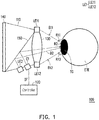
- FIG. 1 illustrates a side view of a head mounted display in an embodiment of the invention.
- a head mounted display 100 includes a tube 110, light beam generators LE1 and LE2, an image capturer C1, a controller 120, a lens 130 and a display panel 140.
- the lens 130 is disposed on a first side of the tube 110 adjacent to a target area TG.
- the display panel 140 is disposed on a second side of the tube 110 away from the target area TG. The first side is opposite to the second side.
- the light beam generator LE1 includes two partial light beam generators LE11 and LE12.
- Each of the partial light beam generators LE11 and LE12 of the light beam generator LE1 may include one or more light emitting diodes.
- said light emitting diode may be an infrared emitting diode.
- the light beam generators LE11 and LE12 are respectively disposed on an upper edge and a lower edge of the lens 130 and respectively project light beams B11 and B12 to surrounding ranges R11 and R12 of the target area TG.
- the light beam generator LE2 is disposed inside the tube 110 and configured to project a light beam B2.
- a reflector 150 is disposed in the tube 110. Through the reflector 150, the light beam generator LE2 may have the light beam B2 reflected and then projected to a center range R2 of the target area TG.
- the light beam generator LE2 includes one or more light emitting diodes, which may be infrared emitting diode(s).
- the reflector 150 may be an infrared reflector.
- the image capturer C1 may be an infrared camera.
- the image capturer C1 is disposed inside the tube 110, and captures image information of the target area TG through the reflector 150.
- the image capturer C1 is coupled to the controller 120, and configured to transmit image information IF to the controller 120.
- the controller 120 may then analyze the image information IF.
- the controller 120 may perform a tracking operation on the eyeball EYE according to the image information IF.
- the controller 120 may be a processor with computing capability.
- the controller 120 may be a hardware circuit designed through Hardware Description Language (HDL) or any other design methods for digital circuit well-known to persons with ordinary skill in the art and may be implemented in from of Field Programmable Gate Array (FPGA), Complex Programmable Logic Device (CPLD) or Application-specific Integrated Circuit (ASIC).
- HDL Hardware Description Language
- FPGA Field Programmable Gate Array
- CPLD Complex Programmable Logic Device
- ASIC Application-specific Integrated Circuit
- an image capturer in a head mounted display 200 may perform an image capturing operation on the eyeball EYE on the target area, and in an ideal state, may obtain image information IF1 as shown in FIG. 3A .
- the image capturer in the head mounted display 200 may perform the image capturing operation on the eyeball EYE on the target area, and may obtain image information IF2 as shown in FIG. 3B .
- image information IF2 as can be clearly seen, it is difficult to recognize a light spot on the eyeball EYE of the user because the brightness is too low at a part of the eyeball EYE.
- the head mounted display 200 can turn on the light beam generator disposed inside the tube to project the light beam B2, and perform the supplementary lighting operation for the center range R2 of the target area through the light beam B2. After the light beam B2 is generated, the head mounted display 200 may capture image information IF3, wherein the brightness at the part of the eyeball EYE in the image information IF3 has been increased.
- a stray light may be generated on the eyeball EYE due to the lens 230.
- the controller of the head mounted display 200 may perform a stray light eliminating operation for the image information IF3, and accordingly obtain image information IF4. Further, the controller may determine a location of the eyeball EYE through a light spot on the eyeball in image information IF4.
- FIG. 4 illustrates a flowchart of the supplementary lighting of the head mounted display in an embodiment of the invention.
- a supplementary lighting setup is started.
- the light beam generator LE2 disposed inside the tube 110 for projecting the light beam B2 to the center range R2 of the target area TG is not turned on. Instead, only the light beam generators LE11 and LE12 for projecting the light beams B11 and B12 to the surrounding ranges R11 and R12 of the target area TG are turned on.
- step S420 three areas are divided according to image information, and a light intensity in image information is calculated. Details of the above may refer to FIG. 1 , FIG.
- FIG. 5 illustrates a schematic diagram of image information in an embodiment of the invention.
- the controller 120 may divide the image information IF into the center range R2 and a surrounding range R1 including two sub ranges RA11 and RA12.
- the center range R2 is between the sub ranges RA11 and RA12.
- the controller 120 may calculate an average light intensity of the center range R2 to obtain an average brightness 12, and calculate average light intensities of the sub ranges RA11 and RA12 to obtain sub brightnesses 11 and 13.
- step S430 when the ratio is less than the preset threshold, the controller 120 may activate the supplementary lighting operation, turn on the light beam generator LE2 disposed inside the tube 110 to project the light beam B2 for a supplementary lighting to the center range R2 of the target area TG, and proceed to execute step S440.
- the ratio is not less than the preset threshold, it is not required to start the supplementary lighting operation, and the supplementary lighting setup may be ended (step S460).
- the preset threshold of this embodiment may be 80%.
- step S440 the image capturer C1 may perform the image capturing operation on the target area TG again, and the controller 120 may then calculate the ratio of the average brightness of the center range R2 to the average brightnesses of the sub ranges RA11 and RA12 according to new image information.
- step S450 the controller 120 performs a brightness adjusting operation on the light beam for the supplementary lighting according to a size of the updated ratio (step S450).
- the updated ratio when the updated ratio is less than 80%, it means that the brightness of the light beam for the supplementary light needs to be increased.
- the updated ratio is greater than 120%, it means that the brightness of the light beam used for the supplementary light needs to be reduced.
- the controller 120 may send a command to drive the light beam generator LE2 to adjust a light intensity (brightness) of the light beam B2.
- FIG. 6 illustrates a flowchart of the eye-tracking function of the head mounted display in an embodiment of the invention.
- step S610 an eye-tracking function is started.
- step S620 the head mounted display 100 may turn on the light beam generator (light emitting diode LED) LE2 disposed inside the tube 110 for the supplementary lighting operation, and turn off the light beam generators (light emitting diode LED) LE11 and LE12 disposed outside the tube 110 for illumination.
- the image capturer C1 captures image information of the eyeball EYE in the target area TG.
- the controller 120 may calculate pupil information (a location and a size of the pupil) according to the image information of the center range that is lit.
- the head mounted display 100 may turn off the light beam generator (light emitting diode LED) LE2 disposed inside the tube 110, and turn on the light beam generators (light emitting diode LED) LE11 and LE12 disposed outside the tube 110.
- step S650 by capturing the image information of the eyeball EYE, light spot information on the eyeball EYE is obtained and a location and a direction of sight of the eyeball are calculated.
- step S660 whether to end the eye-tracking operation is determined. If the eye-tracking operation is not to be ended, step S620 is executed again. The determination of step S660 may be based on whether an eye-tracking requirement of the head mounted display 100 is ended, and the entire process may be ended when the head mounted display 100 no longer needs to track the location of the eyeball of the user.
- the head mounted display of the invention may further calculate the curvature of the cornea of the eyeball of the user and a distance between the eyeball and the lens according to the captured image information.
- FIG. 7 illustrates a schematic diagram of a calculating method for the curvature of the cornea of the eyeball and the distance between the eyeball and the lens.
- a distance D S is provided between a light center C of the image capturer and a screen PA;
- a shortest distance Dc is provided between a connecting line A1 of the light beam generators LE11 and LE12 disposed outside the tube and the light center C;
- a shortest distance D L is provided between the light beam generator LE2 disposed inside the tube and the connecting line A1.
- the image information may be generated on the screen PA, and the image information includes light spot images L 11 *, L 12 * and L 2 *.
- the light spot images L 11 * ,L 12 * and L 2 * respectively correspond to light spots generated on the eyeball EYE by the light beams provided by the light beam generators LE11 and LE12 and the light beam generator LE2.
- the aforementioned distances D S , D C and D L are all known and fixed parameters.
- the cornea of the eyeball EYE is spherical and has a radius of curvature R and a spherical center O.
- a shortest distance D 1 is provided between the eyeball EYE and the connecting line A1 of the light beam generators LE11 and LE12 (which is equal to a distance between a spherical tangent A3 of the eyeball EYE and the connecting line A1).
- the light beams provided by the light beam generators LE11, LE12 and LE2 may be imaged on different locations L 11 ', L 12 ' and L 2 ' in the eyeball EYE.
- the locations L 11 ' and L 12 ' are not coplanar with the location L 2 '.
- a shortest distance D 2 is provided between a connecting line A2 of the locations L 11 ' and L 12 ' and the tangent A3; a shortest distance D 4 is provided between the location L 2 ' and the tangent A3; and a shortest distance D 3 is provided between the tangent A3 and the light beam generator LE2.
- the above distances D 1 to D 4 are all variable parameters.
- the radius of curvature R of the cornea and the distance D 1 may be calculated through an imaging formula.
- a hypothetical plane is set, and the hypothetical plane is parallel to the connecting line A1 and perpendicular to a Z axis.
- the connecting line A2 is positioned on FIG. 7 .
- a first connecting line CL1 is generated according to the light center C and the light spot image L 11 *
- a second connecting line CL2 is generated according to the light center C and the light spot image. Accordingly, an intersection (the location L 11 ') between the first connecting line CL1 and the connecting line A2 and an intersection (the location L 12 ') between the second connecting line CL2 and the connecting line A2 are calculated.
- the spherical center O is an intersection between a connecting line of the location LE11 and the location L 11 ' and a connecting line of the location LE12 and the location L 12 '.
- a shortest distance between the spherical center O and the connecting line A2 may be equal to the radius of curvature R minus the distance D 2 .
- a shortest distance between the connecting lines A1 and A2 is equal to the distance D 1 +the distance D 2 .
- a third connection CL3 is generated according to the light center C and the light spot image L 2 * and an intersection between a connecting line of the spherical center O and the light beam generator LE2 and the connecting line CL3 is calculated to obtain the location L 2 '.
- the distance D 3 the distance D L +the distance D 1
- the connecting line A2 based on the above is hypothetical at the beginning of the calculation and is not necessarily set at the correct position, a further verification need to be performed.
- a vector is generated according to the location L 2 ' and the spherical center O, and an inner product operation is performed on this vector and the Z axis.
- the result of the operation is subtracted (the radius of curvature R-the distance D 4 ) to generate an error value.
- the location of the connecting line A2 may be adjusted and the aforesaid operation may be performed to obtain the new distances D 1 to D 4 and the radius of curvature R until the error value is equal to 0 or less than the tolerance value.
- the head mounted display of this embodiment of the invention can effectively calculate the curvature of the cornea of the eyeball and the distance between the eyeball and the lens, thereby improving the efficiency of eye-tracking.
- the above calculation of the curvature of the cornea of the eyeball and the distance between the eyeball and the lens using the imaging formula are only examples for illustration, and do not limit the scope of the present invention.
- the head mounted display of this embodiment of the invention may also use other calculation methods to obtain the curvature of the cornea of the eyeball and the distance between the eyeball and the lens.
- different light beam generators are provided inside and outside a case of the head mounted display, and the light beam generators project the light beams to the surrounding range and the center range of the target area during the eye-tracking operation, respectively.
- all ranges in the target area can have sufficiently high brightness so that the eye-tracking operation may be effectively performed.
Landscapes
- Physics & Mathematics (AREA)
- Engineering & Computer Science (AREA)
- General Physics & Mathematics (AREA)
- Theoretical Computer Science (AREA)
- Optics & Photonics (AREA)
- General Engineering & Computer Science (AREA)
- Human Computer Interaction (AREA)
- Multimedia (AREA)
- Health & Medical Sciences (AREA)
- General Health & Medical Sciences (AREA)
- Ophthalmology & Optometry (AREA)
- Eye Examination Apparatus (AREA)
Abstract
Description
- The invention relates to a head mounted display, and more particularly, to a head mounted display that can improve eye-tracking accuracy.
- With the advancement of electronic technology, head mounted displays that can provide high-dimensional display capability have become a new trend. The head mounted display can provide a variety of visual experiences such as virtual reality, augmented reality and mixed reality, and has made revolutionary contributions to applications in various fields.
- In the technical field of head mounted displays, tracking the state of the user's eyeballs is an important issue. In the conventional technical field, a light beam can be projected onto the eyeball through a light emitting diode, and an eyeball tracking operation can be performed through a light spot reflected on the eyeball.
- Due to difference head shapes of users, when wearing the head mounted display, a distance between the user's eyeball and an imaging lens of the head mounted display may be different for different users. In such a case, when the user's eyeball is too close to an imaging lens of the head mounted display, the light beam projected by the light emitting diode for tracking the eyeball may only be effectively irradiated to a partial range of the eyeball. As a result, in the case where the partial range is not effectively irradiated by the light beam, the accuracy of the eye-tracking operation performed may be greatly reduced, which reduces the performance of the head mounted display.
- It is an object of the present invention to provide a head mounted display capable of improving eye-tracking accuracy. It is a further object of the present invention to provide a method and a control program for controlling a head mounted display such as to improve eye-tracking accuracy.
- This problem is solved by a head mounted display as claimed by claim 1. Further advantageous embodiments are the subject-matter of the dependent claims.
- The head mounted display of the invention includes a tube, a first light beam generator, a second light beam generator, an image capturer and a controller. The first light beam generator is disposed outside the tube and projects a plurality of first light beams to a first range of a target area. The second light beam generator is disposed inside the tube and projects a second light beam to a second range of the target area. The image capturer captures an image on the target area to generate image information. The controller receives the image information and performs an eye-tracking operation according to the image information. The second range is a center range of the target area, and the first range is a surrounding range of the target area.
- Based on the above, the head mounted display of the invention can project the light beams to the surrounding area and the center area of the target area through the different light beam generators respectively disposed outside and inside the tube. When the target area is too close to the tube, the second light beam generator can project the second light beam to the center range of the target area to increase a brightness of a light spot generated at the center range of the target area, so to improve eye-tracking accuracy.
-
-
FIG. 1 illustrates a side view of a head mounted display in an embodiment of the invention. -
FIG. 2 illustrates a schematic diagram of a head mounted display in an embodiment of the invention. -
FIG. 3A to FIG. 3D illustrate schematic diagrams of a supplementary lighting operation in an embodiment of the invention. -
FIG. 4 illustrates a flowchart of the supplementary lighting operation of the head mounted display in an embodiment of the invention. -
FIG. 5 illustrates a schematic diagram of image information in an embodiment of the invention. -
FIG. 6 illustrates a flowchart of an eye-tracking function of the head mounted display in an emb1odiment of the invention. -
FIG. 7 illustrates a schematic diagram of a calculating method for a curvature of a cornea of an eyeball and a distance between the eyeball and a lens. - Referring to
FIG. 1, FIG. 1 illustrates a side view of a head mounted display in an embodiment of the invention. A head mounteddisplay 100 includes atube 110, light beam generators LE1 and LE2, an image capturer C1, acontroller 120, alens 130 and adisplay panel 140. In this embodiment, thelens 130 is disposed on a first side of thetube 110 adjacent to a target area TG. Thedisplay panel 140 is disposed on a second side of thetube 110 away from the target area TG. The first side is opposite to the second side. - On the other hand, the light beam generator LE1 includes two partial light beam generators LE11 and LE12. Each of the partial light beam generators LE11 and LE12 of the light beam generator LE1 may include one or more light emitting diodes. In this embodiment, said light emitting diode may be an infrared emitting diode. The light beam generators LE11 and LE12 are respectively disposed on an upper edge and a lower edge of the
lens 130 and respectively project light beams B11 and B12 to surrounding ranges R11 and R12 of the target area TG. - In addition, the light beam generator LE2 is disposed inside the
tube 110 and configured to project a light beam B2. In this embodiment, areflector 150 is disposed in thetube 110. Through thereflector 150, the light beam generator LE2 may have the light beam B2 reflected and then projected to a center range R2 of the target area TG. The light beam generator LE2 includes one or more light emitting diodes, which may be infrared emitting diode(s). Thereflector 150 may be an infrared reflector. - The image capturer C1 may be an infrared camera. The image capturer C1 is disposed inside the
tube 110, and captures image information of the target area TG through thereflector 150. The image capturer C1 is coupled to thecontroller 120, and configured to transmit image information IF to thecontroller 120. Thecontroller 120 may then analyze the image information IF. When an eyeball EYE of a user is located on the target area TG, thecontroller 120 may perform a tracking operation on the eyeball EYE according to the image information IF. - In this embodiment, the
controller 120 may be a processor with computing capability. Alternatively, thecontroller 120 may be a hardware circuit designed through Hardware Description Language (HDL) or any other design methods for digital circuit well-known to persons with ordinary skill in the art and may be implemented in from of Field Programmable Gate Array (FPGA), Complex Programmable Logic Device (CPLD) or Application-specific Integrated Circuit (ASIC). - For operation details of the head mounted display in the embodiment of the invention, reference can be made to the schematic diagram of a head mounted display of the embodiment of the invention illustrated in
FIG. 2 and the schematic diagrams of a supplementary lighting operation of the embodiment of the invention illustrated inFIG. 3A to FIG. 3D . InFIG. 2 , an image capturer in a head mounteddisplay 200 may perform an image capturing operation on the eyeball EYE on the target area, and in an ideal state, may obtain image information IF1 as shown inFIG. 3A . - When the eyeball EYE of the user is too close to a
lens 230 of the head mounteddisplay 200, a range covered by light beams projected by the beam generators LE11 and LE12 disposed at edges of thelens 230 cannot effectively cover the center range R2 of the target area on which the eyeball EYE is located. In this case, the image capturer in the head mounteddisplay 200 may perform the image capturing operation on the eyeball EYE on the target area, and may obtain image information IF2 as shown inFIG. 3B . In the image information IF2, as can be clearly seen, it is difficult to recognize a light spot on the eyeball EYE of the user because the brightness is too low at a part of the eyeball EYE. - In this embodiment of the invention, the head mounted
display 200 can turn on the light beam generator disposed inside the tube to project the light beam B2, and perform the supplementary lighting operation for the center range R2 of the target area through the light beam B2. After the light beam B2 is generated, the head mounteddisplay 200 may capture image information IF3, wherein the brightness at the part of the eyeball EYE in the image information IF3 has been increased. - Incidentally, in the image information IF3, a stray light may be generated on the eyeball EYE due to the
lens 230. - Next, in
FIG. 3D , the controller of the head mounteddisplay 200 may perform a stray light eliminating operation for the image information IF3, and accordingly obtain image information IF4. Further, the controller may determine a location of the eyeball EYE through a light spot on the eyeball in image information IF4. - The following refers to
FIG. 1 andFIG. 4 together, andFIG. 4 illustrates a flowchart of the supplementary lighting of the head mounted display in an embodiment of the invention. Here, in step S410, a supplementary lighting setup is started. At this time, in the head mounteddisplay 100, the light beam generator LE2 disposed inside thetube 110 for projecting the light beam B2 to the center range R2 of the target area TG is not turned on. Instead, only the light beam generators LE11 and LE12 for projecting the light beams B11 and B12 to the surrounding ranges R11 and R12 of the target area TG are turned on. Next, in step S420, three areas are divided according to image information, and a light intensity in image information is calculated. Details of the above may refer toFIG. 1 ,FIG. 4 andFIG. 5 together, andFIG. 5 illustrates a schematic diagram of image information in an embodiment of the invention. InFIG. 5 , according to the location of the image information IF, thecontroller 120 may divide the image information IF into the center range R2 and a surrounding range R1 including two sub ranges RA11 and RA12. Here, the center range R2 is between the sub ranges RA11 and RA12. In step S420, thecontroller 120 may calculate an average light intensity of the center range R2 to obtain anaverage brightness 12, and calculate average light intensities of the sub ranges RA11 and RA12 to obtainsub brightnesses 11 and 13. Further, thecontroller 120 may calculate a ratio of twice theaverage brightness 12 to a sum of the sub brightnesses 11 and 13 (=(2∗I2)/(I1+I3)), and determine whether to activate the supplementary lighting operation according to whether the above ratio is less than a preset threshold (step S430). - In step S430, when the ratio is less than the preset threshold, the
controller 120 may activate the supplementary lighting operation, turn on the light beam generator LE2 disposed inside thetube 110 to project the light beam B2 for a supplementary lighting to the center range R2 of the target area TG, and proceed to execute step S440. On the contrary, if the ratio is not less than the preset threshold, it is not required to start the supplementary lighting operation, and the supplementary lighting setup may be ended (step S460). The preset threshold of this embodiment may be 80%. - In step S440, the image capturer C1 may perform the image capturing operation on the target area TG again, and the
controller 120 may then calculate the ratio of the average brightness of the center range R2 to the average brightnesses of the sub ranges RA11 and RA12 according to new image information. Next, in step S450, thecontroller 120 performs a brightness adjusting operation on the light beam for the supplementary lighting according to a size of the updated ratio (step S450). In an embodiment of the invention, when the updated ratio is less than 80%, it means that the brightness of the light beam for the supplementary light needs to be increased. On the other hand, when the updated ratio is greater than 120%, it means that the brightness of the light beam used for the supplementary light needs to be reduced. Corresponding to the above, thecontroller 120 may send a command to drive the light beam generator LE2 to adjust a light intensity (brightness) of the light beam B2. - In the operation of comparing the ratio with 80% and 120%, the values of 80% and 120% are only illustrative examples and are not intended to limit the scope of the invention. Those with ordinary knowledge in this field can set the comparison basis of the ratio according to the actual needs, and there are no specific restrictions.
- The following refers to
FIG. 1 andFIG. 6 together, andFIG. 6 illustrates a flowchart of the eye-tracking function of the head mounted display in an embodiment of the invention. In step S610, an eye-tracking function is started. Next, in step S620, the head mounteddisplay 100 may turn on the light beam generator (light emitting diode LED) LE2 disposed inside thetube 110 for the supplementary lighting operation, and turn off the light beam generators (light emitting diode LED) LE11 and LE12 disposed outside thetube 110 for illumination. Next, in step S630, the image capturer C1 captures image information of the eyeball EYE in the target area TG. Thecontroller 120 may calculate pupil information (a location and a size of the pupil) according to the image information of the center range that is lit. - Next, in step S640, the head mounted
display 100 may turn off the light beam generator (light emitting diode LED) LE2 disposed inside thetube 110, and turn on the light beam generators (light emitting diode LED) LE11 and LE12 disposed outside thetube 110. In step S650, by capturing the image information of the eyeball EYE, light spot information on the eyeball EYE is obtained and a location and a direction of sight of the eyeball are calculated. - In step S660, whether to end the eye-tracking operation is determined. If the eye-tracking operation is not to be ended, step S620 is executed again. The determination of step S660 may be based on whether an eye-tracking requirement of the head mounted
display 100 is ended, and the entire process may be ended when the head mounteddisplay 100 no longer needs to track the location of the eyeball of the user. - More specifically, the head mounted display of the invention may further calculate the curvature of the cornea of the eyeball of the user and a distance between the eyeball and the lens according to the captured image information. Referring to
FIG. 7, FIG. 7 illustrates a schematic diagram of a calculating method for the curvature of the cornea of the eyeball and the distance between the eyeball and the lens. InFIG. 7 , in the image capturer, a distance DS is provided between a light center C of the image capturer and a screen PA; a shortest distance Dc is provided between a connecting line A1 of the light beam generators LE11 and LE12 disposed outside the tube and the light center C; and a shortest distance DL is provided between the light beam generator LE2 disposed inside the tube and the connecting line A1. Here, because the light beam generator LE2 is not coplanar with the light beam generators LE11 and LE12, the distance DL is not equal to 0. The image information may be generated on the screen PA, and the image information includes light spot images L11*, L12* and L2*. The light spot images L11* ,L12* and L2* respectively correspond to light spots generated on the eyeball EYE by the light beams provided by the light beam generators LE11 and LE12 and the light beam generator LE2. The aforementioned distances DS, DC and DL are all known and fixed parameters. - On the other hand, the cornea of the eyeball EYE is spherical and has a radius of curvature R and a spherical center O. A shortest distance D1 is provided between the eyeball EYE and the connecting line A1 of the light beam generators LE11 and LE12 (which is equal to a distance between a spherical tangent A3 of the eyeball EYE and the connecting line A1). Further, the light beams provided by the light beam generators LE11, LE12 and LE2 may be imaged on different locations L11', L12' and L2' in the eyeball EYE. Here, the locations L11' and L12' are not coplanar with the location L2'. In addition, a shortest distance D2 is provided between a connecting line A2 of the locations L11' and L12' and the tangent A3; a shortest distance D4 is provided between the location L2' and the tangent A3; and a shortest distance D3 is provided between the tangent A3 and the light beam generator LE2. The above distances D1 to D4 are all variable parameters.
- In this embodiment of the invention, the radius of curvature R of the cornea and the distance D1 may be calculated through an imaging formula. First, a hypothetical plane is set, and the hypothetical plane is parallel to the connecting line A1 and perpendicular to a Z axis. Next, the connecting line A2 is positioned on
FIG. 7 . A first connecting line CL1 is generated according to the light center C and the light spot image L11*, and a second connecting line CL2 is generated according to the light center C and the light spot image. Accordingly, an intersection (the location L11') between the first connecting line CL1 and the connecting line A2 and an intersection (the location L12') between the second connecting line CL2 and the connecting line A2 are calculated. The spherical center O is an intersection between a connecting line of the location LE11 and the location L11' and a connecting line of the location LE12 and the location L12'. - A shortest distance between the spherical center O and the connecting line A2 may be equal to the radius of curvature R minus the distance D2. A shortest distance between the connecting lines A1 and A2 is equal to the distance D1+the distance D2. According to the imaging formula, a mathematical formula may be obtained as: 1/D1+1/D2=2/R. By solving the simultaneous equations for the above relationship, the distances D1 and D2 and the radius of curvature R may be calculated.
- Then, a third connection CL3 is generated according to the light center C and the light spot image L2* and an intersection between a connecting line of the spherical center O and the light beam generator LE2 and the connecting line CL3 is calculated to obtain the location L2'. Here, the distance D3=the distance DL+the distance D1, and the distance D4 may be obtained according to the imaging formula: 1/D3+1/D4=2/R.
- Because the connecting line A2 based on the above is hypothetical at the beginning of the calculation and is not necessarily set at the correct position, a further verification need to be performed. Here, a vector is generated according to the location L2' and the spherical center O, and an inner product operation is performed on this vector and the Z axis. The result of the operation is subtracted (the radius of curvature R-the distance D4) to generate an error value. When the error value is not equal to 0 or greater than a tolerance value, the location of the connecting line A2 may be adjusted and the aforesaid operation may be performed to obtain the new distances D1 to D4 and the radius of curvature R until the error value is equal to 0 or less than the tolerance value.
- In this way, the head mounted display of this embodiment of the invention can effectively calculate the curvature of the cornea of the eyeball and the distance between the eyeball and the lens, thereby improving the efficiency of eye-tracking.
- The above calculation of the curvature of the cornea of the eyeball and the distance between the eyeball and the lens using the imaging formula are only examples for illustration, and do not limit the scope of the present invention. The head mounted display of this embodiment of the invention may also use other calculation methods to obtain the curvature of the cornea of the eyeball and the distance between the eyeball and the lens.
- In summary, according to the invention, different light beam generators are provided inside and outside a case of the head mounted display, and the light beam generators project the light beams to the surrounding range and the center range of the target area during the eye-tracking operation, respectively. As a result, all ranges in the target area can have sufficiently high brightness so that the eye-tracking operation may be effectively performed.
Claims (12)
- A head mounted display (100), comprising:a tube (110);a first light beam generator (LEI), disposed outside the tube, and projecting a plurality of first light beams (B11) to a first range (R11) of a target area (TG);a second light beam generator (LE2), disposed inside the tube, and projecting a second light beam (B12) to a second range (R12) of the target area (TG);an image capturer (CI), capturing an image on the target area to generate image information (IF); anda controller (120), receiving the image information, and performing an eye-tracking operation according to the image information,wherein the second range is a center range of the target area, and the first range is a surrounding range of the target area.
- The head mounted display according to claim 1, wherein in a first time interval:the first light beam generator (LEI) projects the first light beams to the first range of the target area;the image capturer (C1) captures the image on the target area to generate first image information; andthe controller(120) respectively calculates a first average brightness and a second average brightness of the first range and the second range according to the first image information, and determines whether to drive the second light beam generator to project the second light beam according to the first average brightness and the second average brightness.
- The head mounted display according to claim 2, wherein in a second time interval subsequent to the first time interval:when a ratio of the second average brightness to the first average brightness is less than a threshold, the controller drives the second light beam generator to project the second light beam;the image capturer captures the image on the target area to generate second image information; andthe controller calculates location information of an eyeball on the target area according to the second image information.
- The head mounted display according to claim 3, further comprising:
when the ratio of the second average brightness to the first average brightness is less than the threshold and the second light beam generator is turned on, the second light beam generator increases a brightness of the second light beam. - The head mounted display according to claim 4, wherein in the first time interval, the first light beam generator projects the first light beams to a first sub range and a second sub range of the first range; the controller obtains a first sub brightness 11 and a second sub brightness 13 respectively corresponding to the first sub range and the second sub range; and the controller calculates a ratio of twice the second average brightness 12 to a sum of the first sub brightness 11 and the second sub brightness 13 = (2∗I2)/(I1+I3).
- The head mounted display according to claim 5, wherein the brightness of the second light beam is increased when the ratio is less than 80%.
- The head mounted display according to claim 5, wherein when the ratio is greater than 120%, the second light beam generator reduces the brightness of the second light beam.
- The head mounted display according to any of the preceding claims, wherein in a first time interval:the second light beam generator projects the second light beam to the second range of the target area; the first light beam generator is turned off;the image capturer captures the image on the target area to generate first image information; andthe controller calculates pupil information of an eyeball in the target area according to the first image information; andin a second time interval different from the first time interval:the first light beam generator projects the first light beams to the first range of the target area; the second light beam generator is turned off;the image capturer captures the image on the target area to generate second image information; andthe controller calculates a location and a direction of sight of the eyeball in the target area according to the first image information.
- The head mounted display according to any of the preceding claims, further comprising:a lens (130), disposed on a first side of the tube (110) adjacent to the target area (TG); anda reflector (150), disposed in the tube, and configured to reflect the second light beam to the target area,wherein the first light beam generator (LEI) is disposed on an edge of the lens (130), and the image capturer (C1) captures the image information of the target area through the reflector.
- The head mounted display according to claim 9, wherein the controller (120) further calculates a curvature of a cornea of an eyeball and a distance between the eyeball and the lens according to the image information.
- The head mounted display according to claim 9 or 10, further comprising:
a display panel (140), disposed on a second side of the tube (110) opposite to the first side. - The head mounted display according to any of the preceding claims, wherein the first light beam generator (LEI) comprises a plurality of first infrared transmitters; the second light beam generator (LE2) comprises a plurality of second infrared transmitters; and the image capturer (C1) is an infrared camera.
Applications Claiming Priority (1)
| Application Number | Priority Date | Filing Date | Title |
|---|---|---|---|
| US16/835,309 US20210302726A1 (en) | 2020-03-31 | 2020-03-31 | Head mounted display |
Publications (2)
| Publication Number | Publication Date |
|---|---|
| EP3889668A1 true EP3889668A1 (en) | 2021-10-06 |
| EP3889668B1 EP3889668B1 (en) | 2024-05-01 |
Family
ID=70482351
Family Applications (1)
| Application Number | Title | Priority Date | Filing Date |
|---|---|---|---|
| EP20172356.6A Active EP3889668B1 (en) | 2020-03-31 | 2020-04-30 | Head mounted display |
Country Status (3)
| Country | Link |
|---|---|
| US (1) | US20210302726A1 (en) |
| EP (1) | EP3889668B1 (en) |
| CN (1) | CN113467080A (en) |
Citations (4)
| Publication number | Priority date | Publication date | Assignee | Title |
|---|---|---|---|---|
| US20150035744A1 (en) * | 2013-07-30 | 2015-02-05 | Steve Robbins | Near-eye optic positioning in display devices |
| US8971570B1 (en) * | 2011-11-04 | 2015-03-03 | Google Inc. | Dual LED usage for glint detection |
| US20190012540A1 (en) * | 2017-07-07 | 2019-01-10 | Oculus Vr, Llc | Embedded eye tracker with dichroic mirror |
| WO2019067731A1 (en) * | 2017-09-28 | 2019-04-04 | Zermatt Technologies Llc | Method and device for eye tracking using event camera data |
Family Cites Families (4)
| Publication number | Priority date | Publication date | Assignee | Title |
|---|---|---|---|---|
| EP2237237B1 (en) * | 2009-03-30 | 2013-03-20 | Tobii Technology AB | Eye closure detection using structured illumination |
| EP2238889B1 (en) * | 2009-04-01 | 2011-10-12 | Tobii Technology AB | Adaptive camera and illuminator eyetracker |
| JP6144429B2 (en) * | 2013-12-09 | 2017-06-07 | ゼンソモトリック インストゥルメンツ ゲゼルシャフト ヒューア イノベイティブ ゼンソリック エムベーハーSENSOMOTORIC INSTRUMENTS Gesellschaft fur innovative Sensorik mbH | Eye tracking device operating method and eye tracking device performing active illumination control to improve eye tracking robustness |
| US10705604B2 (en) * | 2018-05-22 | 2020-07-07 | Htc Corporation | Eye tracking apparatus and light source control method thereof |
-
2020
- 2020-03-31 US US16/835,309 patent/US20210302726A1/en not_active Abandoned
- 2020-04-14 CN CN202010289301.6A patent/CN113467080A/en active Pending
- 2020-04-30 EP EP20172356.6A patent/EP3889668B1/en active Active
Patent Citations (4)
| Publication number | Priority date | Publication date | Assignee | Title |
|---|---|---|---|---|
| US8971570B1 (en) * | 2011-11-04 | 2015-03-03 | Google Inc. | Dual LED usage for glint detection |
| US20150035744A1 (en) * | 2013-07-30 | 2015-02-05 | Steve Robbins | Near-eye optic positioning in display devices |
| US20190012540A1 (en) * | 2017-07-07 | 2019-01-10 | Oculus Vr, Llc | Embedded eye tracker with dichroic mirror |
| WO2019067731A1 (en) * | 2017-09-28 | 2019-04-04 | Zermatt Technologies Llc | Method and device for eye tracking using event camera data |
Also Published As
| Publication number | Publication date |
|---|---|
| US20210302726A1 (en) | 2021-09-30 |
| EP3889668B1 (en) | 2024-05-01 |
| CN113467080A (en) | 2021-10-01 |
Similar Documents
| Publication | Publication Date | Title |
|---|---|---|
| TWI714131B (en) | Control method, microprocessor, computer-readable storage medium and computer device | |
| US10503973B2 (en) | Pupil detection device | |
| US10722113B2 (en) | Gaze detection apparatus and gaze detection method | |
| CN107480589B (en) | Infrared light source assembly and electronic device | |
| TWI705354B (en) | Eye tracking apparatus and light source control method thereof | |
| CN110308458B (en) | Adjusting method, adjusting device, terminal and computer readable storage medium | |
| CN113132613A (en) | Camera light supplementing device, electronic equipment and light supplementing method | |
| JP7318793B2 (en) | Biometric authentication device, biometric authentication method, and its program | |
| US12003898B2 (en) | Projector and projection method | |
| JP2018205288A (en) | Distance measuring device, distance measuring method, and program | |
| US10748301B2 (en) | Corneal reflex position detection device, eye-gaze tracking device, and corneal reflex position detection method | |
| US11782268B2 (en) | Eyeball tracking system for near eye display apparatus, and near eye display apparatus | |
| WO2016031666A1 (en) | Line-of-sight detection device | |
| CN115731601A (en) | Eye movement tracking device and method | |
| EP3889668B1 (en) | Head mounted display | |
| EP0687441B1 (en) | Electronic equipment having viewpoint detection apparatus | |
| CN116962891A (en) | Iris image acquisition infrared lamp light supplementing method, device, medium and equipment | |
| WO2018164104A1 (en) | Eye image processing device | |
| TWI725802B (en) | Head mounted display | |
| CN110505407B (en) | Lens focusing method, device and device for infrared imaging equipment | |
| CN113376931B (en) | Fluorescence area light intensity supplementary lighting method, device and system for parathyroid gland detection | |
| WO2017081805A1 (en) | Operation detection device, operation detection method, and video display system | |
| EP3376345B1 (en) | Object tracking arrangements | |
| JP3232873B2 (en) | Gaze direction detection device for vehicles | |
| US11997434B2 (en) | Display method and display system |
Legal Events
| Date | Code | Title | Description |
|---|---|---|---|
| PUAI | Public reference made under article 153(3) epc to a published international application that has entered the european phase |
Free format text: ORIGINAL CODE: 0009012 |
|
| STAA | Information on the status of an ep patent application or granted ep patent |
Free format text: STATUS: THE APPLICATION HAS BEEN PUBLISHED |
|
| AK | Designated contracting states |
Kind code of ref document: A1 Designated state(s): AL AT BE BG CH CY CZ DE DK EE ES FI FR GB GR HR HU IE IS IT LI LT LU LV MC MK MT NL NO PL PT RO RS SE SI SK SM TR |
|
| STAA | Information on the status of an ep patent application or granted ep patent |
Free format text: STATUS: REQUEST FOR EXAMINATION WAS MADE |
|
| 17P | Request for examination filed |
Effective date: 20211112 |
|
| RBV | Designated contracting states (corrected) |
Designated state(s): AL AT BE BG CH CY CZ DE DK EE ES FI FR GB GR HR HU IE IS IT LI LT LU LV MC MK MT NL NO PL PT RO RS SE SI SK SM TR |
|
| STAA | Information on the status of an ep patent application or granted ep patent |
Free format text: STATUS: EXAMINATION IS IN PROGRESS |
|
| 17Q | First examination report despatched |
Effective date: 20220207 |
|
| REG | Reference to a national code |
Ref country code: DE Ref legal event code: R079 Free format text: PREVIOUS MAIN CLASS: G02B0027000000 Ipc: G06V0010141000 Ref document number: 602020029931 Country of ref document: DE |
|
| GRAP | Despatch of communication of intention to grant a patent |
Free format text: ORIGINAL CODE: EPIDOSNIGR1 |
|
| STAA | Information on the status of an ep patent application or granted ep patent |
Free format text: STATUS: GRANT OF PATENT IS INTENDED |
|
| RIC1 | Information provided on ipc code assigned before grant |
Ipc: G06F 3/01 20060101ALI20240201BHEP Ipc: G02B 27/01 20060101ALI20240201BHEP Ipc: G02B 27/00 20060101ALI20240201BHEP Ipc: G06V 40/19 20220101ALI20240201BHEP Ipc: G06V 10/141 20220101AFI20240201BHEP |
|
| GRAS | Grant fee paid |
Free format text: ORIGINAL CODE: EPIDOSNIGR3 |
|
| INTG | Intention to grant announced |
Effective date: 20240227 |
|
| RIN1 | Information on inventor provided before grant (corrected) |
Inventor name: FAN, FU-CHENG Inventor name: XIAO, BO-WEN Inventor name: SHIH, BAO-JEN |
|
| GRAA | (expected) grant |
Free format text: ORIGINAL CODE: 0009210 |
|
| STAA | Information on the status of an ep patent application or granted ep patent |
Free format text: STATUS: THE PATENT HAS BEEN GRANTED |
|
| AK | Designated contracting states |
Kind code of ref document: B1 Designated state(s): AL AT BE BG CH CY CZ DE DK EE ES FI FR GB GR HR HU IE IS IT LI LT LU LV MC MK MT NL NO PL PT RO RS SE SI SK SM TR |
|
| REG | Reference to a national code |
Ref country code: GB Ref legal event code: FG4D |
|
| REG | Reference to a national code |
Ref country code: CH Ref legal event code: EP |
|
| REG | Reference to a national code |
Ref country code: IE Ref legal event code: FG4D |
|
| REG | Reference to a national code |
Ref country code: DE Ref legal event code: R096 Ref document number: 602020029931 Country of ref document: DE |
|
| REG | Reference to a national code |
Ref country code: NL Ref legal event code: FP |
|
| REG | Reference to a national code |
Ref country code: LT Ref legal event code: MG9D |
|
| PG25 | Lapsed in a contracting state [announced via postgrant information from national office to epo] |
Ref country code: IS Free format text: LAPSE BECAUSE OF FAILURE TO SUBMIT A TRANSLATION OF THE DESCRIPTION OR TO PAY THE FEE WITHIN THE PRESCRIBED TIME-LIMIT Effective date: 20240901 |
|
| PG25 | Lapsed in a contracting state [announced via postgrant information from national office to epo] |
Ref country code: BG Free format text: LAPSE BECAUSE OF FAILURE TO SUBMIT A TRANSLATION OF THE DESCRIPTION OR TO PAY THE FEE WITHIN THE PRESCRIBED TIME-LIMIT Effective date: 20240501 |
|
| PG25 | Lapsed in a contracting state [announced via postgrant information from national office to epo] |
Ref country code: HR Free format text: LAPSE BECAUSE OF FAILURE TO SUBMIT A TRANSLATION OF THE DESCRIPTION OR TO PAY THE FEE WITHIN THE PRESCRIBED TIME-LIMIT Effective date: 20240501 Ref country code: FI Free format text: LAPSE BECAUSE OF FAILURE TO SUBMIT A TRANSLATION OF THE DESCRIPTION OR TO PAY THE FEE WITHIN THE PRESCRIBED TIME-LIMIT Effective date: 20240501 |
|
| PG25 | Lapsed in a contracting state [announced via postgrant information from national office to epo] |
Ref country code: GR Free format text: LAPSE BECAUSE OF FAILURE TO SUBMIT A TRANSLATION OF THE DESCRIPTION OR TO PAY THE FEE WITHIN THE PRESCRIBED TIME-LIMIT Effective date: 20240802 |
|
| PG25 | Lapsed in a contracting state [announced via postgrant information from national office to epo] |
Ref country code: PT Free format text: LAPSE BECAUSE OF FAILURE TO SUBMIT A TRANSLATION OF THE DESCRIPTION OR TO PAY THE FEE WITHIN THE PRESCRIBED TIME-LIMIT Effective date: 20240902 |
|
| REG | Reference to a national code |
Ref country code: AT Ref legal event code: MK05 Ref document number: 1683453 Country of ref document: AT Kind code of ref document: T Effective date: 20240501 |
|
| PG25 | Lapsed in a contracting state [announced via postgrant information from national office to epo] |
Ref country code: ES Free format text: LAPSE BECAUSE OF FAILURE TO SUBMIT A TRANSLATION OF THE DESCRIPTION OR TO PAY THE FEE WITHIN THE PRESCRIBED TIME-LIMIT Effective date: 20240501 |
|
| PG25 | Lapsed in a contracting state [announced via postgrant information from national office to epo] |
Ref country code: AT Free format text: LAPSE BECAUSE OF FAILURE TO SUBMIT A TRANSLATION OF THE DESCRIPTION OR TO PAY THE FEE WITHIN THE PRESCRIBED TIME-LIMIT Effective date: 20240501 |
|
| PG25 | Lapsed in a contracting state [announced via postgrant information from national office to epo] |
Ref country code: PL Free format text: LAPSE BECAUSE OF FAILURE TO SUBMIT A TRANSLATION OF THE DESCRIPTION OR TO PAY THE FEE WITHIN THE PRESCRIBED TIME-LIMIT Effective date: 20240501 |
|
| PG25 | Lapsed in a contracting state [announced via postgrant information from national office to epo] |
Ref country code: LV Free format text: LAPSE BECAUSE OF FAILURE TO SUBMIT A TRANSLATION OF THE DESCRIPTION OR TO PAY THE FEE WITHIN THE PRESCRIBED TIME-LIMIT Effective date: 20240501 |
|
| PG25 | Lapsed in a contracting state [announced via postgrant information from national office to epo] |
Ref country code: PT Free format text: LAPSE BECAUSE OF FAILURE TO SUBMIT A TRANSLATION OF THE DESCRIPTION OR TO PAY THE FEE WITHIN THE PRESCRIBED TIME-LIMIT Effective date: 20240902 Ref country code: PL Free format text: LAPSE BECAUSE OF FAILURE TO SUBMIT A TRANSLATION OF THE DESCRIPTION OR TO PAY THE FEE WITHIN THE PRESCRIBED TIME-LIMIT Effective date: 20240501 Ref country code: NO Free format text: LAPSE BECAUSE OF FAILURE TO SUBMIT A TRANSLATION OF THE DESCRIPTION OR TO PAY THE FEE WITHIN THE PRESCRIBED TIME-LIMIT Effective date: 20240801 Ref country code: LV Free format text: LAPSE BECAUSE OF FAILURE TO SUBMIT A TRANSLATION OF THE DESCRIPTION OR TO PAY THE FEE WITHIN THE PRESCRIBED TIME-LIMIT Effective date: 20240501 Ref country code: IS Free format text: LAPSE BECAUSE OF FAILURE TO SUBMIT A TRANSLATION OF THE DESCRIPTION OR TO PAY THE FEE WITHIN THE PRESCRIBED TIME-LIMIT Effective date: 20240901 Ref country code: HR Free format text: LAPSE BECAUSE OF FAILURE TO SUBMIT A TRANSLATION OF THE DESCRIPTION OR TO PAY THE FEE WITHIN THE PRESCRIBED TIME-LIMIT Effective date: 20240501 Ref country code: GR Free format text: LAPSE BECAUSE OF FAILURE TO SUBMIT A TRANSLATION OF THE DESCRIPTION OR TO PAY THE FEE WITHIN THE PRESCRIBED TIME-LIMIT Effective date: 20240802 Ref country code: FI Free format text: LAPSE BECAUSE OF FAILURE TO SUBMIT A TRANSLATION OF THE DESCRIPTION OR TO PAY THE FEE WITHIN THE PRESCRIBED TIME-LIMIT Effective date: 20240501 Ref country code: ES Free format text: LAPSE BECAUSE OF FAILURE TO SUBMIT A TRANSLATION OF THE DESCRIPTION OR TO PAY THE FEE WITHIN THE PRESCRIBED TIME-LIMIT Effective date: 20240501 Ref country code: BG Free format text: LAPSE BECAUSE OF FAILURE TO SUBMIT A TRANSLATION OF THE DESCRIPTION OR TO PAY THE FEE WITHIN THE PRESCRIBED TIME-LIMIT Effective date: 20240501 Ref country code: AT Free format text: LAPSE BECAUSE OF FAILURE TO SUBMIT A TRANSLATION OF THE DESCRIPTION OR TO PAY THE FEE WITHIN THE PRESCRIBED TIME-LIMIT Effective date: 20240501 Ref country code: RS Free format text: LAPSE BECAUSE OF FAILURE TO SUBMIT A TRANSLATION OF THE DESCRIPTION OR TO PAY THE FEE WITHIN THE PRESCRIBED TIME-LIMIT Effective date: 20240801 |
|
| PG25 | Lapsed in a contracting state [announced via postgrant information from national office to epo] |
Ref country code: DK Free format text: LAPSE BECAUSE OF FAILURE TO SUBMIT A TRANSLATION OF THE DESCRIPTION OR TO PAY THE FEE WITHIN THE PRESCRIBED TIME-LIMIT Effective date: 20240501 |
|
| PG25 | Lapsed in a contracting state [announced via postgrant information from national office to epo] |
Ref country code: EE Free format text: LAPSE BECAUSE OF FAILURE TO SUBMIT A TRANSLATION OF THE DESCRIPTION OR TO PAY THE FEE WITHIN THE PRESCRIBED TIME-LIMIT Effective date: 20240501 |
|
| PG25 | Lapsed in a contracting state [announced via postgrant information from national office to epo] |
Ref country code: CZ Free format text: LAPSE BECAUSE OF FAILURE TO SUBMIT A TRANSLATION OF THE DESCRIPTION OR TO PAY THE FEE WITHIN THE PRESCRIBED TIME-LIMIT Effective date: 20240501 |
|
| PG25 | Lapsed in a contracting state [announced via postgrant information from national office to epo] |
Ref country code: RO Free format text: LAPSE BECAUSE OF FAILURE TO SUBMIT A TRANSLATION OF THE DESCRIPTION OR TO PAY THE FEE WITHIN THE PRESCRIBED TIME-LIMIT Effective date: 20240501 Ref country code: SK Free format text: LAPSE BECAUSE OF FAILURE TO SUBMIT A TRANSLATION OF THE DESCRIPTION OR TO PAY THE FEE WITHIN THE PRESCRIBED TIME-LIMIT Effective date: 20240501 |
|
| PG25 | Lapsed in a contracting state [announced via postgrant information from national office to epo] |
Ref country code: SM Free format text: LAPSE BECAUSE OF FAILURE TO SUBMIT A TRANSLATION OF THE DESCRIPTION OR TO PAY THE FEE WITHIN THE PRESCRIBED TIME-LIMIT Effective date: 20240501 |
|
| PG25 | Lapsed in a contracting state [announced via postgrant information from national office to epo] |
Ref country code: SM Free format text: LAPSE BECAUSE OF FAILURE TO SUBMIT A TRANSLATION OF THE DESCRIPTION OR TO PAY THE FEE WITHIN THE PRESCRIBED TIME-LIMIT Effective date: 20240501 Ref country code: SK Free format text: LAPSE BECAUSE OF FAILURE TO SUBMIT A TRANSLATION OF THE DESCRIPTION OR TO PAY THE FEE WITHIN THE PRESCRIBED TIME-LIMIT Effective date: 20240501 Ref country code: RO Free format text: LAPSE BECAUSE OF FAILURE TO SUBMIT A TRANSLATION OF THE DESCRIPTION OR TO PAY THE FEE WITHIN THE PRESCRIBED TIME-LIMIT Effective date: 20240501 Ref country code: EE Free format text: LAPSE BECAUSE OF FAILURE TO SUBMIT A TRANSLATION OF THE DESCRIPTION OR TO PAY THE FEE WITHIN THE PRESCRIBED TIME-LIMIT Effective date: 20240501 Ref country code: DK Free format text: LAPSE BECAUSE OF FAILURE TO SUBMIT A TRANSLATION OF THE DESCRIPTION OR TO PAY THE FEE WITHIN THE PRESCRIBED TIME-LIMIT Effective date: 20240501 Ref country code: CZ Free format text: LAPSE BECAUSE OF FAILURE TO SUBMIT A TRANSLATION OF THE DESCRIPTION OR TO PAY THE FEE WITHIN THE PRESCRIBED TIME-LIMIT Effective date: 20240501 |
|
| REG | Reference to a national code |
Ref country code: DE Ref legal event code: R097 Ref document number: 602020029931 Country of ref document: DE |
|
| PG25 | Lapsed in a contracting state [announced via postgrant information from national office to epo] |
Ref country code: IT Free format text: LAPSE BECAUSE OF FAILURE TO SUBMIT A TRANSLATION OF THE DESCRIPTION OR TO PAY THE FEE WITHIN THE PRESCRIBED TIME-LIMIT Effective date: 20240501 |
|
| PLBE | No opposition filed within time limit |
Free format text: ORIGINAL CODE: 0009261 |
|
| STAA | Information on the status of an ep patent application or granted ep patent |
Free format text: STATUS: NO OPPOSITION FILED WITHIN TIME LIMIT |
|
| 26N | No opposition filed |
Effective date: 20250204 |
|
| PGFP | Annual fee paid to national office [announced via postgrant information from national office to epo] |
Ref country code: NL Payment date: 20250317 Year of fee payment: 6 |
|
| PG25 | Lapsed in a contracting state [announced via postgrant information from national office to epo] |
Ref country code: SI Free format text: LAPSE BECAUSE OF FAILURE TO SUBMIT A TRANSLATION OF THE DESCRIPTION OR TO PAY THE FEE WITHIN THE PRESCRIBED TIME-LIMIT Effective date: 20240501 |
|
| PGFP | Annual fee paid to national office [announced via postgrant information from national office to epo] |
Ref country code: FR Payment date: 20250310 Year of fee payment: 6 |
|
| PGFP | Annual fee paid to national office [announced via postgrant information from national office to epo] |
Ref country code: GB Payment date: 20250306 Year of fee payment: 6 |
|
| PGFP | Annual fee paid to national office [announced via postgrant information from national office to epo] |
Ref country code: DE Payment date: 20250305 Year of fee payment: 6 |
|
| PG25 | Lapsed in a contracting state [announced via postgrant information from national office to epo] |
Ref country code: SE Free format text: LAPSE BECAUSE OF FAILURE TO SUBMIT A TRANSLATION OF THE DESCRIPTION OR TO PAY THE FEE WITHIN THE PRESCRIBED TIME-LIMIT Effective date: 20240501 |
|
| REG | Reference to a national code |
Ref country code: CH Ref legal event code: H13 Free format text: ST27 STATUS EVENT CODE: U-0-0-H10-H13 (AS PROVIDED BY THE NATIONAL OFFICE) Effective date: 20251125 |
|
| PG25 | Lapsed in a contracting state [announced via postgrant information from national office to epo] |
Ref country code: LU Free format text: LAPSE BECAUSE OF NON-PAYMENT OF DUE FEES Effective date: 20250430 |
|
| PG25 | Lapsed in a contracting state [announced via postgrant information from national office to epo] |
Ref country code: MC Free format text: LAPSE BECAUSE OF FAILURE TO SUBMIT A TRANSLATION OF THE DESCRIPTION OR TO PAY THE FEE WITHIN THE PRESCRIBED TIME-LIMIT Effective date: 20240501 |
|
| REG | Reference to a national code |
Ref country code: BE Ref legal event code: MM Effective date: 20250430 |
|
| PG25 | Lapsed in a contracting state [announced via postgrant information from national office to epo] |
Ref country code: BE Free format text: LAPSE BECAUSE OF NON-PAYMENT OF DUE FEES Effective date: 20250430 |
|
| PG25 | Lapsed in a contracting state [announced via postgrant information from national office to epo] |
Ref country code: CH Free format text: LAPSE BECAUSE OF NON-PAYMENT OF DUE FEES Effective date: 20250430 |
|
| PG25 | Lapsed in a contracting state [announced via postgrant information from national office to epo] |
Ref country code: IE Free format text: LAPSE BECAUSE OF NON-PAYMENT OF DUE FEES Effective date: 20250430 |
|
| PG25 | Lapsed in a contracting state [announced via postgrant information from national office to epo] |
Ref country code: CY Free format text: LAPSE BECAUSE OF FAILURE TO SUBMIT A TRANSLATION OF THE DESCRIPTION OR TO PAY THE FEE WITHIN THE PRESCRIBED TIME-LIMIT Effective date: 20240501 |
|
| PG25 | Lapsed in a contracting state [announced via postgrant information from national office to epo] |
Ref country code: LT Free format text: LAPSE BECAUSE OF FAILURE TO SUBMIT A TRANSLATION OF THE DESCRIPTION OR TO PAY THE FEE WITHIN THE PRESCRIBED TIME-LIMIT Effective date: 20240501 |