EP3889657A1 - A splice tray for optical fiber splices and an optical termination box with said splice tray - Google Patents
A splice tray for optical fiber splices and an optical termination box with said splice tray Download PDFInfo
- Publication number
- EP3889657A1 EP3889657A1 EP21162944.9A EP21162944A EP3889657A1 EP 3889657 A1 EP3889657 A1 EP 3889657A1 EP 21162944 A EP21162944 A EP 21162944A EP 3889657 A1 EP3889657 A1 EP 3889657A1
- Authority
- EP
- European Patent Office
- Prior art keywords
- splice
- base
- along
- holders
- tray
- Prior art date
- Legal status (The legal status is an assumption and is not a legal conclusion. Google has not performed a legal analysis and makes no representation as to the accuracy of the status listed.)
- Pending
Links
Images





Classifications
-
- G—PHYSICS
- G02—OPTICS
- G02B—OPTICAL ELEMENTS, SYSTEMS OR APPARATUS
- G02B6/00—Light guides; Structural details of arrangements comprising light guides and other optical elements, e.g. couplings
- G02B6/44—Mechanical structures for providing tensile strength and external protection for fibres, e.g. optical transmission cables
-
- G—PHYSICS
- G02—OPTICS
- G02B—OPTICAL ELEMENTS, SYSTEMS OR APPARATUS
- G02B6/00—Light guides; Structural details of arrangements comprising light guides and other optical elements, e.g. couplings
- G02B6/44—Mechanical structures for providing tensile strength and external protection for fibres, e.g. optical transmission cables
- G02B6/4439—Auxiliary devices
- G02B6/444—Systems or boxes with surplus lengths
- G02B6/4453—Cassettes
- G02B6/4454—Cassettes with splices
-
- G—PHYSICS
- G02—OPTICS
- G02B—OPTICAL ELEMENTS, SYSTEMS OR APPARATUS
- G02B6/00—Light guides; Structural details of arrangements comprising light guides and other optical elements, e.g. couplings
-
- G—PHYSICS
- G02—OPTICS
- G02B—OPTICAL ELEMENTS, SYSTEMS OR APPARATUS
- G02B6/00—Light guides; Structural details of arrangements comprising light guides and other optical elements, e.g. couplings
- G02B6/24—Coupling light guides
Definitions
- the present invention relates to the fields of equipment and components for the installation of optical cables and their optical splices.
- the present invention relates to the field of optical fiber splice trays and optical fiber splice closures and/or boxes.
- optical fiber cables enter into an optical fiber splice closure which includes splice trays configured to retain optical splices.
- the splice trays usually are pivotally connected one another or to a central panel.
- Extra optical fibers are routed and/or coiled in specific areas on the splice trays or externally to the splicing trays.
- Splice trays have a limited area to hold optical splices.
- known solutions allow splice trays to hold splice holders attachable to the tray and stackable on top one another.
- the optical fibers of the fault splice holders have to be moved among all of the fibers on the tray and cut and re-spliced. These operations cause the risk to damage and/or entangle other fibers.
- EP 1929348 B1 discloses a splice tray arrangement including a tray and a splice chip arrangement.
- the splice chip arrangement includes stackable splice chips defining channels for holding splice elements.
- Each of the splice chips includes a mounting arrangement for mounting the splice chip at a mounting location on the tray and a stacking arrangement for mounting the splice chip upon another splice chip.
- US 8385711 B2 discloses splice holders for managing and storing splices between optical fibers in fiber optic hardware and equipment.
- the splice holder includes a base portion and an array of splice holding partitions extending from the base portion.
- the array of splice holding partitions define a plurality of rows for receiving a respective first splice component along a first direction and a plurality of columns intersecting the plurality of fiber rows for receiving a second splice component along a second direction.
- selected pairs of splices holding partitions define a column width and selected pairs of splices holding partitions define a row width.
- the column width is sufficiently greater than the row width to accommodate the second splice component oriented along one of the plurality of columns that could not otherwise be accommodated if oriented along one of the plurality of rows.
- the above-mentioned splices trays provide arrangements able to retain the splices holders without optimizing the available space on the tray and causing the difficulties above mentioned.
- the mounting arrangement permits the splice chip to be secured to a second splice chip in a stacked relationship.
- the mounting arrangement does not provide an easy access to each splice.
- the stacking of chips on a single tray leads to a significant increase of the total height limited to the side wall.
- the mounting arrangement also causes an increase of the complexity in the managing of the splices.
- US 8385711 B2 discloses a single splice holder attached to the tray without effectively optimizing the available space.
- the applicant has tackled the problem of providing a splice tray able to maximize the usage the available space on the tray and at the same time to allow an easy access to the optical splices.
- the Applicant has found that providing a splice tray with slidable splice holders by means of sliding guides projecting from the splice tray itself, optimizes the available space on the tray increasing the number of installable splice holders and guarantees an easy and quick access to the optical fiber and to the optical splices.
- the present invention relates to a splice tray for optical fiber splices comprising a base having a splice area for retaining optical fiber splices and a routing area for passage of optical fibers from and towards the splice area, splice holders arranged on the splice area, each splice holder having holding members configured to hold optical fiber splices, retaining arrangements arranged on the base and configured to retain the splice holders; wherein each retaining arrangement comprises sliding guides projecting from the base and configured to receive and retain one or more splice holders; and each splice holder is slidable relative to the sliding guides along a sliding direction transversal to the base between a retracted position, in which the splice holder is proximate to the base and an extracted position in which the splice holder is spaced apart from the base along the sliding direction.
- the base comprises a connecting member defining a rotation axis to pivotally connect the base to an optical termination box.
- the retaining arrangements are arranged mutually adjacent along a stacking direction transversal to the sliding direction to retain the splice holders mutually adjacent along the stacking direction.
- each splice holder comprises a support base which comprises a first portion and a second portion spaced apart along a first direction transversal to the sliding direction and configured to engage the sliding guides.
- the retaining arrangements are adjacently arranged along the stacking direction in such a way that the support bases of the splice holders are retained in a mutually faced relationship.
- the support bases of the splice holders are retained in a mutually faced and parallel relationship.
- the splice tray comprises locking arrangements configured to selectively lock sliding of the splice holders in the retracted position and in extracted position.
- the locking arrangements comprises first locking elements formed on the sliding guides and second locking elements formed on the splice holders, the first locking elements and the second locking elements being configured to cooperate at least in the retracted position and in the extracted position.
- the first locking elements and the second locking elements are configured to cooperate to selectively retain the splice holder in the retracted position and limit the slide of the splice holder along the sliding direction to lock the splice holder in the extracted position.
- the sliding guides comprise first guiding members and second guiding members projecting from the base along the sliding direction.
- the first guiding members are spaced apart from the second guiding members along a transversal direction perpendicular to the sliding direction to define a receiving area therebetween for receiving the one or more splice holders.
- the first guiding members are mutually spaced apart along a stacking direction transversal to the sliding direction and to the transversal direction; and the second guiding members are mutually spaced apart along the stacking direction.
- the first guiding members and the second guiding members are configured to elastically deform along the transversal direction and generate an elastic force along the transversal direction and directed towards the splice holder upon insertion of the splice holders between the first guiding members and second guiding.
- the holding members comprise parallel holding walls projecting from the support base, each holding wall extending along the first direction and being configured to hold and separate the optical splices.
- the holding walls are mutually spaced apart along the sliding direction to define holding seats therebetween configured to receive the optical splices.
- the present invention relates to an optical termination box comprising a splice tray for optical splices, the splice tray comprising a base having a splice area for retaining optical fiber splices and a routing area for passage of optical fibers from and towards the splice area, splice holders arranged on the splice area, each splice holder having holding members configured to hold optical fiber splices, retaining arrangements arranged on the base and configured to retain the splice holders; each retaining arrangement comprises sliding guides projecting from the base and configured to receive and retain one or more splice holders; and each splice holder is slidable relative to the sliding guides along a sliding direction transversal to the base between a retracted position, in which the splice holder is proximate to the base and an extracted position in which the splice holder is spaced apart from the base along the sliding direction.
- the optical termination box comprises a frame with a bottom wall and one or more side walls projecting from the bottom wall, the bottom wall and the side walls defining a tray area, the splice tray is arranged on the tray area.
- an optical cable is deemed to be any optical cable comprising one or more optical fibers, an outer sheath and, optionally, strength members.
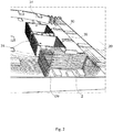
- Figures 1-4 show a splice tray 1 for optical fibers splices 2.
- Figure 8 shows such splice tray 1 associated to an optical termination box 100.
- each fiber splice 2 is typically inserted in a relative splice protector.
- the assembly of a splice combined with a relative splice protector has been indicated as the assembly of a splice combined with a relative splice protector.
- the optical termination box 100 comprises a frame 101 with a bottom wall 102 and side walls 103 projecting from the bottom wall 102.
- the bottom wall 102 and the side walls 103 define a tray area 104 on which a splice trays 1 is arranged.
- each splice tray 1 is pivotally connected to the optical termination box 100. Specifically, each splice tray 1 can reversibly pass from a storage position wherein the splice tray 1 is arranged in the tray area 104 to an operation position wherein the splice tray 1 is rotated and protrudes from the termination box 100.
- the termination box 100 comprises rotation members 105 configured to be associated to a relative splice tray 1 allowing it to rotate from the storage position to the operation position and viceversa.
- the rotation members 105 are associated to one of the sidewalls 103 of the optical termination box 100 as a function of splice tray shape.
- the splice tray 1 comprises a base 10 on which the optical fibers splices 2 are retained, splice holders 20 to hold optical fiber splices 2 and retaining arrangements 30 configured to retain the splice holders 20 on the base 10.
- the base 10 has a splice area 11 wherein the optical fibers splices 2 are retained and a routing area 12 wherein optical fibers 3 can pass through from and towards the splice area 11.
- the splice tray 1 comprises a lateral wall 13 surrounding the splice area 11 and the routing area 12.
- Such lateral wall 13 can project from the base 10 and can be associated to a cover (not shown) to define an inner volume between the base 10, lateral wall 13 and the cover.
- the lateral wall 13 can project from the cover.
- the cover associated to the base 10 defines the inner volume between the base 10, lateral wall 13 and the cover.
- the base 10 comprises one or more openings 14 for receiving optical fibers 3 and allow exit of the optical fibers 3 from the splice tray 1.
- the openings 14 are mutually spaced apart in order to reduce the bend radius of the optical fibers 3 at the retaining arrangements 30.
- the openings 14 can be formed on a same side of lateral wall 13.
- the base 10 comprises routing paths 16 on the routing area 12 that address the optical fibers 3 from the openings 14 to the retaining arrangements 30.
- a connecting member 15 is associated to the base 10 and defines a rotation axis C-C to pivotally connect the base 10 to an optical termination box 100 as shown in figure 8 .
- the connecting member 15 can be connected to the lateral wall 13 between the openings 14.
- the connecting member 15 pivotally connects the base 10 of the splice tray 1 to the frame 101 of the optical termination box 100.
- the connecting member 15 is associated to a relative rotating member 105 of the optical termination box 100 to rotate the slice tray 1.
- each splice tray 1 can rotate around the rotation axis C-C from the storage position to the operation position thanks to the cooperation of the connecting member 15 and the rotation member 105.
- the retaining arrangements 30 are arranged on the base 10 and can be arranged at the splice area 11 of the base 10.
- Each retaining arrangement 30 comprises sliding guides 40.
- the sliding guides 40 project from the base 10 and are configured to receive and retain one or more splice holders 20.
- the sliding guides 40 are configured to allow the splice holders 20 to slide along a sliding direction X-X transversal to the base 10 between a retracted position, in which the splice holder 20 is proximate to the base 10 and an extracted position in which the splice holder 20 is spaced apart from the base 10 along the sliding direction X-X.
- the sliding direction X-X is perpendicular to the base 10.
- the retaining arrangements 30 are arranged mutually adjacent along a stacking direction Y-Y transversal to the sliding direction X-X to retain the splice holders 20 mutually adjacent along the stacking direction Y-Y.
- the sliding guides 40 allow to retain the splice holders 20 along the stacking direction Y-Y and to slide the splice holders 20 along the sliding direction X-X.
- the sliding guides 40 comprise first guiding members 41 and second guiding members 42.
- the first guiding members 41 and the second guiding members 42 projects from the base 10 along the sliding direction X-X. Specifically, the first guiding members 41 and the second guiding members 42 extend along the sliding direction X-X between a first end portion 41a, 42a attached to the base and an opposed second free end portion 41b, 42b.
- the first guiding members 41 are spaced apart from the second guiding members 42 along a transversal direction Z-Z perpendicular to the sliding direction X-X to define a receiving area 46 therebetween for receiving the splice holders 20.
- first guiding members 41 are mutually spaced apart along the stacking direction Y-Y transversal to the sliding direction X-X and to the transversal direction Z-Z as well as the second guiding members 41 are mutually spaced apart along the stacking direction Y-Y.
- first sliding members 41 and the second sliding members 42 spaced apart along the stacking direction Y-Y are arranged mutually adjacent along the stacking direction Y-Y.
- first sliding members 41 and the second sliding members 42 adjacently arranged and mutually spaced apart define respective first sliding seats 44 and second sliding seats 45 therebetween.
- the first sliding seats 44 and the second sliding seats 45 are configured to retain a portion of the splice holders 20 therebetween allowing the sliding of the splice holders 20 along the sliding direction X-X.
- the first guiding members 41 and the second guiding members 42 are configured to elastically deform along the transversal direction Z-Z and generate an elastic force along the transversal direction Z-Z and directed towards the splice holder 20 upon insertion of the splice holder 20 between the first guiding members 41 and second guiding members 42.
- first guiding members 41 and the second guiding members 42 are configured to elastically deform and flex starting from the second free end portions 41b, 42b upon insertion of the splice holder 20 between the first guiding members 41 and second guiding members 42.
- the first guiding members 41 and the second guiding members 42 are elastically deformable so that the second free end portions 41b, 42b mutually space apart along the transversal direction Z-Z upon insertion of splice holders 20 therebetween. Then the first guiding members 41 elastically push the inserted splice holder 20 towards the opposite the second guiding members 42. By this way, the splice holders 20 are guided along the sliding direction X-X and retained along the transversal direction Z-Z and along the stacking direction Y-Y.
- the retaining arrangements 30 are able to firmly retain the splice holders 20 and to improve the gripping effect on the splice holders 20 along the transversal direction Z-Z. Furthermore, the elastic properties of the first guiding members 41 and the second guiding members 42 allow an easy insertion and extraction of the splice holders 20 in and from the retaining arrangements 30 simplifying the maintenance and installation operations.
- the stacking direction Y-Y can be perpendicular to the sliding direction X-X.
- the transversal direction Z-Z can be perpendicular to the sliding direction X-X. It is to be noted that, the transversal direction Z-Z can be perpendicular to the sliding direction X-X and to the stacking direction Y-Y.
- the splice tray 1 comprises one or more arrays 31 of retaining arrangements 30 arranged on the base 10.
- the arrays 31 can be mutually spaced apart along the staking direction Y-Y defining routing channels 32 between them.
- the arrays 31 can also be centered on the base 10 with respect to the lateral wall 13 such that they are surrounded by the routing area 12.
- optical fibers 3 entering the splice tray 1 from the openings 14 are addressed to the retaining arrangements 30 along the routing area 12, specifically, along the routing paths 16.
- the splice holders 20 comprise holding members 21 configured to hold optical fiber splices 2.
- Each splice holder 20 comprises a support base 22 on which the optical fiber splices 2 can be retained.
- Each support base 22 has a first portion 23 and a second portion 24 spaced apart along a first direction A-A transversal to the sliding direction X-X for a width Wb. Specifically, the support base 22 extends between the first portion 23 and the second portion 24 defining end portions of the support base 22. the first portion 23 and the second portion 24 of each splice holder 20 are configured to engage the respective retaining arrangements 30. In other words, each support base 22 engages the respective retaining arrangements 30 at end portions. In detail, the first portion 23 and the second portion 24 of each splice holder 20 are configured to engage respective sliding guides 40.
- each support base 22 comprises a first projecting wing 23a at the first portion 23 and second projecting wing 24a at the second portion 24.
- the first projecting wing 23a and the second projecting wing 24a are configured to be inserted between two adjacent first guiding members 41 and two adjacent second guiding members 42.
- the first projecting wing 23a and the second projecting wing 24a are configured to respectively engage the first sliding seat 44 and the second sliding seat 45 and to allow the slide of the splice holder 20 along the sliding direction X-X.
- the sliding guides 40 allow the passage of the optical fibers 3 to the splice holders 20 avoiding crossover of the optical fibers. Furthermore, such engagement simplifies the sliding of the splice holder 20 and the installation and maintenance operation.
- Each support base 22 has a third portion 25 and a fourth portion 26 mutually spaced apart along a second direction B-B perpendicular to the first direction A-A for a height Hb.
- the second direction B-B is parallel to the sliding direction X-X.
- the third portion 25 faces the base 10, upon insertion of the respective splice holder 20 in the retaining arrangement 30 while the fourth portion 26 is spaced apart from the base 10 upon insertion of the respective splice holder 20 in the retaining arrangement 30.
- each support base 22 can comprise a grip portion 27, for example a tab protruding from the fourth portion 26, configured to be grasped by a user to ease the sliding of the splice holder 20.
- the holding members 21 project from each support base 22 and are configured to hold and separate the optical splices 2 one from the other.
- the holding members 21 can comprise mutually parallel holding walls 21a projecting from the support base 22 along the transversal direction Z-Z. Specifically, the holding walls 21a extend along the first direction A-A.
- the holding walls 21a are mutually spaced apart along the sliding direction X-X to define therebetween holding seats 21b.
- the holding seats 21b receive and hold the optical splices 2 therebetween.
- the holding walls 21a are flexible in order to facilitate the insertion of the optical splices 2 into the holding seats 21b.
- each optical splice 2 is held in a defined position chosen during the installation and maintenance operations. Furthermore, a defined position for the optical splices 2 allow to easily identify an optical splice 2 on the splice tray 1.
- each holding wall 21a can comprise one or more retaining tabs to improve the grip on the optical splices 2 thereby avoiding the optical splices 2 to disengage from the holding members 21.
- Each tab can project from the respective holding wall 21a towards the holding seat 21b.
- the holding members 21 can hold optical splices 2 having different sizes and/or shape. Therefore, the holding walls 21a can be mutually spaced apart in order to receive optical splices 2 having different diameters in a range between 1mm to 2.5mm. Furthermore, the holding walls 21a can be extended along the transversal direction Z-Z in order to hold optical splices 2 having different lengths in range between 30mm to 45mm.
- the splice tray 1 can comprise splice holders 20 adapted to retain different types of optical splice 2.
- the holding members 21 can comprises holding elements configured to act on the ends of the optical splices 2 in order to hold them on the support base 22 thereby reducing the space between adjacent optical splices 2 and therefore increasing the number of optical splices 2 that can be retained by the splice holders 20.
- each splice holder 20 is slidable relative to the sliding guides 40 along the sliding direction X-X between a retracted position, in which the splice holder 20 is proximate to the base 10 and an extracted position in which the splice holder 20 is spaced apart from the base 10 along the sliding direction X-X.
- the third portion 25 is proximal to the base 10
- the extracted position the third portion 25 is spaced apart from the base 10 for a extraction distance De.
- the fourth portion 26 in the retracted position is spaced apart from the base 10 substantially for a distance equal to the height Hb of the support base 22, while in the extracted position the fourth portion 26 is spaced apart from the base 10 for a distance equal to the sum of the height Hb of the support base 22 and the extraction distance De.
- the sliding of the splice holders 20 is limited to the height of the sliding guides 40. Therefore, splice holders 20 can slide along the sliding guides for an extraction distance De in a range between zero and the height of the sliding guides 40.
- the extraction position is to be intended when the extraction distance differs from zero.
- the splice holders 20 allow the access to the holding members 21 when sliding from the retracted position to the extracted position and prevent the access to the holding members 21 when sliding from the extracted position to the retracted position.
- the retaining arrangements 30 are adjacently arranged along the stacking direction Y-Y in such a way that the support bases 22 of the splice holders 20 are retained in a mutually faced relationship. In a further embodiment, the support bases 22 of the splice holders 20 are retained in a mutually faced and parallel relationship.
- splice holders 20 are adjacently stacked along the stacked direction Y-Y transversal to each support base 22 in order to allow a direct access to each splice holder 20 from the fourth portion 26 in the retracted position or in the extracted position. Furthermore, such arrangement allows an independently sliding of each splice holder 20 with respect to the base 10 and with respect to each other.
- splice holders 20 can slide mutually parallel along the sliding direction X-X.
- the splice tray 1 comprises locking arrangements 50 configured to selectively lock sliding of the splice holders 20 in the retracted position and in extracted position.
- the locking arrangements 50 lock the splice holders 20 in the retracted position in order to avoid undesirable sliding of the splice holders 20 with respect to the base 10.
- the locking arrangements 50 lock the splice holders 20 in the extracted position, in order to facilitate operations on the optical fiber splices.
- the locking arrangements 50 comprises first locking elements 51 formed on the sliding guides 40 and second locking elements 52 formed on the splice holders 20.
- the first locking elements 51 and the second locking elements 52 are configured to cooperate in the retracted position and in the extracted position.
- the first locking elements 51 can be arranged at the first portion 23 and at the second portion 24, while the second locking elements 52 can be arranged on the first guiding members 41 and on the second guiding members 42.
- the first locking elements 51 and the second locking elements 52 may be configured to cooperate to selectively retain the splice holders 20 in the retracted position and limit the slide of the splice holders 20 along the sliding direction X-X to lock the splice holders 20 in the extracted position.
- the first locking elements 51 and the second locking elements 52 may be configured to cooperate to lock the splice holders 20 in the retracted position or in the extracted position.
- the first locking elements 51 comprise lower seats 51a and upper seats 51b formed on the first portion 23 and on the second portion 24 of each splice holder 20.
- the lower seats 51a are formed proximal to the third portion 25 and the upper seats 51b are formed proximal to the fourth portion 26.
- the second locking elements 52 comprise first protrusions formed on the first guiding members 41 and second protrusions formed on the second guiding members 42.
- Each first protrusion protrudes from the first guiding member 41 towards the corresponding second guiding member 42 along the traversal direction Z-Z.
- Each second protrusion protrudes from the second guiding member 42 towards the corresponding first guiding member 42 along the traversal direction Z-Z.
- first protrusions and second protrusions are formed at the second free end portions 41b, 42b of the first guiding members 41 and second guiding members 42, substantially at a distance from the base equal to the height of the sliding guides 40.
- the first protrusions are configured to engage the lower seats 51a and upper seats 51b to retain the splice holders 20 respectively in extracted position and in the retracted position.
- the first protrusions may engage the upper seats 51b of a splice holder 20 in the retracted position to prevent sliding of the splice holder 20 along the sliding direction X-X.
- the first protrusions disengage from the upper seats 51b allowing the splice holder 20 to slide. Then, when the first protrusions engage the lower seats 51a of the splice holder 20, the first protrusions stop and limit the sliding of the splice holder 20 in the retracted position.
- the locking arrangement 50 can comprise a plurality of protrusions spaced apart along the first guiding members 41 and the second guiding members 42 and/or relative seats on the splice holders in order to lock the splice holder in extracted positions at different distances from the base.
- first locking elements 51 may comprise one or more protrusions and the second locking elements 52 may comprise one or more seats.
Landscapes
- Physics & Mathematics (AREA)
- General Physics & Mathematics (AREA)
- Optics & Photonics (AREA)
- Light Guides In General And Applications Therefor (AREA)
- Mechanical Coupling Of Light Guides (AREA)
Abstract
Description
- The present invention relates to the fields of equipment and components for the installation of optical cables and their optical splices. In particular, the present invention relates to the field of optical fiber splice trays and optical fiber splice closures and/or boxes.
- Typically, optical fiber cables enter into an optical fiber splice closure which includes splice trays configured to retain optical splices. The splice trays usually are pivotally connected one another or to a central panel. Extra optical fibers are routed and/or coiled in specific areas on the splice trays or externally to the splicing trays.
- Splice trays have a limited area to hold optical splices. Specifically, known solutions allow splice trays to hold splice holders attachable to the tray and stackable on top one another.
- Due to this stackable arrangement, access to the splice holders which are not on the top is difficult and the operators take a lot of time to perform maintenance operations and/or optical fibers installation. Splice holders stacked on top one another, beside causing removal difficulties, do not provide sufficient space to repair the optical splices and locate new splice holders.
- Furthermore, in case of any fault, the optical fibers of the fault splice holders have to be moved among all of the fibers on the tray and cut and re-spliced. These operations cause the risk to damage and/or entangle other fibers.
-
EP 1929348 B1 discloses a splice tray arrangement including a tray and a splice chip arrangement. The splice chip arrangement includes stackable splice chips defining channels for holding splice elements. Each of the splice chips includes a mounting arrangement for mounting the splice chip at a mounting location on the tray and a stacking arrangement for mounting the splice chip upon another splice chip. -
US 8385711 B2 discloses splice holders for managing and storing splices between optical fibers in fiber optic hardware and equipment. The splice holder includes a base portion and an array of splice holding partitions extending from the base portion. In some embodiments the array of splice holding partitions define a plurality of rows for receiving a respective first splice component along a first direction and a plurality of columns intersecting the plurality of fiber rows for receiving a second splice component along a second direction. Similarly, in some embodiments, selected pairs of splices holding partitions define a column width and selected pairs of splices holding partitions define a row width. Additionally, in some embodiments, the column width is sufficiently greater than the row width to accommodate the second splice component oriented along one of the plurality of columns that could not otherwise be accommodated if oriented along one of the plurality of rows. - The above-mentioned splices trays provide arrangements able to retain the splices holders without optimizing the available space on the tray and causing the difficulties above mentioned. Specifically, in
EP 1929348 B1 , the mounting arrangement permits the splice chip to be secured to a second splice chip in a stacked relationship. However, the mounting arrangement does not provide an easy access to each splice. Moreover, the stacking of chips on a single tray leads to a significant increase of the total height limited to the side wall. Furthermore, the mounting arrangement also causes an increase of the complexity in the managing of the splices. On the other hand,US 8385711 B2 discloses a single splice holder attached to the tray without effectively optimizing the available space. - The applicant has tackled the problem of providing a splice tray able to maximize the usage the available space on the tray and at the same time to allow an easy access to the optical splices.
- The Applicant has found that providing a splice tray with slidable splice holders by means of sliding guides projecting from the splice tray itself, optimizes the available space on the tray increasing the number of installable splice holders and guarantees an easy and quick access to the optical fiber and to the optical splices.
- Therefore, the present invention relates to a splice tray for optical fiber splices comprising a base having a splice area for retaining optical fiber splices and a routing area for passage of optical fibers from and towards the splice area, splice holders arranged on the splice area, each splice holder having holding members configured to hold optical fiber splices, retaining arrangements arranged on the base and configured to retain the splice holders; wherein each retaining arrangement comprises sliding guides projecting from the base and configured to receive and retain one or more splice holders; and each splice holder is slidable relative to the sliding guides along a sliding direction transversal to the base between a retracted position, in which the splice holder is proximate to the base and an extracted position in which the splice holder is spaced apart from the base along the sliding direction.
- According to one embodiment, the base comprises a connecting member defining a rotation axis to pivotally connect the base to an optical termination box.
- According to one embodiment, the retaining arrangements are arranged mutually adjacent along a stacking direction transversal to the sliding direction to retain the splice holders mutually adjacent along the stacking direction.
- According to one embodiment, each splice holder comprises a support base which comprises a first portion and a second portion spaced apart along a first direction transversal to the sliding direction and configured to engage the sliding guides.
- According to one embodiment, the retaining arrangements are adjacently arranged along the stacking direction in such a way that the support bases of the splice holders are retained in a mutually faced relationship.
- According to one embodiment, the support bases of the splice holders are retained in a mutually faced and parallel relationship.
- According to one embodiment, the splice tray comprises locking arrangements configured to selectively lock sliding of the splice holders in the retracted position and in extracted position.
- According to one embodiment, the locking arrangements comprises first locking elements formed on the sliding guides and second locking elements formed on the splice holders, the first locking elements and the second locking elements being configured to cooperate at least in the retracted position and in the extracted position.
- According to one embodiment, the first locking elements and the second locking elements are configured to cooperate to selectively retain the splice holder in the retracted position and limit the slide of the splice holder along the sliding direction to lock the splice holder in the extracted position.
- According to one embodiment, the sliding guides comprise first guiding members and second guiding members projecting from the base along the sliding direction.
- According to one embodiment, the first guiding members are spaced apart from the second guiding members along a transversal direction perpendicular to the sliding direction to define a receiving area therebetween for receiving the one or more splice holders.
- According to one embodiment, the first guiding members are mutually spaced apart along a stacking direction transversal to the sliding direction and to the transversal direction; and the second guiding members are mutually spaced apart along the stacking direction.
- According to one embodiment, the first guiding members and the second guiding members are configured to elastically deform along the transversal direction and generate an elastic force along the transversal direction and directed towards the splice holder upon insertion of the splice holders between the first guiding members and second guiding.
- According to one embodiment, the holding members comprise parallel holding walls projecting from the support base, each holding wall extending along the first direction and being configured to hold and separate the optical splices.
- According to one embodiment, the holding walls are mutually spaced apart along the sliding direction to define holding seats therebetween configured to receive the optical splices.
- According to a further aspect, the present invention relates to an optical termination box comprising a splice tray for optical splices, the splice tray comprising a base having a splice area for retaining optical fiber splices and a routing area for passage of optical fibers from and towards the splice area, splice holders arranged on the splice area, each splice holder having holding members configured to hold optical fiber splices, retaining arrangements arranged on the base and configured to retain the splice holders; each retaining arrangement comprises sliding guides projecting from the base and configured to receive and retain one or more splice holders; and each splice holder is slidable relative to the sliding guides along a sliding direction transversal to the base between a retracted position, in which the splice holder is proximate to the base and an extracted position in which the splice holder is spaced apart from the base along the sliding direction.
- According to one embodiment, the optical termination box comprises a frame with a bottom wall and one or more side walls projecting from the bottom wall, the bottom wall and the side walls defining a tray area, the splice tray is arranged on the tray area.
- The present invention will now be described in more detail hereinafter with reference to the accompanying drawings, in which some embodiments of the invention are shown.
-
FIG. 1 is a perspective view of a splice tray according to one embodiment of the present invention, with splice holders in retracted position; -
FIG. 2 is a perspective view of a splice tray according to one embodiment of the present invention, with at least a splice holder in extracted position; -
FIG. 3 is a top view of the splice tray ofFIG. 1 ; -
FIG. 4 is a side view a of the splice tray ofFIG. 2 ; -
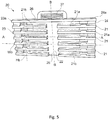
FIG. 5 is a first perspective view of a splice holder according to one embodiment of the present invention; -
FIG. 6 is a second perspective view of a splice holder according to one embodiment of the present invention; -
FIG. 7 is a perspective view of a detail of a splice tray according to one embodiment of the present invention; -
FIG. 8 is a perspective view of an optical termination box according to one embodiment of the present invention. - For the purpose of the present invention, an optical cable is deemed to be any optical cable comprising one or more optical fibers, an outer sheath and, optionally, strength members.
-
Figures 1-4 show asplice tray 1 foroptical fibers splices 2.Figure 8 showssuch splice tray 1 associated to anoptical termination box 100. It is to be noted that eachfiber splice 2 is typically inserted in a relative splice protector. For simplicity, in the following fiber splice has been indicated as the assembly of a splice combined with a relative splice protector. - The
optical termination box 100 comprises aframe 101 with abottom wall 102 andside walls 103 projecting from thebottom wall 102. Thebottom wall 102 and theside walls 103 define atray area 104 on which asplice trays 1 is arranged. - According to one embodiment, each
splice tray 1 is pivotally connected to theoptical termination box 100. Specifically, eachsplice tray 1 can reversibly pass from a storage position wherein thesplice tray 1 is arranged in thetray area 104 to an operation position wherein thesplice tray 1 is rotated and protrudes from thetermination box 100. - Thanks to the rotation of the
splice tray 1 in the operation position, the operations on thesplice tray 1 are facilitated. - According to one embodiment, the
termination box 100 comprisesrotation members 105 configured to be associated to arelative splice tray 1 allowing it to rotate from the storage position to the operation position and viceversa. Therotation members 105 are associated to one of thesidewalls 103 of theoptical termination box 100 as a function of splice tray shape. - The
splice tray 1 comprises a base 10 on which the optical fibers splices 2 are retained,splice holders 20 to hold optical fiber splices 2 and retainingarrangements 30 configured to retain thesplice holders 20 on thebase 10. - According to one embodiment, the
base 10 has asplice area 11 wherein the optical fibers splices 2 are retained and arouting area 12 whereinoptical fibers 3 can pass through from and towards thesplice area 11. - The
splice tray 1 comprises alateral wall 13 surrounding thesplice area 11 and therouting area 12. Suchlateral wall 13 can project from thebase 10 and can be associated to a cover (not shown) to define an inner volume between the base 10,lateral wall 13 and the cover. - Alternatively, the
lateral wall 13 can project from the cover. In this way, the cover associated to thebase 10 defines the inner volume between the base 10,lateral wall 13 and the cover. - According to one embodiment, the
base 10 comprises one ormore openings 14 for receivingoptical fibers 3 and allow exit of theoptical fibers 3 from thesplice tray 1. Specifically, theopenings 14 are mutually spaced apart in order to reduce the bend radius of theoptical fibers 3 at the retainingarrangements 30. It is to be noted that theopenings 14 can be formed on a same side oflateral wall 13. In detail, thebase 10 comprises routingpaths 16 on therouting area 12 that address theoptical fibers 3 from theopenings 14 to the retainingarrangements 30. - According to one embodiment, a connecting
member 15 is associated to thebase 10 and defines a rotation axis C-C to pivotally connect the base 10 to anoptical termination box 100 as shown infigure 8 . The connectingmember 15 can be connected to thelateral wall 13 between theopenings 14. Specifically, the connectingmember 15 pivotally connects thebase 10 of thesplice tray 1 to theframe 101 of theoptical termination box 100. In details, the connectingmember 15 is associated to a relative rotatingmember 105 of theoptical termination box 100 to rotate theslice tray 1. In detail, eachsplice tray 1 can rotate around the rotation axis C-C from the storage position to the operation position thanks to the cooperation of the connectingmember 15 and therotation member 105. - The retaining
arrangements 30 are arranged on thebase 10 and can be arranged at thesplice area 11 of thebase 10. - Each retaining
arrangement 30 comprises sliding guides 40. - The sliding guides 40 project from the
base 10 and are configured to receive and retain one ormore splice holders 20. - The sliding guides 40 are configured to allow the
splice holders 20 to slide along a sliding direction X-X transversal to the base 10 between a retracted position, in which thesplice holder 20 is proximate to thebase 10 and an extracted position in which thesplice holder 20 is spaced apart from thebase 10 along the sliding direction X-X. - According to one embodiment, the sliding direction X-X is perpendicular to the
base 10. - According to one embodiment, the retaining
arrangements 30 are arranged mutually adjacent along a stacking direction Y-Y transversal to the sliding direction X-X to retain thesplice holders 20 mutually adjacent along the stacking direction Y-Y. - In this way, the sliding
guides 40 allow to retain thesplice holders 20 along the stacking direction Y-Y and to slide thesplice holders 20 along the sliding direction X-X. - According to one embodiment, the sliding
guides 40 comprise first guidingmembers 41 and second guidingmembers 42. - The
first guiding members 41 and thesecond guiding members 42 projects from thebase 10 along the sliding direction X-X. Specifically, thefirst guiding members 41 and thesecond guiding members 42 extend along the sliding direction X-X between afirst end portion 41a, 42a attached to the base and an opposed secondfree end portion 41b, 42b. - The
first guiding members 41 are spaced apart from thesecond guiding members 42 along a transversal direction Z-Z perpendicular to the sliding direction X-X to define a receivingarea 46 therebetween for receiving thesplice holders 20. - Moreover, the
first guiding members 41 are mutually spaced apart along the stacking direction Y-Y transversal to the sliding direction X-X and to the transversal direction Z-Z as well as thesecond guiding members 41 are mutually spaced apart along the stacking direction Y-Y. In other words, the first slidingmembers 41 and the second slidingmembers 42 spaced apart along the stacking direction Y-Y are arranged mutually adjacent along the stacking direction Y-Y. - Specifically, the first sliding
members 41 and the second slidingmembers 42 adjacently arranged and mutually spaced apart define respective first slidingseats 44 and second sliding seats 45 therebetween. - The first sliding
seats 44 and the second sliding seats 45 are configured to retain a portion of thesplice holders 20 therebetween allowing the sliding of thesplice holders 20 along the sliding direction X-X. - According to one embodiment, the
first guiding members 41 and thesecond guiding members 42 are configured to elastically deform along the transversal direction Z-Z and generate an elastic force along the transversal direction Z-Z and directed towards thesplice holder 20 upon insertion of thesplice holder 20 between thefirst guiding members 41 and second guidingmembers 42. - Specifically, the
first guiding members 41 and thesecond guiding members 42 are configured to elastically deform and flex starting from the secondfree end portions 41b, 42b upon insertion of thesplice holder 20 between thefirst guiding members 41 and second guidingmembers 42. - Therefore, the
first guiding members 41 and thesecond guiding members 42 are elastically deformable so that the secondfree end portions 41b, 42b mutually space apart along the transversal direction Z-Z upon insertion ofsplice holders 20 therebetween. Then thefirst guiding members 41 elastically push the insertedsplice holder 20 towards the opposite thesecond guiding members 42. By this way, thesplice holders 20 are guided along the sliding direction X-X and retained along the transversal direction Z-Z and along the stacking direction Y-Y. - Thanks to the elastic properties of the
first guiding members 41 and thesecond guiding members 42, the retainingarrangements 30 are able to firmly retain thesplice holders 20 and to improve the gripping effect on thesplice holders 20 along the transversal direction Z-Z. Furthermore, the elastic properties of thefirst guiding members 41 and thesecond guiding members 42 allow an easy insertion and extraction of thesplice holders 20 in and from the retainingarrangements 30 simplifying the maintenance and installation operations. - According to one embodiment, the stacking direction Y-Y can be perpendicular to the sliding direction X-X. The transversal direction Z-Z can be perpendicular to the sliding direction X-X. It is to be noted that, the transversal direction Z-Z can be perpendicular to the sliding direction X-X and to the stacking direction Y-Y.
- According to one embodiment, as shown in
figures 1-4 , thesplice tray 1 comprises one ormore arrays 31 of retainingarrangements 30 arranged on thebase 10. Thearrays 31 can be mutually spaced apart along the staking direction Y-Y definingrouting channels 32 between them. Thearrays 31 can also be centered on the base 10 with respect to thelateral wall 13 such that they are surrounded by therouting area 12. - Accordingly, the
optical fibers 3 entering thesplice tray 1 from theopenings 14 are addressed to the retainingarrangements 30 along therouting area 12, specifically, along therouting paths 16. - The
splice holders 20 comprise holdingmembers 21 configured to hold optical fiber splices 2. - Each
splice holder 20 comprises asupport base 22 on which the optical fiber splices 2 can be retained. - Each
support base 22 has afirst portion 23 and asecond portion 24 spaced apart along a first direction A-A transversal to the sliding direction X-X for a width Wb. Specifically, thesupport base 22 extends between thefirst portion 23 and thesecond portion 24 defining end portions of thesupport base 22. thefirst portion 23 and thesecond portion 24 of eachsplice holder 20 are configured to engage therespective retaining arrangements 30. In other words, eachsupport base 22 engages therespective retaining arrangements 30 at end portions. In detail, thefirst portion 23 and thesecond portion 24 of eachsplice holder 20 are configured to engage respective sliding guides 40. - According to one embodiment, each
support base 22 comprises a first projectingwing 23a at thefirst portion 23 and second projectingwing 24a at thesecond portion 24. The first projectingwing 23a and the second projectingwing 24a are configured to be inserted between two adjacent first guidingmembers 41 and two adjacent second guidingmembers 42. Specifically, the first projectingwing 23a and the second projectingwing 24a are configured to respectively engage the first slidingseat 44 and the second sliding seat 45 and to allow the slide of thesplice holder 20 along the sliding direction X-X. - Thanks to the engagement between the first projecting
wings 23a and the second projectingwings 24a and the first slidingseats 44 and the second sliding seats 45, the slidingguides 40 allow the passage of theoptical fibers 3 to thesplice holders 20 avoiding crossover of the optical fibers. Furthermore, such engagement simplifies the sliding of thesplice holder 20 and the installation and maintenance operation. - Each
support base 22 has athird portion 25 and afourth portion 26 mutually spaced apart along a second direction B-B perpendicular to the first direction A-A for a height Hb. Specifically, the second direction B-B is parallel to the sliding direction X-X. By this arrangement, thethird portion 25 faces thebase 10, upon insertion of therespective splice holder 20 in the retainingarrangement 30 while thefourth portion 26 is spaced apart from the base 10 upon insertion of therespective splice holder 20 in the retainingarrangement 30. - It is to be noted, that each
support base 22 can comprise agrip portion 27, for example a tab protruding from thefourth portion 26, configured to be grasped by a user to ease the sliding of thesplice holder 20. - According to one embodiment, the holding
members 21 project from eachsupport base 22 and are configured to hold and separate theoptical splices 2 one from the other. The holdingmembers 21 can comprise mutuallyparallel holding walls 21a projecting from thesupport base 22 along the transversal direction Z-Z. Specifically, the holdingwalls 21a extend along the first direction A-A. The holdingwalls 21a are mutually spaced apart along the sliding direction X-X to define therebetween holdingseats 21b. The holdingseats 21b receive and hold theoptical splices 2 therebetween. In detail, the holdingwalls 21a are flexible in order to facilitate the insertion of theoptical splices 2 into the holdingseats 21b. - Thanks to the holding
members 21, eachoptical splice 2 is held in a defined position chosen during the installation and maintenance operations. Furthermore, a defined position for theoptical splices 2 allow to easily identify anoptical splice 2 on thesplice tray 1. - In detail, each holding
wall 21a can comprise one or more retaining tabs to improve the grip on theoptical splices 2 thereby avoiding theoptical splices 2 to disengage from the holdingmembers 21. Each tab can project from therespective holding wall 21a towards the holdingseat 21b. - The holding
members 21 can holdoptical splices 2 having different sizes and/or shape. Therefore, the holdingwalls 21a can be mutually spaced apart in order to receiveoptical splices 2 having different diameters in a range between 1mm to 2.5mm. Furthermore, the holdingwalls 21a can be extended along the transversal direction Z-Z in order to holdoptical splices 2 having different lengths in range between 30mm to 45mm. - According to one embodiment, the
splice tray 1 can comprisesplice holders 20 adapted to retain different types ofoptical splice 2. - According to an alternative embodiment, the holding
members 21 can comprises holding elements configured to act on the ends of theoptical splices 2 in order to hold them on thesupport base 22 thereby reducing the space between adjacentoptical splices 2 and therefore increasing the number ofoptical splices 2 that can be retained by thesplice holders 20. - According to one embodiment, each
splice holder 20 is slidable relative to the slidingguides 40 along the sliding direction X-X between a retracted position, in which thesplice holder 20 is proximate to thebase 10 and an extracted position in which thesplice holder 20 is spaced apart from thebase 10 along the sliding direction X-X. Specifically, in the retracted position thethird portion 25 is proximal to thebase 10, while in the extracted position thethird portion 25 is spaced apart from thebase 10 for a extraction distance De. In other words, thefourth portion 26 in the retracted position is spaced apart from the base 10 substantially for a distance equal to the height Hb of thesupport base 22, while in the extracted position thefourth portion 26 is spaced apart from thebase 10 for a distance equal to the sum of the height Hb of thesupport base 22 and the extraction distance De. - Furthermore, the sliding of the
splice holders 20 is limited to the height of the sliding guides 40. Therefore,splice holders 20 can slide along the sliding guides for an extraction distance De in a range between zero and the height of the sliding guides 40. - For the purpose of the present invention, the extraction position is to be intended when the extraction distance differs from zero.
- It is to be noted that the
splice holders 20 allow the access to the holdingmembers 21 when sliding from the retracted position to the extracted position and prevent the access to the holdingmembers 21 when sliding from the extracted position to the retracted position. - According to one embodiment, the retaining
arrangements 30 are adjacently arranged along the stacking direction Y-Y in such a way that the support bases 22 of thesplice holders 20 are retained in a mutually faced relationship. In a further embodiment, the support bases 22 of thesplice holders 20 are retained in a mutually faced and parallel relationship. - Accordingly,
splice holders 20 are adjacently stacked along the stacked direction Y-Y transversal to eachsupport base 22 in order to allow a direct access to eachsplice holder 20 from thefourth portion 26 in the retracted position or in the extracted position. Furthermore, such arrangement allows an independently sliding of eachsplice holder 20 with respect to thebase 10 and with respect to each other. - With this arrangement,
splice holders 20 can slide mutually parallel along the sliding direction X-X. - According to one embodiment, the
splice tray 1 comprises lockingarrangements 50 configured to selectively lock sliding of thesplice holders 20 in the retracted position and in extracted position. The lockingarrangements 50 lock thesplice holders 20 in the retracted position in order to avoid undesirable sliding of thesplice holders 20 with respect to thebase 10. Moreover, the lockingarrangements 50 lock thesplice holders 20 in the extracted position, in order to facilitate operations on the optical fiber splices. - The locking
arrangements 50 comprises first lockingelements 51 formed on the slidingguides 40 andsecond locking elements 52 formed on thesplice holders 20. Thefirst locking elements 51 and thesecond locking elements 52 are configured to cooperate in the retracted position and in the extracted position. Thefirst locking elements 51 can be arranged at thefirst portion 23 and at thesecond portion 24, while thesecond locking elements 52 can be arranged on thefirst guiding members 41 and on thesecond guiding members 42. - The
first locking elements 51 and thesecond locking elements 52 may be configured to cooperate to selectively retain thesplice holders 20 in the retracted position and limit the slide of thesplice holders 20 along the sliding direction X-X to lock thesplice holders 20 in the extracted position. - The
first locking elements 51 and thesecond locking elements 52 may be configured to cooperate to lock thesplice holders 20 in the retracted position or in the extracted position. - According to one embodiment, as shown in
figures 6 and7 , thefirst locking elements 51 compriselower seats 51a andupper seats 51b formed on thefirst portion 23 and on thesecond portion 24 of eachsplice holder 20. - In detail, the
lower seats 51a are formed proximal to thethird portion 25 and theupper seats 51b are formed proximal to thefourth portion 26. - The
second locking elements 52 comprise first protrusions formed on thefirst guiding members 41 and second protrusions formed on thesecond guiding members 42. - It is to be noted that, in view of the symmetry of the
splice tray 1, only the first protrusions are shown in the figures. - Each first protrusion protrudes from the first guiding
member 41 towards the corresponding second guidingmember 42 along the traversal direction Z-Z. - Each second protrusion protrudes from the second guiding
member 42 towards the corresponding first guidingmember 42 along the traversal direction Z-Z. - It is to be noted that the first protrusions and second protrusions are formed at the second
free end portions 41b, 42b of thefirst guiding members 41 and second guidingmembers 42, substantially at a distance from the base equal to the height of the sliding guides 40. - Hereinafter, for sake of conciseness, reference is made to the features of the first protrusions.
- The first protrusions are configured to engage the
lower seats 51a andupper seats 51b to retain thesplice holders 20 respectively in extracted position and in the retracted position. - The first protrusions may engage the
upper seats 51b of asplice holder 20 in the retracted position to prevent sliding of thesplice holder 20 along the sliding direction X-X. - With the
splice holder 20 in the retracted position, upon application of an external force on thesplice holder 20 directed along the sliding direction X-X away from thebase 10, the first protrusions disengage from theupper seats 51b allowing thesplice holder 20 to slide. Then, when the first protrusions engage thelower seats 51a of thesplice holder 20, the first protrusions stop and limit the sliding of thesplice holder 20 in the retracted position. - According to one embodiment, thanks to the locking
arrangements 50 and the elastic properties of thefirst guiding members 41 and thesecond guiding members 42, mutual engagement and disengagement of thefirst locking elements 51 and thesecond locking elements 52 is guaranteed. - According to an alternative embodiment, the locking
arrangement 50 can comprise a plurality of protrusions spaced apart along thefirst guiding members 41 and thesecond guiding members 42 and/or relative seats on the splice holders in order to lock the splice holder in extracted positions at different distances from the base. - According to a further alternative embodiment, the
first locking elements 51 may comprise one or more protrusions and thesecond locking elements 52 may comprise one or more seats.
Claims (15)
- A splice tray (1) for optical fiber splices (2) comprising:- a base (10) having a splice area (11) for retaining optical fiber splices (2) and a routing area (12) for passage of optical fibers (3) from and towards the splice area (11);- splice holders (20) arranged on the splice area (11), each splice holder (20) having holding members (21) configured to hold optical fiber splices (2);- retaining arrangements (30) arranged on the base (10) and configured to retain the splice holders (20);wherein:- each retaining arrangement (30) comprises sliding guides (40) projecting from the base (10) and configured to receive and retain one or more splice holders (20); and- each splice holder (20) is slidable relative to the sliding guides (40) along a sliding direction (X-X) transversal to the base (10) between a retracted position, in which the splice holder (20) is proximate to the base (10) and an extracted position in which the splice holder (20) is spaced apart from the base (10) along the sliding direction (X-X).
- The splice tray (1) according to claim 1, the base (10) comprises a connecting member (15) defining a rotation axis (C-C) to pivotally connect the base (10) to an optical termination box (100).
- The splice tray (1) according to claim 1 or 2, wherein the retaining arrangements (30) are arranged mutually adjacent along a stacking direction (Y-Y) transversal to the sliding direction (X-X) to retain the splice holders (20) mutually adjacent along the stacking direction (Y-Y).
- The splice tray (1) according to claim 3, wherein each splice holder (20) comprises a support base (22) which comprises a first portion (23) and a second portion (24) spaced apart along a first direction (A-A) transversal to the sliding direction (X-X) and configured to engage the sliding guides (40).
- The splice tray (1) according to claim 4, wherein the retaining arrangements (30) are adjacently arranged along the stacking direction (Y-Y) in such a way that the support bases (22) of the splice holders (20) are retained in a mutually faced relationship.
- The splice tray (1) according to claim 5, wherein the support bases (22) of the splice holders (20) are retained in a mutually faced and parallel relationship.
- The splice tray (1) according to any claims 1 to 6, wherein the splice tray (1) comprises locking arrangements (50) configured to selectively lock sliding of the splice holders (20) in the retracted position and in extracted position.
- The splice tray (1) according to claim 7, wherein the locking arrangements (50) comprises first locking elements (51) formed on the sliding guides (40) and second locking elements (52) formed on the splice holders (20), the first locking elements and the second locking elements being configured to cooperate at least in the retracted position and in the extracted position.
- The splice tray (1) according to claim 8, wherein the first locking elements (51) and the second locking elements (52) are configured to cooperate to selectively retain the splice holders (20) in the retracted position and limit the slide of the splice holders (20) along the sliding direction (X-X) to lock the splice holders (20) in the extracted position.
- The splice tray (1) according to any claims 1 to 9, wherein the sliding guides (40) comprise first guiding members (41) and second guiding members (42) projecting from the base (10) along the sliding direction (X-X), the first guiding members (41) being spaced apart from the second guiding members (42) along a transversal direction (Z-Z) perpendicular to the sliding direction (X-X) to define a receiving area (43) therebetween for receiving the one or more splice holders (20).
- The splice tray (1) according to claim 9 or 10, wherein- the first guiding members (41) are mutually spaced apart along a stacking direction (Y-Y) transversal to the sliding direction (X-X) and to the transversal direction (Z-Z); and- the second guiding members (41) are mutually spaced apart along the stacking direction (Y-Y).
- The splice tray (1) according to any claims 9 to 11, wherein the first guiding members (41) and the second guiding members (42) are configured to elastically deform along the transversal direction (Z-Z) and generate an elastic force along the transversal direction (Z-Z) and directed towards the splice holder (20) upon insertion of the splice holders (20) between the first guiding members (41) and second guiding members (42).
- The splice tray (1) according to any claims 4 to 12, wherein the holding members (21) comprise parallel holding walls (21a) projecting from the support base (22), each holding wall (21a) extending along the first direction (A-A) and being configured to hold and separate the optical splices (2).
- An optical termination box (100) comprising a splice tray (1) for optical splices (2), the splice tray (1) comprising:- a base (10) having a splice area (11) for retaining optical fiber splices (2) and a routing area (12) for passage of optical fibers (3) from and towards the splice area (11);- splice holders (20) arranged on the splice area (11), each splice holder (20) having holding members (21) configured to hold optical fiber splices (2);- retaining arrangements (30) arranged on the base (10) and configured to retain the splice holders (20);wherein:- each retaining arrangement (30) comprises sliding guides (40) projecting from the base (10) and configured to receive and retain one or more splice holders (20); and- each splice holder (20) is slidable relative to the sliding guides (40) along a sliding direction (X-X) transversal to the base (10) between a retracted position, in which the splice holder (20) is proximate to the base (10) and an extracted position in which the splice holder (20) is spaced apart from the base (10) along the sliding direction (X-X).
- The optical termination box (100) according to claim 14, wherein the optical termination box (100) comprises a frame (101) with a bottom wall (102) and one or more side walls (103) projecting from the bottom wall (102), the bottom wall (102) and the side walls (103) defining a tray area (104), the splice tray (1) is arranged on the tray area (104).
Applications Claiming Priority (1)
| Application Number | Priority Date | Filing Date | Title |
|---|---|---|---|
| IT102020000007045A IT202000007045A1 (en) | 2020-04-02 | 2020-04-02 | Tray for fiber optic splices |
Publications (1)
| Publication Number | Publication Date |
|---|---|
| EP3889657A1 true EP3889657A1 (en) | 2021-10-06 |
Family
ID=70805144
Family Applications (1)
| Application Number | Title | Priority Date | Filing Date |
|---|---|---|---|
| EP21162944.9A Pending EP3889657A1 (en) | 2020-04-02 | 2021-03-16 | A splice tray for optical fiber splices and an optical termination box with said splice tray |
Country Status (6)
| Country | Link |
|---|---|
| US (1) | US11609398B2 (en) |
| EP (1) | EP3889657A1 (en) |
| AU (1) | AU2021201882B2 (en) |
| BR (1) | BR102021005492A2 (en) |
| IT (1) | IT202000007045A1 (en) |
| MX (1) | MX2021003397A (en) |
Families Citing this family (6)
| Publication number | Priority date | Publication date | Assignee | Title |
|---|---|---|---|---|
| USD1080555S1 (en) * | 2019-11-06 | 2025-06-24 | Optical Cable Corporation | Fiber splice cassette |
| IT202000007045A1 (en) * | 2020-04-02 | 2021-10-02 | Prysmian Spa | Tray for fiber optic splices |
| JP1721876S (en) * | 2022-01-31 | 2022-08-08 | Optical fiber storage tray | |
| JP1721877S (en) * | 2022-01-31 | 2022-08-08 | Optical fiber storage tray | |
| EP4508473A4 (en) * | 2022-04-14 | 2026-05-06 | Commscope Technologies Llc | MOUNTING FOR AN OPTICAL COMPONENT |
| WO2026025012A2 (en) * | 2024-07-25 | 2026-01-29 | Commscope Technologies Llc | High density optical fiber splice holder module with stackability |
Citations (12)
| Publication number | Priority date | Publication date | Assignee | Title |
|---|---|---|---|---|
| US4702551A (en) * | 1984-10-11 | 1987-10-27 | Reliance Comm/Tec Corporation | Method and apparatus for handling and storing cabled spliced ends of fiber optics |
| US5185845A (en) * | 1990-12-13 | 1993-02-09 | At&T Bell Laboratories | Optical fiber closure having enhanced storage capability |
| US5420958A (en) * | 1990-05-21 | 1995-05-30 | Minnesota Mining And Manufacturing Company | Optical fiber distribution center |
| WO1997002504A1 (en) * | 1995-06-30 | 1997-01-23 | N.V. Raychem S.A. | Optical fibre organizer |
| FR2743899A1 (en) * | 1996-01-18 | 1997-07-25 | Noane Georges Le | DEVICE FOR ORGANIZING FIBER OPTIC CONNECTIONS |
| US5870519A (en) * | 1994-09-28 | 1999-02-09 | Telephone Cables Limited | Slice tray with an adaptor having windows |
| EP1929348A1 (en) | 2005-08-25 | 2008-06-11 | ADC Telecommunications, Inc. | Stackable splice chip device |
| US8385711B2 (en) | 2010-04-30 | 2013-02-26 | Corning Cable Systems Llc | Multi-configurable splice holder |
| WO2014121444A1 (en) * | 2013-02-05 | 2014-08-14 | 深圳日海通讯技术股份有限公司 | Fusion splice protector and fibre distribution box |
| US9575279B1 (en) * | 2016-04-14 | 2017-02-21 | Furukawa Industrial S.A. Produtos Elétricos | Optic termination box |
| US20190004267A1 (en) * | 2012-09-28 | 2019-01-03 | Afl Telecommunications Llc | Field-installable optical module with configurable cable attachment and internal cable management features |
| US20190250331A1 (en) * | 2018-02-13 | 2019-08-15 | Fujikura Ltd. | Reinforcement sleeve |
Family Cites Families (5)
| Publication number | Priority date | Publication date | Assignee | Title |
|---|---|---|---|---|
| US4418982A (en) * | 1981-02-17 | 1983-12-06 | Phillips Cables Ltd. | Splice organizer |
| US5278933A (en) * | 1992-06-30 | 1994-01-11 | Hunsinger Terrance D | Fiber optic splice organizer and associated method |
| US6226436B1 (en) * | 1999-11-18 | 2001-05-01 | Lucent Technologies, Inc. | Fiber optical pedestal |
| AU2013266230B2 (en) * | 2012-05-25 | 2017-02-16 | Commscope Technologies Llc | Splice chips for optical fiber splice cassettes |
| IT202000007045A1 (en) * | 2020-04-02 | 2021-10-02 | Prysmian Spa | Tray for fiber optic splices |
-
2020
- 2020-04-02 IT IT102020000007045A patent/IT202000007045A1/en unknown
-
2021
- 2021-03-16 EP EP21162944.9A patent/EP3889657A1/en active Pending
- 2021-03-23 BR BR102021005492-1A patent/BR102021005492A2/en unknown
- 2021-03-23 MX MX2021003397A patent/MX2021003397A/en unknown
- 2021-03-25 AU AU2021201882A patent/AU2021201882B2/en active Active
- 2021-04-01 US US17/220,838 patent/US11609398B2/en active Active
Patent Citations (13)
| Publication number | Priority date | Publication date | Assignee | Title |
|---|---|---|---|---|
| US4702551A (en) * | 1984-10-11 | 1987-10-27 | Reliance Comm/Tec Corporation | Method and apparatus for handling and storing cabled spliced ends of fiber optics |
| US5420958A (en) * | 1990-05-21 | 1995-05-30 | Minnesota Mining And Manufacturing Company | Optical fiber distribution center |
| US5185845A (en) * | 1990-12-13 | 1993-02-09 | At&T Bell Laboratories | Optical fiber closure having enhanced storage capability |
| US5870519A (en) * | 1994-09-28 | 1999-02-09 | Telephone Cables Limited | Slice tray with an adaptor having windows |
| WO1997002504A1 (en) * | 1995-06-30 | 1997-01-23 | N.V. Raychem S.A. | Optical fibre organizer |
| FR2743899A1 (en) * | 1996-01-18 | 1997-07-25 | Noane Georges Le | DEVICE FOR ORGANIZING FIBER OPTIC CONNECTIONS |
| EP1929348A1 (en) | 2005-08-25 | 2008-06-11 | ADC Telecommunications, Inc. | Stackable splice chip device |
| US20090074371A1 (en) * | 2005-08-25 | 2009-03-19 | Adc Telecommunications, Inc. | Stackable splice chip device |
| US8385711B2 (en) | 2010-04-30 | 2013-02-26 | Corning Cable Systems Llc | Multi-configurable splice holder |
| US20190004267A1 (en) * | 2012-09-28 | 2019-01-03 | Afl Telecommunications Llc | Field-installable optical module with configurable cable attachment and internal cable management features |
| WO2014121444A1 (en) * | 2013-02-05 | 2014-08-14 | 深圳日海通讯技术股份有限公司 | Fusion splice protector and fibre distribution box |
| US9575279B1 (en) * | 2016-04-14 | 2017-02-21 | Furukawa Industrial S.A. Produtos Elétricos | Optic termination box |
| US20190250331A1 (en) * | 2018-02-13 | 2019-08-15 | Fujikura Ltd. | Reinforcement sleeve |
Also Published As
| Publication number | Publication date |
|---|---|
| BR102021005492A2 (en) | 2021-10-13 |
| US20210311278A1 (en) | 2021-10-07 |
| IT202000007045A1 (en) | 2021-10-02 |
| AU2021201882B2 (en) | 2026-02-19 |
| AU2021201882A1 (en) | 2021-10-21 |
| US11609398B2 (en) | 2023-03-21 |
| MX2021003397A (en) | 2021-10-04 |
Similar Documents
| Publication | Publication Date | Title |
|---|---|---|
| US11609398B2 (en) | Splice tray for optical fiber splices and an optical termination box with said splice tray | |
| US10670821B2 (en) | Optical fiber organizer with trays mounted on pivoting support | |
| US20100054687A1 (en) | Cable slack handling device | |
| EP1116062B1 (en) | Fiber optic cabinet and tray | |
| US8385711B2 (en) | Multi-configurable splice holder | |
| EP3649495B1 (en) | Fiber optic tray | |
| KR20140142729A (en) | Telecommunications enclosure and organizer | |
| US20240004157A1 (en) | Fiber optic splice organizer | |
| US20080181569A1 (en) | Stackable splice chip device | |
| EP3667380A1 (en) | Fiber optic management device | |
| EP3821286B1 (en) | Cable organizer for fiber optic cables | |
| US20240248273A1 (en) | Cable adapter tray with split cable routing channel configured to enhance cable management | |
| US20240248274A1 (en) | Cable adapter tray with position retaining clip configured to enhance access adjacent to the cable adapter tray | |
| WO2003017684A2 (en) | Optical fibre management assembly with storage trays | |
| US20250028134A1 (en) | Butt closures and organizer assemblies therefor | |
| US12313895B2 (en) | Platform for multilayer stack of fiber optic splice holders | |
| WO2014122103A1 (en) | Fiber tray organizer with fiber bridge | |
| EP3918395B1 (en) | An optical fiber splicing joint | |
| US20240248272A1 (en) | Cable adapter tray with access openings configured to provide enhanced access to adapters | |
| EP4365655A1 (en) | Fiber-optic apparatus | |
| US20250164731A1 (en) | Fiber optic splice organizer |
Legal Events
| Date | Code | Title | Description |
|---|---|---|---|
| PUAI | Public reference made under article 153(3) epc to a published international application that has entered the european phase |
Free format text: ORIGINAL CODE: 0009012 |
|
| STAA | Information on the status of an ep patent application or granted ep patent |
Free format text: STATUS: THE APPLICATION HAS BEEN PUBLISHED |
|
| AK | Designated contracting states |
Kind code of ref document: A1 Designated state(s): AL AT BE BG CH CY CZ DE DK EE ES FI FR GB GR HR HU IE IS IT LI LT LU LV MC MK MT NL NO PL PT RO RS SE SI SK SM TR |
|
| STAA | Information on the status of an ep patent application or granted ep patent |
Free format text: STATUS: REQUEST FOR EXAMINATION WAS MADE |
|
| 17P | Request for examination filed |
Effective date: 20220325 |
|
| RBV | Designated contracting states (corrected) |
Designated state(s): AL AT BE BG CH CY CZ DE DK EE ES FI FR GB GR HR HU IE IS IT LI LT LU LV MC MK MT NL NO PL PT RO RS SE SI SK SM TR |
|
| STAA | Information on the status of an ep patent application or granted ep patent |
Free format text: STATUS: EXAMINATION IS IN PROGRESS |
|
| 17Q | First examination report despatched |
Effective date: 20231002 |
|
| GRAP | Despatch of communication of intention to grant a patent |
Free format text: ORIGINAL CODE: EPIDOSNIGR1 |
|
| STAA | Information on the status of an ep patent application or granted ep patent |
Free format text: STATUS: GRANT OF PATENT IS INTENDED |