EP3889629A1 - Amr (xmr) sensor with increased linear range - Google Patents
Amr (xmr) sensor with increased linear range Download PDFInfo
- Publication number
- EP3889629A1 EP3889629A1 EP21165525.3A EP21165525A EP3889629A1 EP 3889629 A1 EP3889629 A1 EP 3889629A1 EP 21165525 A EP21165525 A EP 21165525A EP 3889629 A1 EP3889629 A1 EP 3889629A1
- Authority
- EP
- European Patent Office
- Prior art keywords
- amr
- section
- strip
- sensor
- angle
- Prior art date
- Legal status (The legal status is an assumption and is not a legal conclusion. Google has not performed a legal analysis and makes no representation as to the accuracy of the status listed.)
- Granted
Links
Images


Classifications
-
- G—PHYSICS
- G01—MEASURING; TESTING
- G01R—MEASURING ELECTRIC VARIABLES; MEASURING MAGNETIC VARIABLES
- G01R33/00—Arrangements or instruments for measuring magnetic variables
- G01R33/0017—Means for compensating offset magnetic fields or the magnetic flux to be measured; Means for generating calibration magnetic fields
-
- G—PHYSICS
- G01—MEASURING; TESTING
- G01R—MEASURING ELECTRIC VARIABLES; MEASURING MAGNETIC VARIABLES
- G01R33/00—Arrangements or instruments for measuring magnetic variables
- G01R33/02—Measuring direction or magnitude of magnetic fields or magnetic flux
- G01R33/06—Measuring direction or magnitude of magnetic fields or magnetic flux using galvano-magnetic devices
- G01R33/09—Magnetoresistive devices
- G01R33/096—Magnetoresistive devices anisotropic magnetoresistance sensors
-
- H—ELECTRICITY
- H10—SEMICONDUCTOR DEVICES; ELECTRIC SOLID-STATE DEVICES NOT OTHERWISE PROVIDED FOR
- H10N—ELECTRIC SOLID-STATE DEVICES NOT OTHERWISE PROVIDED FOR
- H10N50/00—Galvanomagnetic devices
- H10N50/80—Constructional details
-
- H—ELECTRICITY
- H10—SEMICONDUCTOR DEVICES; ELECTRIC SOLID-STATE DEVICES NOT OTHERWISE PROVIDED FOR
- H10N—ELECTRIC SOLID-STATE DEVICES NOT OTHERWISE PROVIDED FOR
- H10N50/00—Galvanomagnetic devices
- H10N50/80—Constructional details
- H10N50/85—Materials of the active region
Definitions
- the present application relates to magnetic field sensors.
- Anisotropic-magnetoresistive (AMR) sensors are used to sense magnetic fields by detecting a change in resistance of the sensor as a result of the magnetic field.
- Some AMR sensors have a so-called “barber pole” structure, with a resistive strip that has conductive strips arranged thereon in a pattern resembling a barber pole.
- Anisotropic-magnetoresistive (AMR) sensors are described.
- the AMR sensors have a barber pole structure with multiple constant width sections of different width.
- two sections of greater, constant width are positioned at ends of the AMR sensor, with a section of smaller width positioned in between.
- the sections of greater width may have a total length less than the section of smaller width.
- the structures described may provide enhanced linearity.
- an anisotropic-magnetoresistive (AMR) sensor with improved linearity comprising: a strip of magneto resistive material, the strip comprising a first section having a first constant width and a second section having a second constant width greater than the first constant width; a first plurality of conductive strips arranged on the first section and oriented at a first angle relative to the strip of magneto resistive material; and a second plurality of conductive strips arranged on the second section and oriented at a second angle relative to the strip of magneto resistive material.
- AMR anisotropic-magnetoresistive
- an anisotropic-magnetoresistive (AMR) sensor with improved linearity comprising: a continuous strip of magneto resistive material having first and second barber pole portions, the first barber pole portion having a first width and a first conductive strip angle and the second barber pole portion having a second width different than the first width and a second conductive strip angle different than the first conductive strip angle.
- AMR anisotropic-magnetoresistive
- an anisotropic-magnetoresistive (AMR) sensor with improved linearity comprising an input signal terminal; an output signal terminal; and coupled between the input signal terminal and output signal terminal, means for providing a linear change in resistance as a function of applied external magnetic field by superimposing a positive change in resistance as a function of the applied external magnetic field and a negative change in resistance as a function of the applied external magnetic field.
- AMR anisotropic-magnetoresistive
- an anisotropic-magnetoresistive (AMR) sensor exhibiting a high degree of linearity.
- the linearity refers to the changes in resistance as a function of magnetization.
- the AMR sensor may include a resistive strip with different constant width sections. Conductive strips on the resistive strip may be positioned at different angles relative to each other depending on which constant width section they overlie. In some embodiments, the conductive strips on a wider section of the resistive strip may be at an opposite angle relative to the conductive strips on a narrower section of the resistive strip.
- FIG. 1 illustrates an anisotropic-magnetoresistive (AMR) sensor according to a non-limiting embodiment of the present application, having multiple segments or sections of different constant width.
- the AMR sensor 100 comprises a resistive strip 102 and a plurality of conductive strips 104.
- the AMR sensor 100 exhibits a first section 106a, second section 106b, and third section 106c.
- the resistive strip 102 is a continuous strip having different widths, shown here as W1 , W2, and W3 .
- section 106a has a width W1
- section 106b has a width W2
- section 106c has a width W3.
- the width is oriented along the y-axis in this example.
- the resistive sections of section 106a have a combined length L1 representing the sum of the lengths L1 a , L1 b , L1 c , and L1 d , which are the portions of the resistive strip 102 between the conductive strips 104 in the section 106a.
- the resistive sections of section 106b have a combined length L2 , representing the sum of the lengths L2 a ... L2 n , which are the portions of the resistive strip 102 between the conductive strips 104 in the section 106b.
- the resistive sections of section 106c have a combined length L3, representing the sum of the lengths L3 a , L3 b , L3 c , and L3 d , which are the portions of the resistive strip 102 between the conductive strips 104 in the section 106c.
- the widths W1 , W2 , and W3 are constant widths over the respective length of that section. That is, W1 is constant over the length L1 , W2 is constant over the length L2, and W3 is constant over the length L3.
- the widths W1 and W3 are greater than W2.
- W1 and W3 are equal.
- W1 and W3 may be greater than W2 by a factor between 1.1 and 2.5. That is, the ratio of the width of the W1 (and likewise W3 ) to the width W2 may be between 1.1 and 2.5, including any value within that range. Stated another way, W1 (and likewise W3 ) may be between 10% greater than W1 and 150% greater than W1 .
- Both W1 and W2 may be in the range of 1 micron to 20 microns in some embodiments. Having W1 and W3 larger than W2 can facilitate magnetizing the AMR sensor 100. Typically a magnetizing field is applied at one on more ends of an AMR sensor. Sections of greater width are easier to magnetize. Magnetization can travel along the length of the sensor. Therefore, making the ends easier to magnetize by making them wider may facilitate the magnetization process.
- widths W1, W2, and W3 are constant means that the current through the resistive strip portions of the sections 106a, 106b, and 106c is in same direction. In the example of FIG. 2 , the current through those sections will move in the x-direction. Having the current moving in the same direction through sections 106a, 106b, and 106c may facilitate achieving the enhanced linear magnetic field response provided by the AMR sensor 100.
- the lengths L1, L2, and L3 may assume any suitable values for providing desired magnetization, as described further below.
- L1 and L3 may be equal, though not all embodiments are limited in this respect.
- the total length of L1 plus L3 may be less than L2.
- the ratio of L2 over (L1 + L3) may be between 1.2 and 40, including any value within that range.
- the total length of a resistive strip, such as resistive strip 102 may be in the range of 50 ⁇ m up to 1000 ⁇ m long, in some non-limiting embodiments.
- FIG. 2 also illustrates how the resistive strip 102 has a tapered end 120.
- the resistive strip 102 has a tapered end adjacent section 106a and a tapered end adjacent section 106c.
- the tapered ends may facilitate the magnetization stability of the resistive strip.
- the conductive strips 104 are oriented at different angles depending on which section they are a part of. That is, the conductive strips of section 106a are oriented at one angle, and the conductive strips of section 106b at another. In the non-limiting example illustrated, the conductive strips of section 106a are oriented at an opposite angle to those of section 106b, relative to a line in-plane with and perpendicular to the resistive strip 102. Thus, for purposes of illustration, the conductive strips of section 106b may be said to be oriented at an angle ⁇ , while the conductive strips of section 106a may be said to be oriented at - ⁇ .
- the value of ⁇ may be any suitable value to provide a desired level of linearization of the magnetic response of the AMR sensor. As a non-limiting example, ⁇ may assume any value in a range from 30 degrees to 60 degrees.
- the AMR sensor 100 comprises multiple barber pole portions.
- Section 106a may represent a first barber pole portion, section 106b a second barber pole portion, and section 106c a third barber pole portion.
- the barber pole portions may represent portions of the continuous AMR sensor that differ in some way in their width and/or conductive strip configuration from a neighboring portion.
- the AMR sensor 100 may exhibit enhanced linearity compared to conventional AMR sensors.
- the magnetic response of a barber pole AMR sensor depends on both the width of the sensor and the angle of the conductive strips. For an AMR sensor with a constant width and a single conductive strip angle, the response is typically non-linear. Flipping the angle of the conductive strips from a positive angle to a negative angle (or vice versa ) changes the slope of the response curve from positive to negative (or vice versa ) .
- FIGs. 3A and 3B illustrate a non-limiting example.
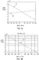
- FIG. 3A is a graph illustrating a simulated response curve for two sections of an AMR sensor.
- the x-axis represents magnetic field in units of Amperes per meter (A/m), and the y-axis represents the ratio between the output voltage (V output ) of the sensor and the supply voltage (V supply ) applied to the sensor.
- Curve 302 represents the response curve of a narrower constant width section of an AMR sensor, having a positive relative angle of conductive strips.
- Curve 304 represents the response curve of a greater constant width section of the AMR sensor, having a negative relative angle of conductive strips.
- curve 302 may represent the response of section 106b of AMR sensor 100
- curve 304 may represent the response of section 106a of AMR sensor 100.
- curve 302 may exhibit a negative slope
- curve 304 exhibits a positive slope. The magnitude of the slopes differs, however, with curve 304 exhibiting a smaller absolute slope.
- FIG. 3B illustrates the results of superimposing the curves 302 and 304 of FIG. 3A .
- the x-axis represents the magnetic field in units of A/m
- the y-axis represents Voutput/Vsupply, as with FIG. 3A .
- the positive-going curve 304 serves to remove some of the non-linear behavior of the AMR sensor, contributing to a linear overall response.
- a multi-section AMR sensor of the types described herein, for example as illustrated in FIG. 1 may exhibit a highly linear response in the presence of a magnetic field.
- the relative widths of the constant width sections may be selected to provide a desired degree of linear response.
- the inventor has recognized that it is desirable to generate two separate magnetic response regions with an AMR sensor, and to superimpose the magnetic responses of those regions to create a more linear overall response. To do this, it is desirable that the magnetic response of a first region of the AMR sensor exhibits its peak resistance change (DeltaR/R) over a smaller external magnetic field range than the second region of the AMR sensor, as shown in FIG. 3A .
- DeltaR/R peak resistance change
- the conductive strips 104 fully cover the transition regions 108a and 108b, which transition from the section 106a to 106b and from 106b to 106c, respectively.
- the transitions regions represents the transition between the wider constant width section and the narrower constant width section. Fully covering these transition regions with conductive strips ensures proper behavior of the AMR sensor.
- the resistive strip 102 and conductive strips 104 may be made of any suitable materials.
- the resistive strip 102 may be a magneto resistive material, for example formed of permalloy, which is a NiFe alloy. Other alloys may alternatively be used, such as alloys containing Ni, Fe, or Co (e.g., a CoFe alloy).
- the conductive strips 104 may be formed of Al, Au, Cu, or metal alloys, such as AlCu.
- FIG. 1 illustrates an AMR sensor having two ends of greater width than a middle section
- an AMR sensor has a single end of greater width than the remaining portion of the AMR sensor.
- an alternative embodiment may omit section 106c entirely.
- FIG. 4 illustrates this example.
- the AMR sensor 400 is the same as the AMR sensor 100 of FIG. 1 except that the section 106c is omitted.
- An aspect of the present application provides means for sensing a magnetic field.
- An aspect of the present application provides means for providing a linear response to magnetic field variation.
- the linear response may be a linear change in resistance, or a linear change in voltage.
- the linear response may be exhibited over a working range of the means.
- Some embodiments include means for providing a combined magnetic field response that is a superposition of a positive slope magnetic response and a negative slope magnetic response.
- a magnetic field sensor is provided, including electrical contacts, and means for providing a linear response to a magnetic field.
- the linear response may be a linear change in resistance, or a linear change in voltage.
- the electrical contacts may be positioned to allow for making electrical connection to ends of the magnetic field sensor.
- An aspect of the present application provides means for providing a linear change in resistance as a function of applied external magnetic field by superimposing a positive change in resistance as a function of the applied external magnetic field and a negative change in resistance as a function of the applied external magnetic field.
- An AMR sensor may include an input signal terminal, an output signal terminal, and the means, coupled between the input signal terminal and output signal terminal.
- the means may comprise means for providing a linear change in resistance as a function of applied external magnetic field by superimposing a positive change in resistance as a function of the applied external magnetic field and a negative change in resistance as a function of the applied external magnetic field, wherein a slope of the positive change in resistance as a function of applied external magnetic field has a different absolute value than a slope of the negative change in resistance as a function of applied external magnetic field.
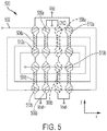
- FIG. 5 illustrates a magnetic field sensor according to a non-limiting embodiment of the present application.
- the magnetic field sensor 500 comprises a coil 502 and a grouping of eight AMR sensors 504a, 504b, 506a, 506b, 508a, 508b, 510a and 510b, of the types described previously herein.
- a supply voltage Vdd is applied to the grouping of AMR sensors at an input signal terminal, and a differential output signal is taken as Vout+ and Vout- from an output signal terminal.
- One end of the grouping of AMR sensors is grounded (GND), as shown.
- Vdd and GND in combination may represent an input signal terminal.
- the coil 502 may be used to magnetize the AMR sensors.
- the coil 502 overlies the AMR sensors in this non-limiting example, and may have any suitable structure.
- the illustrated shape is a non-limiting example.
- the coil 502 may be formed of any suitable conductive material.
- a metallic trace on a printed circuit board (PCB) may be used, although alternatives are possible.
- the coil 502 may be microfabricated.
- the magnetizing field created by the coil 502 may point either in the positive y-direction or the negative y-direction depending on where a particular AMR sensor is positioned relative to the coil. Assuming again the coil 502 overlies the AMR sensors, then when electric current conducts clockwise through the coil 502, the magnetic field experienced by AMR sensors 504a, 506a, 508a and 510a may point in the positive y-direction, while the magnetic field experienced by AMR sensors 504b, 506b, 508b, and 510b may point in the negative y-direction. This may be said to represent a situation in which the magnetizing field points outward, towards the ends or edges of the grouping of AMR sensors.
- the magnetic field experienced by AMR sensors 504a, 506a, 508a, and 510a may point in the negative y-direction, while the magnetic field experienced by AMR sensors 504b, 506b, 508b, and 510b may point in the positive y-direction.
- This may be said to represent a situation in which the magnetizing field points inward, toward a center of the grouping of AMR sensors. As described earlier, wider sections of an AMR sensor may magnetize more easily than narrower sections.
- the individual AMR sensors 504a, 504b, 506a, 506b, 508a, 508b, 510a, and 510b may magnetize from a wider region of the AMR sensor toward the center of the AMR sensor.
- the grouping of AMR sensors may be magnetized at various points during operation using the coil 502.
- AMR sensors 504a, 504b, 506a, 506b, 508a, 508b, 510a, and 510b may be of the types described previously herein.
- each may be an instance of the AMR sensor 100.
- the pairs of AMR sensors may exhibit opposing barber pole configurations, based on the angles of the conductive strips.
- the angle of the conductive strips 512a of AMR sensor 504a is opposite to that of the angle of the conductive strips 512b of AMR sensor 504b with respect to the x-direction.
- the angle of the conductive strips 512a at an end of the AMR sensor 504a is opposite to the angle of the conductive strips 512b at an end of the AMR sensor 504b, and the angle of the conductive strips 512a along a center segment of the AMR sensor 504a is opposite to the angle of the conductive strips 512b along a center segment of the AMR sensor 504b, relative to the x-direction.
- AMR sensors 506a and 506b exhibit opposing barber pole configurations relative to each other
- AMR sensors 508a and 508b exhibit opposing barber pole configurations relative to each other
- AMR sensors 510a and 510b exhibit opposing barber pole configurations relative to each other.
- the magnetic field sensor 500 may be magnetized using the coil 502.
- a supply voltage Vdd may then be applied as shown, and the differential output signal Vout+, Vout- may be monitored.
- the supply voltage Vdd may assume any suitable value.
- the group of AMR sensors of magnetic field sensor 500 may experience a change in resistance.
- the change in resistance may give rise to a change in the differential output signal Vout+, Vout-.
- the strength of the externally applied magnetic field may be determined from the change in the differential output signal Vout+, Vout-.
- magnetizing the AMR sensors by running a current through the coil 502 in a clockwise direction, and then subjecting the magnetic field sensor 500 to an external field in the x-direction will cause the resistances of AMR sensors 504a, 504b, 508a, and 508b to increase, and the resistances of AMRs senors 506a, 506b, 510a, and 510b to decrease.
- the resistances of AMR sensors 504a, 504b, 508a, and 508b increase in this example because of the angle between the current flow in those resistors and the x-direction external magnetic field.
- the current flow direction in the AMR sensors 506a, 506b, 510a, and 510b is different due to the opposite angle of the conductive strips of those AMR sensors, and thus the resistances of those AMR sensors decreases.
- an AMR sensor comprising the above-described means comprises multiple barber-pole AMR sensors.
- the means comprises multiple pairs of barber-pole AMR sensors having opposing barber pole configurations.
- Magnetic field sensors may be used in various settings to sense an external magnetic field.
- magnetic field sensors may be used on industrial equipment to sense magnetic fields experienced by the equipment.
- Magnetic field sensors may be used on medical equipment, or in structural monitoring (such as monitoring of buildings or sensors on buildings).
- Magnetic field sensors may be used as compasses.
- Magnetic field sensors may be used as current sensors. Other uses are also possible.
- an aspect of the present application provides a magnetic field sensor comprising two or more pairs of AMR sensors, where the AMR sensors within the pairs exhibit opposing barber pole configurations to each other.
- Each of the AMR sensors may have a section of wider, constant width and a section of narrower, constant width.
- the ends of each AMR sensor have a wider, constant width than a central section of the AMR sensor.
- Magnetic field sensors of different constructions than that of FIG. 5 are possible.
- a magnetic field sensor may differ from magnetic field sensor 500 by omitting AMR sensors 504b, 506b, 508b, and 510b.
- a magnetic field sensor may differ from magnetic field sensor in including just AMR sensors 504a, 504b, 506a, and 506b.
- Such a configuration may be considered a half-bridge magnetic field sensor.
- such a half-bridge magnetic field sensor may be magnetized in only a single direction by a magnetizing coil.
- one or more of the AMR sensors of FIG. 5 may in practice be implemented as multiple barber pole AMR sensors connected in series.
- an AMR sensors exhibiting enhanced linearity is provided.
- the AMR sensor may exhibit substantial linearity in its magnetic field response over a working range of magnetic fields.
- the working range may encompass a range of magnetic fields up to 10,000 A/m, up to 5,000 A/m, or up to 2,000 A/m, although other ranges are possible.
- an AMR sensor is provided exhibiting enhanced ease of magnetization.
- the AMR sensor may have opposing ends of greater, constant width than a center section of the AMR sensor.
- the terms “approximately”, “substantially,” and “about” may be used to mean within ⁇ 20% of a target value in some embodiments, within ⁇ 10% of a target value in some embodiments, within ⁇ 5% of a target value in some embodiments, and yet within ⁇ 2% of a target value in some embodiments.
- the terms “approximately” and “about” may include the target value.
Landscapes
- Physics & Mathematics (AREA)
- Condensed Matter Physics & Semiconductors (AREA)
- General Physics & Mathematics (AREA)
- Measuring Magnetic Variables (AREA)
- Hall/Mr Elements (AREA)
Abstract
Description
- The present application relates to magnetic field sensors.
- Anisotropic-magnetoresistive (AMR) sensors are used to sense magnetic fields by detecting a change in resistance of the sensor as a result of the magnetic field. Some AMR sensors have a so-called "barber pole" structure, with a resistive strip that has conductive strips arranged thereon in a pattern resembling a barber pole.
- Anisotropic-magnetoresistive (AMR) sensors are described. The AMR sensors have a barber pole structure with multiple constant width sections of different width. In some embodiments, two sections of greater, constant width are positioned at ends of the AMR sensor, with a section of smaller width positioned in between. The sections of greater width may have a total length less than the section of smaller width. The structures described may provide enhanced linearity.
- According to some embodiments, an anisotropic-magnetoresistive (AMR) sensor with improved linearity is provided, comprising: a strip of magneto resistive material, the strip comprising a first section having a first constant width and a second section having a second constant width greater than the first constant width; a first plurality of conductive strips arranged on the first section and oriented at a first angle relative to the strip of magneto resistive material; and a second plurality of conductive strips arranged on the second section and oriented at a second angle relative to the strip of magneto resistive material.
- According to some embodiments, an anisotropic-magnetoresistive (AMR) sensor with improved linearity is provided, comprising: a continuous strip of magneto resistive material having first and second barber pole portions, the first barber pole portion having a first width and a first conductive strip angle and the second barber pole portion having a second width different than the first width and a second conductive strip angle different than the first conductive strip angle.
- According to some embodiments, an anisotropic-magnetoresistive (AMR) sensor with improved linearity is provided, comprising an input signal terminal; an output signal terminal; and coupled between the input signal terminal and output signal terminal, means for providing a linear change in resistance as a function of applied external magnetic field by superimposing a positive change in resistance as a function of the applied external magnetic field and a negative change in resistance as a function of the applied external magnetic field.
- Various aspects and embodiments of the application will be described with reference to the following figures. It should be appreciated that the figures are not necessarily drawn to scale. Items appearing in multiple figures are indicated by the same reference number in all the figures in which they appear.
-
FIG. 1 illustrates an anisotropic-magnetoresistive (AMR) sensor according to a non-limiting embodiment of the present application, having multiple sections of different constant width. -
FIG. 2 illustrates the resistive strip ofFIG. 1 . -
FIG. 3A is a graph illustrating the response of two separate constant width portions of an AMR sensor of the types described herein. -
FIG. 3B is a graph illustrating the overall response of the AMR sensor illustrated inFIG. 4A . -
FIG. 4 illustrates an AMR sensor according to a non-limiting embodiment of the present application, having multiple sections of different constant widths. -
FIG. 5 illustrates a magnetic field sensor according to a non-limiting embodiment of the present application. - According to an aspect of the present application, an anisotropic-magnetoresistive (AMR) sensor is provided exhibiting a high degree of linearity. The linearity refers to the changes in resistance as a function of magnetization. The AMR sensor may include a resistive strip with different constant width sections. Conductive strips on the resistive strip may be positioned at different angles relative to each other depending on which constant width section they overlie. In some embodiments, the conductive strips on a wider section of the resistive strip may be at an opposite angle relative to the conductive strips on a narrower section of the resistive strip.
-
FIG. 1 illustrates an anisotropic-magnetoresistive (AMR) sensor according to a non-limiting embodiment of the present application, having multiple segments or sections of different constant width. TheAMR sensor 100 comprises aresistive strip 102 and a plurality ofconductive strips 104. TheAMR sensor 100 exhibits afirst section 106a,second section 106b, andthird section 106c. - As shown in
FIG. 2 , theresistive strip 102 is a continuous strip having different widths, shown here as W1, W2, and W3. Specifically,section 106a has a width W1,section 106b has a width W2, andsection 106c has a width W3. The width is oriented along the y-axis in this example. Referring back toFIG. 1 , the resistive sections ofsection 106a have a combined length L1 representing the sum of the lengths L1a , L1b , L1c , and L1d , which are the portions of theresistive strip 102 between theconductive strips 104 in thesection 106a. The resistive sections ofsection 106b have a combined length L2, representing the sum of the lengths L2a ... L2n , which are the portions of theresistive strip 102 between theconductive strips 104 in thesection 106b. The resistive sections ofsection 106c have a combined length L3, representing the sum of the lengths L3a , L3b , L3c , and L3d, which are the portions of theresistive strip 102 between theconductive strips 104 in thesection 106c. - The widths W1, W2, and W3 are constant widths over the respective length of that section. That is, W1 is constant over the length L1, W2 is constant over the length L2, and W3 is constant over the length L3. The widths W1 and W3 are greater than W2. In some embodiments, W1 and W3 are equal. W1 and W3 may be greater than W2 by a factor between 1.1 and 2.5. That is, the ratio of the width of the W1 (and likewise W3 ) to the width W2 may be between 1.1 and 2.5, including any value within that range. Stated another way, W1 (and likewise W3 ) may be between 10% greater than W1 and 150% greater than W1 . Both W1 and W2 may be in the range of 1 micron to 20 microns in some embodiments. Having W1 and W3 larger than W2 can facilitate magnetizing the
AMR sensor 100. Typically a magnetizing field is applied at one on more ends of an AMR sensor. Sections of greater width are easier to magnetize. Magnetization can travel along the length of the sensor. Therefore, making the ends easier to magnetize by making them wider may facilitate the magnetization process. - The fact that widths W1, W2, and W3 are constant means that the current through the resistive strip portions of the
sections FIG. 2 , the current through those sections will move in the x-direction. Having the current moving in the same direction throughsections AMR sensor 100. - The lengths L1, L2, and L3 may assume any suitable values for providing desired magnetization, as described further below. In some embodiments, L1 and L3 may be equal, though not all embodiments are limited in this respect. In some embodiments, the total length of L1 plus L3 may be less than L2. For example, the ratio of L2 over (L1 + L3) may be between 1.2 and 40, including any value within that range. The total length of a resistive strip, such as
resistive strip 102, may be in the range of 50µm up to 1000µm long, in some non-limiting embodiments. -
FIG. 2 also illustrates how theresistive strip 102 has atapered end 120. In fact, in the illustrated example, theresistive strip 102 has a tapered endadjacent section 106a and a tapered endadjacent section 106c. The tapered ends may facilitate the magnetization stability of the resistive strip. - Returning to
FIG. 1 , it can be seen that theconductive strips 104 are oriented at different angles depending on which section they are a part of. That is, the conductive strips ofsection 106a are oriented at one angle, and the conductive strips ofsection 106b at another. In the non-limiting example illustrated, the conductive strips ofsection 106a are oriented at an opposite angle to those ofsection 106b, relative to a line in-plane with and perpendicular to theresistive strip 102. Thus, for purposes of illustration, the conductive strips ofsection 106b may be said to be oriented at an angle θ, while the conductive strips ofsection 106a may be said to be oriented at - θ. The value of θ may be any suitable value to provide a desired level of linearization of the magnetic response of the AMR sensor. As a non-limiting example, θ may assume any value in a range from 30 degrees to 60 degrees. - It should be appreciated from
FIG. 1 that theAMR sensor 100 comprises multiple barber pole portions.Section 106a may represent a first barber pole portion,section 106b a second barber pole portion, andsection 106c a third barber pole portion. The barber pole portions may represent portions of the continuous AMR sensor that differ in some way in their width and/or conductive strip configuration from a neighboring portion. - The
AMR sensor 100 may exhibit enhanced linearity compared to conventional AMR sensors. The magnetic response of a barber pole AMR sensor depends on both the width of the sensor and the angle of the conductive strips. For an AMR sensor with a constant width and a single conductive strip angle, the response is typically non-linear. Flipping the angle of the conductive strips from a positive angle to a negative angle (or vice versa) changes the slope of the response curve from positive to negative (or vice versa). The inventor has appreciated that having a multi-section AMR sensor where one section has a positive slope response and another section has a negative slope response may facilitate achieving a more linear response curve.FIGs. 3A and 3B illustrate a non-limiting example. -
FIG. 3A is a graph illustrating a simulated response curve for two sections of an AMR sensor. The x-axis represents magnetic field in units of Amperes per meter (A/m), and the y-axis represents the ratio between the output voltage (Voutput) of the sensor and the supply voltage (Vsupply) applied to the sensor.Curve 302 represents the response curve of a narrower constant width section of an AMR sensor, having a positive relative angle of conductive strips.Curve 304 represents the response curve of a greater constant width section of the AMR sensor, having a negative relative angle of conductive strips. For example,curve 302 may represent the response ofsection 106b ofAMR sensor 100, whilecurve 304 may represent the response ofsection 106a ofAMR sensor 100. As can be seen inFIG. 3A ,curve 302 may exhibit a negative slope, whilecurve 304 exhibits a positive slope. The magnitude of the slopes differs, however, withcurve 304 exhibiting a smaller absolute slope. -
FIG. 3B illustrates the results of superimposing thecurves FIG. 3A . The x-axis represents the magnetic field in units of A/m, and the y-axis represents Voutput/Vsupply, as withFIG. 3A . As shown, the curve 306-representing the combination ofcurves 302 and 304-exhibits a highly linear response. The positive-goingcurve 304 serves to remove some of the non-linear behavior of the AMR sensor, contributing to a linear overall response. - It should be appreciated from
FIGs. 3A and 3B that a multi-section AMR sensor of the types described herein, for example as illustrated inFIG. 1 , may exhibit a highly linear response in the presence of a magnetic field. The relative widths of the constant width sections may be selected to provide a desired degree of linear response. - Moreover, it should be appreciated that according to an aspect of the present application, the inventor has recognized that it is desirable to generate two separate magnetic response regions with an AMR sensor, and to superimpose the magnetic responses of those regions to create a more linear overall response. To do this, it is desirable that the magnetic response of a first region of the AMR sensor exhibits its peak resistance change (DeltaR/R) over a smaller external magnetic field range than the second region of the AMR sensor, as shown in
FIG. 3A . - Returning to
FIG. 1 , theconductive strips 104 fully cover thetransition regions section 106a to 106b and from 106b to 106c, respectively. The transitions regions represents the transition between the wider constant width section and the narrower constant width section. Fully covering these transition regions with conductive strips ensures proper behavior of the AMR sensor. - The
resistive strip 102 andconductive strips 104 may be made of any suitable materials. Theresistive strip 102 may be a magneto resistive material, for example formed of permalloy, which is a NiFe alloy. Other alloys may alternatively be used, such as alloys containing Ni, Fe, or Co (e.g., a CoFe alloy). Theconductive strips 104 may be formed of Al, Au, Cu, or metal alloys, such as AlCu. - While
FIG. 1 illustrates an AMR sensor having two ends of greater width than a middle section, alternatives are possible. For example, according to one alternative an AMR sensor has a single end of greater width than the remaining portion of the AMR sensor. For example, referring toFIG. 1 , an alternative embodiment may omitsection 106c entirely.FIG. 4 illustrates this example. TheAMR sensor 400 is the same as theAMR sensor 100 ofFIG. 1 except that thesection 106c is omitted. - An aspect of the present application provides means for sensing a magnetic field. An aspect of the present application provides means for providing a linear response to magnetic field variation. The linear response may be a linear change in resistance, or a linear change in voltage. The linear response may be exhibited over a working range of the means. Some embodiments include means for providing a combined magnetic field response that is a superposition of a positive slope magnetic response and a negative slope magnetic response. In some embodiments, a magnetic field sensor is provided, including electrical contacts, and means for providing a linear response to a magnetic field. The linear response may be a linear change in resistance, or a linear change in voltage. The electrical contacts may be positioned to allow for making electrical connection to ends of the magnetic field sensor.
- An aspect of the present application provides means for providing a linear change in resistance as a function of applied external magnetic field by superimposing a positive change in resistance as a function of the applied external magnetic field and a negative change in resistance as a function of the applied external magnetic field. An AMR sensor may include an input signal terminal, an output signal terminal, and the means, coupled between the input signal terminal and output signal terminal. The means may comprise means for providing a linear change in resistance as a function of applied external magnetic field by superimposing a positive change in resistance as a function of the applied external magnetic field and a negative change in resistance as a function of the applied external magnetic field, wherein a slope of the positive change in resistance as a function of applied external magnetic field has a different absolute value than a slope of the negative change in resistance as a function of applied external magnetic field.
-
FIG. 5 illustrates a magnetic field sensor according to a non-limiting embodiment of the present application. Themagnetic field sensor 500 comprises acoil 502 and a grouping of eightAMR sensors - The
coil 502 may be used to magnetize the AMR sensors. Thecoil 502 overlies the AMR sensors in this non-limiting example, and may have any suitable structure. The illustrated shape is a non-limiting example. Thecoil 502 may be formed of any suitable conductive material. For example, a metallic trace on a printed circuit board (PCB) may be used, although alternatives are possible. In some embodiments, thecoil 502 may be microfabricated. - The magnetizing field created by the
coil 502 may point either in the positive y-direction or the negative y-direction depending on where a particular AMR sensor is positioned relative to the coil. Assuming again thecoil 502 overlies the AMR sensors, then when electric current conducts clockwise through thecoil 502, the magnetic field experienced byAMR sensors AMR sensors coil 502, the magnetic field experienced byAMR sensors AMR sensors magnetic field sensor 500 theindividual AMR sensors coil 502. -
AMR sensors AMR sensor 100. As shown, the pairs of AMR sensors may exhibit opposing barber pole configurations, based on the angles of the conductive strips. For example, it can be seen that the angle of theconductive strips 512a ofAMR sensor 504a is opposite to that of the angle of theconductive strips 512b ofAMR sensor 504b with respect to the x-direction. More specifically, the angle of theconductive strips 512a at an end of theAMR sensor 504a is opposite to the angle of theconductive strips 512b at an end of theAMR sensor 504b, and the angle of theconductive strips 512a along a center segment of theAMR sensor 504a is opposite to the angle of theconductive strips 512b along a center segment of theAMR sensor 504b, relative to the x-direction. Likewise,AMR sensors AMR sensors AMR sensors - In operation, the
magnetic field sensor 500 may be magnetized using thecoil 502. A supply voltage Vdd may then be applied as shown, and the differential output signal Vout+, Vout- may be monitored. The supply voltage Vdd may assume any suitable value. When themagnetic field sensor 500 is exposed to an externally applied magnetic field, the group of AMR sensors ofmagnetic field sensor 500 may experience a change in resistance. The change in resistance may give rise to a change in the differential output signal Vout+, Vout-. The strength of the externally applied magnetic field may be determined from the change in the differential output signal Vout+, Vout-. As a non-limiting example, magnetizing the AMR sensors by running a current through thecoil 502 in a clockwise direction, and then subjecting themagnetic field sensor 500 to an external field in the x-direction will cause the resistances ofAMR sensors AMR sensors AMR sensors - As has been described previously, aspects of the present application provide means for providing a linear change in resistance as a function of applied external magnetic field by superimposing a positive change in resistance as a function of the applied external magnetic field and a negative change in resistance as a function of the applied external magnetic field. It should be appreciated from
FIG. 5 that in some embodiments according to such aspects, an AMR sensor comprising the above-described means comprises multiple barber-pole AMR sensors. In some embodiments, the means comprises multiple pairs of barber-pole AMR sensors having opposing barber pole configurations. - Magnetic field sensors according to aspects of the present application, such as
magnetic field sensor 500, may be used in various settings to sense an external magnetic field. For example, magnetic field sensors may be used on industrial equipment to sense magnetic fields experienced by the equipment. Magnetic field sensors may be used on medical equipment, or in structural monitoring (such as monitoring of buildings or sensors on buildings). Magnetic field sensors may be used as compasses. Magnetic field sensors may be used as current sensors. Other uses are also possible. - It should be appreciated from
FIG. 5 that an aspect of the present application provides a magnetic field sensor comprising two or more pairs of AMR sensors, where the AMR sensors within the pairs exhibit opposing barber pole configurations to each other. Each of the AMR sensors may have a section of wider, constant width and a section of narrower, constant width. In some embodiments, the ends of each AMR sensor have a wider, constant width than a central section of the AMR sensor. - Magnetic field sensors of different constructions than that of
FIG. 5 are possible. For example, a magnetic field sensor may differ frommagnetic field sensor 500 by omittingAMR sensors AMR sensors FIG. 5 may in practice be implemented as multiple barber pole AMR sensors connected in series. - Aspects of the present application may provide various benefits, some of which have been described. It should be appreciated that not every embodiment necessarily provides all benefits, and that benefits other than those listed may be provided. According to an aspect of the present application, an AMR sensors exhibiting enhanced linearity is provided. The AMR sensor may exhibit substantial linearity in its magnetic field response over a working range of magnetic fields. In some embodiments, the working range may encompass a range of magnetic fields up to 10,000 A/m, up to 5,000 A/m, or up to 2,000 A/m, although other ranges are possible. According to aspects of the present application, an AMR sensor is provided exhibiting enhanced ease of magnetization. The AMR sensor may have opposing ends of greater, constant width than a center section of the AMR sensor.
- The terms "approximately", "substantially," and "about" may be used to mean within ±20% of a target value in some embodiments, within ±10% of a target value in some embodiments, within ±5% of a target value in some embodiments, and yet within ±2% of a target value in some embodiments. The terms "approximately" and "about" may include the target value.
Claims (15)
- An anisotropic-magnetoresistive (AMR) sensor with improved linearity, comprising:a strip of magneto resistive material, the strip comprising a first section having a first constant width and a second section having a second constant width greater than the first constant width;a first plurality of conductive strips arranged on the first section and oriented at a first angle relative to the strip of magneto resistive material; anda second plurality of conductive strips arranged on the second section and oriented at a second angle relative to the strip of magneto resistive material.
- The AMR sensor of claim 1, wherein the first angle is opposite the second angle with respect to a line in-plane with the strip of magneto resistive material and perpendicular with the strip of magneto resistive material.
- The AMR sensor of claims 1 or 2, wherein the strip of magneto resistive material further comprises a third section having a third constant width greater than the first constant width and a third plurality of conductive strips oriented at a third angle relative to the strip of magneto resistive material.
- The AMR sensor of claim 3, wherein the second constant width and third constant width are substantially the same, and wherein the second angle and the third angle are substantially the same; and/or the first section is between the second and third sections.
- The AMR sensor of claims 3 or 4, wherein a combined length of resistive portions of the first section is between 1.2 and 40 times greater than a combined length of resistive portions of the second section and third section.
- The AMR sensor of any preceding claim, wherein the strip of magneto resistive material further comprises a third section of varying width connecting the first section and second section, and wherein the AMR sensor further comprises a conductive material covering the third section.
- The AMR sensor of any preceding claim, further comprising a tapered end adjacent the second section.
- An anisotropic-magnetoresistive (AMR) sensor with improved linearity, comprising:
a continuous strip of magneto resistive material having first and second barber pole portions, the first barber pole portion having a first width and a first conductive strip angle and the second barber pole portion having a second width different than the first width and a second conductive strip angle different than the first conductive strip angle. - The AMR sensor of claim 8, wherein the first angle is opposite the second angle with respect to a line in-plane with the strip of magneto resistive material and perpendicular with the strip of magneto resistive material; and/or
the AMR sensor further comprises a third barber pole portion having a third constant width greater than the first constant width and a third conductive strip angle different than the first conductive strip angle. - The AMR sensor of claim 9, wherein one or more of the following applies:the second constant width and third constant width are substantially the same, and wherein the second angle and the third angle are substantially the same;the first barber pole portion is between the second and third barber pole portions; anda combined length of resistive portions of the first barber pole portion is between 1.2 and 40 times greater than a combined length of resistive portions of the second barber pole portion and third barber pole portion.
- The AMR sensor of any of claims 8 to 10, wherein the strip of magneto resistive material further comprises a section of varying width connecting the first barber pole portion and second barber pole portion, and wherein the AMR sensor further comprises a conductive material covering the section of varying width.
- The AMR sensor of any of claims 8 to 11, further comprising a tapered end adjacent the second barber pole portion.
- An anisotropic-magnetoresistive (AMR) sensor with improved linearity, comprising
an input signal terminal;
an output signal terminal; and
coupled between the input signal terminal and output signal terminal, means for providing a linear change in resistance as a function of applied external magnetic field by superimposing a positive change in resistance as a function of the applied external magnetic field and a negative change in resistance as a function of the applied external magnetic field. - The AMR sensor of claim 13, wherein the means comprises means for providing a linear change in resistance as a function of applied external magnetic field by superimposing a positive change in resistance as a function of the applied external magnetic field and a negative change in resistance as a function of the applied external magnetic field, wherein a slope of the positive change in resistance as a function of applied external magnetic field has a different absolute value than a slope of the negative change in resistance as a function of applied external magnetic field.
- The AMR sensor of claim 14, wherein the means comprises multiple barber-pole AMR sensors; or multiple pairs of barber-pole AMR sensors having opposing barber pole configurations.
Applications Claiming Priority (1)
| Application Number | Priority Date | Filing Date | Title |
|---|---|---|---|
| US16/837,614 US11719772B2 (en) | 2020-04-01 | 2020-04-01 | AMR (XMR) sensor with increased linear range |
Publications (2)
| Publication Number | Publication Date |
|---|---|
| EP3889629A1 true EP3889629A1 (en) | 2021-10-06 |
| EP3889629B1 EP3889629B1 (en) | 2024-03-20 |
Family
ID=75277826
Family Applications (1)
| Application Number | Title | Priority Date | Filing Date |
|---|---|---|---|
| EP21165525.3A Active EP3889629B1 (en) | 2020-04-01 | 2021-03-29 | Amr (xmr) sensor with increased linear range |
Country Status (4)
| Country | Link |
|---|---|
| US (1) | US11719772B2 (en) |
| EP (1) | EP3889629B1 (en) |
| JP (1) | JP7725219B2 (en) |
| CN (1) | CN113495234B (en) |
Families Citing this family (2)
| Publication number | Priority date | Publication date | Assignee | Title |
|---|---|---|---|---|
| US12078695B2 (en) | 2021-04-12 | 2024-09-03 | Analog Devices International Unlimited Company | Magnetic field sensor with overcurrent detection |
| US12146928B2 (en) | 2021-04-12 | 2024-11-19 | Analog Devices International Unlimited Company | Magnetic field sensor with overcurrent detection |
Citations (2)
| Publication number | Priority date | Publication date | Assignee | Title |
|---|---|---|---|---|
| DE4335826A1 (en) * | 1993-10-20 | 1995-04-27 | Siemens Ag | Measuring instrument with magnetoresistive sensor devices in a bridge circuit |
| EP2671091B1 (en) * | 2011-02-03 | 2014-12-24 | Sensitec GmbH | Magnetic field sensing device |
Family Cites Families (43)
| Publication number | Priority date | Publication date | Assignee | Title |
|---|---|---|---|---|
| DE260773C (en) | ||||
| NL7901578A (en) | 1979-02-28 | 1980-09-01 | Philips Nv | MAGNETIC RESISTANCE HEAD. |
| DE3507665A1 (en) | 1985-03-05 | 1986-09-11 | VEB Meßtechnik Mellenbach Betrieb des Kombinates VEB Elektro-Apparate-Werke Berlin-Treptow "Friedrich Ebert", DDR 6428 Mellenbach-Glasbach | Sensor for detecting local magnetic fields |
| JPH02229479A (en) * | 1989-03-02 | 1990-09-12 | Fujitsu Ltd | Magnetoresistance element |
| US5301079A (en) * | 1992-11-17 | 1994-04-05 | International Business Machines Corporation | Current biased magnetoresistive spin valve sensor |
| DE4314539C2 (en) | 1993-05-03 | 1998-11-05 | Siemens Ag | Magnetic resistance sensor with vertical sensitivity and use of the sensor |
| US5452163A (en) | 1993-12-23 | 1995-09-19 | International Business Machines Corporation | Multilayer magnetoresistive sensor |
| JP4299901B2 (en) * | 1997-12-04 | 2009-07-22 | ソニーマニュファクチュアリングシステムズ株式会社 | Position detection device |
| US6222361B1 (en) * | 1997-12-04 | 2001-04-24 | Sony Precision Technology Inc. | Position detecting device using varying width magneto-resistive effect sensor |
| CN100403048C (en) | 2000-10-26 | 2008-07-16 | 财团法人电气磁气材料研究所 | thin film magnetic sensor |
| JP2003031867A (en) | 2001-07-17 | 2003-01-31 | Hitachi Ltd | Magnetoresistive element with stacked oxide magnetic layer and metal magnetic film |
| US6850057B2 (en) * | 2001-07-19 | 2005-02-01 | Honeywell International, Inc. | Barber pole structure for magnetoresistive sensors and method of forming same |
| JP4229257B2 (en) | 2001-11-02 | 2009-02-25 | Tdk株式会社 | Thin film device and method of manufacturing thin film magnetic head assembly |
| DE10308030B4 (en) | 2003-02-24 | 2011-02-03 | Meas Deutschland Gmbh | Magnetoresistive sensor for determining an angle or position |
| DE10342260B4 (en) | 2003-09-11 | 2014-11-20 | Meas Deutschland Gmbh | Magnetoresistive sensor in the form of a half or full bridge circuit |
| TWI278650B (en) | 2004-09-28 | 2007-04-11 | Yamaha Corp | Magnetic sensor using giant magnetoresistive elements and method for manufacturing the same |
| TWI361503B (en) | 2005-03-17 | 2012-04-01 | Yamaha Corp | Three-axis magnetic sensor and manufacturing method therefor |
| WO2008120118A2 (en) | 2007-03-30 | 2008-10-09 | Nxp B.V. | Magneto-resistive sensor |
| DE102007023815A1 (en) | 2007-05-21 | 2008-11-27 | Sensitec Gmbh | Arrangement for scanning a linear or circular scale of ferromagnetic material |
| DE102007062633B4 (en) | 2007-12-22 | 2010-04-15 | Sensitec Gmbh | Arrangement for potential-free measurement of currents |
| EP2219033B1 (en) | 2008-12-30 | 2016-05-25 | MicroCoat Biotechnologie GmbH | Device, instrument and process for detecting magnetically labeled analytes |
| IT1403433B1 (en) | 2010-12-27 | 2013-10-17 | St Microelectronics Srl | MAGNETORESISTIVE SENSOR WITH REDUCED PARASITE CAPACITY, AND METHOD |
| DE102012206404B4 (en) | 2011-08-29 | 2014-01-02 | Liba Maschinenfabrik Gmbh | Multiaxial fabric scrim, method of making a multiaxial scrim, multi-axial, and unidirectional filament and multi-axial threadline fabrication facilities |
| TWI409488B (en) | 2011-09-29 | 2013-09-21 | Voltafield Technology Corp | Magnatoresistive sensing component and magnatoresistive sensing device |
| US8947082B2 (en) * | 2011-10-21 | 2015-02-03 | University College Cork, National University Of Ireland | Dual-axis anisotropic magnetoresistive sensors |
| DE102012208404A1 (en) * | 2012-05-21 | 2013-11-21 | Robert Bosch Gmbh | Differential magnetic field sensor arrangement |
| JP5911065B2 (en) | 2012-06-12 | 2016-04-27 | 公立大学法人大阪市立大学 | Earth leakage detector |
| DE102012012759A1 (en) | 2012-06-27 | 2014-01-02 | Sensitec Gmbh | Arrangement for current measurement |
| DE102013104486A1 (en) * | 2013-05-02 | 2014-11-20 | Sensitec Gmbh | Magnetic field sensor device |
| DE102013107821A1 (en) | 2013-07-22 | 2015-01-22 | Sensitec Gmbh | Multi-component magnetic field sensor |
| US9618589B2 (en) | 2013-10-18 | 2017-04-11 | Infineon Technologies Ag | First and second magneto-resistive sensors formed by first and second sections of a layer stack |
| JP6233863B2 (en) | 2014-03-28 | 2017-11-22 | アルプス電気株式会社 | Magnetic sensor, magnetic sensor manufacturing method, and current sensor |
| CN106463612A (en) | 2014-05-30 | 2017-02-22 | 株式会社村田制作所 | Magnetoresistive element, magnetic sensor and current sensor |
| US10317480B2 (en) | 2014-10-15 | 2019-06-11 | Infineon Technologies Ag | Magneto resistive device |
| US9632150B2 (en) * | 2015-04-27 | 2017-04-25 | Everspin Technologies, Inc. | Magnetic field sensor with increased field range |
| CN106291414B (en) * | 2015-06-26 | 2019-12-20 | 意法半导体股份有限公司 | Large-scale integrated AMR magnetic resistor |
| US20170115363A1 (en) | 2015-10-26 | 2017-04-27 | Memsic Semiconductor (Wuxi) Co., Ltd. | Magnetic Field Sensor With Three-Dimensional Spiral Reset Coil |
| US10114085B2 (en) * | 2016-03-04 | 2018-10-30 | Allegro Microsystems, Llc | Magnetic field sensor with improved response immunity |
| US11187763B2 (en) | 2016-03-23 | 2021-11-30 | Analog Devices International Unlimited Company | Offset compensation for magnetic field detector |
| JP6569824B2 (en) * | 2016-12-19 | 2019-09-04 | 株式会社村田製作所 | Magnetoresistive element and magnetic sensor |
| EP3410075B1 (en) | 2017-05-30 | 2020-10-07 | MEAS France | Temperature compensation for magnetic field sensing devices and a magnetic field sensing device using the same |
| US10782154B2 (en) * | 2017-06-26 | 2020-09-22 | Texas Instruments Incorporated | Tilted segmented anisotropic magneto-resistive angular sensor |
| CN108267632A (en) * | 2018-04-13 | 2018-07-10 | 贵州雅光电子科技股份有限公司 | A kind of AMR linear transducers and its design method based on winding bias |
-
2020
- 2020-04-01 US US16/837,614 patent/US11719772B2/en active Active
-
2021
- 2021-03-29 EP EP21165525.3A patent/EP3889629B1/en active Active
- 2021-03-31 JP JP2021060632A patent/JP7725219B2/en active Active
- 2021-04-01 CN CN202110353393.4A patent/CN113495234B/en active Active
Patent Citations (2)
| Publication number | Priority date | Publication date | Assignee | Title |
|---|---|---|---|---|
| DE4335826A1 (en) * | 1993-10-20 | 1995-04-27 | Siemens Ag | Measuring instrument with magnetoresistive sensor devices in a bridge circuit |
| EP2671091B1 (en) * | 2011-02-03 | 2014-12-24 | Sensitec GmbH | Magnetic field sensing device |
Also Published As
| Publication number | Publication date |
|---|---|
| JP2021162600A (en) | 2021-10-11 |
| US20210311141A1 (en) | 2021-10-07 |
| EP3889629B1 (en) | 2024-03-20 |
| US11719772B2 (en) | 2023-08-08 |
| CN113495234B (en) | 2024-06-04 |
| CN113495234A (en) | 2021-10-12 |
| JP7725219B2 (en) | 2025-08-19 |
Similar Documents
| Publication | Publication Date | Title |
|---|---|---|
| JP3465059B2 (en) | Magnetic field sensor comprising magnetization reversal conductor and one or more magnetoresistive resistors | |
| DE69426599T2 (en) | MAGNETORESISTIVE PROXIMITY SENSOR | |
| CN106291414B (en) | Large-scale integrated AMR magnetic resistor | |
| US4361805A (en) | Magnetoresistive displacement sensor arrangement | |
| EP2992342B1 (en) | Magnetic field sensor device | |
| US9678177B2 (en) | Magnetic sensor device for suppressing magnetic saturation | |
| KR960705187A (en) | Magnetoresistive linear displacement sensor, angular displacement sensor and variable resistance | |
| EP3889629B1 (en) | Amr (xmr) sensor with increased linear range | |
| US20180372812A1 (en) | Equilibrium-type magnetic field detection device | |
| JP2008216230A (en) | Current sensor | |
| DE102011104009A1 (en) | Magnetic position detection device | |
| JP2021092526A (en) | Magnetic field detector and current detector | |
| DE10011176C2 (en) | Two-dimensional position sensor with magnetic resistance | |
| DE102021127855A1 (en) | Current sensor comprising a magnetic field sensor in a V-shaped arrangement | |
| DE10051160A1 (en) | Sensor arrangement for contactless measurement of low currents positioned in loop formed by symmetrical conductor branches | |
| DE102014219009A1 (en) | position sensor | |
| EP0730162A2 (en) | Sensor apparatus with magnetoresistif sensorelement in a bridge circuit | |
| DD155220A1 (en) | MAGNETORESISTIVE FIELD EFFECT BUILDING ELEMENT | |
| DE4314539C2 (en) | Magnetic resistance sensor with vertical sensitivity and use of the sensor | |
| CN108363025B (en) | magnetic field sensor | |
| DE4426367A1 (en) | Position sensor | |
| US20260098918A1 (en) | Spin hall magnetic sensor | |
| DE102007040183A1 (en) | Magnetic field sensor, for external and especially terrestrial magnetic fields, has parallel magnetized strip layers with contacts for current/voltage for measurement signals from their output difference | |
| RU2857494C1 (en) | Magnetoresistor | |
| EP0307729A1 (en) | Test arrangement for electronic circuits |
Legal Events
| Date | Code | Title | Description |
|---|---|---|---|
| PUAI | Public reference made under article 153(3) epc to a published international application that has entered the european phase |
Free format text: ORIGINAL CODE: 0009012 |
|
| STAA | Information on the status of an ep patent application or granted ep patent |
Free format text: STATUS: THE APPLICATION HAS BEEN PUBLISHED |
|
| AK | Designated contracting states |
Kind code of ref document: A1 Designated state(s): AL AT BE BG CH CY CZ DE DK EE ES FI FR GB GR HR HU IE IS IT LI LT LU LV MC MK MT NL NO PL PT RO RS SE SI SK SM TR |
|
| STAA | Information on the status of an ep patent application or granted ep patent |
Free format text: STATUS: REQUEST FOR EXAMINATION WAS MADE |
|
| 17P | Request for examination filed |
Effective date: 20220201 |
|
| RBV | Designated contracting states (corrected) |
Designated state(s): AL AT BE BG CH CY CZ DE DK EE ES FI FR GB GR HR HU IE IS IT LI LT LU LV MC MK MT NL NO PL PT RO RS SE SI SK SM TR |
|
| GRAP | Despatch of communication of intention to grant a patent |
Free format text: ORIGINAL CODE: EPIDOSNIGR1 |
|
| STAA | Information on the status of an ep patent application or granted ep patent |
Free format text: STATUS: GRANT OF PATENT IS INTENDED |
|
| RIC1 | Information provided on ipc code assigned before grant |
Ipc: G01R 33/09 20060101AFI20230530BHEP |
|
| INTG | Intention to grant announced |
Effective date: 20230615 |
|
| GRAJ | Information related to disapproval of communication of intention to grant by the applicant or resumption of examination proceedings by the epo deleted |
Free format text: ORIGINAL CODE: EPIDOSDIGR1 |
|
| STAA | Information on the status of an ep patent application or granted ep patent |
Free format text: STATUS: REQUEST FOR EXAMINATION WAS MADE |
|
| INTC | Intention to grant announced (deleted) | ||
| GRAP | Despatch of communication of intention to grant a patent |
Free format text: ORIGINAL CODE: EPIDOSNIGR1 |
|
| STAA | Information on the status of an ep patent application or granted ep patent |
Free format text: STATUS: GRANT OF PATENT IS INTENDED |
|
| INTG | Intention to grant announced |
Effective date: 20240108 |
|
| GRAS | Grant fee paid |
Free format text: ORIGINAL CODE: EPIDOSNIGR3 |
|
| GRAA | (expected) grant |
Free format text: ORIGINAL CODE: 0009210 |
|
| STAA | Information on the status of an ep patent application or granted ep patent |
Free format text: STATUS: THE PATENT HAS BEEN GRANTED |
|
| AK | Designated contracting states |
Kind code of ref document: B1 Designated state(s): AL AT BE BG CH CY CZ DE DK EE ES FI FR GB GR HR HU IE IS IT LI LT LU LV MC MK MT NL NO PL PT RO RS SE SI SK SM TR |
|
| REG | Reference to a national code |
Ref country code: GB Ref legal event code: FG4D |
|
| REG | Reference to a national code |
Ref country code: CH Ref legal event code: EP |
|
| REG | Reference to a national code |
Ref country code: IE Ref legal event code: FG4D |
|
| REG | Reference to a national code |
Ref country code: DE Ref legal event code: R096 Ref document number: 602021010547 Country of ref document: DE |
|
| PG25 | Lapsed in a contracting state [announced via postgrant information from national office to epo] |
Ref country code: LT Free format text: LAPSE BECAUSE OF FAILURE TO SUBMIT A TRANSLATION OF THE DESCRIPTION OR TO PAY THE FEE WITHIN THE PRESCRIBED TIME-LIMIT Effective date: 20240320 |
|
| REG | Reference to a national code |
Ref country code: LT Ref legal event code: MG9D |
|
| PG25 | Lapsed in a contracting state [announced via postgrant information from national office to epo] |
Ref country code: GR Free format text: LAPSE BECAUSE OF FAILURE TO SUBMIT A TRANSLATION OF THE DESCRIPTION OR TO PAY THE FEE WITHIN THE PRESCRIBED TIME-LIMIT Effective date: 20240621 |
|
| PG25 | Lapsed in a contracting state [announced via postgrant information from national office to epo] |
Ref country code: RS Free format text: LAPSE BECAUSE OF FAILURE TO SUBMIT A TRANSLATION OF THE DESCRIPTION OR TO PAY THE FEE WITHIN THE PRESCRIBED TIME-LIMIT Effective date: 20240620 Ref country code: HR Free format text: LAPSE BECAUSE OF FAILURE TO SUBMIT A TRANSLATION OF THE DESCRIPTION OR TO PAY THE FEE WITHIN THE PRESCRIBED TIME-LIMIT Effective date: 20240320 |
|
| REG | Reference to a national code |
Ref country code: NL Ref legal event code: MP Effective date: 20240320 |
|
| PG25 | Lapsed in a contracting state [announced via postgrant information from national office to epo] |
Ref country code: RS Free format text: LAPSE BECAUSE OF FAILURE TO SUBMIT A TRANSLATION OF THE DESCRIPTION OR TO PAY THE FEE WITHIN THE PRESCRIBED TIME-LIMIT Effective date: 20240620 Ref country code: NO Free format text: LAPSE BECAUSE OF FAILURE TO SUBMIT A TRANSLATION OF THE DESCRIPTION OR TO PAY THE FEE WITHIN THE PRESCRIBED TIME-LIMIT Effective date: 20240620 Ref country code: LT Free format text: LAPSE BECAUSE OF FAILURE TO SUBMIT A TRANSLATION OF THE DESCRIPTION OR TO PAY THE FEE WITHIN THE PRESCRIBED TIME-LIMIT Effective date: 20240320 Ref country code: HR Free format text: LAPSE BECAUSE OF FAILURE TO SUBMIT A TRANSLATION OF THE DESCRIPTION OR TO PAY THE FEE WITHIN THE PRESCRIBED TIME-LIMIT Effective date: 20240320 Ref country code: GR Free format text: LAPSE BECAUSE OF FAILURE TO SUBMIT A TRANSLATION OF THE DESCRIPTION OR TO PAY THE FEE WITHIN THE PRESCRIBED TIME-LIMIT Effective date: 20240621 Ref country code: FI Free format text: LAPSE BECAUSE OF FAILURE TO SUBMIT A TRANSLATION OF THE DESCRIPTION OR TO PAY THE FEE WITHIN THE PRESCRIBED TIME-LIMIT Effective date: 20240320 Ref country code: BG Free format text: LAPSE BECAUSE OF FAILURE TO SUBMIT A TRANSLATION OF THE DESCRIPTION OR TO PAY THE FEE WITHIN THE PRESCRIBED TIME-LIMIT Effective date: 20240320 |
|
| REG | Reference to a national code |
Ref country code: AT Ref legal event code: MK05 Ref document number: 1668292 Country of ref document: AT Kind code of ref document: T Effective date: 20240320 |
|
| PG25 | Lapsed in a contracting state [announced via postgrant information from national office to epo] |
Ref country code: SE Free format text: LAPSE BECAUSE OF FAILURE TO SUBMIT A TRANSLATION OF THE DESCRIPTION OR TO PAY THE FEE WITHIN THE PRESCRIBED TIME-LIMIT Effective date: 20240320 Ref country code: LV Free format text: LAPSE BECAUSE OF FAILURE TO SUBMIT A TRANSLATION OF THE DESCRIPTION OR TO PAY THE FEE WITHIN THE PRESCRIBED TIME-LIMIT Effective date: 20240320 |
|
| PG25 | Lapsed in a contracting state [announced via postgrant information from national office to epo] |
Ref country code: NL Free format text: LAPSE BECAUSE OF FAILURE TO SUBMIT A TRANSLATION OF THE DESCRIPTION OR TO PAY THE FEE WITHIN THE PRESCRIBED TIME-LIMIT Effective date: 20240320 |
|
| PG25 | Lapsed in a contracting state [announced via postgrant information from national office to epo] |
Ref country code: NL Free format text: LAPSE BECAUSE OF FAILURE TO SUBMIT A TRANSLATION OF THE DESCRIPTION OR TO PAY THE FEE WITHIN THE PRESCRIBED TIME-LIMIT Effective date: 20240320 |
|
| PG25 | Lapsed in a contracting state [announced via postgrant information from national office to epo] |
Ref country code: IS Free format text: LAPSE BECAUSE OF FAILURE TO SUBMIT A TRANSLATION OF THE DESCRIPTION OR TO PAY THE FEE WITHIN THE PRESCRIBED TIME-LIMIT Effective date: 20240720 |
|
| PG25 | Lapsed in a contracting state [announced via postgrant information from national office to epo] |
Ref country code: PT Free format text: LAPSE BECAUSE OF FAILURE TO SUBMIT A TRANSLATION OF THE DESCRIPTION OR TO PAY THE FEE WITHIN THE PRESCRIBED TIME-LIMIT Effective date: 20240722 Ref country code: SM Free format text: LAPSE BECAUSE OF FAILURE TO SUBMIT A TRANSLATION OF THE DESCRIPTION OR TO PAY THE FEE WITHIN THE PRESCRIBED TIME-LIMIT Effective date: 20240320 |
|
| PG25 | Lapsed in a contracting state [announced via postgrant information from national office to epo] |
Ref country code: ES Free format text: LAPSE BECAUSE OF FAILURE TO SUBMIT A TRANSLATION OF THE DESCRIPTION OR TO PAY THE FEE WITHIN THE PRESCRIBED TIME-LIMIT Effective date: 20240320 |
|
| PG25 | Lapsed in a contracting state [announced via postgrant information from national office to epo] |
Ref country code: EE Free format text: LAPSE BECAUSE OF FAILURE TO SUBMIT A TRANSLATION OF THE DESCRIPTION OR TO PAY THE FEE WITHIN THE PRESCRIBED TIME-LIMIT Effective date: 20240320 Ref country code: CZ Free format text: LAPSE BECAUSE OF FAILURE TO SUBMIT A TRANSLATION OF THE DESCRIPTION OR TO PAY THE FEE WITHIN THE PRESCRIBED TIME-LIMIT Effective date: 20240320 |
|
| PG25 | Lapsed in a contracting state [announced via postgrant information from national office to epo] |
Ref country code: AT Free format text: LAPSE BECAUSE OF FAILURE TO SUBMIT A TRANSLATION OF THE DESCRIPTION OR TO PAY THE FEE WITHIN THE PRESCRIBED TIME-LIMIT Effective date: 20240320 |
|
| PG25 | Lapsed in a contracting state [announced via postgrant information from national office to epo] |
Ref country code: PL Free format text: LAPSE BECAUSE OF FAILURE TO SUBMIT A TRANSLATION OF THE DESCRIPTION OR TO PAY THE FEE WITHIN THE PRESCRIBED TIME-LIMIT Effective date: 20240320 |
|
| PG25 | Lapsed in a contracting state [announced via postgrant information from national office to epo] |
Ref country code: SK Free format text: LAPSE BECAUSE OF FAILURE TO SUBMIT A TRANSLATION OF THE DESCRIPTION OR TO PAY THE FEE WITHIN THE PRESCRIBED TIME-LIMIT Effective date: 20240320 |
|
| PG25 | Lapsed in a contracting state [announced via postgrant information from national office to epo] |
Ref country code: SM Free format text: LAPSE BECAUSE OF FAILURE TO SUBMIT A TRANSLATION OF THE DESCRIPTION OR TO PAY THE FEE WITHIN THE PRESCRIBED TIME-LIMIT Effective date: 20240320 Ref country code: SK Free format text: LAPSE BECAUSE OF FAILURE TO SUBMIT A TRANSLATION OF THE DESCRIPTION OR TO PAY THE FEE WITHIN THE PRESCRIBED TIME-LIMIT Effective date: 20240320 Ref country code: RO Free format text: LAPSE BECAUSE OF FAILURE TO SUBMIT A TRANSLATION OF THE DESCRIPTION OR TO PAY THE FEE WITHIN THE PRESCRIBED TIME-LIMIT Effective date: 20240320 Ref country code: PT Free format text: LAPSE BECAUSE OF FAILURE TO SUBMIT A TRANSLATION OF THE DESCRIPTION OR TO PAY THE FEE WITHIN THE PRESCRIBED TIME-LIMIT Effective date: 20240722 Ref country code: PL Free format text: LAPSE BECAUSE OF FAILURE TO SUBMIT A TRANSLATION OF THE DESCRIPTION OR TO PAY THE FEE WITHIN THE PRESCRIBED TIME-LIMIT Effective date: 20240320 Ref country code: IS Free format text: LAPSE BECAUSE OF FAILURE TO SUBMIT A TRANSLATION OF THE DESCRIPTION OR TO PAY THE FEE WITHIN THE PRESCRIBED TIME-LIMIT Effective date: 20240720 Ref country code: ES Free format text: LAPSE BECAUSE OF FAILURE TO SUBMIT A TRANSLATION OF THE DESCRIPTION OR TO PAY THE FEE WITHIN THE PRESCRIBED TIME-LIMIT Effective date: 20240320 Ref country code: EE Free format text: LAPSE BECAUSE OF FAILURE TO SUBMIT A TRANSLATION OF THE DESCRIPTION OR TO PAY THE FEE WITHIN THE PRESCRIBED TIME-LIMIT Effective date: 20240320 Ref country code: CZ Free format text: LAPSE BECAUSE OF FAILURE TO SUBMIT A TRANSLATION OF THE DESCRIPTION OR TO PAY THE FEE WITHIN THE PRESCRIBED TIME-LIMIT Effective date: 20240320 Ref country code: AT Free format text: LAPSE BECAUSE OF FAILURE TO SUBMIT A TRANSLATION OF THE DESCRIPTION OR TO PAY THE FEE WITHIN THE PRESCRIBED TIME-LIMIT Effective date: 20240320 |
|
| REG | Reference to a national code |
Ref country code: CH Ref legal event code: PL |
|
| PG25 | Lapsed in a contracting state [announced via postgrant information from national office to epo] |
Ref country code: LU Free format text: LAPSE BECAUSE OF NON-PAYMENT OF DUE FEES Effective date: 20240329 |
|
| PG25 | Lapsed in a contracting state [announced via postgrant information from national office to epo] |
Ref country code: LU Free format text: LAPSE BECAUSE OF NON-PAYMENT OF DUE FEES Effective date: 20240329 |
|
| PG25 | Lapsed in a contracting state [announced via postgrant information from national office to epo] |
Ref country code: IT Free format text: LAPSE BECAUSE OF FAILURE TO SUBMIT A TRANSLATION OF THE DESCRIPTION OR TO PAY THE FEE WITHIN THE PRESCRIBED TIME-LIMIT Effective date: 20240320 |
|
| REG | Reference to a national code |
Ref country code: BE Ref legal event code: MM Effective date: 20240331 |
|
| REG | Reference to a national code |
Ref country code: DE Ref legal event code: R097 Ref document number: 602021010547 Country of ref document: DE |
|
| PG25 | Lapsed in a contracting state [announced via postgrant information from national office to epo] |
Ref country code: IT Free format text: LAPSE BECAUSE OF FAILURE TO SUBMIT A TRANSLATION OF THE DESCRIPTION OR TO PAY THE FEE WITHIN THE PRESCRIBED TIME-LIMIT Effective date: 20240320 |
|
| PG25 | Lapsed in a contracting state [announced via postgrant information from national office to epo] |
Ref country code: MC Free format text: LAPSE BECAUSE OF FAILURE TO SUBMIT A TRANSLATION OF THE DESCRIPTION OR TO PAY THE FEE WITHIN THE PRESCRIBED TIME-LIMIT Effective date: 20240320 |
|
| PG25 | Lapsed in a contracting state [announced via postgrant information from national office to epo] |
Ref country code: DK Free format text: LAPSE BECAUSE OF FAILURE TO SUBMIT A TRANSLATION OF THE DESCRIPTION OR TO PAY THE FEE WITHIN THE PRESCRIBED TIME-LIMIT Effective date: 20240320 |
|
| PG25 | Lapsed in a contracting state [announced via postgrant information from national office to epo] |
Ref country code: BE Free format text: LAPSE BECAUSE OF NON-PAYMENT OF DUE FEES Effective date: 20240331 |
|
| PG25 | Lapsed in a contracting state [announced via postgrant information from national office to epo] |
Ref country code: IE Free format text: LAPSE BECAUSE OF NON-PAYMENT OF DUE FEES Effective date: 20240329 |
|
| PLBE | No opposition filed within time limit |
Free format text: ORIGINAL CODE: 0009261 |
|
| STAA | Information on the status of an ep patent application or granted ep patent |
Free format text: STATUS: NO OPPOSITION FILED WITHIN TIME LIMIT |
|
| PG25 | Lapsed in a contracting state [announced via postgrant information from national office to epo] |
Ref country code: MC Free format text: LAPSE BECAUSE OF FAILURE TO SUBMIT A TRANSLATION OF THE DESCRIPTION OR TO PAY THE FEE WITHIN THE PRESCRIBED TIME-LIMIT Effective date: 20240320 Ref country code: IE Free format text: LAPSE BECAUSE OF NON-PAYMENT OF DUE FEES Effective date: 20240329 Ref country code: DK Free format text: LAPSE BECAUSE OF FAILURE TO SUBMIT A TRANSLATION OF THE DESCRIPTION OR TO PAY THE FEE WITHIN THE PRESCRIBED TIME-LIMIT Effective date: 20240320 Ref country code: BE Free format text: LAPSE BECAUSE OF NON-PAYMENT OF DUE FEES Effective date: 20240331 Ref country code: CH Free format text: LAPSE BECAUSE OF NON-PAYMENT OF DUE FEES Effective date: 20240331 |
|
| 26N | No opposition filed |
Effective date: 20241223 |
|
| PG25 | Lapsed in a contracting state [announced via postgrant information from national office to epo] |
Ref country code: SI Free format text: LAPSE BECAUSE OF FAILURE TO SUBMIT A TRANSLATION OF THE DESCRIPTION OR TO PAY THE FEE WITHIN THE PRESCRIBED TIME-LIMIT Effective date: 20240320 |
|
| PG25 | Lapsed in a contracting state [announced via postgrant information from national office to epo] |
Ref country code: CY Free format text: LAPSE BECAUSE OF FAILURE TO SUBMIT A TRANSLATION OF THE DESCRIPTION OR TO PAY THE FEE WITHIN THE PRESCRIBED TIME-LIMIT; INVALID AB INITIO Effective date: 20210329 |
|
| PG25 | Lapsed in a contracting state [announced via postgrant information from national office to epo] |
Ref country code: HU Free format text: LAPSE BECAUSE OF FAILURE TO SUBMIT A TRANSLATION OF THE DESCRIPTION OR TO PAY THE FEE WITHIN THE PRESCRIBED TIME-LIMIT; INVALID AB INITIO Effective date: 20210329 |
|
| PG25 | Lapsed in a contracting state [announced via postgrant information from national office to epo] |
Ref country code: TR Free format text: LAPSE BECAUSE OF FAILURE TO SUBMIT A TRANSLATION OF THE DESCRIPTION OR TO PAY THE FEE WITHIN THE PRESCRIBED TIME-LIMIT Effective date: 20240320 |
|
| PGFP | Annual fee paid to national office [announced via postgrant information from national office to epo] |
Ref country code: GB Payment date: 20260219 Year of fee payment: 6 |
|
| PGFP | Annual fee paid to national office [announced via postgrant information from national office to epo] |
Ref country code: DE Payment date: 20260219 Year of fee payment: 6 |
|
| PGFP | Annual fee paid to national office [announced via postgrant information from national office to epo] |
Ref country code: FR Payment date: 20260220 Year of fee payment: 6 |