EP3889600A1 - Microbiological screening device, in particular for the collection and concentration of organic and inorganic material present in a liquid, and apparatus for breeding laboratory aquatic animals provided with said device - Google Patents
Microbiological screening device, in particular for the collection and concentration of organic and inorganic material present in a liquid, and apparatus for breeding laboratory aquatic animals provided with said device Download PDFInfo
- Publication number
- EP3889600A1 EP3889600A1 EP21166271.3A EP21166271A EP3889600A1 EP 3889600 A1 EP3889600 A1 EP 3889600A1 EP 21166271 A EP21166271 A EP 21166271A EP 3889600 A1 EP3889600 A1 EP 3889600A1
- Authority
- EP
- European Patent Office
- Prior art keywords
- hollow tubular
- hollow
- tubular section
- liquid
- holes
- Prior art date
- Legal status (The legal status is an assumption and is not a legal conclusion. Google has not performed a legal analysis and makes no representation as to the accuracy of the status listed.)
- Granted
Links
Images




Classifications
-
- G—PHYSICS
- G01—MEASURING; TESTING
- G01N—INVESTIGATING OR ANALYSING MATERIALS BY DETERMINING THEIR CHEMICAL OR PHYSICAL PROPERTIES
- G01N33/00—Investigating or analysing materials by specific methods not covered by groups G01N1/00 - G01N31/00
- G01N33/18—Water
- G01N33/1893—Water using flow cells
-
- B—PERFORMING OPERATIONS; TRANSPORTING
- B01—PHYSICAL OR CHEMICAL PROCESSES OR APPARATUS IN GENERAL
- B01D—SEPARATION
- B01D29/00—Filters with filtering elements stationary during filtration, e.g. pressure or suction filters, not covered by groups B01D24/00 - B01D27/00; Filtering elements therefor
- B01D29/50—Filters with filtering elements stationary during filtration, e.g. pressure or suction filters, not covered by groups B01D24/00 - B01D27/00; Filtering elements therefor with multiple filtering elements, characterised by their mutual disposition
- B01D29/56—Filters with filtering elements stationary during filtration, e.g. pressure or suction filters, not covered by groups B01D24/00 - B01D27/00; Filtering elements therefor with multiple filtering elements, characterised by their mutual disposition in series connection
- B01D29/58—Filters with filtering elements stationary during filtration, e.g. pressure or suction filters, not covered by groups B01D24/00 - B01D27/00; Filtering elements therefor with multiple filtering elements, characterised by their mutual disposition in series connection arranged concentrically or coaxially
-
- A—HUMAN NECESSITIES
- A01—AGRICULTURE; FORESTRY; ANIMAL HUSBANDRY; HUNTING; TRAPPING; FISHING
- A01K—ANIMAL HUSBANDRY; AVICULTURE; APICULTURE; PISCICULTURE; FISHING; REARING OR BREEDING ANIMALS, NOT OTHERWISE PROVIDED FOR; NEW BREEDS OF ANIMALS
- A01K63/00—Receptacles for live fish, e.g. aquaria; Terraria
- A01K63/04—Arrangements for treating water specially adapted to receptacles for live fish
-
- A—HUMAN NECESSITIES
- A01—AGRICULTURE; FORESTRY; ANIMAL HUSBANDRY; HUNTING; TRAPPING; FISHING
- A01K—ANIMAL HUSBANDRY; AVICULTURE; APICULTURE; PISCICULTURE; FISHING; REARING OR BREEDING ANIMALS, NOT OTHERWISE PROVIDED FOR; NEW BREEDS OF ANIMALS
- A01K63/00—Receptacles for live fish, e.g. aquaria; Terraria
-
- A—HUMAN NECESSITIES
- A01—AGRICULTURE; FORESTRY; ANIMAL HUSBANDRY; HUNTING; TRAPPING; FISHING
- A01K—ANIMAL HUSBANDRY; AVICULTURE; APICULTURE; PISCICULTURE; FISHING; REARING OR BREEDING ANIMALS, NOT OTHERWISE PROVIDED FOR; NEW BREEDS OF ANIMALS
- A01K63/00—Receptacles for live fish, e.g. aquaria; Terraria
- A01K63/003—Aquaria; Terraria
- A01K63/006—Accessories for aquaria or terraria
-
- B—PERFORMING OPERATIONS; TRANSPORTING
- B01—PHYSICAL OR CHEMICAL PROCESSES OR APPARATUS IN GENERAL
- B01D—SEPARATION
- B01D29/00—Filters with filtering elements stationary during filtration, e.g. pressure or suction filters, not covered by groups B01D24/00 - B01D27/00; Filtering elements therefor
- B01D29/01—Filters with filtering elements stationary during filtration, e.g. pressure or suction filters, not covered by groups B01D24/00 - B01D27/00; Filtering elements therefor with flat filtering elements
- B01D29/03—Filters with filtering elements stationary during filtration, e.g. pressure or suction filters, not covered by groups B01D24/00 - B01D27/00; Filtering elements therefor with flat filtering elements self-supporting
-
- G—PHYSICS
- G01—MEASURING; TESTING
- G01N—INVESTIGATING OR ANALYSING MATERIALS BY DETERMINING THEIR CHEMICAL OR PHYSICAL PROPERTIES
- G01N1/00—Sampling; Preparing specimens for investigation
- G01N1/28—Preparing specimens for investigation including physical details of (bio-)chemical methods covered elsewhere, e.g. G01N33/50, C12Q
- G01N1/40—Concentrating samples
- G01N1/4077—Concentrating samples by other techniques involving separation of suspended solids
-
- C—CHEMISTRY; METALLURGY
- C02—TREATMENT OF WATER, WASTE WATER, SEWAGE, OR SLUDGE
- C02F—TREATMENT OF WATER, WASTE WATER, SEWAGE, OR SLUDGE
- C02F2103/00—Nature of the water, waste water, sewage or sludge to be treated
- C02F2103/20—Nature of the water, waste water, sewage or sludge to be treated from animal husbandry
-
- C—CHEMISTRY; METALLURGY
- C02—TREATMENT OF WATER, WASTE WATER, SEWAGE, OR SLUDGE
- C02F—TREATMENT OF WATER, WASTE WATER, SEWAGE, OR SLUDGE
- C02F2209/00—Controlling or monitoring parameters in water treatment
- C02F2209/001—Upstream control, i.e. monitoring for predictive control
-
- C—CHEMISTRY; METALLURGY
- C02—TREATMENT OF WATER, WASTE WATER, SEWAGE, OR SLUDGE
- C02F—TREATMENT OF WATER, WASTE WATER, SEWAGE, OR SLUDGE
- C02F2209/00—Controlling or monitoring parameters in water treatment
- C02F2209/36—Biological material, e.g. enzymes or ATP
-
- G—PHYSICS
- G01—MEASURING; TESTING
- G01N—INVESTIGATING OR ANALYSING MATERIALS BY DETERMINING THEIR CHEMICAL OR PHYSICAL PROPERTIES
- G01N1/00—Sampling; Preparing specimens for investigation
- G01N1/28—Preparing specimens for investigation including physical details of (bio-)chemical methods covered elsewhere, e.g. G01N33/50, C12Q
- G01N1/40—Concentrating samples
- G01N1/4077—Concentrating samples by other techniques involving separation of suspended solids
- G01N2001/4088—Concentrating samples by other techniques involving separation of suspended solids filtration
-
- G—PHYSICS
- G01—MEASURING; TESTING
- G01N—INVESTIGATING OR ANALYSING MATERIALS BY DETERMINING THEIR CHEMICAL OR PHYSICAL PROPERTIES
- G01N33/00—Investigating or analysing materials by specific methods not covered by groups G01N1/00 - G01N31/00
- G01N33/18—Water
- G01N33/1826—Organic contamination in water
Definitions
- the present invention relates to the technical field of breeding (housing) laboratory animals, in particular laboratory aquatic animal species.
- the present invention relates to the microbiological screening of the breeding water of said laboratory aquatic animal species.
- the present invention relates to a device for the microbiological screening of water in systems and/or equipment for housing aquatic animal species.
- the present invention also relates to an apparatus for breeding laboratory aquatic animal species provided with said device.
- laboratory aquatic animal species are bred in apparatuses including a plurality of trays, arranged for example on the shelves of a shelving, and each intended to house a predefined number of small fish, where the breeding water is circulated between the trays by a special circuit including pipes, pumps, filters and devices adapted to the purpose, substantially known per se and therefore not described in detail for synthesis purposes.
- Programs using sentinel fish are developed and designed to maximize the transmission of pathogens to a small group of animals exposed to wastewater from recirculating housing plants.
- the sentinel fish can be identified from the colony itself, they can be particularly elderly individuals or they can be specifically selected to be used for health monitoring analyses. To date, specific genetic lines for broad-spectrum health monitoring are difficult to identify.
- the use of sentinel animals (hereinafter “the sentinels”) has several drawbacks which the patentee of the present application intends to overcome or at least minimize.
- a first drawback encountered in the use of sentinel animals is related to the non-negligible risk of transmission of the various pathogens from infected to non-infected subjects, and therefore to the risk of promoting the spread of microbiological positivity.
- the primary object of the present invention is to provide a solution which allows to overcome or at least reduce the disadvantages and/or drawbacks encountered in the microbiological screening and/or monitoring techniques according to the background art.
- the object of the present invention is to provide a microbiological screening and/or monitoring device which ensures reliable monitoring of the housing water of aquatic animal species, in particular laboratory animals, which is achievable and implementable at low costs and according to simple, if not immediate, methods which do not involve the use of sentinel animals, and which last but not least prevents the transmission of pathogens.
- the present invention arises from the general consideration according to which the above objects can be achieved and the disadvantages found in the solutions according to the background art can be effectively reduced by promoting the forming of a film or substrate of inorganic material and/or inorganic material coming from the housing water, where said film is easily withdrawable and adapted to be subjected to laboratory analyses.
- the present invention has therefore been conceived with the aim of favoring the accumulation in the form of film or substrate of organic and/or inorganic material possibly present in the housing water, and to allow easier handling and without risk of contamination of said film or substrate.
- the present invention relates to a device according to the main claim 1 and an apparatus according to the main claim 13, embodiments of the present invention being defined by the dependent claims.
- the microbiological screening device is adapted to be applied to an apparatus for housing (breeding, maintenance or housing) aquatic animal species, in particular laboratory animals, so as to intercept at least in part the housing water circulating in the apparatus, as well as in order to capture organic and/or inorganic material, if present in the housing water, in particular by favoring the accumulation of said organic and/or inorganic material in the form of film or substrate which is easily to handle and subject to laboratory exams and/or tests.
- the microbiological screening device in particular for the collection and concentration of organic and inorganic material present in a liquid, comprises a plurality of hollow tubular sections arranged one following the other and mutually connected to define a main hollow tubular body adapted to allow the flowing of a fluid between a first end thereof and a second end thereof opposite to said first end thereof, where every hollow tubular section comprises a filtering mesh arranged substantially transversely to the longitudinal extension direction thereof and comprising a plurality of through holes; where the size of said through holes of each of said filtering meshes is larger than that of the through holes of the subsequent filtering mesh in the direction from said first end to said second end.
- each of said filtering meshes is made of polyester and is adapted to promote the forming of a biofilm usable for microbiological investigations.
- each of said hollow tubular sections i.e., the outside wall supporting the filtering mesh, is made entirely of polystyrene.
- said hollow tubular sections are mutually connected by form and dimension interference and mutually disconnectable.
- each of said hollow tubular sections comprises a first end portion and a second end portion opposite to said first end portion, where said first end portion of each of said sections is adapted to accommodate by form and dimension interference said second end portion of the adjacent hollow tubular section in the direction from said first end to said second end of said main hollow body.
- each of said hollow tubular sections comprises an overflow device adapted to allow the flowing of said liquid from the inside of said hollow tubular section to the outside of said hollow tubular section.
- each of said overflow devices comprises a through notch made on the outside wall of the respective hollow tubular section, where said through notch extends from the free edge of said first end portion.
- said device comprises a hollow container, where said main hollow body formed by said hollow tubular sections is accommodated inside said hollow container.
- said device comprises a first plug and a second plug removably applied to a first end portion of said hollow container and to the second end portion of said hollow container, respectively, opposite to said first end portion thereof, where said first plug and second plug comprise a first through hole and a second through hole adapted to allow the intake of said liquid into said hollow container and the outflow of said liquid from said hollow container, respectively.
- said hollow container comprises means adapted to allow the application thereof to a main pipe and to put in communication the inside of said main pipe with the inside of said main hollow body so as to allow the flowing of said liquid from said main pipe into said main hollow body.
- said device comprises three hollow tubular sections, the dimension (diameter) of the through holes of the filtering mesh of a first hollow tubular section is between 1750 and 2150 ⁇ m, where the dimension (diameter) of the through holes of the filtering mesh of the second hollow tubular section adjacent to said first hollow tubular section is between 55 and 155 ⁇ m, and where the dimension (diameter) of the through holes of the filtering mesh of the third hollow tubular section adjacent to said second hollow tubular section is between 4 and 10 ⁇ m.
- said device comprises four hollow tubular sections, where the dimension (diameter) of the through holes of the filtering mesh of a first hollow tubular section is between 1750 and 2150 ⁇ m, where the dimension (diameter) of the through holes of the filtering mesh of the second hollow tubular section adjacent to said first hollow tubular section is between 55 and 155 ⁇ m, and where the dimension of the through holes of the filtering mesh of the third hollow tubular section adjacent to said second hollow tubular section is between 4 and 10 ⁇ m.
- An apparatus for breeding laboratory aquatic animal species comprising a plurality of trays each adapted to contain a predefined amount of a liquid and to house a subpopulation of said animal species, where said trays are mutually connected by means of a circuit adapted to allow the circulation of said liquid between said trays, where said apparatus comprises at least one device according to one of the described embodiments applied to said circuit so as to intercept at least part of the liquid in transit or circulating within said circuit.
- said device is applied to said circuit in a position which allows the flowing by gravity of said liquid within said main hollow body.
- said trays are arranged on a shelving including superimposed shelves.
- the present invention finds particularly advantageous application in the microbiological screening of the maintenance water (breeding, housing) of aquatic animal species, in particular for laboratory animals, this therefore being the reason why, in the following, the present invention will be described with particular reference to the applications thereof in the field of breeding (maintenance, housing) aquatic animal species, in particular laboratory animals.
- the possible applications of the present invention are not limited to those described below.
- the present invention finds convenient application in all cases in which it is necessary to optimize the screening and/or microbiological monitoring of a liquid, for example water, capable of containing organic and/or inorganic material.
- the reference numeral 200 identifies an apparatus for breeding laboratory aquatic animal species (small fish or the like); as depicted, the apparatus 200 comprises a shelving (a shelf) 201 including a plurality of shelves 202 arranged mutually in an overlying position, each of said shelves 202 being adapted to support a plurality of trays (not shown for reasons of clarity) arranged side by side and each adapted to contain a predefined amount of maintenance water and therefore to house a predefined number of aquatic animals (variable according to the volume of the tray and the size of the aquatic animals).
- a shelving a shelf
- each of said shelves 202 being adapted to support a plurality of trays (not shown for reasons of clarity) arranged side by side and each adapted to contain a predefined amount of maintenance water and therefore to house a predefined number of aquatic animals (variable according to the volume of the tray and the size of the aquatic animals).
- the trays are mutually connected by a hydraulic circuit including pipes 203 and adapted to allow the circulation of water between the trays, the circuit comprising for this purpose devices housed in a compartment 204 of the shelving 201 and including, for example, pumps, filters and devices typical of every hydraulic circuit.
- a device 100 according to the present invention is installed along the hydraulic circuit of the apparatus 200; in the particular and non-exclusive case of figures 2a and 2b , the device 100 is applied to an elbow 205 of the pipe 203, in particular to a horizontal section 206 of the pipe 203 so that the device 100 is arranged substantially vertically and therefore so that the water in the circuit can be introduced into the device 100 and flow out of the device 100 substantially by gravity; however, different arrangements are possible in which, for example, the device 100 is applied to a vertical section 206 of the pipe 203 so as to be oriented along a substantially horizontal direction.
- the device 100 is applied to the section of pipe 206 so as to be in hydraulic communication with the circuit of the apparatus 200, i.e., so as to intercept the flowing of water in circulation in the circuit according to the methods explained in more detail below; in practice, with the device 100 applied to the apparatus 200, part of the water circulating in the apparatus 200 is introduced into the device 100 and discharged from the device 100, where the water discharged from the device 100 can be reintroduced into the circuit of the apparatus 200 or dispersed or accumulated in a container.
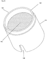
- Figures 9 and 10 each show a hollow tubular section 101, where the definition hollow "tubular” means a hollow component with any cross-section, and therefore not only circular (as in the case shown) but also, for example, square or polygonal in general, elliptical, etc.
- Each section 101 therefore comprises an outside wall 102 extending along a direction parallel to the longitudinal axis of symmetry thereof between a first end portion 103 and a second end portion 104 opposite to said first end portion 103, where the second end portion 104 is tapered or in any case shaped so as to be housed in the first end portion 103 (of a second section 201), the sections 101 therefore being adapted to be mutually connected as shown in figure 3 , i.e., by form and dimension interference between said second end portion 104 of a hollow tubular section 101 with said first end portion 103 of an adjacent hollow tubular section 101.
- each section 101 comprises a filtering net or mesh 105 arranged transversely (with respect to the longitudinal axis of symmetry) and including a plurality of micro holes.
- the filtering net or mesh 105 is made of polyester (PES), where embodiments are possible in which the outside wall 102 is made of a different plastic material, in particular of Polystyrene.
- the flowing of breeding water (maintenance or housing) in the hollow container 110 between the upstream end 111 and the downstream end 112 results in the capture by each net or mesh 105 of organic material and/or inorganic material possibly present in the water, and in particular in the forming, on one or more of the meshes or nets 105, of a film or layer of organic and/or inorganic material, the forming of said film or layer being particularly promoted by both the choice of the size of the micro holes, and by the fact that at least the mesh 105 is made of polyester (PES).
- PES polyester
- the dimension of the micro holes varies to decrease from the mesh 105 of the end section 101 further upstream to the mesh 105 of the end section 101 further downstream.
- the dimension (diameter) of the through holes of the filtering mesh 105 of the first hollow tubular section 101 further upstream is between 1750 and 2150 ⁇ m
- the dimension of the through holes of the filtering mesh 105 of the second (intermediate) hollow tubular section 101 is between 55 and 155 ⁇ m
- the dimension of the through holes of the filtering mesh 105 of the third hollow tubular section further downstream is between 4 and 10 ⁇ m.
- the main hollow body 110 comprises four sections 101 arranged in succession and mutually connected to form the hollow body 110; in this case, the dimension (diameter) of the through holes of the filtering mesh 105 of the first hollow tubular section 101 further upstream is between 1750 and 2150 ⁇ m, the dimension of the through holes of the filtering mesh 105 of the second (intermediate) hollow tubular section 101 is between 55 and 155 ⁇ m, the dimension of the through holes of the filtering mesh 105 of the third (intermediate) hollow tubular section is between 4 and 10 ⁇ m, whereas the mesh 105 of the fourth section 101 further downstream corresponds to that of the mesh 105 of the third section 101 or, alternatively, the fourth section 101 does not comprise the filtering mesh 105.
- the planar dimension of the mesh 105 it is between 400 and 600 sq. mm.
- each section 101 comprises a through notch 106 extending from the free edge of the first end portion 103 parallel to the longitudinal extension direction of the section 101 (of the outside wall 102) and connects the inside of the section 101 with the outside; in particular, the longitudinal extension of the notch 106 is larger than the longitudinal extension of the tapered portion 104 so that, with the sections 101 mutually connected to form the hollow body 110, each notch 106 is not completely obstructed by said tapered portion 104 of the adjacent section 101, but rather defines a through opening.
- Each notch 106 therefore defines an "overflow" device adapted to discharge any excess water present inside the body 110 to outside the body 110 (for example in the case in which one or more meshes 106 are obstructed by the film or layer of organic and/or inorganic material).
- the device 100 comprises a hollow outer container 120 inside which the hollow body 110 is housed.
- the container 120 comprises a hollow element 121 closed at opposite ends by a first plug 122 and a second plug 123, respectively, made of elastic material, for example silicone.
- the first upper plug 122 is shaped to define a first annular seat 128 in which, with the plug 122 in the closed position, the free edge of the upstream end of the container 110 is engaged by form and dimension interference, as well as a second annular seat 124 in which the free edge of the end section 101 further upstream of the body 110 is engaged, said first seat 128 and second seat 124 therefore being concentric with a diameter corresponding to the diameter of the container 120 and respectively of the body 110.
- the plug 122 further comprises a central through opening 125 and means (not depicted) for applying the device 100 to a pipe 203 (as depicted in figures 2a and 2b ), where the through opening 125 allows the introduction of water into the device 100, in particular into the body 110 and/or into the hollow container 120.
- the plug 123 on the part thereof comprises an annular seat 126 in which, with the plug 123 in the closed position, the free edge of the downstream end of the container 110 is engaged by form and dimension interference, where the plug 123 comprises a through opening 127 for the discharge or outflow of water from the device 100.
- the use of the device 100 for microbiological screening of the maintenance water of aquatic animals can be summarized as follows.
- the forming of one or more layers or films of organic and/or inorganic material can be monitored visually through the container 120 (in transparent material), where upon the forming of one or more layers which can be subjected to laboratory analysis, the device 100 is removed from the apparatus 200 and the sections 101, once the body 110 has been extracted from the container 120, are separated and subjected to analysis of the respective film or layer.
- the device 100 can be removed from the apparatus 200 according to predefined deadlines, regardless of the degree of accumulation of organic and/or inorganic material on one or more of the meshes or nets 105.
- a device for the microbiological screening of the maintenance water of aquatic animal species, in particular laboratory animals, and an apparatus for housing said aquatic animal species are provided, where:
- the device simultaneously allows to concentrate organic and inorganic material coming from the aquatic colony environment or part thereof over time and promote the development of biofilms in an isolated manner.
- the device allows the environmental microbiological monitoring of a defined microbiological unit as a whole.
- the device promotes the development of the biofilm.
- the device offers the ability to filter an amount of recirculated water over time sufficient for the retention of microorganisms or fractions thereof identifiable by PCR.
Landscapes
- Life Sciences & Earth Sciences (AREA)
- Environmental Sciences (AREA)
- Chemical & Material Sciences (AREA)
- Health & Medical Sciences (AREA)
- Marine Sciences & Fisheries (AREA)
- Animal Husbandry (AREA)
- Biodiversity & Conservation Biology (AREA)
- General Physics & Mathematics (AREA)
- General Health & Medical Sciences (AREA)
- Pathology (AREA)
- Immunology (AREA)
- Physics & Mathematics (AREA)
- Analytical Chemistry (AREA)
- Biochemistry (AREA)
- Chemical Kinetics & Catalysis (AREA)
- Engineering & Computer Science (AREA)
- Medicinal Chemistry (AREA)
- Food Science & Technology (AREA)
- Farming Of Fish And Shellfish (AREA)
- Zoology (AREA)
- Apparatus Associated With Microorganisms And Enzymes (AREA)
Abstract
Description
- The present invention relates to the technical field of breeding (housing) laboratory animals, in particular laboratory aquatic animal species. In particular, the present invention relates to the microbiological screening of the breeding water of said laboratory aquatic animal species. In detail, the present invention relates to a device for the microbiological screening of water in systems and/or equipment for housing aquatic animal species. The present invention also relates to an apparatus for breeding laboratory aquatic animal species provided with said device.
- According to the most widespread and commonly adopted solutions, laboratory aquatic animal species are bred in apparatuses including a plurality of trays, arranged for example on the shelves of a shelving, and each intended to house a predefined number of small fish, where the breeding water is circulated between the trays by a special circuit including pipes, pumps, filters and devices adapted to the purpose, substantially known per se and therefore not described in detail for synthesis purposes.
- The need to avoid and/or prevent and/or remove, in apparatuses of the aforementioned type, any contamination of the maintenance water which could seriously compromise the health of the animals is therefore evident, where the preventive and/or diagnostic measures most commonly adopted involve the use of animals known as "sentinel" or "colony" animals.
- Programs using sentinel fish are developed and designed to maximize the transmission of pathogens to a small group of animals exposed to wastewater from recirculating housing plants.
- The sentinel fish can be identified from the colony itself, they can be particularly elderly individuals or they can be specifically selected to be used for health monitoring analyses. To date, specific genetic lines for broad-spectrum health monitoring are difficult to identify.
- These specimens must be exposed to recirculating wastewater for a minimum period of three months and be analyzed at least 2/4 times a year.
- It is possible to use a combination of analysis methods on fish used as sentinels, which include, by way of non-limiting example, microbiological, PCR and histopathological techniques.
- However, the use of sentinel animals (hereinafter "the sentinels") has several drawbacks which the patentee of the present application intends to overcome or at least minimize.
- Firstly, a first drawback encountered in the use of sentinel animals is related to the non-negligible risk of transmission of the various pathogens from infected to non-infected subjects, and therefore to the risk of promoting the spread of microbiological positivity.
- Furthermore, the need to sacrifice animals dedicated to the purpose (sentinels) or colony animals has a significant impact at the ethical level and therefore in the operational choices for health screening.
- Furthermore, the use of animals for microbiological screening has an often non-negligible economic impact due to the maintenance thereof for more or less prolonged periods.
- Finally, it cannot be underestimated that a limited number of subjects from the colony are sampled for microbiological screening purposes, where this number is not necessarily representative of the prevalence in the colony of all possible and known infections in aquatic species. The number of subjects to be sampled as a function of statistical confidence levels to ensure that at least one subject sampled is positive for the microorganism sought is dependent on the prevalence of the infection in the colony, a prevalence which is sometimes very low and in many cases not even known.
- Alternative solutions to the use of sentinel animals according to the background art include the extemporaneous sampling of biological material from different points of the housing system. However, even these extemporaneous sampling solutions do not allow a reliable and low cost microbiological screening of the housing water, nor in an easily implemented manner.
- Therefore, the primary object of the present invention is to provide a solution which allows to overcome or at least reduce the disadvantages and/or drawbacks encountered in the microbiological screening and/or monitoring techniques according to the background art.
- In particular, the object of the present invention is to provide a microbiological screening and/or monitoring device which ensures reliable monitoring of the housing water of aquatic animal species, in particular laboratory animals, which is achievable and implementable at low costs and according to simple, if not immediate, methods which do not involve the use of sentinel animals, and which last but not least prevents the transmission of pathogens.
- The present invention arises from the general consideration according to which the above objects can be achieved and the disadvantages found in the solutions according to the background art can be effectively reduced by promoting the forming of a film or substrate of inorganic material and/or inorganic material coming from the housing water, where said film is easily withdrawable and adapted to be subjected to laboratory analyses.
- The present invention has therefore been conceived with the aim of favoring the accumulation in the form of film or substrate of organic and/or inorganic material possibly present in the housing water, and to allow easier handling and without risk of contamination of said film or substrate.
- Therefore, based on both of the preset objects summarized above and the above considerations and/or the problems or disadvantages encountered in the solutions according to the background art, the present invention relates to a device according to the
main claim 1 and an apparatus according to the main claim 13, embodiments of the present invention being defined by the dependent claims. - According to an embodiment described, the microbiological screening device according to the present invention is adapted to be applied to an apparatus for housing (breeding, maintenance or housing) aquatic animal species, in particular laboratory animals, so as to intercept at least in part the housing water circulating in the apparatus, as well as in order to capture organic and/or inorganic material, if present in the housing water, in particular by favoring the accumulation of said organic and/or inorganic material in the form of film or substrate which is easily to handle and subject to laboratory exams and/or tests.
- According to a described embodiment, the microbiological screening device, in particular for the collection and concentration of organic and inorganic material present in a liquid, comprises a plurality of hollow tubular sections arranged one following the other and mutually connected to define a main hollow tubular body adapted to allow the flowing of a fluid between a first end thereof and a second end thereof opposite to said first end thereof, where every hollow tubular section comprises a filtering mesh arranged substantially transversely to the longitudinal extension direction thereof and comprising a plurality of through holes; where the size of said through holes of each of said filtering meshes is larger than that of the through holes of the subsequent filtering mesh in the direction from said first end to said second end.
- According to a described embodiment, each of said filtering meshes is made of polyester and is adapted to promote the forming of a biofilm usable for microbiological investigations.
- According to a described embodiment, the outside wall of each of said hollow tubular sections, i.e., the outside wall supporting the filtering mesh, is made entirely of polystyrene.
- According to a described embodiment, said hollow tubular sections are mutually connected by form and dimension interference and mutually disconnectable.
- According to a described embodiment, each of said hollow tubular sections comprises a first end portion and a second end portion opposite to said first end portion, where said first end portion of each of said sections is adapted to accommodate by form and dimension interference said second end portion of the adjacent hollow tubular section in the direction from said first end to said second end of said main hollow body.
- According to a described embodiment, each of said hollow tubular sections comprises an overflow device adapted to allow the flowing of said liquid from the inside of said hollow tubular section to the outside of said hollow tubular section.
- According to a described embodiment, each of said overflow devices comprises a through notch made on the outside wall of the respective hollow tubular section, where said through notch extends from the free edge of said first end portion.
- According to a described embodiment, said device comprises a hollow container, where said main hollow body formed by said hollow tubular sections is accommodated inside said hollow container.
- According to a described embodiment, said device comprises a first plug and a second plug removably applied to a first end portion of said hollow container and to the second end portion of said hollow container, respectively, opposite to said first end portion thereof, where said first plug and second plug comprise a first through hole and a second through hole adapted to allow the intake of said liquid into said hollow container and the outflow of said liquid from said hollow container, respectively.
- According to a described embodiment, said hollow container comprises means adapted to allow the application thereof to a main pipe and to put in communication the inside of said main pipe with the inside of said main hollow body so as to allow the flowing of said liquid from said main pipe into said main hollow body.
- According to a described embodiment, said device comprises three hollow tubular sections, the dimension (diameter) of the through holes of the filtering mesh of a first hollow tubular section is between 1750 and 2150 µm, where the dimension (diameter) of the through holes of the filtering mesh of the second hollow tubular section adjacent to said first hollow tubular section is between 55 and 155 µm, and where the dimension (diameter) of the through holes of the filtering mesh of the third hollow tubular section adjacent to said second hollow tubular section is between 4 and 10 µm.
- According to a described embodiment, said device comprises four hollow tubular sections, where the dimension (diameter) of the through holes of the filtering mesh of a first hollow tubular section is between 1750 and 2150 µm, where the dimension (diameter) of the through holes of the filtering mesh of the second hollow tubular section adjacent to said first hollow tubular section is between 55 and 155 µm, and where the dimension of the through holes of the filtering mesh of the third hollow tubular section adjacent to said second hollow tubular section is between 4 and 10 µm.
- An apparatus for breeding laboratory aquatic animal species is also described, said apparatus comprising a plurality of trays each adapted to contain a predefined amount of a liquid and to house a subpopulation of said animal species, where said trays are mutually connected by means of a circuit adapted to allow the circulation of said liquid between said trays, where said apparatus comprises at least one device according to one of the described embodiments applied to said circuit so as to intercept at least part of the liquid in transit or circulating within said circuit.
- According to a described embodiment, said device is applied to said circuit in a position which allows the flowing by gravity of said liquid within said main hollow body.
- According to a described embodiment, said trays are arranged on a shelving including superimposed shelves.
- A description will be given below of the embodiments of the present invention depicted in the drawings, in which:
-
Figures 1a and 1b each show a perspective view of an apparatus for the maintenance (breeding, housing) of aquatic animal species; -
Figures 2a and 2b show a perspective and sectional view respectively of an application example of the device according to an embodiment of the present invention to an apparatus of the type depicted infigures 1a and 1b ; -
Figure 3 shows a perspective view of the main body of a device according to an embodiment of the present invention; -
Figure 4 shows a perspective view of the hollow container of a device according to an embodiment of the present invention; -
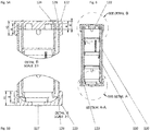
Figures 5a and 5b show detailed sectional views of the device according to an embodiment of the present invention; -
Figure 6 shows a longitudinal sectional view of a device according to an embodiment of the present invention; -
Figure 7 shows a side view of a device according to an embodiment of the present invention; -
Figure 8 shows a top plan view of a device according to an embodiment of the present invention; -
Figures 9 and10 each show a perspective view of a component of a device according to an embodiment of the present invention. - It must be noted that the present invention is not limited to the embodiments described below and depicted in the accompanying drawings; on the contrary, all the variants and/or changes to the embodiments described below and depicted in the accompanying drawings will appear obvious and immediate to a person skilled in the art.
- The present invention finds particularly advantageous application in the microbiological screening of the maintenance water (breeding, housing) of aquatic animal species, in particular for laboratory animals, this therefore being the reason why, in the following, the present invention will be described with particular reference to the applications thereof in the field of breeding (maintenance, housing) aquatic animal species, in particular laboratory animals.
- However, it is worth specifying that the possible applications of the present invention are not limited to those described below. On the contrary, the present invention finds convenient application in all cases in which it is necessary to optimize the screening and/or microbiological monitoring of a liquid, for example water, capable of containing organic and/or inorganic material.
- In
figures 1a and 1b , thereference numeral 200 identifies an apparatus for breeding laboratory aquatic animal species (small fish or the like); as depicted, theapparatus 200 comprises a shelving (a shelf) 201 including a plurality ofshelves 202 arranged mutually in an overlying position, each of saidshelves 202 being adapted to support a plurality of trays (not shown for reasons of clarity) arranged side by side and each adapted to contain a predefined amount of maintenance water and therefore to house a predefined number of aquatic animals (variable according to the volume of the tray and the size of the aquatic animals). The trays are mutually connected by a hydrauliccircuit including pipes 203 and adapted to allow the circulation of water between the trays, the circuit comprising for this purpose devices housed in acompartment 204 of theshelving 201 and including, for example, pumps, filters and devices typical of every hydraulic circuit. - Since both of said devices for circulating water in the circuit (in the pipes and trays) and the methods of circulating the water itself are substantially known, a detailed description is omitted for synthesis purposes.
- As shown in
figures 2a and 2b , adevice 100 according to the present invention is installed along the hydraulic circuit of theapparatus 200; in the particular and non-exclusive case offigures 2a and 2b , thedevice 100 is applied to anelbow 205 of thepipe 203, in particular to ahorizontal section 206 of thepipe 203 so that thedevice 100 is arranged substantially vertically and therefore so that the water in the circuit can be introduced into thedevice 100 and flow out of thedevice 100 substantially by gravity; however, different arrangements are possible in which, for example, thedevice 100 is applied to avertical section 206 of thepipe 203 so as to be oriented along a substantially horizontal direction. Whatever the orientation thereof (vertical or horizontal or oblique), thedevice 100 is applied to the section ofpipe 206 so as to be in hydraulic communication with the circuit of theapparatus 200, i.e., so as to intercept the flowing of water in circulation in the circuit according to the methods explained in more detail below; in practice, with thedevice 100 applied to theapparatus 200, part of the water circulating in theapparatus 200 is introduced into thedevice 100 and discharged from thedevice 100, where the water discharged from thedevice 100 can be reintroduced into the circuit of theapparatus 200 or dispersed or accumulated in a container. - In the following, with reference to
figures 3 to 10 , an embodiment of thedevice 100 will be described, where infigures 3 to 10 component parts of thedevice 100 and/or of theapparatus 200 already described with reference to other figures are identified by the same reference numerals. -
Figures 9 and10 each show ahollow tubular section 101, where the definition hollow "tubular" means a hollow component with any cross-section, and therefore not only circular (as in the case shown) but also, for example, square or polygonal in general, elliptical, etc. - Each
section 101 therefore comprises anoutside wall 102 extending along a direction parallel to the longitudinal axis of symmetry thereof between a first end portion 103 and asecond end portion 104 opposite to said first end portion 103, where thesecond end portion 104 is tapered or in any case shaped so as to be housed in the first end portion 103 (of a second section 201), thesections 101 therefore being adapted to be mutually connected as shown infigure 3 , i.e., by form and dimension interference between saidsecond end portion 104 of ahollow tubular section 101 with said first end portion 103 of an adjacent hollowtubular section 101. - The mutual connection, in the manner described above, of a plurality of hollow tubular sections 101 (four in number in the non-limiting example of
figure 3 ), results in the forming of a hollowtubular body 110 adapted to allow the passage of a liquid (in particular water) therein, between theupstream end 111 and the opposite end, downstream 112. Furthermore, as depicted infigures 9 and10 , eachsection 101 comprises a filtering net or mesh 105 arranged transversely (with respect to the longitudinal axis of symmetry) and including a plurality of micro holes. The filtering net ormesh 105 is made of polyester (PES), where embodiments are possible in which theoutside wall 102 is made of a different plastic material, in particular of Polystyrene. - In use, the flowing of breeding water (maintenance or housing) in the
hollow container 110 between theupstream end 111 and thedownstream end 112, results in the capture by each net or mesh 105 of organic material and/or inorganic material possibly present in the water, and in particular in the forming, on one or more of the meshes ornets 105, of a film or layer of organic and/or inorganic material, the forming of said film or layer being particularly promoted by both the choice of the size of the micro holes, and by the fact that at least themesh 105 is made of polyester (PES). - In this regard, according to the present invention, the dimension of the micro holes varies to decrease from the
mesh 105 of theend section 101 further upstream to themesh 105 of theend section 101 further downstream. - In particular, in the case of a main
hollow body 110 formed by threesections 101 arranged in succession and mutually connected, the dimension (diameter) of the through holes of thefiltering mesh 105 of the firsthollow tubular section 101 further upstream is between 1750 and 2150 µm, the dimension of the through holes of thefiltering mesh 105 of the second (intermediate)hollow tubular section 101 is between 55 and 155 µm, and the dimension of the through holes of thefiltering mesh 105 of the third hollow tubular section further downstream is between 4 and 10 µm. - However, embodiments are also possible in which the main
hollow body 110 comprises foursections 101 arranged in succession and mutually connected to form thehollow body 110; in this case, the dimension (diameter) of the through holes of thefiltering mesh 105 of the firsthollow tubular section 101 further upstream is between 1750 and 2150 µm, the dimension of the through holes of thefiltering mesh 105 of the second (intermediate)hollow tubular section 101 is between 55 and 155 µm, the dimension of the through holes of thefiltering mesh 105 of the third (intermediate) hollow tubular section is between 4 and 10 µm, whereas themesh 105 of thefourth section 101 further downstream corresponds to that of themesh 105 of thethird section 101 or, alternatively, thefourth section 101 does not comprise thefiltering mesh 105. In regard to the planar dimension of themesh 105, it is between 400 and 600 sq. mm. - Again as depicted, each
section 101 comprises a throughnotch 106 extending from the free edge of the first end portion 103 parallel to the longitudinal extension direction of the section 101 (of the outside wall 102) and connects the inside of thesection 101 with the outside; in particular, the longitudinal extension of thenotch 106 is larger than the longitudinal extension of the taperedportion 104 so that, with thesections 101 mutually connected to form thehollow body 110, eachnotch 106 is not completely obstructed by saidtapered portion 104 of theadjacent section 101, but rather defines a through opening. Eachnotch 106 therefore defines an "overflow" device adapted to discharge any excess water present inside thebody 110 to outside the body 110 (for example in the case in which one ormore meshes 106 are obstructed by the film or layer of organic and/or inorganic material). - The figures also show that the
device 100 comprises a hollowouter container 120 inside which thehollow body 110 is housed. Thecontainer 120 comprises ahollow element 121 closed at opposite ends by afirst plug 122 and asecond plug 123, respectively, made of elastic material, for example silicone. - The first
upper plug 122 is shaped to define a firstannular seat 128 in which, with theplug 122 in the closed position, the free edge of the upstream end of thecontainer 110 is engaged by form and dimension interference, as well as a secondannular seat 124 in which the free edge of theend section 101 further upstream of thebody 110 is engaged, saidfirst seat 128 andsecond seat 124 therefore being concentric with a diameter corresponding to the diameter of thecontainer 120 and respectively of thebody 110. Theplug 122 further comprises a central throughopening 125 and means (not depicted) for applying thedevice 100 to a pipe 203 (as depicted infigures 2a and 2b ), where the throughopening 125 allows the introduction of water into thedevice 100, in particular into thebody 110 and/or into thehollow container 120. - The
plug 123 on the part thereof comprises anannular seat 126 in which, with theplug 123 in the closed position, the free edge of the downstream end of thecontainer 110 is engaged by form and dimension interference, where theplug 123 comprises a throughopening 127 for the discharge or outflow of water from thedevice 100. - The use of the
device 100 for microbiological screening of the maintenance water of aquatic animals can be summarized as follows. - With the
device 100 applied to theapparatus 200 so as to intercept at least part of the water circulating in the circuit of the apparatus itself 200, the continuous flowing of water through thedevice 100, entering through thehole 125 and exiting through thehole 127, and therefore through the mainhollow body 110, results in the accumulation on the meshes 105 (one or more) of thesections 101, of a layer of organic and/or inorganic material. The forming of one or more layers or films of organic and/or inorganic material can be monitored visually through the container 120 (in transparent material), where upon the forming of one or more layers which can be subjected to laboratory analysis, thedevice 100 is removed from theapparatus 200 and thesections 101, once thebody 110 has been extracted from thecontainer 120, are separated and subjected to analysis of the respective film or layer. Alternatively, thedevice 100 can be removed from theapparatus 200 according to predefined deadlines, regardless of the degree of accumulation of organic and/or inorganic material on one or more of the meshes or nets 105. - We have thus demonstrated by means of the detailed description of the embodiments of the present invention shown in the drawings given above that the present invention makes it possible to obtain the desired objects and to overcome or at least limit the drawbacks found in the background art.
- In particular, by means of the present invention a device for the microbiological screening of the maintenance water of aquatic animal species, in particular laboratory animals, and an apparatus for housing said aquatic animal species are provided, where:
- the
device 100 ensures reliable monitoring of the housing water of aquatic animal species, in particular laboratory animals; - it is achievable and implementable at low cost and in simple, if not immediate, methods;
- it does not involve the use of sentinel animals;
- it avoids or at least limits the risk of transmission of pathogens.
- The device simultaneously allows to concentrate organic and inorganic material coming from the aquatic colony environment or part thereof over time and promote the development of biofilms in an isolated manner.
- The device allows the environmental microbiological monitoring of a defined microbiological unit as a whole.
- Through the use of a specific plastic material for the nets or meshes 105, the device promotes the development of the biofilm.
- The device offers the ability to filter an amount of recirculated water over time sufficient for the retention of microorganisms or fractions thereof identifiable by PCR. Although the present invention is explained above by means of a detailed description of the embodiments thereof shown in the drawings, the present invention is obviously not limited to the embodiments described above and shown on the drawings; on the contrary, all the variants and/or changes to the embodiments described and shown on the accompanying drawings will appear obvious and immediate to a person skilled in the art.
- The scope of protection of the present invention is thus defined by the claims.
Claims (15)
- A microbiological screening device (100), in particular for collection and concentration of organic and inorganic matter present in a liquid, said device (100) including a plurality of hollow tubular sections (101) arranged one following the other, and reciprocally connected, to define a main hollow tubular body (110) adapted to allow the flowing of a fluid between a first end (111) thereof and a second end (112) thereof, opposite to said one first end (111) thereof, wherein every hollow tubular section (101) comprises a filtering mesh or net (105) arranged substantially transversely to the longitudinal extension direction thereof and including a plurality of through holes; characterized in that, the size of said through holes of each of said filtering meshes (105) is larger than that of the through holes of the filtering mesh (105) of the next hollow tubular section (101) in the direction from said fist end (111) to said second end (112).
- A device (100) according to claim 1, characterized in that each of said filtering meshes (105) is made of polyester (PES) and is adapted to promote the forming of a biofilm usable for microbiological investigations.
- A device (100) according to claim 1 or 2, characterized in that, parts of each of said hollow tubular sections (101) other than said filtering mesh (105) are made of Polystyrene.
- A device (100) according to one of claims 1 to 3, characterized in that said hollow tubular sections (101) are mutually connected by form and dimension interference and adapted to be mutually disconnected.
- A device (100) according to claim 4, characterized in that each of said hollow tubular sections (101) comprises a first end portion (103) and a second end portion (104), opposite to said first end portion (103), and in that, said first end portion (103) of each of said sections (101) is adapted to accommodate by form and dimension interference said second end portion (104) of the adjacent hollow tubular section (101) in the direction from said first end (111) to said second end (112) of said main hollow body (110).
- A device (100) according to one of claims 1 to 5, characterized in that each of said hollow tubular sections (101) comprises an overflow device (106) adapted to allow the flowing of said liquid from the inside of said hollow tubular section (101) to the outside of said hollow tubular section (101).
- A device (100) according to claim 6, characterized in that each of said overflow devices (106) comprises a through notch (106) made on the outside wall (102) of the respective hollow tubular section (101), and in that, said through notch (106) extends from the free edge of said first end portion (103).
- A device (100) according to one of claims 1 to 7, characterized in that said device (100) comprises a hollow container (120), and in that said main hollow body (110) formed by said hollow tubular sections (101) is housed within said hollow container (120).
- A device (100) according to claim 8, characterized in that said device (100) comprises a first plug (122) and a second plug (123) removably applied to a first end portion of said hollow container (120) and to the second end portion of said hollow container (120), respectively, opposite to said first end portion thereof, and in that said first plug (122) and second plug (123) include a first through hole (125) and a second through hole (127), respectively, adapted to allow the intake of said liquid into said hollow container (120) and the outflow of said liquid from said hollow container (120), respectively.
- A device (100) according to one of claims 8 and 9, characterized in that said hollow container (120) comprises means adapted to permit the application thereof to a main pipe (203) and to put in communication the inside of said main pipe (203) with the inside the said main hollow body (110) so as to allow the flowing of said liquid from said main pipe (203) into said main hollow body (110).
- A device (100) according to one of claims 1 to 10, characterized in that it comprises three hollow tubular sections (101), in that the diameter of the through holes of the filtering mesh (105) of a first hollow tubular section (101) is between 1750 and 2150 µm, in that the diameter of the through holes of the filtering mesh (105) of the second hollow tubular section (101) adjacent to said first hollow tubular section (101) is between 55 and 155 µm, and in that the diameter of the through holes of the filtering mesh (105) of the third hollow tubular section (101) adjacent to said second hollow tubular section is between 4 and 10 µm.
- Device according to one of claims 1 to 10, characterized in that it comprises four hollow tubular sections, in that the diameter of the through holes of the filtering mesh (105) of a first hollow tubular section (101) is between 1750 and 2150 µm, in that the diameter of the through holes of the filtering mesh (105) of the second hollow tubular section (101) adjacent to said first hollow tubular section (101) is between 55 and 155 µm, and in that the diameter of the through holes of the filtering mesh (105) of the third hollow tubular section (101) adjacent to said second hollow tubular section is between 4 and 10 µm.
- An apparatus (200) for breeding laboratory aquatic animal species, said apparatus (200) including a plurality of trays each adapted to contain a predefined amount of a liquid and to house a sub-population of these animal species, wherein said trays are reciprocally connected by means of a circuit adapted to allow the circulation of said liquid between said trays, characterized in that said apparatus (200) comprises at least a device (100) according to one of claims 1 to 12 applied to said circuit so as to intercept at least part of the liquid in transit within said circuit.
- An apparatus (200) according to claim 13, characterized in that said device (100) is applied to said circuit in a position that allows the flowing by gravity of said liquid within said main hollow body (110).
- An apparatus (200) according to one of claims 13 to 14, characterized in that said trays are arranged on a storage rack (201) comprising superimposed shelves (202).
Applications Claiming Priority (1)
| Application Number | Priority Date | Filing Date | Title |
|---|---|---|---|
| IT102020000007180A IT202000007180A1 (en) | 2020-04-03 | 2020-04-03 | MICROBIOLOGICAL SCREENING DEVICE, IN PARTICULAR FOR THE COLLECTION AND CONCENTRATION OF ORGANIC AND INORGANIC MATERIAL PRESENT IN A LIQUID, AND EQUIPMENT FOR BREEDING LABORATORY AQUATIC ANIMALS EQUIPPED WITH THIS DEVICE |
Publications (3)
| Publication Number | Publication Date |
|---|---|
| EP3889600A1 true EP3889600A1 (en) | 2021-10-06 |
| EP3889600B1 EP3889600B1 (en) | 2025-10-22 |
| EP3889600C0 EP3889600C0 (en) | 2025-10-22 |
Family
ID=71094707
Family Applications (1)
| Application Number | Title | Priority Date | Filing Date |
|---|---|---|---|
| EP21166271.3A Active EP3889600B1 (en) | 2020-04-03 | 2021-03-31 | Microbiological screening device and apparatus for breeding laboratory aquatic animals provided with said device |
Country Status (4)
| Country | Link |
|---|---|
| US (1) | US11864538B2 (en) |
| EP (1) | EP3889600B1 (en) |
| CN (1) | CN113491896B (en) |
| IT (1) | IT202000007180A1 (en) |
Citations (3)
| Publication number | Priority date | Publication date | Assignee | Title |
|---|---|---|---|---|
| US20030070975A1 (en) * | 2001-06-11 | 2003-04-17 | Brendan Hogan | Combination filter assembly |
| WO2014182027A1 (en) * | 2013-05-06 | 2014-11-13 | 대한민국(관리부서:국립수산과학원) | Apparatus for suppressing algal bloom occurrence and exterminating pathogens in aquarium, and controller for controlling same |
| US20190141964A1 (en) * | 2017-04-11 | 2019-05-16 | Grand Shrimp, Llc | Aquaculture systems and methods |
Family Cites Families (22)
| Publication number | Priority date | Publication date | Assignee | Title |
|---|---|---|---|---|
| US3832854A (en) * | 1973-07-24 | 1974-09-03 | J Metts | Bottom flow pond level control system |
| US3973519A (en) * | 1974-10-07 | 1976-08-10 | Syntex (U.S.A.) Inc. | Screening device in a closed-loop aquaculture system |
| DK232579A (en) * | 1978-06-06 | 1979-12-07 | Diversey Corp | FILTER AND FILTER ELEMENT FOR USE IN THE FILTER |
| US4816148A (en) * | 1986-12-30 | 1989-03-28 | Hemman Edward B | Multi-stage straining apparatus |
| US4731177A (en) * | 1986-12-30 | 1988-03-15 | Hemman Edward B | Multi-stage straining apparatus |
| US20030104353A1 (en) * | 2001-12-04 | 2003-06-05 | Markus Brielmeier | System and method for health monitoring of aquatic species |
| EP1318398A1 (en) * | 2001-12-04 | 2003-06-11 | GSF-Forschungszentrum für Umwelt und Gesundheit GmbH | System and method for health monitoring of aquatic species |
| GB2422794B (en) * | 2005-02-05 | 2009-04-22 | Diasys Europ Ltd | Filtration device for biological samples |
| US20080141587A1 (en) * | 2006-12-15 | 2008-06-19 | Lawson Guthrie | Planter container inserts |
| FR2911687A1 (en) * | 2007-01-19 | 2008-07-25 | Laurent Simard | Controlling quality of water/aqueous solution introduction in liquid circuit, comprises defining liquid sampling sites on liquid circuit to control physicochemical and/or microbiological characteristics and their threshold values |
| WO2010142004A2 (en) * | 2009-06-10 | 2010-12-16 | Katholieke Universifeit Leuven | Controlled biosecure aquatic farming system in a confined environment |
| US9045353B2 (en) * | 2010-09-04 | 2015-06-02 | Hydros Bottle, Llc | Filtering water bottle |
| EP2554655A1 (en) * | 2011-08-01 | 2013-02-06 | Döhler GmbH | Feeding medium |
| CA2952121A1 (en) * | 2014-06-13 | 2015-12-17 | Childrens' Medical Center Corporation | Products and methods to isolate mitochondria |
| US10016705B2 (en) * | 2015-11-06 | 2018-07-10 | James Hull | Water filtration device for purifying water |
| US11172621B2 (en) * | 2017-03-15 | 2021-11-16 | George Addison Irwin | Modular vertical agriculture assembly to support vegetative growth in the vertical plane |
| IS2993B (en) * | 2017-06-01 | 2018-03-15 | Sæplast Iceland ehf. | Depuration container |
| CN208653850U (en) * | 2018-02-07 | 2019-03-26 | 中国环境科学研究院 | Active Multi-Particle Size Microplastic Sample Synchronous Collection and Separation Device |
| WO2019181106A1 (en) * | 2018-03-19 | 2019-09-26 | 株式会社村田製作所 | Filtration device |
| CN208283114U (en) * | 2018-03-20 | 2018-12-25 | 中国环境科学研究院 | More micro- plastic sample synchronous acquisition devices of partial size in a kind of different depth water body |
| CN112469810B (en) * | 2018-07-03 | 2024-10-11 | 株式会社村田制作所 | Filtration recovery device and filtration recovery method |
| US20220104443A1 (en) * | 2020-10-01 | 2022-04-07 | Mytek International Inc. | Frame structure of aquaponic system assembled by module elements |
-
2020
- 2020-04-03 IT IT102020000007180A patent/IT202000007180A1/en unknown
-
2021
- 2021-03-26 US US17/213,976 patent/US11864538B2/en active Active
- 2021-03-31 EP EP21166271.3A patent/EP3889600B1/en active Active
- 2021-04-06 CN CN202110366526.1A patent/CN113491896B/en active Active
Patent Citations (3)
| Publication number | Priority date | Publication date | Assignee | Title |
|---|---|---|---|---|
| US20030070975A1 (en) * | 2001-06-11 | 2003-04-17 | Brendan Hogan | Combination filter assembly |
| WO2014182027A1 (en) * | 2013-05-06 | 2014-11-13 | 대한민국(관리부서:국립수산과학원) | Apparatus for suppressing algal bloom occurrence and exterminating pathogens in aquarium, and controller for controlling same |
| US20190141964A1 (en) * | 2017-04-11 | 2019-05-16 | Grand Shrimp, Llc | Aquaculture systems and methods |
Non-Patent Citations (2)
| Title |
|---|
| ANONYMOUS: "Plankton Screens with medium diameter from 6 to 2000 m", October 2018 (2018-10-01), XP055765294, Retrieved from the Internet <URL:http://www.aquacare-shop.de/epages/79654597.sf/en_GB/?ObjectPath=/Shops/79654597/Products/Sieb100> [retrieved on 20210114] * |
| ANONYMOUS: "SE GP2-9 SET 9-Piece Set of Patented Stackable 13-1/4'' Sifting Pans", 2016, XP055765256, Retrieved from the Internet <URL:http://findgoldtreasure.com/gold-treasure/product/se-gp2-9-set-9-piece-set-of-patented-stackable-13-14-sifting-pans/> [retrieved on 20210114] * |
Also Published As
| Publication number | Publication date |
|---|---|
| US11864538B2 (en) | 2024-01-09 |
| CN113491896B (en) | 2025-10-03 |
| IT202000007180A1 (en) | 2021-10-03 |
| CN113491896A (en) | 2021-10-12 |
| EP3889600B1 (en) | 2025-10-22 |
| US20210307302A1 (en) | 2021-10-07 |
| EP3889600C0 (en) | 2025-10-22 |
Similar Documents
| Publication | Publication Date | Title |
|---|---|---|
| US9226475B2 (en) | Apparatus and method for research and testing of small aquatic species | |
| Kiesecker et al. | Population differences in responses of red‐legged frogs (Rana aurora) to introduced bullfrogs | |
| Peltier | Methods for measuring the acute toxicity of effluents to aquatic organisms | |
| US5605836A (en) | Modular method and device for the evaluation of the ability of biocide to penetrate biofilm | |
| US20030104353A1 (en) | System and method for health monitoring of aquatic species | |
| WO2013073069A1 (en) | Cage for breeding small animals | |
| BR112017013016B1 (en) | Device and methods for detecting plant pathogens | |
| Doerr et al. | Salinity selection by juvenile brown shrimp (Farfantepenaeus aztecus) and white shrimp (Litopenaeus setiferus) in a gradient tank | |
| Mocho et al. | Environmental screening of Aeromonas hydrophila, Mycobacterium spp., and Pseudocapillaria tomentosa in zebrafish systems | |
| US11864538B2 (en) | Microbiological screening device, in particular for the collection and concentration of organic and inorganic material present in a liquid, and apparatus for breeding laboratory aquatic animals provided with said device | |
| Soriano et al. | Determination of organic contaminants in L'Albufera Natural Park using microporous polyethylene tube passive samplers: An environmental risk assessment | |
| Shutler et al. | Leukocyte profiles of northern leopard frogs, Lithobates pipiens, exposed to pesticides and hematozoa in agricultural wetlands | |
| de Oliveira-Lima et al. | Effect of benzophenone-3 on the blood cells of zebrafish (Danio rerio) | |
| Brown et al. | Maternal body size influences offspring immune configuration in an oviparous snake | |
| Wepener | Active biomonitoring | |
| Rasgele et al. | Assessment of the genotoxicity of propineb in mice bone marrow cells using micronucleus assay | |
| EP1318398A1 (en) | System and method for health monitoring of aquatic species | |
| George et al. | Assessment of the probabilistic ecological risk assessment-toxic equivalent combination approach for evaluating pesticide mixture toxicity to zooplankton in outdoor microcosms | |
| US6936463B1 (en) | Method and device for making different thickness of biofilms | |
| CN106353166B (en) | A film processing device | |
| CN201821731U (en) | Experimental rat cage | |
| JP7569088B2 (en) | Cages and Multiple Cage Systems | |
| LaBrie et al. | Using environmental DNA to elucidate range expansion of bigheaded carp in two Missouri River tributaries in eastern South Dakota | |
| Muehlenbein et al. | Health assessment and epidemiology | |
| Hoxie | Microplastics in House Sparrow Nestlings: Evaluation of Nonlethal Methods and Environmental Variation |
Legal Events
| Date | Code | Title | Description |
|---|---|---|---|
| PUAI | Public reference made under article 153(3) epc to a published international application that has entered the european phase |
Free format text: ORIGINAL CODE: 0009012 |
|
| STAA | Information on the status of an ep patent application or granted ep patent |
Free format text: STATUS: THE APPLICATION HAS BEEN PUBLISHED |
|
| AK | Designated contracting states |
Kind code of ref document: A1 Designated state(s): AL AT BE BG CH CY CZ DE DK EE ES FI FR GB GR HR HU IE IS IT LI LT LU LV MC MK MT NL NO PL PT RO RS SE SI SK SM TR |
|
| STAA | Information on the status of an ep patent application or granted ep patent |
Free format text: STATUS: REQUEST FOR EXAMINATION WAS MADE |
|
| 17P | Request for examination filed |
Effective date: 20220406 |
|
| RBV | Designated contracting states (corrected) |
Designated state(s): AL AT BE BG CH CY CZ DE DK EE ES FI FR GB GR HR HU IE IS IT LI LT LU LV MC MK MT NL NO PL PT RO RS SE SI SK SM TR |
|
| STAA | Information on the status of an ep patent application or granted ep patent |
Free format text: STATUS: EXAMINATION IS IN PROGRESS |
|
| 17Q | First examination report despatched |
Effective date: 20230210 |
|
| P01 | Opt-out of the competence of the unified patent court (upc) registered |
Effective date: 20230525 |
|
| GRAP | Despatch of communication of intention to grant a patent |
Free format text: ORIGINAL CODE: EPIDOSNIGR1 |
|
| STAA | Information on the status of an ep patent application or granted ep patent |
Free format text: STATUS: GRANT OF PATENT IS INTENDED |
|
| RIC1 | Information provided on ipc code assigned before grant |
Ipc: C02F 103/20 20060101ALN20250521BHEP Ipc: G01N 1/40 20060101ALI20250521BHEP Ipc: A01K 63/00 20170101ALI20250521BHEP Ipc: A01K 63/04 20060101ALI20250521BHEP Ipc: G01N 33/18 20060101AFI20250521BHEP |
|
| RIC1 | Information provided on ipc code assigned before grant |
Ipc: C02F 103/20 20060101ALN20250526BHEP Ipc: G01N 1/40 20060101ALI20250526BHEP Ipc: A01K 63/00 20170101ALI20250526BHEP Ipc: A01K 63/04 20060101ALI20250526BHEP Ipc: G01N 33/18 20060101AFI20250526BHEP |
|
| INTG | Intention to grant announced |
Effective date: 20250606 |
|
| GRAS | Grant fee paid |
Free format text: ORIGINAL CODE: EPIDOSNIGR3 |
|
| GRAA | (expected) grant |
Free format text: ORIGINAL CODE: 0009210 |
|
| STAA | Information on the status of an ep patent application or granted ep patent |
Free format text: STATUS: THE PATENT HAS BEEN GRANTED |
|
| AK | Designated contracting states |
Kind code of ref document: B1 Designated state(s): AL AT BE BG CH CY CZ DE DK EE ES FI FR GB GR HR HU IE IS IT LI LT LU LV MC MK MT NL NO PL PT RO RS SE SI SK SM TR |
|
| REG | Reference to a national code |
Ref country code: CH Ref legal event code: F10 Free format text: ST27 STATUS EVENT CODE: U-0-0-F10-F00 (AS PROVIDED BY THE NATIONAL OFFICE) Effective date: 20251022 Ref country code: GB Ref legal event code: FG4D |
|
| REG | Reference to a national code |
Ref country code: CH Ref legal event code: R17 Free format text: ST27 STATUS EVENT CODE: U-0-0-R10-R17 (AS PROVIDED BY THE NATIONAL OFFICE) Effective date: 20251105 |
|
| REG | Reference to a national code |
Ref country code: DE Ref legal event code: R096 Ref document number: 602021040710 Country of ref document: DE |
|
| REG | Reference to a national code |
Ref country code: IE Ref legal event code: FG4D |
|
| U01 | Request for unitary effect filed |
Effective date: 20251111 |
|
| U07 | Unitary effect registered |
Designated state(s): AT BE BG DE DK EE FI FR IT LT LU LV MT NL PT RO SE SI Effective date: 20251117 |
|
| P04 | Withdrawal of opt-out of the competence of the unified patent court (upc) registered |
Free format text: CASE NUMBER: UPC_APP_326248_1/2023 Effective date: 20251117 |
|
| U20 | Renewal fee for the european patent with unitary effect paid |
Year of fee payment: 6 Effective date: 20260209 |
|
| REG | Reference to a national code |
Ref country code: CH Ref legal event code: U11 Free format text: ST27 STATUS EVENT CODE: U-0-0-U10-U11 (AS PROVIDED BY THE NATIONAL OFFICE) Effective date: 20260401 |
|
| PGFP | Annual fee paid to national office [announced via postgrant information from national office to epo] |
Ref country code: GB Payment date: 20260209 Year of fee payment: 6 |
|
| PG25 | Lapsed in a contracting state [announced via postgrant information from national office to epo] |
Ref country code: ES Free format text: LAPSE BECAUSE OF FAILURE TO SUBMIT A TRANSLATION OF THE DESCRIPTION OR TO PAY THE FEE WITHIN THE PRESCRIBED TIME-LIMIT Effective date: 20251022 |
|
| PG25 | Lapsed in a contracting state [announced via postgrant information from national office to epo] |
Ref country code: NO Free format text: LAPSE BECAUSE OF FAILURE TO SUBMIT A TRANSLATION OF THE DESCRIPTION OR TO PAY THE FEE WITHIN THE PRESCRIBED TIME-LIMIT Effective date: 20260122 |
|
| PG25 | Lapsed in a contracting state [announced via postgrant information from national office to epo] |
Ref country code: HR Free format text: LAPSE BECAUSE OF FAILURE TO SUBMIT A TRANSLATION OF THE DESCRIPTION OR TO PAY THE FEE WITHIN THE PRESCRIBED TIME-LIMIT Effective date: 20251022 |
|
| PG25 | Lapsed in a contracting state [announced via postgrant information from national office to epo] |
Ref country code: RS Free format text: LAPSE BECAUSE OF FAILURE TO SUBMIT A TRANSLATION OF THE DESCRIPTION OR TO PAY THE FEE WITHIN THE PRESCRIBED TIME-LIMIT Effective date: 20260122 |
|
| PG25 | Lapsed in a contracting state [announced via postgrant information from national office to epo] |
Ref country code: IS Free format text: LAPSE BECAUSE OF FAILURE TO SUBMIT A TRANSLATION OF THE DESCRIPTION OR TO PAY THE FEE WITHIN THE PRESCRIBED TIME-LIMIT Effective date: 20260222 |
|
| PG25 | Lapsed in a contracting state [announced via postgrant information from national office to epo] |
Ref country code: PL Free format text: LAPSE BECAUSE OF FAILURE TO SUBMIT A TRANSLATION OF THE DESCRIPTION OR TO PAY THE FEE WITHIN THE PRESCRIBED TIME-LIMIT Effective date: 20251022 |
|
| PG25 | Lapsed in a contracting state [announced via postgrant information from national office to epo] |
Ref country code: SM Free format text: LAPSE BECAUSE OF FAILURE TO SUBMIT A TRANSLATION OF THE DESCRIPTION OR TO PAY THE FEE WITHIN THE PRESCRIBED TIME-LIMIT Effective date: 20251022 |
|
| PGFP | Annual fee paid to national office [announced via postgrant information from national office to epo] |
Ref country code: CH Payment date: 20260401 Year of fee payment: 6 |
|
| PG25 | Lapsed in a contracting state [announced via postgrant information from national office to epo] |
Ref country code: CZ Free format text: LAPSE BECAUSE OF FAILURE TO SUBMIT A TRANSLATION OF THE DESCRIPTION OR TO PAY THE FEE WITHIN THE PRESCRIBED TIME-LIMIT Effective date: 20251022 |
|
| PG25 | Lapsed in a contracting state [announced via postgrant information from national office to epo] |
Ref country code: SK Free format text: LAPSE BECAUSE OF FAILURE TO SUBMIT A TRANSLATION OF THE DESCRIPTION OR TO PAY THE FEE WITHIN THE PRESCRIBED TIME-LIMIT Effective date: 20251022 |