EP3889561B1 - Method and system for detecting and identifying vibration on basis of optical fiber signal feature to determine time-space - Google Patents
Method and system for detecting and identifying vibration on basis of optical fiber signal feature to determine time-space Download PDFInfo
- Publication number
- EP3889561B1 EP3889561B1 EP19905331.5A EP19905331A EP3889561B1 EP 3889561 B1 EP3889561 B1 EP 3889561B1 EP 19905331 A EP19905331 A EP 19905331A EP 3889561 B1 EP3889561 B1 EP 3889561B1
- Authority
- EP
- European Patent Office
- Prior art keywords
- vibration
- feature
- represented
- following equation
- equation
- Prior art date
- Legal status (The legal status is an assumption and is not a legal conclusion. Google has not performed a legal analysis and makes no representation as to the accuracy of the status listed.)
- Active
Links
Images



Classifications
-
- G—PHYSICS
- G01—MEASURING; TESTING
- G01H—MEASUREMENT OF MECHANICAL VIBRATIONS OR ULTRASONIC, SONIC OR INFRASONIC WAVES
- G01H9/00—Measuring mechanical vibrations or ultrasonic, sonic or infrasonic waves by using radiation-sensitive means, e.g. optical means
- G01H9/004—Measuring mechanical vibrations or ultrasonic, sonic or infrasonic waves by using radiation-sensitive means, e.g. optical means using fibre optic sensors
-
- G—PHYSICS
- G06—COMPUTING OR CALCULATING; COUNTING
- G06F—ELECTRIC DIGITAL DATA PROCESSING
- G06F18/00—Pattern recognition
- G06F18/20—Analysing
- G06F18/21—Design or setup of recognition systems or techniques; Extraction of features in feature space; Blind source separation
- G06F18/213—Feature extraction, e.g. by transforming the feature space; Summarisation; Mappings, e.g. subspace methods
- G06F18/2135—Feature extraction, e.g. by transforming the feature space; Summarisation; Mappings, e.g. subspace methods based on approximation criteria, e.g. principal component analysis
-
- G—PHYSICS
- G06—COMPUTING OR CALCULATING; COUNTING
- G06F—ELECTRIC DIGITAL DATA PROCESSING
- G06F18/00—Pattern recognition
- G06F18/20—Analysing
- G06F18/21—Design or setup of recognition systems or techniques; Extraction of features in feature space; Blind source separation
- G06F18/214—Generating training patterns; Bootstrap methods, e.g. bagging or boosting
-
- G—PHYSICS
- G06—COMPUTING OR CALCULATING; COUNTING
- G06F—ELECTRIC DIGITAL DATA PROCESSING
- G06F18/00—Pattern recognition
- G06F18/20—Analysing
- G06F18/22—Matching criteria, e.g. proximity measures
-
- G—PHYSICS
- G06—COMPUTING OR CALCULATING; COUNTING
- G06F—ELECTRIC DIGITAL DATA PROCESSING
- G06F18/00—Pattern recognition
- G06F18/20—Analysing
- G06F18/24—Classification techniques
- G06F18/241—Classification techniques relating to the classification model, e.g. parametric or non-parametric approaches
- G06F18/2413—Classification techniques relating to the classification model, e.g. parametric or non-parametric approaches based on distances to training or reference patterns
- G06F18/24133—Distances to prototypes
- G06F18/24137—Distances to cluster centroïds
-
- G—PHYSICS
- G06—COMPUTING OR CALCULATING; COUNTING
- G06F—ELECTRIC DIGITAL DATA PROCESSING
- G06F18/00—Pattern recognition
- G06F18/20—Analysing
- G06F18/24—Classification techniques
- G06F18/243—Classification techniques relating to the number of classes
- G06F18/24323—Tree-organised classifiers
-
- G—PHYSICS
- G06—COMPUTING OR CALCULATING; COUNTING
- G06N—COMPUTING ARRANGEMENTS BASED ON SPECIFIC COMPUTATIONAL MODELS
- G06N20/00—Machine learning
- G06N20/10—Machine learning using kernel methods, e.g. support vector machines [SVM]
-
- G—PHYSICS
- G06—COMPUTING OR CALCULATING; COUNTING
- G06N—COMPUTING ARRANGEMENTS BASED ON SPECIFIC COMPUTATIONAL MODELS
- G06N5/00—Computing arrangements using knowledge-based models
- G06N5/01—Dynamic search techniques; Heuristics; Dynamic trees; Branch-and-bound
-
- G—PHYSICS
- G06—COMPUTING OR CALCULATING; COUNTING
- G06F—ELECTRIC DIGITAL DATA PROCESSING
- G06F2218/00—Aspects of pattern recognition specially adapted for signal processing
- G06F2218/08—Feature extraction
-
- G—PHYSICS
- G06—COMPUTING OR CALCULATING; COUNTING
- G06F—ELECTRIC DIGITAL DATA PROCESSING
- G06F2218/00—Aspects of pattern recognition specially adapted for signal processing
- G06F2218/12—Classification; Matching
Definitions
- the present invention belongs to the field of fiber-optic signal processing, and specifically, relates to a method and a system for detecting and specifying a vibration on the basis of a feature of a fiber-optic signal to determine a time and a spatial location.
- a vibration is detected mainly on the basis of a fluctuation amplitude of a signal of the distributed fiber-optic sensor within a predetermined time window to roughly determine a time and a spatial location.
- the vibration detection technique has not satisfied the daily increasing application demands because it has a high detection error rate, an inferiority in the specification performance of vibrations belonging to different categories, and an inferiority in the determination performance of a time and a spatial location of the vibration.
- a conventional algorithm detecting and specifying a vibration on the basis of a fiber-optic signal to determine a time and a spatial location detects a fluctuation amplitude of a signal of a distributed fiber-optic sensor mainly on the basis of predetermined time window and frequency range.
- the algorithm determines the presence or absence of a vibration by comparing a fluctuation amplitude of a signal with a predetermined threshold value.
- the threshold value is set on the basis of an experience of a measurer, a limitation exists in the distinction of complicated vibrations to categories based on the simple threshold, and it is difficult to maintain a balance between a wrong detection rate and a detection failure rate. Due to the problems described above, there is a limitation in applying the algorithm detecting and specifying a vibration on the basis of a fiber-optic sensor to determine a time and a spatial location to a field which requires high reliability and accuracy.
- the logical model uses a large number of approximations, which results in omission of various distortions of the signal feature which occur in an actual process to the fiber-optic sensor signal. Accordingly, the logical model involves large errors, and is disadvantageous in the detection and specification.
- KUN PENG ET AL Fiber optic perimeter detection based on principal component analysis
- PCA principal component analysis
- SVM support vector machine
- JP 2016 091378 A describes an equipment-information calculation unit obtaining linked equipment information by linking fixed first linked equipment information and variable second linked equipment information, which are associated with monitoring items including basic equipment information about to-be-monitored equipment, to the basic equipment information.
- the present invention has been made in view of the above circumstances, and an object thereof is to provide a method and a system for detecting and specifying a vibration on the basis of a feature of a fiber-optic signal to determine a time and a spatial location which can improve an accuracy in detecting and specifying the vibration.
- a method for detecting and specifying a vibration on the basis of a feature of a fiber-optic signal to determine a time and a spatial location comprises the steps of claim 1.
- a system for detecting and specifying a vibration on the basis of a feature of a fiber-optic signal to determine a time and a spatial location comprises the features of claim 3.
- the present invention provides a novel algorithm configuration which can solve problems pertaining to conventional algorithms for detecting and specifying a vibration on the basis of a fiber-optic signal to determine a time and a spatial location.
- the configuration includes a training part and a detecting-specifying part.
- the training part executes a statistical analysis to initial fiber-optic signals collected through experiments, acquires a feature to detect and specify a vibration, and extracts it as an algorithm parameter.
- the detecting-specifying part detects a vibration on the basis of the parameter acquired by the training part according to a predetermined signal processing sequence, specifies a category of the vibration, and completes determination of a time and a spatial location of the vibration.
- the algorithm configuration provided according to the present invention is based on a statistical parameter of fiber-optic signal data collected through experiments. This enables the algorithm to accurately treat interferences and/or noises encountered in detecting and specifying a vibration, and also avoid the problem of model error occurring in the method for detecting and specifying a vibration on the basis of a logical model.
- a vibration detected and specified according to the present invention is, for example, an environmental vibration caused by a pedestrian, an automobile, a train, wind, rain, snow, or the like.
- a field to which the present invention is applied is: for example, excavation prevention, theft prevention, and/or leakage prevention in a petrol/gas pipeline; leakage prevention in a petrol/gas well; water-flow disturbance detection and/or geophysical exploration; intrusion prevention in public facilities such as a train, an airport, and a museum; security protection and security measures in a governmental/national buildings such as a city hall, a prison, and a military base; or intrusion prevention along a border and prevention of illegal border transgression.
- FIG. 1 is a flowchart showing a method according to an embodiment of the present invention. As shown in FIG. 1 , the method includes Step 1 (feature expansion step), Step 2 (dimensionality reduction matrix calculation step), Step 3 (linear dimensionality reduction step), Step 4 (primary classification step), and Step 5 (secondary classification step).
- Step 1 feature expansion step
- Step 2 dimensionality reduction matrix calculation step
- Step 3 linear dimensionality reduction step
- Step 4 primary classification step
- Step 5 secondary classification step
- Step 1 a feature-expanded function vector is acquired by expanding a feature of initial data of a vibration signal from a distributed fiber-optic sensor.
- the vibration signal which is an input data acquired by the distributed fiber-optic sensor, is interpreted as a quadratic function f (t, d) concerning a relationship between a time t and a spatial location d.
- the vibration signal f (t, d) which is an input data, is converted into a plurality of feature-expanded functions by a nonlinear conversion.
- the following functions (1) to (8) can be raised as specific examples of the feature-expanded functions.
- a nonlinearity can be introduced in the initial data by the function g 3 (t, d) or g 6 (t, d).
- data within predetermined time window and space window can be associated with each other by the function g 1 (t, d), g 2 (t, d), g 5 (t, d), g 7 (t, d), or g 8 (t, d).
- the functions (1) to (8) are nothing more than examples of feature-expanded functions.
- a feature-expanded function vector g (t, d) is formed by combining the feature-expanded functions.
- Step 2 a calculation of dimensionality reduction matrix is required to reduce the dimensionality of the feature-expanded function vector.
- the dimensionality reduction matrix W is calculated by executing the statistical analysis to the feature on the basis of the feature-expanded function vector g (t, d).
- the calculation way is in accordance with Fisher's linear discriminant, which is a linear dimensionality reduction algorithm. Sub-steps 21 to 23 are described below.
- K c -number of training sample sets represented by the following equations are collected for each vibration mode c regarding a vibration (including non-vibration) in the category C to be classified.
- the training sample set is acquired from a value of a feature-expanded function vector g (t, d) representing a relationship between a time t and a spatial location d corresponding to the vibration category c.
- Training Sample Set g 1 c , g 2 c , ... , g K c c
- g k c denotes a k -th training sample in vibration category c.
- the algorithm is an example for achieving a linear dimensionality reduction matrix.
- the other linear dimensionality reduction algorithms such as Principal Component Analysis (PCA) and Independent Component Analysis (ICA) may be used in place of the aforementioned algorithms.
- Step 3 the initial data of the vibration signal and the previously acquired feature-expanded functions ⁇ f (t, d), g 1 (t, d), g 2 (t, d), g 3 (t, d), ... g P-1 (t, d) ⁇ are linearly combined and compressed, and a predetermined number of dimensionality-reduced feature functions ⁇ h 1 (t, d), h 2 (t, d), h 3 (t, d), ... h Q (t, d) ⁇ is acquired.
- the dimensionality reduction result can be acquired from a matrix equation represented by the following equation.
- Step 4 the feature vector h (t, d) having been subjected to the dimensionality reduction is input in a classifier (hereinafter, also referred to as "primary classifier") which has been subjected to the training and contains a control parameter, and a vibration category c is output.
- a decision tree classifier may be used as the classifier. However, a classifier containing a neural network or a support vector machine (SVM) may be used. Since a variety of trainers are described in the machine learning theory, no further description is made here.
- the control parameter of the classifier is acquired through the training.
- a training sample set ⁇ (h 1 , c 1 ), (h 2 , c 2 ), (h 3 , c 3 ), ... ⁇ of the vibration in category C to be classified is input.
- (h k , c k ) represents a training sample in a vibration category c k
- h k denotes a value in a feature function vector h (t, d) which corresponds to an occurrence time t and a spatial location d of the vibration in the current category and has been subjected to the dimensionality reduction.
- the specific algorithm configuration corresponds to the primary classifier, for example, a decide tree trainer, a neural network trainer, and a support vector machine trainer.
- Step 4 is performed to achieve the primary classification.
- An error which is contained in the output in Step 4 is removed in the secondary classification in the subsequent Step.
- Step 5 the primary classification result e (t, d) acquired in Step 4 is improved.
- the improvement includes removal of a wrongly detected vibration and/or correction of a wrongly classified vibration.
- the vibration continuing time and/or the concerning spatial area is large depending on a category difference, and liable to exceed the area covered by the feature-expanded function. Therefore, it is required to execute a secondary analysis by use of a classification result in a broader time and spatial ranges from a higher dimensionality.
- Sub-steps 51 to 53 are described below.
- the primary classification result e (t, d) acquired in Step 4 is converted into a logical variable represented by the following equation.
- the logical variable is a single sequence variable consisting of the values of 0 and 1.
- L m , n i denotes a logical variable when a fiber-optic signal at a time (t - m) and a location (d - n) is determined to be a vibration of category i by the primary classifier.
- a score is calculated for each vibration category on the basis of a logical rule in a logical rule base.
- each logical rule includes the following definitions (a) and (b).
- J 1 (L) represents a logical event when a vibration in category 1 is detected by the first classifier at a current time, a preceding time or a time preceding the preceding time.
- J 2 (L) represents a logical event when a vibration in category 5 is detected by the first classifier at a current location and adjacent locations in front of and behind the current location.
- FIG.2 is a block diagram (a schematic diagram of a function module) of a system according to an embodiment of the present invention.
- the system corresponds to the method described in the embodiment.
- the system further comprises a parameter database.
- the parameter database can be used to accumulate at least one of the dimensionality reduction matrix, a classifier parameter, and a logical rule base.
- one aspect of the present invention is directed to a computer-implemented method for detecting and specifying vibrations on the basis of a feature of a fiber-optic signal to determine a time and a spatial location comprising: Step 1 (feature expansion step) of acquiring a feature-expanded function vector and C-number of vibration categories by expanding a feature of initial data of a vibration signal from a distributed fiber-optic sensor; Step 2 (dimensionality reduction matrix calculation step) of calculating a dimensionality reduction matrix based on the feature-expanded function vector; Step 3 (linear dimensionality reduction step) of acquiring a dimensionality-reduced feature function by operating the dimensionality reduction matrix to the initial data and the feature-expanded function vector; Step 4 (primary classification step) of acquiring a primary classification result of the vibration signal by performing a classification based on the dimensionality-reduced feature function and with reference to a primary classification parameter acquired from a parameter database; and Step 5 (secondary classification step) of acquiring
- Step 2 includes: Sub-step 21 of collecting a training sample set represented by the following Equation 1 for vibration category c; Sub-step 22 of calculating, for each vibration category, a center of a cluster represented by the following Equation 2, a variance within the cluster represented by the following Equation 3, a sum of variances within clusters represented by the following Equation 4, a center of all the data represented by the following Equation 5, and a variance between clusters represented by the following Equation 6; and Sub-step 23 of calculating a feature value of a matrix represented by the following Equation 7, decomposing the matrix, acquiring Q-number of maximum feature values and corresponding feature vectors, and composing the dimensionality reduction matrix by using columns of the feature vectors.
- Training sample set g 1 c , g 2 c , ... , g K c c
- Equation 1 g k c denotes a k- th training sample in vibration category c.
- Equation 2 Kc denotes the number of training samples in the category c.
- Equation 4 C denotes the total number of vibration categories.
- Step 5 includes: Sub-step 51 of converting the primary classification result represented by the following Equation 8 to a logical variable represented by the following Equation 9; Sub-step 52 of calculating, for each vibration category, a score of B-number of whole logical equations ⁇ J 1 (L), J 2 (L), ..., J B (L) ⁇ in a logical rule base on the basis of a calculation equation represented by the following Equation 10; and Sub-step 53 of outputting a vibration category corresponding to a highest score represented by the following Equation 11 as an output of a secondary classifier.
- L m , n i denotes a logical variable when a fiber-optic signal at a time (t - m) and a location (d - n) is determined to be a vibration of category i in Step 4.
- Another aspect of the present invention is directed to a system for detecting and specifying a vibration on the basis of a feature of a fiber-optic signal to determine a time and a spatial location comprising the features of claim 3.
- the parameter database is preferably used to accumulate at least one of the dimensionality reduction matrix, a classifier parameter, and a logical rule base.
- the present invention has the following technical advantageous effects.
- the present invention introduces a nonlinearity in the initial data by nonlinearly expanding a feature in the time, space, and frequency band, and associates data within predetermined time window and space window with each other. Consequently, a vibration signal in a single field of time and space is not analyzed as a single point by a classifier, but is analyzed and classified in combination in the subsequent processing. As a result, the feature expansion improves the accuracy in detecting a vibration in the present invention.
- the present invention adopts a two-stage specification way in specifying a vibration category.
- a primary classification of a vibration category is performed by use of an expanded feature data.
- the result of the primary classification is improved in accordance with a logical rule.
- vibration detection results within relatively broad time and spatial ranges are associated with each other in accordance with a predetermined logical rule to thereby eliminate a specification error caused by an occasional interference and a wrong specification. This improves the accuracy in specifying a vibration in the present invention.
- the present invention for example, when detecting and specifying an environmental vibration on a railroad by use of a four-tiered decision tree classifier, the high reliability and accuracy were made that the space specification rate was ⁇ 10m; the response time to a vibration was three seconds or less; the wrong detection in a week occurred one or less a day; and the detection failure in a week occurred zero.
- the present invention can relatively promptly and also accurately detect and specify a vibration and determine a time and a spatial location in a smaller amount of training data than AI.
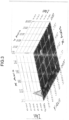
- FIGS. 3 to 5 More specifically, FIG. 3 is a diagram showing a vibration signal occurring in the case of climbing a fence in this Example.
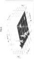
- FIG. 4 is a diagram showing a vibration signal occurring in the case of striking a fence in this Example.
- FIG. 5 is a diagram showing a vibration signal occurring in the case of intersecting an optical fiber in this Example.
- the X axis represents a location on the optical fiber
- the Y axis represents a vibration frequency
- the Z axis represents a vibration intensity.
- the generated decide tree was applied to the area security system, and numerous detection tests were conducted. The results are shown below.
- the wrong detections included 6 detections as fence striking action and 15 detections as optical fiber intersecting action.
- the wrong detections included 3 detections as fence climbing action and 10 detections as optical fiber intersecting action.
- the wrong detections included 26 detections as fence climbing action and 5 detections as fence striking action.
Landscapes
- Engineering & Computer Science (AREA)
- Theoretical Computer Science (AREA)
- Data Mining & Analysis (AREA)
- Physics & Mathematics (AREA)
- General Physics & Mathematics (AREA)
- Evolutionary Computation (AREA)
- Artificial Intelligence (AREA)
- General Engineering & Computer Science (AREA)
- Computer Vision & Pattern Recognition (AREA)
- Life Sciences & Earth Sciences (AREA)
- Bioinformatics & Cheminformatics (AREA)
- Bioinformatics & Computational Biology (AREA)
- Evolutionary Biology (AREA)
- Software Systems (AREA)
- Mathematical Physics (AREA)
- Computing Systems (AREA)
- Medical Informatics (AREA)
- Computational Linguistics (AREA)
- Measurement Of Mechanical Vibrations Or Ultrasonic Waves (AREA)
Description
- The present invention belongs to the field of fiber-optic signal processing, and specifically, relates to a method and a system for detecting and specifying a vibration on the basis of a feature of a fiber-optic signal to determine a time and a spatial location.
- Systems for detecting vibrations by use of a distributed fiber-optic sensor have been employed in the field of facility surveillance, area security, environmental measurement, and the like since they are easy to install, have a wide detection range, and an excellent detection sensitivity. However, a physical property of the distributed fiber-optic sensor causes to be difficult to associate a signal waveform acquired by the distributed fiber-optic sensor with a mechanical vibration received by the distributed fiber-optic sensor by a simple equation. Further, in the case of detecting a vibration by use of the distributed fiber-optic sensor, since there are a variety of interferences and noises in the signal of the distributed fiber-optic sensor, it is difficult to accurately detect and specify a category of the vibration to thereby determine a time and a spatial location of the vibration.
- In conventional vibration detection technique using a distributed fiber-optic sensor, a vibration is detected mainly on the basis of a fluctuation amplitude of a signal of the distributed fiber-optic sensor within a predetermined time window to roughly determine a time and a spatial location. However, the vibration detection technique has not satisfied the daily increasing application demands because it has a high detection error rate, an inferiority in the specification performance of vibrations belonging to different categories, and an inferiority in the determination performance of a time and a spatial location of the vibration.
- Besides, a conventional algorithm detecting and specifying a vibration on the basis of a fiber-optic signal to determine a time and a spatial location detects a fluctuation amplitude of a signal of a distributed fiber-optic sensor mainly on the basis of predetermined time window and frequency range. The algorithm determines the presence or absence of a vibration by comparing a fluctuation amplitude of a signal with a predetermined threshold value. However, since the threshold value is set on the basis of an experience of a measurer, a limitation exists in the distinction of complicated vibrations to categories based on the simple threshold, and it is difficult to maintain a balance between a wrong detection rate and a detection failure rate. Due to the problems described above, there is a limitation in applying the algorithm detecting and specifying a vibration on the basis of a fiber-optic sensor to determine a time and a spatial location to a field which requires high reliability and accuracy.
- As another technique for detecting and specifying a vibration on the basis of a fiber-optic signal, there is a way comprising establishing an equation based on a logical model concerning a relationship between a signal waveform acquired by a distributed fiber-optic sensor and a mechanical vibration received by the distributed fiber-optic sensor, and acquiring a signal feature and a reference threshold value which are necessary to be extracted to detect a vibration. However, a plurality of nonlinear conversions is made in the process from a mechanical vibration to a fiber-optic sensor signal. Therefore, the logical analysis can be applied only to a predetermined simple vibration. Additionally, the logical model uses a large number of approximations, which results in omission of various distortions of the signal feature which occur in an actual process to the fiber-optic sensor signal. Accordingly, the logical model involves large errors, and is disadvantageous in the detection and specification.
- KUN PENG ET AL ("Fiber optic perimeter detection based on principal component analysis", 2016 15TH INTERNATIONAL CONFERENCE ON OPTICAL COMMUNICATIONS AND NETWORKS (ICOCN), IEEE, (20160924), doi:10.1109/ICOCN.2016.7875605, pages 1 - 3) describe a fiber optic perimeter detection system, which screens the event signal by its features in frequency domain and wherein these features are extracted by method of principal component analysis (PCA) and then identified by support vector machine (SVM).
-
JP 2016 091378 A - The claimed invention is defined by the independent claims, while preferred embodiments form the subject of the dependent claims.
- The present invention has been made in view of the above circumstances, and an object thereof is to provide a method and a system for detecting and specifying a vibration on the basis of a feature of a fiber-optic signal to determine a time and a spatial location which can improve an accuracy in detecting and specifying the vibration.
- According to an aspect of the present invention, a method for detecting and specifying a vibration on the basis of a feature of a fiber-optic signal to determine a time and a spatial location comprises the steps of
claim 1. - According to another aspect of the present invention, a system for detecting and specifying a vibration on the basis of a feature of a fiber-optic signal to determine a time and a spatial location comprises the features of claim 3.
- The objects, features, aspects, and advantages of the present invention will be more apparent from the following detailed description and drawings.
-
-
FIG. 1 is a flowchart of a method according to an embodiment of the present invention. -
FIG.2 is a block diagram of a system according to an embodiment of the present invention. -
FIG. 3 is a diagram showing a vibration signal occurring in a case of climbing a fence in an Example. -
FIG. 4 is a diagram showing a vibration signal occurring in a case of striking a fence in the Example. -
FIG. 5 is a diagram showing a vibration signal occurring in a case of intersecting an optical fiber in the Example. - All the terms (including technical terms and scientific terms) recited in the present specification convey the same meanings as what are generally understood by a person skilled in the art unless they are separately defined in the present specification. Further, the terms defined in a dictionary versatilely used convey the same meanings as what are used in the prior art, and should not be interpreted in an idealized meaning or an excessively formal meaning unless they are specifically defined in the present specification.
- The present invention provides a novel algorithm configuration which can solve problems pertaining to conventional algorithms for detecting and specifying a vibration on the basis of a fiber-optic signal to determine a time and a spatial location. The configuration includes a training part and a detecting-specifying part. The training part executes a statistical analysis to initial fiber-optic signals collected through experiments, acquires a feature to detect and specify a vibration, and extracts it as an algorithm parameter. The detecting-specifying part detects a vibration on the basis of the parameter acquired by the training part according to a predetermined signal processing sequence, specifies a category of the vibration, and completes determination of a time and a spatial location of the vibration.
- The algorithm configuration provided according to the present invention is based on a statistical parameter of fiber-optic signal data collected through experiments. This enables the algorithm to accurately treat interferences and/or noises encountered in detecting and specifying a vibration, and also avoid the problem of model error occurring in the method for detecting and specifying a vibration on the basis of a logical model.
- A vibration detected and specified according to the present invention is, for example, an environmental vibration caused by a pedestrian, an automobile, a train, wind, rain, snow, or the like. Further, a field to which the present invention is applied is: for example, excavation prevention, theft prevention, and/or leakage prevention in a petrol/gas pipeline; leakage prevention in a petrol/gas well; water-flow disturbance detection and/or geophysical exploration; intrusion prevention in public facilities such as a train, an airport, and a museum; security protection and security measures in a governmental/national buildings such as a city hall, a prison, and a military base; or intrusion prevention along a border and prevention of illegal border transgression.
- Hereinafter, preferable embodiments of the present invention will be described in detail with reference to the drawings. However, the present invention is not limited to the embodiments.
-
FIG. 1 is a flowchart showing a method according to an embodiment of the present invention. As shown inFIG. 1 , the method includes Step 1 (feature expansion step), Step 2 (dimensionality reduction matrix calculation step), Step 3 (linear dimensionality reduction step), Step 4 (primary classification step), and Step 5 (secondary classification step). - In
Step 1, a feature-expanded function vector is acquired by expanding a feature of initial data of a vibration signal from a distributed fiber-optic sensor. The vibration signal, which is an input data acquired by the distributed fiber-optic sensor, is interpreted as a quadratic function f (t, d) concerning a relationship between a time t and a spatial location d. In this step, the vibration signal f (t, d), which is an input data, is converted into a plurality of feature-expanded functions by a nonlinear conversion. The following functions (1) to (8) can be raised as specific examples of the feature-expanded functions. - (1) Translation of the initial signal with respect to time,
for example,
- (2) Translation of the initial signal with respect to space,
for example,
- (3) Exponent of the initial signal,
for example,
- (4) Component of the initial signal in a frequency band F0,
for example,
- (5) Product of the feature-expanded functions,
for example,
- (6) Product of a feature-expanded function and the initial signal,
for example,
- (7) Partial average values of a time and a spatial location of the initial signal,
- for example,

- where, in the equation, N denotes a maximum value in a time domain, and M denotes a maximum value in a spatial location; and
- for example,
- (8) Partial covariance of the initial signal with respect to space,
for example,
- Among the feature-expanded functions (1) to (8), for example, a nonlinearity can be introduced in the initial data by the function g3 (t, d) or g6 (t, d). On the other hand, for example, data within predetermined time window and space window can be associated with each other by the function g1 (t, d), g2 (t, d), g5 (t, d), g7 (t, d), or g8 (t, d). As a result, the accuracy in detecting and specifying a vibration can be improved. The functions (1) to (8) are nothing more than examples of feature-expanded functions. Further, in
Step 1, a feature-expanded function vector g (t, d) is formed by combining the feature-expanded functions. - In the step subsequent to
Step 1, a calculation of dimensionality reduction matrix is required to reduce the dimensionality of the feature-expanded function vector. Accordingly, in Step 2, the dimensionality reduction matrix W is calculated by executing the statistical analysis to the feature on the basis of the feature-expanded function vector g (t, d). The calculation way is in accordance with Fisher's linear discriminant, which is a linear dimensionality reduction algorithm. Sub-steps 21 to 23 are described below. - First, Kc-number of training sample sets represented by the following equations are collected for each vibration mode c regarding a vibration (including non-vibration) in the category C to be classified. The training sample set is acquired from a value of a feature-expanded function vector g (t, d) representing a relationship between a time t and a spatial location d corresponding to the vibration category c.
- Training Sample Set:

Wherein
- Second, the following statistical amounts are calculated for each vibration category.
- Center of a cluster:

- Variance within the cluster:

- Sum of variances within clusters:

- Center of all the data:

- Variance between clusters:

- Third, the feature values of the matrix represented by the following equation are calculated and decomposed. Subsequently, a feature vector corresponding to Q-number of maximum feature values is acquired. Columns in the dimensionality reduction matrix W are constituted by feature vectors.

- The algorithm is an example for achieving a linear dimensionality reduction matrix. In a method according to an example not forming part of the present invention, the other linear dimensionality reduction algorithms such as Principal Component Analysis (PCA) and Independent Component Analysis (ICA) may be used in place of the aforementioned algorithms.
- In Step 3, the initial data of the vibration signal and the previously acquired feature-expanded functions {f (t, d), g1 (t, d), g2 (t, d), g3 (t, d), ... gP-1 (t, d)} are linearly combined and compressed, and a predetermined number of dimensionality-reduced feature functions {h1 (t, d), h2 (t, d), h3 (t, d), ... hQ (t, d)} is acquired. The dimensionality reduction result can be acquired from a matrix equation represented by the following equation.


- h(t, d) is a function vector of a size Q × 1,

- the dimensionality reduction matrix W is a numerical matrix of a size P × Q,
- the vector h(t, d) has a size smaller than g(t, d), and Q < P.
- In Step 4, the feature vector h (t, d) having been subjected to the dimensionality reduction is input in a classifier (hereinafter, also referred to as "primary classifier") which has been subjected to the training and contains a control parameter, and a vibration category c is output. The value of the vibration category c may be set as c = 1, 2, ..., C, and the category c = 1 means no vibration. A decision tree classifier may be used as the classifier. However, a classifier containing a neural network or a support vector machine (SVM) may be used. Since a variety of trainers are described in the machine learning theory, no further description is made here. The control parameter of the classifier is acquired through the training. In the training of parameter, a training sample set {(h1, c1), (h2, c2), (h3, c3), ...} of the vibration in category C to be classified is input. Here, (hk, ck) represents a training sample in a vibration category ck, and hk denotes a value in a feature function vector h (t, d) which corresponds to an occurrence time t and a spatial location d of the vibration in the current category and has been subjected to the dimensionality reduction. The specific algorithm configuration corresponds to the primary classifier, for example, a decide tree trainer, a neural network trainer, and a support vector machine trainer.
- Step 4 is performed to achieve the primary classification. An error which is contained in the output in Step 4 is removed in the secondary classification in the subsequent Step.
- In Step 5, the primary classification result e (t, d) acquired in Step 4 is improved. The improvement includes removal of a wrongly detected vibration and/or correction of a wrongly classified vibration. In an actual processing, the vibration continuing time and/or the concerning spatial area is large depending on a category difference, and liable to exceed the area covered by the feature-expanded function. Therefore, it is required to execute a secondary analysis by use of a classification result in a broader time and spatial ranges from a higher dimensionality. Sub-steps 51 to 53 are described below.
- First, the primary classification result e (t, d) acquired in Step 4 is converted into a logical variable represented by the following equation. The logical variable is a single sequence variable consisting of the values of 0 and 1.
- Logical variable:

- Wherein

- Second, a score is calculated for each vibration category on the basis of a logical rule in a logical rule base.
- Here, each logical rule includes the following definitions (a) and (b).
- (a) A logical equation is represented by Jb (L), wherein the input L is the entirety of the logical variable

- (b) When the logical equation Jb (L) is established, a contribution degree to a score of each vibration category is


- With respect to B-number of whole logical equations {J1 (L), J2 (L), ..., JB (L)}, a score s (c) when the current vibration signal belongs to category c is calculated in the equation s (c) =

- Third, the vibration category corresponding to a highest score represented by the following equation is output.


- J1 (L) represents a logical event when a vibration in
category 1 is detected by the first classifier at a current time, a preceding time or a time preceding the preceding time. - J2 (L) represents a logical event when a vibration in category 5 is detected by the first classifier at a current location and adjacent locations in front of and behind the current location.
-
FIG.2 is a block diagram (a schematic diagram of a function module) of a system according to an embodiment of the present invention. The system corresponds to the method described in the embodiment. - The system further comprises a parameter database. The parameter database can be used to accumulate at least one of the dimensionality reduction matrix, a classifier parameter, and a logical rule base.
- As described above, one aspect of the present invention is directed to a computer-implemented method for detecting and specifying vibrations on the basis of a feature of a fiber-optic signal to determine a time and a spatial location comprising: Step 1 (feature expansion step) of acquiring a feature-expanded function vector and C-number of vibration categories by expanding a feature of initial data of a vibration signal from a distributed fiber-optic sensor; Step 2 (dimensionality reduction matrix calculation step) of calculating a dimensionality reduction matrix based on the feature-expanded function vector; Step 3 (linear dimensionality reduction step) of acquiring a dimensionality-reduced feature function by operating the dimensionality reduction matrix to the initial data and the feature-expanded function vector; Step 4 (primary classification step) of acquiring a primary classification result of the vibration signal by performing a classification based on the dimensionality-reduced feature function and with reference to a primary classification parameter acquired from a parameter database; and Step 5 (secondary classification step) of acquiring and outputting a secondary classification result of the vibration signal by performing removal of a wrong detection result and correction of a wrong classification result of the primary classification result.
- In the method described above, Step 2 includes: Sub-step 21 of collecting a training sample set represented by the following
Equation 1 for vibration category c; Sub-step 22 of calculating, for each vibration category, a center of a cluster represented by the following Equation 2, a variance within the cluster represented by the following Equation 3, a sum of variances within clusters represented by the following Equation 4, a center of all the data represented by the following Equation 5, and a variance between clusters represented by the following Equation 6; and Sub-step 23 of calculating a feature value of a matrix represented by the followingEquation 7, decomposing the matrix, acquiring Q-number of maximum feature values and corresponding feature vectors, and composing the dimensionality reduction matrix by using columns of the feature vectors. - Training sample set:

- In
Equation 1,
- Center of a cluster:

- In Equation 2, Kc denotes the number of training samples in the category c.
- Variance within a cluster:

- Sum of variances within clusters:

- In Equation 4, C denotes the total number of vibration categories.
- Center of all the data:

- Variance between clusters:


- In an embodiment, Step 5 includes: Sub-step 51 of converting the primary classification result represented by the following Equation 8 to a logical variable represented by the following Equation 9; Sub-step 52 of calculating, for each vibration category, a score of B-number of whole logical equations {J1 (L), J2 (L), ..., JB (L)} in a logical rule base on the basis of a calculation equation represented by the following Equation 10; and Sub-step 53 of outputting a vibration category corresponding to a highest score represented by the following Equation 11 as an output of a secondary classifier.
- Primary Classification Result:

- Logical Variable:

- In Equation 9,

- Calculation Equation:

- In Equation 10, s(c) denotes a score on the basis of the whole logical equations in the logical rule base when the current vibration belongs to category c, wherein the input L in Jb (L) configures all the logical variables


- Another aspect of the present invention is directed to a system for detecting and specifying a vibration on the basis of a feature of a fiber-optic signal to determine a time and a spatial location comprising the features of claim 3.
- In the system, the parameter database is preferably used to accumulate at least one of the dimensionality reduction matrix, a classifier parameter, and a logical rule base.
- The present invention has the following technical advantageous effects.
- The present invention introduces a nonlinearity in the initial data by nonlinearly expanding a feature in the time, space, and frequency band, and associates data within predetermined time window and space window with each other. Consequently, a vibration signal in a single field of time and space is not analyzed as a single point by a classifier, but is analyzed and classified in combination in the subsequent processing. As a result, the feature expansion improves the accuracy in detecting a vibration in the present invention.
- Besides, the present invention adopts a two-stage specification way in specifying a vibration category. In the first stage, a primary classification of a vibration category is performed by use of an expanded feature data. In the second stage, the result of the primary classification is improved in accordance with a logical rule. Specifically, vibration detection results within relatively broad time and spatial ranges are associated with each other in accordance with a predetermined logical rule to thereby eliminate a specification error caused by an occasional interference and a wrong specification. This improves the accuracy in specifying a vibration in the present invention.
- Further, in the present invention, statistical classification technologies and classification experiences in the field of fiber-optic signal detection are effectively combined in the two-stage specification-classification way. This secures the accuracy of a specification algorithm in the present invention.
- According to the present invention, for example, when detecting and specifying an environmental vibration on a railroad by use of a four-tiered decision tree classifier, the high reliability and accuracy were made that the space specification rate was ± 10m; the response time to a vibration was three seconds or less; the wrong detection in a week occurred one or less a day; and the detection failure in a week occurred zero. In contrast, when detecting and specifying an environmental vibration on a railroad by an artificial intelligence (Al), the poor reliability and accuracy were made that the wrong detection in a week occurred twelve or more a day. As it can be seen, the present invention can relatively promptly and also accurately detect and specify a vibration and determine a time and a spatial location in a smaller amount of training data than AI.
- Hereinafter, the present invention will be further specifically described by way of Examples. However, the scope of the present invention is not limited to the Examples, but by the appended claims.
- The present invention was applied to an area security system to distinguish vibrations caused by three types of intrusive actions (namely, fence climbing, fence striking, and optical fiber intersection) defined in the area security system. Detection signals in the three types of invasive actions are shown in
FIGS. 3 to 5 . More specifically,FIG. 3 is a diagram showing a vibration signal occurring in the case of climbing a fence in this Example.FIG. 4 is a diagram showing a vibration signal occurring in the case of striking a fence in this Example.FIG. 5 is a diagram showing a vibration signal occurring in the case of intersecting an optical fiber in this Example. In these drawings, the X axis represents a location on the optical fiber, the Y axis represents a vibration frequency, and the Z axis represents a vibration intensity. - As shown in
FIGS. 3 to 5 , quite remarkable differences were observed between feature vectors corresponding to motions of the different intrusive actions. Specifically, in the case of climbing a fence, the energy distribution is mainly concentrated in a low frequency band in the frequency range. However, in the case of striking a fence, the energy distribution is relatively shifted to a high frequency side compared with the case of climbing the fence. Additionally, in the case of intersecting an optical fiber, the energy distribution is mainly in a high frequency band. The feature vectors corresponding to the motions of the three types of intrusive actions have the significant differences from one another. Thus, these differences could be seen to be usable as an effective training for a feature vector. - Accordingly, a great number of experiments on the three types of intrusive actions was conducted, and the collected fiber-optic sensing data were used as training data. Specifically, sequentially arrayed 19991 pieces of csv data (100 columns) were collected in a given time, and were composited into a csv file with 19991 rows × 100 columns to thereby obtain an initial feature data file "feature.csv" of the events. Subsequently, a csv file "target.csv" with the same number of rows and columns as the file "feature.csv" was produced. All the data in the file "target.csv" was allotted with "0" at the initial place, and the twelfth channel was used as an experimental event occurrence channel based on experimental records and data comparison. The twelfth column of the file "target.csv" was allotted with event data. Specifically, as an event data, "1" was allotted to the case of climbing a fence, "2" to the case of striking a fence, and "3" to the case of intersecting an optical fiber, respectively. When extracting a result on the basis of the feature, the following feature expansion equations were used.
- F1 = input('C:/work/Fiber/dt_tree/data/feature.csv')
- F2 = F1.time_shift(1)
- F3 = F1.time_shift(2)
- F4 = F1.time_shift(3)
- F5 = F1.time_shift(-2)
- F6 = F1.time_shift(-4)
- F7 = F1.time_shift(-8)
- F8 = F1.channel_shift(4)
- F9 = F1.channel_shift(5)
- F10= F1.channel_shift(6)
- F11= F1.channel_shift(-1)
- F12= F1.channel_shift(-2)
- F13= F1.channel_shift(-3)
- After having executed the algorithm program, the generated decide tree was applied to the area security system, and numerous detection tests were conducted. The results are shown below.
- First, in detection test of 2000 fence climbings, 11 detection failures and 21 wrong detections occurred. The wrong detections included 6 detections as fence striking action and 15 detections as optical fiber intersecting action.
- Next, in detection tests of 2000 fence strikings, 5 detection failures and 13 wrong detections occurred. The wrong detections included 3 detections as fence climbing action and 10 detections as optical fiber intersecting action.
- Further, in detection tests of 2000 optical fiber intersections, 3 detection failures and 31 wrong detections occurred. The wrong detections included 26 detections as fence climbing action and 5 detections as fence striking action.
- The whole error rate is: ((11 + 21) + (5 + 13) + (3 + 31)) / (2000 + 2000 + 2000) × 100 = 1.4%. Consequently, the category classification of the three types of intrusive actions that is required for an area security system was confirmed to be established.
- The present application is based on
Chinese Patent Application No. 201811635297.3 filed on December 29, 2018 - The present invention was suitably and fully described above by means of embodiments in order to express the present invention. However, it should be recognized that a person skilled in the art would be able to easily modify and/or improve the embodiments described above. Accordingly, a modified embodiment or an improved embodiment achieved by the person skilled in the art are construed to be comprehended in the protection scope of Claims as long as the modified embodiment or the improved embodiment do not deviate from the protection scope of Claims.
Claims (4)
- A computer-implemented method for detecting and specifying a vibration on the basis of a feature of a fiber-optic signal to determine a time and a spatial location, comprising:Step 1 of acquiring a feature-expanded function vector and C-number of vibration categories by expanding a feature of initial data of a vibration signal from a distributed fiber-optic sensor;Step 2 of calculating a dimensionality reduction matrix based on the feature-expanded function vector;Step 3 of acquiring a dimensionality-reduced feature function by operating the dimensionality reduction matrix to the initial data and the feature-expanded function vector;Step 4 of acquiring a primary classification result of the vibration signal by performing a classification based on the dimensionality-reduced feature function and with reference to a primary classification parameter acquired from a parameter database; the method beingcharacterized bycomprising Step 5 of acquiring and outputting a secondary classification result of the vibration signal by performing removal of a wrong detection result and correction of a wrong classification result of the primary classification result, and byStep 2 including:Sub-step 21 of collecting a training sample set represented by the following Equation 1 for vibration category c;Sub-step 22 of calculating, for each vibration category, a center of a cluster represented by the following Equation 2, a variance within the cluster represented by the following Equation 3, a sum of variances within clusters represented by the following Equation 4, a center of all the data represented by the following Equation 5, and a variance between clusters represented by the following Equation 6; andSub-step 23 of calculating a feature value of a matrix represented by the following Equation 7, decomposing the matrix, acquiring Q-number of maximum feature values and corresponding feature vectors, and composing the dimensionality reduction matrix by using columns of the feature vectors,Training sample set:

 Center of a cluster:
 Variance within the cluster:
 Sum of variances within clusters:
 Center of all the data:
 Variance between clusters:

- The computer-implemented method for detecting and specifying a vibration on the basis of a feature of a fiber-optic signal to determine a time and a spatial location according to claim 1, whereinStep 5 includes:Sub-step 51 of converting the primary classification result represented by the following Equation 8 to a logical variable represented by the following Equation 9;Sub-step 52 of calculating, for each vibration category, a score of B-number of whole logical equations {J1 (L), J2 (L), ..., JB (L)} in a logical rule base on the basis of a calculation equation represented by the following Equation 10; andSub-step 53 of outputting a vibration category corresponding to a highest score represented by the following Equation 11 as an output of a secondary classifier,Primary Classification Result:
 Logical Variable:
 Calculation Equation:

 Vibration category corresponding to a highest score:
- A system for detecting and specifying a vibration on the basis of a feature of a fiber-optic signal to determine a time and a spatial location, comprising:a parameter database;a feature expansion unit for acquiring a feature-expanded function vector and C-number of vibration categories by expanding a feature of initial data of a vibration signal from a distributed fiber-optic sensor;a dimensionality reduction matrix calculation unit for calculating a dimensionality reduction matrix based on the feature-expanded function vector;a linear dimensionality reduction unit for acquiring a dimensionality-reduced feature function by operating the dimensionality reduction matrix to the initial data and the feature-expanded function vector;a primary classification unit for acquiring a primary classification result of the vibration signal by performing a classification based on the dimensionality-reduced feature function and with reference to a primary classification parameter acquired from the parameter database; and characterized by comprisinga secondary classification unit for acquiring and outputting a secondary classification result of the vibration signal by performing removal of a wrong detection result and correction of a wrong classification result of the primary classification result, and bythe dimensionality reduction matrix calculation unit being configured tocollect a training sample set represented by the following Equation 1 for vibration category c;calculate, for each vibration category, a center of a cluster represented by the following Equation 2, a variance within the cluster represented by the following Equation 3, a sum of variances within clusters represented by the following Equation 4, a center of all the data represented by the following Equation 5, and a variance between clusters represented by the following Equation 6; andcalculate a feature value of a matrix represented by the following Equation 7, decomposing the matrix, acquiring Q-number of maximum feature values and corresponding feature vectors, and composing the dimensionality reduction matrix by using columns of the feature vectors,Training sample set:

 Center of a cluster:
 Variance within the cluster:
 Sum of variances within clusters:
 Center of all the data:
 Variance between clusters:

- The system for detecting and specifying a vibration on the basis of a feature of a fiber-optic signal to determine a time and a spatial location according to claim 3, wherein
the parameter database is used to accumulate at least one of the dimensionality reduction matrix, a classifier parameter, and a logical rule base.
Applications Claiming Priority (2)
| Application Number | Priority Date | Filing Date | Title |
|---|---|---|---|
| CN201811635297 | 2018-12-29 | ||
| PCT/JP2019/050799 WO2020138154A1 (en) | 2018-12-29 | 2019-12-25 | Method and system for specifying time-space, and for detecting and identifying vibration on basis of optical fiber signal feature |
Publications (3)
| Publication Number | Publication Date |
|---|---|
| EP3889561A1 EP3889561A1 (en) | 2021-10-06 |
| EP3889561A4 EP3889561A4 (en) | 2022-01-26 |
| EP3889561B1 true EP3889561B1 (en) | 2023-08-02 |
Family
ID=67076704
Family Applications (1)
| Application Number | Title | Priority Date | Filing Date |
|---|---|---|---|
| EP19905331.5A Active EP3889561B1 (en) | 2018-12-29 | 2019-12-25 | Method and system for detecting and identifying vibration on basis of optical fiber signal feature to determine time-space |
Country Status (5)
| Country | Link |
|---|---|
| US (1) | US11892345B2 (en) |
| EP (1) | EP3889561B1 (en) |
| JP (1) | JP7126722B2 (en) |
| CN (1) | CN109974835B (en) |
| WO (1) | WO2020138154A1 (en) |
Families Citing this family (19)
| Publication number | Priority date | Publication date | Assignee | Title |
|---|---|---|---|---|
| CN114127519A (en) | 2019-07-16 | 2022-03-01 | 日本电气株式会社 | Fiber optic sensing system, fiber optic sensing device and method for detecting degradation of a conduit |
| CN110455399B (en) * | 2019-08-12 | 2020-06-09 | 中冶建筑研究总院有限公司 | Method for carrying out global early warning on building structure vibration by using distributed optical fiber |
| CN112597834B (en) * | 2020-12-11 | 2022-05-17 | 华中科技大学 | A method and device for identifying the load state of a structure surface and measuring the thickness |
| CN113205036A (en) * | 2021-04-28 | 2021-08-03 | 同济大学 | Sensing and positioning method for external invasion vibration source of infrastructure |
| CN114166331A (en) * | 2021-12-03 | 2022-03-11 | 武汉理工光科股份有限公司 | A non-threatening signal identification method, device, electronic device and storage medium |
| WO2023119628A1 (en) * | 2021-12-24 | 2023-06-29 | 日本電信電話株式会社 | Determining device, determining method, and program |
| CN114781494B (en) * | 2022-04-01 | 2024-12-31 | 武汉理工大学 | Wing skin damage identification method based on support vector machine and fiber optic sensing technology |
| CN114998837B (en) * | 2022-06-14 | 2024-07-09 | 中电海康集团有限公司 | Real-time identification method, device, system and medium for intrusion event |
| CN115265750B (en) * | 2022-07-19 | 2024-08-16 | 温州市质量技术检测科学研究院 | Optical fiber distributed acoustic wave sensing system and method |
| CN116094597B (en) * | 2022-11-08 | 2026-08-07 | 南京烽火星空通信发展有限公司 | Recognition method of optical fiber disturbance behavior based on voice multi-feature fusion |
| CN115935236B (en) * | 2022-12-14 | 2026-02-17 | 汕头大学 | Optical fiber vibration event classification method based on dual data amplification and storage medium |
| CN116576956A (en) * | 2023-04-17 | 2023-08-11 | 三峡大学 | Multi-source Vibration Signal Separation Method Based on Distributed Optical Fiber Acoustic Sensing |
| CN117096872B (en) * | 2023-08-30 | 2024-10-01 | 南京工业大学 | A day-ahead optimal dispatching method for an electricity-gas integrated energy system |
| CN117360588B (en) * | 2023-10-24 | 2024-05-24 | 武汉理工大学 | A train identification and positioning method, device and equipment based on grating array |
| CN117496650B (en) * | 2024-01-02 | 2024-03-26 | 浙江省白马湖实验室有限公司 | Distributed optical fiber intrusion early warning method and system based on environment embedding |
| CN117848478B (en) * | 2024-01-04 | 2024-07-12 | 中国新时代科技有限公司 | Underwater defensive optical fiber network detection method, device and storage medium |
| WO2025243412A1 (en) * | 2024-05-22 | 2025-11-27 | Ntt株式会社 | Analysis processing system |
| CN119167057B (en) * | 2024-08-29 | 2025-06-13 | 中国铁路武汉局集团有限公司科学技术研究所 | A method for detecting buried depth of optical cable based on distributed optical fiber sensing technology |
| CN121388401B (en) * | 2025-12-24 | 2026-02-27 | 山东省科学院激光研究所 | Lightweight Fiber Optic Vibration Intrusion Event Detection Method and System for Perimeter Security |
Family Cites Families (12)
| Publication number | Priority date | Publication date | Assignee | Title |
|---|---|---|---|---|
| CN102663032B (en) * | 2012-03-26 | 2014-03-05 | 电子科技大学 | A Pattern Recognition Method for Fiber Bragg Grating Fence Intrusion Events |
| CN103198331B (en) * | 2013-03-25 | 2017-02-08 | 江苏易谱恒科技有限公司 | Multiple spectrogram characteristic amalgamation and recognition method based on analysis of PCA-LDA |
| CN104112072B (en) * | 2014-07-15 | 2017-04-05 | 华侨大学 | Operational modal parameter recognition methods based on the principal component analysis of wavelet threshold denoising |
| JP6419534B2 (en) * | 2014-11-06 | 2018-11-07 | 株式会社東芝 | Diagnostic system, diagnostic method and diagnostic program |
| US10552762B2 (en) | 2015-07-16 | 2020-02-04 | Falkonry Inc. | Machine learning of physical conditions based on abstract relations and sparse labels |
| CN105046279B (en) * | 2015-08-07 | 2018-05-15 | 合肥工业大学 | A kind of analog circuit fault method for classifying modes |
| CN105608823B (en) * | 2016-03-14 | 2020-09-11 | 北京北邮国安技术股份有限公司 | Optical fiber security method and system based on principal component analysis |
| CN105973449B (en) * | 2016-04-15 | 2019-03-12 | 深圳艾瑞斯通技术有限公司 | A kind of optical fiber Recognition of Vibration Sources method, apparatus and system |
| AU2017358065B2 (en) | 2016-11-10 | 2023-02-02 | Fiber Sense Limited | Acoustic method and system for providing digital data |
| CN107425906B (en) * | 2017-07-25 | 2019-09-27 | 电子科技大学 | Distributed optical fiber sensing signal processing method for safety monitoring of underground pipeline network |
| CN108388860B (en) * | 2018-02-12 | 2020-04-28 | 大连理工大学 | A fault diagnosis method for aero-engine rolling bearings based on power entropy spectrum-random forest |
| CN108509850B (en) * | 2018-02-24 | 2022-03-29 | 华南理工大学 | Intrusion signal identification method based on distributed optical fiber system |
-
2019
- 2019-01-24 CN CN201910068735.0A patent/CN109974835B/en active Active
- 2019-12-25 US US17/418,459 patent/US11892345B2/en active Active
- 2019-12-25 EP EP19905331.5A patent/EP3889561B1/en active Active
- 2019-12-25 JP JP2020563341A patent/JP7126722B2/en active Active
- 2019-12-25 WO PCT/JP2019/050799 patent/WO2020138154A1/en not_active Ceased
Also Published As
| Publication number | Publication date |
|---|---|
| US20210396573A1 (en) | 2021-12-23 |
| WO2020138154A1 (en) | 2020-07-02 |
| JPWO2020138154A1 (en) | 2021-11-11 |
| EP3889561A4 (en) | 2022-01-26 |
| US11892345B2 (en) | 2024-02-06 |
| CN109974835B (en) | 2021-06-04 |
| JP7126722B2 (en) | 2022-08-29 |
| EP3889561A1 (en) | 2021-10-06 |
| CN109974835A (en) | 2019-07-05 |
Similar Documents
| Publication | Publication Date | Title |
|---|---|---|
| EP3889561A1 (en) | Method and system for specifying time-space, and for detecting and identifying vibration on basis of optical fiber signal feature | |
| Scarpetta et al. | Automatic classification of seismic signals at Mt. Vesuvius volcano, Italy, using neural networks | |
| Yaghmaei-Sabegh | Detection of pulse-like ground motions based on continues wavelet transform | |
| Del Pezzo et al. | Discrimination of earthquakes and underwater explosions using neural networks | |
| EP3321859B1 (en) | Optical fiber perimeter intrusion signal identification method and device, and perimeter intrusion alarm system | |
| CN108509850B (en) | Intrusion signal identification method based on distributed optical fiber system | |
| Zhu et al. | Thermal strain extraction methodologies for bridge structural condition assessment | |
| Laory et al. | Evaluating two model-free data interpretation methods for measurements that are influenced by temperature | |
| CN105608823B (en) | Optical fiber security method and system based on principal component analysis | |
| Akhouayri et al. | A fuzzy expert system for automatic seismic signal classification | |
| KR102389439B1 (en) | RNN based partial discharge detection apparatus and method in gas-insulated switchgear | |
| CN105893208A (en) | Cloud computing platform system fault prediction method based on hidden semi-Markov models | |
| CN116838955B (en) | A two-stage method for identifying interference along oil and gas pipelines | |
| Ibs-von Seht | Detection and identification of seismic signals recorded at Krakatau volcano (Indonesia) using artificial neural networks | |
| Alsina-Pagès et al. | Anomalous events removal for automated traffic noise maps generation | |
| Gentili et al. | Forecasting strong subsequent earthquakes in California clusters by machine learning | |
| Mogushi | Reduction of transient noise artifacts in gravitational-wave data using deep learning | |
| Cantzos et al. | Identifying long-memory trends in pre-seismic MHz Disturbances through Support Vector Machines | |
| Zambon et al. | Real-time urban traffic noise maps: the influence of Anomalous Noise Events in Milan Pilot area of DYNAMAP | |
| Roveri et al. | ADACTA—Advanced component analysis technique for damage detection | |
| KR101468560B1 (en) | A method of detecting outlier pulses of radar signal based on mahalanobis distance | |
| Van der Laat et al. | OKSP: a novel deep learning automatic event detection pipeline for seismic monitoring in Costa Rica | |
| CN118585875A (en) | Interference identification method and system along oil and gas pipelines based on multi-dimensional feature fusion | |
| Yang et al. | Linear prediction of one-sided autocorrelation sequence for noisy acoustics recognition of excavation equipments | |
| Zheng et al. | A Multimodal Deep Learning Framework for Rapid Real‐Time Earthquake Magnitude Classification: Applications to Earthquake Early Warning |
Legal Events
| Date | Code | Title | Description |
|---|---|---|---|
| STAA | Information on the status of an ep patent application or granted ep patent |
Free format text: STATUS: THE INTERNATIONAL PUBLICATION HAS BEEN MADE |
|
| PUAI | Public reference made under article 153(3) epc to a published international application that has entered the european phase |
Free format text: ORIGINAL CODE: 0009012 |
|
| STAA | Information on the status of an ep patent application or granted ep patent |
Free format text: STATUS: REQUEST FOR EXAMINATION WAS MADE |
|
| 17P | Request for examination filed |
Effective date: 20210628 |
|
| AK | Designated contracting states |
Kind code of ref document: A1 Designated state(s): AL AT BE BG CH CY CZ DE DK EE ES FI FR GB GR HR HU IE IS IT LI LT LU LV MC MK MT NL NO PL PT RO RS SE SI SK SM TR |
|
| A4 | Supplementary search report drawn up and despatched |
Effective date: 20220105 |
|
| RIC1 | Information provided on ipc code assigned before grant |
Ipc: G01H 9/00 20060101AFI20211222BHEP |
|
| DAV | Request for validation of the european patent (deleted) | ||
| DAX | Request for extension of the european patent (deleted) | ||
| STAA | Information on the status of an ep patent application or granted ep patent |
Free format text: STATUS: EXAMINATION IS IN PROGRESS |
|
| 17Q | First examination report despatched |
Effective date: 20221005 |
|
| GRAP | Despatch of communication of intention to grant a patent |
Free format text: ORIGINAL CODE: EPIDOSNIGR1 |
|
| STAA | Information on the status of an ep patent application or granted ep patent |
Free format text: STATUS: GRANT OF PATENT IS INTENDED |
|
| RIC1 | Information provided on ipc code assigned before grant |
Ipc: G06F 18/22 20230101ALI20230207BHEP Ipc: G01H 9/00 20060101AFI20230207BHEP |
|
| INTG | Intention to grant announced |
Effective date: 20230223 |
|
| GRAS | Grant fee paid |
Free format text: ORIGINAL CODE: EPIDOSNIGR3 |
|
| GRAA | (expected) grant |
Free format text: ORIGINAL CODE: 0009210 |
|
| STAA | Information on the status of an ep patent application or granted ep patent |
Free format text: STATUS: THE PATENT HAS BEEN GRANTED |
|
| AK | Designated contracting states |
Kind code of ref document: B1 Designated state(s): AL AT BE BG CH CY CZ DE DK EE ES FI FR GB GR HR HU IE IS IT LI LT LU LV MC MK MT NL NO PL PT RO RS SE SI SK SM TR |
|
| REG | Reference to a national code |
Ref country code: GB Ref legal event code: FG4D |
|
| REG | Reference to a national code |
Ref country code: CH Ref legal event code: EP |
|
| REG | Reference to a national code |
Ref country code: DE Ref legal event code: R096 Ref document number: 602019034314 Country of ref document: DE |
|
| REG | Reference to a national code |
Ref country code: IE Ref legal event code: FG4D |
|
| REG | Reference to a national code |
Ref country code: LT Ref legal event code: MG9D |
|
| REG | Reference to a national code |
Ref country code: NL Ref legal event code: MP Effective date: 20230802 |
|
| REG | Reference to a national code |
Ref country code: AT Ref legal event code: MK05 Ref document number: 1595283 Country of ref document: AT Kind code of ref document: T Effective date: 20230802 |
|
| PG25 | Lapsed in a contracting state [announced via postgrant information from national office to epo] |
Ref country code: GR Free format text: LAPSE BECAUSE OF FAILURE TO SUBMIT A TRANSLATION OF THE DESCRIPTION OR TO PAY THE FEE WITHIN THE PRESCRIBED TIME-LIMIT Effective date: 20231103 |
|
| PG25 | Lapsed in a contracting state [announced via postgrant information from national office to epo] |
Ref country code: IS Free format text: LAPSE BECAUSE OF FAILURE TO SUBMIT A TRANSLATION OF THE DESCRIPTION OR TO PAY THE FEE WITHIN THE PRESCRIBED TIME-LIMIT Effective date: 20231202 |
|
| PG25 | Lapsed in a contracting state [announced via postgrant information from national office to epo] |
Ref country code: SE Free format text: LAPSE BECAUSE OF FAILURE TO SUBMIT A TRANSLATION OF THE DESCRIPTION OR TO PAY THE FEE WITHIN THE PRESCRIBED TIME-LIMIT Effective date: 20230802 Ref country code: RS Free format text: LAPSE BECAUSE OF FAILURE TO SUBMIT A TRANSLATION OF THE DESCRIPTION OR TO PAY THE FEE WITHIN THE PRESCRIBED TIME-LIMIT Effective date: 20230802 Ref country code: PT Free format text: LAPSE BECAUSE OF FAILURE TO SUBMIT A TRANSLATION OF THE DESCRIPTION OR TO PAY THE FEE WITHIN THE PRESCRIBED TIME-LIMIT Effective date: 20231204 Ref country code: NO Free format text: LAPSE BECAUSE OF FAILURE TO SUBMIT A TRANSLATION OF THE DESCRIPTION OR TO PAY THE FEE WITHIN THE PRESCRIBED TIME-LIMIT Effective date: 20231102 Ref country code: NL Free format text: LAPSE BECAUSE OF FAILURE TO SUBMIT A TRANSLATION OF THE DESCRIPTION OR TO PAY THE FEE WITHIN THE PRESCRIBED TIME-LIMIT Effective date: 20230802 Ref country code: LV Free format text: LAPSE BECAUSE OF FAILURE TO SUBMIT A TRANSLATION OF THE DESCRIPTION OR TO PAY THE FEE WITHIN THE PRESCRIBED TIME-LIMIT Effective date: 20230802 Ref country code: LT Free format text: LAPSE BECAUSE OF FAILURE TO SUBMIT A TRANSLATION OF THE DESCRIPTION OR TO PAY THE FEE WITHIN THE PRESCRIBED TIME-LIMIT Effective date: 20230802 Ref country code: IS Free format text: LAPSE BECAUSE OF FAILURE TO SUBMIT A TRANSLATION OF THE DESCRIPTION OR TO PAY THE FEE WITHIN THE PRESCRIBED TIME-LIMIT Effective date: 20231202 Ref country code: HR Free format text: LAPSE BECAUSE OF FAILURE TO SUBMIT A TRANSLATION OF THE DESCRIPTION OR TO PAY THE FEE WITHIN THE PRESCRIBED TIME-LIMIT Effective date: 20230802 Ref country code: GR Free format text: LAPSE BECAUSE OF FAILURE TO SUBMIT A TRANSLATION OF THE DESCRIPTION OR TO PAY THE FEE WITHIN THE PRESCRIBED TIME-LIMIT Effective date: 20231103 Ref country code: FI Free format text: LAPSE BECAUSE OF FAILURE TO SUBMIT A TRANSLATION OF THE DESCRIPTION OR TO PAY THE FEE WITHIN THE PRESCRIBED TIME-LIMIT Effective date: 20230802 Ref country code: AT Free format text: LAPSE BECAUSE OF FAILURE TO SUBMIT A TRANSLATION OF THE DESCRIPTION OR TO PAY THE FEE WITHIN THE PRESCRIBED TIME-LIMIT Effective date: 20230802 |
|
| PG25 | Lapsed in a contracting state [announced via postgrant information from national office to epo] |
Ref country code: PL Free format text: LAPSE BECAUSE OF FAILURE TO SUBMIT A TRANSLATION OF THE DESCRIPTION OR TO PAY THE FEE WITHIN THE PRESCRIBED TIME-LIMIT Effective date: 20230802 |
|
| PG25 | Lapsed in a contracting state [announced via postgrant information from national office to epo] |
Ref country code: ES Free format text: LAPSE BECAUSE OF FAILURE TO SUBMIT A TRANSLATION OF THE DESCRIPTION OR TO PAY THE FEE WITHIN THE PRESCRIBED TIME-LIMIT Effective date: 20230802 |
|
| PG25 | Lapsed in a contracting state [announced via postgrant information from national office to epo] |
Ref country code: SM Free format text: LAPSE BECAUSE OF FAILURE TO SUBMIT A TRANSLATION OF THE DESCRIPTION OR TO PAY THE FEE WITHIN THE PRESCRIBED TIME-LIMIT Effective date: 20230802 Ref country code: RO Free format text: LAPSE BECAUSE OF FAILURE TO SUBMIT A TRANSLATION OF THE DESCRIPTION OR TO PAY THE FEE WITHIN THE PRESCRIBED TIME-LIMIT Effective date: 20230802 Ref country code: ES Free format text: LAPSE BECAUSE OF FAILURE TO SUBMIT A TRANSLATION OF THE DESCRIPTION OR TO PAY THE FEE WITHIN THE PRESCRIBED TIME-LIMIT Effective date: 20230802 Ref country code: EE Free format text: LAPSE BECAUSE OF FAILURE TO SUBMIT A TRANSLATION OF THE DESCRIPTION OR TO PAY THE FEE WITHIN THE PRESCRIBED TIME-LIMIT Effective date: 20230802 Ref country code: DK Free format text: LAPSE BECAUSE OF FAILURE TO SUBMIT A TRANSLATION OF THE DESCRIPTION OR TO PAY THE FEE WITHIN THE PRESCRIBED TIME-LIMIT Effective date: 20230802 Ref country code: CZ Free format text: LAPSE BECAUSE OF FAILURE TO SUBMIT A TRANSLATION OF THE DESCRIPTION OR TO PAY THE FEE WITHIN THE PRESCRIBED TIME-LIMIT Effective date: 20230802 Ref country code: SK Free format text: LAPSE BECAUSE OF FAILURE TO SUBMIT A TRANSLATION OF THE DESCRIPTION OR TO PAY THE FEE WITHIN THE PRESCRIBED TIME-LIMIT Effective date: 20230802 |
|
| REG | Reference to a national code |
Ref country code: DE Ref legal event code: R097 Ref document number: 602019034314 Country of ref document: DE |
|
| PG25 | Lapsed in a contracting state [announced via postgrant information from national office to epo] |
Ref country code: IT Free format text: LAPSE BECAUSE OF FAILURE TO SUBMIT A TRANSLATION OF THE DESCRIPTION OR TO PAY THE FEE WITHIN THE PRESCRIBED TIME-LIMIT Effective date: 20230802 |
|
| PLBE | No opposition filed within time limit |
Free format text: ORIGINAL CODE: 0009261 |
|
| STAA | Information on the status of an ep patent application or granted ep patent |
Free format text: STATUS: NO OPPOSITION FILED WITHIN TIME LIMIT |
|
| 26N | No opposition filed |
Effective date: 20240503 |
|
| PG25 | Lapsed in a contracting state [announced via postgrant information from national office to epo] |
Ref country code: SI Free format text: LAPSE BECAUSE OF FAILURE TO SUBMIT A TRANSLATION OF THE DESCRIPTION OR TO PAY THE FEE WITHIN THE PRESCRIBED TIME-LIMIT Effective date: 20230802 |
|
| REG | Reference to a national code |
Ref country code: CH Ref legal event code: PL |
|
| PG25 | Lapsed in a contracting state [announced via postgrant information from national office to epo] |
Ref country code: LU Free format text: LAPSE BECAUSE OF NON-PAYMENT OF DUE FEES Effective date: 20231225 |
|
| PG25 | Lapsed in a contracting state [announced via postgrant information from national office to epo] |
Ref country code: MC Free format text: LAPSE BECAUSE OF FAILURE TO SUBMIT A TRANSLATION OF THE DESCRIPTION OR TO PAY THE FEE WITHIN THE PRESCRIBED TIME-LIMIT Effective date: 20230802 |
|
| REG | Reference to a national code |
Ref country code: BE Ref legal event code: MM Effective date: 20231231 |
|
| PG25 | Lapsed in a contracting state [announced via postgrant information from national office to epo] |
Ref country code: MC Free format text: LAPSE BECAUSE OF FAILURE TO SUBMIT A TRANSLATION OF THE DESCRIPTION OR TO PAY THE FEE WITHIN THE PRESCRIBED TIME-LIMIT Effective date: 20230802 Ref country code: LU Free format text: LAPSE BECAUSE OF NON-PAYMENT OF DUE FEES Effective date: 20231225 |
|
| REG | Reference to a national code |
Ref country code: IE Ref legal event code: MM4A |
|
| PG25 | Lapsed in a contracting state [announced via postgrant information from national office to epo] |
Ref country code: IE Free format text: LAPSE BECAUSE OF NON-PAYMENT OF DUE FEES Effective date: 20231225 |
|
| PG25 | Lapsed in a contracting state [announced via postgrant information from national office to epo] |
Ref country code: BE Free format text: LAPSE BECAUSE OF NON-PAYMENT OF DUE FEES Effective date: 20231231 |
|
| PG25 | Lapsed in a contracting state [announced via postgrant information from national office to epo] |
Ref country code: CH Free format text: LAPSE BECAUSE OF NON-PAYMENT OF DUE FEES Effective date: 20231231 |
|
| PG25 | Lapsed in a contracting state [announced via postgrant information from national office to epo] |
Ref country code: IE Free format text: LAPSE BECAUSE OF NON-PAYMENT OF DUE FEES Effective date: 20231225 Ref country code: CH Free format text: LAPSE BECAUSE OF NON-PAYMENT OF DUE FEES Effective date: 20231231 Ref country code: BE Free format text: LAPSE BECAUSE OF NON-PAYMENT OF DUE FEES Effective date: 20231231 |
|
| PG25 | Lapsed in a contracting state [announced via postgrant information from national office to epo] |
Ref country code: BG Free format text: LAPSE BECAUSE OF FAILURE TO SUBMIT A TRANSLATION OF THE DESCRIPTION OR TO PAY THE FEE WITHIN THE PRESCRIBED TIME-LIMIT Effective date: 20230802 |
|
| PG25 | Lapsed in a contracting state [announced via postgrant information from national office to epo] |
Ref country code: BG Free format text: LAPSE BECAUSE OF FAILURE TO SUBMIT A TRANSLATION OF THE DESCRIPTION OR TO PAY THE FEE WITHIN THE PRESCRIBED TIME-LIMIT Effective date: 20230802 |
|
| PG25 | Lapsed in a contracting state [announced via postgrant information from national office to epo] |
Ref country code: CY Free format text: LAPSE BECAUSE OF FAILURE TO SUBMIT A TRANSLATION OF THE DESCRIPTION OR TO PAY THE FEE WITHIN THE PRESCRIBED TIME-LIMIT; INVALID AB INITIO Effective date: 20191225 |
|
| PG25 | Lapsed in a contracting state [announced via postgrant information from national office to epo] |
Ref country code: HU Free format text: LAPSE BECAUSE OF FAILURE TO SUBMIT A TRANSLATION OF THE DESCRIPTION OR TO PAY THE FEE WITHIN THE PRESCRIBED TIME-LIMIT; INVALID AB INITIO Effective date: 20191225 |
|
| PG25 | Lapsed in a contracting state [announced via postgrant information from national office to epo] |
Ref country code: TR Free format text: LAPSE BECAUSE OF FAILURE TO SUBMIT A TRANSLATION OF THE DESCRIPTION OR TO PAY THE FEE WITHIN THE PRESCRIBED TIME-LIMIT Effective date: 20230802 |
|
| PGFP | Annual fee paid to national office [announced via postgrant information from national office to epo] |
Ref country code: GB Payment date: 20251223 Year of fee payment: 7 |
|
| PGFP | Annual fee paid to national office [announced via postgrant information from national office to epo] |
Ref country code: FR Payment date: 20251223 Year of fee payment: 7 |
|
| PGFP | Annual fee paid to national office [announced via postgrant information from national office to epo] |
Ref country code: DE Payment date: 20251223 Year of fee payment: 7 |