EP3889483A1 - Motorised valve with vertical shaft and super capacitor backup power - Google Patents
Motorised valve with vertical shaft and super capacitor backup power Download PDFInfo
- Publication number
- EP3889483A1 EP3889483A1 EP21154628.8A EP21154628A EP3889483A1 EP 3889483 A1 EP3889483 A1 EP 3889483A1 EP 21154628 A EP21154628 A EP 21154628A EP 3889483 A1 EP3889483 A1 EP 3889483A1
- Authority
- EP
- European Patent Office
- Prior art keywords
- shaft
- valve assembly
- emitter
- sensor
- valve
- Prior art date
- Legal status (The legal status is an assumption and is not a legal conclusion. Google has not performed a legal analysis and makes no representation as to the accuracy of the status listed.)
- Granted
Links
Images




Classifications
-
- F—MECHANICAL ENGINEERING; LIGHTING; HEATING; WEAPONS; BLASTING
- F16—ENGINEERING ELEMENTS AND UNITS; GENERAL MEASURES FOR PRODUCING AND MAINTAINING EFFECTIVE FUNCTIONING OF MACHINES OR INSTALLATIONS; THERMAL INSULATION IN GENERAL
- F16K—VALVES; TAPS; COCKS; ACTUATING-FLOATS; DEVICES FOR VENTING OR AERATING
- F16K37/00—Special means in or on valves or other cut-off apparatus for indicating or recording operation thereof, or for enabling an alarm to be given
- F16K37/0058—Optical means, e.g. light transmission, observation ports
-
- F—MECHANICAL ENGINEERING; LIGHTING; HEATING; WEAPONS; BLASTING
- F16—ENGINEERING ELEMENTS AND UNITS; GENERAL MEASURES FOR PRODUCING AND MAINTAINING EFFECTIVE FUNCTIONING OF MACHINES OR INSTALLATIONS; THERMAL INSULATION IN GENERAL
- F16K—VALVES; TAPS; COCKS; ACTUATING-FLOATS; DEVICES FOR VENTING OR AERATING
- F16K11/00—Multiple-way valves, e.g. mixing valves; Pipe fittings incorporating such valves
- F16K11/02—Multiple-way valves, e.g. mixing valves; Pipe fittings incorporating such valves with all movable sealing faces moving as one unit
- F16K11/06—Multiple-way valves, e.g. mixing valves; Pipe fittings incorporating such valves with all movable sealing faces moving as one unit comprising only sliding valves, i.e. sliding closure elements
- F16K11/065—Multiple-way valves, e.g. mixing valves; Pipe fittings incorporating such valves with all movable sealing faces moving as one unit comprising only sliding valves, i.e. sliding closure elements with linearly sliding closure members
-
- F—MECHANICAL ENGINEERING; LIGHTING; HEATING; WEAPONS; BLASTING
- F16—ENGINEERING ELEMENTS AND UNITS; GENERAL MEASURES FOR PRODUCING AND MAINTAINING EFFECTIVE FUNCTIONING OF MACHINES OR INSTALLATIONS; THERMAL INSULATION IN GENERAL
- F16K—VALVES; TAPS; COCKS; ACTUATING-FLOATS; DEVICES FOR VENTING OR AERATING
- F16K31/00—Actuating devices; Operating means; Releasing devices
- F16K31/02—Actuating devices; Operating means; Releasing devices electric; magnetic
- F16K31/06—Actuating devices; Operating means; Releasing devices electric; magnetic using a magnet, e.g. diaphragm valves, cutting off by means of a liquid
- F16K31/0675—Electromagnet aspects, e.g. electric supply therefor
-
- F—MECHANICAL ENGINEERING; LIGHTING; HEATING; WEAPONS; BLASTING
- F16—ENGINEERING ELEMENTS AND UNITS; GENERAL MEASURES FOR PRODUCING AND MAINTAINING EFFECTIVE FUNCTIONING OF MACHINES OR INSTALLATIONS; THERMAL INSULATION IN GENERAL
- F16K—VALVES; TAPS; COCKS; ACTUATING-FLOATS; DEVICES FOR VENTING OR AERATING
- F16K37/00—Special means in or on valves or other cut-off apparatus for indicating or recording operation thereof, or for enabling an alarm to be given
- F16K37/0025—Electrical or magnetic means
- F16K37/0041—Electrical or magnetic means for measuring valve parameters
Definitions
- a valve assembly comprising a shaft, the shaft comprising a sight through-hole and a flow through-hole.
- the valve assembly further comprises a shaft position mechanism which comprises a driving means configured to provide movement to the shaft and at least one emitter with at least one corresponding sensor.
- the valve assembly further comprises at least one flow path from at least one fluid inlet to at least one fluid outlet.
- the shaft is configured to move across the at least one flow path so as to allow flow therethrough in a first position, and to block the at least one flow path in a second position.
- a vertical shaft 10 for use in a motorised valve is shown in figure 1 .
- the shaft extends from a first longitudinal end 14, along a central longitudinal axis, to a second, opposite longitudinal end 15.
- the shaft comprises means 11 configured to provide movement of the shaft, which in this example are grooves 11. Other means may alternatively/also be used.
- the grooves may be formed via different methods. In this example the grooves are formed by milling.
- the shaft may be configured to move axially in the direction of the second end 15. In figure 1 , the movement of the shaft 10 is in the vertical axial direction as shown in figure 1 .
- valve 30 may comprise any number of inlets, outlets, and the shaft may comprise a corresponding number of flow through-holes. Additionally the shaft may be provided with more diode/sensor pairs, and/or a corresponding number of sight through-holes. In this way, it is envisaged that the valve may be a comparatively more complicated valve with more ports, and multilevel shafts.
- Supercapacitor block 526 harvests the power from the main power line 513 via main voltage regulator 524 after the start of the power on system, to charge the supercapacitor 31 to store backup power.
- the valve harvests supply power to charge the capacitor, and thereby, if there is a lack of power being supplied to the valve, the energy from the supercapacitor energy is used to power the limited voltage regulator. In such a case, even though the valve is not able to move the shaft, the system can still be informed of the position of the shaft, just as in a corresponding microswitch position sensor.
Landscapes
- Engineering & Computer Science (AREA)
- General Engineering & Computer Science (AREA)
- Mechanical Engineering (AREA)
- Physics & Mathematics (AREA)
- Electromagnetism (AREA)
- Indication Of The Valve Opening Or Closing Status (AREA)
Abstract
Description
- Motorised valves can indicate position of a valve shaft via the use of microswitches. These can give information about a position of a valve shaft even if the valve is not being sourced with power, as they provide a physical position input. However, other sensors cannot provide such functionality, and rather require constant power to feedback the position of the valve. Therefore, if it is necessary that the position of the valve is still to be measured in the event of a power failure, it is not possible to use other sensors such as optical sensors.
- For example, such motorised valves may be provided within aircraft.
- In a first aspect, there is provided a valve assembly comprising a shaft, the shaft comprising a sight through-hole and a flow through-hole. The valve assembly further comprises a shaft position mechanism which comprises a driving means configured to provide movement to the shaft and at least one emitter with at least one corresponding sensor. The valve assembly further comprises at least one flow path from at least one fluid inlet to at least one fluid outlet. The shaft is configured to move across the at least one flow path so as to allow flow therethrough in a first position, and to block the at least one flow path in a second position. The at least one emitter and the at least one corresponding sensor are positioned such that, when the shaft is in the first position, the sensor can sense the emitter through the sight through-hole of the shaft, and when the shaft is in the second position, the sensor is blocked from the emitter by the shaft.
- Additionally, the at least one emitter may comprise a first and a second emitter, and the at least one corresponding sensor may comprise corresponding first and second sensors, and the at least one fluid outlet may comprise a first and a second fluid outlet. The shaft may be further configured to move to a third position so as to allow flow from the at least one inlet to the first outlet, and block flow from the at least one inlet to the second outlet. The first and second emitter and the corresponding first and second sensors may be positioned such that, when the shaft is in the first position, the first sensor can sense the first emitter through the sight through-hole of the shaft, and the second sensor is blocked from the second emitter by the shaft; and when the shaft is in the second position, the first and second sensors are blocked from the first and second emitter by the shaft, and when the shaft is in the third position, the second sensor can sense the second emitter through the sight through-hole of the shaft, and the first sensor is blocked from the first emitter by the shaft.
- The fluid inlets and outlets may be located within a bracket, and wherein the valve assembly is provided with a cylindrical cover with a threaded connection to connect to the bracket. The assembly may further comprise o-rings to seal the valve assembly.
- The at least one emitter may be diodes.
- The valve assembly may further comprise power and signal wires for connection to an external system. The valve assembly may further comprise a direct current, DC, motor to operate the driving means.
- The shaft of the valve assembly may further comprise grooves in the shaft that interact with the driving means to provide movement of the shaft.
- The valve assembly may further comprise, a supercapacitor, the supercapacitor being configured to power at least the at least one emitter and the at least one sensor.
- In a second aspect, there is provided a system comprising the valve assembly as described above, a control module; and a power source, wherein the power source is configured to power the valve assembly and charge the supercapacitor, the supercapacitor being configured to power the at least one emitter and the at least one sensor in case of failure of the power source. For example, the system may be provided for use in an aircraft.
- In the event of a power failure of the power source, the shaft may be configured to move to the second position, thereby closing the valve.
- Preferred examples will now be described by way of example only and with reference to the drawings.
-
Fig. 1 shows a shaft for a motorised valve. -
Fig. 2 shows a shaft position indication mechanism incorporating the shaft offigure 1 . -
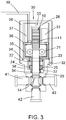
Fig. 3 shows a valve incorporating the shaft position indication mechanism offigure 2 . -
Fig. 4A shows a valve with the shaft in the high position. -
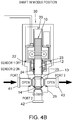
Fig. 4B shows a valve with the shaft in the middle position. -
Fig. 4C shows a valve with the shaft in the low position. -
Fig. 5 shows a schematic block diagram of the control module of a motorised valve. - Microswitch sensors typically used as position sensors in motorised valves suffer from several issues. Firstly, the microswitches themselves can suffer from mechanical wear down after repeated use. For example, the metal lever that is used as a contact in a microswitch can bend, which can render the microswitch ineffective. Microswitches additionally need to be customised so as to interact as desired with the rotary cam to push the microswitch lever according to its position. Additionally, microswitches have a wide tolerance on their operating level, which can lead to imprecise measurements of position.
- In contrast, optical sensors have several benefits when compared to known microswitch sensors. Namely, such optical sensors do not suffer from mechanical wear down, as there need not be any physical contact between the sensors and the item which position is measured. Additionally, such sensors have no loose elements, which means that they are highly tolerant to vibrations. Generic optical sensors may be used as they do not need to directly interact with the valve to measure the position. Additionally, they operate with higher precision. The optical sensor precision can be achieved by providing a high density of light through only small diameters of holes.
- A
vertical shaft 10 for use in a motorised valve is shown infigure 1 . The shaft extends from a firstlongitudinal end 14, along a central longitudinal axis, to a second, opposite longitudinal end 15. The shaft comprises means 11 configured to provide movement of the shaft, which in this example aregrooves 11. Other means may alternatively/also be used. The grooves may be formed via different methods. In this example the grooves are formed by milling. The shaft may be configured to move axially in the direction of the second end 15. Infigure 1 , the movement of theshaft 10 is in the vertical axial direction as shown infigure 1 . Theshaft 10 further comprises a sight through-hole 12, provided on its outer surface that, in use, is positioned so as to align with one ormore sensors more sensors hole 22 may indicate the position of the vertical shaft. Theshaft 10 also comprises a fluid flow through-hole 13, such that, a fluid path may be provided through theshaft 10, before the end of theshaft 14. - In use, the
shaft 10 may form part ofshaft position mechanism 20 within a valve. Theshaft position mechanism 20 is shown infigure 2 . The means for providingmovement 11 is/are provided so as work in combination with a corresponding driving means 21 to provide movement of theshaft 10. In the example offigure 2 , the driving means 20 comprise a set ofgears 21, which are configured to mesh with themilled grooves 11 ofshaft 10. In this way, rotation of thegears 21 provides a corresponding axial movement of theshaft 10. - The
shaft position mechanism 20 may further comprise at least two position sensors comprising emitters and corresponding receivers. For example, as can be seen infigure 2 , themechanism 20 comprises twoinfrared diodes respective sensor emitter respective sensor sensor sensor - For further connection to ports, the
shaft position mechanism 20 may be further provided with abracket 26 for the attachment of inlets and outlets, as well assealings 27 between theshaft 10 and thebracket 26, and between any additional ports. Theshaft position mechanism 20 may further be provided within ahousing 28 so as to separate the shaft mechanism from any additional electronics. - A
valve 30 incorporating theshaft position mechanism 20 is shown infigure 3 . Thevalve 30 has aninlet port 41 andoutlet ports inlet port 41, andoutlet ports housing 28 of the shaft position mechanism separates the shaft mechanism from the other electronics of thevalve 30. - In normal use, the
valve 30 may be powered by a power source connected towires 39. For example, when thevalve 30 is provided in an aircraft,wires 39 may be connected to the internal power network of the airplane to operate thevalve 30. Thewires 39 may comprise both power, and signal wires. - The valve may further comprise a
motor 35 to operate the driving means 21, which in turn cooperates with the means for providingmovement 11 of theshaft 10 to provide vertical movement of theshaft 10 as discussed above. For example, themotor 35 may be a DC motor configured to drive thegears 21 that interact with the milledgrooves 11 to move theshaft 10 vertically past thebracket 26, and towards the flowpath frominlet 41 tooutlets inlet 41 andoutlets - The
valve 30 may further comprise asupercapacitor 31.Supercapacitor 31 may be charged by the power system that otherwise operates thevalve 30 after starting the power system, and may have enough capacity to operate theshaft position mechanism 20, at least such that the position of the valve can be sensed even after power supply is lost. For example, when thevalve 30 is used in an airplane, thesupercapacitor 31 may be charged by the internal power network of the airplane after starting the airplane power. If the power supply fails, then the power provided by thesupercapacitor 31 enables theshaft indication mechanism 20 to still operate, thereby still providing an indication of the position of theshaft 10 within thevalve 30, and therefore the operating status of thevalve 30.Supercapacitor 31 may provide enough power to operate the shaft position mechanism for at least 2 hours, after power has been lost. -
Supercapacitor 31 may be provided so as to be integrally formed with theelectronic module 36, which further connects to thediodes sensors internal signal wires 35. Theelectronics module 36 may further be connected to a power source bywires 39. Thewires 39 may comprise signal wires that allow thevalve 30 to be controlled, as well as power wires to power thevalve 30. In this way, theelectronics module 36 can chargesupercapacitor 31 when thevalve 30 is connected to a functioning power source viawires 39, and power thediodes corresponding sensors electronics module 36 may power thediodes corresponding sensors supercapacitor 31, thereby maintaining the function of the position sensor even during power outages. - Additionally, the
valve 30 may be provided with a cylindrical cover(s) so as to provide quick, easy and reversible connections. For example, thevalve 30 may be provided with acylindrical cover 38 that is assembled together with threadedconnections 32 so as to functionally connect thevalve 30 to theshaft position mechanism 20 and itsbracket 26. Further, these connections may be sealed with O-rings 34, thereby preventing fluid from passing into thevalve 30. In this way, only external power needs to be connected towires 39, through thecylindrical cover 38. - The use of a longitudinal shaft, as opposed to a known rotary ball shaft, simplifies the use of an optical sensor for determining the position of the
shaft 10. - The use of the
valve 30 can be seen infigures 4A to 4C and will now be described. -
Fig. 4A shows thevalve 30 with theshaft 10 in a first, or high position. As can be seen, when theshaft 10 is in this first position, i.e. the high position in this figure, theshaft 10 does not lie within the flow path defined byinlet 41, andoutlets first sensor 22 is activated by light fromdiode 23 passing through the sight through-hole 12of theshaft 10.Sensor 22 therefore provides an "on" signal. However, in this position, asecond sensor 24 is deactivated, because theshaft 10 separates and blocks light from travelling between thediode 25 andsecond sensor 24. This is because no direct line of sight is provided between the diode and sensor in this position.Sensor 24 therefore provides an "off" signal. - In this high position, the
first end 14 ofshaft 10 is provided so as to be positioned above thebracket 26. Therefore fluid may freely flow between theinlet 41 andoutlets -
Fig. 4B shows thevalve 30 with theshaft 10 in a second, i.e. middle position. As can be seen, whenshaft 10 is in this middle position, theshaft 10 is positioned so as to lie within thebracket 26 such that a flow path is defined byinlet 41, through flow through-hole 13 in theshaft 10, and through theoutlet 43. Flow to theoutlet 42 is blocked by thefirst end 14 of theshaft 10. In this position, thefirst sensor 22 is deactivated, because theshaft 10 separates thefirst diode 23 from thefirst sensor 22, and therefore no direct line of sight is provided between thefirst diode 23 and thefirst sensor 22.Sensor 22 therefore provides an "off" signal as not light is able to pass through the sight through-hole 12. However, in this position, thesecond sensor 24 is activated by light fromsecond diode 25 passing through the sight through-hole 12. Thesecond sensor 24 therefore provides an "on" signal in this second position. - In this middle position, fluid may freely flow between
inlet 41 andoutlets 43, but fluid flow cannot pass to and through the outlet, since thefirst end 14 of theshaft 10 blocks flow tooutlet 42. -
Fig. 4C shows the valve with the shaft in a third, i.e. low position. As can be seen, when theshaft 10 is in the low position, theshaft 10 is positioned so that it lies completely within thebracket 26 such that all fluid flow is blocked byshaft 10. In this position, sight through-hole 12 lies above thebracket 26, and flow through-hole 13 lies below thebracket 26. In this position, bothsensors shaft 10separates diodes sensors first sensor 22 therefore provides an "off" signal, and similarlysecond sensor 24 also provides an "off" signal. - In this low position, fluid is blocked by the
shaft 10, and cannot flow frominlet 41 to eitheroutlet 42 oroutlet 43. - As can be seen above, for each of the high, middle and low positions, a unique combination of outputs from
sensors shaft 10, and thereby, through whichoutlets valve 30 may comprise any number of inlets, outlets, and the shaft may comprise a corresponding number of flow through-holes. Additionally the shaft may be provided with more diode/sensor pairs, and/or a corresponding number of sight through-holes. In this way, it is envisaged that the valve may be a comparatively more complicated valve with more ports, and multilevel shafts. - A schematic block diagram of the
control module 36 of the motorised valve is shown infigure 5 . Thecontrol module 36 may be located as seen infigure 3 . Thecontrol module 36 may be located within thevalve 30 connected to aconnector 510, viawires 39 seen infigure 3 and ended withconnector 510.Connector 510 may comprise signal line pins 511, 512, and voltage pins 513. A voltage supply and ground are supplied throughpins 513 to amain voltage regulator 524, which distributes valve power voltage toDC motor 35 viaDC motor driver 535. For the low voltage blocks, limited voltage andcurrent regulator 527 supplies voltage to the low voltage blocks of the control module 500. -
Supercapacitor block 526 harvests the power from themain power line 513 viamain voltage regulator 524 after the start of the power on system, to charge thesupercapacitor 31 to store backup power. - The position of the
shaft 10 is detected by post processing the signals from the sensors insensor block 522 andposition indication block 523. - The logic block 521 (or microcontroller unit (MCU)) interprets the command signals 511, 512 from the
connector 510 and compares them to the actual position of the shaft, and if a change is required,logic block 521 sends a signal to theDC motor driver 521 with an integrated H-Bridge which directly rotates the motor. - During normal operation, the no
power sensor 525 controls the supply of power from the limited voltage andcurrent regulator 527. However, in the case of no power, thesupercapacitor block 526 is used to supply the logic block/MCU,IR sensor block 522 and theposition indication block 523. Thesupercapacitor 31 may provide enough power to continue to provide a shaft position indication for many hours. - In the no power mode, an
alert signal 514 is put onconnector 510, and the position of the shaft is still detected, and the higher operating system is still informed about status of the valve, without the need to use a microswitch position sensor. In order to provide detection of shaft position for a longer period, theDC motor driver 535 may not be provided with enough power to move theDC motor 35. The system may additionally be configured such that the valve may be moved to a safe (e.g. closed) position, as the supercapacitor may store enough power for a limited number of position changes. - In this way, the
valve 30 is able to detect valve position no matter of power line status. In the event of there being no power, the supercapacitor secures the low voltage elements and puts logic signals on the connector pins. Therefore, the present valve with supercapacitor based backup power uses optical sensors instead of microswitches, yet can still indicate the position of the valve even if power to the valve is lost. - The inlet/outlet ports are controlled with vertical shaft, which varies the flow path depending on the vertical position of the shaft. By using such a vertical shaft, a comparatively simple position sensor may be utilised, by providing sight through-holes in the shaft such that diodes and corresponding sensors can be utilised for a simple, and low power position indication.
- Additionally, the valve harvests supply power to charge the capacitor, and thereby, if there is a lack of power being supplied to the valve, the energy from the supercapacitor energy is used to power the limited voltage regulator. In such a case, even though the valve is not able to move the shaft, the system can still be informed of the position of the shaft, just as in a corresponding microswitch position sensor.
- Such a valve therefore allows position indication independent of main power source, as well as a lower power consumption. There is provided a simple assembly design of sensor parts, with limited moving elements, and easier sealing. This results in a low assembly cost, with many possible configurations and a lower weight and various dimensions of valve being possible.
- The provision of a shaft with integrated flow and sight through-holes allows for many different configuration of valves. Further, the sealed arrangement using cylindrical sealed threaded connectors allows for the sensors and electronics to be separated, thereby providing a more robust valve.
Claims (11)
- A valve assembly comprising:a shaft (10), the shaft comprising;a sight through-hole (12); anda flow through-hole (13);the valve assembly further comprising a shaft position mechanism (20), the shaft position mechanism comprising;a driving means (21) configured to provide movement to the shaft;at least one emitter (23, 25) and at least one corresponding sensor (22, 24);the valve assembly further comprising at least one flow path from at least one fluid inlet (41) to at least one fluid outlet (42, 43);wherein the shaft (10) is configured to move across the at least one flow path so as to allow flow therethrough in a first position, and to block the at least one flow path in a second position;wherein the at least one emitter (23, 25) and the at least one corresponding sensor (22, 24) are positioned such that, when the shaft is in the first position, the sensor (22, 24) can sense the emitter (23, 25) through the sight through-hole (12) of the shaft (10), and when the shaft is in the second position, the sensor (22, 24) is blocked from the emitter (23, 25) by the shaft (10).
- The valve assembly of claim 1, wherein the at least one emitter comprises a first and a second emitter (23, 25), and the at least one corresponding sensor comprises corresponding first and second sensors (22, 24), and wherein the at least one fluid outlet comprises a first and a second fluid outlet (42, 43);
wherein the shaft (10) is further configured to move to a third position so as to allow flow from the at least one inlet (41) to the first outlet (42), and block flow from the at least one inlet (41) to the second outlet (43); and
wherein the first and second emitter (23, 25) and the corresponding first and second sensors (22, 24) are positioned such that;when the shaft is in the first position, the first sensor (22) can sense the first emitter (23) through the sight through-hole (12) of the shaft (10), and the second sensor (24) is blocked from the second emitter (25) by the shaft; andwhen the shaft is in the second position, the first and second sensors (22, 24) are blocked from the first and second emitter (23, 25) by the shaft (10); andwhen the shaft is in the third position, the second sensor (24) can sense the second emitter (25) through the sight through-hole (12) of the shaft (10), and the first sensor (22) is blocked from the first emitter (23) by the shaft. - The valve assembly of claim 1 or 2 wherein the fluid inlets and outlets are located within a bracket (26), and wherein the valve assembly is provided with a cylindrical cover (38) with a threaded connection to connect to the bracket (26).
- The valve assembly of claim 3, further comprising o-rings (34) to seal the valve assembly.
- The valve assembly of any preceding claim wherein the at least one emitter (23, 25) are diodes.
- The valve assembly of any preceding claim, further comprising power and signal wires (39) for connection to an external system.
- The valve assembly of any preceding claim, further comprising a direct current, DC, motor (35) to operate the driving means (21).
- The valve assembly of any preceding claim, wherein the shaft (10) further comprises grooves (11) configured to interact with the driving means (21) to provide movement of the shaft (10).
- The valve assembly of any preceding claim, the valve assembly further comprising;
a supercapacitor (31), the supercapacitor (31) being configured to power the at least one emitter (23, 25) and the at least one sensor (23, 24). - A system comprising;the valve assembly of claim 9;a control module (36); anda power source, wherein the power source is configured to power the valve assembly and charge the supercapacitor (31), the supercapacitor (31) being configured to power the at least one emitter (23, 25) and the at least one sensor (23, 24) in case of failure of the power source.
- The system of claim 10, wherein, in the event of a power failure of the power source, the shaft (10) is configured to move to the second position, thereby closing the valve.
Applications Claiming Priority (1)
| Application Number | Priority Date | Filing Date | Title |
|---|---|---|---|
| PL43344820 | 2020-04-03 |
Publications (2)
| Publication Number | Publication Date |
|---|---|
| EP3889483A1 true EP3889483A1 (en) | 2021-10-06 |
| EP3889483B1 EP3889483B1 (en) | 2024-05-29 |
Family
ID=74494844
Family Applications (1)
| Application Number | Title | Priority Date | Filing Date |
|---|---|---|---|
| EP21154628.8A Active EP3889483B1 (en) | 2020-04-03 | 2021-02-01 | Motorised valve with vertical shaft and super capacitor backup power |
Country Status (2)
| Country | Link |
|---|---|
| US (1) | US11499652B2 (en) |
| EP (1) | EP3889483B1 (en) |
Families Citing this family (1)
| Publication number | Priority date | Publication date | Assignee | Title |
|---|---|---|---|---|
| EP4239835A1 (en) | 2022-03-03 | 2023-09-06 | B/E Aerospace, Inc. | Motorised valve backup circuit |
Citations (4)
| Publication number | Priority date | Publication date | Assignee | Title |
|---|---|---|---|---|
| US4099704A (en) * | 1975-12-26 | 1978-07-11 | Hitachi, Ltd. | Vacuum valve apparatus |
| US20110105991A1 (en) * | 2009-10-30 | 2011-05-05 | Codman Neuro Sciences Sarl | Tools and methods for programming an implantable valve |
| US20130255786A1 (en) * | 2010-12-13 | 2013-10-03 | Panasonic Corporation | Flow control valve |
| EP3538800A1 (en) * | 2016-11-08 | 2019-09-18 | Eaton Intelligent Power Limited | Valve assembly and method for controlling a flow of a fluid using a shape memory alloy member |
Family Cites Families (10)
| Publication number | Priority date | Publication date | Assignee | Title |
|---|---|---|---|---|
| US6883614B2 (en) * | 2003-05-02 | 2005-04-26 | Power Chokes | Modular actuator system for valves and chokes |
| US7562859B2 (en) * | 2004-08-20 | 2009-07-21 | Stream-Flo Industries Ltd. | Gate valve with tongue and groove or bridging seal to annular seat elements |
| BRPI0621387B1 (en) | 2006-03-07 | 2018-11-27 | Flowserve Management Company | method for driving valve actuator position encoder and valve actuator system |
| GB2461451B (en) | 2007-03-22 | 2011-12-28 | I2O Water Ltd | Pilot valve for a pressure reducing valve |
| US9518675B2 (en) * | 2013-04-22 | 2016-12-13 | Safoco, Inc. | Rotary stem position indicator |
| EP3115666A1 (en) | 2015-07-08 | 2017-01-11 | Ulefos Esco AS | A smart valve and automated monitoring of the conditions of the pipings using the smart valves |
| US10125892B2 (en) | 2016-06-13 | 2018-11-13 | Thomas Bentz | Solenoid valve device |
| JP6122541B1 (en) * | 2016-11-22 | 2017-04-26 | 伸和コントロールズ株式会社 | Two-way valve for flow control and temperature control device using the same |
| US20210116322A1 (en) * | 2019-10-16 | 2021-04-22 | Everactive, Inc. | Monitoring techniques for pressurized systems |
| US20210131586A1 (en) * | 2019-11-04 | 2021-05-06 | Emerson Process Management Valve Automation, Inc. | Electric Valve Actuator with Energy Harvesting Position Detector Assemblies |
-
2021
- 2021-02-01 EP EP21154628.8A patent/EP3889483B1/en active Active
- 2021-03-25 US US17/212,116 patent/US11499652B2/en active Active
Patent Citations (4)
| Publication number | Priority date | Publication date | Assignee | Title |
|---|---|---|---|---|
| US4099704A (en) * | 1975-12-26 | 1978-07-11 | Hitachi, Ltd. | Vacuum valve apparatus |
| US20110105991A1 (en) * | 2009-10-30 | 2011-05-05 | Codman Neuro Sciences Sarl | Tools and methods for programming an implantable valve |
| US20130255786A1 (en) * | 2010-12-13 | 2013-10-03 | Panasonic Corporation | Flow control valve |
| EP3538800A1 (en) * | 2016-11-08 | 2019-09-18 | Eaton Intelligent Power Limited | Valve assembly and method for controlling a flow of a fluid using a shape memory alloy member |
Also Published As
| Publication number | Publication date |
|---|---|
| US11499652B2 (en) | 2022-11-15 |
| EP3889483B1 (en) | 2024-05-29 |
| US20210310581A1 (en) | 2021-10-07 |
Similar Documents
| Publication | Publication Date | Title |
|---|---|---|
| TWI409398B (en) | Improvements to valve actuators | |
| US4575027A (en) | Electromechanical actuator system with anti-jamming features | |
| US6041857A (en) | Motor drive actuator for downhole flow control devices | |
| EP3889483B1 (en) | Motorised valve with vertical shaft and super capacitor backup power | |
| US10550951B2 (en) | Actuator with brushless DC motor | |
| US20150114151A1 (en) | Electromechanical actuator and actuator unit | |
| KR102536986B1 (en) | Wheel speed sensor having a plurality of sensing units and wheel bearing provided therewith | |
| KR101750738B1 (en) | Actuator and position detection method | |
| KR101740337B1 (en) | Electrical driving ball valve for controlling precise quantity of flow | |
| US8210206B2 (en) | Dual redundant servovalve | |
| CN101151463B (en) | Adjusting device for a hydrostatic piston machine, comprising an electronic control unit | |
| CA2649330A1 (en) | Modular fuel supply device for a gas turbine | |
| US20150086403A1 (en) | Internal-Gear Pump and Hydraulic Circuit for a Motor Vehicle Drivetrain | |
| KR101749134B1 (en) | Electro-mechanical actuator for the aircraft to prevent malfunction | |
| KR101890313B1 (en) | Electro-mechanical actuator for preventing malfunction with external sensor signal | |
| JP2012102883A (en) | Method of detecting displacement of worm shaft | |
| AU597559B2 (en) | Fail-safe potentiometer feedback system | |
| AU729246B2 (en) | Motor drive actuator for downhole flow control devices | |
| KR101989161B1 (en) | Electro-mechanical actuator with multiple sensors to prevent malfunction | |
| US4394999A (en) | Redundant or emergency steering mechanism especially for an aircraft | |
| US6367768B1 (en) | Direct control fuel valve for fuel flow injecting circuit | |
| EP1006284A2 (en) | Control valve system | |
| US20050268975A1 (en) | Valve for a hydraulic power steering | |
| EP4022763B1 (en) | Fault tolerant actuator assembly | |
| BRPI0603144B1 (en) | member to control air flow to an internal combustion engine of a motor vehicle |
Legal Events
| Date | Code | Title | Description |
|---|---|---|---|
| PUAI | Public reference made under article 153(3) epc to a published international application that has entered the european phase |
Free format text: ORIGINAL CODE: 0009012 |
|
| STAA | Information on the status of an ep patent application or granted ep patent |
Free format text: STATUS: THE APPLICATION HAS BEEN PUBLISHED |
|
| AK | Designated contracting states |
Kind code of ref document: A1 Designated state(s): AL AT BE BG CH CY CZ DE DK EE ES FI FR GB GR HR HU IE IS IT LI LT LU LV MC MK MT NL NO PL PT RO RS SE SI SK SM TR |
|
| STAA | Information on the status of an ep patent application or granted ep patent |
Free format text: STATUS: REQUEST FOR EXAMINATION WAS MADE |
|
| 17P | Request for examination filed |
Effective date: 20220406 |
|
| RBV | Designated contracting states (corrected) |
Designated state(s): AL AT BE BG CH CY CZ DE DK EE ES FI FR GB GR HR HU IE IS IT LI LT LU LV MC MK MT NL NO PL PT RO RS SE SI SK SM TR |
|
| GRAP | Despatch of communication of intention to grant a patent |
Free format text: ORIGINAL CODE: EPIDOSNIGR1 |
|
| STAA | Information on the status of an ep patent application or granted ep patent |
Free format text: STATUS: GRANT OF PATENT IS INTENDED |
|
| INTG | Intention to grant announced |
Effective date: 20240104 |
|
| GRAS | Grant fee paid |
Free format text: ORIGINAL CODE: EPIDOSNIGR3 |
|
| GRAA | (expected) grant |
Free format text: ORIGINAL CODE: 0009210 |
|
| STAA | Information on the status of an ep patent application or granted ep patent |
Free format text: STATUS: THE PATENT HAS BEEN GRANTED |
|
| AK | Designated contracting states |
Kind code of ref document: B1 Designated state(s): AL AT BE BG CH CY CZ DE DK EE ES FI FR GB GR HR HU IE IS IT LI LT LU LV MC MK MT NL NO PL PT RO RS SE SI SK SM TR |
|
| REG | Reference to a national code |
Ref country code: CH Ref legal event code: EP |
|
| REG | Reference to a national code |
Ref country code: IE Ref legal event code: FG4D |
|
| REG | Reference to a national code |
Ref country code: DE Ref legal event code: R096 Ref document number: 602021013685 Country of ref document: DE |
|
| REG | Reference to a national code |
Ref country code: LT Ref legal event code: MG9D |
|
| REG | Reference to a national code |
Ref country code: NL Ref legal event code: MP Effective date: 20240529 |
|
| PG25 | Lapsed in a contracting state [announced via postgrant information from national office to epo] |
Ref country code: IS Free format text: LAPSE BECAUSE OF FAILURE TO SUBMIT A TRANSLATION OF THE DESCRIPTION OR TO PAY THE FEE WITHIN THE PRESCRIBED TIME-LIMIT Effective date: 20240929 |
|
| PG25 | Lapsed in a contracting state [announced via postgrant information from national office to epo] |
Ref country code: BG Free format text: LAPSE BECAUSE OF FAILURE TO SUBMIT A TRANSLATION OF THE DESCRIPTION OR TO PAY THE FEE WITHIN THE PRESCRIBED TIME-LIMIT Effective date: 20240529 |
|
| PG25 | Lapsed in a contracting state [announced via postgrant information from national office to epo] |
Ref country code: FI Free format text: LAPSE BECAUSE OF FAILURE TO SUBMIT A TRANSLATION OF THE DESCRIPTION OR TO PAY THE FEE WITHIN THE PRESCRIBED TIME-LIMIT Effective date: 20240529 Ref country code: HR Free format text: LAPSE BECAUSE OF FAILURE TO SUBMIT A TRANSLATION OF THE DESCRIPTION OR TO PAY THE FEE WITHIN THE PRESCRIBED TIME-LIMIT Effective date: 20240529 |
|
| PG25 | Lapsed in a contracting state [announced via postgrant information from national office to epo] |
Ref country code: GR Free format text: LAPSE BECAUSE OF FAILURE TO SUBMIT A TRANSLATION OF THE DESCRIPTION OR TO PAY THE FEE WITHIN THE PRESCRIBED TIME-LIMIT Effective date: 20240830 |
|
| REG | Reference to a national code |
Ref country code: AT Ref legal event code: MK05 Ref document number: 1690911 Country of ref document: AT Kind code of ref document: T Effective date: 20240529 |
|
| PG25 | Lapsed in a contracting state [announced via postgrant information from national office to epo] |
Ref country code: ES Free format text: LAPSE BECAUSE OF FAILURE TO SUBMIT A TRANSLATION OF THE DESCRIPTION OR TO PAY THE FEE WITHIN THE PRESCRIBED TIME-LIMIT Effective date: 20240529 |
|
| PG25 | Lapsed in a contracting state [announced via postgrant information from national office to epo] |
Ref country code: AT Free format text: LAPSE BECAUSE OF FAILURE TO SUBMIT A TRANSLATION OF THE DESCRIPTION OR TO PAY THE FEE WITHIN THE PRESCRIBED TIME-LIMIT Effective date: 20240529 |
|
| PG25 | Lapsed in a contracting state [announced via postgrant information from national office to epo] |
Ref country code: PL Free format text: LAPSE BECAUSE OF FAILURE TO SUBMIT A TRANSLATION OF THE DESCRIPTION OR TO PAY THE FEE WITHIN THE PRESCRIBED TIME-LIMIT Effective date: 20240529 |
|
| PG25 | Lapsed in a contracting state [announced via postgrant information from national office to epo] |
Ref country code: LV Free format text: LAPSE BECAUSE OF FAILURE TO SUBMIT A TRANSLATION OF THE DESCRIPTION OR TO PAY THE FEE WITHIN THE PRESCRIBED TIME-LIMIT Effective date: 20240529 |
|
| PG25 | Lapsed in a contracting state [announced via postgrant information from national office to epo] |
Ref country code: PL Free format text: LAPSE BECAUSE OF FAILURE TO SUBMIT A TRANSLATION OF THE DESCRIPTION OR TO PAY THE FEE WITHIN THE PRESCRIBED TIME-LIMIT Effective date: 20240529 Ref country code: NO Free format text: LAPSE BECAUSE OF FAILURE TO SUBMIT A TRANSLATION OF THE DESCRIPTION OR TO PAY THE FEE WITHIN THE PRESCRIBED TIME-LIMIT Effective date: 20240829 Ref country code: LV Free format text: LAPSE BECAUSE OF FAILURE TO SUBMIT A TRANSLATION OF THE DESCRIPTION OR TO PAY THE FEE WITHIN THE PRESCRIBED TIME-LIMIT Effective date: 20240529 Ref country code: IS Free format text: LAPSE BECAUSE OF FAILURE TO SUBMIT A TRANSLATION OF THE DESCRIPTION OR TO PAY THE FEE WITHIN THE PRESCRIBED TIME-LIMIT Effective date: 20240929 Ref country code: HR Free format text: LAPSE BECAUSE OF FAILURE TO SUBMIT A TRANSLATION OF THE DESCRIPTION OR TO PAY THE FEE WITHIN THE PRESCRIBED TIME-LIMIT Effective date: 20240529 Ref country code: GR Free format text: LAPSE BECAUSE OF FAILURE TO SUBMIT A TRANSLATION OF THE DESCRIPTION OR TO PAY THE FEE WITHIN THE PRESCRIBED TIME-LIMIT Effective date: 20240830 Ref country code: FI Free format text: LAPSE BECAUSE OF FAILURE TO SUBMIT A TRANSLATION OF THE DESCRIPTION OR TO PAY THE FEE WITHIN THE PRESCRIBED TIME-LIMIT Effective date: 20240529 Ref country code: ES Free format text: LAPSE BECAUSE OF FAILURE TO SUBMIT A TRANSLATION OF THE DESCRIPTION OR TO PAY THE FEE WITHIN THE PRESCRIBED TIME-LIMIT Effective date: 20240529 Ref country code: BG Free format text: LAPSE BECAUSE OF FAILURE TO SUBMIT A TRANSLATION OF THE DESCRIPTION OR TO PAY THE FEE WITHIN THE PRESCRIBED TIME-LIMIT Effective date: 20240529 Ref country code: AT Free format text: LAPSE BECAUSE OF FAILURE TO SUBMIT A TRANSLATION OF THE DESCRIPTION OR TO PAY THE FEE WITHIN THE PRESCRIBED TIME-LIMIT Effective date: 20240529 Ref country code: RS Free format text: LAPSE BECAUSE OF FAILURE TO SUBMIT A TRANSLATION OF THE DESCRIPTION OR TO PAY THE FEE WITHIN THE PRESCRIBED TIME-LIMIT Effective date: 20240829 |
|
| PG25 | Lapsed in a contracting state [announced via postgrant information from national office to epo] |
Ref country code: NL Free format text: LAPSE BECAUSE OF FAILURE TO SUBMIT A TRANSLATION OF THE DESCRIPTION OR TO PAY THE FEE WITHIN THE PRESCRIBED TIME-LIMIT Effective date: 20240529 |
|
| PG25 | Lapsed in a contracting state [announced via postgrant information from national office to epo] |
Ref country code: NL Free format text: LAPSE BECAUSE OF FAILURE TO SUBMIT A TRANSLATION OF THE DESCRIPTION OR TO PAY THE FEE WITHIN THE PRESCRIBED TIME-LIMIT Effective date: 20240529 |
|
| PG25 | Lapsed in a contracting state [announced via postgrant information from national office to epo] |
Ref country code: DK Free format text: LAPSE BECAUSE OF FAILURE TO SUBMIT A TRANSLATION OF THE DESCRIPTION OR TO PAY THE FEE WITHIN THE PRESCRIBED TIME-LIMIT Effective date: 20240529 |
|
| PG25 | Lapsed in a contracting state [announced via postgrant information from national office to epo] |
Ref country code: EE Free format text: LAPSE BECAUSE OF FAILURE TO SUBMIT A TRANSLATION OF THE DESCRIPTION OR TO PAY THE FEE WITHIN THE PRESCRIBED TIME-LIMIT Effective date: 20240529 |
|
| PG25 | Lapsed in a contracting state [announced via postgrant information from national office to epo] |
Ref country code: CZ Free format text: LAPSE BECAUSE OF FAILURE TO SUBMIT A TRANSLATION OF THE DESCRIPTION OR TO PAY THE FEE WITHIN THE PRESCRIBED TIME-LIMIT Effective date: 20240529 |
|
| PG25 | Lapsed in a contracting state [announced via postgrant information from national office to epo] |
Ref country code: SK Free format text: LAPSE BECAUSE OF FAILURE TO SUBMIT A TRANSLATION OF THE DESCRIPTION OR TO PAY THE FEE WITHIN THE PRESCRIBED TIME-LIMIT Effective date: 20240529 Ref country code: RO Free format text: LAPSE BECAUSE OF FAILURE TO SUBMIT A TRANSLATION OF THE DESCRIPTION OR TO PAY THE FEE WITHIN THE PRESCRIBED TIME-LIMIT Effective date: 20240529 |
|
| PG25 | Lapsed in a contracting state [announced via postgrant information from national office to epo] |
Ref country code: SM Free format text: LAPSE BECAUSE OF FAILURE TO SUBMIT A TRANSLATION OF THE DESCRIPTION OR TO PAY THE FEE WITHIN THE PRESCRIBED TIME-LIMIT Effective date: 20240529 |
|
| PG25 | Lapsed in a contracting state [announced via postgrant information from national office to epo] |
Ref country code: SM Free format text: LAPSE BECAUSE OF FAILURE TO SUBMIT A TRANSLATION OF THE DESCRIPTION OR TO PAY THE FEE WITHIN THE PRESCRIBED TIME-LIMIT Effective date: 20240529 Ref country code: SK Free format text: LAPSE BECAUSE OF FAILURE TO SUBMIT A TRANSLATION OF THE DESCRIPTION OR TO PAY THE FEE WITHIN THE PRESCRIBED TIME-LIMIT Effective date: 20240529 Ref country code: RO Free format text: LAPSE BECAUSE OF FAILURE TO SUBMIT A TRANSLATION OF THE DESCRIPTION OR TO PAY THE FEE WITHIN THE PRESCRIBED TIME-LIMIT Effective date: 20240529 Ref country code: EE Free format text: LAPSE BECAUSE OF FAILURE TO SUBMIT A TRANSLATION OF THE DESCRIPTION OR TO PAY THE FEE WITHIN THE PRESCRIBED TIME-LIMIT Effective date: 20240529 Ref country code: DK Free format text: LAPSE BECAUSE OF FAILURE TO SUBMIT A TRANSLATION OF THE DESCRIPTION OR TO PAY THE FEE WITHIN THE PRESCRIBED TIME-LIMIT Effective date: 20240529 Ref country code: CZ Free format text: LAPSE BECAUSE OF FAILURE TO SUBMIT A TRANSLATION OF THE DESCRIPTION OR TO PAY THE FEE WITHIN THE PRESCRIBED TIME-LIMIT Effective date: 20240529 |
|
| PG25 | Lapsed in a contracting state [announced via postgrant information from national office to epo] |
Ref country code: IT Free format text: LAPSE BECAUSE OF FAILURE TO SUBMIT A TRANSLATION OF THE DESCRIPTION OR TO PAY THE FEE WITHIN THE PRESCRIBED TIME-LIMIT Effective date: 20240529 |
|
| REG | Reference to a national code |
Ref country code: DE Ref legal event code: R097 Ref document number: 602021013685 Country of ref document: DE |
|
| PLBE | No opposition filed within time limit |
Free format text: ORIGINAL CODE: 0009261 |
|
| STAA | Information on the status of an ep patent application or granted ep patent |
Free format text: STATUS: NO OPPOSITION FILED WITHIN TIME LIMIT |
|
| PG25 | Lapsed in a contracting state [announced via postgrant information from national office to epo] |
Ref country code: SI Free format text: LAPSE BECAUSE OF FAILURE TO SUBMIT A TRANSLATION OF THE DESCRIPTION OR TO PAY THE FEE WITHIN THE PRESCRIBED TIME-LIMIT Effective date: 20240529 |
|
| 26N | No opposition filed |
Effective date: 20250303 |
|
| PG25 | Lapsed in a contracting state [announced via postgrant information from national office to epo] |
Ref country code: SE Free format text: LAPSE BECAUSE OF FAILURE TO SUBMIT A TRANSLATION OF THE DESCRIPTION OR TO PAY THE FEE WITHIN THE PRESCRIBED TIME-LIMIT Effective date: 20240529 |
|
| PG25 | Lapsed in a contracting state [announced via postgrant information from national office to epo] |
Ref country code: MC Free format text: LAPSE BECAUSE OF FAILURE TO SUBMIT A TRANSLATION OF THE DESCRIPTION OR TO PAY THE FEE WITHIN THE PRESCRIBED TIME-LIMIT Effective date: 20240529 |
|
| REG | Reference to a national code |
Ref country code: CH Ref legal event code: PL |
|
| PG25 | Lapsed in a contracting state [announced via postgrant information from national office to epo] |
Ref country code: LU Free format text: LAPSE BECAUSE OF NON-PAYMENT OF DUE FEES Effective date: 20250201 |
|
| PG25 | Lapsed in a contracting state [announced via postgrant information from national office to epo] |
Ref country code: CH Free format text: LAPSE BECAUSE OF NON-PAYMENT OF DUE FEES Effective date: 20250228 |
|
| REG | Reference to a national code |
Ref country code: BE Ref legal event code: MM Effective date: 20250228 |
|
| PG25 | Lapsed in a contracting state [announced via postgrant information from national office to epo] |
Ref country code: BE Free format text: LAPSE BECAUSE OF NON-PAYMENT OF DUE FEES Effective date: 20250228 |
|
| PG25 | Lapsed in a contracting state [announced via postgrant information from national office to epo] |
Ref country code: IE Free format text: LAPSE BECAUSE OF NON-PAYMENT OF DUE FEES Effective date: 20250201 |
|
| PGFP | Annual fee paid to national office [announced via postgrant information from national office to epo] |
Ref country code: GB Payment date: 20260121 Year of fee payment: 6 |
|
| PGFP | Annual fee paid to national office [announced via postgrant information from national office to epo] |
Ref country code: DE Payment date: 20260121 Year of fee payment: 6 |
|
| PGFP | Annual fee paid to national office [announced via postgrant information from national office to epo] |
Ref country code: FR Payment date: 20260121 Year of fee payment: 6 |
|
| PG25 | Lapsed in a contracting state [announced via postgrant information from national office to epo] |
Ref country code: PT Free format text: LAPSE BECAUSE OF NON-PAYMENT OF DUE FEES Effective date: 20240529 |