EP3889416B1 - Hybrid rocket engine using electric motor-driven oxidizer pump - Google Patents
Hybrid rocket engine using electric motor-driven oxidizer pump Download PDFInfo
- Publication number
- EP3889416B1 EP3889416B1 EP19890922.8A EP19890922A EP3889416B1 EP 3889416 B1 EP3889416 B1 EP 3889416B1 EP 19890922 A EP19890922 A EP 19890922A EP 3889416 B1 EP3889416 B1 EP 3889416B1
- Authority
- EP
- European Patent Office
- Prior art keywords
- oxidizer
- tank
- electric motor
- pressure
- rocket engine
- Prior art date
- Legal status (The legal status is an assumption and is not a legal conclusion. Google has not performed a legal analysis and makes no representation as to the accuracy of the status listed.)
- Active
Links
Images

Classifications
-
- F—MECHANICAL ENGINEERING; LIGHTING; HEATING; WEAPONS; BLASTING
- F02—COMBUSTION ENGINES; HOT-GAS OR COMBUSTION-PRODUCT ENGINE PLANTS
- F02K—JET-PROPULSION PLANTS
- F02K9/00—Rocket-engine plants, i.e. plants carrying both fuel and oxidant therefor; Control thereof
- F02K9/42—Rocket-engine plants, i.e. plants carrying both fuel and oxidant therefor; Control thereof using liquid or gaseous propellants
- F02K9/44—Feeding propellants
-
- F—MECHANICAL ENGINEERING; LIGHTING; HEATING; WEAPONS; BLASTING
- F02—COMBUSTION ENGINES; HOT-GAS OR COMBUSTION-PRODUCT ENGINE PLANTS
- F02K—JET-PROPULSION PLANTS
- F02K9/00—Rocket-engine plants, i.e. plants carrying both fuel and oxidant therefor; Control thereof
- F02K9/08—Rocket-engine plants, i.e. plants carrying both fuel and oxidant therefor; Control thereof using solid propellants
-
- F—MECHANICAL ENGINEERING; LIGHTING; HEATING; WEAPONS; BLASTING
- F02—COMBUSTION ENGINES; HOT-GAS OR COMBUSTION-PRODUCT ENGINE PLANTS
- F02K—JET-PROPULSION PLANTS
- F02K9/00—Rocket-engine plants, i.e. plants carrying both fuel and oxidant therefor; Control thereof
- F02K9/42—Rocket-engine plants, i.e. plants carrying both fuel and oxidant therefor; Control thereof using liquid or gaseous propellants
- F02K9/44—Feeding propellants
- F02K9/46—Feeding propellants using pumps
-
- F—MECHANICAL ENGINEERING; LIGHTING; HEATING; WEAPONS; BLASTING
- F02—COMBUSTION ENGINES; HOT-GAS OR COMBUSTION-PRODUCT ENGINE PLANTS
- F02K—JET-PROPULSION PLANTS
- F02K9/00—Rocket-engine plants, i.e. plants carrying both fuel and oxidant therefor; Control thereof
- F02K9/42—Rocket-engine plants, i.e. plants carrying both fuel and oxidant therefor; Control thereof using liquid or gaseous propellants
- F02K9/44—Feeding propellants
- F02K9/50—Feeding propellants using pressurised fluid to pressurise the propellants
-
- F—MECHANICAL ENGINEERING; LIGHTING; HEATING; WEAPONS; BLASTING
- F02—COMBUSTION ENGINES; HOT-GAS OR COMBUSTION-PRODUCT ENGINE PLANTS
- F02K—JET-PROPULSION PLANTS
- F02K9/00—Rocket-engine plants, i.e. plants carrying both fuel and oxidant therefor; Control thereof
- F02K9/42—Rocket-engine plants, i.e. plants carrying both fuel and oxidant therefor; Control thereof using liquid or gaseous propellants
- F02K9/44—Feeding propellants
- F02K9/56—Control
- F02K9/563—Control of propellant feed pumps
-
- F—MECHANICAL ENGINEERING; LIGHTING; HEATING; WEAPONS; BLASTING
- F02—COMBUSTION ENGINES; HOT-GAS OR COMBUSTION-PRODUCT ENGINE PLANTS
- F02K—JET-PROPULSION PLANTS
- F02K9/00—Rocket-engine plants, i.e. plants carrying both fuel and oxidant therefor; Control thereof
- F02K9/72—Rocket-engine plants, i.e. plants carrying both fuel and oxidant therefor; Control thereof using liquid and solid propellants, i.e. hybrid rocket-engine plants
-
- F—MECHANICAL ENGINEERING; LIGHTING; HEATING; WEAPONS; BLASTING
- F05—INDEXING SCHEMES RELATING TO ENGINES OR PUMPS IN VARIOUS SUBCLASSES OF CLASSES F01-F04
- F05D—INDEXING SCHEME FOR ASPECTS RELATING TO NON-POSITIVE-DISPLACEMENT MACHINES OR ENGINES, GAS-TURBINES OR JET-PROPULSION PLANTS
- F05D2260/00—Function
- F05D2260/20—Heat transfer, e.g. cooling
- F05D2260/207—Heat transfer, e.g. cooling using a phase changing mass, e.g. heat absorbing by melting or boiling
-
- F—MECHANICAL ENGINEERING; LIGHTING; HEATING; WEAPONS; BLASTING
- F05—INDEXING SCHEMES RELATING TO ENGINES OR PUMPS IN VARIOUS SUBCLASSES OF CLASSES F01-F04
- F05D—INDEXING SCHEME FOR ASPECTS RELATING TO NON-POSITIVE-DISPLACEMENT MACHINES OR ENGINES, GAS-TURBINES OR JET-PROPULSION PLANTS
- F05D2260/00—Function
- F05D2260/20—Heat transfer, e.g. cooling
- F05D2260/213—Heat transfer, e.g. cooling by the provision of a heat exchanger within the cooling circuit
Definitions
- the present disclosure relates to a hybrid rocket engine using an electric motor-driven oxidizer pump. More particularly, the present disclosure relates to a hybrid rocket engine using an electric motor-driven oxidizer pump that prevents a sudden pressure drop in an oxidizer tank from occurring by using pressure generated by an oxidizer evaporated at the same time when a low-temperature oxidizer cools an overheated electric motor and battery.
- rockets fly by generating thrust with energy generated through combustion of a propellant composed of fuel and oxidizer.
- a propellant composed of fuel and oxidizer.
- rockets are classified into solid, liquid, and hybrid rockets.
- the fuel is solid
- the oxidizer is liquid or gas.
- the hybrid rocket has advantages of separating and storing the fuel and the oxidizer and of being capable of controlling thrust and of being stopped and restarted, by controlling the flow rate of the oxidizer.
- the oxidizer needs to be reliably supplied, and a separate pressurization system is required therefor.
- the pressurization system for supplying the oxidizer in the hybrid rocket uses: a self-pressurizing method that uses own properties of the oxidizer, such as nitrous oxide, having high saturated vapor pressure at room temperature, such as nitrous oxide; a gas pressurization method that pressurizes the oxidizer using pressure of a separate high-pressure vessel stored with helium or nitrogen at high pressure; and a turbo pump pressurization method that pressurizes the oxidizer using a pump connected to a turbine driven by the momentum of the combustion gas obtained by combusting the fuel and the oxidizer in a separate device such as a gas generator.
- a self-pressurizing method that uses own properties of the oxidizer, such as nitrous oxide, having high saturated vapor pressure at room temperature, such as nitrous oxide
- a gas pressurization method that pressurizes the oxidizer using pressure of a separate high-pressure vessel stored with helium or nitrogen at high pressure
- a turbo pump pressurization method that pressurizes the
- the weight of the oxidizer tank is increased because it is necessary to secure structural rigidity of the oxidizer tank capable of withstanding ullage in the oxidizer tank and an actual oxidizer supply pressure.
- the thrust fluctuations increase due to a sudden pressure drop inside the oxidizer tank.
- the turbo pump pressurization method using the momentum of the combustion gas generated by the gas generator typically uses a series of systems that drive the turbine with the combustion gas generated by the gas generator and supply the oxidizer by rotating a pump coaxially connected with the turbine.
- the gas generator when used as a power source for the pump, the weight of the projectile is increased because the separate oxidizer and fuel need to be loaded.
- the rocket due to additionally required parts or devices such as the gas generator, the fuel/oxidizer supply device, the turbine, and the like, the rocket is embedded with inherent problems that a structure becomes complicated and the weight is increased.
- the turbo pump pressurization method has high effectiveness in a liquid rocket that drives both the fuel pump and the oxidizer pump with a single gas generator and turbine system.
- the turbo pump pressurization method is applied to a hybrid rocket requiring only pressurization of the oxidizer, the complexity and weight of the hybrid rocket are greatly increased whereas the effectiveness thereof is reduced, thereby reducing the advantages of the hybrid rocket.
- Patent No. 10-1682418 (Title of the disclosure: Liquid Rocket Engine Using Pump Driven by Electric Motor, published on Dec. 05, 2016 ) and Korean Patent No. 10-1409938 (Title of the disclosure: Pressure Correcting Apparatus of Turbo pump Engine for Rocket Using Liquid Type Propellants, Publication date: June 13, 2014 ).
- the CN 107 503 862 A discloses a solid-liquid hybrid rocket combined cycle propelling system.
- the solid-liquid hybrid rocket combined cycle propelling system comprises an air inlet, a solid-liquid hybrid rocket engine, a super combustion chamber, an exhaust nozzle and an oxidizing agent conveying device.
- the solid-liquid hybrid rocket engine, the super combustion chamber and the exhaust nozzle are successively communicated in sequence.
- a combustion chamber and an after-combustion chamber are successively arranged in the solid-liquid hybrid rocket engine.
- the air inlet is arranged on the circumferential outer side of the solid-liquid hybrid rocket engine and directly communicates with the super combustion chamber.
- the oxidizing agent conveying device is connected with the combustion chamber and the after-combustion chamber.
- the EP 3 318 745 A1 discloses a liquid rocket engine using a booster pump driven by an electric motor, and more particularly, to a liquid rocket engine using a booster pump driven by an electric motor in which a booster pump is installed between a propellant tank and a propellant pump so that a requirement for an inlet pressure of the propellant pump may be met even in a state in which an internal pressure of the propellant tank is reduced, resulting in reduced amount of a propellant and reduced weight of the propellant tank.
- the US 2016/177874 A1 discloses a device comprising two heat exchangers suitable respectively for vaporizing first and second propellants before they are reintroduced in gaseous form into their tanks.
- the heat exchangers co-operate respectively with first and second gas generators suitable for being fed with a mixture of propellants in order to produce combustion, the second gas generator being suitable for being fed at least in part by the exhaust from the first gas generator.
- an objective of the present disclosure is to provide a hybrid rocket engine using an electric motor-driven oxidizer pump,which maintains a pressure of a front stage thereof to be constant, thereby being secured to have a reliable oxidizer supply characteristic, by preventing a sudden pressure drop in an oxidizer tank from occurring using pressure, which is generated by an oxidizer evaporated at the same time when a low-temperature oxidizer cools an overheated electric motor and battery.
- a hybrid rocket engine configured for using a solid fuel and a liquid or gaseous oxidizer
- the hybrid rocket engine including: an oxidizer tank configured to store an oxidizer; an oxidizer pump configured to pressurize the oxidizer by being connected to the oxidizer tank through a first oxidizer supply line; a drive unit including an electric motor configured to drive the oxidizer pump and a battery configured to supply power to an electric motor; an auxiliary oxidizer line configured to guide the oxidizer from the oxidizer tank to the electric motor to cool the electric motor of the drive unit; an oxidizer recirculation line configured to recharge oxidizer vapor, generated through heat exchange between the electric motor and the oxidizer, to the oxidizer tank, thereby pressurizing an inner side of the oxidizer tank; and a combustion chamber configured to combust the oxidizer and fuel by being connected to the oxidizer pump through a second oxidizer supply line.
- the auxiliary oxidizer line may have a structure configured to supply a portion of the oxidizer supplied through the first oxidizer supply line to the electric motor and to maintain a pressure of the oxidizer tank to be constant by feeding oxidizer vapor, generated when the electric motor is cooled, to the oxidizer tank through the oxidizer recirculation line.
- the hybrid rocket engine using the electric motor-driven oxidizer pump may include an oxidizer discharge line configured to discharge the oxidizer to the outside by being branched off the oxidizer recirculation line, wherein the oxidizer discharge line may include an oxidizer discharge valve that may be opened to discharge the oxidizer or closed, and the second oxidizer supply line may include a main oxidizer supply valve that may be opened to supply the oxidizer to the combustion chamber or closed.
- the oxidizer tank may include a pressure sensor configured to measure pressure inside the oxidizer tank and may further include a controller configured to receive data from the pressure sensor and to control the oxidizer discharge valve, the main oxidizer supply valve, and the electric motor according to a set algorithm.
- the oxidizer discharge valve may have a structure configured to be opened when the pressure of the oxidizer tank is greater than set pressure and to be closed when the pressure of the oxidizer tank is no greater than the set pressure of the oxidizer tank.
- the electric motor and the battery are used to drive the pump so as to supply the oxidizer, thereby simplifying the pressurization system and reducing the weight of the oxidizer tank, so that advantages as a projectile propulsion engine can be maximized.
- the electric drive unit including the electric motor and battery is cooled by the low-temperature oxidizer being circulated there through.
- the evaporated and pressurized oxidizer is recharged to a top portion of the oxidizer tank so as to replenish an empty space formed due to exhaustion of the oxidizer inside the sealed oxidizer tank. Consequentially, a problem of a sudden increase in vacuum and pressure drop can be resolved.
- pressure in the oxidizer tank is maintained to be constant, whereby a drop in the pressurizing force of the oxidizer can be prevented in advance.
- FIG. 1 is a view showing a structure of a hybrid rocket engine using an electric motor-driven oxidizer pump according to an embodiment of the present disclosure.
- a hybrid rocket engine 1 using the electric motor-driven oxidizer pump, which maintains the pressure of an oxidizer tank 10, thereby preventing the pressurizing force of an oxidizer from being dropped, is disclosed.
- a combustion process of the propellants in the combustion chamber 70 is required to obtain propulsion in the hybrid rocket engine 1, and to this end, the oxidizer should be supplied into the combustion chamber 70 in which solid fuel is mounted.
- the hybrid rocket engine 1 includes the oxidizer tank 10, an oxidizer pump 20, a drive unit 30, an auxiliary oxidizer line 40, an oxidizer recirculation line 50, an oxidizer discharge line 60, and a combustion chamber 70.
- the hybrid rocket engine 1 includes: the oxidizer tank 10 configured to store the oxidizer; the oxidizer pump 20 configured to pressurize the oxidizer by being connected to the oxidizer tank 10 through a first oxidizer supply line 80A; the drive unit 30 including an electric motor 31 configured to drive the oxidizer pump 20 and a battery 32 configured to supply power to the electric motor 31; and the auxiliary oxidizer line 40 configured to guide the oxidizer from the oxidizer tank 10 to cool the drive unit 30.
- the hybrid rocket engine 1 includes: the oxidizer recirculation line 50 configured to guide the oxidizer to be recharged to the oxidizer tank 10 after the oxidizer has been circulated through the drive unit 30; the oxidizer discharge line 60 configured to discharge the oxidizer to the outside by being branched off the oxidizer recirculation line 50; and the combustion chamber 70 configured to combust the oxidizer and fuel by being connected to the oxidizer pump 20 through a second oxidizer supply line 80B.
- the auxiliary oxidizer line 40 has a structure configured to cool the electric motor 31 by supplying a portion of the oxidizer supplied through the first oxidizer supply line 80A to the electric motor 31 and to pressurize the oxidizer tank 10 by filling the oxidizer therein by the pressure generated by evaporation of the oxidizer through heat exchange between the electric motor 31 and the oxidizer.
- the oxidizer discharge line 60 includes an oxidizer discharge valve 61 that is opened to discharge the oxidizer or closed, and the second oxidizer supply line 80B includes a main oxidizer supply valve 81 that is opened to supply the oxidizer to the combustion chamber 70 or closed.
- the oxidizer tank 10 of the hybrid rocket engine 1 includes: a pressure sensor 11 configured to measure pressure inside the oxidizer tank 10; and a controller 90 configured to receive data from the pressure sensor 11 and to control the oxidizer discharge valve 61, the main oxidizer supply valve 81, and the electric motor 31 according to a set algorithm.
- propulsion performance such as thrust is very important in a function of a rocket.
- high-temperature and high-pressure gas generated by combusting propellants in the combustion chamber 70 is ejected at high speed through a nozzle to generate the thrust. Therefore, the propulsion performance is greatly affected by the combustion performance and characteristics of the rocket engine.
- a regression rate which is a speed at which the solid fuel is combusted, is used as a combustion rate representing combustion performance and may be expressed by a generalized relational equation, which is an empirical equation, as follows.
- ⁇ aG o n
- ⁇ the regression rate
- a and n are empirical constants
- G o an oxidizer mass flow rate, which is the oxidizer mass flow rate per unit area.
- the combustion performance of the hybrid rocket engine 1 is directly related to the oxidizer mass flow rate.
- the mass flow rate may be expressed as follows as a function of a pressure difference between an inlet (front stage) and an outlet (rear stage) in control volume, and the mass flow rate may be changed by adjusting the pressure.
- m the mass flow rate of the fluid
- A the cross sectional area of the fluid
- v the velocity of the fluid
- ⁇ P is the pressure difference between the pre stage and rear stage in the test volume.
- the thrust may be controlled by adjusting the oxidizer mass flow rate according to a pressure condition at which the oxidizer supply is made to the combustion chamber 70, and a stable oxidizer supply pressure plays an important role as one factor of propulsion performance.
- the hybrid rocket engine 1 uses the oxidizer pump 20 driven by the electric motor 31 in order to pressurize the oxidizer.
- the inlet (front stage) pressure of the oxidizer pump 20 is controlled by the pressure of the oxidizer tank 10, and the pressure of the outlet (rear stage) of the oxidizer pump 20 is pressure at which the oxidizer having been pressurized at a regular compression ratio by the oxidizer pump 20 is discharged and also becomes the oxidizer supply pressure applied to the combustion chamber 70.
- a separate pressurization system may be required to ensure the stability of the inlet (front stage) pressure of the oxidizer pump 20.
- the hybrid rocket engine 1 using the electric motor-driven oxidizer pump with the oxidizer cooling the drive unit 30 including the electric motor 31 and the battery 32 through the circulation thereto, the low-temperature oxidizer is evaporated and pressurized so as to be recharged into the oxidizer tank 10, whereby a separate pressurization system may be eliminated and the oxidizer supply system in the hybrid rocket engine 1 may be simplified.
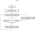
- FIG. 2 is a view showing a control state of the oxidizer discharge valve provided in the oxidizer discharge line according to the embodiment of the present disclosure.
- the oxidizer discharge valve 61 has a structure configured, by a signal from the controller 90, to be opened when the pressure of the oxidizer tank 10 is greater than a set pressure and to be closed when the pressure of the oxidizer tank 10 is no greater than the set pressure of the oxidizer tank 10.
- the pressure value received from the pressure sensor 11 installed in the oxidizer tank 10 is compared with a set value through the controller 90.
- the oxidizer discharge valve 61 is opened, and when the pressure of the oxidizer tank 10 is no higher than the set value, the oxidizer discharge valve 61 is closed. Accordingly, by adjusting the pressure of the oxidizer tank 10 to be constant, stability of the pressure of the oxidizer tank 10, that is, the inlet (front stage) pressure of the oxidizer pump 20, may be secured.
- controller 90 in addition to performing control to maintaining the pressure of the oxidizer tank 10, may regulate the flow rate of the oxidizer pressurized through rotational speed (rpm) control of the electric motor 31 driving the oxidizer pump 20 and perform control function of the main oxidizer supply valve 81 for supplying the oxidizer into the combustion chamber 70.
- the hybrid rocket engine 1 uses the electric motor 31 and the battery 32 to drive the oxidizer pump 20 so as to supply the oxidizer, thereby simplifying the system and reducing the weight of the oxidizer tank 10, so that advantages as a projectile propulsion engine may be maximized.
- the drive unit 30 including the electric motor 31 and battery 32 is cooled by the low-temperature oxidizer being circulated there through.
- the evaporated and pressurized oxidizer is recharged to a top portion of the oxidizer tank 10 so as to replenish an empty space formed due to exhaustion of the oxidizer inside the sealed oxidizer tank 10. Consequentially, a problem of a sudden increase in vacuum and pressure drop may be resolved.
- the pressure in the oxidizer tank 10 is maintained to be constant, whereby a drop in the pressurizing force of the oxidizer may be prevented in advance.
- the present disclosure may prevent a rapid pressure drop in an oxidizer tank from occurring by using pressure generated by an oxidizer evaporated at the same time when a low-temperature oxidizer cools an overheated electric motor and battery.
Landscapes
- Engineering & Computer Science (AREA)
- Chemical & Material Sciences (AREA)
- Combustion & Propulsion (AREA)
- Mechanical Engineering (AREA)
- General Engineering & Computer Science (AREA)
- Testing Of Engines (AREA)
Description
- The present disclosure relates to a hybrid rocket engine using an electric motor-driven oxidizer pump. More particularly, the present disclosure relates to a hybrid rocket engine using an electric motor-driven oxidizer pump that prevents a sudden pressure drop in an oxidizer tank from occurring by using pressure generated by an oxidizer evaporated at the same time when a low-temperature oxidizer cools an overheated electric motor and battery.
- In general, rockets fly by generating thrust with energy generated through combustion of a propellant composed of fuel and oxidizer. Depending on phases of such fuels and oxidizers, rockets are classified into solid, liquid, and hybrid rockets. In the case of the hybrid rocket, the fuel is solid, and the oxidizer is liquid or gas.
- The hybrid rocket has advantages of separating and storing the fuel and the oxidizer and of being capable of controlling thrust and of being stopped and restarted, by controlling the flow rate of the oxidizer. In order to secure such important functions and performances, the oxidizer needs to be reliably supplied, and a separate pressurization system is required therefor.
- In addition, the pressurization system for supplying the oxidizer in the hybrid rocket uses: a self-pressurizing method that uses own properties of the oxidizer, such as nitrous oxide, having high saturated vapor pressure at room temperature, such as nitrous oxide; a gas pressurization method that pressurizes the oxidizer using pressure of a separate high-pressure vessel stored with helium or nitrogen at high pressure; and a turbo pump pressurization method that pressurizes the oxidizer using a pump connected to a turbine driven by the momentum of the combustion gas obtained by combusting the fuel and the oxidizer in a separate device such as a gas generator.
- In the self-pressurizing method, the weight of the oxidizer tank is increased because it is necessary to secure structural rigidity of the oxidizer tank capable of withstanding ullage in the oxidizer tank and an actual oxidizer supply pressure. In addition, as the oxidizer is exhausted, there is a problem that the thrust fluctuations increase due to a sudden pressure drop inside the oxidizer tank.
- In the gas pressurization method, there are drawbacks of: requiring an additional increase in the weight of a projectile as there needs to be a separate high-pressure container that stores inert gases such as helium or nitrogen at high pressure; and of being incapable of supplying the oxidizer to be pressurized in a uniform and stable way due to continuous exhaustion of the pressurizing gas.
- The turbo pump pressurization method using the momentum of the combustion gas generated by the gas generator typically uses a series of systems that drive the turbine with the combustion gas generated by the gas generator and supply the oxidizer by rotating a pump coaxially connected with the turbine.
- In this way, when the gas generator is used as a power source for the pump, the weight of the projectile is increased because the separate oxidizer and fuel need to be loaded. In addition, due to additionally required parts or devices such as the gas generator, the fuel/oxidizer supply device, the turbine, and the like, the rocket is embedded with inherent problems that a structure becomes complicated and the weight is increased.
- Moreover, the turbo pump pressurization method has high effectiveness in a liquid rocket that drives both the fuel pump and the oxidizer pump with a single gas generator and turbine system. However, when the turbo pump pressurization method is applied to a hybrid rocket requiring only pressurization of the oxidizer, the complexity and weight of the hybrid rocket are greatly increased whereas the effectiveness thereof is reduced, thereby reducing the advantages of the hybrid rocket.
- Documents of related art include
Korean Patent No. 10-1682418 (Title of the disclosure: Liquid Rocket Engine Using Pump Driven by Electric Motor, published on Dec. 05, 2016 Korean Patent No. 10-1409938 (Title of the disclosure: Pressure Correcting Apparatus of Turbo pump Engine for Rocket Using Liquid Type Propellants, Publication date: June 13, 2014 - The
CN 107 503 862 A discloses a solid-liquid hybrid rocket combined cycle propelling system. The solid-liquid hybrid rocket combined cycle propelling system comprises an air inlet, a solid-liquid hybrid rocket engine, a super combustion chamber, an exhaust nozzle and an oxidizing agent conveying device. The solid-liquid hybrid rocket engine, the super combustion chamber and the exhaust nozzle are successively communicated in sequence. A combustion chamber and an after-combustion chamber are successively arranged in the solid-liquid hybrid rocket engine. The air inlet is arranged on the circumferential outer side of the solid-liquid hybrid rocket engine and directly communicates with the super combustion chamber. The oxidizing agent conveying device is connected with the combustion chamber and the after-combustion chamber. - The
EP 3 318 745 A1 discloses a liquid rocket engine using a booster pump driven by an electric motor, and more particularly, to a liquid rocket engine using a booster pump driven by an electric motor in which a booster pump is installed between a propellant tank and a propellant pump so that a requirement for an inlet pressure of the propellant pump may be met even in a state in which an internal pressure of the propellant tank is reduced, resulting in reduced amount of a propellant and reduced weight of the propellant tank. - The
US 2016/177874 A1 discloses a device comprising two heat exchangers suitable respectively for vaporizing first and second propellants before they are reintroduced in gaseous form into their tanks. The heat exchangers co-operate respectively with first and second gas generators suitable for being fed with a mixture of propellants in order to produce combustion, the second gas generator being suitable for being fed at least in part by the exhaust from the first gas generator. - Accordingly, the present disclosure has been made keeping in mind the above problems occurring in the related art, and an objective of the present disclosure is to provide a hybrid rocket engine using an electric motor-driven oxidizer pump,which maintains a pressure of a front stage thereof to be constant, thereby being secured to have a reliable oxidizer supply characteristic, by preventing a sudden pressure drop in an oxidizer tank from occurring using pressure, which is generated by an oxidizer evaporated at the same time when a low-temperature oxidizer cools an overheated electric motor and battery.
- According to one aspect of the invention a hybrid rocket engine according to
claim 1 is provided, the hybrid rocket engine being configured for using a solid fuel and a liquid or gaseous oxidizer, the hybrid rocket engine including: an oxidizer tank configured to store an oxidizer; an oxidizer pump configured to pressurize the oxidizer by being connected to the oxidizer tank through a first oxidizer supply line; a drive unit including an electric motor configured to drive the oxidizer pump and a battery configured to supply power to an electric motor; an auxiliary oxidizer line configured to guide the oxidizer from the oxidizer tank to the electric motor to cool the electric motor of the drive unit; an oxidizer recirculation line configured to recharge oxidizer vapor, generated through heat exchange between the electric motor and the oxidizer, to the oxidizer tank, thereby pressurizing an inner side of the oxidizer tank; and a combustion chamber configured to combust the oxidizer and fuel by being connected to the oxidizer pump through a second oxidizer supply line. - The auxiliary oxidizer line may have a structure configured to supply a portion of the oxidizer supplied through the first oxidizer supply line to the electric motor and to maintain a pressure of the oxidizer tank to be constant by feeding oxidizer vapor, generated when the electric motor is cooled, to the oxidizer tank through the oxidizer recirculation line.
- The hybrid rocket engine using the electric motor-driven oxidizer pump may include an oxidizer discharge line configured to discharge the oxidizer to the outside by being branched off the oxidizer recirculation line, wherein the oxidizer discharge line may include an oxidizer discharge valve that may be opened to discharge the oxidizer or closed, and the second oxidizer supply line may include a main oxidizer supply valve that may be opened to supply the oxidizer to the combustion chamber or closed.
- The oxidizer tank may include a pressure sensor configured to measure pressure inside the oxidizer tank and may further include a controller configured to receive data from the pressure sensor and to control the oxidizer discharge valve, the main oxidizer supply valve, and the electric motor according to a set algorithm.
- The oxidizer discharge valve may have a structure configured to be opened when the pressure of the oxidizer tank is greater than set pressure and to be closed when the pressure of the oxidizer tank is no greater than the set pressure of the oxidizer tank.
- According to the hybrid rocket engine using the electric motor-driven oxidizer pump according to the present disclosure, the electric motor and the battery are used to drive the pump so as to supply the oxidizer, thereby simplifying the pressurization system and reducing the weight of the oxidizer tank, so that advantages as a projectile propulsion engine can be maximized.
- In addition, the electric drive unit including the electric motor and battery is cooled by the low-temperature oxidizer being circulated there through. Through this process, the evaporated and pressurized oxidizer is recharged to a top portion of the oxidizer tank so as to replenish an empty space formed due to exhaustion of the oxidizer inside the sealed oxidizer tank. Consequentially, a problem of a sudden increase in vacuum and pressure drop can be resolved.
- In addition, pressure in the oxidizer tank is maintained to be constant, whereby a drop in the pressurizing force of the oxidizer can be prevented in advance.
-
-
FIG. 1 is a view showing a structure of a hybrid rocket engine using an electric motor-driven oxidizer pump according to an embodiment of the present disclosure. -
FIG. 2 is a view showing a control state of an oxidizer discharge valve provided in an oxidizer discharge line according to an embodiment of the present disclosure. - Hereinafter, an embodiment of a hybrid rocket engine using an electric motor-driven oxidizer pump according to the present disclosure will be described with reference to accompanying drawings. In this case, the present disclosure is not limited to or restricted by the embodiment. In addition, in describing the present disclosure, detailed descriptions of known functions or configurations may be omitted to clarify the scope of the present disclosure.
-
FIG. 1 is a view showing a structure of a hybrid rocket engine using an electric motor-driven oxidizer pump according to an embodiment of the present disclosure. - With a reference to
FIG. 1 , ahybrid rocket engine 1 using the electric motor-driven oxidizer pump, which maintains the pressure of anoxidizer tank 10, thereby preventing the pressurizing force of an oxidizer from being dropped, is disclosed. - A combustion process of the propellants in the
combustion chamber 70 is required to obtain propulsion in thehybrid rocket engine 1, and to this end, the oxidizer should be supplied into thecombustion chamber 70 in which solid fuel is mounted. - In the present embodiment, the
hybrid rocket engine 1 includes theoxidizer tank 10, anoxidizer pump 20, adrive unit 30, anauxiliary oxidizer line 40, anoxidizer recirculation line 50, an oxidizer discharge line 60, and acombustion chamber 70. - The
hybrid rocket engine 1 includes: theoxidizer tank 10 configured to store the oxidizer; theoxidizer pump 20 configured to pressurize the oxidizer by being connected to theoxidizer tank 10 through a firstoxidizer supply line 80A; thedrive unit 30 including anelectric motor 31 configured to drive theoxidizer pump 20 and abattery 32 configured to supply power to theelectric motor 31; and theauxiliary oxidizer line 40 configured to guide the oxidizer from theoxidizer tank 10 to cool thedrive unit 30. - In addition, the
hybrid rocket engine 1 includes: theoxidizer recirculation line 50 configured to guide the oxidizer to be recharged to theoxidizer tank 10 after the oxidizer has been circulated through thedrive unit 30; the oxidizer discharge line 60 configured to discharge the oxidizer to the outside by being branched off theoxidizer recirculation line 50; and thecombustion chamber 70 configured to combust the oxidizer and fuel by being connected to theoxidizer pump 20 through a secondoxidizer supply line 80B. - That is, the
auxiliary oxidizer line 40 has a structure configured to cool theelectric motor 31 by supplying a portion of the oxidizer supplied through the firstoxidizer supply line 80A to theelectric motor 31 and to pressurize theoxidizer tank 10 by filling the oxidizer therein by the pressure generated by evaporation of the oxidizer through heat exchange between theelectric motor 31 and the oxidizer. - The oxidizer discharge line 60 includes an
oxidizer discharge valve 61 that is opened to discharge the oxidizer or closed, and the secondoxidizer supply line 80B includes a mainoxidizer supply valve 81 that is opened to supply the oxidizer to thecombustion chamber 70 or closed. - In the present embodiment, the
oxidizer tank 10 of thehybrid rocket engine 1 includes: apressure sensor 11 configured to measure pressure inside theoxidizer tank 10; and acontroller 90 configured to receive data from thepressure sensor 11 and to control theoxidizer discharge valve 61, the mainoxidizer supply valve 81, and theelectric motor 31 according to a set algorithm. - In the meanwhile, propulsion performance such as thrust is very important in a function of a rocket. In chemical rockets including hybrid rockets, high-temperature and high-pressure gas generated by combusting propellants in the
combustion chamber 70 is ejected at high speed through a nozzle to generate the thrust. Therefore, the propulsion performance is greatly affected by the combustion performance and characteristics of the rocket engine. - Therefore, in the
hybrid rocket engine 1, a regression rate, which is a speed at which the solid fuel is combusted, is used as a combustion rate representing combustion performance and may be expressed by a generalized relational equation, which is an empirical equation, as follows.
where γ is the regression rate, a and n are empirical constants, and Go is an oxidizer mass flow rate, which is the oxidizer mass flow rate per unit area. - As may be seen from the above relational equation, the combustion performance of the
hybrid rocket engine 1 is directly related to the oxidizer mass flow rate. - In general, the mass flow rate may be expressed as follows as a function of a pressure difference between an inlet (front stage) and an outlet (rear stage) in control volume, and the mass flow rate may be changed by adjusting the pressure.


where m is the mass flow rate of the fluid,is the density of the fluid, A is the cross sectional area of the fluid, v is the velocity of the fluid, and ΔP is the pressure difference between the pre stage and rear stage in the test volume.
- That is, in the case of the
hybrid rocket engine 1, the thrust may be controlled by adjusting the oxidizer mass flow rate according to a pressure condition at which the oxidizer supply is made to thecombustion chamber 70, and a stable oxidizer supply pressure plays an important role as one factor of propulsion performance. - In the present embodiment, when the oxidizer is to be supplied to the
combustion chamber 70, thehybrid rocket engine 1 uses theoxidizer pump 20 driven by theelectric motor 31 in order to pressurize the oxidizer. The inlet (front stage) pressure of theoxidizer pump 20 is controlled by the pressure of theoxidizer tank 10, and the pressure of the outlet (rear stage) of theoxidizer pump 20 is pressure at which the oxidizer having been pressurized at a regular compression ratio by theoxidizer pump 20 is discharged and also becomes the oxidizer supply pressure applied to thecombustion chamber 70. - When the pressure of the
oxidizer tank 10 rapidly fluctuates, such as when the oxidizer in theoxidizer tank 10 is rapidly exhausted with the operation of theoxidizer pump 20, a sudden change in the inlet (front stage) pressure of theoxidizer pump 20 occurs, causing shock and damage to the impeller of theoxidizer pump 20 due to cavitation in theoxidizer pump 20 or resulting in non-uniformity and instability of the pressure of the oxidizer being supplied to the combustion chamber. - Accordingly, a separate pressurization system may be required to ensure the stability of the inlet (front stage) pressure of the
oxidizer pump 20. However, in thehybrid rocket engine 1 using the electric motor-driven oxidizer pump, with the oxidizer cooling thedrive unit 30 including theelectric motor 31 and thebattery 32 through the circulation thereto, the low-temperature oxidizer is evaporated and pressurized so as to be recharged into theoxidizer tank 10, whereby a separate pressurization system may be eliminated and the oxidizer supply system in thehybrid rocket engine 1 may be simplified. -
FIG. 2 is a view showing a control state of the oxidizer discharge valve provided in the oxidizer discharge line according to the embodiment of the present disclosure. - With a reference to
FIG. 2 , theoxidizer discharge valve 61 has a structure configured, by a signal from thecontroller 90, to be opened when the pressure of theoxidizer tank 10 is greater than a set pressure and to be closed when the pressure of theoxidizer tank 10 is no greater than the set pressure of theoxidizer tank 10. - That is, the pressure value received from the
pressure sensor 11 installed in theoxidizer tank 10 is compared with a set value through thecontroller 90. When the pressure of theoxidizer tank 10 is higher than the set value, theoxidizer discharge valve 61 is opened, and when the pressure of theoxidizer tank 10 is no higher than the set value, theoxidizer discharge valve 61 is closed. Accordingly, by adjusting the pressure of theoxidizer tank 10 to be constant, stability of the pressure of theoxidizer tank 10, that is, the inlet (front stage) pressure of theoxidizer pump 20, may be secured. - In addition, the
controller 90, in addition to performing control to maintaining the pressure of theoxidizer tank 10, may regulate the flow rate of the oxidizer pressurized through rotational speed (rpm) control of theelectric motor 31 driving theoxidizer pump 20 and perform control function of the mainoxidizer supply valve 81 for supplying the oxidizer into thecombustion chamber 70. - Therefore, the
hybrid rocket engine 1 uses theelectric motor 31 and thebattery 32 to drive theoxidizer pump 20 so as to supply the oxidizer, thereby simplifying the system and reducing the weight of theoxidizer tank 10, so that advantages as a projectile propulsion engine may be maximized. - In addition, the
drive unit 30 including theelectric motor 31 andbattery 32 is cooled by the low-temperature oxidizer being circulated there through. Through this process, the evaporated and pressurized oxidizer is recharged to a top portion of theoxidizer tank 10 so as to replenish an empty space formed due to exhaustion of the oxidizer inside the sealedoxidizer tank 10. Consequentially, a problem of a sudden increase in vacuum and pressure drop may be resolved. - In addition, the pressure in the
oxidizer tank 10 is maintained to be constant, whereby a drop in the pressurizing force of the oxidizer may be prevented in advance. - As above, the present disclosure has been shown and described in connection with an exemplary embodiment for illustrating the principle of the present disclosure. However, the present disclosure is not limited to the configuration and operation the same as shown and described as such. Rather, it will be well understood by those skilled in the art that a number of changes and modifications may be made to the present disclosure without departing from the invention, which is defined in the appended claims.
- The present disclosure may prevent a rapid pressure drop in an oxidizer tank from occurring by using pressure generated by an oxidizer evaporated at the same time when a low-temperature oxidizer cools an overheated electric motor and battery.
Claims (5)
- A hybrid rocket engine (1) configured for using a solid fuel and a liquid or gaseous oxidizer, the hybrid rocket engine (1) comprising:an oxidizer tank (10) configured to store an oxidizer;an oxidizer pump (20) configured to pressurize the oxidizer by being connected to the oxidizer tank (10) through a first oxidizer supply line (80A); anda drive unit (30) comprising an electric motor (31) configured to drive the oxidizer pump (20) and a battery (32) configured to supply power to the electric motor (31); characterized byan auxiliary oxidizer line (40) configured to guide the oxidizer from the oxidizer tank (10) to the electric motor (31) to cool the electric motor (31) of the drive unit (30);an oxidizer recirculation line (50) configured to recharge oxidizer vapor, generated through heat exchange between the electric motor (31) and the oxidizer, to the oxidizer tank (10), thereby pressurizing an inner side of the oxidizer tank (10); anda combustion chamber (70) configured to combust the oxidizer and fuel by being connected to the oxidizer pump (20) through a second oxidizer supply line (80B).
- The hybrid rocket engine (1) of claim 1, wherein the auxiliary oxidizer line (40) has a structure configured to supply a portion of the oxidizer supplied through the first oxidizer supply line (80A) to the electric motor (31) and to maintain pressure of the oxidizer tank (10) to be constant by feeding oxidizer vapor, generated when the electric motor (31) is cooled, to the oxidizer tank (10) through the oxidizer recirculation line (50).
- The hybrid rocket engine (1) of claim 1, further comprising an oxidizer discharge line (60) configured to discharge the oxidizer to the outside by being branched off the oxidizer recirculation line (50), wherein the oxidizer discharge line (60) comprises an oxidizer discharge valve (61) that is opened to discharge the oxidizer or closed, and the second oxidizer supply line (80B) comprises a main oxidizer supply valve (81) that is opened to supply the oxidizer to the combustion chamber (70) or closed.
- The hybrid rocket engine (1) of claim 3, wherein the oxidizer tank (10) comprises a pressure sensor (11) configured to measure pressure inside the oxidizer tank (10) and further comprises a controller (90) configured to receive data from the pressure sensor (11) and to control the oxidizer discharge valve (61), the main oxidizer supply valve (81), and the electric motor (31) according to a set algorithm.
- The hybrid rocket engine of claim 4, wherein the oxidizer discharge valve (61) has a structure configured to be opened when the pressure of the oxidizer tank (10) is greater than set pressure and to be closed when the pressure of the oxidizer tank (10) is no greater than the set pressure of the oxidizer tank (10) .
Applications Claiming Priority (2)
| Application Number | Priority Date | Filing Date | Title |
|---|---|---|---|
| KR1020180151430A KR102101659B1 (en) | 2018-11-29 | 2018-11-29 | Hybrid rocket engine using electric motor driven oxidizer pump |
| PCT/KR2019/015798 WO2020111622A1 (en) | 2018-11-29 | 2019-11-19 | Hybrid rocket engine using electric motor-driven oxidizer pump |
Publications (4)
| Publication Number | Publication Date |
|---|---|
| EP3889416A1 EP3889416A1 (en) | 2021-10-06 |
| EP3889416A4 EP3889416A4 (en) | 2022-08-24 |
| EP3889416B1 true EP3889416B1 (en) | 2024-08-28 |
| EP3889416C0 EP3889416C0 (en) | 2024-08-28 |
Family
ID=70460703
Family Applications (1)
| Application Number | Title | Priority Date | Filing Date |
|---|---|---|---|
| EP19890922.8A Active EP3889416B1 (en) | 2018-11-29 | 2019-11-19 | Hybrid rocket engine using electric motor-driven oxidizer pump |
Country Status (5)
| Country | Link |
|---|---|
| US (1) | US11649786B2 (en) |
| EP (1) | EP3889416B1 (en) |
| KR (1) | KR102101659B1 (en) |
| AU (1) | AU2019390971B2 (en) |
| WO (1) | WO2020111622A1 (en) |
Families Citing this family (5)
| Publication number | Priority date | Publication date | Assignee | Title |
|---|---|---|---|---|
| CN112697439B (en) * | 2020-12-04 | 2022-05-17 | 江苏深蓝航天有限公司 | Complete machine liquid flow test system and method for electric pump circulation rocket engine |
| CN114508447B (en) * | 2022-02-17 | 2024-03-22 | 北京航空航天大学 | Electric pumping type solid-liquid rocket engine test conveying system and method |
| KR102791625B1 (en) * | 2022-03-28 | 2025-04-08 | (주)이노스페이스 | Oxidizer supply device and hybrid rocket equipped with this |
| KR102752585B1 (en) * | 2022-03-28 | 2025-01-10 | (주)이노스페이스 | Roll controlled thruster and hybrid rocket equipped with this |
| WO2025239563A1 (en) * | 2024-05-14 | 2025-11-20 | 우나스텔라 주식회사 | Electric-pump cycle liquid rocket engine with oxidant bypass system for cooling, pressurization and ignition |
Family Cites Families (13)
| Publication number | Priority date | Publication date | Assignee | Title |
|---|---|---|---|---|
| US3170295A (en) * | 1963-04-09 | 1965-02-23 | Hugh L Dryden | Propellant tank pressurization system |
| US4741502A (en) * | 1985-10-01 | 1988-05-03 | Hughes Aircraft Company | Method and apparatus for launching a spacecraft by use of a recoverable upper rocket stage |
| US6314978B1 (en) * | 1996-02-21 | 2001-11-13 | Mcdonnell Douglas Corporation | Reciprocating feed system for fluids |
| US5765361A (en) * | 1996-08-23 | 1998-06-16 | Jones; Herbert Stephen | Hybrid-LO2-LH2 low cost launch vehicle |
| US7389636B2 (en) | 2005-07-06 | 2008-06-24 | United Technologies Corporation | Booster rocket engine using gaseous hydrocarbon in catalytically enhanced gas generator cycle |
| FR2921980B1 (en) * | 2007-10-08 | 2014-05-09 | Astrium Sas | DEVICE AND METHOD FOR PUMP MOTORIZATION FOR INERTIAL WHEEL ENGINE |
| KR101409938B1 (en) | 2013-01-16 | 2014-06-20 | 한국항공우주연구원 | Pressure correcting apparatus of turbo-pump engine for rocket using liquid type propellant |
| US20140260186A1 (en) * | 2013-03-15 | 2014-09-18 | Patrick R.E. Bahn | Rocket engine systems with an independently regulated cooling system |
| FR3009587B1 (en) * | 2013-08-06 | 2015-08-28 | Snecma | PRESSURIZATION DEVICE FOR ERGOL TANKS OF A ROTOR MOTOR |
| FR3032750B1 (en) * | 2015-02-12 | 2018-11-16 | Arianegroup Sas | DEVICE FOR PRESSURIZING A LIQUID OXYGEN RESERVOIR OF A ROTOR MOTOR |
| KR101682418B1 (en) | 2015-09-14 | 2016-12-05 | 한국항공우주연구원 | Liquid rocket engine, which uses a pump driven by an electric motor |
| KR102041568B1 (en) * | 2015-09-14 | 2019-11-06 | 한국항공우주연구원 | Liquid rocket engine using booster pump driven by electric motor |
| CN107503862A (en) * | 2017-10-10 | 2017-12-22 | 北京航空航天大学 | A kind of hybrid rocket combination circulation propulsion system and its control method |
-
2018
- 2018-11-29 KR KR1020180151430A patent/KR102101659B1/en active Active
-
2019
- 2019-11-19 EP EP19890922.8A patent/EP3889416B1/en active Active
- 2019-11-19 AU AU2019390971A patent/AU2019390971B2/en active Active
- 2019-11-19 WO PCT/KR2019/015798 patent/WO2020111622A1/en not_active Ceased
- 2019-11-19 US US17/293,127 patent/US11649786B2/en active Active
Also Published As
| Publication number | Publication date |
|---|---|
| AU2019390971B2 (en) | 2022-12-01 |
| AU2019390971A1 (en) | 2021-05-27 |
| US20220003188A1 (en) | 2022-01-06 |
| US11649786B2 (en) | 2023-05-16 |
| EP3889416A1 (en) | 2021-10-06 |
| EP3889416A4 (en) | 2022-08-24 |
| WO2020111622A1 (en) | 2020-06-04 |
| BR112021009337A2 (en) | 2021-08-17 |
| KR102101659B1 (en) | 2020-04-17 |
| EP3889416C0 (en) | 2024-08-28 |
Similar Documents
| Publication | Publication Date | Title |
|---|---|---|
| EP3889416B1 (en) | Hybrid rocket engine using electric motor-driven oxidizer pump | |
| EP3447274B1 (en) | Electric power-assisted liquid-propellant rocket propulsion system | |
| US8572948B1 (en) | Rocket engine propulsion system | |
| US11181076B2 (en) | Rocket engine bipropellant supply system including an electrolyzer | |
| CN101821492B (en) | Method and device enabling rocket engine pump to be driven by internal combustion engine | |
| JP6289652B2 (en) | Apparatus, systems, and methods for pressurizing and delivering fluids. | |
| JP6573602B2 (en) | Storage pressure drive cycle | |
| US20140283499A1 (en) | Device and a method for feeding a rocket engine propulsion chamber | |
| JP5546456B2 (en) | Device for powering rocket engine pumps using inertial disks | |
| US5648052A (en) | Liquid monopropellant gas generator | |
| WO1996008646A1 (en) | Solid-fuel, liquid oxidizer hybrid rocket turbopump auxiliary engine | |
| US20150143797A1 (en) | Turbopump | |
| ES2988249T3 (en) | Rocket propulsion system, procedure and space vehicle | |
| US5873241A (en) | Rocket engine auxiliary power system | |
| EP2761159B1 (en) | Propulsion system | |
| JP2001329911A (en) | Hybrid rocket engine and its pump driving method | |
| US20230313758A1 (en) | Feed system for rocket engine | |
| BR112021009337B1 (en) | HYBRID ROCKET ENGINE USING AN ELECTRIC MOTOR-DRIVED OXIDIZER PUMP | |
| US11598288B2 (en) | Motor and fuel-powered hybrid system for a rocket thruster | |
| KR20230139586A (en) | Oxidizer supply device and hybrid rocket equipped with this |
Legal Events
| Date | Code | Title | Description |
|---|---|---|---|
| STAA | Information on the status of an ep patent application or granted ep patent |
Free format text: STATUS: THE INTERNATIONAL PUBLICATION HAS BEEN MADE |
|
| PUAI | Public reference made under article 153(3) epc to a published international application that has entered the european phase |
Free format text: ORIGINAL CODE: 0009012 |
|
| STAA | Information on the status of an ep patent application or granted ep patent |
Free format text: STATUS: REQUEST FOR EXAMINATION WAS MADE |
|
| 17P | Request for examination filed |
Effective date: 20210505 |
|
| AK | Designated contracting states |
Kind code of ref document: A1 Designated state(s): AL AT BE BG CH CY CZ DE DK EE ES FI FR GB GR HR HU IE IS IT LI LT LU LV MC MK MT NL NO PL PT RO RS SE SI SK SM TR |
|
| DAV | Request for validation of the european patent (deleted) | ||
| DAX | Request for extension of the european patent (deleted) | ||
| A4 | Supplementary search report drawn up and despatched |
Effective date: 20220722 |
|
| RIC1 | Information provided on ipc code assigned before grant |
Ipc: F02K 9/72 20060101ALI20220718BHEP Ipc: F02K 9/56 20060101ALI20220718BHEP Ipc: F02K 9/46 20060101AFI20220718BHEP |
|
| GRAP | Despatch of communication of intention to grant a patent |
Free format text: ORIGINAL CODE: EPIDOSNIGR1 |
|
| STAA | Information on the status of an ep patent application or granted ep patent |
Free format text: STATUS: GRANT OF PATENT IS INTENDED |
|
| INTG | Intention to grant announced |
Effective date: 20240426 |
|
| GRAS | Grant fee paid |
Free format text: ORIGINAL CODE: EPIDOSNIGR3 |
|
| GRAA | (expected) grant |
Free format text: ORIGINAL CODE: 0009210 |
|
| STAA | Information on the status of an ep patent application or granted ep patent |
Free format text: STATUS: THE PATENT HAS BEEN GRANTED |
|
| RAP3 | Party data changed (applicant data changed or rights of an application transferred) |
Owner name: INNOSPACE CO., LTD. |
|
| AK | Designated contracting states |
Kind code of ref document: B1 Designated state(s): AL AT BE BG CH CY CZ DE DK EE ES FI FR GB GR HR HU IE IS IT LI LT LU LV MC MK MT NL NO PL PT RO RS SE SI SK SM TR |
|
| REG | Reference to a national code |
Ref country code: CH Ref legal event code: EP |
|
| REG | Reference to a national code |
Ref country code: DE Ref legal event code: R096 Ref document number: 602019058079 Country of ref document: DE |
|
| REG | Reference to a national code |
Ref country code: IE Ref legal event code: FG4D |
|
| U01 | Request for unitary effect filed |
Effective date: 20240828 |
|
| U07 | Unitary effect registered |
Designated state(s): AT BE BG DE DK EE FI FR IT LT LU LV MT NL PT RO SE SI Effective date: 20240904 |
|
| U20 | Renewal fee for the european patent with unitary effect paid |
Year of fee payment: 6 Effective date: 20241125 |
|
| PG25 | Lapsed in a contracting state [announced via postgrant information from national office to epo] |
Ref country code: GR Free format text: LAPSE BECAUSE OF FAILURE TO SUBMIT A TRANSLATION OF THE DESCRIPTION OR TO PAY THE FEE WITHIN THE PRESCRIBED TIME-LIMIT Effective date: 20241129 Ref country code: PL Free format text: LAPSE BECAUSE OF FAILURE TO SUBMIT A TRANSLATION OF THE DESCRIPTION OR TO PAY THE FEE WITHIN THE PRESCRIBED TIME-LIMIT Effective date: 20240828 |
|
| PG25 | Lapsed in a contracting state [announced via postgrant information from national office to epo] |
Ref country code: IS Free format text: LAPSE BECAUSE OF FAILURE TO SUBMIT A TRANSLATION OF THE DESCRIPTION OR TO PAY THE FEE WITHIN THE PRESCRIBED TIME-LIMIT Effective date: 20241228 |
|
| PG25 | Lapsed in a contracting state [announced via postgrant information from national office to epo] |
Ref country code: HR Free format text: LAPSE BECAUSE OF FAILURE TO SUBMIT A TRANSLATION OF THE DESCRIPTION OR TO PAY THE FEE WITHIN THE PRESCRIBED TIME-LIMIT Effective date: 20240828 |
|
| PG25 | Lapsed in a contracting state [announced via postgrant information from national office to epo] |
Ref country code: ES Free format text: LAPSE BECAUSE OF FAILURE TO SUBMIT A TRANSLATION OF THE DESCRIPTION OR TO PAY THE FEE WITHIN THE PRESCRIBED TIME-LIMIT Effective date: 20240828 Ref country code: RS Free format text: LAPSE BECAUSE OF FAILURE TO SUBMIT A TRANSLATION OF THE DESCRIPTION OR TO PAY THE FEE WITHIN THE PRESCRIBED TIME-LIMIT Effective date: 20241128 |
|
| PG25 | Lapsed in a contracting state [announced via postgrant information from national office to epo] |
Ref country code: RS Free format text: LAPSE BECAUSE OF FAILURE TO SUBMIT A TRANSLATION OF THE DESCRIPTION OR TO PAY THE FEE WITHIN THE PRESCRIBED TIME-LIMIT Effective date: 20241128 Ref country code: PL Free format text: LAPSE BECAUSE OF FAILURE TO SUBMIT A TRANSLATION OF THE DESCRIPTION OR TO PAY THE FEE WITHIN THE PRESCRIBED TIME-LIMIT Effective date: 20240828 Ref country code: IS Free format text: LAPSE BECAUSE OF FAILURE TO SUBMIT A TRANSLATION OF THE DESCRIPTION OR TO PAY THE FEE WITHIN THE PRESCRIBED TIME-LIMIT Effective date: 20241228 Ref country code: HR Free format text: LAPSE BECAUSE OF FAILURE TO SUBMIT A TRANSLATION OF THE DESCRIPTION OR TO PAY THE FEE WITHIN THE PRESCRIBED TIME-LIMIT Effective date: 20240828 Ref country code: GR Free format text: LAPSE BECAUSE OF FAILURE TO SUBMIT A TRANSLATION OF THE DESCRIPTION OR TO PAY THE FEE WITHIN THE PRESCRIBED TIME-LIMIT Effective date: 20241129 Ref country code: ES Free format text: LAPSE BECAUSE OF FAILURE TO SUBMIT A TRANSLATION OF THE DESCRIPTION OR TO PAY THE FEE WITHIN THE PRESCRIBED TIME-LIMIT Effective date: 20240828 |
|
| PG25 | Lapsed in a contracting state [announced via postgrant information from national office to epo] |
Ref country code: SM Free format text: LAPSE BECAUSE OF FAILURE TO SUBMIT A TRANSLATION OF THE DESCRIPTION OR TO PAY THE FEE WITHIN THE PRESCRIBED TIME-LIMIT Effective date: 20240828 |
|
| PG25 | Lapsed in a contracting state [announced via postgrant information from national office to epo] |
Ref country code: CZ Free format text: LAPSE BECAUSE OF FAILURE TO SUBMIT A TRANSLATION OF THE DESCRIPTION OR TO PAY THE FEE WITHIN THE PRESCRIBED TIME-LIMIT Effective date: 20240828 |
|
| PG25 | Lapsed in a contracting state [announced via postgrant information from national office to epo] |
Ref country code: SK Free format text: LAPSE BECAUSE OF FAILURE TO SUBMIT A TRANSLATION OF THE DESCRIPTION OR TO PAY THE FEE WITHIN THE PRESCRIBED TIME-LIMIT Effective date: 20240828 |
|
| REG | Reference to a national code |
Ref country code: CH Ref legal event code: PL |
|
| PLBE | No opposition filed within time limit |
Free format text: ORIGINAL CODE: 0009261 |
|
| STAA | Information on the status of an ep patent application or granted ep patent |
Free format text: STATUS: NO OPPOSITION FILED WITHIN TIME LIMIT |
|
| PG25 | Lapsed in a contracting state [announced via postgrant information from national office to epo] |
Ref country code: MC Free format text: LAPSE BECAUSE OF FAILURE TO SUBMIT A TRANSLATION OF THE DESCRIPTION OR TO PAY THE FEE WITHIN THE PRESCRIBED TIME-LIMIT Effective date: 20240828 |
|
| REG | Reference to a national code |
Ref country code: CH Ref legal event code: PL |
|
| GBPC | Gb: european patent ceased through non-payment of renewal fee |
Effective date: 20241128 |
|
| PG25 | Lapsed in a contracting state [announced via postgrant information from national office to epo] |
Ref country code: CH Free format text: LAPSE BECAUSE OF NON-PAYMENT OF DUE FEES Effective date: 20241130 |
|
| 26N | No opposition filed |
Effective date: 20250530 |
|
| PG25 | Lapsed in a contracting state [announced via postgrant information from national office to epo] |
Ref country code: GB Free format text: LAPSE BECAUSE OF NON-PAYMENT OF DUE FEES Effective date: 20241128 |
|
| PG25 | Lapsed in a contracting state [announced via postgrant information from national office to epo] |
Ref country code: IE Free format text: LAPSE BECAUSE OF NON-PAYMENT OF DUE FEES Effective date: 20241119 |
|
| U20 | Renewal fee for the european patent with unitary effect paid |
Year of fee payment: 7 Effective date: 20251117 |
|
| PGFP | Annual fee paid to national office [announced via postgrant information from national office to epo] |
Ref country code: NO Payment date: 20251118 Year of fee payment: 7 |
|
| PG25 | Lapsed in a contracting state [announced via postgrant information from national office to epo] |
Ref country code: HU Free format text: LAPSE BECAUSE OF FAILURE TO SUBMIT A TRANSLATION OF THE DESCRIPTION OR TO PAY THE FEE WITHIN THE PRESCRIBED TIME-LIMIT; INVALID AB INITIO Effective date: 20191119 |
|
| PG25 | Lapsed in a contracting state [announced via postgrant information from national office to epo] |
Ref country code: CY Free format text: LAPSE BECAUSE OF FAILURE TO SUBMIT A TRANSLATION OF THE DESCRIPTION OR TO PAY THE FEE WITHIN THE PRESCRIBED TIME-LIMIT; INVALID AB INITIO Effective date: 20191119 |