EP3889050A1 - Assisted refueling boom actuator - Google Patents
Assisted refueling boom actuator Download PDFInfo
- Publication number
- EP3889050A1 EP3889050A1 EP20217050.2A EP20217050A EP3889050A1 EP 3889050 A1 EP3889050 A1 EP 3889050A1 EP 20217050 A EP20217050 A EP 20217050A EP 3889050 A1 EP3889050 A1 EP 3889050A1
- Authority
- EP
- European Patent Office
- Prior art keywords
- boom
- hoist
- refueling boom
- refueling
- aircraft
- Prior art date
- Legal status (The legal status is an assumption and is not a legal conclusion. Google has not performed a legal analysis and makes no representation as to the accuracy of the status listed.)
- Granted
Links
Images



Classifications
-
- B—PERFORMING OPERATIONS; TRANSPORTING
- B64—AIRCRAFT; AVIATION; COSMONAUTICS
- B64D—EQUIPMENT FOR FITTING IN OR TO AIRCRAFT; FLIGHT SUITS; PARACHUTES; ARRANGEMENT OR MOUNTING OF POWER PLANTS OR PROPULSION TRANSMISSIONS IN AIRCRAFT
- B64D39/00—Refuelling during flight
- B64D39/04—Adaptations of hose construction
-
- B—PERFORMING OPERATIONS; TRANSPORTING
- B64—AIRCRAFT; AVIATION; COSMONAUTICS
- B64D—EQUIPMENT FOR FITTING IN OR TO AIRCRAFT; FLIGHT SUITS; PARACHUTES; ARRANGEMENT OR MOUNTING OF POWER PLANTS OR PROPULSION TRANSMISSIONS IN AIRCRAFT
- B64D39/00—Refuelling during flight
- B64D39/02—Means for paying-in or out hose
Definitions
- Certain aerial refueling aircraft utilize an aerial refueling boom to perform refueling.
- the refueling boom when in the stowed position, is latched to the fuselage of the aircraft.
- a boom aerodynamic control surface of the refueling boom When a deployment of the refueling boom is commanded, a boom aerodynamic control surface of the refueling boom generates aerodynamic lift to raise the refueling boom off a latch.
- the latch is then opened once the refueling boom is lifted, before the refueling boom is then lowered.
- the boom aerodynamic control surface then provides aerodynamic control to fly the refueling boom away from the fuselage.
- the boom aerodynamic control surface flies the refueling boom up to the fuselage, the latch is closed and the refueling boom is accordingly coupled to the fuselage.
- the technique includes lowering, while a hoist of a refueling boom is in a second actuator state mode, a refueling boom structure of the refueling boom with the hoist while a boom aerodynamic control surface of the refueling boom is deactivated, determining that first transition conditions have been met, switching the hoist from the second actuator state mode to a first actuator state mode, and activating the boom aerodynamic control surface.
- the technique includes flying a refueling boom towards a fuselage of an aircraft while a hoist of the refueling boom is in a zero actuator state mode, determining that second transition conditions have been met, switching the hoist from the zero actuator state mode to a first actuator state mode, and raising a refueling boom structure of the refueling boom with the hoist.
- the refueling boom structure in certain examples, includes a boom aerodynamic control surface which is deactivated while the hoist is in a second actuator state mode.
- the refueling boom control techniques include lowering a refueling boom structure with a hoist while the hoist is in the second actuator state mode, determining that first transition conditions have been met, switching the hoist from the second actuator state mode to a first actuator state mode, and activating the boom aerodynamic control surface after the hoist is in the first actuator state mode.
- aerial refueling aircrafts include an aerial refueling boom.
- the aerial refueling boom is located along the fuselage of the aircraft in certain examples and is stowed by being latched to the fuselage of the aircraft.
- a boom aerodynamic control surface e.g., a boom elevator
- the latch is then opened once the refueling boom is lifted, before the refueling boom is then lowered.
- the boom aerodynamic control surface then provides control to fly the refueling boom away from the fuselage.
- the boom aerodynamic control surface flies the refueling boom up to the fuselage and the refueling boom is accordingly latched to the fuselage.
- a single command stow and deploy throughout the entire aerial refueling envelope improves usability and is required in certain applications.
- the boom aerodynamic control surface does not generate enough aerodynamic lift to lift the boom up above the latch.
- the hoist is used to lift the boom off the latch instead.
- the techniques described herein are used as a retrofit or update to existing systems.
- Certain existing systems include hoists that are not originally intended to be used in the deploying the refueling boom.
- hoist actuator controlling movement of the hoist
- aerodynamic actuator controlling movement of the boom aerodynamic control surface
- the techniques described herein allow for coordination and collaborative efforts between the two dissimilar actuators (e.g., the hoist actuator and the elevator actuator) to allow for single button stow and deploy throughout the aerial refueling envelope.
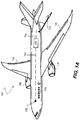
- FIG. 1A illustrates a vehicle with a refueling boom, in accordance with some examples.
- FIG. 1A illustrates vehicle 100 that is a fixed wing aircraft, but other examples include other structures (e.g., helicopters, variable wing aircraft, short takeoff and landing aircraft, spacecraft, drones, and other such vehicles).
- Vehicle 100 includes fuselage 120, wings 140, and aircraft propulsors 130. Each of aircraft propulsors 130 are coupled to a respective wing 140. Wings 140 are coupled to fuselage 120. Vehicle 100 further includes refueling boom 110 coupled to a portion of fuselage 120 (e.g., an aft fuselage 120). Further details of refueling boom 110 are shown and described in FIG. 1B .
- Controller 150 includes, in various examples, a memory, a processor, and other logic device components. Controller 150 receives data, performs calculations, and provides outputs (e.g., control instructions) to various other portions of vehicle 100. Controller 150 is communicatively coupled to refueling boom 110 through communication network 154. In certain examples, communication network 154 is any type of wired and/or wireless network that communicates data and/or power to and from controller 150. Controller 150 is also coupled to sensors 152 via communication network 154. Sensors 152 include air speed, air pressure (e.g., dynamic pressure), altitude, and other such sensors to measure readings associated with operation of vehicle 100.
- Sensors 152 include air speed, air pressure (e.g., dynamic pressure), altitude, and other such sensors to measure readings associated with operation of vehicle 100.
- sensors 152 also include an additional hoist cable break monitor configured to determine whether the cable of hoist 114 (described in FIG. 1B ) is broken.
- Controller 150 in various examples, is configured to determine parameters and/or cause various systems to perform the operations described herein.
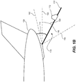
- FIG. 1B illustrates a side view of the rear of the vehicle with the refueling boom, in accordance with some examples.
- FIG. 1B illustrates refueling boom 110 coupled to fuselage 120.
- refueling boom 110 is coupled to fuselage 120 and, when in a stowed position, is latched to fuselage 120.
- Refueling boom 110 is, in certain examples, a "flying boom" configuration of an aerial refueling system.
- Refueling boom 110 includes refueling boom structure 116, hoist 114 coupled to refueling boom structure 116, and boom aerodynamic control surface 112 coupled to refueling boom structure 116.
- Refueling boom structure 116 includes a boom tip 118. Boom tip 118 is configured to be inserted into a refueling receptacle of an associated aircraft to deliver fuel to the associated aircraft.
- hoist 114 is configured to move refueling boom structure 116 while aircraft 100 is on the ground (e.g., has landed).
- Hoist 114 includes a cable configured to control movement of refueling boom structure 116.
- hoist 114 is configured to be operated in situations where boom aerodynamic control surface 112 does not generate enough aerodynamic lift to be able to lift and/or control refueling boom structure 116.
- the techniques described herein allow for usage of hoist 114 to deploy and stow refueling boom 110 in operating conditions where boom aerodynamic control surface 112 would not otherwise generate enough lift or provide sufficient control to deploy or stow refueling boom 110.
- hoist 114 includes a cable break monitor to determine whether the cable of hoist 114 is intact.
- hoist actuator Operation of hoist 114 is controlled, partially or fully, by a hoist actuator.
- the hoist actuator is operated in one of a plurality of different modes. Such modes include, for example, a tension mode, a hoisting mode, and a block mode.
- tension mode the hoist actuator is configured to maintain a baseline amount of tension on the cable of hoist 114.
- hoisting mode the cable of hoist 114 is operated to hoist (e.g., pull upward) refueling boom structure 116 towards fuselage 120.
- hoisting mode the tension imparted to the cable of hoist 114 is, in certain situations, significantly higher than the tension imparted in tension mode.
- refueling boom 110 In block mode, refueling boom 110 is in a stored position (e.g., is disposed underneath proximate to fuselage 120).
- the cable of hoist 114 in block mode, is locked.
- the hoist actuator transitions between different modes through operation of a clutch.
- Boom aerodynamic control surface 112 is coupled to a portion of refueling boom structure 116.
- Boom aerodynamic control surface 112 includes one or more wing structures and/or other aerodynamic features configured to generate lift when aircraft 100 is flying at speed.
- various portions of boom aerodynamic control surface 112 are configured to be manipulated (e.g., pivoted) to provide control over the flight characteristics of refueling boom structure 116.
- boom aerodynamic control surface 112 Operation of boom aerodynamic control surface 112 is controlled, partially or fully, by one or more aerodynamic actuators.
- boom aerodynamic control surface 112 includes both an elevator and one or more rudders.
- the aerodynamic actuators include an elevator actuator to control the elevator and one or more rudder actuators to control the one or more rudders.
- refueling boom 110 e.g., refueling boom structure 116 is configured to rotate over a range of angles. Such angles are referred to herein as boom pitch angle 166.
- Boom pitch angle 166 is determined from neutral angle 160.
- neutral angle 160 is parallel with a centerline of fuselage 120 or oriented in another manner.
- Refueling boom structure 116 is configured to rotate between upper angle limit 162 and lower angle limit 164.
- rotation of refueling boom structure 116 above neutral angle 160 is considered rotation in a negative angle while rotation of refueling boom structure 116 below neutral angle 160 (e.g., toward lower angle limit 164 such as when deployed) is considered rotation in a positive angle.
- boom pitch angle 166 is positive as refueling boom structure 116 is rotated below neutral angle 160.
- FIG. 2A illustrates a representation of various states of a refueling boom, in accordance with some examples.
- Refueling boom 110 is, in various examples, configured to operate in a plurality of different operating state modes.
- the various operating state modes include operating states for the various actuators of refueling boom 110.
- Such operating state modes include, for example, zero to fourth actuator state modes 206-214 as described in FIG. 2A .
- Controller 150 is configured to determine the operating state modes, as described herein.
- Zero to second actuator state modes 206-210 are a part of active mode group 202.
- Third and fourth actuator state modes 212 and 214 are a part of passive mode group 204.
- Refueling boom 110 transitions between the various actuator state modes depending on other conditions, as described herein. In certain examples, such operating conditions allows for a determination of whether conditions allow for operation of refueling boom 110 in a fly zone or a no fly zone. The fly zone and no fly zone are further described in FIG. 5
- FIG. 5 illustrates a representation of transitioning between fly and no fly zones, in accordance with some examples.
- FIG. 5 illustrates fly zone 502, no fly zone 504, and transition conditions 506 and 508.
- Fly zone 502 represents conditions appropriate for flying of refueling boom 110 by boom aerodynamic control surface 112.
- No fly zone 504 represents conditions inappropriate for flying of refueling boom 110 by boom aerodynamic control surface 112.
- no fly zone 504 is associated with conditions where boom aerodynamic control surface 112 lacks sufficient elevator authority to fly refueling boom 110 (e.g., toward fuselage 120).
- Controller 150 determines whether conditions indicate that aircraft 100 is within fly zone 502, no fly zone 504, or will transition between the two zones.
- Transition condition 506 allows for refueling boom 110 to transition from fly zone 502 to no fly zone 504.
- Transition condition 506, in certain examples, include conditions associated with measured dynamic pressure and/or airspeed, boom pitch angle 166, and/or commands issued by a user.
- Transition condition 508 allows for refueling boom 110 to transition from no fly zone 504 to fly zone 502.
- Transition condition 506, in certain examples, include conditions associated with measured dynamic pressure and/or airspeed, boom pitch angle 166, a cable rate of hoist 114 (e.g., speed of movement of the cable of hoist 114), and/or commands issued by a user.
- transition condition 506 requires a dynamic pressure less than a threshold dynamic pressure and a boom pitch angle 166 less than a threshold pitch angle while transition condition 508 requires a dynamic pressure greater than a threshold dynamic pressure, a boom pitch angle 166 greater than a threshold pitch angle, and a cable rate less than a threshold cable rate (e.g., indicating a cable tension less than a threshold tension).
- threshold dynamic pressure and threshold pitch angle are application specific (e.g., differs based on the platform such as the refueling boom and/or aircraft used) and, in certain situations, differ between transition condition 506 and transition condition 508.
- the dynamic pressure is determined by one or more pressure sensors of aircraft 100.
- Refueling boom 110 includes one or more sensors to determine boom pitch angle 166 and/or the cable rate.
- Other examples of aircraft 100 include other sensors to determine other parameters associated with fly zones and no fly zones.
- the threshold dynamic pressure is, in certain examples, in a slower or slowest part of the flight envelope and the threshold pitch angle is, in certain examples, above the aerial refueling envelope.
- User commands, for transition condition 506, include a command to stow refueling boom 110.
- transition conditions 506 and 508 include different absolute ranges or different ranges.
- user commands include a command to deploy refueling boom 110.
- zero actuator state mode 206 is a state for flying of refueling boom 110.
- boom aerodynamic control surface 112 is active and providing lift to control refueling boom 110.
- the pitch axis of refueling boom 110 is controlled by the elevator actuator while the roll axis of refueling boom 110 is controlled by the one or more rudder actuators.
- the hoist actuator is in tension mode.
- Refueling boom 110 is allowed to enter zero actuator state mode 206 (e.g., from first actuator state mode 208) if the following conditions are determined to be met: 1) that refueling boom 110 is within fly zone 502, 2) that the hoist actuator is in tension mode, 3) that the cable break monitor indicates that the hoist cable is intact, and/or 4) that a command was issued for refueling boom 110 to be flown.
- zero actuator state mode 206 e.g., from first actuator state mode 208 if the following conditions are determined to be met: 1) that refueling boom 110 is within fly zone 502, 2) that the hoist actuator is in tension mode, 3) that the cable break monitor indicates that the hoist cable is intact, and/or 4) that a command was issued for refueling boom 110 to be flown.
- First actuator state mode 208 is a state for transition of refueling boom 110 between zero actuator state mode 206 and second actuator state mode 210.
- first actuator state mode 208 is a handshake state to hand-off pitch control between the hoist and aerodynamic actuators (e.g., when transitioning between zero actuator state mode 206 and second actuator state mode 210).
- a clutch of hoist 114 is operated to allow for transition from second actuator state mode 210 to zero actuator state mode 206 or vice versa. Operation of the clutch allows for hoist 114 to transition between modes (e.g., transitioning between tension mode, hoisting mode, and/or block mode).
- modes in certain examples, are operated with different levels of cable tension and/or cable rates and operation of the clutch is needed in order to provide the appropriate gearing and/or torque required for operation in such modes.
- boom aerodynamic control surface 112 is inactive and hoist 114 is in tension mode.
- the pitch and roll axes of refueling boom 110 are controlled through damped trail behavior and not through one or more of the elevator actuator, the one or more rudder actuators, or the hoist actuator.
- Refueling boom 110 is allowed to enter first actuator state mode 208 from zero actuator state mode 206 if the following conditions are met: 1) that refueling boom 110 is within no fly zone 504, 2) that no command was issued for boom aerodynamic control surface 112 to be active (e.g., for refueling boom 110 to be flown), and/or 3) that the cable break monitor indicates that the hoist cable is intact.
- refueling boom 110 is allowed to enter first actuator state mode 208 from second actuator state mode 210 if the following conditions are met: 1) that refueling boom 110 is within fly zone 502, 2) that no command was issued for refueling boom 110 to be stowed or for the latch to be closed to stow refueling boom 110, and/or that the cable break monitor indicates that the hoist cable is intact.
- Refueling boom 110 is allowed to enter first actuator state mode 208 from passive mode group 204 if a command is issued to transition from passive mode group 204 to active mode group 202.
- boom aerodynamic control surface 112 is inactive and hoist 114 is in hoisting mode.
- the pitch axis of refueling boom 110 is controlled by the hoist actuator while the roll axis of refueling boom 110 is controlled by the damped trail behavior of refueling boom 110 (e.g., not actively controlled).
- Refueling boom 110 is allowed to enter second actuator state mode 210 from first actuator state mode 208 if the following conditions are met: 1) that refueling boom 110 is within fly zone 502, 2) that the elevator actuator indicates that it is not active, and/or 3) that a command was issued for hoist 114 to be in hoisting mode or for refueling boom 110 to transition from passive mode group 204 to active mode group 202.
- Third and fourth actuator state modes 212 and 214 are actuator states of passive mode group 204.
- Passive mode group 204 are actuator states used for when refueling boom 110 is not in use. As described herein, refueling boom 110 transitions between active mode group 202 and passive mode group 204 depending on whether refueling boom 110 is in use. Thus, when a command is issued to activate refueling boom 110 for use, refueling boom 110 transitions from passive mode group 204 to active mode group 202.
- third actuator state mode 212 boom aerodynamic control surface 112 is inactive and hoist 114 is in tension mode.
- the pitch and roll axes of refueling boom 110 are controlled by damped trail behavior and, thus, not actively controlled.
- refueling boom 110 enters third actuator state mode 212 if the following conditions are met: 1) a command was issued for refueling boom 110 to be in a faired state, and/or 2) a command was issued for refueling boom 110 to transition to passive mode group 204 from active mode group 202.
- fourth actuator state mode 214 boom aerodynamic control surface 112 is inactive and hoist 114 is in block mode.
- refueling boom 110 enters fourth actuator state mode 214 if the following conditions are met: 1) refueling boom 110 has been in a stowed state for a threshold period of time (e.g., 20 seconds or less) from when refueling boom 110 is in third actuator state mode 212, 2) a command was issued for refueling boom 110 to be in a block mode, and/or 3) a command was issued for refueling boom 110 to transition to passive mode group 204 from active mode group 202.
- a threshold period of time e.g. 20 seconds or less
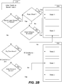
- FIG. 2B is a flowchart of a technique of determining the state of a refueling boom, in accordance with some examples. The technique of FIG. 2B is used to detect the appropriate actuator state of refueling boom 110 when refueling boom 110 is in operation.
- the technique described in FIG. 2B begins with a determination of the current actuator state in block 230.
- the initial condition of refueling 110 is determined.
- block 230 detects any reset of the actuator states (e.g., resulting from a reset of controller 150) and, in response, performs an initialization process where the appropriate mode and/or actuator state is selected.
- transition between active mode group 202 and passive mode group 204, or vice versa is also detected in block 230 and results in selection of the appropriate actuator state, as detailed in FIG. 2B .
- refueling boom 110 is indicating that it is in a stowed or faired condition is determined in block 232. If refueling boom 110 is in a stowed or faired condition, the technique proceeds to block 234 and passive mode group 204 is selected. Otherwise, the technique proceeds to block 238 and active mode group 202 is selected.
- flight conditions are then determined in block 238.
- flight conditions include, in certain examples, the fly zone status, the hoist actuator status, the elevator actuator status, the cable break monitor reading, and/or other sensor readings and factors used to determine the actuator state. Based on the various readings, the appropriate actuator state is selected. Accordingly, if conditions 242 (e.g., that hoist 114 is in tension mode and/or that the cable break monitor indicates that the cable is intact) are met, zero actuator state mode 206 is selected.
- conditions 244 e.g., that hoist 114 is not in tension mode or that cable break monitor indicates a break in the cable of hoist 114 are determined to be satisfied and the technique proceeds to block 240.
- FIG. 3 is a flowchart of a technique of utilizing a refueling boom, in accordance with some examples.
- FIG. 3 illustrates a technique of deploying the refueling boom from an initial stowed configuration.
- the refueling boom starts in a stowed position.
- the hoist is, in certain examples, in block mode and the boom is latched to the fuselage of the aircraft.
- the hoist actuator is in the fourth actuator state mode.
- a command to deploy the refueling boom is received.
- the boom After receiving the command, the boom is lifted off of the latch with the hoist in block 304.
- the hoist actuator is in the second actuator state mode.
- the hoist then lowers the refueling boom in block 306 while continuing to be in the second actuator state mode.
- the boom aerodynamic control surfaces are not active and the refueling boom is not being flown.
- Such conditions include measuring a dynamic pressure greater than a threshold dynamic pressure (indicating that airspeed is greater than a threshold airspeed), determining that the refueling boom is lowered enough so that the boom pitch angle is greater than a threshold pitch angle, and that the cable rate is less than a threshold cable rate.
- Such transition conditions are, thus, used to determine whether the refueling boom transitions from a no fly zone to a fly zone appropriate for flying the refueling boom.
- the technique returns to block 306 and the hoist continues to lower the refueling boom. If the conditions are determined to be met, the technique continues to block 310.
- the state mode of the hoist actuator is changed. In certain examples, the hoist actuator is changed to the first actuator state mode and the hoist actuator is set to a tension mode. A clutch is then operated to change the operation of the hoist to allow for flying of the refueling boom (e.g., in certain examples, the hoist actuator is required to be in tension mode before the refueling boom is flown).
- the boom aerodynamic control surfaces are activated in block 312.
- Activating the boom aerodynamic control surfaces includes, for example, engaging one or more wings and other aerodynamic surfaces of the refueling boom. When the aerodynamic surfaces are active, such surfaces generate lift for flying of the refueling boom.
- the hoist actuator is changed to the zero actuator state mode from the first actuator state mode when appropriate conditions are detected.
- the refueling boom is then flown in block 314 and control of the refueling boom is through that of the boom aerodynamic control surfaces instead of through the hoist.
- FIG. 4 is a flowchart of another technique of utilizing a refueling boom, in accordance with some examples.
- FIG. 4 illustrates a technique of stowing the refueling boom from an initially deployed configuration.
- the refueling boom is deployed.
- the refueling boom is deployed to provide refueling to other aircraft.
- the boom aerodynamic control surfaces are active to generate lift to control and fly the refueling boom.
- the hoist in such a state of the refueling boom, is not used to control the refueling boom.
- the refueling boom is flown towards the fuselage of the aircraft by, for example, aerodynamic lift generated by the boom aerodynamic control surfaces. Flying the refueling boom towards the fuselage is, in certain examples, performed to stow the refueling boom when not in use. While flying the refueling boom, the hoist actuator is in the zero actuator state mode.
- Such conditions include measuring a dynamic pressure less than a threshold dynamic pressure (indicating airspeed is less than a threshold airspeed) and/or determining that the refueling boom has been flown towards the fuselage enough such that the boom pitch angle is less than a threshold pitch angle.
- Such transition conditions are used to determine whether the refueling boom is transitioning from a fly zone to a no fly zone where the hoist is needed to retract the refueling boom.
- the technique returns to block 404 and the refueling boom continues to be flown towards the fuselage by the boom aerodynamic control surfaces. If the conditions are determined to be met, the technique continues to blocks 408 and 410.
- the boom aerodynamic control surfaces are deactivated.
- Deactivation of the boom aerodynamic control surfaces include, in some examples, deactivating or otherwise changing a configuration of the boom aerodynamic control surfaces so that less or no lift is generated.
- the actuator state mode of the hoist actuator is changed.
- the actuator state mode is first changed to the first actuator state mode and the hoist actuator is set to tension mode.
- the first actuator state mode is a handshake mode as described herein and, after changing to the first actuator state mode and allowing for the clutch of the hoist actuator to operate, the actuator state mode is changed to the second actuator state mode and the hoist actuator is set to a hoisting mode.
- the hoist actuator is changed to the second actuator state mode and, thus, the hoisting mode, in block 412.
- the refueling boom is raised with the hoist while the hoist actuator is in the second actuator state mode and in hoisting mode.
- the refueling boom is then raised to the fuselage and stowed proximate to the fuselage.
- the hoist is set to the third actuator state mode and, thus, in tension mode.
- the refueling boom is determined to be stowed and the hoist is set to the fourth actuator state mode and, thus, in block mode.
- FIGs. 3 and 4 allow for a refueling boom to be deployed and stowed with a hoist of the refueling boom in certain conditions (e.g., at certain airspeeds). As described herein, the hoist assists with certain stages of deployment and stowing of the refueling boom. When the refueling boom is fully deployed and in operation, boom aerodynamic control surfaces are used to control the refueling boom.
- FIG. 6A illustrates a flow chart of an example of a vehicle production and service methodology, in accordance with some examples.
- method 600 includes the specification and design 604 of vehicle 100 (e.g., an aircraft as shown in FIG. 1 ) and material procurement 606.
- vehicle 100 e.g., an aircraft as shown in FIG. 1
- material procurement 606 During production, component and subassembly manufacturing 608 and system integration 610 of vehicle 100 takes place. Thereafter, vehicle 100 goes through certification and delivery 612 in order to be placed in service 614. While in service by a customer, the vehicle 100 is scheduled for routine maintenance and service 616 (e.g., modification, reconfiguration, refurbishment, and so on).
- routine maintenance and service 616 e.g., modification, reconfiguration, refurbishment, and so on.
- each of the processes of method 600 is performed or carried out by a system integrator, a third party, and/or an operator (e.g., a customer).
- a system integrator includes any number of airplane manufacturers and major-system subcontractors;
- a third party includes any number of venders, subcontractors, and suppliers;
- an operator includes, in certain examples, an airline, leasing company, military entity, service organization, and so on.
- FIG. 6B illustrates a block diagram of an example of a vehicle, in accordance with some examples.
- the vehicle 100 e.g., an aircraft
- the vehicle 100 produced by method 600 includes airframe 618 with plurality of systems 620, and interior 622.
- systems 620 include one or more of propulsion system 624, electrical system 626, hydraulic system 628, and environmental system 630.
- propulsion system 624 e.g., an engine
- electrical system 626 e.g., electrical system 626
- hydraulic system 628 e.g., hydraulic system 628
- environmental system 630 e.g., a gas turbine, or a gas turbine, or a gas turbine.
- other systems are also included within vehicle 100.
- an aerospace example is shown, the principles of the embodiments disclosed herein is applicable to other industries, such as the automotive industry.
Landscapes
- Engineering & Computer Science (AREA)
- Aviation & Aerospace Engineering (AREA)
- Forklifts And Lifting Vehicles (AREA)
- Jib Cranes (AREA)
- Loading And Unloading Of Fuel Tanks Or Ships (AREA)
- Fluid-Pressure Circuits (AREA)
Abstract
Description
- This invention was made with Government support under contract number FA8625-11-C-6600 awarded by the Department of Defense. The Government has certain rights in this invention.
- Certain aerial refueling aircraft utilize an aerial refueling boom to perform refueling. The refueling boom, when in the stowed position, is latched to the fuselage of the aircraft. Typically, when a deployment of the refueling boom is commanded, a boom aerodynamic control surface of the refueling boom generates aerodynamic lift to raise the refueling boom off a latch. The latch is then opened once the refueling boom is lifted, before the refueling boom is then lowered. The boom aerodynamic control surface then provides aerodynamic control to fly the refueling boom away from the fuselage. Conversely, when a stow of the refueling boom is commanded, the boom aerodynamic control surface flies the refueling boom up to the fuselage, the latch is closed and the refueling boom is accordingly coupled to the fuselage.
- Described are methods and systems for deploying and stowing a refueling boom. In a certain example, the technique includes lowering, while a hoist of a refueling boom is in a second actuator state mode, a refueling boom structure of the refueling boom with the hoist while a boom aerodynamic control surface of the refueling boom is deactivated, determining that first transition conditions have been met, switching the hoist from the second actuator state mode to a first actuator state mode, and activating the boom aerodynamic control surface.
- In another example, the technique includes flying a refueling boom towards a fuselage of an aircraft while a hoist of the refueling boom is in a zero actuator state mode, determining that second transition conditions have been met, switching the hoist from the zero actuator state mode to a first actuator state mode, and raising a refueling boom structure of the refueling boom with the hoist.
- Illustrative, non-exclusive examples of inventive features according to present disclosure are described herein. These and other examples are described further below with reference to figures.
- The disclosure may best be understood by reference to the following description taken in conjunction with the accompanying drawings, which illustrate various examples.
-
FIG. 1A illustrates a vehicle with a refueling boom, in accordance with some examples. -
FIG. 1B illustrates a side view of the rear of the vehicle with the refueling boom, in accordance with some examples. -
FIG. 2A illustrates a representation of various states of a refueling boom, in accordance with some examples. -
FIG. 2B is a flowchart of a technique of determining the state of a refueling boom, in accordance with some examples. -
FIG. 3 is a flowchart of a technique of utilizing a refueling boom, in accordance with some examples. -
FIG. 4 is a flowchart of another technique of utilizing a refueling boom, in accordance with some examples. -
FIG. 5 illustrates a representation of transitioning between fly and no fly zones, in accordance with some examples. -
FIG. 6A illustrates a flow chart of an example of an aircraft production and service methodology, in accordance with some examples. -
FIG. 6B illustrates a block diagram of an example of a vehicle, in accordance with some examples. - In the following description, numerous specific details are set forth in order to provide a thorough understanding of the presented concepts. The presented concepts may be practiced without some, or all, of these specific details. In other instances, well known process operations have not been described in detail to avoid unnecessarily obscuring the described concepts. While some concepts will be described with the specific examples, it will be understood that these examples are not intended to be limiting.
- Described herein are control techniques for a refueling boom. The refueling boom structure, in certain examples, includes a boom aerodynamic control surface which is deactivated while the hoist is in a second actuator state mode. The refueling boom control techniques include lowering a refueling boom structure with a hoist while the hoist is in the second actuator state mode, determining that first transition conditions have been met, switching the hoist from the second actuator state mode to a first actuator state mode, and activating the boom aerodynamic control surface after the hoist is in the first actuator state mode.
- In certain examples, aerial refueling aircrafts include an aerial refueling boom. The aerial refueling boom is located along the fuselage of the aircraft in certain examples and is stowed by being latched to the fuselage of the aircraft. In such configurations, when deployment of the refueling boom is commanded, a boom aerodynamic control surface (e.g., a boom elevator) of the refueling boom generates aerodynamic lift to raise the refueling boom off a latch. The latch is then opened once the refueling boom is lifted, before the refueling boom is then lowered. The boom aerodynamic control surface then provides control to fly the refueling boom away from the fuselage. When a stow of the refueling boom is commanded, the boom aerodynamic control surface flies the refueling boom up to the fuselage and the refueling boom is accordingly latched to the fuselage.
- In certain examples, a single command stow and deploy throughout the entire aerial refueling envelope improves usability and is required in certain applications. However, at slow airspeeds, the boom aerodynamic control surface does not generate enough aerodynamic lift to lift the boom up above the latch. In examples described herein, in this region of the flight envelope, the hoist is used to lift the boom off the latch instead.
- In certain such examples, the techniques described herein are used as a retrofit or update to existing systems. Certain existing systems include hoists that are not originally intended to be used in the deploying the refueling boom. In certain such systems, to prevent damage to various components of the system, it is essential that both the hoist actuator (controlling movement of the hoist) and the aerodynamic actuator (controlling movement of the boom aerodynamic control surface) are not active at the same. The techniques described herein allow for coordination and collaborative efforts between the two dissimilar actuators (e.g., the hoist actuator and the elevator actuator) to allow for single button stow and deploy throughout the aerial refueling envelope.
- An example of a vehicle equipped with refueling boom is shown in
FIG. 1A. FIG. 1A illustrates a vehicle with a refueling boom, in accordance with some examples.FIG. 1A illustratesvehicle 100 that is a fixed wing aircraft, but other examples include other structures (e.g., helicopters, variable wing aircraft, short takeoff and landing aircraft, spacecraft, drones, and other such vehicles). -
Vehicle 100 includesfuselage 120,wings 140, andaircraft propulsors 130. Each ofaircraft propulsors 130 are coupled to arespective wing 140.Wings 140 are coupled tofuselage 120.Vehicle 100 further includes refuelingboom 110 coupled to a portion of fuselage 120 (e.g., an aft fuselage 120). Further details of refuelingboom 110 are shown and described inFIG. 1B . -
Refueling boom 110 is controlled bycontroller 150.Controller 150 includes, in various examples, a memory, a processor, and other logic device components.Controller 150 receives data, performs calculations, and provides outputs (e.g., control instructions) to various other portions ofvehicle 100.Controller 150 is communicatively coupled torefueling boom 110 throughcommunication network 154. In certain examples,communication network 154 is any type of wired and/or wireless network that communicates data and/or power to and fromcontroller 150.Controller 150 is also coupled tosensors 152 viacommunication network 154.Sensors 152 include air speed, air pressure (e.g., dynamic pressure), altitude, and other such sensors to measure readings associated with operation ofvehicle 100. In certain examples,sensors 152 also include an additional hoist cable break monitor configured to determine whether the cable of hoist 114 (described inFIG. 1B ) is broken.Controller 150, in various examples, is configured to determine parameters and/or cause various systems to perform the operations described herein. -
FIG. 1B illustrates a side view of the rear of the vehicle with the refueling boom, in accordance with some examples.FIG. 1B illustratesrefueling boom 110 coupled tofuselage 120. In various examples,refueling boom 110 is coupled tofuselage 120 and, when in a stowed position, is latched tofuselage 120.Refueling boom 110 is, in certain examples, a "flying boom" configuration of an aerial refueling system. -
Refueling boom 110 includesrefueling boom structure 116, hoist 114 coupled torefueling boom structure 116, and boomaerodynamic control surface 112 coupled torefueling boom structure 116. Refuelingboom structure 116 includes aboom tip 118.Boom tip 118 is configured to be inserted into a refueling receptacle of an associated aircraft to deliver fuel to the associated aircraft. - In certain examples, hoist 114 is configured to move
refueling boom structure 116 whileaircraft 100 is on the ground (e.g., has landed). Hoist 114 includes a cable configured to control movement ofrefueling boom structure 116. In certain examples described herein, hoist 114 is configured to be operated in situations where boomaerodynamic control surface 112 does not generate enough aerodynamic lift to be able to lift and/or controlrefueling boom structure 116. Thus, the techniques described herein allow for usage of hoist 114 to deploy andstow refueling boom 110 in operating conditions where boomaerodynamic control surface 112 would not otherwise generate enough lift or provide sufficient control to deploy orstow refueling boom 110. In certain examples, hoist 114 includes a cable break monitor to determine whether the cable of hoist 114 is intact. - Operation of hoist 114 is controlled, partially or fully, by a hoist actuator. The hoist actuator is operated in one of a plurality of different modes. Such modes include, for example, a tension mode, a hoisting mode, and a block mode. In tension mode, the hoist actuator is configured to maintain a baseline amount of tension on the cable of hoist 114. In hoisting mode, the cable of hoist 114 is operated to hoist (e.g., pull upward)
refueling boom structure 116 towardsfuselage 120. In hoisting mode, the tension imparted to the cable of hoist 114 is, in certain situations, significantly higher than the tension imparted in tension mode. In block mode,refueling boom 110 is in a stored position (e.g., is disposed underneath proximate to fuselage 120). The cable of hoist 114, in block mode, is locked. In various examples, the hoist actuator transitions between different modes through operation of a clutch. - Boom
aerodynamic control surface 112 is coupled to a portion ofrefueling boom structure 116. Boomaerodynamic control surface 112 includes one or more wing structures and/or other aerodynamic features configured to generate lift whenaircraft 100 is flying at speed. In certain examples, various portions of boomaerodynamic control surface 112 are configured to be manipulated (e.g., pivoted) to provide control over the flight characteristics ofrefueling boom structure 116. - Operation of boom
aerodynamic control surface 112 is controlled, partially or fully, by one or more aerodynamic actuators. In certain examples, boomaerodynamic control surface 112 includes both an elevator and one or more rudders. In such a configuration, the aerodynamic actuators include an elevator actuator to control the elevator and one or more rudder actuators to control the one or more rudders. - In various examples, refueling boom 110 (e.g., refueling boom structure 116) is configured to rotate over a range of angles. Such angles are referred to herein as
boom pitch angle 166.Boom pitch angle 166, as described herein, is determined fromneutral angle 160. In certain examples,neutral angle 160 is parallel with a centerline offuselage 120 or oriented in another manner. Refuelingboom structure 116, as described inFIG. 1B , is configured to rotate betweenupper angle limit 162 andlower angle limit 164. In various examples, rotation ofrefueling boom structure 116 above neutral angle 160 (e.g., towardupper angle limit 162 such as when in a stored position) is considered rotation in a negative angle while rotation ofrefueling boom structure 116 below neutral angle 160 (e.g., towardlower angle limit 164 such as when deployed) is considered rotation in a positive angle. As shown inFIG. 1B ,boom pitch angle 166 is positive asrefueling boom structure 116 is rotated belowneutral angle 160. -
FIG. 2A illustrates a representation of various states of a refueling boom, in accordance with some examples.Refueling boom 110 is, in various examples, configured to operate in a plurality of different operating state modes. The various operating state modes include operating states for the various actuators ofrefueling boom 110. Such operating state modes include, for example, zero to fourth actuator state modes 206-214 as described inFIG. 2A .Controller 150 is configured to determine the operating state modes, as described herein. - Zero to second actuator state modes 206-210 are a part of
active mode group 202. Third and fourthactuator state modes passive mode group 204.Refueling boom 110 transitions between the various actuator state modes depending on other conditions, as described herein. In certain examples, such operating conditions allows for a determination of whether conditions allow for operation ofrefueling boom 110 in a fly zone or a no fly zone. The fly zone and no fly zone are further described inFIG. 5 -
FIG. 5 illustrates a representation of transitioning between fly and no fly zones, in accordance with some examples.FIG. 5 illustratesfly zone 502, nofly zone 504, andtransition conditions Fly zone 502 represents conditions appropriate for flying ofrefueling boom 110 by boomaerodynamic control surface 112. Nofly zone 504 represents conditions inappropriate for flying ofrefueling boom 110 by boomaerodynamic control surface 112. Thus, for example, nofly zone 504 is associated with conditions where boomaerodynamic control surface 112 lacks sufficient elevator authority to fly refueling boom 110 (e.g., toward fuselage 120). - Transition between
fly zone 502 and nofly zone 504, and vice versa, are allowed iftransitions conditions Controller 150 determines whether conditions indicate thataircraft 100 is withinfly zone 502, nofly zone 504, or will transition between the two zones. -
Transition condition 506 allows forrefueling boom 110 to transition fromfly zone 502 to nofly zone 504.Transition condition 506, in certain examples, include conditions associated with measured dynamic pressure and/or airspeed,boom pitch angle 166, and/or commands issued by a user.Transition condition 508 allows forrefueling boom 110 to transition from nofly zone 504 to flyzone 502.Transition condition 506, in certain examples, include conditions associated with measured dynamic pressure and/or airspeed,boom pitch angle 166, a cable rate of hoist 114 (e.g., speed of movement of the cable of hoist 114), and/or commands issued by a user. - Thus, for example,
transition condition 506 requires a dynamic pressure less than a threshold dynamic pressure and aboom pitch angle 166 less than a threshold pitch angle whiletransition condition 508 requires a dynamic pressure greater than a threshold dynamic pressure, aboom pitch angle 166 greater than a threshold pitch angle, and a cable rate less than a threshold cable rate (e.g., indicating a cable tension less than a threshold tension). Such threshold dynamic pressure and threshold pitch angle are application specific (e.g., differs based on the platform such as the refueling boom and/or aircraft used) and, in certain situations, differ betweentransition condition 506 andtransition condition 508. - The dynamic pressure is determined by one or more pressure sensors of
aircraft 100.Refueling boom 110 includes one or more sensors to determineboom pitch angle 166 and/or the cable rate. Other examples ofaircraft 100 include other sensors to determine other parameters associated with fly zones and no fly zones. - In certain examples, for
transition conditions transition condition 506, include a command tostow refueling boom 110. In various examples,transition conditions refueling boom 110. - Referring back to
FIG. 2A , zeroactuator state mode 206 is a state for flying ofrefueling boom 110. Thus, in zeroactuator state mode 206, boomaerodynamic control surface 112 is active and providing lift to controlrefueling boom 110. The pitch axis ofrefueling boom 110 is controlled by the elevator actuator while the roll axis ofrefueling boom 110 is controlled by the one or more rudder actuators. In zeroactuator state mode 206, the hoist actuator is in tension mode. -
Refueling boom 110 is allowed to enter zero actuator state mode 206 (e.g., from first actuator state mode 208) if the following conditions are determined to be met: 1) thatrefueling boom 110 is withinfly zone 502, 2) that the hoist actuator is in tension mode, 3) that the cable break monitor indicates that the hoist cable is intact, and/or 4) that a command was issued forrefueling boom 110 to be flown. - First
actuator state mode 208 is a state for transition ofrefueling boom 110 between zeroactuator state mode 206 and secondactuator state mode 210. In various examples, firstactuator state mode 208 is a handshake state to hand-off pitch control between the hoist and aerodynamic actuators (e.g., when transitioning between zeroactuator state mode 206 and second actuator state mode 210). As such, in certain examples while in firstactuator state mode 208, a clutch of hoist 114 is operated to allow for transition from secondactuator state mode 210 to zeroactuator state mode 206 or vice versa. Operation of the clutch allows for hoist 114 to transition between modes (e.g., transitioning between tension mode, hoisting mode, and/or block mode). Such modes, in certain examples, are operated with different levels of cable tension and/or cable rates and operation of the clutch is needed in order to provide the appropriate gearing and/or torque required for operation in such modes. - In first
actuator state mode 208, boomaerodynamic control surface 112 is inactive and hoist 114 is in tension mode. The pitch and roll axes ofrefueling boom 110 are controlled through damped trail behavior and not through one or more of the elevator actuator, the one or more rudder actuators, or the hoist actuator. -
Refueling boom 110 is allowed to enter firstactuator state mode 208 from zeroactuator state mode 206 if the following conditions are met: 1) thatrefueling boom 110 is within nofly zone 504, 2) that no command was issued for boomaerodynamic control surface 112 to be active (e.g., forrefueling boom 110 to be flown), and/or 3) that the cable break monitor indicates that the hoist cable is intact. Furthermore,refueling boom 110 is allowed to enter firstactuator state mode 208 from secondactuator state mode 210 if the following conditions are met: 1) thatrefueling boom 110 is withinfly zone 502, 2) that no command was issued forrefueling boom 110 to be stowed or for the latch to be closed tostow refueling boom 110, and/or that the cable break monitor indicates that the hoist cable is intact.Refueling boom 110 is allowed to enter firstactuator state mode 208 frompassive mode group 204 if a command is issued to transition frompassive mode group 204 toactive mode group 202. - In second
actuator state mode 210, boomaerodynamic control surface 112 is inactive and hoist 114 is in hoisting mode. The pitch axis ofrefueling boom 110 is controlled by the hoist actuator while the roll axis ofrefueling boom 110 is controlled by the damped trail behavior of refueling boom 110 (e.g., not actively controlled). -
Refueling boom 110 is allowed to enter secondactuator state mode 210 from firstactuator state mode 208 if the following conditions are met: 1) thatrefueling boom 110 is withinfly zone 502, 2) that the elevator actuator indicates that it is not active, and/or 3) that a command was issued for hoist 114 to be in hoisting mode or forrefueling boom 110 to transition frompassive mode group 204 toactive mode group 202. - Third and fourth
actuator state modes passive mode group 204.Passive mode group 204 are actuator states used for when refuelingboom 110 is not in use. As described herein,refueling boom 110 transitions betweenactive mode group 202 andpassive mode group 204 depending on whetherrefueling boom 110 is in use. Thus, when a command is issued to activaterefueling boom 110 for use,refueling boom 110 transitions frompassive mode group 204 toactive mode group 202. - In third
actuator state mode 212, boomaerodynamic control surface 112 is inactive and hoist 114 is in tension mode. The pitch and roll axes ofrefueling boom 110 are controlled by damped trail behavior and, thus, not actively controlled. When inpassive mode group 204,refueling boom 110 enters thirdactuator state mode 212 if the following conditions are met: 1) a command was issued forrefueling boom 110 to be in a faired state, and/or 2) a command was issued forrefueling boom 110 to transition topassive mode group 204 fromactive mode group 202. - In fourth
actuator state mode 214, boomaerodynamic control surface 112 is inactive and hoist 114 is in block mode. When inpassive mode group 204,refueling boom 110 enters fourthactuator state mode 214 if the following conditions are met: 1)refueling boom 110 has been in a stowed state for a threshold period of time (e.g., 20 seconds or less) from when refuelingboom 110 is in thirdactuator state mode 212, 2) a command was issued forrefueling boom 110 to be in a block mode, and/or 3) a command was issued forrefueling boom 110 to transition topassive mode group 204 fromactive mode group 202. - Various techniques of determining the appropriate actuator state mode are described herein.
FIG. 2B is a flowchart of a technique of determining the state of a refueling boom, in accordance with some examples. The technique ofFIG. 2B is used to detect the appropriate actuator state ofrefueling boom 110 when refuelingboom 110 is in operation. - In various examples, the technique described in
FIG. 2B begins with a determination of the current actuator state inblock 230. Inblock 230, the initial condition of refueling 110 is determined. Thus, for example, block 230 detects any reset of the actuator states (e.g., resulting from a reset of controller 150) and, in response, performs an initialization process where the appropriate mode and/or actuator state is selected. Additionally, transition betweenactive mode group 202 andpassive mode group 204, or vice versa, is also detected inblock 230 and results in selection of the appropriate actuator state, as detailed inFIG. 2B . - After initial conditions are determined in
block 230, whetherrefueling boom 110 is indicating that it is in a stowed or faired condition is determined inblock 232. Ifrefueling boom 110 is in a stowed or faired condition, the technique proceeds to block 234 andpassive mode group 204 is selected. Otherwise, the technique proceeds to block 238 andactive mode group 202 is selected. - In
block 234, a determination is made as to whetherrefueling boom 110 has been reset. If a reset has been performed,refueling boom 110 will, in certain examples, select in fourthactuator state mode 214. Otherwise, the state of the hoist actuator, as determined inblock 236, is used to select the appropriate actuator state. Thus, for example, if hoist 114 is inactive (e.g., in a block mode),refueling boom 110 initializes in fourthactuator state mode 214. Otherwise,refueling boom 110, in certain examples, initializes in thirdactuator state mode 212. - If
active mode group 202 is selected inblock 232, flight conditions are then determined inblock 238. Such flight conditions include, in certain examples, the fly zone status, the hoist actuator status, the elevator actuator status, the cable break monitor reading, and/or other sensor readings and factors used to determine the actuator state. Based on the various readings, the appropriate actuator state is selected. Accordingly, if conditions 242 (e.g., that hoist 114 is in tension mode and/or that the cable break monitor indicates that the cable is intact) are met, zeroactuator state mode 206 is selected. - Otherwise, conditions 244 (e.g., that hoist 114 is not in tension mode or that cable break monitor indicates a break in the cable of hoist 114) are determined to be satisfied and the technique proceeds to block 240. In
block 240, a determination is made of whether the hoist actuator is active. If the hoist actuator is active, secondactuator state mode 210 is selected. Otherwise, firstactuator state mode 208 is selected. -
FIG. 3 is a flowchart of a technique of utilizing a refueling boom, in accordance with some examples.FIG. 3 illustrates a technique of deploying the refueling boom from an initial stowed configuration. Inblock 302 ofFIG. 3 , the refueling boom starts in a stowed position. While in the stowed position, the hoist is, in certain examples, in block mode and the boom is latched to the fuselage of the aircraft. As such, the hoist actuator is in the fourth actuator state mode. While in the block mode inblock 302, a command to deploy the refueling boom is received. - After receiving the command, the boom is lifted off of the latch with the hoist in
block 304. The hoist actuator is in the second actuator state mode. The hoist then lowers the refueling boom inblock 306 while continuing to be in the second actuator state mode. In blocks 304 and 306, the boom aerodynamic control surfaces are not active and the refueling boom is not being flown. - While lowering the refueling boom with the hoist, a determination is made of whether conditions to transition the state mode of the hoist are met, in
block 308. Such conditions, in certain examples, include measuring a dynamic pressure greater than a threshold dynamic pressure (indicating that airspeed is greater than a threshold airspeed), determining that the refueling boom is lowered enough so that the boom pitch angle is greater than a threshold pitch angle, and that the cable rate is less than a threshold cable rate. Such transition conditions are, thus, used to determine whether the refueling boom transitions from a no fly zone to a fly zone appropriate for flying the refueling boom. - If it is determined that the conditions are not met, the technique returns to block 306 and the hoist continues to lower the refueling boom. If the conditions are determined to be met, the technique continues to block 310. In
block 310, the state mode of the hoist actuator is changed. In certain examples, the hoist actuator is changed to the first actuator state mode and the hoist actuator is set to a tension mode. A clutch is then operated to change the operation of the hoist to allow for flying of the refueling boom (e.g., in certain examples, the hoist actuator is required to be in tension mode before the refueling boom is flown). - Once the hoist is set to tension mode, the boom aerodynamic control surfaces are activated in
block 312. Activating the boom aerodynamic control surfaces includes, for example, engaging one or more wings and other aerodynamic surfaces of the refueling boom. When the aerodynamic surfaces are active, such surfaces generate lift for flying of the refueling boom. Upon activation of the boom aerodynamic control surfaces, the hoist actuator is changed to the zero actuator state mode from the first actuator state mode when appropriate conditions are detected. The refueling boom is then flown inblock 314 and control of the refueling boom is through that of the boom aerodynamic control surfaces instead of through the hoist. -
FIG. 4 is a flowchart of another technique of utilizing a refueling boom, in accordance with some examples.FIG. 4 illustrates a technique of stowing the refueling boom from an initially deployed configuration. Inblock 402, the refueling boom is deployed. In certain examples, the refueling boom is deployed to provide refueling to other aircraft. When the refueling boom is deployed, the boom aerodynamic control surfaces are active to generate lift to control and fly the refueling boom. The hoist, in such a state of the refueling boom, is not used to control the refueling boom. - In
block 404, the refueling boom is flown towards the fuselage of the aircraft by, for example, aerodynamic lift generated by the boom aerodynamic control surfaces. Flying the refueling boom towards the fuselage is, in certain examples, performed to stow the refueling boom when not in use. While flying the refueling boom, the hoist actuator is in the zero actuator state mode. - While flying the refueling boom toward the fuselage, a determination is made as to whether conditions to transition the refueling boom to hoist control are met, in block 406 (e.g., to transition to the hoist retracting the refueling boom instead of flying the refueling boom towards the fuselage). Such conditions, in certain examples, include measuring a dynamic pressure less than a threshold dynamic pressure (indicating airspeed is less than a threshold airspeed) and/or determining that the refueling boom has been flown towards the fuselage enough such that the boom pitch angle is less than a threshold pitch angle. Such transition conditions are used to determine whether the refueling boom is transitioning from a fly zone to a no fly zone where the hoist is needed to retract the refueling boom.
- If it is determined that the conditions are not met, the technique returns to block 404 and the refueling boom continues to be flown towards the fuselage by the boom aerodynamic control surfaces. If the conditions are determined to be met, the technique continues to
blocks - In
block 408, the boom aerodynamic control surfaces are deactivated. Deactivation of the boom aerodynamic control surfaces include, in some examples, deactivating or otherwise changing a configuration of the boom aerodynamic control surfaces so that less or no lift is generated. - In
block 410, the actuator state mode of the hoist actuator is changed. In various examples, the actuator state mode is first changed to the first actuator state mode and the hoist actuator is set to tension mode. In certain additional examples, the first actuator state mode is a handshake mode as described herein and, after changing to the first actuator state mode and allowing for the clutch of the hoist actuator to operate, the actuator state mode is changed to the second actuator state mode and the hoist actuator is set to a hoisting mode. In other examples, the hoist actuator is changed to the second actuator state mode and, thus, the hoisting mode, inblock 412. - In
block 412, the refueling boom is raised with the hoist while the hoist actuator is in the second actuator state mode and in hoisting mode. The refueling boom is then raised to the fuselage and stowed proximate to the fuselage. Once it is indicated that the refueling boom is stowed, the hoist is set to the third actuator state mode and, thus, in tension mode. Past a threshold period of time, inblock 414, the refueling boom is determined to be stowed and the hoist is set to the fourth actuator state mode and, thus, in block mode. - The techniques of
FIGs. 3 and4 allow for a refueling boom to be deployed and stowed with a hoist of the refueling boom in certain conditions (e.g., at certain airspeeds). As described herein, the hoist assists with certain stages of deployment and stowing of the refueling boom. When the refueling boom is fully deployed and in operation, boom aerodynamic control surfaces are used to control the refueling boom. - While the systems, apparatus, and methods disclosed above have been described with reference to airplanes and the aerospace industry, it will be appreciated that the examples disclosed herein is applicable to other contexts as well, such as automotive, railroad, and other mechanical and vehicular contexts. Accordingly, examples of the disclosure is described in the context of an airplane manufacturing and
service method 600 as shown inFIG. 6A andvehicle 100 as shown inFIG. 6B in applicable to such other contexts. -
FIG. 6A illustrates a flow chart of an example of a vehicle production and service methodology, in accordance with some examples. In some examples, during pre-production,method 600 includes the specification anddesign 604 of vehicle 100 (e.g., an aircraft as shown inFIG. 1 ) andmaterial procurement 606. During production, component andsubassembly manufacturing 608 andsystem integration 610 ofvehicle 100 takes place. Thereafter,vehicle 100 goes through certification anddelivery 612 in order to be placed inservice 614. While in service by a customer, thevehicle 100 is scheduled for routine maintenance and service 616 (e.g., modification, reconfiguration, refurbishment, and so on). - In certain examples, each of the processes of
method 600 is performed or carried out by a system integrator, a third party, and/or an operator (e.g., a customer). For the purposes of this description, a system integrator includes any number of airplane manufacturers and major-system subcontractors; a third party includes any number of venders, subcontractors, and suppliers; and an operator includes, in certain examples, an airline, leasing company, military entity, service organization, and so on. -
FIG. 6B illustrates a block diagram of an example of a vehicle, in accordance with some examples. As shown inFIG. 6B , the vehicle 100 (e.g., an aircraft) produced bymethod 600 includesairframe 618 with plurality ofsystems 620, andinterior 622. Examples ofsystems 620 include one or more ofpropulsion system 624,electrical system 626,hydraulic system 628, andenvironmental system 630. In various examples, other systems are also included withinvehicle 100. Although an aerospace example is shown, the principles of the embodiments disclosed herein is applicable to other industries, such as the automotive industry. - Further, the disclosure includes examples according to the following clauses:
-
Clause 1. Anaircraft 100, comprising:- a
refueling boom 110 comprising:- a
refueling boom structure 116; - a hoist 114; and
- a boom
aerodynamic control surface 112; and
- a
- a
controller 150 configured to cause therefueling boom 110 to perform operations comprising:- lowering 306, while the hoist 114 is in a second
actuator state mode 210, therefueling boom structure 116 with the hoist 114 while the boomaerodynamic control surface 112 is deactivated; - determining 308 that first transition conditions have been met;
- switching 310 the hoist 114 from the second
actuator state mode 210 to a firstactuator state mode 208; and - activating 312 the boom
aerodynamic control surface 112.
- lowering 306, while the hoist 114 is in a second
- a
-
Clause 2. Theaircraft 100 ofclause 1, wherein the operations further comprise:
flying 314 therefueling boom 110 after the activating 312 the boomaerodynamic control surface 112. -
Clause 3. Theaircraft 100 ofclause 2, wherein the flying 314 therefueling boom 110 comprises switching the hoist 114 to a zeroactuator state mode 206. -
Clause 4. Theaircraft 100 of clauses 2-3, wherein the flying 314 therefueling boom 110 is based on received user instructions. - Clause 5. The
aircraft 100 ofclause 3, wherein the switching 310 to the firstactuator state mode 208 comprises operating a clutch of the hoist 114 to allow a transition from the secondactuator state mode 210 to the zeroactuator state mode 206. - Clause 6. The
aircraft 100 of clauses 1-5, wherein the first transition conditions comprise:- a
boom pitch angle 166 greater than a first threshold angle; and - a hoist cable rate less than a first threshold rate.
- a
- Clause 7. The
aircraft 100 of clause 6, wherein theboom pitch angle 166 is determined from aneutral angle 160. - Clause 8. The
aircraft 100 of clauses 6-7, wherein the first transition conditions further comprise:
an aircraft dynamic pressure greater than a first threshold dynamic pressure. - Clause 9. The
aircraft 100 of clause 8, further comprising:
adynamic pressure sensor 152 configured to measure the aircraft dynamic pressure. - Clause 10. The
aircraft 100 of clauses 1-9, wherein the operations further comprise:
lifting 304 therefueling boom structure 116 from a stowed position with the hoist 114. - Clause 11. The
aircraft 100 of clause 10, wherein the lifting 304 therefueling boom structure 116 is with the hoist 114 is in a fourthactuator state mode 214. - Clause 12. The
aircraft 100 of clauses 1-11, wherein the operations are performed while theaircraft 100 is in flight. - Clause 13. The
aircraft 100 of clauses 1-12, wherein the operations further comprise:- flying 404 the
refueling boom 110 towards afuselage 120 of theaircraft 100 while the hoist 114 is in a zeroactuator state mode 206; - determining 406 that second transition conditions have been met;
- switching 410 the hoist 114 from the zero
actuator state mode 206 to a firstactuator state mode 208; and - raising 412 the
refueling boom structure 116 with the hoist 114.
- flying 404 the
- Clause 14. The
aircraft 100 of clause 13, wherein the raising 412 therefueling boom structure 116 comprises switching the hoist 114 to a secondactuator state mode 210 from the firstactuator state mode 208. - Clause 15. The
aircraft 100 of clause 14, wherein the switching 410 to the firstactuator state mode 208 comprises operating a clutch of the hoist 114 to allow for a transition from the zeroactuator state mode 206 to the secondactuator state mode 210. - Clause 16. The
aircraft 100 of clauses 13-15, wherein the second transition conditions comprise aboom pitch angle 166 less than a second threshold angle. - Clause 17. The
aircraft 100 of clause 16, wherein the first transition conditions further comprise:
an aircraft dynamic pressure less than a second threshold dynamic pressure. - Clause 18. The
Aircraft 100 of clauses 13-17, wherein the operations further comprise:
deactivating 408 the boomaerodynamic control surface 112. - Clause 19. The
aircraft 100 of clauses 13-18, wherein the operations further comprise:
stowing 414 therefueling boom 110. - Clause 20. The
aircraft 100 of clause 19, wherein the stowing 414 therefueling boom 110 is with the hoist 114 in a fourthactuator state mode 214. - Clause 21. A method comprising:
- lowering 306, while a hoist 114 of a
refueling boom 110 is in a secondactuator state mode 210, arefueling boom structure 116 of therefueling boom 110 with the hoist 114 while a boomaerodynamic control surface 112 of therefueling boom 110 is deactivated; - determining 308 that first transition conditions have been met;
- switching 310 the hoist 114 from the second
actuator state mode 210 to a firstactuator state mode 208; and - activating 312 the boom
aerodynamic control surface 112.
- lowering 306, while a hoist 114 of a
- Clause 22. The method of clause 21, further comprising:
flying 314 therefueling boom 110 after the activating 312 the boomaerodynamic control surface 112. - Clause 23. The method of clause 22, wherein the flying 314 the
refueling boom 110 comprises switching the hoist 114 to a zeroactuator state mode 206. - Clause 24. The method of clauses 22-23, wherein the flying 314 the
refueling boom 110 is based on received user instructions. - Clause 25. The method of clauses 23-24, wherein the switching 310 to the first
actuator state mode 208 comprises operating a clutch of the hoist 114 to allow a transition from the secondactuator state mode 210 to the zeroactuator state mode 206. - Clause 26. The method of clauses 21-25, wherein the first transition conditions comprise:
- a
boom pitch angle 166 greater than a first threshold angle; and - a hoist cable rate less than a first threshold rate.
- a
- Clause 27. The method of clause 26, wherein the
boom pitch angle 166 is determined from aneutral angle 160. - Clause 28. The method of clauses 26-27, wherein the first transition conditions further comprise:
an aircraft dynamic pressure greater than a first threshold dynamic pressure. - Clause 29. The method of clause 28, wherein the aircraft dynamic pressure is measured by a
dynamic pressure sensor 152. - Clause 30. The method of clauses 21-29, further comprising:
lifting 304 therefueling boom structure 116 from a stowed position with the hoist 114, wherein the lifting 304 therefueling boom structure 116 is with the hoist 114 is in a fourthactuator state mode 214. - Clause 31. A method comprising:
- flying 404 a
refueling boom 110 towards afuselage 120 of anaircraft 100 while a hoist 114 of therefueling boom 110 is in a zeroactuator state mode 206; - determining 406 that second transition conditions have been met;
- switching 410 the hoist 114 from the zero
actuator state mode 206 to a firstactuator state mode 208; and - raising 412 a
refueling boom structure 116 of therefueling boom 110 with the hoist 114.
- flying 404 a
- Clause 32. The method of clause 31, wherein the raising 412 the
refueling boom structure 116 comprises switching the hoist 114 to a secondactuator state mode 210 from the firstactuator state mode 208. - Clause 33. The method of clause 32, wherein the switching 410 to the first
actuator state mode 208 comprises operating a clutch of the hoist 114 to allow for a transition from the zeroactuator state mode 206 to the secondactuator state mode 210. - Clause 34. The method of clauses 31-33, wherein the second transition conditions comprise a
boom pitch angle 166 less than a second threshold angle. - Clause 35. The method of clause 34, wherein the second transition conditions further comprise an aircraft dynamic pressure less than a second threshold dynamic pressure.
- Clause 36. The method of clauses 31-35, further comprising:
deactivating 408 a boomaerodynamic control surface 112 of therefueling boom 110. - Clause 37. The method of clauses 31-36, further comprising:
stowing 414 therefueling boom 110. - Clause 38. The method of clause 37, wherein the stowing 414 the
refueling boom 110 is with the hoist 114 in a fourthactuator state mode 214. - Although foregoing concepts have been described in some detail for purposes of clarity of understanding, it will be apparent that certain changes and modifications may be practiced within scope of appended claims. It should be noted that there are many alternative ways of implementing processes, systems, and apparatuses. Accordingly, present examples are to be considered as illustrative and not restrictive.
Claims (15)
- An aircraft, comprising:a refueling boom comprising:a refueling boom structure;a hoist; anda boom aerodynamic control surface; anda controller configured to cause the refueling boom to perform operations comprising:lowering, while the hoist is in a second actuator state mode, the refueling boom structure with the hoist while the boom aerodynamic control surface is deactivated;determining that first transition conditions have been met;switching the hoist from the second actuator state mode to a first actuator state mode; andactivating the boom aerodynamic control surface.
- The aircraft of claim 1, wherein the operations further comprise:
flying the refueling boom after the activating the boom aerodynamic control surface. - The aircraft of claim 2, wherein the flying the refueling boom comprises switching the hoist to a zero actuator state mode.
- The aircraft of any one of claims 1-3, wherein the first transition conditions comprise:a boom pitch angle greater than a first threshold angle; anda hoist cable rate less than a first threshold rate.
- The aircraft of claim 4, wherein the first transition conditions further comprise:
an aircraft dynamic pressure greater than a first threshold dynamic pressure. - The aircraft of any one of claims 1-5, wherein the operations further comprise:
lifting the refueling boom structure from a stowed position with the hoist. - The aircraft of any one of claims 1-6, wherein the operations are performed while the aircraft is in flight.
- The aircraft of any one of claims 1-7, wherein the operations further comprise:flying the refueling boom towards a fuselage of the aircraft while the hoist is in a zero actuator state mode;determining that second transition conditions have been met;switching the hoist from the zero actuator state mode to a first actuator state mode; andraising the refueling boom structure with the hoist.
- The aircraft of claim 8, wherein the raising the refueling boom structure comprises switching the hoist to a second actuator state mode from the first actuator state mode.
- The aircraft of any one of claims 8 or 9, wherein the second transition conditions comprise a boom pitch angle less than a second threshold angle.
- The aircraft of claim 10, wherein the first transition conditions further comprise:
an aircraft dynamic pressure less than a second threshold dynamic pressure. - The aircraft of any one of claims 8-11, wherein the operations further comprise:
deactivating the boom aerodynamic control surface. - A method comprising:lowering, while a hoist of a refueling boom is in a second actuator state mode, a refueling boom structure of the refueling boom with the hoist while a boom aerodynamic control surface of the refueling boom is deactivated;determining that first transition conditions have been met;switching the hoist from the second actuator state mode to a first actuator state mode; andactivating the boom aerodynamic control surface.
- The method of claim 13, further comprising:
flying the refueling boom after the activating the boom aerodynamic control surface. - The method of any one of claims 13 or 14, wherein the first transition conditions comprise:a boom pitch angle greater than a first threshold angle; anda hoist cable rate less than a first threshold rate.
Applications Claiming Priority (1)
| Application Number | Priority Date | Filing Date | Title |
|---|---|---|---|
| US16/835,962 US11427345B2 (en) | 2020-03-31 | 2020-03-31 | Assisted boom actuator |
Publications (2)
| Publication Number | Publication Date |
|---|---|
| EP3889050A1 true EP3889050A1 (en) | 2021-10-06 |
| EP3889050B1 EP3889050B1 (en) | 2023-09-13 |
Family
ID=73857132
Family Applications (1)
| Application Number | Title | Priority Date | Filing Date |
|---|---|---|---|
| EP20217050.2A Active EP3889050B1 (en) | 2020-03-31 | 2020-12-23 | Assisted refueling boom actuator |
Country Status (5)
| Country | Link |
|---|---|
| US (1) | US11427345B2 (en) |
| EP (1) | EP3889050B1 (en) |
| JP (1) | JP7695791B2 (en) |
| CN (1) | CN113525699B (en) |
| AU (1) | AU2021200138B2 (en) |
Families Citing this family (1)
| Publication number | Priority date | Publication date | Assignee | Title |
|---|---|---|---|---|
| US12503250B2 (en) | 2023-01-31 | 2025-12-23 | The Boeing Company | Systems and method to determine connection of a boom with a receiver aircraft |
Citations (5)
| Publication number | Priority date | Publication date | Assignee | Title |
|---|---|---|---|---|
| US4129270A (en) * | 1977-06-13 | 1978-12-12 | The Boeing Company | Air refueling boom pivot gimbal arrangements |
| EP2349840A1 (en) * | 2008-11-19 | 2011-08-03 | The Boeing Company | Controlling a telescoping refueling boom |
| EP2690019A2 (en) * | 2012-07-23 | 2014-01-29 | The Boeing Company | Refueling boom disconnection system |
| EP3064436A1 (en) * | 2015-03-06 | 2016-09-07 | The Boeing Company | An aerial refueling boom elevation estimation system |
| EP3459856A1 (en) * | 2017-09-26 | 2019-03-27 | The Boeing Company | Telescoping refueling boom control systems and methods |
Family Cites Families (9)
| Publication number | Priority date | Publication date | Assignee | Title |
|---|---|---|---|---|
| US6779758B2 (en) * | 2002-05-07 | 2004-08-24 | Smiths Aerospace, Inc. | Boom deploy system |
| US7472868B2 (en) * | 2005-09-01 | 2009-01-06 | The Boeing Company | Systems and methods for controlling an aerial refueling device |
| WO2009065975A1 (en) * | 2007-11-19 | 2009-05-28 | Eads Construcciones Aeronáuticas, S.A. | Retractable refuelling tube provided with reinforcing lifting means |
| DE102008038178B4 (en) * | 2008-08-18 | 2012-12-13 | Eads Deutschland Gmbh | Control device and control method for a tank boom of a tanker aircraft |
| ES2371953B1 (en) * | 2009-03-31 | 2012-11-21 | Eads Construcciones Aeronáuticas, S.A. | METHOD AND DEVICE FOR OPERATIONS WITH FLIGHT REPLACEMENT MASTER. |
| US20140145033A1 (en) * | 2012-11-28 | 2014-05-29 | Moog Inc. | Tensioning device for aircraft refueling boom hoist |
| CN105084285B (en) * | 2015-08-11 | 2017-08-11 | 中国航空工业集团公司西安飞机设计研究所 | Fuel-servicing equipment and the control method and device of refueled aircraft automatic butt |
| CN109703768B (en) * | 2018-01-19 | 2020-07-03 | 北京航空航天大学 | Soft air refueling docking method based on attitude/trajectory composite control |
| KR20220000087A (en) * | 2020-06-25 | 2022-01-03 | 삼성전기주식회사 | Electronic device module |
-
2020
- 2020-03-31 US US16/835,962 patent/US11427345B2/en active Active
- 2020-12-23 EP EP20217050.2A patent/EP3889050B1/en active Active
-
2021
- 2021-01-12 AU AU2021200138A patent/AU2021200138B2/en active Active
- 2021-01-20 JP JP2021007059A patent/JP7695791B2/en active Active
- 2021-01-29 CN CN202110125077.1A patent/CN113525699B/en active Active
Patent Citations (5)
| Publication number | Priority date | Publication date | Assignee | Title |
|---|---|---|---|---|
| US4129270A (en) * | 1977-06-13 | 1978-12-12 | The Boeing Company | Air refueling boom pivot gimbal arrangements |
| EP2349840A1 (en) * | 2008-11-19 | 2011-08-03 | The Boeing Company | Controlling a telescoping refueling boom |
| EP2690019A2 (en) * | 2012-07-23 | 2014-01-29 | The Boeing Company | Refueling boom disconnection system |
| EP3064436A1 (en) * | 2015-03-06 | 2016-09-07 | The Boeing Company | An aerial refueling boom elevation estimation system |
| EP3459856A1 (en) * | 2017-09-26 | 2019-03-27 | The Boeing Company | Telescoping refueling boom control systems and methods |
Also Published As
| Publication number | Publication date |
|---|---|
| BR102021000504A2 (en) | 2022-03-08 |
| US20210300583A1 (en) | 2021-09-30 |
| JP2021160706A (en) | 2021-10-11 |
| CN113525699B (en) | 2025-02-11 |
| AU2021200138B2 (en) | 2026-03-19 |
| JP7695791B2 (en) | 2025-06-19 |
| CN113525699A (en) | 2021-10-22 |
| EP3889050B1 (en) | 2023-09-13 |
| US11427345B2 (en) | 2022-08-30 |
| AU2021200138A1 (en) | 2021-10-14 |
Similar Documents
| Publication | Publication Date | Title |
|---|---|---|
| EP2300318B1 (en) | Wing-body load alleviation for aircraft | |
| EP2862797B1 (en) | Wingtip Control System | |
| AU2018214162B2 (en) | System and method for optimizing horizontal tail loads | |
| EP3018053B1 (en) | Backup system for actuating a wingtip | |
| EP3409581B1 (en) | Wing fold controller | |
| EP3456625B1 (en) | Airplane takeoff trims utilizing stabilizers and elevators | |
| WO2016053433A1 (en) | Aircraft design for air to air refueling | |
| US6643568B2 (en) | System for automatically controlling lift-augmentation devices of an aircraft during take-off | |
| US20260028117A1 (en) | Variable noise reduction systems for supersonic aircraft, and associated methods | |
| US11987351B2 (en) | Tow line tension management systems for aircraft | |
| US11427345B2 (en) | Assisted boom actuator | |
| EP3546345A1 (en) | System and method for improving the operation of an aircraft | |
| US8141815B1 (en) | Wing strut trailing edge device | |
| EP2913733A1 (en) | Control system for aircraft high lift devices and method for controlling the configuration of aircraft high lift devices | |
| JP2016514647A (en) | Device for controlling the speed of an airplane during the transition from the space flight phase to the air flight phase and its transition method | |
| BR102021000504B1 (en) | AIRCRAFT AND METHODS FOR OPERATING A REFUELING BOOM | |
| Burcham et al. | Manual throttles-only control effectiveness for emergency flight control of transport aircraft | |
| Gäb et al. | Requirements for Servo-boosted Control Elements for Sailplanes |
Legal Events
| Date | Code | Title | Description |
|---|---|---|---|
| PUAI | Public reference made under article 153(3) epc to a published international application that has entered the european phase |
Free format text: ORIGINAL CODE: 0009012 |
|
| STAA | Information on the status of an ep patent application or granted ep patent |
Free format text: STATUS: THE APPLICATION HAS BEEN PUBLISHED |
|
| AK | Designated contracting states |
Kind code of ref document: A1 Designated state(s): AL AT BE BG CH CY CZ DE DK EE ES FI FR GB GR HR HU IE IS IT LI LT LU LV MC MK MT NL NO PL PT RO RS SE SI SK SM TR |
|
| STAA | Information on the status of an ep patent application or granted ep patent |
Free format text: STATUS: REQUEST FOR EXAMINATION WAS MADE |
|
| 17P | Request for examination filed |
Effective date: 20220117 |
|
| RBV | Designated contracting states (corrected) |
Designated state(s): AL AT BE BG CH CY CZ DE DK EE ES FI FR GB GR HR HU IE IS IT LI LT LU LV MC MK MT NL NO PL PT RO RS SE SI SK SM TR |
|
| RAP3 | Party data changed (applicant data changed or rights of an application transferred) |
Owner name: THE BOEING COMPANY |
|
| GRAP | Despatch of communication of intention to grant a patent |
Free format text: ORIGINAL CODE: EPIDOSNIGR1 |
|
| STAA | Information on the status of an ep patent application or granted ep patent |
Free format text: STATUS: GRANT OF PATENT IS INTENDED |
|
| INTG | Intention to grant announced |
Effective date: 20230403 |
|
| GRAS | Grant fee paid |
Free format text: ORIGINAL CODE: EPIDOSNIGR3 |
|
| GRAA | (expected) grant |
Free format text: ORIGINAL CODE: 0009210 |
|
| STAA | Information on the status of an ep patent application or granted ep patent |
Free format text: STATUS: THE PATENT HAS BEEN GRANTED |
|
| P01 | Opt-out of the competence of the unified patent court (upc) registered |
Effective date: 20230728 |
|
| AK | Designated contracting states |
Kind code of ref document: B1 Designated state(s): AL AT BE BG CH CY CZ DE DK EE ES FI FR GB GR HR HU IE IS IT LI LT LU LV MC MK MT NL NO PL PT RO RS SE SI SK SM TR |
|
| REG | Reference to a national code |
Ref country code: CH Ref legal event code: EP |
|
| REG | Reference to a national code |
Ref country code: DE Ref legal event code: R096 Ref document number: 602020017581 Country of ref document: DE |
|
| REG | Reference to a national code |
Ref country code: IE Ref legal event code: FG4D |
|
| REG | Reference to a national code |
Ref country code: LT Ref legal event code: MG9D |
|
| REG | Reference to a national code |
Ref country code: NL Ref legal event code: MP Effective date: 20230913 |
|
| PG25 | Lapsed in a contracting state [announced via postgrant information from national office to epo] |
Ref country code: GR Free format text: LAPSE BECAUSE OF FAILURE TO SUBMIT A TRANSLATION OF THE DESCRIPTION OR TO PAY THE FEE WITHIN THE PRESCRIBED TIME-LIMIT Effective date: 20231214 |
|
| PG25 | Lapsed in a contracting state [announced via postgrant information from national office to epo] |
Ref country code: SE Free format text: LAPSE BECAUSE OF FAILURE TO SUBMIT A TRANSLATION OF THE DESCRIPTION OR TO PAY THE FEE WITHIN THE PRESCRIBED TIME-LIMIT Effective date: 20230913 Ref country code: RS Free format text: LAPSE BECAUSE OF FAILURE TO SUBMIT A TRANSLATION OF THE DESCRIPTION OR TO PAY THE FEE WITHIN THE PRESCRIBED TIME-LIMIT Effective date: 20230913 Ref country code: NO Free format text: LAPSE BECAUSE OF FAILURE TO SUBMIT A TRANSLATION OF THE DESCRIPTION OR TO PAY THE FEE WITHIN THE PRESCRIBED TIME-LIMIT Effective date: 20231213 Ref country code: LV Free format text: LAPSE BECAUSE OF FAILURE TO SUBMIT A TRANSLATION OF THE DESCRIPTION OR TO PAY THE FEE WITHIN THE PRESCRIBED TIME-LIMIT Effective date: 20230913 Ref country code: LT Free format text: LAPSE BECAUSE OF FAILURE TO SUBMIT A TRANSLATION OF THE DESCRIPTION OR TO PAY THE FEE WITHIN THE PRESCRIBED TIME-LIMIT Effective date: 20230913 Ref country code: HR Free format text: LAPSE BECAUSE OF FAILURE TO SUBMIT A TRANSLATION OF THE DESCRIPTION OR TO PAY THE FEE WITHIN THE PRESCRIBED TIME-LIMIT Effective date: 20230913 Ref country code: GR Free format text: LAPSE BECAUSE OF FAILURE TO SUBMIT A TRANSLATION OF THE DESCRIPTION OR TO PAY THE FEE WITHIN THE PRESCRIBED TIME-LIMIT Effective date: 20231214 Ref country code: FI Free format text: LAPSE BECAUSE OF FAILURE TO SUBMIT A TRANSLATION OF THE DESCRIPTION OR TO PAY THE FEE WITHIN THE PRESCRIBED TIME-LIMIT Effective date: 20230913 |
|
| REG | Reference to a national code |
Ref country code: AT Ref legal event code: MK05 Ref document number: 1611056 Country of ref document: AT Kind code of ref document: T Effective date: 20230913 |
|
| PG25 | Lapsed in a contracting state [announced via postgrant information from national office to epo] |
Ref country code: NL Free format text: LAPSE BECAUSE OF FAILURE TO SUBMIT A TRANSLATION OF THE DESCRIPTION OR TO PAY THE FEE WITHIN THE PRESCRIBED TIME-LIMIT Effective date: 20230913 |
|
| PG25 | Lapsed in a contracting state [announced via postgrant information from national office to epo] |
Ref country code: IS Free format text: LAPSE BECAUSE OF FAILURE TO SUBMIT A TRANSLATION OF THE DESCRIPTION OR TO PAY THE FEE WITHIN THE PRESCRIBED TIME-LIMIT Effective date: 20240113 |
|
| PG25 | Lapsed in a contracting state [announced via postgrant information from national office to epo] |
Ref country code: AT Free format text: LAPSE BECAUSE OF FAILURE TO SUBMIT A TRANSLATION OF THE DESCRIPTION OR TO PAY THE FEE WITHIN THE PRESCRIBED TIME-LIMIT Effective date: 20230913 |
|
| PG25 | Lapsed in a contracting state [announced via postgrant information from national office to epo] |
Ref country code: ES Free format text: LAPSE BECAUSE OF FAILURE TO SUBMIT A TRANSLATION OF THE DESCRIPTION OR TO PAY THE FEE WITHIN THE PRESCRIBED TIME-LIMIT Effective date: 20230913 |
|
| PG25 | Lapsed in a contracting state [announced via postgrant information from national office to epo] |
Ref country code: SM Free format text: LAPSE BECAUSE OF FAILURE TO SUBMIT A TRANSLATION OF THE DESCRIPTION OR TO PAY THE FEE WITHIN THE PRESCRIBED TIME-LIMIT Effective date: 20230913 Ref country code: RO Free format text: LAPSE BECAUSE OF FAILURE TO SUBMIT A TRANSLATION OF THE DESCRIPTION OR TO PAY THE FEE WITHIN THE PRESCRIBED TIME-LIMIT Effective date: 20230913 Ref country code: IS Free format text: LAPSE BECAUSE OF FAILURE TO SUBMIT A TRANSLATION OF THE DESCRIPTION OR TO PAY THE FEE WITHIN THE PRESCRIBED TIME-LIMIT Effective date: 20240113 Ref country code: ES Free format text: LAPSE BECAUSE OF FAILURE TO SUBMIT A TRANSLATION OF THE DESCRIPTION OR TO PAY THE FEE WITHIN THE PRESCRIBED TIME-LIMIT Effective date: 20230913 Ref country code: EE Free format text: LAPSE BECAUSE OF FAILURE TO SUBMIT A TRANSLATION OF THE DESCRIPTION OR TO PAY THE FEE WITHIN THE PRESCRIBED TIME-LIMIT Effective date: 20230913 Ref country code: CZ Free format text: LAPSE BECAUSE OF FAILURE TO SUBMIT A TRANSLATION OF THE DESCRIPTION OR TO PAY THE FEE WITHIN THE PRESCRIBED TIME-LIMIT Effective date: 20230913 Ref country code: AT Free format text: LAPSE BECAUSE OF FAILURE TO SUBMIT A TRANSLATION OF THE DESCRIPTION OR TO PAY THE FEE WITHIN THE PRESCRIBED TIME-LIMIT Effective date: 20230913 Ref country code: PT Free format text: LAPSE BECAUSE OF FAILURE TO SUBMIT A TRANSLATION OF THE DESCRIPTION OR TO PAY THE FEE WITHIN THE PRESCRIBED TIME-LIMIT Effective date: 20240115 Ref country code: SK Free format text: LAPSE BECAUSE OF FAILURE TO SUBMIT A TRANSLATION OF THE DESCRIPTION OR TO PAY THE FEE WITHIN THE PRESCRIBED TIME-LIMIT Effective date: 20230913 |
|
| PG25 | Lapsed in a contracting state [announced via postgrant information from national office to epo] |
Ref country code: PL Free format text: LAPSE BECAUSE OF FAILURE TO SUBMIT A TRANSLATION OF THE DESCRIPTION OR TO PAY THE FEE WITHIN THE PRESCRIBED TIME-LIMIT Effective date: 20230913 Ref country code: IT Free format text: LAPSE BECAUSE OF FAILURE TO SUBMIT A TRANSLATION OF THE DESCRIPTION OR TO PAY THE FEE WITHIN THE PRESCRIBED TIME-LIMIT Effective date: 20230913 |
|
| REG | Reference to a national code |
Ref country code: DE Ref legal event code: R097 Ref document number: 602020017581 Country of ref document: DE |
|
| PG25 | Lapsed in a contracting state [announced via postgrant information from national office to epo] |
Ref country code: DK Free format text: LAPSE BECAUSE OF FAILURE TO SUBMIT A TRANSLATION OF THE DESCRIPTION OR TO PAY THE FEE WITHIN THE PRESCRIBED TIME-LIMIT Effective date: 20230913 |
|
| PLBE | No opposition filed within time limit |
Free format text: ORIGINAL CODE: 0009261 |
|
| STAA | Information on the status of an ep patent application or granted ep patent |
Free format text: STATUS: NO OPPOSITION FILED WITHIN TIME LIMIT |
|
| PG25 | Lapsed in a contracting state [announced via postgrant information from national office to epo] |
Ref country code: DK Free format text: LAPSE BECAUSE OF FAILURE TO SUBMIT A TRANSLATION OF THE DESCRIPTION OR TO PAY THE FEE WITHIN THE PRESCRIBED TIME-LIMIT Effective date: 20230913 |
|
| REG | Reference to a national code |
Ref country code: CH Ref legal event code: PL |
|
| 26N | No opposition filed |
Effective date: 20240614 |
|
| PG25 | Lapsed in a contracting state [announced via postgrant information from national office to epo] |
Ref country code: LU Free format text: LAPSE BECAUSE OF NON-PAYMENT OF DUE FEES Effective date: 20231223 |
|
| PG25 | Lapsed in a contracting state [announced via postgrant information from national office to epo] |
Ref country code: MC Free format text: LAPSE BECAUSE OF FAILURE TO SUBMIT A TRANSLATION OF THE DESCRIPTION OR TO PAY THE FEE WITHIN THE PRESCRIBED TIME-LIMIT Effective date: 20230913 |
|
| REG | Reference to a national code |
Ref country code: BE Ref legal event code: MM Effective date: 20231231 |
|
| PG25 | Lapsed in a contracting state [announced via postgrant information from national office to epo] |
Ref country code: MC Free format text: LAPSE BECAUSE OF FAILURE TO SUBMIT A TRANSLATION OF THE DESCRIPTION OR TO PAY THE FEE WITHIN THE PRESCRIBED TIME-LIMIT Effective date: 20230913 Ref country code: LU Free format text: LAPSE BECAUSE OF NON-PAYMENT OF DUE FEES Effective date: 20231223 |
|
| REG | Reference to a national code |
Ref country code: IE Ref legal event code: MM4A |
|
| PG25 | Lapsed in a contracting state [announced via postgrant information from national office to epo] |
Ref country code: IE Free format text: LAPSE BECAUSE OF NON-PAYMENT OF DUE FEES Effective date: 20231223 |
|
| PG25 | Lapsed in a contracting state [announced via postgrant information from national office to epo] |
Ref country code: BE Free format text: LAPSE BECAUSE OF NON-PAYMENT OF DUE FEES Effective date: 20231231 |
|
| PG25 | Lapsed in a contracting state [announced via postgrant information from national office to epo] |
Ref country code: CH Free format text: LAPSE BECAUSE OF NON-PAYMENT OF DUE FEES Effective date: 20231231 |
|
| PG25 | Lapsed in a contracting state [announced via postgrant information from national office to epo] |
Ref country code: SI Free format text: LAPSE BECAUSE OF FAILURE TO SUBMIT A TRANSLATION OF THE DESCRIPTION OR TO PAY THE FEE WITHIN THE PRESCRIBED TIME-LIMIT Effective date: 20230913 |
|
| PG25 | Lapsed in a contracting state [announced via postgrant information from national office to epo] |
Ref country code: SI Free format text: LAPSE BECAUSE OF FAILURE TO SUBMIT A TRANSLATION OF THE DESCRIPTION OR TO PAY THE FEE WITHIN THE PRESCRIBED TIME-LIMIT Effective date: 20230913 Ref country code: IE Free format text: LAPSE BECAUSE OF NON-PAYMENT OF DUE FEES Effective date: 20231223 Ref country code: CH Free format text: LAPSE BECAUSE OF NON-PAYMENT OF DUE FEES Effective date: 20231231 Ref country code: BE Free format text: LAPSE BECAUSE OF NON-PAYMENT OF DUE FEES Effective date: 20231231 |
|
| PG25 | Lapsed in a contracting state [announced via postgrant information from national office to epo] |
Ref country code: BG Free format text: LAPSE BECAUSE OF FAILURE TO SUBMIT A TRANSLATION OF THE DESCRIPTION OR TO PAY THE FEE WITHIN THE PRESCRIBED TIME-LIMIT Effective date: 20230913 |
|
| PG25 | Lapsed in a contracting state [announced via postgrant information from national office to epo] |
Ref country code: BG Free format text: LAPSE BECAUSE OF FAILURE TO SUBMIT A TRANSLATION OF THE DESCRIPTION OR TO PAY THE FEE WITHIN THE PRESCRIBED TIME-LIMIT Effective date: 20230913 |
|
| PG25 | Lapsed in a contracting state [announced via postgrant information from national office to epo] |
Ref country code: CY Free format text: LAPSE BECAUSE OF FAILURE TO SUBMIT A TRANSLATION OF THE DESCRIPTION OR TO PAY THE FEE WITHIN THE PRESCRIBED TIME-LIMIT; INVALID AB INITIO Effective date: 20201223 |
|
| PG25 | Lapsed in a contracting state [announced via postgrant information from national office to epo] |
Ref country code: HU Free format text: LAPSE BECAUSE OF FAILURE TO SUBMIT A TRANSLATION OF THE DESCRIPTION OR TO PAY THE FEE WITHIN THE PRESCRIBED TIME-LIMIT; INVALID AB INITIO Effective date: 20201223 |
|
| PG25 | Lapsed in a contracting state [announced via postgrant information from national office to epo] |
Ref country code: TR Free format text: LAPSE BECAUSE OF FAILURE TO SUBMIT A TRANSLATION OF THE DESCRIPTION OR TO PAY THE FEE WITHIN THE PRESCRIBED TIME-LIMIT Effective date: 20230913 |
|
| PGFP | Annual fee paid to national office [announced via postgrant information from national office to epo] |
Ref country code: GB Payment date: 20251229 Year of fee payment: 6 |
|
| PGFP | Annual fee paid to national office [announced via postgrant information from national office to epo] |
Ref country code: FR Payment date: 20251226 Year of fee payment: 6 |
|
| PGFP | Annual fee paid to national office [announced via postgrant information from national office to epo] |
Ref country code: DE Payment date: 20251229 Year of fee payment: 6 |