EP3889046A1 - Multi-element propeller blade deicer scheme for balanced three-phase electrical loads - Google Patents
Multi-element propeller blade deicer scheme for balanced three-phase electrical loads Download PDFInfo
- Publication number
- EP3889046A1 EP3889046A1 EP21166282.0A EP21166282A EP3889046A1 EP 3889046 A1 EP3889046 A1 EP 3889046A1 EP 21166282 A EP21166282 A EP 21166282A EP 3889046 A1 EP3889046 A1 EP 3889046A1
- Authority
- EP
- European Patent Office
- Prior art keywords
- propeller
- blades
- heating
- heating elements
- period
- Prior art date
- Legal status (The legal status is an assumption and is not a legal conclusion. Google has not performed a legal analysis and makes no representation as to the accuracy of the status listed.)
- Pending
Links
Images



Classifications
-
- F—MECHANICAL ENGINEERING; LIGHTING; HEATING; WEAPONS; BLASTING
- F03—MACHINES OR ENGINES FOR LIQUIDS; WIND, SPRING, OR WEIGHT MOTORS; PRODUCING MECHANICAL POWER OR A REACTIVE PROPULSIVE THRUST, NOT OTHERWISE PROVIDED FOR
- F03D—WIND MOTORS
- F03D1/00—Wind motors with rotation axis substantially parallel to the air flow entering the rotor
- F03D1/06—Rotors
- F03D1/0608—Rotors characterised by their aerodynamic shape
- F03D1/0633—Rotors characterised by their aerodynamic shape of the blades
-
- B—PERFORMING OPERATIONS; TRANSPORTING
- B64—AIRCRAFT; AVIATION; COSMONAUTICS
- B64D—EQUIPMENT FOR FITTING IN OR TO AIRCRAFT; FLIGHT SUITS; PARACHUTES; ARRANGEMENT OR MOUNTING OF POWER PLANTS OR PROPULSION TRANSMISSIONS IN AIRCRAFT
- B64D15/00—De-icing or preventing icing on exterior surfaces of aircraft
- B64D15/12—De-icing or preventing icing on exterior surfaces of aircraft by electric heating
- B64D15/14—De-icing or preventing icing on exterior surfaces of aircraft by electric heating controlled cyclically along length of surface
-
- B—PERFORMING OPERATIONS; TRANSPORTING
- B64—AIRCRAFT; AVIATION; COSMONAUTICS
- B64D—EQUIPMENT FOR FITTING IN OR TO AIRCRAFT; FLIGHT SUITS; PARACHUTES; ARRANGEMENT OR MOUNTING OF POWER PLANTS OR PROPULSION TRANSMISSIONS IN AIRCRAFT
- B64D15/00—De-icing or preventing icing on exterior surfaces of aircraft
- B64D15/12—De-icing or preventing icing on exterior surfaces of aircraft by electric heating
-
- B—PERFORMING OPERATIONS; TRANSPORTING
- B64—AIRCRAFT; AVIATION; COSMONAUTICS
- B64C—AEROPLANES; HELICOPTERS
- B64C11/00—Propellers, e.g. of ducted type; Features common to propellers and rotors for rotorcraft
- B64C11/16—Blades
- B64C11/20—Constructional features
-
- B—PERFORMING OPERATIONS; TRANSPORTING
- B64—AIRCRAFT; AVIATION; COSMONAUTICS
- B64D—EQUIPMENT FOR FITTING IN OR TO AIRCRAFT; FLIGHT SUITS; PARACHUTES; ARRANGEMENT OR MOUNTING OF POWER PLANTS OR PROPULSION TRANSMISSIONS IN AIRCRAFT
- B64D41/00—Power installations for auxiliary purposes
-
- H—ELECTRICITY
- H05—ELECTRIC TECHNIQUES NOT OTHERWISE PROVIDED FOR
- H05B—ELECTRIC HEATING; ELECTRIC LIGHT SOURCES NOT OTHERWISE PROVIDED FOR; CIRCUIT ARRANGEMENTS FOR ELECTRIC LIGHT SOURCES, IN GENERAL
- H05B3/00—Ohmic-resistance heating
-
- H—ELECTRICITY
- H05—ELECTRIC TECHNIQUES NOT OTHERWISE PROVIDED FOR
- H05B—ELECTRIC HEATING; ELECTRIC LIGHT SOURCES NOT OTHERWISE PROVIDED FOR; CIRCUIT ARRANGEMENTS FOR ELECTRIC LIGHT SOURCES, IN GENERAL
- H05B3/00—Ohmic-resistance heating
- H05B3/20—Heating elements having extended surface area substantially in a two-dimensional [2D] plane, e.g. plate-heater
- H05B3/22—Heating elements having extended surface area substantially in a two-dimensional [2D] plane, e.g. plate-heater non-flexible
-
- H—ELECTRICITY
- H05—ELECTRIC TECHNIQUES NOT OTHERWISE PROVIDED FOR
- H05B—ELECTRIC HEATING; ELECTRIC LIGHT SOURCES NOT OTHERWISE PROVIDED FOR; CIRCUIT ARRANGEMENTS FOR ELECTRIC LIGHT SOURCES, IN GENERAL
- H05B2214/00—Aspects relating to resistive heating, induction heating and heating using microwaves, covered by groups H05B3/00, H05B6/00
- H05B2214/02—Heaters specially designed for de-icing or protection against icing
Definitions
- Embodiments described herein generally relate to deicing techniques, and more specifically to a multi-element propeller blade deicer scheme for balanced three-phase electrical loads.
- Deicing systems on aircraft reduce and/or prevent the accumulation of ice on aircraft surfaces such as propellors, wings, rotor blades, control surfaces, and other components.
- deicing systems include pneumatic deicing boots, electro-thermal systems, bleed air systems, electro-mechanical systems, among others.
- Electro-thermal systems use resistive circuits that are disposed within a particular component and that generate heat when a current passes through the resistive circuits. The heat causes the reduction and/or prevention of the accumulation of ice.
- a method for deicing an aircraft propeller having a plurality of blades of an aircraft includes performing a first heating, by a first plurality of heating elements connected to a first portion of each of the plurality of blades, for a first period of time, the first portion of each of the plurality of blades of the propeller defining a first deicing zone, the first deicing zone being formed radially about a center point of the propeller.
- the method further includes, subsequent to expiration of the first period of time, performing a second heating, by a second plurality of heating elements connected to a second portion of each of the plurality of blades, for a second period of time, the second portion of each of the plurality of blades of the propeller defining a second deicing zone, the second deicing zone being formed radially about the center point of the propeller, the second deicing zone differing from the first deicing zone.
- a current is supplied to the respective first plurality of heating elements and the second plurality of heating elements from each of three phases of a three-phase power generation device associated with the aircraft, a load on each of the three phases being balanced.
- further embodiments include that one or more of the first plurality of heating elements comprises a first resistive circuit.
- performing the first heating comprises receiving the current from each of the three phases of the three-phase power generation device associated with the aircraft during the first period of time.
- first resistive circuit comprises a first resistor and a second resistor, the second resistor having twice the resistance of the first resistor.
- further embodiments include that one or more of the second plurality of heating elements comprises a second resistive circuit.
- performing the second heating comprises receiving the current from each of the three phases of the three-phase power generation device associated with the aircraft during the second period of time.
- further embodiments include that the second resistive circuit comprises a third resistor and a fourth resistor, the fourth resistor having twice the resistance of the third resistor.
- further embodiments include that heating the second portion of each of the plurality of blades of the propeller occurs within a threshold time subsequent to expiration of the first period of time.
- further embodiments include, subsequent to expiration of the first period of time, waiting a third period of time.
- further embodiments include, subsequent to expiration of the third period of time, performing a third heating, by the first plurality of heating elements for the first period of time, the first portion of each of the plurality of blades of the propeller; and subsequent to expiration of the first period of time, performing a fourth heating, by the second plurality of heating elements for the second period of time, the second portion of each of the plurality of blades of the propeller.
- further embodiments include that subsequent to expiration of the second period of time, performing a third heating, by the first plurality of heating elements for the first period of time, the first portion of each of the plurality of blades of the propeller.
- an aircraft includes a propeller comprising a first plurality of heating elements disposed in a plurality of blades of the propeller and a second plurality of heating elements disposed in the plurality of blades of the propeller, wherein each of the plurality of first heating elements is disposed between a center point of the propeller and the respective each of the second heating elements.
- the aircraft further includes a three-phase power generation device selectively providing a current to the first plurality of heating elements and the second plurality of heating elements.
- the aircraft further includes a processing device for executing computer readable instructions stored in a memory, the computer readable instructions controlling the processing device to perform operations.
- the operations include causing heating, by the first plurality of heating elements connected to a first portion of each of the plurality of blades, for a first period of time, the first portion of each of the plurality of blades of the propeller defining a first deicing zone, the first deicing zone being formed radially about a center point of the propeller.
- the operations further include subsequent to expiration of the first period of time, causing heating, by the second plurality of heating elements connected to a second portion of each of the plurality of blades, for a second period of time, the second portion of each of the plurality of blades of the propeller defining a second deicing zone, the second deicing zone being formed radially about the center point of the propeller, the second deicing zone differing from the first deicing zone.
- the current is supplied to the respective first plurality of heating elements and the second plurality of heating elements from each of three phases of the three-phase power generation device, a load on each of the three phases being balanced.
- further embodiments include that one or more of the first plurality of heating elements comprises a first resistive circuit.
- performing the first heating comprises receiving the current from each of the three phases of the three-phase power generation device associated with the aircraft during the first period of time.
- first resistive circuit comprises a first resistor and a second resistor, the second resistor having twice the resistance of the first resistor.
- further embodiments include that one or more of the second plurality of heating elements comprises a second resistive circuit.
- performing the second heating comprises receiving the current from each of the three phases of the three-phase power generation device associated with the aircraft during the second period of time.
- further embodiments include that the second resistive circuit comprises a third resistor and a fourth resistor, the fourth resistor having twice the resistance of the third resistor.
- further embodiments include that heating the second portion of each of the plurality of blades of the propeller occurs within a threshold time subsequent to expiration of the first period of time.
- a deicing system for deicing a plurality of blades of a propeller.
- the deicing system includes a first plurality of heating elements and a second plurality of heating elements.
- the deicing system further includes a processing device for executing computer readable instructions stored in a memory, the computer readable instructions controlling the processing device to perform operations.
- the operations include causing heating, by the first plurality of heating elements connected to a first portion of each of the plurality of blades, for a first period of time, the first portion of each of the plurality of blades of the propeller defining a first deicing zone, the first deicing zone being formed radially about a center point of the propeller.
- the operations further include, subsequent to expiration of the first period of time, causing heating, by the second plurality of heating elements connected to a second portion of each of the plurality of blades, for a second period of time, the second portion of each of the plurality of blades of the propeller defining a second deicing zone, the second deicing zone being formed radially about the center point of the propeller, the second deicing zone differing from the first deicing zone.
- the current is supplied to the respective first plurality of heating elements and the second plurality of heating elements from each of three phases of the three-phase power generation device, a load on each of the three phases being balanced.
- Aircraft can utilize different engine and propeller configurations.
- an aircraft can utilize a singe engine or multiple engines (e.g., two engines, four engines, etc.). Each engine can have a propeller having a number of blades that can vary across aircraft types.
- Some aircraft can utilize a two-blade propeller configuration, while other aircraft can utilize multi-blade propeller configurations (e.g., three blades, four blades, five blades, six blades, seven blades, eight blades, etc.).
- propeller deicing system With some propeller configurations (i.e., different blade counts), it may be difficult to provide a balanced power load to be placed on a power source (e.g., alternator or generator) due to a propeller deicing system. While different propeller deicing and anti-icing zones have been utilized to minimize the peak power demand while approximately balancing the load on the three-phases of an alternator/generator output of the aircraft, a balanced power load is not always achieved. Accordingly, it is desirable to provide a balanced power load from the propeller deicing system to the aircraft power generation system while minimizing peak power demand for the overall propeller ice protection function of the propeller deicing system. As the propeller ice protection system is not always active, a balanced load on the three-phase power generating device is desirable with the propeller ice protection system both active and inactive.
- a balanced load on the three-phase power generating device is desirable with the propeller ice protection system both active and inactive.
- a six-blade propeller configuration can be divided into three zones of two blades each. In such an arrangement, two opposite blades are paired together in a zone. This enables symmetrical weight-balanced deicing so that when ice is released from the blades receiving heating power from the propeller deicing system, the propeller assembly remains roughly in balance and avoids the generation of excessive vibration.
- providing for weight-balanced deicing may be especially difficult for certain blade configurations, such as a seven-blade configuration, that are not easily divisible.
- Some conventional propeller deicing systems cycle between powering heaters ON and OFF.
- Typical heater power ON and power OFF durations establish the heat needed to weaken the bond between any ice that builds up on the propeller blade surface (during the OFF time) while not supplying too much power during the ON time that liquid water can run back to an unheated area on the propeller blade and cause loss of aerodynamic performance.
- a traditional duty cycle for the heater is 20 seconds ON followed by 60 seconds OFF, although other durations for ON and OFF times are possible. This allows for four deicing zones to be established and power applied to each zone in sequence such that the peak power requested from the power generation system is only 25% of the power that would be required to power all zones simultaneously.
- One technique of establishing four deicing zones with a two-propeller aircraft is to define two zones on each propeller.
- the present techniques address these and other shortcomings of the prior art by providing a propeller deicing system having a multi-element propeller blade deicer arrangement for balanced three-phase electrical loads.
- the disclosed techniques may provide the ability to draw electrical power from a three-phase alternating current (AC) electrical generation system on an aircraft in a balanced manner while minimizing the peak power required for propeller ice protection functions provided by a propeller deicing system.
- AC alternating current
- the propeller deicing system has multiple heating elements to allow the creation of radial deicing zones on the blades of a propeller.
- the radial deicing zones are based on radial location of the heating elements rather than the blade location. Deicing zones form concentric circles about the center of the propeller according to some examples.
- This approach implements multiple power feeds to each deicing zone such that the total electrical load applied to each of the three phases of a three-phase AC power generation system is balanced. This approach reduces generation weight and improves generation reliability.
- deicers are no longer needed as the centrifugal forces that exist during propeller rotation are capable of removing any ice build-up without additional heating of the ice/blade interface.
- FIG. 1 depicts a cross-sectional view of a propeller 100 having a plurality of deicing (or heating) zones defined radially about a center point 102 of the propeller 100 according to one or more embodiments described herein.
- the propeller 100 includes seven blades 104a, 104b, 104c, 104d, 104e, 104f, 104g (referred to collectively as "blades 104"). Although seven blades are shown, it should be appreciated that the present techniques apply to propellers having other numbers of blades (e.g., 2 blades, 3 blades, 4 blades, 5 blades, 6 blades, 7 blades, 8 blades, 9 blades, etc.).
- the blades 104 each include heating elements that define deicing zones.
- the blade 104a includes heating elements 106a, 108a; similarly, the blades 104b, 104c, 104d, 104e, 104f, 104g include heating elements 106b, 106c, 106d, 106e, 106f, 106g (referred to collectively as "heating elements 106") and heating elements 108b, 108c, 108d, 108e, 108f, 108g (referred to collectively as "heating elements 108”) respectively.
- the heating elements 106, 108 are resistive circuits that, when current is passed through the restive circuits, generate heat.
- the heating elements 106 form a first deicing zone 107 and the heating elements 108 form a second deicing zone 109.
- the first deicing zone 107 is formed radially about the center point 102 of the propeller 100 as shown using a first style of crosshatching in FIG. 1 .
- the second deicing zone 109 is also formed radially about the center point 102 of the propeller 100 as shown using a second style of crosshatching in FIG. 1 . In this way, the first deicing zone 107 and the second deicing zone 109 form adjacent, non-overlapping concentric rings about the center point 102 configured and arranged as shown.
- the heating elements 106, 108 can include resistive circuits that generate heat to facilitate deicing.
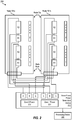
- FIG. 2 depicts a circuit diagram of a circuit 200 for deicing a propeller according to one or more embodiments described herein.
- the circuit 200 is associated with a propeller having two blades 204a, 204b (collectively the "blades 204").
- the blades 204 have a blade tip 210 and a blade root 211.
- the blade root is the portion of the blades 204 closest to the center point of the propeller (e.g., the center point 102 of FIG. 1 ).
- the blades 204 include heating elements for deicing the respective blades. Deicing is performed by providing a current to the heating elements to cause the heating elements to generate heat.
- a three-phase power generation device 220 generates a current across each of its phases: Phase A, Phase B, Phase C (labeled “A,” “B,” and “C” respectively in FIG. 2 ) for each of two heating (deicing) zones 1 and 2.
- a processing device 240 controls the heating of the propeller by enabling and disabling heating of the heating elements. For example, the processing device 240 can selectively activate and deactivate the heating elements in the zones, such as for particular periods of time.
- the processing device 240 can be any suitable processing device, processing circuit, etc., such as a field-programmable gate array, application-specific integrated circuit, central processing unit, special-purpose processor, microprocessor, digital signal processor, and the like, including combinations thereof.
- the functionality described herein can be a combination of hardware and programming.
- the programming can be processor executable instructions stored on a tangible memory (not shown), and the hardware can include the processing device 240 for executing those instructions.
- a system memory can store program instructions that when executed by the processing device 240 implement the logic described herein.
- each of the blades 204 includes two heating (or deicing) zones: zone 1 and zone 2.
- blade 204a includes zone 1 and zone 2; similarly, blade 204b includes zone 1 and zone 2.
- Each of the zones 1 and 2 of each of the blades 204 includes a heating element having two resistors R1, R2 configured and arranged as shown.
- the resistor R2 has a resistive value that is twice the resistive value of the resistor R1. For example, if the resistive value of R1 is 10 ⁇ , the resistive value of R2 is 20 ⁇ . This relationship between the resistive values of R1, R2 in the circuit 200 ensures that the load across each phase of the three-phase power generation device 220 is balanced (i.e., substantially the same).
- the three-phase power generation device 220 supplies a current across Phase A, Phase B, and Phase C for a first time period (e.g., 10 seconds) to zone 1.
- the current flows through the resistors R1, R2 in zone 1 of the blades 204. This is shown as zone 1 power 221.
- the three-phase power generation device 220 supplies a current across Phase A, Phase B, and Phase C for a second time period (e.g., 10 seconds) to zone 2.
- the current flows through the resistors R1, R2 in zone 2 of the blades 204. This is shown as zone 2 power 222. In this way, the power load across the phases of the three-phase power generation device 220 is balanced and the deicing of the blades 204 is also weight balanced.
- each deicer uses six (6) electrical leads that are then interconnected or connected to the appropriate phase of electrical power via additional electrical wiring after installation on the propeller as shown in FIG. 2 .
- the load applied between Phase A and Phase B is R2 in zone 1 of blade 1.
- the load between Phase B and Phase C is R1 of Zone 1 of blade 104a plus R1 of zone 1 of blade 104b.
- the load between Phase C and Phase A is R2 in zone 1 of blade 104b. Since by design R2 is equal to R1+R1, the load on each phase pair (i.e., phase pairs AB, BC, and CA) is the same (i.e. R1+R1).
- FIGS. 3A and 3B depict a circuit diagram of a circuit 300 for deicing a propeller according to one or more embodiments described herein.
- the circuit 300 is associated with a propeller having seven blades 104a-104g (collectively the "blades 204") as in FIG. 1 except that the interconnecting wiring for zone 2 is not shown for simplicity.
- the blades 104 include heating elements for deicing the respective blades. Deicing is performed by providing a current to the heating elements to cause the heating elements to generate heat.
- a three-phase power generation device 320 generates a current across each of its phases: Phase A, Phase B, Phase C (labeled “A,” “B,” and “C” respectively in FIG. 2 ) for each of two heating (deicing) zones 1 and 2.
- each of the blades 104 includes two heating (or deicing) zones: zone 1 and zone 2.
- blade 104a includes zone 1 and zone 2; similarly, blades 104b-104g each includes zone 1 and zone 2.
- Each of the zones 1 and 2 of each of the blades 104 includes a heating element having two resistors R1, R2 configured and arranged as shown.
- the resistor R2 has a resistive value that is twice the resistive value of the resistor R1. For example, if the resistive value of R1 is 10 ⁇ , the resistive value of R2 is 20 ⁇ . This relationship between the resistive values of R1, R2 in the circuit 300 ensures that the load across each phase of the three-phase power generation device 320 is balanced (i.e., substantially the same).
- the three-phase power generation device 320 supplies a current across Phase A, Phase B, and Phase C for a first time period (e.g., 10 seconds) to zone 1.
- the current flows through the resistors R1, R2 in zone 1 of the blades 104. This is shown as zone 1 power 321.
- the three-phase power generation device 220 supplies a current across Phase A, Phase B, and Phase C for a second time period (e.g., 10 seconds) to zone 2.
- the current flows through the resistors R1, R2 in zone 2 of the blades 104. This is shown as zone 2 power 322.
- zone 2 power 322 In this way, the power load across the phases of the three-phase power generation device 320 is balanced and the deicing of the blades 104 is also weight balanced.
- each deicer uses six (6) electrical leads that are then interconnected or connected to the appropriate phase of electrical power via additional electrical wiring after installation on the propeller as shown in FIGS. 3A and 3B for zone 1 (zone 2 is similarly interconnected but such connections are not shown for clarity).
- zone 1 load applied between Phase A and Phase B is R1 of blade 104a + R2 of blade 104a + R1 of blade 104b + R2 of blade 104b + R1 of blade 104c.
- the zone 1 load between Phase B and Phase C is R2 of blade 104c + R1 of blade 104d + R2 of blade 104d + R2 of blade 104e.
- FIG. 4 depicts a flow diagram of a method 400 for deicing a propeller, such as the propeller 100 of FIG. 1 , according to one or more embodiments described herein.
- the example of FIG. 4 is described with respect FIGS. 1 , 3A , and 3B but is not intended to be so limited.
- the method 400 includes performing a first heating, by a first plurality of heating elements (e.g., the heating elements 106) for a first period of time, of a first portion of each of a plurality of blades (e.g., the blades 104) of the propeller.
- the first portion of each of the plurality of blades of the propeller defines a first deicing zone (e.g., the first deicing zone 107).
- the first deicing zone is formed radially about a center point (e.g., the center point 102) of the propeller.
- the method 400 includes subsequent to expiration of the first period of time, performing a second heating, by a second plurality of heating elements (e.g., the heating elements 108) for a second period of time, of a second portion of each of the plurality of blades (e.g., the blades 104) of the propeller.
- the second portion of each of the plurality of blades of the propeller defines a second deicing zone (e.g., the second deicing zone 109).
- the second deicing zone is formed radially about the center point of the propeller.
- the second deicing zone differs from the first deicing zone (see, e.g., FIG. 1 ).
- a current is supplied to the respective first plurality of heating elements (e.g., the heating elements 106) and the second plurality of heating elements (e.g., the heating elements 108) from each of three phases (e.g., Phase A, Phase B, Phase C) of a three-phase power generation device (e.g., the three-phase power generation device 320) associated with the aircraft.
- a load on each of the three phases is balanced.
- one or more of the first plurality of heating elements and/or one or more of the second plurality of heating elements can include a resistive circuit.
- each of the blades 104 includes resistors R1, R2 (the first resistive circuit) in the first deicing zone and similarly includes resistors R1, R2 (the second resistive circuit) in the second deicing zone.
- the resistors R1, R2 of each blade 104 within the respective first or second deicing zone form a resistive circuit.
- the resistive value of the resistor R2 is approximately twice the value of the resistor R1.
- each of the three phases e.g., Phase A, Phase B, Phase C
- each of the three phases supplies current to the second heating elements during the second heating.
- heating the second portion of each of the plurality of blades of the propeller occurs within a threshold time (e.g., less than 1 second, 3 seconds, 5 seconds, 10 seconds, etc.) subsequent to the expiration of the first period of time.
- a threshold time e.g., less than 1 second, 3 seconds, 5 seconds, 10 seconds, etc.
- the method 400 subsequent to expiration of the first period of time, includes waiting a third period of time before performing the second heating. Then, according to one or more embodiments described herein, subsequent to expiration of third period of time, the method 400 includes performing a third heating, by the first plurality of heating elements for the first period of time, the first portion of each of the plurality of blades of the propeller; and subsequent to expiration of the first period of time, performing a fourth heating, by the second plurality of heating elements for the second period of time, the second portion of each of the plurality of blades of the propeller.
- the method 400 subsequent to the expiration of second period of time, includes performing a third heating, by the first plurality of heating elements for the first period of time, the first portion of each of the plurality of blades of the propeller.
- FIG. 4 represents an illustration, and that other processes may be added or existing processes may be removed, modified, or rearranged without departing from the scope of the present disclosure.
- the technical effects and benefits include improving power load balancing in a deicing system powered by a three-phase power generation device. Particularly, the power load across the phases of the three-phase power generation device is balanced, regardless of how many blades or their configuration. Further, the deicing of the blades is also weight balanced, regardless of how many blades or their configuration.
Landscapes
- Engineering & Computer Science (AREA)
- Aviation & Aerospace Engineering (AREA)
- Physics & Mathematics (AREA)
- Fluid Mechanics (AREA)
- Life Sciences & Earth Sciences (AREA)
- Sustainable Development (AREA)
- Sustainable Energy (AREA)
- Chemical & Material Sciences (AREA)
- Combustion & Propulsion (AREA)
- Mechanical Engineering (AREA)
- General Engineering & Computer Science (AREA)
- Surface Heating Bodies (AREA)
- Control Of Resistance Heating (AREA)
- Air-Conditioning For Vehicles (AREA)
Abstract
Description
- Embodiments described herein generally relate to deicing techniques, and more specifically to a multi-element propeller blade deicer scheme for balanced three-phase electrical loads.
- Deicing systems on aircraft reduce and/or prevent the accumulation of ice on aircraft surfaces such as propellors, wings, rotor blades, control surfaces, and other components. Different types of deicing systems include pneumatic deicing boots, electro-thermal systems, bleed air systems, electro-mechanical systems, among others. Electro-thermal systems use resistive circuits that are disposed within a particular component and that generate heat when a current passes through the resistive circuits. The heat causes the reduction and/or prevention of the accumulation of ice.
- According to an embodiment, a method for deicing an aircraft propeller having a plurality of blades of an aircraft is provided. The method includes performing a first heating, by a first plurality of heating elements connected to a first portion of each of the plurality of blades, for a first period of time, the first portion of each of the plurality of blades of the propeller defining a first deicing zone, the first deicing zone being formed radially about a center point of the propeller. The method further includes, subsequent to expiration of the first period of time, performing a second heating, by a second plurality of heating elements connected to a second portion of each of the plurality of blades, for a second period of time, the second portion of each of the plurality of blades of the propeller defining a second deicing zone, the second deicing zone being formed radially about the center point of the propeller, the second deicing zone differing from the first deicing zone. While performing the first heating and while performing the second heating, a current is supplied to the respective first plurality of heating elements and the second plurality of heating elements from each of three phases of a three-phase power generation device associated with the aircraft, a load on each of the three phases being balanced.
- In addition to one or more of the features described herein, or as an alternative, further embodiments include that one or more of the first plurality of heating elements comprises a first resistive circuit.
- In addition to one or more of the features described herein, or as an alternative, further embodiments include that performing the first heating comprises receiving the current from each of the three phases of the three-phase power generation device associated with the aircraft during the first period of time.
- In addition to one or more of the features described herein, or as an alternative, further embodiments include that the first resistive circuit comprises a first resistor and a second resistor, the second resistor having twice the resistance of the first resistor.
- In addition to one or more of the features described herein, or as an alternative, further embodiments include that one or more of the second plurality of heating elements comprises a second resistive circuit.
- In addition to one or more of the features described herein, or as an alternative, further embodiments include that performing the second heating comprises receiving the current from each of the three phases of the three-phase power generation device associated with the aircraft during the second period of time.
- In addition to one or more of the features described herein, or as an alternative, further embodiments include that the second resistive circuit comprises a third resistor and a fourth resistor, the fourth resistor having twice the resistance of the third resistor.
- In addition to one or more of the features described herein, or as an alternative, further embodiments include that heating the second portion of each of the plurality of blades of the propeller occurs within a threshold time subsequent to expiration of the first period of time.
- In addition to one or more of the features described herein, or as an alternative, further embodiments include, subsequent to expiration of the first period of time, waiting a third period of time.
- In addition to one or more of the features described herein, or as an alternative, further embodiments include, subsequent to expiration of the third period of time, performing a third heating, by the first plurality of heating elements for the first period of time, the first portion of each of the plurality of blades of the propeller; and subsequent to expiration of the first period of time, performing a fourth heating, by the second plurality of heating elements for the second period of time, the second portion of each of the plurality of blades of the propeller.
- In addition to one or more of the features described herein, or as an alternative, further embodiments include that subsequent to expiration of the second period of time, performing a third heating, by the first plurality of heating elements for the first period of time, the first portion of each of the plurality of blades of the propeller.
- According to an embodiment, an aircraft is provided. The aircraft includes a propeller comprising a first plurality of heating elements disposed in a plurality of blades of the propeller and a second plurality of heating elements disposed in the plurality of blades of the propeller, wherein each of the plurality of first heating elements is disposed between a center point of the propeller and the respective each of the second heating elements. The aircraft further includes a three-phase power generation device selectively providing a current to the first plurality of heating elements and the second plurality of heating elements. The aircraft further includes a processing device for executing computer readable instructions stored in a memory, the computer readable instructions controlling the processing device to perform operations. The operations include causing heating, by the first plurality of heating elements connected to a first portion of each of the plurality of blades, for a first period of time, the first portion of each of the plurality of blades of the propeller defining a first deicing zone, the first deicing zone being formed radially about a center point of the propeller. The operations further include subsequent to expiration of the first period of time, causing heating, by the second plurality of heating elements connected to a second portion of each of the plurality of blades, for a second period of time, the second portion of each of the plurality of blades of the propeller defining a second deicing zone, the second deicing zone being formed radially about the center point of the propeller, the second deicing zone differing from the first deicing zone. While performing the first heating and while performing the second heating, the current is supplied to the respective first plurality of heating elements and the second plurality of heating elements from each of three phases of the three-phase power generation device, a load on each of the three phases being balanced.
- In addition to one or more of the features described herein, or as an alternative, further embodiments include that one or more of the first plurality of heating elements comprises a first resistive circuit.
- In addition to one or more of the features described herein, or as an alternative, further embodiments include that performing the first heating comprises receiving the current from each of the three phases of the three-phase power generation device associated with the aircraft during the first period of time.
- In addition to one or more of the features described herein, or as an alternative, further embodiments include that the first resistive circuit comprises a first resistor and a second resistor, the second resistor having twice the resistance of the first resistor.
- In addition to one or more of the features described herein, or as an alternative, further embodiments include that one or more of the second plurality of heating elements comprises a second resistive circuit.
- In addition to one or more of the features described herein, or as an alternative, further embodiments include that performing the second heating comprises receiving the current from each of the three phases of the three-phase power generation device associated with the aircraft during the second period of time.
- In addition to one or more of the features described herein, or as an alternative, further embodiments include that the second resistive circuit comprises a third resistor and a fourth resistor, the fourth resistor having twice the resistance of the third resistor.
- In addition to one or more of the features described herein, or as an alternative, further embodiments include that heating the second portion of each of the plurality of blades of the propeller occurs within a threshold time subsequent to expiration of the first period of time.
- According to an embodiment, a deicing system for deicing a plurality of blades of a propeller is provided. The deicing system includes a first plurality of heating elements and a second plurality of heating elements. The deicing system further includes a processing device for executing computer readable instructions stored in a memory, the computer readable instructions controlling the processing device to perform operations. The operations include causing heating, by the first plurality of heating elements connected to a first portion of each of the plurality of blades, for a first period of time, the first portion of each of the plurality of blades of the propeller defining a first deicing zone, the first deicing zone being formed radially about a center point of the propeller. The operations further include, subsequent to expiration of the first period of time, causing heating, by the second plurality of heating elements connected to a second portion of each of the plurality of blades, for a second period of time, the second portion of each of the plurality of blades of the propeller defining a second deicing zone, the second deicing zone being formed radially about the center point of the propeller, the second deicing zone differing from the first deicing zone. While performing the first heating and while performing the second heating, the current is supplied to the respective first plurality of heating elements and the second plurality of heating elements from each of three phases of the three-phase power generation device, a load on each of the three phases being balanced.
- The subject matter which is regarded as the present disclosure is particularly pointed out and distinctly claimed in the claims at the conclusion of the specification. The foregoing and other features, and advantages of the present disclosure are apparent from the following detailed description taken in conjunction with the accompanying drawings in which:
-
FIG. 1 depicts a cross-sectional view of a propeller having a plurality of deicing (or heating) zones defined radially about a center point of the propeller according to one or more embodiments described herein; -
FIG. 2 depicts a circuit diagram of a circuit for deicing a propeller according to one or more embodiments described herein; -
FIGS. 3A and3B depict a circuit diagram of a circuit for deicing a propeller according to one or more embodiments described herein; and -
FIG. 4 depicts a flow diagram of a method for deicing a propeller according to one or more embodiments described herein. - Aircraft can utilize different engine and propeller configurations. For example, an aircraft can utilize a singe engine or multiple engines (e.g., two engines, four engines, etc.). Each engine can have a propeller having a number of blades that can vary across aircraft types. Some aircraft can utilize a two-blade propeller configuration, while other aircraft can utilize multi-blade propeller configurations (e.g., three blades, four blades, five blades, six blades, seven blades, eight blades, etc.).
- With some propeller configurations (i.e., different blade counts), it may be difficult to provide a balanced power load to be placed on a power source (e.g., alternator or generator) due to a propeller deicing system. While different propeller deicing and anti-icing zones have been utilized to minimize the peak power demand while approximately balancing the load on the three-phases of an alternator/generator output of the aircraft, a balanced power load is not always achieved. Accordingly, it is desirable to provide a balanced power load from the propeller deicing system to the aircraft power generation system while minimizing peak power demand for the overall propeller ice protection function of the propeller deicing system. As the propeller ice protection system is not always active, a balanced load on the three-phase power generating device is desirable with the propeller ice protection system both active and inactive.
- Further, providing for weight-balanced deicing of the propeller blades is desirable. For example, a six-blade propeller configuration can be divided into three zones of two blades each. In such an arrangement, two opposite blades are paired together in a zone. This enables symmetrical weight-balanced deicing so that when ice is released from the blades receiving heating power from the propeller deicing system, the propeller assembly remains roughly in balance and avoids the generation of excessive vibration. However, providing for weight-balanced deicing may be especially difficult for certain blade configurations, such as a seven-blade configuration, that are not easily divisible.
- Some conventional propeller deicing systems cycle between powering heaters ON and OFF. Typical heater power ON and power OFF durations establish the heat needed to weaken the bond between any ice that builds up on the propeller blade surface (during the OFF time) while not supplying too much power during the ON time that liquid water can run back to an unheated area on the propeller blade and cause loss of aerodynamic performance.
- In periods of severe icing, a traditional duty cycle for the heater is 20 seconds ON followed by 60 seconds OFF, although other durations for ON and OFF times are possible. This allows for four deicing zones to be established and power applied to each zone in sequence such that the peak power requested from the power generation system is only 25% of the power that would be required to power all zones simultaneously. One technique of establishing four deicing zones with a two-propeller aircraft is to define two zones on each propeller.
- When defining two zones per propeller on a four, six, or eight bladed propeller, this can be accomplished by defining the even blades as one zone and the odd blades as a second zone. In the event of an odd number of blades on the propeller, this split by entire blades approach is not possible. In the event of a two-bladed propeller, symmetric deicing is not possible when deicing whole blades, unless the peak power request is allowed to increase to 50% rather than the optimum 25% figure, discussed earlier.
- The present techniques address these and other shortcomings of the prior art by providing a propeller deicing system having a multi-element propeller blade deicer arrangement for balanced three-phase electrical loads. The disclosed techniques may provide the ability to draw electrical power from a three-phase alternating current (AC) electrical generation system on an aircraft in a balanced manner while minimizing the peak power required for propeller ice protection functions provided by a propeller deicing system.
- According to one or more embodiments described herein, the propeller deicing system has multiple heating elements to allow the creation of radial deicing zones on the blades of a propeller. The radial deicing zones are based on radial location of the heating elements rather than the blade location. Deicing zones form concentric circles about the center of the propeller according to some examples. This approach implements multiple power feeds to each deicing zone such that the total electrical load applied to each of the three phases of a three-phase AC power generation system is balanced. This approach reduces generation weight and improves generation reliability. Of note is that beyond a certain radial station on the propeller blade, deicers are no longer needed as the centrifugal forces that exist during propeller rotation are capable of removing any ice build-up without additional heating of the ice/blade interface.
-
FIG. 1 depicts a cross-sectional view of apropeller 100 having a plurality of deicing (or heating) zones defined radially about acenter point 102 of thepropeller 100 according to one or more embodiments described herein. In this example, thepropeller 100 includes sevenblades - In this example, the blades 104 each include heating elements that define deicing zones. For example, the
blade 104a includesheating elements blades heating elements heating elements FIGS. 2 ,3A , and3B . The heating elements 106 form afirst deicing zone 107 and the heating elements 108 form asecond deicing zone 109. Thefirst deicing zone 107 is formed radially about thecenter point 102 of thepropeller 100 as shown using a first style of crosshatching inFIG. 1 . Thesecond deicing zone 109 is also formed radially about thecenter point 102 of thepropeller 100 as shown using a second style of crosshatching inFIG. 1 . In this way, thefirst deicing zone 107 and thesecond deicing zone 109 form adjacent, non-overlapping concentric rings about thecenter point 102 configured and arranged as shown. - The heating elements 106, 108 can include resistive circuits that generate heat to facilitate deicing.
FIGS. 2 ,3A , and3B depict examples of such resistive circuits. For example,FIG. 2 depicts a circuit diagram of acircuit 200 for deicing a propeller according to one or more embodiments described herein. In this example, thecircuit 200 is associated with a propeller having twoblades blade tip 210 and ablade root 211. The blade root is the portion of the blades 204 closest to the center point of the propeller (e.g., thecenter point 102 ofFIG. 1 ). - The blades 204 include heating elements for deicing the respective blades. Deicing is performed by providing a current to the heating elements to cause the heating elements to generate heat. In particular, a three-phase
power generation device 220 generates a current across each of its phases: Phase A, Phase B, Phase C (labeled "A," "B," and "C" respectively inFIG. 2 ) for each of two heating (deicing)zones processing device 240 controls the heating of the propeller by enabling and disabling heating of the heating elements. For example, theprocessing device 240 can selectively activate and deactivate the heating elements in the zones, such as for particular periods of time. Theprocessing device 240 can be any suitable processing device, processing circuit, etc., such as a field-programmable gate array, application-specific integrated circuit, central processing unit, special-purpose processor, microprocessor, digital signal processor, and the like, including combinations thereof. According to aspects of the present disclosure, the functionality described herein can be a combination of hardware and programming. The programming can be processor executable instructions stored on a tangible memory (not shown), and the hardware can include theprocessing device 240 for executing those instructions. Thus a system memory can store program instructions that when executed by theprocessing device 240 implement the logic described herein. - In particular, as shown, each of the blades 204 includes two heating (or deicing) zones:
zone 1 andzone 2. For example,blade 204a includeszone 1 andzone 2; similarly,blade 204b includeszone 1 andzone 2. Each of thezones circuit 200 ensures that the load across each phase of the three-phasepower generation device 220 is balanced (i.e., substantially the same). - As an example, the three-phase
power generation device 220 supplies a current across Phase A, Phase B, and Phase C for a first time period (e.g., 10 seconds) tozone 1. The current flows through the resistors R1, R2 inzone 1 of the blades 204. This is shown aszone 1power 221. After the first time period expires, the three-phasepower generation device 220 supplies a current across Phase A, Phase B, and Phase C for a second time period (e.g., 10 seconds) tozone 2. The current flows through the resistors R1, R2 inzone 2 of the blades 204. This is shown aszone 2power 222. In this way, the power load across the phases of the three-phasepower generation device 220 is balanced and the deicing of the blades 204 is also weight balanced. - To allow for a common heating element (i.e., "deicer") to be installed on each blade 204, each deicer uses six (6) electrical leads that are then interconnected or connected to the appropriate phase of electrical power via additional electrical wiring after installation on the propeller as shown in
FIG. 2 . In this example of a 2-bladed propeller, the load applied between Phase A and Phase B is R2 inzone 1 ofblade 1. The load between Phase B and Phase C is R1 ofZone 1 ofblade 104a plus R1 ofzone 1 ofblade 104b. The load between Phase C and Phase A is R2 inzone 1 ofblade 104b. Since by design R2 is equal to R1+R1, the load on each phase pair (i.e., phase pairs AB, BC, and CA) is the same (i.e. R1+R1). - As another example resistive circuit,
FIGS. 3A and3B depict a circuit diagram of acircuit 300 for deicing a propeller according to one or more embodiments described herein. In this example, thecircuit 300 is associated with a propeller having sevenblades 104a-104g (collectively the "blades 204") as inFIG. 1 except that the interconnecting wiring forzone 2 is not shown for simplicity. - The blades 104 include heating elements for deicing the respective blades. Deicing is performed by providing a current to the heating elements to cause the heating elements to generate heat. In particular, a three-phase
power generation device 320 generates a current across each of its phases: Phase A, Phase B, Phase C (labeled "A," "B," and "C" respectively inFIG. 2 ) for each of two heating (deicing)zones - In particular, as shown, each of the blades 104 includes two heating (or deicing) zones:
zone 1 andzone 2. For example,blade 104a includeszone 1 andzone 2; similarly,blades 104b-104g each includeszone 1 andzone 2. Each of thezones circuit 300 ensures that the load across each phase of the three-phasepower generation device 320 is balanced (i.e., substantially the same). - As an example, the three-phase
power generation device 320 supplies a current across Phase A, Phase B, and Phase C for a first time period (e.g., 10 seconds) tozone 1. The current flows through the resistors R1, R2 inzone 1 of the blades 104. This is shown aszone 1power 321. After the first time period expires, the three-phasepower generation device 220 supplies a current across Phase A, Phase B, and Phase C for a second time period (e.g., 10 seconds) tozone 2. The current flows through the resistors R1, R2 inzone 2 of the blades 104. This is shown aszone 2power 322. In this way, the power load across the phases of the three-phasepower generation device 320 is balanced and the deicing of the blades 104 is also weight balanced. - To allow for a common heating element (i.e., "deicer") to be installed on each blade 104, each deicer uses six (6) electrical leads that are then interconnected or connected to the appropriate phase of electrical power via additional electrical wiring after installation on the propeller as shown in
FIGS. 3A and3B for zone 1 (zone 2 is similarly interconnected but such connections are not shown for clarity). In this example of a 7-bladed propeller, thezone 1 load applied between Phase A and Phase B is R1 ofblade 104a + R2 ofblade 104a + R1 ofblade 104b + R2 ofblade 104b + R1 ofblade 104c. Thezone 1 load between Phase B and Phase C is R2 ofblade 104c + R1 ofblade 104d + R2 ofblade 104d + R2 ofblade 104e. Thezone 1 load between Phase C and Phase A is, therefore, R1 ofblade 104e + R1 ofblade 104f + R2 ofblade 104f + R1 ofblade 104g + R2 of blade 104. Since by design R2 = R1+R1, the load on each phase pair (AB, BC, and CA) is the same (i.e. 7xR1). -
FIG. 4 depicts a flow diagram of amethod 400 for deicing a propeller, such as thepropeller 100 ofFIG. 1 , according to one or more embodiments described herein. The example ofFIG. 4 is described with respectFIGS. 1 ,3A , and3B but is not intended to be so limited. - At
block 402, themethod 400 includes performing a first heating, by a first plurality of heating elements (e.g., the heating elements 106) for a first period of time, of a first portion of each of a plurality of blades (e.g., the blades 104) of the propeller. The first portion of each of the plurality of blades of the propeller defines a first deicing zone (e.g., the first deicing zone 107). The first deicing zone is formed radially about a center point (e.g., the center point 102) of the propeller. - At
block 404, themethod 400 includes subsequent to expiration of the first period of time, performing a second heating, by a second plurality of heating elements (e.g., the heating elements 108) for a second period of time, of a second portion of each of the plurality of blades (e.g., the blades 104) of the propeller. The second portion of each of the plurality of blades of the propeller defines a second deicing zone (e.g., the second deicing zone 109). The second deicing zone is formed radially about the center point of the propeller. The second deicing zone differs from the first deicing zone (see, e.g.,FIG. 1 ). - While performing the first heating (block 402) and while performing the second heating (block 404), a current is supplied to the respective first plurality of heating elements (e.g., the heating elements 106) and the second plurality of heating elements (e.g., the heating elements 108) from each of three phases (e.g., Phase A, Phase B, Phase C) of a three-phase power generation device (e.g., the three-phase power generation device 320) associated with the aircraft. A load on each of the three phases is balanced.
- In some examples, as shown in
FIG. 3A and3B , one or more of the first plurality of heating elements and/or one or more of the second plurality of heating elements can include a resistive circuit. For example, as shown inFIG. 3A and3B , each of the blades 104 includes resistors R1, R2 (the first resistive circuit) in the first deicing zone and similarly includes resistors R1, R2 (the second resistive circuit) in the second deicing zone. Together, the resistors R1, R2 of each blade 104 within the respective first or second deicing zone form a resistive circuit. The resistive value of the resistor R2 is approximately twice the value of the resistor R1. According to one or more embodiments described herein, each of the three phases (e.g., Phase A, Phase B, Phase C) supplies current to the first heating elements during the first heating; similarly, each of the three phases supplies current to the second heating elements during the second heating. - Additional processes also may be included. For example, according to one or more embodiments described herein, heating the second portion of each of the plurality of blades of the propeller occurs within a threshold time (e.g., less than 1 second, 3 seconds, 5 seconds, 10 seconds, etc.) subsequent to the expiration of the first period of time.
- According to one or more embodiments described herein, subsequent to expiration of the first period of time, the
method 400 includes waiting a third period of time before performing the second heating. Then, according to one or more embodiments described herein, subsequent to expiration of third period of time, themethod 400 includes performing a third heating, by the first plurality of heating elements for the first period of time, the first portion of each of the plurality of blades of the propeller; and subsequent to expiration of the first period of time, performing a fourth heating, by the second plurality of heating elements for the second period of time, the second portion of each of the plurality of blades of the propeller. - According to one or more embodiments described herein, subsequent to the expiration of second period of time, the
method 400 includes performing a third heating, by the first plurality of heating elements for the first period of time, the first portion of each of the plurality of blades of the propeller. - It should be understood that the process depicted in
FIG. 4 represents an illustration, and that other processes may be added or existing processes may be removed, modified, or rearranged without departing from the scope of the present disclosure. - The technical effects and benefits include improving power load balancing in a deicing system powered by a three-phase power generation device. Particularly, the power load across the phases of the three-phase power generation device is balanced, regardless of how many blades or their configuration. Further, the deicing of the blades is also weight balanced, regardless of how many blades or their configuration.
- While the present disclosure has been described in detail in connection with only a limited number of embodiments, it should be readily understood that the present disclosure is not limited to such disclosed embodiments. Rather, the present disclosure can be modified to incorporate any number of variations, alterations, substitutions or equivalent arrangements not heretofore described, but which are commensurate with the scope of the invention as defined by the claims. Additionally, while various embodiments of the present disclosure have been described, it is to be understood that aspects of the present disclosure may include only some of the described embodiments. Accordingly, the present disclosure is not to be seen as limited by the foregoing description, but is only limited by the scope of the appended claims.
Claims (15)
- A method for deicing an aircraft propeller having a plurality of blades of an aircraft, the method comprising:performing a first heating, by a first plurality of heating elements (106) connected to a first portion of each of the plurality of blades (104), for a first period of time, the first portion of each of the plurality of blades of the propeller defining a first deicing zone (107), the first deicing zone being formed radially about a center point (102) of the propeller (100); andsubsequent to expiration of the first period of time, performing a second heating, by a second plurality of heating elements (108) connected to a second portion of each of the plurality of blades, for a second period of time, the second portion of each of the plurality of blades of the propeller defining a second deicing zone (109), the second deicing zone being formed radially about the center point (102) of the propeller, the second deicing zone differing from the first deicing zone,wherein, while performing the first heating and while performing the second heating, a current is supplied to the respective first plurality of heating elements and the second plurality of heating elements from each of three phases of a three-phase power generation device associated with the aircraft, a load on each of the three phases being balanced.
- The method of claim 1, wherein one or more of the first plurality of heating elements comprises a first resistive circuit, and optionally wherein performing the first heating comprises receiving the current from each of the three phases of the three-phase power generation device associated with the aircraft during the first period of time.
- The method of claim 2, wherein the first resistive circuit comprises a first resistor and a second resistor, the second resistor having twice the resistance of the first resistor.
- The method of any preceding claim, wherein one or more of the second plurality of heating elements comprises a second resistive circuit, and optionally wherein performing the second heating comprises receiving the current from each of the three phases of the three-phase power generation device associated with the aircraft during the second period of time.
- The method of claim 4, wherein the second resistive circuit comprises a third resistor and a fourth resistor, the fourth resistor having twice the resistance of the third resistor.
- The method of any preceding claim, wherein heating the second portion of each of the plurality of blades of the propeller occurs within a threshold time subsequent to expiration of the first period of time.
- The method of any preceding claim, further comprising:
subsequent to expiration of the first period of time, waiting a third period of time, and optionally:subsequent to expiration of the third period of time, performing a third heating, by the first plurality of heating elements for the first period of time, the first portion of each of the plurality of blades of the propeller; andsubsequent to expiration of the first period of time, performing a fourth heating, by the second plurality of heating elements for the second period of time, the second portion of each of the plurality of blades of the propeller. - The method of any of claims 1 to 6, further comprising:
subsequent to expiration of the second period of time, performing a third heating, by the first plurality of heating elements for the first period of time, the first portion of each of the plurality of blades of the propeller. - An aircraft comprising:a propeller (100) comprising a first plurality of heating elements (106) disposed in a plurality of blades (104) of the propeller and a second plurality of heating elements (108) disposed in the plurality of blades of the propeller, wherein each of the plurality of first heating elements is disposed between a center point (102) of the propeller and the respective each of the second heating elements;a three-phase power generation device (220) selectively providing a current to the first plurality of heating elements and the second plurality of heating elements; anda processing device (240) for executing computer readable instructions stored in a memory, the computer readable instructions controlling the processing device to perform operations comprising:causing heating, by the first plurality of heating elements connected to a first portion of each of the plurality of blades, for a first period of time, the first portion of each of the plurality of blades of the propeller defining a first deicing zone, the first deicing zone being formed radially about a center point of the propeller; andsubsequent to expiration of the first period of time, causing heating, by the second plurality of heating elements connected to a second portion of each of the plurality of blades, for a second period of time, the second portion of each of the plurality of blades of the propeller defining a second deicing zone, the second deicing zone being formed radially about the center point of the propeller, the second deicing zone differing from the first deicing zone,wherein, while performing the first heating and while performing the second heating, the current is supplied to the respective first plurality of heating elements and the second plurality of heating elements from each of three phases of the three-phase power generation device, a load on each of the three phases being balanced.
- The aircraft of claim 9, wherein one or more of the first plurality of heating elements comprises a first resistive circuit, and optionally wherein performing the first heating comprises receiving the current from each of the three phases of the three-phase power generation device associated with the aircraft during the first period of time.
- The aircraft of claim 10, wherein the first resistive circuit comprises a first resistor and a second resistor, the second resistor having twice the resistance of the first resistor.
- The aircraft of claim 9, 10 or 11, wherein one or more of the second plurality of heating elements comprises a second resistive circuit, and optionally
wherein performing the second heating comprises receiving the current from each of the three phases of the three-phase power generation device associated with the aircraft during the second period of time. - The aircraft of claim 12, wherein the second resistive circuit comprises a third resistor and a fourth resistor, the fourth resistor having twice the resistance of the third resistor.
- The aircraft of any of claims 9 to 13, wherein heating the second portion of each of the plurality of blades of the propeller occurs within a threshold time subsequent to expiration of the first period of time.
- A deicing system for deicing a plurality of blades of a propeller , the deicing system comprising:a first plurality of heating elements (106);a second plurality of heating elements (108); anda processing device (240) for executing computer readable instructions stored in a memory, the computer readable instructions controlling the processing device to perform operations comprising:causing heating, by the first plurality of heating elements connected to a first portion of each of the plurality of blades, for a first period of time, the first portion of each of the plurality of blades of the propeller defining a first deicing zone, the first deicing zone being formed radially about a center point of the propeller; andsubsequent to expiration of the first period of time, causing heating, by the second plurality of heating elements connected to a second portion of each of the plurality of blades, for a second period of time, the second portion of each of the plurality of blades of the propeller defining a second deicing zone, the second deicing zone being formed radially about the center point of the propeller, the second deicing zone differing from the first deicing zone,wherein, while performing the first heating and while performing the second heating, the current is supplied to the respective first plurality of heating elements and the second plurality of heating elements from each of three phases of the three-phase power generation device, a load on each of the three phases being balanced.
Applications Claiming Priority (1)
| Application Number | Priority Date | Filing Date | Title |
|---|---|---|---|
| US202063002793P | 2020-03-31 | 2020-03-31 |
Publications (1)
| Publication Number | Publication Date |
|---|---|
| EP3889046A1 true EP3889046A1 (en) | 2021-10-06 |
Family
ID=75339533
Family Applications (1)
| Application Number | Title | Priority Date | Filing Date |
|---|---|---|---|
| EP21166282.0A Pending EP3889046A1 (en) | 2020-03-31 | 2021-03-31 | Multi-element propeller blade deicer scheme for balanced three-phase electrical loads |
Country Status (4)
| Country | Link |
|---|---|
| US (1) | US12116138B2 (en) |
| EP (1) | EP3889046A1 (en) |
| CN (1) | CN113460311A (en) |
| CA (1) | CA3110197A1 (en) |
Families Citing this family (2)
| Publication number | Priority date | Publication date | Assignee | Title |
|---|---|---|---|---|
| US11999493B2 (en) * | 2021-03-31 | 2024-06-04 | Goodrich Corporation | Method and system for ice shed |
| CN119689109A (en) * | 2024-12-05 | 2025-03-25 | 武汉航空仪表有限责任公司 | A method and device for detecting fault of a helicopter main blade heating assembly |
Citations (4)
| Publication number | Priority date | Publication date | Assignee | Title |
|---|---|---|---|---|
| WO2006124026A1 (en) * | 2005-05-16 | 2006-11-23 | Bell Helicopter Textron Inc. | Ice management system for tiltrotor aircraft |
| GB2447374A (en) * | 2004-01-30 | 2008-09-10 | Ultra Electronics Ltd | Modular aircraft control system and method |
| GB2449651A (en) * | 2007-05-29 | 2008-12-03 | Ultra Electronics Ltd | Power control system to reduce imbalances |
| EP2520492A1 (en) * | 2011-05-03 | 2012-11-07 | Goodrich Corporation | Ice protection system |
Family Cites Families (14)
| Publication number | Priority date | Publication date | Assignee | Title |
|---|---|---|---|---|
| US6137082A (en) * | 1998-05-29 | 2000-10-24 | United Technologies Corporation | Multiple piece propeller deicing system brush block housings |
| US6069341A (en) * | 1998-05-29 | 2000-05-30 | United Technologies Corporation | Brush block housing for propeller deicing system |
| US6227492B1 (en) * | 1999-08-06 | 2001-05-08 | Bell Helicopter Textron Inc. | Redundant ice management system for aircraft |
| US6851929B2 (en) | 2002-03-19 | 2005-02-08 | Hamilton Sundstrand | System for powering and controlling a device associated with a rotating component on aircraft |
| US7604202B2 (en) | 2005-02-24 | 2009-10-20 | Bell Helicopter Textron Inc. | Ice management system for tiltrotor aircraft |
| US8466390B2 (en) | 2008-01-08 | 2013-06-18 | Rosemount Aerospace Inc. | Heater control architecture for an ice protection system |
| AT508327A1 (en) * | 2008-07-29 | 2010-12-15 | Villinger Markus | HEATING DEVICE FOR DEPARTING AIRCRAFT PARTS |
| US9656757B2 (en) | 2008-09-16 | 2017-05-23 | Hamilton Sundstrand Corporation | Propeller deicing system |
| GB201301789D0 (en) * | 2013-02-01 | 2013-03-20 | Rolls Royce Plc | A de-icing apparatus and a method of using the same |
| US9638044B2 (en) * | 2014-03-11 | 2017-05-02 | Hamilton Sundstrand Corporation | Resistive-inductive propeller blade de-icing system including contactless power supply |
| US9745070B2 (en) * | 2014-11-11 | 2017-08-29 | The Boeing Company | Systems for multiple zone heaters for rotor craft and methods of operation |
| CN107521702B (en) * | 2017-07-13 | 2020-04-21 | 中国航空工业集团公司西安飞机设计研究所 | An optimization method for aircraft electrothermal deicing system |
| US10710732B2 (en) * | 2017-09-15 | 2020-07-14 | Bell Helicopter Textron Inc. | Rotary aircraft ice protection system |
| GB2607884B (en) * | 2021-06-11 | 2023-11-15 | Ubiq Aerospace As | System and method for deicing of a carbon composite propeller |
-
2021
- 2021-02-23 CA CA3110197A patent/CA3110197A1/en active Pending
- 2021-03-05 CN CN202110246024.5A patent/CN113460311A/en active Pending
- 2021-03-31 US US17/219,096 patent/US12116138B2/en active Active
- 2021-03-31 EP EP21166282.0A patent/EP3889046A1/en active Pending
Patent Citations (4)
| Publication number | Priority date | Publication date | Assignee | Title |
|---|---|---|---|---|
| GB2447374A (en) * | 2004-01-30 | 2008-09-10 | Ultra Electronics Ltd | Modular aircraft control system and method |
| WO2006124026A1 (en) * | 2005-05-16 | 2006-11-23 | Bell Helicopter Textron Inc. | Ice management system for tiltrotor aircraft |
| GB2449651A (en) * | 2007-05-29 | 2008-12-03 | Ultra Electronics Ltd | Power control system to reduce imbalances |
| EP2520492A1 (en) * | 2011-05-03 | 2012-11-07 | Goodrich Corporation | Ice protection system |
Also Published As
| Publication number | Publication date |
|---|---|
| BR102021004532A2 (en) | 2021-10-13 |
| CN113460311A (en) | 2021-10-01 |
| CA3110197A1 (en) | 2021-09-30 |
| US20210300573A1 (en) | 2021-09-30 |
| US12116138B2 (en) | 2024-10-15 |
Similar Documents
| Publication | Publication Date | Title |
|---|---|---|
| AU2017410335B2 (en) | Electric drive train and method for feeding an electric drive train | |
| EP3670349B1 (en) | Motor driven propulsor of an aircraft | |
| US11932125B2 (en) | Rotor break effect by using electric distributed anti-torque generators and opposing electric motor thrust to slow a main rotor | |
| US12116138B2 (en) | Multi-element propeller blade deicer scheme for balanced three-phase electrical loads | |
| EP2762407B1 (en) | A de-icing apparatus and a method of using the same | |
| US7604202B2 (en) | Ice management system for tiltrotor aircraft | |
| RU2700151C9 (en) | Systems for combined zones heaters for aircraft with rotor and methods for operation thereof | |
| EP1882390B1 (en) | Ice management system for tiltrotor aircraft | |
| WO2022159969A1 (en) | Systems and methods for power distribution in electric aircraft | |
| US11396844B2 (en) | Fan blade, engine, and structure with anti-icing and de-icing functions | |
| EP2110314A2 (en) | De-icing system for engine inlet and method of preventing ice formation | |
| US11772807B2 (en) | Electric distributed anti-torque architecture | |
| US12166371B2 (en) | Battery charge difference calculation system | |
| US12567613B2 (en) | Aircraft thermal management system for an energy storage system | |
| JP2024020679A (en) | Vertical takeoff and landing aircraft power supply system | |
| BR102021004532B1 (en) | METHOD FOR DE-FROSTING AN AIRCRAFT PROPELLER, AIRCRAFT, AND DE-FROSTING SYSTEM FOR DE-FROSTING A MULTIPLE PROPELLER BLADES | |
| US9771164B2 (en) | Electric system architecture included in a more-electric engine (MEE) system | |
| CN118270241A (en) | Rotor blade deicing system and method | |
| EP2805885B1 (en) | On-blade deice heater mat | |
| EP4160905B1 (en) | Induction motor control via generator control unit | |
| CN221954572U (en) | Rotor blade deicing system | |
| US20240250527A1 (en) | Power supply for an aircraft | |
| US20260049573A1 (en) | Propeller of an aircraft turbine engine and method for de-icing same | |
| CN117738846A (en) | Device and method for controlling driver of pitch system |
Legal Events
| Date | Code | Title | Description |
|---|---|---|---|
| PUAI | Public reference made under article 153(3) epc to a published international application that has entered the european phase |
Free format text: ORIGINAL CODE: 0009012 |
|
| STAA | Information on the status of an ep patent application or granted ep patent |
Free format text: STATUS: THE APPLICATION HAS BEEN PUBLISHED |
|
| AK | Designated contracting states |
Kind code of ref document: A1 Designated state(s): AL AT BE BG CH CY CZ DE DK EE ES FI FR GB GR HR HU IE IS IT LI LT LU LV MC MK MT NL NO PL PT RO RS SE SI SK SM TR |
|
| STAA | Information on the status of an ep patent application or granted ep patent |
Free format text: STATUS: REQUEST FOR EXAMINATION WAS MADE |
|
| 17P | Request for examination filed |
Effective date: 20220405 |
|
| RBV | Designated contracting states (corrected) |
Designated state(s): AL AT BE BG CH CY CZ DE DK EE ES FI FR GB GR HR HU IE IS IT LI LT LU LV MC MK MT NL NO PL PT RO RS SE SI SK SM TR |
|
| STAA | Information on the status of an ep patent application or granted ep patent |
Free format text: STATUS: EXAMINATION IS IN PROGRESS |
|
| 17Q | First examination report despatched |
Effective date: 20221222 |
|
| GRAP | Despatch of communication of intention to grant a patent |
Free format text: ORIGINAL CODE: EPIDOSNIGR1 |
|
| STAA | Information on the status of an ep patent application or granted ep patent |
Free format text: STATUS: GRANT OF PATENT IS INTENDED |
|
| INTG | Intention to grant announced |
Effective date: 20260319 |