EP3888894A1 - Laminate wafers containing a soft deformable inner film - Google Patents
Laminate wafers containing a soft deformable inner film Download PDFInfo
- Publication number
- EP3888894A1 EP3888894A1 EP20167150.0A EP20167150A EP3888894A1 EP 3888894 A1 EP3888894 A1 EP 3888894A1 EP 20167150 A EP20167150 A EP 20167150A EP 3888894 A1 EP3888894 A1 EP 3888894A1
- Authority
- EP
- European Patent Office
- Prior art keywords
- carrier
- transparent
- layer
- printing
- thermoplastic
- Prior art date
- Legal status (The legal status is an assumption and is not a legal conclusion. Google has not performed a legal analysis and makes no representation as to the accuracy of the status listed.)
- Pending
Links
Images


Classifications
-
- B—PERFORMING OPERATIONS; TRANSPORTING
- B29—WORKING OF PLASTICS; WORKING OF SUBSTANCES IN A PLASTIC STATE IN GENERAL
- B29D—PRODUCING PARTICULAR ARTICLES FROM PLASTICS OR FROM SUBSTANCES IN A PLASTIC STATE
- B29D11/00—Producing optical elements, e.g. lenses or prisms
- B29D11/00009—Production of simple or compound lenses
- B29D11/00317—Production of lenses with markings or patterns
- B29D11/00326—Production of lenses with markings or patterns having particular surface properties, e.g. a micropattern
-
- B—PERFORMING OPERATIONS; TRANSPORTING
- B29—WORKING OF PLASTICS; WORKING OF SUBSTANCES IN A PLASTIC STATE IN GENERAL
- B29C—SHAPING OR JOINING OF PLASTICS; SHAPING OF MATERIAL IN A PLASTIC STATE, NOT OTHERWISE PROVIDED FOR; AFTER-TREATMENT OF THE SHAPED PRODUCTS, e.g. REPAIRING
- B29C64/00—Additive manufacturing, i.e. manufacturing of three-dimensional [3D] objects by additive deposition, additive agglomeration or additive layering, e.g. by 3D printing, stereolithography or selective laser sintering
- B29C64/10—Processes of additive manufacturing
- B29C64/106—Processes of additive manufacturing using only liquids or viscous materials, e.g. depositing a continuous bead of viscous material
- B29C64/118—Processes of additive manufacturing using only liquids or viscous materials, e.g. depositing a continuous bead of viscous material using filamentary material being melted, e.g. fused deposition modelling [FDM]
-
- B—PERFORMING OPERATIONS; TRANSPORTING
- B29—WORKING OF PLASTICS; WORKING OF SUBSTANCES IN A PLASTIC STATE IN GENERAL
- B29D—PRODUCING PARTICULAR ARTICLES FROM PLASTICS OR FROM SUBSTANCES IN A PLASTIC STATE
- B29D11/00—Producing optical elements, e.g. lenses or prisms
- B29D11/00009—Production of simple or compound lenses
- B29D11/00317—Production of lenses with markings or patterns
-
- B—PERFORMING OPERATIONS; TRANSPORTING
- B29—WORKING OF PLASTICS; WORKING OF SUBSTANCES IN A PLASTIC STATE IN GENERAL
- B29D—PRODUCING PARTICULAR ARTICLES FROM PLASTICS OR FROM SUBSTANCES IN A PLASTIC STATE
- B29D11/00—Producing optical elements, e.g. lenses or prisms
- B29D11/00009—Production of simple or compound lenses
- B29D11/00432—Auxiliary operations, e.g. machines for filling the moulds
-
- B—PERFORMING OPERATIONS; TRANSPORTING
- B29—WORKING OF PLASTICS; WORKING OF SUBSTANCES IN A PLASTIC STATE IN GENERAL
- B29D—PRODUCING PARTICULAR ARTICLES FROM PLASTICS OR FROM SUBSTANCES IN A PLASTIC STATE
- B29D11/00—Producing optical elements, e.g. lenses or prisms
- B29D11/0073—Optical laminates
-
- B—PERFORMING OPERATIONS; TRANSPORTING
- B33—ADDITIVE MANUFACTURING TECHNOLOGY
- B33Y—ADDITIVE MANUFACTURING, i.e. MANUFACTURING OF THREE-DIMENSIONAL [3-D] OBJECTS BY ADDITIVE DEPOSITION, ADDITIVE AGGLOMERATION OR ADDITIVE LAYERING, e.g. BY 3-D PRINTING, STEREOLITHOGRAPHY OR SELECTIVE LASER SINTERING
- B33Y70/00—Materials specially adapted for additive manufacturing
-
- G—PHYSICS
- G02—OPTICS
- G02C—SPECTACLES; SUNGLASSES OR GOGGLES INSOFAR AS THEY HAVE THE SAME FEATURES AS SPECTACLES; CONTACT LENSES
- G02C7/00—Optical parts
- G02C7/10—Filters, e.g. for facilitating adaptation of the eyes to the dark; Sunglasses
-
- G—PHYSICS
- G02—OPTICS
- G02C—SPECTACLES; SUNGLASSES OR GOGGLES INSOFAR AS THEY HAVE THE SAME FEATURES AS SPECTACLES; CONTACT LENSES
- G02C7/00—Optical parts
- G02C7/10—Filters, e.g. for facilitating adaptation of the eyes to the dark; Sunglasses
- G02C7/102—Photochromic filters
-
- B—PERFORMING OPERATIONS; TRANSPORTING
- B29—WORKING OF PLASTICS; WORKING OF SUBSTANCES IN A PLASTIC STATE IN GENERAL
- B29L—INDEXING SCHEME ASSOCIATED WITH SUBCLASS B29C, RELATING TO PARTICULAR ARTICLES
- B29L2011/00—Optical elements, e.g. lenses, prisms
- B29L2011/0016—Lenses
-
- B—PERFORMING OPERATIONS; TRANSPORTING
- B33—ADDITIVE MANUFACTURING TECHNOLOGY
- B33Y—ADDITIVE MANUFACTURING, i.e. MANUFACTURING OF THREE-DIMENSIONAL [3-D] OBJECTS BY ADDITIVE DEPOSITION, ADDITIVE AGGLOMERATION OR ADDITIVE LAYERING, e.g. BY 3-D PRINTING, STEREOLITHOGRAPHY OR SELECTIVE LASER SINTERING
- B33Y10/00—Processes of additive manufacturing
-
- B—PERFORMING OPERATIONS; TRANSPORTING
- B33—ADDITIVE MANUFACTURING TECHNOLOGY
- B33Y—ADDITIVE MANUFACTURING, i.e. MANUFACTURING OF THREE-DIMENSIONAL [3-D] OBJECTS BY ADDITIVE DEPOSITION, ADDITIVE AGGLOMERATION OR ADDITIVE LAYERING, e.g. BY 3-D PRINTING, STEREOLITHOGRAPHY OR SELECTIVE LASER SINTERING
- B33Y80/00—Products made by additive manufacturing
Definitions
- the present disclosure is directed to a technique utilizing additive techniques for manufacturing a functional wafer that is suitable for producing an optical lens with a common injection over-molding process. For instance, an FDM 3-D printing process using a smooth thermoplastic carrier is proposed to produce a wafer with light filtering functions.
- Corrective lenses including glasses and contact lenses are used to treat refractive errors in eyes such as myopia, hypermetropia, astigmatism, and prebyopia. Glasses are worn on the face a short distance in front of the eye. Contact lenses are worn directly on the surface of the eye.
- Materials for lenses generally include glass and plastics. Glass lenses have become less common owing to their relatively high weight compared to plastic lenses. Plastic lenses are currently the most commonly prescribed lens, owing to their relative safety, low cost, ease of production, and high optical quality. The main drawbacks of many types of plastic lenses are the ease by which a lens can be scratched, and the limitations and costs of producing higher-index lenses.
- Polycarbonate is lighter weight than normal plastic. It blocks UV rays, is shatter resistant, and is used in sports glasses and glasses for children and teenagers. Because polycarbonate is soft and will scratch easily, scratch resistant coatings are typically applied after shaping and polishing of the lens.
- FIG. 1 is a schematic diagram of an FDM 3-D printer.
- a filament spool 101 containing filament 103 is supplied to an extruder 105, heated in a heater end 107, and fed through a nozzle 109 to produce a part 111 on a printing bed 113.
- the FDM 3-D printer also includes a programmable controller.
- the programmable controller controls movement of the nozzle 109 in the planar X-Y direction and applies layers by moving in the Z-direction.
- the programmable controller controls the ejection of the heated filament.
- various patterns may be formed at each level in the X-Y plane of a layer, and application of layers in the Z-direction allows for forming various 3-D shapes.
- filament materials may be changed to produce layers of different materials.
- FDM 3-D printing A major disadvantage of FDM 3-D printing is its inability to produce at a fine enough resolution sufficient to achieve components of optical quality.
- the layering method of FDM results in many rigid edges (or sometimes small holes) on the surface of the part (see FDM printed functional wafer 201 in FIG. 2 ) that strongly scatter light leading to a rough and non-transparent appearance.
- the layer adhesion mechanism makes FDM components inherently anisotropic and poor in impact strength.
- FDM 3-D printing at present time is generally perceived in the optical industry as not being suitable for use in optical lens production.
- a first aspect is a method of manufacturing an optical lens.
- the method includes obtaining a transparent thermoplastic (TP) carrier with at least one smooth surface; printing, via a 3-D printer on the side opposite to the at least one smooth surface of the transparent TP carrier, at least one transparent layer using a thermoplastic filament, each transparent layer having a predetermined light filtering property, thereby forming a functional layer; and performing an injection over-molding process to fuse bond the functional layer to a thermoplastic substrate thereby forming the optical lens.
- TP transparent thermoplastic
- the printing includes printing, via the 3-D printer, a plurality of transparent layers, each transparent layer having a different light filtering property to form a multi-functional layer, in which the light filtering property is one of a group consisting of ultraviolet (UV) cut, blue cut, color enhancement, photochromic, and near infrared (NIR) cut.
- UV ultraviolet
- NIR near infrared
- the transparent TP carrier has at least one predetermined light filtering property.
- thermoplastic filament includes a filament material that is compatible with a material of the transparent TP carrier in order to strengthen bonding of the transparent layer to the transparent TP carrier.
- the filament material is selected from a group consisting of polycarbonate (PC), alicyclic polycarbonate copolymer, poly(methyl methacrylate) (PMMA), poly(methyl methacrylimide) (PMMI), polyamide (PA), polyester, copolyester, polysulfone (PSU), cellulose triacetate (TAC), thermoplastic polyurethane (TPU), and cyclic olefin copolymer (COC).
- PC polycarbonate
- PMMA poly(methyl methacrylate)
- PMMI poly(methyl methacrylimide)
- PA polyamide
- PET polysulfone
- TAC thermoplastic polyurethane
- COC cyclic olefin copolymer
- thermoplastic substrate has a material that is compatible with a material of an outmost layer of the functional layer in order to strengthen bonding of the thermoplastic substrate to the functional layer.
- the transparent TP carrier is a polarizing laminate of a plurality of layers, wherein two or more of the layers are of different materials selected from a group consisting of polycarbonate (PC), polyvinyl alcohol (PVA), cellulose triacetate (TAC), polyamide (PA), cyclic olefin copolymer (COC), thermoplastic polyurethane (TPU), and multi-layer optical film (MOF).
- PC polycarbonate
- PVA polyvinyl alcohol
- TAC cellulose triacetate
- PA polyamide
- COC cyclic olefin copolymer
- TPU thermoplastic polyurethane
- MOF multi-layer optical film
- the transparent TP carrier is a photochromic laminate of a plurality of layers, wherein two or more of the layers are of different materials selected from a group consisting of polycarbonate (PC), polyurethane (PU), polyether block amide (PEBA), cellulose triacetate (TAC), polyamide (PA), cyclic olefin copolymer (COC), and thermoplastic polyurethane (TPU).
- PC polycarbonate
- PU polyurethane
- PEBA polyether block amide
- TAC cellulose triacetate
- PA polyamide
- COC cyclic olefin copolymer
- TPU thermoplastic polyurethane
- the printing further includes heating the TP carrier to a temperature (T carrier ) that is less than 50°C below its glass transition temperature (T g , carrier).
- the printing further includes incorporating a specific pattern into the at least one transparent layer.
- the specific pattern includes data regarding the lens manufacturer and is incorporated using IR absorbing dyes.
- the at least one transparent layer is printed as a grid made of a set of diffusing dots having different refractive index than that of the thermoplastic substrate.
- the at least one transparent layer is printed as a grid made of a set of light scattering dots having size between 100nm and 10 ⁇ m.
- the terms “approximately,” “approximate,” “about,” and similar terms generally refer to ranges that include the identified value within a margin of 20%, 10%, or preferably 5%, and any values therebetween.
- FDM may be used to quickly and cost effectively produce a functional wafer from a thermoplastic filament having specific dyes and/or filters such as UV cut, blue cut, NIR cut, color enhancement, and photochromic.
- One possible approach to using FDM for forming optical quality parts may be to integrate a functional wafer onto the front surface of an ophthalmic lens by conventional injection over-molding process (or film insert molding process).
- the front surface (convex surface) of the functional wafer is in contact with the cavity wall (concave insert surface) of the ophthalmic lens at a temperature well below its glass transition temperature T g .
- the glass transition temperature characterizes a second order transition of amorphous polymers from brittle, glassy solids to viscous or rubber-like substances.
- a functional wafer printed by FDM 3-D printing is used with a conventional injection over-molding process to produce an optical lens.
- a reason that a conventional injection over-molding process using a FDM 3-D printed functional wafer has not been able to achieve a lens of optical quality is because the front surface of the functional wafer is kept at a temperature well below its glass transition temperature T g and thus remains solid throughout the whole process. It has been determined that this problem can be overcome, at least, by first obtaining a single or multi-layer functional thermoplastic carrier with at least a smooth front surface, then 3D print additional functional layer(s) fuse-bonded onto a back surface of the carrier. At least the front surface of the thermoplastic carrier is smooth. The resulting 3D printed article would preserve the smooth front surface of the functional carrier while adding new functionality through the additional layer(s).
- the 3D printed article can be used as a functional wafer with conventional injection over-molding to produce an optical article with smooth surfaces.
- a flat, multi-layer, transparent thermoplastic (TP) carrier is obtained and an FDM 3-D printer is used to print a transparent layer on a side of the carrier.
- the transparent layer may be printed using a TP filament having specific light filters such as blue cut (BCT), color enhancement, photochromatic (PhCh), and Near Infrared (NIR) light cut to prepare a functional wafer.
- This functional wafer can then be used with a conventional injection over-molding process to produce an optical lens with the specific light filtering functions.
- several layers of different light filters can be printed on the carrier to prepare a wafer of multiple-functions such as PhCh/BCT, BCT/NIR cut, PhCh/BCT/NIR cut, and other light filtering functions.
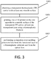
- FIG. 3 is a flowchart of a method of manufacturing an optical lens using an FDM 3-D printer and injection over-molding in accordance with exemplary aspects of the disclosure.
- the method of manufacturing an optical lens includes, S301, obtaining a transparent thermoplastic (TP) carrier with at least one smooth surface, S303, printing, via a FDM 3-D printer on the side opposite to the at least one smooth surface of the transparent TP carrier, at least one transparent layer using a thermoplastic filament, each transparent layer having a predetermined light filtering property, to form a functional layer, and, S307, performing an injection over-molding process to fuse bond the functional layer to a thermoplastic substrate to form the optical lens.
- TP transparent thermoplastic
- FIG. 4 is a schematic diagram of a system for manufacturing an optical lens using a FDM 3-D printer and injection over-molding in accordance with exemplary aspects of the disclosure.
- a filament spool 101 of thermoplastic (TP) filament 403 is supplied to an extruder 105, heated in a heater end 107, and through a nozzle 109 to print a functional layer 420 on the TP carrier 410.
- a transparent TP carrier 410 is flat with a smooth surface on at least the front side (i.e., side facing away from the nozzle 109) is obtained.
- An FDM 3-D printer prints on the back side of the carrier 410 a transparent layer 420 using a TP filament 403.
- the TP filament 403 may have specific light filters such as blue cut (BCT), color enhancement, photochromic (PhCh), and NIR cut to prepare a functional wafer 413.
- the functional layer 413 may be thermally formed into a lens shape for desired optical properties.
- This functional wafer 413, or 419 can be used with a conventional injection over-molding process 415, as illustrated in FIG. 9 , to produce an optical lens 417 with specific light filtering functions.
- TP carrier 410 can be made of TP film which itself has specific light filters to introduce additional functions.
- the filament 403 for printing the functional layer 420 and the TP carrier 410 be made of either the same material or of materials compatible to each other to guarantee good bonding and optical clarity of the functional layer/carrier interface of the resulting wafer 413.
- same filament and carrier materials include but not limited to polycarbonate (PC), alicyclic polycarbonate copolymer, poly(methyl methacrylate) (PMMA), poly(methyl methacrylimide) (PMMI), polyamide (PA), copyester, cellulose triacetate (TAC), thermoplastic polyurethane (TPU), and cyclic olefin copolymer (COC).
- Examples of dislike filament/carrier pairs include but not limited to PMMA/PC, Copolyester/PC, Polyester Alloy/PC, and Ali-cyclic Polycarbonate/PC.
- PMMA include Evonik ACRYLITE®, Arkema Altuglas®, and ChiMei ACRYREX®.
- PMMI include Evonik ACRYMID®.
- Copolyester including Eastman TRITANTM and SK Chemical Ecozen®.
- Non limiting examples of polyester alloy include Sabic XYLEXTM.
- Non alicyclic polycarbonate include Mitsubishi Chemical Corporation DURABIOTM and Teijin Planext®.
- PC include Sabic LexanTM, Teijin Panlite®, and Covestro Makrolon®.
- the lens material and the outmost layer of the back of the functional wafer 413 may be the same or compatible to guarantee good bonding and good clarity of the resulting optical lens.
- the above-mentioned examples of filament and carrier materials are also applicable in the case of lens materials.
- FIG. 5 is a schematic diagram of an injection over-molding process.
- An injection over-molding process 415 is used for integrating a functional wafer onto a thermoplastic lens. The whole process takes place at a constant cavity temperature (T cavity ) that is holding substantially below the glass transition temperature of the functional wafer material (T g , wafer).
- T cavity a constant cavity temperature
- the functional wafer 413 is inserted into the mold.
- the mold is closed.
- molten lens material 520 is injected into the mold and the lens material 520 is fuse-bonded to the functional wafer 413.
- the lens 417 is ejected from the mold.
- the process flow may begin with a 3-layer flat laminate with smooth surfaces on at least one side as a carrier 410 to prepare a functional wafer 413 with FDM 3-D printing.
- Typical examples of laminates include PC/PVA/PC and TAC/PVA/TAC polarizing laminates, PC/PU/PC and PC/TPU/PC photochromic laminates, PC/MOF (multi-layer optical film)/PC polarizing and/or blue cut and/or mirror laminates.
- PC/PVA/PC and TAC/PVA/TAC polarizing laminates PC/PU/PC and PC/TPU/PC photochromic laminates
- PC/MOF multi-layer optical film
- PC polarizing and/or blue cut and/or mirror laminates are examples of laminates, especially PVA polarizing or MOF, often possess functions that are difficult to achieve through 3D printing alone. By combining with FDM 3-D printing, extra functions can be added to such laminates without having to modify the constituent layers.
- a color enhancement layer can be printed on a PC/PVA/PC polarizing carrier to produce a polarizing wafer with color enhancement function.
- a similar method can be used to provide a color enhancement photochromic wafer by printing a color enhancement layer on a PC/PU/PC carrier.
- the transparent TP carrier is a polarizing laminate of multiple layers, where two or more of the layers are made of different materials.
- Polarizing laminates include, but are not limited to, polycarbonate (PC) /polyvinyl alcohol (PVA)/PC, cellulose triacetate (TAC)/PVA/TAC, polyamide (PA)/PVA/PA, cyclic olefin copolymer (COC)/PVA/COC, thermoplastic polyurethane (TPU)/PVA/TPU, and PC/multi-layer optical film (MOF)/PC.
- PC polycarbonate
- PVA polyvinyl alcohol
- TAC cellulose triacetate
- PA polyamide
- COC cyclic olefin copolymer
- TPU thermoplastic polyurethane
- MOF multi-layer optical film
- the transparent TP carrier is a photochromic laminate of multiple layers, where two or more of the layers are made of different materials.
- Photochromatic laminates include, but are not limited to, polycarbonate (PC)/polyurethane (PU)/PC, PC/polyether block amide (PEBA)/PC, cellulose triacetate (TAC)/PU/TAC, TAC/PEBA/TAC, polyamide (PA)/PU/PA, PA/PEBA/PA, cyclic olefin copolymer (COC)/PU/COC, COC/PEBA/COC, and thermoplastic polyurethane (TPU)/PU/TPU, and TPU/PEBA/TPU.
- PC polycarbonate
- PEBA PC/polyether block amide
- TAC/PEBA/TAC cellulose triacetate
- PA polyamide
- PA PA/PEBA/PA
- COC/PEBA/COC cyclic olefin copolymer
- TPU thermoplastic polyurethan
- FIG. 6 is a flowchart of the method of FIG. 3 including printing transparent layers in accordance with exemplary aspects of the disclosure.
- several layers of different light filters can be printed on the TP carrier 410 to produce a wafer 413 of multiple-functions.
- the FDM 3-D printer prints several transparent layers 420, where each transparent layer has a different light filtering property to form a multi-functional layer.
- FIG. 7 is a flowchart of the method of FIG. 3 including heating the TP carrier to a temperature below the glass transition temperature.
- T carrier a temperature that is less than 50°C below its glass transition temperature (T g , carrier), i.e., 0 ⁇ T g , carrier - T carrier ⁇ 50°C, and more preferably, 5°C ⁇ T g , carrier - T carrier ⁇ 30°C.
- T carrier glass transition temperature
- One advantage of present disclosure is that conventional injection over-molding process with a constant mold temperature is used, which is far less complex in mold design and much shorter in cycle comparing to heat/cool processes. Further, supplementary and/or complementary functions can be added to an existing functional carrier, which significantly shortens the time and reduces the cost to develop a new functional wafer. And, as filament extrusion and FDM 3-D printing in general are performed under lower temperature, lower shear, and shorter residence time for the materials than injection molding processes, the present approach is more suitable for preparing functional wafers with heat sensitive dyes/filters than injection molding.
- the FDM may 3D print specific patterns.
- Specific patterns may be used for writing some data linked to the lens manufacturing, using for instance IR absorbing dyes in the FDM deposited material.
- Specific patterns may also include micro lenses, a bifocal lens, a trifocal lens, and a progressive lens.
- FIG. 8 is a flowchart of the method of FIG. 3 including printing a transparent layer as a grid of diffusing dots.
- a grid made of a set of diffusing dots may be printed, as a solution to reduce contrast in the lens periphery (for example, in order to slow down myopia evolution for children, see US 2011/0313058 ).
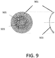
- FIG. 9 illustrates micro lenses arrayed onto a single vision spectacle lens.
- the set of diffusing dots may be micro lenses, which are typically on the order of a tenth of a millimeter in diameter to about 1.1 millimeter in diameter, and about 1 micron in height. Refractive power is at the center 905 of the lens 901, while the micro lenses form an array 903 as the specific pattern.
- the refractive index (RI) of the FDM material needs to be different from the refractive index of the injected lens material to create optical scattering.
- RI refractive index
- using dots of 0.3mm thickness and 0.3mm width or diameter, having a refractive index difference ⁇ RI 0.01 will be enough to provide optical scattering ( 0.3mmx0.01 >> wavelength of visible light).
- an FDM filament material having a scattering property may be added.
- This material may be PC mixed with pigments having a size between 100nm and 10 ⁇ m.
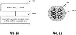
- FIG. 10 is a flowchart of the method of FIG. 3 including incorporating a specific pattern.
- the transparent layer may be printed as a specific geometric pattern.
- FIG. 11 illustrates a functional wafer with a specific geometric pattern in accordance with exemplary aspects of the disclosure.
- a wafer 1101 includes a deposition via FDM of a specific geometric pattern 1103 for scattering light.
- the specific geometric pattern is a set of rings, each ring being concentric, and made of joint circular shapes having 0.3mm or less diameter and RI of the TP carrier ⁇ RI of the FDM patterned material.
- a color-enhancing polarizing wafer and lens was manufactured.
- a 650 ⁇ m thick PC/PVA/PC neutral gray polarizing laminate with 35% transmittance from Onbitt was die-cut into a ⁇ 76mm round carrier.
- Sabic Lexan® OQ3820 is a UV-stabilized polycarbonate (PC) grade for ophthalmic lenses. This PC resin has a glass transition temperature of 145°C and a UV-cut about 380nm as measured through a 2mm thick lens. OQ3820 PC resin was compounded with two color enhancing dyes having absorption peaks around 495nm and 585nm, respectively, and then extruded into a ⁇ 1.75mm filament.
- PC polycarbonate
- a 0.1mm thick color-enhancing layer was then printed onto the PC/PVA/PC polarizing carrier with an FDM 3-D printer in a heated chamber maintained at 120°C to produce a color-enhancing polarizing wafer.
- the resulting flat wafer had a rough surface on the 3D printed side but a smooth surface on the opposite face.
- the wafer was applied in the injection over-mold process illustrated in FIG. 5 with the smooth side facing the concave insert and the rough color-enhancing layer facing the melt using OQ3820 PC resin as the lens material with the key parameters listed below: Concave insert Steel, ⁇ 76mm, and R353.3mm Convex insert Steel, ⁇ 76mm, and R88.3mm Lens material Sabic Lexan® OQ3820 PC Carrier PC/PVA/PC 35%T polarizer from Onbitt Color-enhancing layer Sabic Lexan® OQ3820 PC + 2 color-enhancing dyes FDM printed wafer geometry Flat, ⁇ 76mm, thickness 0.75mm T g, lens 145°C T g, wafer 145°C Melt temperature (T melt ) 260°C T cavity 120°C
- the resulting 1.50 base semi-finished (SF) lens 10mm in thickness, was optically transparent with smooth front and back surfaces and showed both polarizing and color enhancement functions.
- Sabic Lexan® OQ3820 is a UV-stabilized polycarbonate (PC) grade for ophthalmic lenses. This PC resin has a glass transition temperature of 145°C and a UV-cut about 380nm as measured through a 2mm thick lens. OQ3820 PC resin was compounded with 1.0% of Tinuvin® 326 UV absorber from BASF and extruded into ⁇ 1.75mm filaments.
- PC polycarbonate
- a 0.25mm thick layer was then printed onto said PC carrier with an FDM 3-D printer in a heated chamber maintained at 120°C to produce a blue cut wafer.
- the resulting flat wafer had a rough surface on the 3D printed side but a smooth surface on the opposite face.
- the wafer was applied in the injection over-mold process illustrated in FIG. 4 with the smooth side facing the concave insert and the rough blue cut layer facing the melt using OQ3820 PC resin as the lens material with the key parameters listed below: Concave insert Steel, ⁇ 76mm, and R353.3mm Convex insert Steel, ⁇ 76mm, and R88.3mm Lens material Sabic Lexan® OQ3820 PC Carrier material PC Blue cut layer Sabic Lexan® OQ3820 PC + 1.0% BASF Tinuvin 326 FDM printed wafer geometry Flat, ⁇ 76mm, thickness 0.5mm T g, lens 145°C T g, wafer 150°C Melt temperature (T melt ) 260°C T cavity 120°C
- the resulting 1.50 base semi-finished (SF) lens 10mm in thickness, not only was optically transparent with smooth front and back surfaces but also gave a UV-cut about 402nm after surfacing to 2mm plano.
- the blue cut performance BVC B' was measured to be about 30%.
- FIG. 12 illustrates a process flow of making a functional lens using a functional wafer by FDM 3-D printing of thermoplastic (TP) functional layer(s) on a curved single-layer TP carrier.
- TP thermoplastic
- a curved and transparent TP carrier 1210 with a smooth surface on the back side, or on both sides is used with an FDM 3-D printer to print on the concave side of the carrier 1210 a transparent layer 1220 using a TP filament 403 having specific light filters such as blue cut (BCT), color enhancement, photochromic (PhCh), and NIR cut to prepare a functional wafer 1213.
- This functional wafer 1213 can then be used with a conventional injection over-molding process 415 as illustrated in FIG. 5 to produce an optical lens 417 with specific light filtering functions.
- BCT blue cut
- PhCh photochromic
- NIR cut NIR cut
- the carrier 1210 can be made of TP film with specific light filters to introduce more functionality.
- the FDM 3-D printer for printing on the curved TP carrier 1210 may be a type of 3-D printer particularly arranged for printing on surfaces other than flat surfaces.
- a specialized 3-D printer may include control over the angle of the nozzle 109 such that the nozzle is continuously adjusted to face a direction that is perpendicular to the tangent of the curved surface.
Abstract
Description
- The present disclosure is directed to a technique utilizing additive techniques for manufacturing a functional wafer that is suitable for producing an optical lens with a common injection over-molding process. For instance, an FDM 3-D printing process using a smooth thermoplastic carrier is proposed to produce a wafer with light filtering functions.
- The "background" description provided herein is for the purpose of generally presenting the context of the disclosure. Work of the presently named inventors, to the extent it is described in this background section, as well as aspects of the description which may not otherwise qualify as prior art at the time of filing, are neither expressly or impliedly admitted as prior art against the present invention.
- Corrective lenses including glasses and contact lenses are used to treat refractive errors in eyes such as myopia, hypermetropia, astigmatism, and prebyopia. Glasses are worn on the face a short distance in front of the eye. Contact lenses are worn directly on the surface of the eye.
- Materials for lenses generally include glass and plastics. Glass lenses have become less common owing to their relatively high weight compared to plastic lenses. Plastic lenses are currently the most commonly prescribed lens, owing to their relative safety, low cost, ease of production, and high optical quality. The main drawbacks of many types of plastic lenses are the ease by which a lens can be scratched, and the limitations and costs of producing higher-index lenses. Polycarbonate is lighter weight than normal plastic. It blocks UV rays, is shatter resistant, and is used in sports glasses and glasses for children and teenagers. Because polycarbonate is soft and will scratch easily, scratch resistant coatings are typically applied after shaping and polishing of the lens.
- Fused Deposition Modeling ™ (FDM; sometime also referred to as Fused Filament Fabrication or FFF) is a cost-effective way of producing custom three dimensional (3-D) thermoplastic parts and prototypes.
FIG. 1 is a schematic diagram of an FDM 3-D printer. Afilament spool 101 containingfilament 103 is supplied to anextruder 105, heated in aheater end 107, and fed through anozzle 109 to produce apart 111 on aprinting bed 113. - The FDM 3-D printer also includes a programmable controller. The programmable controller controls movement of the
nozzle 109 in the planar X-Y direction and applies layers by moving in the Z-direction. In addition, the programmable controller controls the ejection of the heated filament. By controlling the movement of the nozzle and ejection of the heated filament, various patterns may be formed at each level in the X-Y plane of a layer, and application of layers in the Z-direction allows for forming various 3-D shapes. In addition, filament materials may be changed to produce layers of different materials. - A major disadvantage of FDM 3-D printing is its inability to produce at a fine enough resolution sufficient to achieve components of optical quality. The layering method of FDM results in many rigid edges (or sometimes small holes) on the surface of the part (see FDM printed
functional wafer 201 inFIG. 2 ) that strongly scatter light leading to a rough and non-transparent appearance. Further, the layer adhesion mechanism makes FDM components inherently anisotropic and poor in impact strength. Hence, FDM 3-D printing at present time is generally perceived in the optical industry as not being suitable for use in optical lens production. - A first aspect is a method of manufacturing an optical lens. The method includes obtaining a transparent thermoplastic (TP) carrier with at least one smooth surface; printing, via a 3-D printer on the side opposite to the at least one smooth surface of the transparent TP carrier, at least one transparent layer using a thermoplastic filament, each transparent layer having a predetermined light filtering property, thereby forming a functional layer; and performing an injection over-molding process to fuse bond the functional layer to a thermoplastic substrate thereby forming the optical lens.
- In a second aspect, the printing includes printing, via the 3-D printer, a plurality of transparent layers, each transparent layer having a different light filtering property to form a multi-functional layer, in which the light filtering property is one of a group consisting of ultraviolet (UV) cut, blue cut, color enhancement, photochromic, and near infrared (NIR) cut.
- In a third aspect, the transparent TP carrier has at least one predetermined light filtering property.
- In a fourth aspect, the thermoplastic filament includes a filament material that is compatible with a material of the transparent TP carrier in order to strengthen bonding of the transparent layer to the transparent TP carrier.
- In a fifth aspect, the filament material is selected from a group consisting of polycarbonate (PC), alicyclic polycarbonate copolymer, poly(methyl methacrylate) (PMMA), poly(methyl methacrylimide) (PMMI), polyamide (PA), polyester, copolyester, polysulfone (PSU), cellulose triacetate (TAC), thermoplastic polyurethane (TPU), and cyclic olefin copolymer (COC).
- In a sixth aspect, the thermoplastic substrate has a material that is compatible with a material of an outmost layer of the functional layer in order to strengthen bonding of the thermoplastic substrate to the functional layer.
- In a seventh aspect, the transparent TP carrier is a polarizing laminate of a plurality of layers, wherein two or more of the layers are of different materials selected from a group consisting of polycarbonate (PC), polyvinyl alcohol (PVA), cellulose triacetate (TAC), polyamide (PA), cyclic olefin copolymer (COC), thermoplastic polyurethane (TPU), and multi-layer optical film (MOF).
- In an eighth aspect, the transparent TP carrier is a photochromic laminate of a plurality of layers, wherein two or more of the layers are of different materials selected from a group consisting of polycarbonate (PC), polyurethane (PU), polyether block amide (PEBA), cellulose triacetate (TAC), polyamide (PA), cyclic olefin copolymer (COC), and thermoplastic polyurethane (TPU).
- In a ninth aspect, the printing further includes heating the TP carrier to a temperature (Tcarrier) that is less than 50°C below its glass transition temperature (Tg, carrier).
- In a tenth aspect, during the printing, heating the TP carrier such that 0°C < Tg, carrier - Tcarrier ≤ 50°C.
- In an eleventh aspect, during the printing, heating the TP carrier such that 5°C ≤ Tg, carrier - Tcarrier ≤ 30°C.
- In a twelfth aspect, the printing further includes incorporating a specific pattern into the at least one transparent layer.
- In a thirteenth aspect, the specific pattern includes data regarding the lens manufacturer and is incorporated using IR absorbing dyes.
- In a fourteenth aspect, the at least one transparent layer is printed as a grid made of a set of diffusing dots having different refractive index than that of the thermoplastic substrate.
- In a fifteenth aspect, the at least one transparent layer is printed as a grid made of a set of light scattering dots having size between 100nm and 10µm.
- The foregoing general description of the illustrative embodiments and the following detailed description thereof are merely exemplary aspects of the teachings of this disclosure, and are not restrictive.
- A more complete appreciation of this disclosure and many of the attendant advantages thereof will be readily obtained as the same becomes better understood by reference to the following detailed description when considered in connection with the accompanying drawings, wherein:
-
FIG. 1 is a schematic diagram of a FDM 3-D printer; -
FIG. 2 is a FDM 3-D printed functional wafer; -
FIG. 3 is a flowchart of a method of manufacturing an optical lens using a FDM 3-D printer and injection over-molding in accordance with exemplary aspects of the disclosure; -
FIG. 4 is a schematic diagram of a system for manufacturing an optical lens using a FDM 3-D printer and injection over-molding in accordance with exemplary aspects of the disclosure; -
FIG. 5 is a schematic diagram of an injection over-molding process; -
FIG. 6 is a flowchart of the method ofFIG. 3 including printing transparent layers in accordance with exemplary aspects of the disclosure; -
FIG. 7 is a flowchart of the method ofFIG. 3 including heating the TP carrier to a temperature below the glass transition temperature; -
FIG. 8 is a flowchart of the method ofFIG. 3 including printing a transparent layer in a pattern of a grid of diffusing dots; -
FIG. 9 illustrates micro lenses arrayed onto a single vision spectacle lens; -
FIG. 10 is a flowchart of the method ofFIG. 3 including incorporating a specific geometric pattern; -
FIG. 11 illustrates a functional wafer with a specific pattern in accordance with exemplary aspects of the disclosure; and -
FIG. 12 is a schematic diagram of a system for manufacturing an optical lens using a FDM 3-D printer and injection over-molding in accordance with exemplary aspects of the disclosure. - In the drawings, like reference numerals designate identical or corresponding parts throughout the several views. Further, as used herein, the words "a," "an" and the like generally carry a meaning of "one or more," unless stated otherwise. The drawings are generally drawn to scale unless specified otherwise or illustrating schematic structures or flowcharts.
- Furthermore, the terms "approximately," "approximate," "about," and similar terms generally refer to ranges that include the identified value within a margin of 20%, 10%, or preferably 5%, and any values therebetween.
- 3D printing offers benefits such as being more cost effective for small volumes and quick prototyping tasks. FDM may be used to quickly and cost effectively produce a functional wafer from a thermoplastic filament having specific dyes and/or filters such as UV cut, blue cut, NIR cut, color enhancement, and photochromic.
- One possible approach to using FDM for forming optical quality parts may be to integrate a functional wafer onto the front surface of an ophthalmic lens by conventional injection over-molding process (or film insert molding process). In this approach, during the conventional injection over-molding process, the front surface (convex surface) of the functional wafer is in contact with the cavity wall (concave insert surface) of the ophthalmic lens at a temperature well below its glass transition temperature Tg. The glass transition temperature characterizes a second order transition of amorphous polymers from brittle, glassy solids to viscous or rubber-like substances. The cavity temperature Tcavity in the injection mold must be lower than the glass transition temperature of the wafer Tg, wafer so that the functional wafer holds its shape when being inserted into the cavity. Further, the cavity temperature Tcavity must be lower than the glass transition temperature of the lens material (Tg, lens) so the resulting lens is in a solid form that is rigid enough to be ejected without deformation. In this approach, Tcavity <= Tg, lens -20 (°C). Moreover, the wafer material and the lens material should be the same in order to guarantee compatibility between the wafer and the lens for good bonding. In this case, Tg, wafer = Tg, lens.
- However using this approach, even though the back surface (concave surface) of the wafer would be melted by the molten lens material and become an integral part of the resulting lens, the front surface would remain solid and keep its surface textures throughout the whole injection over-molding process. Consequentially, the surface of an ophtalmic lens integrating a functional wafer produced by FDM 3-D printing would not be smooth.
- It is one object of the present disclosure to describe a method that uses an FDM 3-D printer to produce a functional wafer for producing an optical lens. In one aspect, a functional wafer printed by FDM 3-D printing is used with a conventional injection over-molding process to produce an optical lens.
- A reason that a conventional injection over-molding process using a FDM 3-D printed functional wafer has not been able to achieve a lens of optical quality is because the front surface of the functional wafer is kept at a temperature well below its glass transition temperature Tg and thus remains solid throughout the whole process. It has been determined that this problem can be overcome, at least, by first obtaining a single or multi-layer functional thermoplastic carrier with at least a smooth front surface, then 3D print additional functional layer(s) fuse-bonded onto a back surface of the carrier. At least the front surface of the thermoplastic carrier is smooth. The resulting 3D printed article would preserve the smooth front surface of the functional carrier while adding new functionality through the additional layer(s). The 3D printed article can be used as a functional wafer with conventional injection over-molding to produce an optical article with smooth surfaces.
- In some embodiments, a flat, multi-layer, transparent thermoplastic (TP) carrier is obtained and an FDM 3-D printer is used to print a transparent layer on a side of the carrier. The transparent layer may be printed using a TP filament having specific light filters such as blue cut (BCT), color enhancement, photochromatic (PhCh), and Near Infrared (NIR) light cut to prepare a functional wafer. This functional wafer can then be used with a conventional injection over-molding process to produce an optical lens with the specific light filtering functions. In some aspects, several layers of different light filters can be printed on the carrier to prepare a wafer of multiple-functions such as PhCh/BCT, BCT/NIR cut, PhCh/BCT/NIR cut, and other light filtering functions.
-
FIG. 3 is a flowchart of a method of manufacturing an optical lens using an FDM 3-D printer and injection over-molding in accordance with exemplary aspects of the disclosure. The method of manufacturing an optical lens includes, S301, obtaining a transparent thermoplastic (TP) carrier with at least one smooth surface, S303, printing, via a FDM 3-D printer on the side opposite to the at least one smooth surface of the transparent TP carrier, at least one transparent layer using a thermoplastic filament, each transparent layer having a predetermined light filtering property, to form a functional layer, and, S307, performing an injection over-molding process to fuse bond the functional layer to a thermoplastic substrate to form the optical lens. -
FIG. 4 is a schematic diagram of a system for manufacturing an optical lens using a FDM 3-D printer and injection over-molding in accordance with exemplary aspects of the disclosure. Afilament spool 101 of thermoplastic (TP)filament 403 is supplied to anextruder 105, heated in aheater end 107, and through anozzle 109 to print afunctional layer 420 on theTP carrier 410. In some embodiments, atransparent TP carrier 410 is flat with a smooth surface on at least the front side (i.e., side facing away from the nozzle 109) is obtained. An FDM 3-D printer prints on the back side of the carrier 410 atransparent layer 420 using aTP filament 403. TheTP filament 403 may have specific light filters such as blue cut (BCT), color enhancement, photochromic (PhCh), and NIR cut to prepare afunctional wafer 413. In some embodiments, in 419, thefunctional layer 413 may be thermally formed into a lens shape for desired optical properties. Thisfunctional wafer over-molding process 415, as illustrated inFIG. 9 , to produce anoptical lens 417 with specific light filtering functions. - In some embodiments, several layers of different light filters can be printed on the
TP carrier 410 to produce awafer 413 of multiple-functions such as PhCh/BCT, BCT/NIR cut, PhCh/BCT/NIR cut, and other optical functions. Further, theTP carrier 410 can be made of TP film which itself has specific light filters to introduce additional functions. - It is preferred that the
filament 403 for printing thefunctional layer 420 and theTP carrier 410 be made of either the same material or of materials compatible to each other to guarantee good bonding and optical clarity of the functional layer/carrier interface of the resultingwafer 413. Examples of same filament and carrier materials include but not limited to polycarbonate (PC), alicyclic polycarbonate copolymer, poly(methyl methacrylate) (PMMA), poly(methyl methacrylimide) (PMMI), polyamide (PA), copyester, cellulose triacetate (TAC), thermoplastic polyurethane (TPU), and cyclic olefin copolymer (COC). Examples of dislike filament/carrier pairs include but not limited to PMMA/PC, Copolyester/PC, Polyester Alloy/PC, and Ali-cyclic Polycarbonate/PC. Non limiting examples of PMMA include Evonik ACRYLITE®, Arkema Altuglas®, and ChiMei ACRYREX®. Non limiting examples of PMMI include Evonik ACRYMID®. Non limiting examples of Copolyester including Eastman TRITAN™ and SK Chemical Ecozen®. Non limiting examples of polyester alloy include Sabic XYLEX™. Non limiting examples of alicyclic polycarbonate include Mitsubishi Chemical Corporation DURABIO™ and Teijin Planext®. Non limiting examples of PC include Sabic Lexan™, Teijin Panlite®, and Covestro Makrolon®. - Further, to use the 3D printed
functional wafer 413 withinjection over-molding 415, the lens material and the outmost layer of the back of thefunctional wafer 413 may be the same or compatible to guarantee good bonding and good clarity of the resulting optical lens. The above-mentioned examples of filament and carrier materials are also applicable in the case of lens materials. -
FIG. 5 is a schematic diagram of an injection over-molding process. Aninjection over-molding process 415 is used for integrating a functional wafer onto a thermoplastic lens. The whole process takes place at a constant cavity temperature (Tcavity) that is holding substantially below the glass transition temperature of the functional wafer material (Tg, wafer). In 501, the mold is opened. In 503, thefunctional wafer 413 is inserted into the mold. In 505, the mold is closed. In 507,molten lens material 520 is injected into the mold and thelens material 520 is fuse-bonded to thefunctional wafer 413. In 509, thelens 417 is ejected from the mold. - In some embodiments, the process flow may begin with a 3-layer flat laminate with smooth surfaces on at least one side as a
carrier 410 to prepare afunctional wafer 413 with FDM 3-D printing. Typical examples of laminates include PC/PVA/PC and TAC/PVA/TAC polarizing laminates, PC/PU/PC and PC/TPU/PC photochromic laminates, PC/MOF (multi-layer optical film)/PC polarizing and/or blue cut and/or mirror laminates. These types of laminates, especially PVA polarizing or MOF, often possess functions that are difficult to achieve through 3D printing alone. By combining with FDM 3-D printing, extra functions can be added to such laminates without having to modify the constituent layers. For example, a color enhancement layer can be printed on a PC/PVA/PC polarizing carrier to produce a polarizing wafer with color enhancement function. A similar method can be used to provide a color enhancement photochromic wafer by printing a color enhancement layer on a PC/PU/PC carrier. - In some embodiments, the transparent TP carrier is a polarizing laminate of multiple layers, where two or more of the layers are made of different materials. Polarizing laminates include, but are not limited to, polycarbonate (PC) /polyvinyl alcohol (PVA)/PC, cellulose triacetate (TAC)/PVA/TAC, polyamide (PA)/PVA/PA, cyclic olefin copolymer (COC)/PVA/COC, thermoplastic polyurethane (TPU)/PVA/TPU, and PC/multi-layer optical film (MOF)/PC. Although these laminates are symmetrical, non-symmetrical laminates may be used as well.
- In some embodiments, the transparent TP carrier is a photochromic laminate of multiple layers, where two or more of the layers are made of different materials. Photochromatic laminates include, but are not limited to, polycarbonate (PC)/polyurethane (PU)/PC, PC/polyether block amide (PEBA)/PC, cellulose triacetate (TAC)/PU/TAC, TAC/PEBA/TAC, polyamide (PA)/PU/PA, PA/PEBA/PA, cyclic olefin copolymer (COC)/PU/COC, COC/PEBA/COC, and thermoplastic polyurethane (TPU)/PU/TPU, and TPU/PEBA/TPU. Although these laminates are symmetrical, non-symmetrical laminates may be used as well.
-
FIG. 6 is a flowchart of the method ofFIG. 3 including printing transparent layers in accordance with exemplary aspects of the disclosure. As mentioned above, several layers of different light filters can be printed on theTP carrier 410 to produce awafer 413 of multiple-functions. In S601, the FDM 3-D printer prints severaltransparent layers 420, where each transparent layer has a different light filtering property to form a multi-functional layer. -
FIG. 7 is a flowchart of the method ofFIG. 3 including heating the TP carrier to a temperature below the glass transition temperature. In particular, to promote the quality of the 3D printed layer and to enhance the bonding strength between the 3D printedfunctional layer 420 and theTP carrier 410, it is preferred, during 3D printing (S303), in S701, to heat and maintain the carrier at a temperature (Tcarrier) that is less than 50°C below its glass transition temperature (Tg, carrier), i.e., 0 < Tg, carrier - Tcarrier ≤ 50°C, and more preferably, 5°C ≤ Tg, carrier - Tcarrier ≤ 30°C. Such temperature condition can be achieved by using a heated printing bed and/or performing the 3D printing in a heated chamber. - One advantage of present disclosure is that conventional injection over-molding process with a constant mold temperature is used, which is far less complex in mold design and much shorter in cycle comparing to heat/cool processes. Further, supplementary and/or complementary functions can be added to an existing functional carrier, which significantly shortens the time and reduces the cost to develop a new functional wafer. And, as filament extrusion and FDM 3-D printing in general are performed under lower temperature, lower shear, and shorter residence time for the materials than injection molding processes, the present approach is more suitable for preparing functional wafers with heat sensitive dyes/filters than injection molding.
- In some embodiments, rather than add a uniform layer, the FDM may 3D print specific patterns. Specific patterns may be used for writing some data linked to the lens manufacturing, using for instance IR absorbing dyes in the FDM deposited material. Specific patterns may also include micro lenses, a bifocal lens, a trifocal lens, and a progressive lens.
- In one embodiment, specific patterns may be formed for purposes of myopia control.
FIG. 8 is a flowchart of the method ofFIG. 3 including printing a transparent layer as a grid of diffusing dots. In S801, a grid made of a set of diffusing dots may be printed, as a solution to reduce contrast in the lens periphery (for example, in order to slow down myopia evolution for children, seeUS 2011/0313058 ).FIG. 9 illustrates micro lenses arrayed onto a single vision spectacle lens. The set of diffusing dots may be micro lenses, which are typically on the order of a tenth of a millimeter in diameter to about 1.1 millimeter in diameter, and about 1 micron in height. Refractive power is at thecenter 905 of thelens 901, while the micro lenses form anarray 903 as the specific pattern. - In this embodiment, the refractive index (RI) of the FDM material needs to be different from the refractive index of the injected lens material to create optical scattering. For instance, using dots of 0.3mm thickness and 0.3mm width or diameter, having a refractive index difference ΔRI=0.01 will be enough to provide optical scattering ( 0.3mmx0.01 >> wavelength of visible light). Smaller dots may be preferable to increase the scattering angle of the dots. For instance, a 0.2mm diameter will scatter light on (3/2)2 = 2.25 larger angular area.
- In one embodiment, an FDM filament material having a scattering property may be added. This material may be PC mixed with pigments having a size between 100nm and 10µm.
- In some embodiments, other patterns may be printed.
FIG. 10 is a flowchart of the method ofFIG. 3 including incorporating a specific pattern. In S1001, the transparent layer may be printed as a specific geometric pattern.FIG. 11 illustrates a functional wafer with a specific geometric pattern in accordance with exemplary aspects of the disclosure. InFIG. 11 , awafer 1101 includes a deposition via FDM of a specificgeometric pattern 1103 for scattering light. In particular, the specific geometric pattern is a set of rings, each ring being concentric, and made of joint circular shapes having 0.3mm or less diameter and RI of the TP carrier ≠ RI of the FDM patterned material. - As one experimental implementation, a color-enhancing polarizing wafer and lens was manufactured. In the implementation, a 650µm thick PC/PVA/PC neutral gray polarizing laminate with 35% transmittance from Onbitt was die-cut into a ∅76mm round carrier.
- Sabic Lexan® OQ3820 is a UV-stabilized polycarbonate (PC) grade for ophthalmic lenses. This PC resin has a glass transition temperature of 145°C and a UV-cut about 380nm as measured through a 2mm thick lens. OQ3820 PC resin was compounded with two color enhancing dyes having absorption peaks around 495nm and 585nm, respectively, and then extruded into a ∅1.75mm filament.
- Using the filament, a 0.1mm thick color-enhancing layer was then printed onto the PC/PVA/PC polarizing carrier with an FDM 3-D printer in a heated chamber maintained at 120°C to produce a color-enhancing polarizing wafer. The resulting flat wafer had a rough surface on the 3D printed side but a smooth surface on the opposite face.
- To produce a polarizing lens with color enhancement function, the wafer was applied in the injection over-mold process illustrated in
FIG. 5 with the smooth side facing the concave insert and the rough color-enhancing layer facing the melt using OQ3820 PC resin as the lens material with the key parameters listed below:Concave insert Steel, ∅76mm, and R353.3mm Convex insert Steel, ∅76mm, and R88.3mm Lens material Sabic Lexan® OQ3820 PC Carrier PC/PVA/PC 35%T polarizer from Onbitt Color-enhancing layer Sabic Lexan® OQ3820 PC + 2 color-enhancing dyes FDM printed wafer geometry Flat, ∅76mm, thickness 0.75mm Tg, lens 145°C Tg, wafer 145°C Melt temperature (Tmelt) 260°C Tcavity 120°C - The resulting 1.50 base semi-finished (SF) lens, 10mm in thickness, was optically transparent with smooth front and back surfaces and showed both polarizing and color enhancement functions.
- As a second experimental implementation, a blue cut wafer and lens was manufactured.
- A 250µm thick commercially available clear PC film with a total transmittance of 91% and a UV cut-off < 300nm was die-cut into a ∅76mm round carrier.
- Sabic Lexan® OQ3820 is a UV-stabilized polycarbonate (PC) grade for ophthalmic lenses. This PC resin has a glass transition temperature of 145°C and a UV-cut about 380nm as measured through a 2mm thick lens. OQ3820 PC resin was compounded with 1.0% of Tinuvin® 326 UV absorber from BASF and extruded into ∅1.75mm filaments.
- Using the filament, a 0.25mm thick layer was then printed onto said PC carrier with an FDM 3-D printer in a heated chamber maintained at 120°C to produce a blue cut wafer. The resulting flat wafer had a rough surface on the 3D printed side but a smooth surface on the opposite face.
- To produce a blue cut lens, the wafer was applied in the injection over-mold process illustrated in
FIG. 4 with the smooth side facing the concave insert and the rough blue cut layer facing the melt using OQ3820 PC resin as the lens material with the key parameters listed below:Concave insert Steel, ∅76mm, and R353.3mm Convex insert Steel, ∅76mm, and R88.3mm Lens material Sabic Lexan® OQ3820 PC Carrier material PC Blue cut layer Sabic Lexan® OQ3820 PC + 1.0% BASF Tinuvin 326 FDM printed wafer geometry Flat, ∅76mm, thickness 0.5mm Tg, lens 145°C Tg, wafer 150°C Melt temperature (Tmelt) 260°C Tcavity 120°C - The resulting 1.50 base semi-finished (SF) lens, 10mm in thickness, not only was optically transparent with smooth front and back surfaces but also gave a UV-cut about 402nm after surfacing to 2mm plano. In addition, the blue cut performance BVC B' was measured to be about 30%.
-
FIG. 12 illustrates a process flow of making a functional lens using a functional wafer by FDM 3-D printing of thermoplastic (TP) functional layer(s) on a curved single-layer TP carrier. - In
FIG. 12 , a curved andtransparent TP carrier 1210 with a smooth surface on the back side, or on both sides, is used with an FDM 3-D printer to print on the concave side of the carrier 1210 atransparent layer 1220 using aTP filament 403 having specific light filters such as blue cut (BCT), color enhancement, photochromic (PhCh), and NIR cut to prepare afunctional wafer 1213. Thisfunctional wafer 1213 can then be used with a conventional injectionover-molding process 415 as illustrated inFIG. 5 to produce anoptical lens 417 with specific light filtering functions. In some embodiments, similar to the above case inFIG. 4 , several layers of different light filters can be printed on thecarrier 1210 to have awafer 1213 of multi-functions such as PhCh/BCT, BCT/NIR cut, PhCh/BCT/NIR cut, etc. Further, thecarrier 1210 can be made of TP film with specific light filters to introduce more functionality. - In some embodiments, the FDM 3-D printer for printing on the
curved TP carrier 1210 may be a type of 3-D printer particularly arranged for printing on surfaces other than flat surfaces. For example, a specialized 3-D printer may include control over the angle of thenozzle 109 such that the nozzle is continuously adjusted to face a direction that is perpendicular to the tangent of the curved surface. - (1) A method of manufacturing an optical lens, including:
- obtaining a transparent thermoplastic (TP) carrier with at least one smooth surface;
- printing, via a 3-D printer on the side opposite to the at least one smooth surface of the transparent TP carrier, at least one transparent layer using a thermoplastic filament, each transparent layer having a predetermined light filtering property, thereby forming a functional layer; and
- performing an injection over-molding process to fuse bond the functional layer to a thermoplastic substrate thereby forming the optical lens.
- (2) The method according to (1), in which the printing includes:
- printing, via the 3-D printer, a plurality of transparent layers, each transparent layer having a different light filtering property to form a multi-functional layer,
- wherein the light filtering property is one of a group consisting of ultraviolet (UV) cut, blue cut, color enhancement, photochromic, and near infrared (NIR) cut.
- (3) The method according (1) or (2), in which the transparent TP carrier has at least one predetermined light filtering property.
- (4) The method according to any of (1) to (3), in which the thermoplastic filament includes a filament material that is compatible with a material of the transparent TP carrier in order to strengthen bonding of the transparent layer to the transparent TP carrier.
- (5) The method according to any of (1) to (4), in which the filament material is selected from a group consisting of polycarbonate (PC), alicyclic polycarbonate copolymer, poly(methyl methacrylate) (PMMA), poly(methyl methacrylimide) (PMMI), polyamide (PA), polyester, copolyester, polysulfone (PSU), cellulose triacetate (TAC), thermoplastic polyurethane (TPU), and cyclic olefin copolymer (COC).
- (6) The method according to any of (1) to (5), in which the thermoplastic substrate has a material that is compatible with a material of an outmost layer of the functional layer in order to strengthen bonding of the thermoplastic substrate to the functional layer.
- (7) The method according to any of (1) to (6), in which the transparent TP carrier is a polarizing laminate of a plurality of layers, wherein two or more of the layers are of different materials selected from a group consisting of polycarbonate (PC), polyvinyl alcohol (PVA), cellulose triacetate (TAC), polyamide (PA), cyclic olefin copolymer (COC), thermoplastic polyurethane (TPU), and multi-layer optical film (MOF).
- (8) The method according to any of (1) to (7), in which the transparent TP carrier is a photochromic laminate of a plurality of layers, wherein two or more of the layers are of different materials selected from a group consisting of polycarbonate (PC), polyurethane (PU), polyether block amide (PEBA), cellulose triacetate (TAC), polyamide (PA), cyclic olefin copolymer (COC), and thermoplastic polyurethane (TPU).
- (9) The method according to any of (1) to (8), in which the printing further comprises heating the TP carrier to a temperature (Tcarrier) that is less than 50°C below its glass transition temperature (Tg, carrier).
- (10) The method according to (9), in which, during the printing, heating the TP carrier such that 0°C < Tg, carrier - Tcarrier ≤ 50°C.
- (11) The method according to (10), in which, during the printing, heating the TP carrier such that 5°C ≤ Tg, carrier - Tcarrier ≤ 30°C.
- (12) The method according to any of (1) to (11), in which the printing further comprises incorporating a specific pattern into the at least one transparent layer.
- (13) The method according to (12), in which the specific pattern includes data regarding the lens manufacturer and is incorporated using IR absorbing dyes.
- (14) The method according to any of (1) to (13), in which the at least one transparent layer is printed as a grid made of a set of diffusing dots having different refractive index than that of the thermoplastic substrate.
- (15) The method according to any of (1) to (14), in which the at least one transparent layer is printed as a grid made of a set of light scattering dots having size between 100nm and 10µm.
- (16) A method of manufacturing an optical lens, including:
- obtaining a curved and transparent thermoplastic (TP) carrier with smooth surfaces on both sides;
- printing, via a 3-D printer on a concave side of the curved and transparent TP carrier, at least one transparent layer using a thermoplastic filament, each transparent layer having a predetermined light filtering property, thereby forming a functional layer; and
- performing an injection over-molding process to fuse bond the functional layer to a thermoplastic substrate thereby forming the optical lens.
- (17) The method according to (16), wherein the printing includes:
- printing, via the 3-D printer, a plurality of transparent layers, each transparent layer having a different light filtering property to form a multi-functional layer,
- in which the light filtering property is one of a group consisting of ultraviolet (UV) cut, blue cut, color enhancement, photochromic, and near infrared (NIR) cut.
- (18) The method according to (16) or (17), in which the curved and transparent TP carrier has at least one predetermined light filtering property.
- (19) The method according to any of (16) to (18), in which the thermoplastic filament includes a filament material that is compatible with a material of the curved and transparent TP carrier in order to strengthen bonding of the transparent layer to the curved and transparent TP carrier.
- (20) The method according to (19), in which the filament material is selected from a group consisting of polycarbonate (PC), alicyclic polycarbonate copolymer, poly(methyl methacrylate) (PMMA), poly(methyl methacrylimide) (PMMI), polyamide (PA), polyester, copolyester, polysulfone (PSU), cellulose triacetate (TAC), thermoplastic polyurethane (TPU), and cyclic olefin copolymer (COC).
- Numerous modifications and variations of the present invention are possible in light of the above teachings. It is therefore to be understood that within the scope of the appended claims, the invention may be practiced otherwise than as specifically described herein.
Claims (15)
- A method of manufacturing an optical lens, comprising:obtaining a transparent thermoplastic (TP) carrier with at least one smooth surface;printing, via a 3-D printer on the side opposite to the at least one smooth surface of the transparent TP carrier, at least one transparent layer using a thermoplastic filament, each transparent layer having a predetermined light filtering property, thereby forming a functional layer; andperforming an injection over-molding process to fuse bond the functional layer to a thermoplastic substrate thereby forming the optical lens.
- The method according to claim 1, wherein the printing includes:printing, via the 3-D printer, a plurality of transparent layers, each transparent layer having a different light filtering property to form a multi-functional layer,wherein the light filtering property is one of a group consisting of ultraviolet (UV) cut, blue cut, color enhancement, photochromic, and near infrared (NIR) cut.
- The method according to claim 1, wherein the transparent TP carrier has at least one predetermined light filtering property.
- The method according to claim 1, wherein the thermoplastic filament includes a filament material that is compatible with a material of the transparent TP carrier in order to strengthen bonding of the transparent layer to the transparent TP carrier.
- The method according to claim 4, wherein the filament material is selected from a group consisting of polycarbonate (PC), alicyclic polycarbonate copolymer, poly(methyl methacrylate) (PMMA), poly(methyl methacrylimide) (PMMI), polyamide (PA), polyester, copolyester, polysulfone (PSU), cellulose triacetate (TAC), thermoplastic polyurethane (TPU), and cyclic olefin copolymer (COC).
- The method according to claim 1, wherein the thermoplastic substrate has a material that is compatible with a material of an outmost layer of the functional layer in order to strengthen bonding of the thermoplastic substrate to the functional layer.
- The method according to claim 1, wherein the transparent TP carrier is a polarizing laminate of a plurality of layers, wherein two or more of the layers are of different materials selected from a group consisting of polycarbonate (PC), polyvinyl alcohol (PVA), cellulose triacetate (TAC), polyamide (PA), cyclic olefin copolymer (COC), thermoplastic polyurethane (TPU), and multi-layer optical film (MOF).
- The method according to claim 1, wherein the transparent TP carrier is a photochromic laminate of a plurality of layers, wherein two or more of the layers are of different materials selected from a group consisting of polycarbonate (PC), polyurethane (PU), polyether block amide (PEBA), cellulose triacetate (TAC), polyamide (PA), cyclic olefin copolymer (COC), and thermoplastic polyurethane (TPU).
- The method according to claim 1, wherein the printing further comprises heating the TP carrier to a temperature (Tcarrier) that is less than 50°C below its glass transition temperature (Tg, carrier).
- The method according to claim 9, wherein, during the printing, heating the TP carrier such that 0°C < Tg, carrier - Tcarrier ≤ 50°C.
- The method according to claim 10, wherein, during the printing, heating the TP carrier such that 5°C ≤ Tg, carrier - Tcarrier ≤ 30°C.
- The method according to claim 1, wherein the printing further comprises incorporating a specific pattern into the at least one transparent layer.
- The method according to claim 12, wherein the specific pattern includes data regarding the lens manufacturer and is incorporated using IR absorbing dyes.
- The method according to claim 1, wherein the at least one transparent layer is printed as a grid made of a set of diffusing dots having different refractive index than that of the thermoplastic substrate.
- The method according to claim 1, wherein the at least one transparent layer is printed as a grid made of a set of light scattering dots having size between 100nm and 10µm.
Priority Applications (6)
| Application Number | Priority Date | Filing Date | Title |
|---|---|---|---|
| EP20167150.0A EP3888894A1 (en) | 2020-03-31 | 2020-03-31 | Laminate wafers containing a soft deformable inner film |
| US17/915,933 US20230147427A1 (en) | 2020-03-31 | 2021-03-31 | Functional wafers by 3d printing |
| MX2022012107A MX2022012107A (en) | 2020-03-31 | 2021-03-31 | Functional wafers by 3d printing. |
| PCT/EP2021/058511 WO2021198374A1 (en) | 2020-03-31 | 2021-03-31 | Functional wafers by 3d printing |
| CN202180024603.3A CN115335213A (en) | 2020-03-31 | 2021-03-31 | Functional membrane through 3D printing |
| EP21716185.0A EP4106983A1 (en) | 2020-03-31 | 2021-03-31 | Functional wafers by 3d printing |
Applications Claiming Priority (1)
| Application Number | Priority Date | Filing Date | Title |
|---|---|---|---|
| EP20167150.0A EP3888894A1 (en) | 2020-03-31 | 2020-03-31 | Laminate wafers containing a soft deformable inner film |
Publications (1)
| Publication Number | Publication Date |
|---|---|
| EP3888894A1 true EP3888894A1 (en) | 2021-10-06 |
Family
ID=70110120
Family Applications (2)
| Application Number | Title | Priority Date | Filing Date |
|---|---|---|---|
| EP20167150.0A Pending EP3888894A1 (en) | 2020-03-31 | 2020-03-31 | Laminate wafers containing a soft deformable inner film |
| EP21716185.0A Pending EP4106983A1 (en) | 2020-03-31 | 2021-03-31 | Functional wafers by 3d printing |
Family Applications After (1)
| Application Number | Title | Priority Date | Filing Date |
|---|---|---|---|
| EP21716185.0A Pending EP4106983A1 (en) | 2020-03-31 | 2021-03-31 | Functional wafers by 3d printing |
Country Status (5)
| Country | Link |
|---|---|
| US (1) | US20230147427A1 (en) |
| EP (2) | EP3888894A1 (en) |
| CN (1) | CN115335213A (en) |
| MX (1) | MX2022012107A (en) |
| WO (1) | WO2021198374A1 (en) |
Cited By (1)
| Publication number | Priority date | Publication date | Assignee | Title |
|---|---|---|---|---|
| WO2023156052A1 (en) | 2022-02-16 | 2023-08-24 | Carl Zeiss Vision International Gmbh | Spectacle lens to reduce the progression of myopia |
Citations (10)
| Publication number | Priority date | Publication date | Assignee | Title |
|---|---|---|---|---|
| US20040125337A1 (en) * | 2002-10-04 | 2004-07-01 | Vision-Ease | Laminated functional wafer for plastic optical elements |
| US20110313058A1 (en) | 2008-12-22 | 2011-12-22 | Jay Neitz | Method and apparatus for limiting growth of eye length |
| US20150241714A1 (en) * | 2012-09-28 | 2015-08-27 | Essilor International (Compagnie Generale D'optique) | Method for manufacturing an ophthalmic lens |
| US20150253585A1 (en) * | 2012-09-28 | 2015-09-10 | Essilor International (Compagnie Générale d'Optique) | Method for manufacturing an ophthalmic lens comprising a marking step for producing permanent technical marks on said ophthalmic lens |
| US20160003977A1 (en) * | 2013-01-10 | 2016-01-07 | Luxexcel Holding B.V. | Method of printing an optical element |
| US20160096326A1 (en) * | 2014-10-03 | 2016-04-07 | Tyco Electronics Corporation | Selective zone temperature control build plate |
| EP3495128A1 (en) * | 2017-12-06 | 2019-06-12 | Essilor International | Method of additively manufacturing an ophthalmic lens and ophthalmic lens |
| US20190324293A1 (en) * | 2015-04-15 | 2019-10-24 | Vision Ease, Lp | Ophthalmic Lens With Graded Microlenses |
| EP3579044A1 (en) * | 2018-06-08 | 2019-12-11 | Essilor International | Determining method for an ophthalmic lens with targeted transmission spectrum |
| US20200012123A1 (en) * | 2014-03-24 | 2020-01-09 | Menicon Singapore Pte Ltd. | Apparatus and methods for controlling axial growth with an ocular lens |
Family Cites Families (1)
| Publication number | Priority date | Publication date | Assignee | Title |
|---|---|---|---|---|
| EP3437845A1 (en) * | 2017-08-03 | 2019-02-06 | Essilor International | Method for making polarized and photochromic thermoplastic lenses |
-
2020
- 2020-03-31 EP EP20167150.0A patent/EP3888894A1/en active Pending
-
2021
- 2021-03-31 EP EP21716185.0A patent/EP4106983A1/en active Pending
- 2021-03-31 WO PCT/EP2021/058511 patent/WO2021198374A1/en unknown
- 2021-03-31 MX MX2022012107A patent/MX2022012107A/en unknown
- 2021-03-31 US US17/915,933 patent/US20230147427A1/en active Pending
- 2021-03-31 CN CN202180024603.3A patent/CN115335213A/en active Pending
Patent Citations (10)
| Publication number | Priority date | Publication date | Assignee | Title |
|---|---|---|---|---|
| US20040125337A1 (en) * | 2002-10-04 | 2004-07-01 | Vision-Ease | Laminated functional wafer for plastic optical elements |
| US20110313058A1 (en) | 2008-12-22 | 2011-12-22 | Jay Neitz | Method and apparatus for limiting growth of eye length |
| US20150241714A1 (en) * | 2012-09-28 | 2015-08-27 | Essilor International (Compagnie Generale D'optique) | Method for manufacturing an ophthalmic lens |
| US20150253585A1 (en) * | 2012-09-28 | 2015-09-10 | Essilor International (Compagnie Générale d'Optique) | Method for manufacturing an ophthalmic lens comprising a marking step for producing permanent technical marks on said ophthalmic lens |
| US20160003977A1 (en) * | 2013-01-10 | 2016-01-07 | Luxexcel Holding B.V. | Method of printing an optical element |
| US20200012123A1 (en) * | 2014-03-24 | 2020-01-09 | Menicon Singapore Pte Ltd. | Apparatus and methods for controlling axial growth with an ocular lens |
| US20160096326A1 (en) * | 2014-10-03 | 2016-04-07 | Tyco Electronics Corporation | Selective zone temperature control build plate |
| US20190324293A1 (en) * | 2015-04-15 | 2019-10-24 | Vision Ease, Lp | Ophthalmic Lens With Graded Microlenses |
| EP3495128A1 (en) * | 2017-12-06 | 2019-06-12 | Essilor International | Method of additively manufacturing an ophthalmic lens and ophthalmic lens |
| EP3579044A1 (en) * | 2018-06-08 | 2019-12-11 | Essilor International | Determining method for an ophthalmic lens with targeted transmission spectrum |
Cited By (2)
| Publication number | Priority date | Publication date | Assignee | Title |
|---|---|---|---|---|
| WO2023156052A1 (en) | 2022-02-16 | 2023-08-24 | Carl Zeiss Vision International Gmbh | Spectacle lens to reduce the progression of myopia |
| WO2023155984A1 (en) * | 2022-02-16 | 2023-08-24 | Carl Zeiss Vision International Gmbh | Spectacle lens to reduce the progression of myopia |
Also Published As
| Publication number | Publication date |
|---|---|
| EP4106983A1 (en) | 2022-12-28 |
| WO2021198374A1 (en) | 2021-10-07 |
| CN115335213A (en) | 2022-11-11 |
| US20230147427A1 (en) | 2023-05-11 |
| MX2022012107A (en) | 2023-01-18 |
Similar Documents
| Publication | Publication Date | Title |
|---|---|---|
| CN207752263U (en) | Stack mirrors formula eyeglass and eyewear | |
| EP1370897B1 (en) | Polarized eyewear using high impact, high optical-quality polymeric material | |
| EP1193535B1 (en) | Transparent optical article | |
| US5805336A (en) | Optical lens blank with polarizer aligned between plastic birefringent sheets | |
| KR20190025724A (en) | Glasses lens and method for making same | |
| WO1997038345A1 (en) | Lens blanks for producing prescription lenses | |
| EP1217397A2 (en) | Polarizing molded article and process for preparing the same | |
| US20030179459A1 (en) | Polarized lens of plastic lamination and the production method of the same | |
| US20230147427A1 (en) | Functional wafers by 3d printing | |
| EP1492658B1 (en) | Injection molding of lens | |
| US20230375856A1 (en) | Soft optical patch with light filtration and vision correction for ophthalmic applications | |
| EP3581976A1 (en) | Method for making a gradient color polar lens with a non-polar near vision zone | |
| JP4117657B2 (en) | Manufacturing method of laminated molding | |
| US20220276409A1 (en) | Method for Making Optical Lenses Using 3D Printed Functional Wafers | |
| EP3974163A1 (en) | Method for printing a thermoplastic film on an optical mold | |
| US20220266488A1 (en) | Injection Overmolding with Heat/Cool Cycling for Making Optical Lenses Using 3D-Printed Functional Wafers | |
| JPH09179076A (en) | Polarizing plastic lens and its production |
Legal Events
| Date | Code | Title | Description |
|---|---|---|---|
| PUAI | Public reference made under article 153(3) epc to a published international application that has entered the european phase |
Free format text: ORIGINAL CODE: 0009012 |
|
| STAA | Information on the status of an ep patent application or granted ep patent |
Free format text: STATUS: THE APPLICATION HAS BEEN PUBLISHED |
|
| AK | Designated contracting states |
Kind code of ref document: A1 Designated state(s): AL AT BE BG CH CY CZ DE DK EE ES FI FR GB GR HR HU IE IS IT LI LT LU LV MC MK MT NL NO PL PT RO RS SE SI SK SM TR |
|
| STAA | Information on the status of an ep patent application or granted ep patent |
Free format text: STATUS: REQUEST FOR EXAMINATION WAS MADE |
|
| 17P | Request for examination filed |
Effective date: 20220331 |
|
| RBV | Designated contracting states (corrected) |
Designated state(s): AL AT BE BG CH CY CZ DE DK EE ES FI FR GB GR HR HU IE IS IT LI LT LU LV MC MK MT NL NO PL PT RO RS SE SI SK SM TR |
|
| P01 | Opt-out of the competence of the unified patent court (upc) registered |
Effective date: 20230525 |