EP3888892A1 - Composite materials having reinforced access openings - Google Patents
Composite materials having reinforced access openings Download PDFInfo
- Publication number
- EP3888892A1 EP3888892A1 EP21162842.5A EP21162842A EP3888892A1 EP 3888892 A1 EP3888892 A1 EP 3888892A1 EP 21162842 A EP21162842 A EP 21162842A EP 3888892 A1 EP3888892 A1 EP 3888892A1
- Authority
- EP
- European Patent Office
- Prior art keywords
- component
- composite
- region
- induced
- plane
- Prior art date
- Legal status (The legal status is an assumption and is not a legal conclusion. Google has not performed a legal analysis and makes no representation as to the accuracy of the status listed.)
- Granted
Links
Images







Classifications
-
- B—PERFORMING OPERATIONS; TRANSPORTING
- B29—WORKING OF PLASTICS; WORKING OF SUBSTANCES IN A PLASTIC STATE IN GENERAL
- B29C—SHAPING OR JOINING OF PLASTICS; SHAPING OF MATERIAL IN A PLASTIC STATE, NOT OTHERWISE PROVIDED FOR; AFTER-TREATMENT OF THE SHAPED PRODUCTS, e.g. REPAIRING
- B29C70/00—Shaping composites, i.e. plastics material comprising reinforcements, fillers or preformed parts, e.g. inserts
- B29C70/04—Shaping composites, i.e. plastics material comprising reinforcements, fillers or preformed parts, e.g. inserts comprising reinforcements only, e.g. self-reinforcing plastics
- B29C70/06—Fibrous reinforcements only
-
- B—PERFORMING OPERATIONS; TRANSPORTING
- B64—AIRCRAFT; AVIATION; COSMONAUTICS
- B64C—AEROPLANES; HELICOPTERS
- B64C3/00—Wings
- B64C3/20—Integral or sandwich constructions
-
- B—PERFORMING OPERATIONS; TRANSPORTING
- B29—WORKING OF PLASTICS; WORKING OF SUBSTANCES IN A PLASTIC STATE IN GENERAL
- B29B—PREPARATION OR PRETREATMENT OF THE MATERIAL TO BE SHAPED; MAKING GRANULES OR PREFORMS; RECOVERY OF PLASTICS OR OTHER CONSTITUENTS OF WASTE MATERIAL CONTAINING PLASTICS
- B29B11/00—Making preforms
- B29B11/14—Making preforms characterised by structure or composition
- B29B11/16—Making preforms characterised by structure or composition comprising fillers or reinforcement
-
- B—PERFORMING OPERATIONS; TRANSPORTING
- B29—WORKING OF PLASTICS; WORKING OF SUBSTANCES IN A PLASTIC STATE IN GENERAL
- B29C—SHAPING OR JOINING OF PLASTICS; SHAPING OF MATERIAL IN A PLASTIC STATE, NOT OTHERWISE PROVIDED FOR; AFTER-TREATMENT OF THE SHAPED PRODUCTS, e.g. REPAIRING
- B29C70/00—Shaping composites, i.e. plastics material comprising reinforcements, fillers or preformed parts, e.g. inserts
- B29C70/04—Shaping composites, i.e. plastics material comprising reinforcements, fillers or preformed parts, e.g. inserts comprising reinforcements only, e.g. self-reinforcing plastics
- B29C70/28—Shaping operations therefor
- B29C70/30—Shaping by lay-up, i.e. applying fibres, tape or broadsheet on a mould, former or core; Shaping by spray-up, i.e. spraying of fibres on a mould, former or core
- B29C70/34—Shaping by lay-up, i.e. applying fibres, tape or broadsheet on a mould, former or core; Shaping by spray-up, i.e. spraying of fibres on a mould, former or core and shaping or impregnating by compression, i.e. combined with compressing after the lay-up operation
-
- B—PERFORMING OPERATIONS; TRANSPORTING
- B29—WORKING OF PLASTICS; WORKING OF SUBSTANCES IN A PLASTIC STATE IN GENERAL
- B29C—SHAPING OR JOINING OF PLASTICS; SHAPING OF MATERIAL IN A PLASTIC STATE, NOT OTHERWISE PROVIDED FOR; AFTER-TREATMENT OF THE SHAPED PRODUCTS, e.g. REPAIRING
- B29C70/00—Shaping composites, i.e. plastics material comprising reinforcements, fillers or preformed parts, e.g. inserts
- B29C70/88—Shaping composites, i.e. plastics material comprising reinforcements, fillers or preformed parts, e.g. inserts characterised primarily by possessing specific properties, e.g. electrically conductive or locally reinforced
- B29C70/887—Shaping composites, i.e. plastics material comprising reinforcements, fillers or preformed parts, e.g. inserts characterised primarily by possessing specific properties, e.g. electrically conductive or locally reinforced locally reinforced, e.g. by fillers
-
- B—PERFORMING OPERATIONS; TRANSPORTING
- B29—WORKING OF PLASTICS; WORKING OF SUBSTANCES IN A PLASTIC STATE IN GENERAL
- B29D—PRODUCING PARTICULAR ARTICLES FROM PLASTICS OR FROM SUBSTANCES IN A PLASTIC STATE
- B29D99/00—Subject matter not provided for in other groups of this subclass
- B29D99/001—Producing wall or panel-like structures, e.g. for hulls, fuselages, or buildings
- B29D99/0014—Producing wall or panel-like structures, e.g. for hulls, fuselages, or buildings provided with ridges or ribs, e.g. joined ribs
-
- B—PERFORMING OPERATIONS; TRANSPORTING
- B29—WORKING OF PLASTICS; WORKING OF SUBSTANCES IN A PLASTIC STATE IN GENERAL
- B29D—PRODUCING PARTICULAR ARTICLES FROM PLASTICS OR FROM SUBSTANCES IN A PLASTIC STATE
- B29D99/00—Subject matter not provided for in other groups of this subclass
- B29D99/0025—Producing blades or the like, e.g. blades for turbines, propellers, or wings
- B29D99/0028—Producing blades or the like, e.g. blades for turbines, propellers, or wings hollow blades
-
- B—PERFORMING OPERATIONS; TRANSPORTING
- B29—WORKING OF PLASTICS; WORKING OF SUBSTANCES IN A PLASTIC STATE IN GENERAL
- B29C—SHAPING OR JOINING OF PLASTICS; SHAPING OF MATERIAL IN A PLASTIC STATE, NOT OTHERWISE PROVIDED FOR; AFTER-TREATMENT OF THE SHAPED PRODUCTS, e.g. REPAIRING
- B29C70/00—Shaping composites, i.e. plastics material comprising reinforcements, fillers or preformed parts, e.g. inserts
- B29C70/04—Shaping composites, i.e. plastics material comprising reinforcements, fillers or preformed parts, e.g. inserts comprising reinforcements only, e.g. self-reinforcing plastics
- B29C70/28—Shaping operations therefor
- B29C70/40—Shaping or impregnating by compression not applied
- B29C70/42—Shaping or impregnating by compression not applied for producing articles of definite length, i.e. discrete articles
- B29C70/46—Shaping or impregnating by compression not applied for producing articles of definite length, i.e. discrete articles using matched moulds, e.g. for deforming sheet moulding compounds [SMC] or prepregs
- B29C70/462—Moulding structures having an axis of symmetry or at least one channel, e.g. tubular structures, frames
-
- B—PERFORMING OPERATIONS; TRANSPORTING
- B29—WORKING OF PLASTICS; WORKING OF SUBSTANCES IN A PLASTIC STATE IN GENERAL
- B29L—INDEXING SCHEME ASSOCIATED WITH SUBCLASS B29C, RELATING TO PARTICULAR ARTICLES
- B29L2031/00—Other particular articles
- B29L2031/30—Vehicles, e.g. ships or aircraft, or body parts thereof
- B29L2031/3076—Aircrafts
- B29L2031/3085—Wings
-
- Y—GENERAL TAGGING OF NEW TECHNOLOGICAL DEVELOPMENTS; GENERAL TAGGING OF CROSS-SECTIONAL TECHNOLOGIES SPANNING OVER SEVERAL SECTIONS OF THE IPC; TECHNICAL SUBJECTS COVERED BY FORMER USPC CROSS-REFERENCE ART COLLECTIONS [XRACs] AND DIGESTS
- Y02—TECHNOLOGIES OR APPLICATIONS FOR MITIGATION OR ADAPTATION AGAINST CLIMATE CHANGE
- Y02T—CLIMATE CHANGE MITIGATION TECHNOLOGIES RELATED TO TRANSPORTATION
- Y02T50/00—Aeronautics or air transport
- Y02T50/40—Weight reduction
Definitions
- the present disclosure relates generally to the field of structural reinforcement. More specifically the present disclosure relates to the field of reinforcing composite component structures by reducing peak strain at locations of large composite component structures.
- Isolated locations of components on large structure can incur peak strain variations during use. At such locations, that can include joints and apertures, prolonged exposure to certain peak strain levels can lead to material fatigue.
- material fatigue In the case of composite materials made from layers of layed-up materials (e.g., cured epoxy resin impregnated layers, or "prepregs", etc.), excessive peak strain exhibited at certain locations, and over, for example, sustained and predetermined durations can cause deformation of a structure, delamination of a structural component, or other conditions that evidence undesirable material fatigue. Such material fatigue can adversely impact the expected performance of such materials, and further lead to premature rework of structures, structural components, assemblies and sub-assemblies that comprise such structures and structural components.
- a method for reinforcing a composite component by imparting (referred to equivalently herein as “inducing") reinforcing features to the composite component, with the method including laying up a plurality of prepreg plies on a layup tool to form a composite component laminate, with the layup tool including a planar region (referred to equivalently herein as “planar section”, “in-plane region”, and “in-plane section”) on the tool and at least one out-of-plane feature on the tool.
- the method further includes imparting a non-planar region (referred to equivalently herein as "non-planar section”, “out-of-plane region”, and “out-of-plane section”) to the composite component laminate and curing the composite laminate material to form a cured composite component, with the cured composite component including a planar region adjacent to an access opening, with the access opening extending through the composite component, and with the planar region comprising a first thickness.
- a non-planar region referred to equivalently herein as "non-planar section”, “out-of-plane region”, and “out-of-plane section”
- the cured composite laminate further includes an induced out-of-plane reinforcing region, said induced out-of-plane reinforcement region (referred to equivalently herein as an "induced non-planar reinforcement region") located a predetermined distance from the access opening, and with the induced reinforcement region including an out-of-plane geometric perimeter (referred to equivalently herein as a "non-planar geometric perimeter”), said out-of-plane geometric perimeter surrounding the access opening, and with the out-of-plane geometric perimeter comprising a second thickness, and wherein the first thickness and the second thickness are substantially equivalent.
- induced non-planar reinforcement region located a predetermined distance from the access opening
- the induced reinforcement region including an out-of-plane geometric perimeter (referred to equivalently herein as a "non-planar geometric perimeter”), said out-of-plane geometric perimeter surrounding the access opening, and with the out-of-plane geometric perimeter comprising a second thickness, and wherein the first thickness and the second thickness are substantially equivalent.
- the number of prepreg plies applied to the planar region on the tool is equivalent to the number of prepreg plies applied to the out-of-plane feature on the tool.
- the composite material is a thermoplastic polymeric material.
- the composite material is a thermoset polymeric material.
- a method for reinforcing a composite component by imparting reinforcing features to the composite component, with the method including manufacturing a composite component comprising an access opening, with the composite component including a planar region proximate to the access opening and an induced out-of-plane reinforcing region, with the induced out-of-plane reinforcing region located a predetermined distance from the access opening, and with the induced reinforcement region comprising an out-of-plane geometric perimeter, with the out-of-plane geometric perimeter surrounding the access opening at a predetermined distance from the access opening.
- the induced out-of-plane reinforcing region alters the strain pattern to a predetermined degree through the composite component.
- the composite material comprises at least one of: a thermoplastic polymeric material and a thermoset polymeric material.
- a component with the component including a composite component, and with the composite component including a planar region adjacent to and substantially surrounding an access opening, with the access opening extending through the composite component, and with the planar region comprising a first thickness.
- the component further includes an induced reinforcing region, said induced reinforcement region located a predetermined distance from the access opening, and said induced reinforcement region comprising a geometric perimeter, with the geometric perimeter surrounding the access opening, with the geometric perimeter comprising a second thickness, and wherein the first thickness and the second thickness are substantially equivalent.
- the induced reinforcing region comprises a reinforcing segment that is out-of-plane as compared to the planar region.
- the induced reinforcing region increases the buckling load of the component by about 45% as compared to a component without the induced reinforcing region.
- the induced reinforcing region increases the out-of-plane stiffness of the component.
- the induced reinforcing region counteracts buckling forces sustained by the component during use of the component.
- the induced reinforcing region increases the damage arrest capability of the component during use of the component.
- the induced reinforcing region alters an in-plane strain pattern to a predetermined degree across the component.
- the induced reinforcing region decreases peak strain in the composite component in the reinforcement region by about 25% as compared to a component without the induced reinforcing component.
- the component is dimensioned to mate with an external cover, and wherein said cover in combination with the component preserves an outer mold line.
- the composite material comprises a predetermined number of cured prepregs.
- the substantially planar region and the induced reinforcing region comprise an equivalent number of cured prepregs.
- a further aspect is directed to a structure including a composite component, with the composite component including a planar region adjacent to and substantially surrounding an access opening, with the access opening extending through the composite component, and with the planar region comprising a first thickness.
- the component further includes an induced reinforcing region, said induced reinforcement region located a predetermined distance from the access opening, and said induced reinforcement region comprising a geometric perimeter, with the geometric perimeter surrounding the access opening, with the geometric perimeter comprising a second thickness, and wherein the first thickness and the second thickness are substantially equivalent.
- the structure includes at least one of a manned aircraft, an unmanned aircraft, a manned spacecraft, an unmanned spacecraft, a manned rotorcraft, an unmanned rotorcraft, a manned terrestrial vehicle, an unmanned terrestrial vehicle, a surface water borne vehicle, a subsurface water borne vehicle, a hovercraft, and combinations thereof.
- Structural composite components that have an area on the component that is coincident with locations that can exhibit high peak strain during use can impact the structural performance of such components, as well as lead to the need for replacing, reworking, increasing the frequency of inspection regimens, etc., of the such structural composite components.
- composite components e.g., components made from composite materials
- FIG. 1 is a non-limiting illustration of a vehicle in the form of an aircraft incorporating composite components according to present aspects
- vehicle/aircraft 10 includes a fuselage 11, wings 12 and a tail section including a vertical stabilizer 14 and horizontal stabilizer 16.
- FIG. 1A is an enlarged and a partially exposed view of a horizontal stabilizer 16 acting as an airfoil for the illustrated aircraft.
- Horizontal stabilizer 16 includes internally located C-channel spars 17 with a rear spar 17a located longitudinally along the rear edge of the horizontal stabilizer 16.
- FIG. 1B is an enlarged view of the rear spar 17a showing a composite component (e.g., made from a composite material) in the form of a C-channel spar web 20.
- the C-channel spar web 20 includes a spar web planar section 22 with spar web planar section edge 22a forming a perimeter encircling a spar web access opening 24, with the spar web access opening 24 extending through the thickness (t', as shown in FIG. 3 ) of the spar web access opening 24.
- FIG. 1B further shows an induced reinforcing region 26 that includes at least one geometric zone 28 surrounding the access opening 24.
- the composite components manufactured with the reinforcing features and reinforcing regions according to present aspects can be composite components that are manufactured to include an access opening, with the composite component made from thermoplastic polymer composite material and thermoset polymer composite materials. Further, according to present aspects, composite components of many types can be reinforced using presently disclosed methods and by imparting or inducing the presently disclosed reinforcing regions. Composite components having integrated access openings machined into, or otherwise formed into their structure find utility integrating present aspects, as such composite components, during their component lifetime in use, can bear unique strain loads when they are incorporated into larger structures, sub-assemblies, assemblies, etc., as load bearing components are joined to or pass through the access openings of the presently contemplated composite components having access openings.
- FIG. 2 is an illustration showing an enlarged cross-sectional side view of a section of the spar web 20 shown in FIG. 1B and taken across line 2-2 as shown in FIG. 1B .
- the spar web planar section 22 includes spar web planar section edge 22a that forms a perimeter that encircles a spar web access opening 24.
- FIG. 2 further shows induced reinforcing region 26 of the spar web.
- FIG. 3 is an illustration showing a further enlarged cross-sectional side view of the spar web 20 shown in FIGs. 1B and 2 and taken across line 2-2 as shown in FIG. 1B .
- the spar web planar section 22 includes spar web planar section edge 22a that forms a perimeter that encircles a spar web access opening 24.
- FIG. 3 shows, in further detail, reinforcing region 26 of the spar web.
- reinforcing region 26 includes a geometric zone 28 that deviates from, or is "out-of-plane" with, spar web planar section 22.
- FIG. 3 is an illustration showing a further enlarged cross-sectional side view of the spar web 20 shown in FIGs. 1B and 2 and taken across line 2-2 as shown in FIG. 1B .
- the spar web planar section 22 includes spar web planar section edge 22a that forms a perimeter that encircles a spar web access opening 24.
- FIG. 3 shows, in further detail, reinforcing region 26 of the spar web.
- reinforcing region 26 includes first angle deviation point 26a in the geometric zone 28 where a first angular deviation occurs from the planar (180 degree) orientation of the spar web planar section 22.
- reinforcing region 26 further show a second angle deviation point 26b where a second angular deviation occurs; the second angular deviation shown as deviating from the plane of the geometric zone 28 in the reinforcing region 26 (that is out-of-plane with the spar web planar section 22).
- the portion of the spar web shown in FIG 3 at second angle deviation point 26b can "correct" the first angular deviation from a planar orientation of the spar web planar section. For example, combining the angles at first and second angle deviation points, 26a, 26b respectively, the angular deviation of the geometric zone 28 in the reinforcing region 26 from the spar web planar section 22 at first angle deviation point 26a, is "countered” or "returned to an initial planar orientation, such that the combined value of angles at first and second angle deviation points 26a and 26b totals about 180 degrees.
- present aspects further contemplate second angle deviation point 16b representing an angle of deviation that, when combined with the angular deviation represented at angle deviation point 26a does not equal 180 degrees, and therefore does not return the plane angle outside of the reinforcing region precisely to a plane angle equal to the plane of the spar web planar section 22, as dictated by various component design configurations.
- the reinforcing region that includes the geometric zones, and that is located proximate to and at a predetermined distance from an access opening in a composite component can include one or more geometric zones, with one or more geometric perimeters present within a given geometric zone (e.g., a number to include, for example, 1, 2, 3, 4, 5, 6, 7, 8 or more, etc., geometric perimeters within a given geometric zone, etc.) with each geometric zone including the same or different geometric shapes, (with the term "geometric shapes” referred to equivalently herein as "geometries”), including, for example, regular geometries including circles, squares, rectangles, hexagons, trapezoids, rhombuses, ellipses, etc., and/or irregular geometries and/or irregular patterns.
- the height of the geometric zone(s) in the reinforcing region e.g., the distance from a planar surface of the composite component occurring at the "base" of a geometric zone surface to the top surface of the geometric zone of the reinforcing region
- the angle of deviation from the planar surface, and the slope, and the slope changes in the geometric zone of the reinforcement region can be tailored, for example, to yield an improved predetermined effect in the resulting composite components in terms of buckling resistance, damage resistance, strain pattern dissipation, strain pattern interruption, interruption of load path, increase in out-of-plane stiffness, etc.
- the improved out-of-plane stiffness and other properties imparted to the composite components through the benefit of the presently disclosed aspects are achieved without adding weight to the composite component, as no additional material is deposited at the reinforcing regions prior to, during or after the manufacture (e.g., the laying up and curing) of the composite components.
- the out-of-plane features and regions that are introduced into the layed up composite laminate by the layup tool are induced areas of "relief' as compared to the planar regions in the layed up composite laminate.
- Such "relief' features that deviate from the plane of the majority of the planar surface can also be referred to as joggles.
- the induced joggles have a predetermined geometry and dimension with predetermined step height and ramp. According to present aspects, the dimension and geometry of the induced relief areas, or joggles, can be tailored to achieve a desired reinforcing result in terms of advantageous buckling load increases, strain pattern interruption, etc., without adding addition prepreg segments or buildup at the reinforcing regions of relief (joggles).
- the weight of the cured composite component made from the cured composite laminate does not increase, even though the composite component has been significantly reinforced and strengthened in the region of the access opening and throughout the composite component, as the strain patterns are interrupted and strain loads and buckling loads are significantly increased.
- the induced out-of-plane reinforcing joggles can include directional or angular deviation from the general plane of the composite component by about +/- 45 degrees.
- smaller angles ranging from about +/- 25 degrees to about +/- 75 degrees can accomplish predetermined amounts of reinforcing improvement, especially if a plurality of joggles are induced as a continuous or discontinuous perimeter or series of "ringed perimeters" induced proximate to the access opening and substantially surrounding the access opening.
- the step height of a joggle (e.g., the height or distance of a joggle away from the planar surface of a component) can impact the reinforcing impact observed by the composite component in the area of the access opening and across the area of the composite component.
- step heights of the out-of-plane reinforcement features, or joggles can be tailored to deliver a predetermined increase in the composite component strength properties in terms of buckling load increases and strain load/pattern interruption.
- Present aspects contemplate a step height of joggle ranging from about 0.5 times to about 1.5 times the composite component laminate thickness.
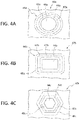
- FIGs 4A, 4B, and 4C show non-limiting geometric options for the shapes of the geometric perimeters of the reinforcing regions and the number of geometric perimeters induced into the composite component within a reinforcing region.
- FIG. 4A shows an overhead plan view of a composite component 40a that can be, for example a spar web, or other composite component having an access opening that is circular in shape.
- Composite component 40a includes a composite component planar section 42a with composite component planar section edge 48a forming a circular perimeter that surround a circular composite component access opening 44a.
- FIG. 4A shows, in further detail, reinforcing region 46a of the composite component 40a.
- reinforcing region 46a includes a geometric zone 47a that deviates from, or is "out-of-plane" with composite component planar section 42a.
- FIG. 4B shows an overhead plan view of a composite component 40b that can be, for example a spar web, or other composite component having an access opening that is rectangular in shape.
- Composite component 40b includes a composite component planar section 42b with composite component planar section edge 48b forming a rectangular perimeter that surround a rectangular composite component access opening 44a.
- FIG. 4B shows, in further detail, reinforcing region 46b of the composite component 40b. As shown in FIG. 4B , reinforcing region 46b includes a geometric zone 47b that deviates from, or is "out-of-plane" with composite component planar section 42b.
- FIG. 4C shows an overhead plan view of a composite component 40c that can be, for example a spar web, or other composite component having an access opening that is hexagonal in shape.
- Composite component 40c includes a composite component planar section 42c with composite component planar section edge 48c forming a hexagonal perimeter that surround a circular composite component access opening 44c.
- FIG. 4C shows, in further detail, reinforcing region 46c of the composite component 40c. As shown in FIG. 4C , reinforcing region 46c includes a geometric zone 47c that deviates from, or is "out-of-plane" with composite component planar section 42c.
- FIG. 5A is a non-limiting illustration according to further present aspects.
- FIG. 5A shows an overhead plan view of a composite component 50 that can be, for example a spar web, or other composite component having an access opening 54 that is circular in shape.
- Composite component 50 includes composite component planar sections 52, 52b, and 52c.
- Composite component planar section edge 52a forms a rectangular perimeter that surrounds a composite component access opening 54 that appears rectangular in shape.
- FIG. 5A shows in further detail, reinforcing region 56 of the composite component 50. As shown in FIG.
- reinforcing region 56 includes first geometric zone 57a and second geometric zone 57b that deviate from, or are "out-of-plane” with, composite component planar sections that exist adjacent to the composite component access opening 54. Additional composite material planar sections 52b, 52c (located at increasing distances from the access opening 54) are shown oriented "outside of' the periphery of the first and second geometric zones 57a and 57b, respectively, of the reinforcing region 56.
- FIG. 5B is an enlarged cross-sectional side view of the composite component shown in FIG. 5A taken along line 5B-5B.
- the centrally located composite component access opening 54 is surrounded by the composite component planar section edge 52a that adjoins composite component planar section 52.
- the first geometric zone 57a is shown as a raised region (and is shown in FIG. 5A as a rectangular "ring").
- the first geometric zone adjoins a composite component planar section 52b that, in turn adjoins the second geometric zone 57b again shown as a raised region (and that is shown in FIG.
- composite components used in the formation of the exterior of a larger structure can further require attention paid to aspects that can include the impact of a composite component in maintaining a desired outer mold line (OML).
- OML outer mold line
- present aspects facilitate the establishment and maintenance of predetermined design specifications to achieve and maintain a predetermined OML
- FIGs. 6A and 6B are non-limiting illustrations of an exterior composite component for an aircraft illustrating the establishment and maintenance of an OML.
- a composite component is the form of an exterior composite skin component 60 having a composite skin component exterior 60a, a composite skin component interior 60b, and a composite skin component planar section 62.
- the exterior composite skin component 60 further includes a composite skin component planar section edge 62a, and shown in FIG. 6A forming a perimeter encircling an exterior composite skin component access opening 64, with the exterior composite skin component access opening 64 extending through the exterior composite skin component 60.
- FIG. 6A is the form of an exterior composite skin component 60 having a composite skin component exterior 60a, a composite skin component interior 60b, and a composite skin component planar section 62.
- the exterior composite skin component 60 further includes a composite skin component planar section edge 62a, and shown in FIG. 6A forming a perimeter encircling an exterior composite skin component access opening 64, with the exterior composite skin component access opening 64 extending through the
- 6A further shows an induced reinforcing region 66 that includes at least one geometric out-of-plane perimeter 68 surrounding the exterior composite skin component access opening 64 generally (at a predetermined distance from the access opening 64), and surrounding the exterior composite skin component planar section 62 specifically.
- FIG. 6B is an illustration showing an enlarged cross-sectional side view of the composite component in the form of the exterior composite skin component 60 shown in FIG. 6A taken across line 6A-6A shown in FIG. 6A.
- FIG. 6B shows the exterior composite skin component planar section 62 with an exterior composite skin component planar section edge 62a forming a perimeter encircling an access opening 64, with the access opening 64 extending through the exterior composite skin component 60.
- FIG. 6B further shows an induced reinforcing region 66 that includes at least one geometric out-of-plane perimeter 68 surrounding the access opening 64 generally (at a predetermined distance from the access opening and) and surrounding the exterior composite skin component planar section 62 specifically. As shown in FIG.
- a cover in the form of an exterior access door 69 that includes an exterior access door exterior 69a and an exterior access door interior 69b is shown in place adjacent to the access opening 64.
- Exterior access door 69 can seal the access opening 64 and establish an intimate "fit" and orientation in combination with the exterior composite skin component 60 such that the exterior access door exterior 69a in combination with the skin component exterior 60a establishes and maintains a predetermined outer mold line (OML) at least for the purpose of maintaining a predetermined aerodynamic surface.
- OML outer mold line
- Exterior access door 69 may be mechanically attached with fasteners; likewise, access door may be bonded (e.g., adhesively bonded, etc.) to the mating surface of the present aspect, exterior composite skin component planar section 62 and induced reinforcing region induced reinforcing region 66, using adhesive or similar moldable material.
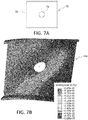
- FIG. 7A shows, as a "control", a composite component test sample 70 (in the form of a C-channel spar) having in-plane surfaces 72 and an access opening 74 and without the presence of a reinforcement region according to present aspects.
- Engineering developed buckling load analysis was conducted and validated by Finite Element Method (FEM) analysis to introduce in-plane shear strain by applying tension load in opposite corners of analyzed components. A readout of the buckling forces across the area of the composite component test sample 70 was generated.
- FEM Finite Element Method
- FIG. 7B shows a readout 70a of the buckling load analysis conducted for composite component test sample 70 showing the magnitude of buckling forces in the FIG. 7B key (in the inset) under a cantilever beam bending condition.
- FIG. 7B shows a composite component 80 in the form of a C-channel spar, having in-plane surfaces 82, an access opening 84 and an induced reinforcement region 86 with reinforcement region 86, according to present aspects.
- FEM Finite Element Method
- FIG. 7D is a readout of the buckling force analysis conducted for composite component 80 that included the reinforcing regions according to present aspects, with the predicted buckling load readout showing a buckling load force magnitude of 45 kips, (shown in the FIG. 7D key), representing a 45% improvement in buckling load resistance as compared to the buckling load resistance of composite component test sample 70 (the control sample).
- FIG. 7B demonstrates typical web buckling shape resulting in composite component test sample 70 that does not include the reinforcement regions.
- FIG. 7D demonstrates a buckling shape that reversed. That is, the induced reinforcement regions force the C-channel spar section to buckle "against" the natural buckling tendency of the C-channel section, resulting in a buckling load improvement of about 45%, and further resulting in an increased capability of a post-buckled structure.
- the epicenter of the highest buckling load regions 88 did not occur at the access opening perimeter. Instead, as shown in readout 80a, the epicenter of the highest strain/buckling force was relocated or otherwise dispersed away from the perimeter of the access opening to a location on composite component test sample 80, with a recorded buckling load value of 45 kips.
- Baseline peak strain values were obtained from a Finite Element Analysis (FEA) on a composite component that does not include the presently disclosed induced reinforcement regions, and then comparing the peak strain values for composite components having induced reinforcement regions incorporated using the same FEA analysis approach, according to present aspects, having induced reinforcement regions incorporated.
- FEA Finite Element Analysis
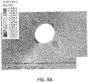
- FIG. 8A shows a readout of the peak strain testing conducted for the composite component test sample 70 (shown in FIG 7A ; the control composite component without the reinforcement regions) showing the magnitude of peak strain in the FIG. 8A key (in the inset).
- the highest peak strain values at the access opening perimeter indicate a recorded peak strain level, beyond which the composite component is said to "fail”.
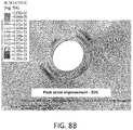
- FIG. 8B is a representation of a readout illustrating a reduced strain incurred over the same load for a composite component 80 having the induced reinforcement regions according to present aspect as compared to the composite component test sample 70 as shown in FIG. 8A .
- the same load was applied to the composite component test sample 70 (results shown in FIG. 8A ) and the composite component 80 including reinforcement regions (results shown in FIG. 8B ).
- the strain magnitude of the composite component 80 that includes the induced reinforcement regions showed strain reduction in a pre-buckled state of approximately 25% as compared to the analyzed composite component test sample 70 (shown in FIG. 8A ) that did not include the induced reinforcement regions.
- FIG. 8B illustrates a readout of the peak strain analysis conducted for composite component 80 comprising the reinforcing regions according to present aspects, with the recorded peak strain values shown in the FIG. 8B key.
- the epicenter of the highest peak strain regions did not occur at the access opening perimeter. Instead, as shown in the readout shown in FIG. 8B , the epicenter of the highest peak strain force for sample 80 (shown in FIG. 7C ; the sample with the reinforcing regions, and according to present aspects) was lower by at least about 25% than the peak strain value recorded for the composite component test sample 70.
- FIG. 7C the epicenter of the highest peak strain force for sample 80
- FIG. 7C the sample with the reinforcing regions, and according to present aspects
- the peak strain was relocated, or otherwise dispersed away, from the perimeter of the access opening and was decentralized, or broken into multiple areas of peak strain (rather than the concentration of peak strain that is shown in FIG. 8A for composite component test sample 70).
- peak strain values obtained as shown in the key in FIG. 8B , the peak strain observed in the composite component incorporating the reinforcement region, according to present aspects, was approximately 25% lower than the peak strain values obtained for the composite component test sample 70 (without the reinforcing regions), and shown in the key attending FIG. 8A .
- the decentralization or "breaking up" of the peak strains observed in the readout shown in FIG. 8B and the reduction in peak strain observed in the composite component 80 (incorporating the reinforcing region) also improved post-buckled structure capability.
- FIGs. 9 and 10 are flowcharts outlining methods according to present aspects.
- a method 100 for manufacturing reinforced composite components according to present aspects is outlined, with the method 100 including laying up 102 prepreg plies of composite material to form a composite laminate, with the composite material having access openings, or with the composite material prepared for machining to create an access opening.
- the method 100 further includes imparting 104 out-of-plane reinforcing regions proximate to the composite laminate access opening regions during layup, flowed by curing 106 the composite laminate to form a composite component with induced reinforcement regions proximate to the access opening.
- FIG. 10 illustrates a method 200 for manufacturing and installing the presently disclosed composite components according to present aspect with the method 200 including manufacturing 202 a composite component having an access opening, and with the composite component having induced out-of-plane reinforcing regions locate proximate to the access opening.
- Method 200 optionally includes installing 204 the composite component having induced out-of-plane reinforcing regions locate proximate to the access opening into at least one of: a larger structure, an assembly, and a sub-assembly.
- the installing 204 step can optionally include installing the composite component having induced out-of-plane reinforcing regions by at least one of: mechanical fasteners and adhesive bonding.
- FIGs 9 and 10 can implement the reinforced composite components having the reinforcing regions located proximate to access openings in the composite component as disclosed herein, and according to present aspects, and as shown in any of FIGs. 1 , 1A , 1B, 2, 3 , 4A, 4B, 4C 5A, 5B , 6A, 6B and 7C .
- the out-of-plane geometric zones induced in the induced reinforcement regions of composite components can be continuous or can be discontinuous; with the geometric pattern (e.g., circle, square, rectangle, hexagon, etc.) "broken", interrupted, or otherwise perceived to be discontinuous while also imparting advantageous out-of-plane stiffening increases, and other advantageous composite material property and material performance improvements (e.g., when the composite component is placed under strain loads, etc.).
- geometric pattern e.g., circle, square, rectangle, hexagon, etc.
- present aspects include geometric zones in the reinforcement regions that can be discontinuous with substantially all sections of the geometric zones being out-of-plane relative to the planar composite component
- substantially all sections of the geometric zones being out-of-plane means that up to 10% of the geometric zone can have be planar, or otherwise not be out-of-plane.
- Ductile materials including certain metals can be subjected to various "post-fabrication" reinforcing and strengthening regimens including, for example, welding, brazing, stamping, etc.
- post-fabrication properties of cured composite materials including thermoplastic and thermoset polymeric composite materials that exhibit high strength and low weight do not lend themselves to the post-processing reinforcing techniques used in materials including heavier metallic materials. Accordingly, as mentioned above, present aspects are directed to introducing reinforcement regions to composite materials having access openings during the composite prepreg layup stages composite material manufacturing.
Landscapes
- Engineering & Computer Science (AREA)
- Mechanical Engineering (AREA)
- Chemical & Material Sciences (AREA)
- Composite Materials (AREA)
- Aviation & Aerospace Engineering (AREA)
- Architecture (AREA)
- Civil Engineering (AREA)
- Structural Engineering (AREA)
- Moulding By Coating Moulds (AREA)
Abstract
Description
- The present disclosure relates generally to the field of structural reinforcement. More specifically the present disclosure relates to the field of reinforcing composite component structures by reducing peak strain at locations of large composite component structures.
- Isolated locations of components on large structure can incur peak strain variations during use. At such locations, that can include joints and apertures, prolonged exposure to certain peak strain levels can lead to material fatigue. In the case of composite materials made from layers of layed-up materials (e.g., cured epoxy resin impregnated layers, or "prepregs", etc.), excessive peak strain exhibited at certain locations, and over, for example, sustained and predetermined durations can cause deformation of a structure, delamination of a structural component, or other conditions that evidence undesirable material fatigue. Such material fatigue can adversely impact the expected performance of such materials, and further lead to premature rework of structures, structural components, assemblies and sub-assemblies that comprise such structures and structural components.
- Reinforcing composite component areas that endure enhanced material strain forces have required a localized, or "regional" build-up of additional material that significantly increases manufacturing complexity and significantly increases overall weight of the composite component due to the total material increase in creating the localized build-up of material to reinforce composite components against peak strain, and otherwise impacts overall structural design of a composite component.
- According to present aspects, a method is disclosed for reinforcing a composite component by imparting (referred to equivalently herein as "inducing") reinforcing features to the composite component, with the method including laying up a plurality of prepreg plies on a layup tool to form a composite component laminate, with the layup tool including a planar region (referred to equivalently herein as "planar section", "in-plane region", and "in-plane section") on the tool and at least one out-of-plane feature on the tool. The method further includes imparting a non-planar region (referred to equivalently herein as "non-planar section", "out-of-plane region", and "out-of-plane section") to the composite component laminate and curing the composite laminate material to form a cured composite component, with the cured composite component including a planar region adjacent to an access opening, with the access opening extending through the composite component, and with the planar region comprising a first thickness. The cured composite laminate further includes an induced out-of-plane reinforcing region, said induced out-of-plane reinforcement region (referred to equivalently herein as an "induced non-planar reinforcement region") located a predetermined distance from the access opening, and with the induced reinforcement region including an out-of-plane geometric perimeter (referred to equivalently herein as a "non-planar geometric perimeter"), said out-of-plane geometric perimeter surrounding the access opening, and with the out-of-plane geometric perimeter comprising a second thickness, and wherein the first thickness and the second thickness are substantially equivalent.
- In another aspect, the number of prepreg plies applied to the planar region on the tool is equivalent to the number of prepreg plies applied to the out-of-plane feature on the tool.
- In a further aspect, the composite material is a thermoplastic polymeric material.
- In another aspect, the composite material is a thermoset polymeric material.
- According to present aspects, a method is disclosed for reinforcing a composite component by imparting reinforcing features to the composite component, with the method including manufacturing a composite component comprising an access opening, with the composite component including a planar region proximate to the access opening and an induced out-of-plane reinforcing region, with the induced out-of-plane reinforcing region located a predetermined distance from the access opening, and with the induced reinforcement region comprising an out-of-plane geometric perimeter, with the out-of-plane geometric perimeter surrounding the access opening at a predetermined distance from the access opening.
- In another aspect, the induced out-of-plane reinforcing region alters the strain pattern to a predetermined degree through the composite component.
- In a further aspect, the composite material comprises at least one of: a thermoplastic polymeric material and a thermoset polymeric material.
- Further aspects are directed to a component with the component including a composite component, and with the composite component including a planar region adjacent to and substantially surrounding an access opening, with the access opening extending through the composite component, and with the planar region comprising a first thickness. The component further includes an induced reinforcing region, said induced reinforcement region located a predetermined distance from the access opening, and said induced reinforcement region comprising a geometric perimeter, with the geometric perimeter surrounding the access opening, with the geometric perimeter comprising a second thickness, and wherein the first thickness and the second thickness are substantially equivalent.
- In another aspect, the induced reinforcing region comprises a reinforcing segment that is out-of-plane as compared to the planar region.
- In another aspect, the induced reinforcing region increases the buckling load of the component by about 45% as compared to a component without the induced reinforcing region.
- In a further aspect, the induced reinforcing region increases the out-of-plane stiffness of the component.
- In another aspect, the induced reinforcing region counteracts buckling forces sustained by the component during use of the component.
- In another aspect, the induced reinforcing region increases the damage arrest capability of the component during use of the component.
- In another aspect, the induced reinforcing region alters an in-plane strain pattern to a predetermined degree across the component.
- In a further aspect, the induced reinforcing region decreases peak strain in the composite component in the reinforcement region by about 25% as compared to a component without the induced reinforcing component.
- In another aspect, the component is dimensioned to mate with an external cover, and wherein said cover in combination with the component preserves an outer mold line.
- In another aspect, the composite material comprises a predetermined number of cured prepregs.
- In another aspect, the substantially planar region and the induced reinforcing region comprise an equivalent number of cured prepregs.
- A further aspect is directed to a structure including a composite component, with the composite component including a planar region adjacent to and substantially surrounding an access opening, with the access opening extending through the composite component, and with the planar region comprising a first thickness. The component further includes an induced reinforcing region, said induced reinforcement region located a predetermined distance from the access opening, and said induced reinforcement region comprising a geometric perimeter, with the geometric perimeter surrounding the access opening, with the geometric perimeter comprising a second thickness, and wherein the first thickness and the second thickness are substantially equivalent.
- In another aspect, the structure includes at least one of a manned aircraft, an unmanned aircraft, a manned spacecraft, an unmanned spacecraft, a manned rotorcraft, an unmanned rotorcraft, a manned terrestrial vehicle, an unmanned terrestrial vehicle, a surface water borne vehicle, a subsurface water borne vehicle, a hovercraft, and combinations thereof.
- The features, functions and advantages that have been discussed can be achieved independently in various aspects or may be combined in other aspects, further details of which can be seen with reference to the following description and the drawings.
- Having thus described variations of the disclosure in general terms, reference will now be made to the accompanying drawings, which are not necessarily drawn to scale, and wherein:
-
FIG. 1 is an illustration of a vehicle in the form of an aircraft, according to present aspects; -
FIG. 1A is an illustration of an airfoil that includes an access opening in a C-channel spar component that can be subject to high shear loads that can induce peak strains at the edge of the access hole, according to present aspects; -
FIG. 1B is an enlarged view of illustrating a section of a C-channel spar showing an access opening, according to present aspects; -
FIG. 2 is an illustration of a cross-sectional view of the component shown inFIG. 1B , according to present aspects; -
FIG. 3 is an illustration of an enlarged cross-sectional view of the component shown inFIG. 2 , according to present aspects; -
FIG. 4A is an illustration of a plan view of a component comprising an induced reinforcement having a predetermined geometry, according to present aspects; -
FIG. 4B is an illustration of a plan view of a component comprising an induced reinforcement having a predetermined geometry, according to present aspects; -
FIG. 4C is an illustration of a plan view of a component comprising an induced reinforcement having a predetermined geometry, according to present aspects; -
FIG. 5A is an illustration of a plan view of a component comprising present aspects; -
FIG. 5B is an illustration of a cross-sectional view the components shown inFIG. 5A , taken along "line 5B", according to present aspects; -
FIG. 6A is an illustration of a plan view of a component comprising present aspects; -
FIG. 6B is an illustration of a cross-sectional view the components shown inFIG. 6A , taken along "line 6B", according to present aspects; -
FIG. 7A is an illustration of a plan view of a composite component control test sample (e.g., in the form of a conventional C-channel spar) that does not have the induced reinforcement (and in contrast to present aspects); -
FIG. 7B is a representation of a readout illustrating out-of-plane deflection of web incurred by the composite component control test sample (e.g., in the form of a conventional C-channel spar) under cantilever beam bending condition as shown inFIG. 7A (and in contrast to present aspects); -
FIG. 7C is an illustration of a plan view of a component according to present aspects; -
FIG. 7D is a representation of a readout illustrating improvement to buckling load incurred by the component as shown inFIG. 7C , according to present aspects; -
FIG. 8A is a representation of a readout illustrating a strain incurred by a composite component control test sample (e.g., in the form of a conventional C-channel spar) in a pre-buckled state (that does not include the induced reinforcement present according to present aspects); -
FIG. 8B is a representation of a readout illustrating a reduced strain incurred by the component as compared to the component shown inFIG. 8A at a same applied load in a pre-buckled state where strain magnitude is reduced by approximately 25% due to the present aspects; -
FIG. 9 is a flowchart outlining a method according to a present aspect; and -
FIG. 10 is a flowchart outlining a method according to a present aspect. - Structural composite components that have an area on the component that is coincident with locations that can exhibit high peak strain during use can impact the structural performance of such components, as well as lead to the need for replacing, reworking, increasing the frequency of inspection regimens, etc., of the such structural composite components. According to present aspects, composite components (e.g., components made from composite materials) are structurally reinforced to withstand high peak strain levels by, among other factors, interrupting the strain load that would otherwise normally occur, without adding additional weight to the component, or otherwise providing augmented material layering at a reinforcement region.
-
FIG. 1 is a non-limiting illustration of a vehicle in the form of an aircraft incorporating composite components according to present aspects, As shown inFIG. 1 , vehicle/aircraft 10 includes afuselage 11,wings 12 and a tail section including avertical stabilizer 14 andhorizontal stabilizer 16. -
FIG. 1A is an enlarged and a partially exposed view of ahorizontal stabilizer 16 acting as an airfoil for the illustrated aircraft.Horizontal stabilizer 16 includes internally located C-channel spars 17 with arear spar 17a located longitudinally along the rear edge of thehorizontal stabilizer 16.FIG. 1B is an enlarged view of therear spar 17a showing a composite component (e.g., made from a composite material) in the form of a C-channel spar web 20. As shown inFIG. 1B , the C-channel spar web 20 includes a spar webplanar section 22 with spar webplanar section edge 22a forming a perimeter encircling a spar web access opening 24, with the spar web access opening 24 extending through the thickness (t', as shown inFIG. 3 ) of the sparweb access opening 24.FIG. 1B further shows an induced reinforcingregion 26 that includes at least onegeometric zone 28 surrounding theaccess opening 24. - The composite components manufactured with the reinforcing features and reinforcing regions according to present aspects can be composite components that are manufactured to include an access opening, with the composite component made from thermoplastic polymer composite material and thermoset polymer composite materials. Further, according to present aspects, composite components of many types can be reinforced using presently disclosed methods and by imparting or inducing the presently disclosed reinforcing regions. Composite components having integrated access openings machined into, or otherwise formed into their structure find utility integrating present aspects, as such composite components, during their component lifetime in use, can bear unique strain loads when they are incorporated into larger structures, sub-assemblies, assemblies, etc., as load bearing components are joined to or pass through the access openings of the presently contemplated composite components having access openings.
-
FIG. 2 is an illustration showing an enlarged cross-sectional side view of a section of thespar web 20 shown inFIG. 1B and taken across line 2-2 as shown inFIG. 1B . As shown inFIG. 2 , the spar webplanar section 22 includes spar webplanar section edge 22a that forms a perimeter that encircles a sparweb access opening 24.FIG. 2 further shows induced reinforcingregion 26 of the spar web. -
FIG. 3 is an illustration showing a further enlarged cross-sectional side view of thespar web 20 shown inFIGs. 1B and 2 and taken across line 2-2 as shown inFIG. 1B . As shown inFIG. 3 , the spar webplanar section 22 includes spar webplanar section edge 22a that forms a perimeter that encircles a sparweb access opening 24.FIG. 3 shows, in further detail, reinforcingregion 26 of the spar web. As shown inFIG. 3 , reinforcingregion 26 includes ageometric zone 28 that deviates from, or is "out-of-plane" with, spar webplanar section 22.FIG. 3 further shows that reinforcingregion 26 includes firstangle deviation point 26a in thegeometric zone 28 where a first angular deviation occurs from the planar (180 degree) orientation of the spar webplanar section 22. As also shown inFIG. 3 , reinforcingregion 26 further show a secondangle deviation point 26b where a second angular deviation occurs; the second angular deviation shown as deviating from the plane of thegeometric zone 28 in the reinforcing region 26 (that is out-of-plane with the spar web planar section 22). - As shown in
FIG. 3 , the portion of the spar web shown inFIG 3 at secondangle deviation point 26b can "correct" the first angular deviation from a planar orientation of the spar web planar section. For example, combining the angles at first and second angle deviation points, 26a, 26b respectively, the angular deviation of thegeometric zone 28 in the reinforcingregion 26 from the spar webplanar section 22 at firstangle deviation point 26a, is "countered" or "returned to an initial planar orientation, such that the combined value of angles at first and second angle deviation points 26a and 26b totals about 180 degrees. - Though not shown, present aspects further contemplate second angle deviation point 16b representing an angle of deviation that, when combined with the angular deviation represented at
angle deviation point 26a does not equal 180 degrees, and therefore does not return the plane angle outside of the reinforcing region precisely to a plane angle equal to the plane of the spar webplanar section 22, as dictated by various component design configurations. - Though not shown, present aspects further contemplate additional angle deviation points (more than the two
angle deviation points FIG. 3 ) being introduced into a composite component, if desired. That is, the reinforcing region that includes the geometric zones, and that is located proximate to and at a predetermined distance from an access opening in a composite component can include one or more geometric zones, with one or more geometric perimeters present within a given geometric zone (e.g., a number to include, for example, 1, 2, 3, 4, 5, 6, 7, 8 or more, etc., geometric perimeters within a given geometric zone, etc.) with each geometric zone including the same or different geometric shapes, (with the term "geometric shapes" referred to equivalently herein as "geometries"), including, for example, regular geometries including circles, squares, rectangles, hexagons, trapezoids, rhombuses, ellipses, etc., and/or irregular geometries and/or irregular patterns. - In addition, the height of the geometric zone(s) in the reinforcing region (e.g., the distance from a planar surface of the composite component occurring at the "base" of a geometric zone surface to the top surface of the geometric zone of the reinforcing region) and the angle of deviation from the planar surface, and the slope, and the slope changes in the geometric zone of the reinforcement region can be tailored, for example, to yield an improved predetermined effect in the resulting composite components in terms of buckling resistance, damage resistance, strain pattern dissipation, strain pattern interruption, interruption of load path, increase in out-of-plane stiffness, etc. Again, the improved out-of-plane stiffness and other properties imparted to the composite components through the benefit of the presently disclosed aspects are achieved without adding weight to the composite component, as no additional material is deposited at the reinforcing regions prior to, during or after the manufacture (e.g., the laying up and curing) of the composite components.
- The out-of-plane features and regions that are introduced into the layed up composite laminate by the layup tool are induced areas of "relief' as compared to the planar regions in the layed up composite laminate. Such "relief' features that deviate from the plane of the majority of the planar surface can also be referred to as joggles. The induced joggles have a predetermined geometry and dimension with predetermined step height and ramp. According to present aspects, the dimension and geometry of the induced relief areas, or joggles, can be tailored to achieve a desired reinforcing result in terms of advantageous buckling load increases, strain pattern interruption, etc., without adding addition prepreg segments or buildup at the reinforcing regions of relief (joggles). As a result the weight of the cured composite component made from the cured composite laminate does not increase, even though the composite component has been significantly reinforced and strengthened in the region of the access opening and throughout the composite component, as the strain patterns are interrupted and strain loads and buckling loads are significantly increased.
- The induced out-of-plane reinforcing joggles can include directional or angular deviation from the general plane of the composite component by about +/- 45 degrees. In addition, smaller angles ranging from about +/- 25 degrees to about +/- 75 degrees can accomplish predetermined amounts of reinforcing improvement, especially if a plurality of joggles are induced as a continuous or discontinuous perimeter or series of "ringed perimeters" induced proximate to the access opening and substantially surrounding the access opening.
- According to present aspects, the step height of a joggle (e.g., the height or distance of a joggle away from the planar surface of a component) can impact the reinforcing impact observed by the composite component in the area of the access opening and across the area of the composite component. According to present aspects, step heights of the out-of-plane reinforcement features, or joggles, can be tailored to deliver a predetermined increase in the composite component strength properties in terms of buckling load increases and strain load/pattern interruption. Present aspects contemplate a step height of joggle ranging from about 0.5 times to about 1.5 times the composite component laminate thickness.
- Regarding the various geometries of the reinforcing region presently contemplated, according to present aspects,
FIGs 4A, 4B, and 4C show non-limiting geometric options for the shapes of the geometric perimeters of the reinforcing regions and the number of geometric perimeters induced into the composite component within a reinforcing region. For example,FIG. 4A shows an overhead plan view of acomposite component 40a that can be, for example a spar web, or other composite component having an access opening that is circular in shape.Composite component 40a includes a composite componentplanar section 42a with composite componentplanar section edge 48a forming a circular perimeter that surround a circular composite component access opening 44a.FIG. 4A shows, in further detail, reinforcingregion 46a of thecomposite component 40a. As shown inFIG. 4A , reinforcingregion 46a includes ageometric zone 47a that deviates from, or is "out-of-plane" with composite componentplanar section 42a. - In another example of a contemplated geometric perimeter shape,
FIG. 4B shows an overhead plan view of acomposite component 40b that can be, for example a spar web, or other composite component having an access opening that is rectangular in shape.Composite component 40b includes a composite componentplanar section 42b with composite componentplanar section edge 48b forming a rectangular perimeter that surround a rectangular composite component access opening 44a.FIG. 4B shows, in further detail, reinforcingregion 46b of thecomposite component 40b. As shown inFIG. 4B , reinforcingregion 46b includes ageometric zone 47b that deviates from, or is "out-of-plane" with composite componentplanar section 42b. - In another example of a contemplated geometric perimeter shape,
FIG. 4C shows an overhead plan view of acomposite component 40c that can be, for example a spar web, or other composite component having an access opening that is hexagonal in shape.Composite component 40c includes a composite componentplanar section 42c with composite componentplanar section edge 48c forming a hexagonal perimeter that surround a circular composite component access opening 44c.FIG. 4C shows, in further detail, reinforcingregion 46c of thecomposite component 40c. As shown inFIG. 4C , reinforcingregion 46c includes ageometric zone 47c that deviates from, or is "out-of-plane" with composite componentplanar section 42c. - As mentioned above, according to present aspects, a reinforcing region can include multiple geometric perimeters.
FIG. 5A is a non-limiting illustration according to further present aspects.FIG. 5A shows an overhead plan view of acomposite component 50 that can be, for example a spar web, or other composite component having an access opening 54 that is circular in shape.Composite component 50 includes composite componentplanar sections planar section edge 52a forms a rectangular perimeter that surrounds a composite component access opening 54 that appears rectangular in shape.FIG. 5A , shows in further detail, reinforcingregion 56 of thecomposite component 50. As shown inFIG. 5A , reinforcingregion 56 includes firstgeometric zone 57a and secondgeometric zone 57b that deviate from, or are "out-of-plane" with, composite component planar sections that exist adjacent to the composite component access opening 54. Additional composite materialplanar sections geometric zones region 56. -
FIG. 5B is an enlarged cross-sectional side view of the composite component shown inFIG. 5A taken alongline 5B-5B. As shown inFIG. 5B , the centrally located composite component access opening 54 is surrounded by the composite componentplanar section edge 52a that adjoins composite componentplanar section 52. Moving outwardly in both directions (from the composite component planar section 52) the firstgeometric zone 57a is shown as a raised region (and is shown inFIG. 5A as a rectangular "ring"). Moving outwardly, the first geometric zone adjoins a composite componentplanar section 52b that, in turn adjoins the secondgeometric zone 57b again shown as a raised region (and that is shown inFIG. 5A as a larger rectangular "ring"), which, in turn adjoins an outermost composite componentplanar section 52c that also can represent the outermost region (equivalently referred to herein as the "outer periphery", or "outer perimeter") of the reinforcingregion 56. - According to present aspects, composite components used in the formation of the exterior of a larger structure can further require attention paid to aspects that can include the impact of a composite component in maintaining a desired outer mold line (OML). For example, in an aircraft, doors, covers, etc. fit into or "mate" flush with access openings to maintain a desired OML, according to predetermined aircraft design specifications, whereas the door, cover, etc., may be mechanically attached or permanently bonded with adhesive to the mating surface of the present aspect. Present aspects facilitate the establishment and maintenance of predetermined design specifications to achieve and maintain a predetermined OML
-
FIGs. 6A and 6B are non-limiting illustrations of an exterior composite component for an aircraft illustrating the establishment and maintenance of an OML. As shown inFIG. 6A , a composite component is the form of an exteriorcomposite skin component 60 having a compositeskin component exterior 60a, a composite skin component interior 60b, and a composite skin componentplanar section 62. The exteriorcomposite skin component 60 further includes a composite skin componentplanar section edge 62a, and shown inFIG. 6A forming a perimeter encircling an exterior composite skin component access opening 64, with the exterior composite skin component access opening 64 extending through the exteriorcomposite skin component 60.FIG. 6A further shows an induced reinforcingregion 66 that includes at least one geometric out-of-plane perimeter 68 surrounding the exterior composite skin component access opening 64 generally (at a predetermined distance from the access opening 64), and surrounding the exterior composite skin componentplanar section 62 specifically. -
FIG. 6B is an illustration showing an enlarged cross-sectional side view of the composite component in the form of the exteriorcomposite skin component 60 shown inFIG. 6A taken across line 6A-6A shown inFIG. 6A. FIG. 6B shows the exterior composite skin componentplanar section 62 with an exterior composite skin componentplanar section edge 62a forming a perimeter encircling anaccess opening 64, with the access opening 64 extending through the exteriorcomposite skin component 60.FIG. 6B further shows an induced reinforcingregion 66 that includes at least one geometric out-of-plane perimeter 68 surrounding the access opening 64 generally (at a predetermined distance from the access opening and) and surrounding the exterior composite skin componentplanar section 62 specifically. As shown inFIG. 6B , a cover in the form of anexterior access door 69 that includes an exterioraccess door exterior 69a and an exterior access door interior 69b is shown in place adjacent to theaccess opening 64.Exterior access door 69, as shown, can seal the access opening 64 and establish an intimate "fit" and orientation in combination with the exteriorcomposite skin component 60 such that the exterioraccess door exterior 69a in combination with theskin component exterior 60a establishes and maintains a predetermined outer mold line (OML) at least for the purpose of maintaining a predetermined aerodynamic surface.Exterior access door 69, as shown, may be mechanically attached with fasteners; likewise, access door may be bonded (e.g., adhesively bonded, etc.) to the mating surface of the present aspect, exterior composite skin componentplanar section 62 and induced reinforcing region induced reinforcingregion 66, using adhesive or similar moldable material. - Engineering developed shear testing was conducted and validated by Finite Element Method (FEM) analysis to introduce in-plane shear strain by applying tension load in opposite corners of tested components. Comparative testing was conducted to determine the impact of the induced reinforcing regions manufactured into composite components. Baseline buckling load values were obtained by testing a composite component that does not include the presently disclosed induced reinforcement regions, and then comparing the buckling load values obtained for composite components, according to present aspects, having induced reinforcement regions incorporated. The engineering developed testing was conducted on carbon fiber reinforced epoxy thermoset laminate composite materials.
-
FIG. 7A shows, as a "control", a composite component test sample 70 (in the form of a C-channel spar) having in-plane surfaces 72 and anaccess opening 74 and without the presence of a reinforcement region according to present aspects. Engineering developed buckling load analysis was conducted and validated by Finite Element Method (FEM) analysis to introduce in-plane shear strain by applying tension load in opposite corners of analyzed components. A readout of the buckling forces across the area of the compositecomponent test sample 70 was generated. -
FIG. 7B shows areadout 70a of the buckling load analysis conducted for compositecomponent test sample 70 showing the magnitude of buckling forces in theFIG. 7B key (in the inset) under a cantilever beam bending condition. As shown inFIG. 7B the highest buckling load regions 78 appear at the access opening perimeter indicating a resistance level for buckling (an out-of-plane stiffness value), beyond which the composite component is said to "fail" at a recorded bucking load value of 31 kips (1 kip, or kilopound = 4448.2216 N = 4.4482216 kN). - In contrast to the results obtained and presented as shown in
FIG. 7B (e.g., for a composite component control test sample e.g., in the form of a conventional C-channel spar), engineering developed buckling load analysis was conducted and validated by Finite Element Method (FEM) analysis to introduce in-plane shear strain by applying tension load in opposite corners of tested components that included the induced reinforcement regions proximate to the access opening, and according to present aspects.FIG. 7C shows acomposite component 80 in the form of a C-channel spar, having in-plane surfaces 82, anaccess opening 84 and an inducedreinforcement region 86 withreinforcement region 86, according to present aspects. -
FIG. 7D is a readout of the buckling force analysis conducted forcomposite component 80 that included the reinforcing regions according to present aspects, with the predicted buckling load readout showing a buckling load force magnitude of 45 kips, (shown in theFIG. 7D key), representing a 45% improvement in buckling load resistance as compared to the buckling load resistance of composite component test sample 70 (the control sample). - The induced reinforcement regions according to present aspects, results in superior control of buckling behavior.
FIG. 7B demonstrates typical web buckling shape resulting in compositecomponent test sample 70 that does not include the reinforcement regions. By introducing the reinforcement regions in predetermined orientations, and according to present aspects,FIG. 7D demonstrates a buckling shape that reversed. That is, the induced reinforcement regions force the C-channel spar section to buckle "against" the natural buckling tendency of the C-channel section, resulting in a buckling load improvement of about 45%, and further resulting in an increased capability of a post-buckled structure. - As shown in
FIG. 7D the epicenter of the highest buckling load regions 88 did not occur at the access opening perimeter. Instead, as shown inreadout 80a, the epicenter of the highest strain/buckling force was relocated or otherwise dispersed away from the perimeter of the access opening to a location on compositecomponent test sample 80, with a recorded buckling load value of 45 kips. In other words, analysis demonstrated that thecomposite component sample 80 that incorporated the induced reinforcement region proximate to the access opening, and according to present aspects, realized a 45% improvement in buckling load, as well as an improved realized change in overall buckling shape (as compared to thesample 70 that did not incorporate the induced reinforcement region proximate to the access opening). - Baseline peak strain values were obtained from a Finite Element Analysis (FEA) on a composite component that does not include the presently disclosed induced reinforcement regions, and then comparing the peak strain values for composite components having induced reinforcement regions incorporated using the same FEA analysis approach, according to present aspects, having induced reinforcement regions incorporated.
-
FIG. 8A shows a readout of the peak strain testing conducted for the composite component test sample 70 (shown inFIG 7A ; the control composite component without the reinforcement regions) showing the magnitude of peak strain in theFIG. 8A key (in the inset). As shown inFIG. 8A the highest peak strain values at the access opening perimeter indicate a recorded peak strain level, beyond which the composite component is said to "fail". -
FIG. 8B is a representation of a readout illustrating a reduced strain incurred over the same load for acomposite component 80 having the induced reinforcement regions according to present aspect as compared to the compositecomponent test sample 70 as shown inFIG. 8A . The same load was applied to the composite component test sample 70 (results shown inFIG. 8A ) and thecomposite component 80 including reinforcement regions (results shown inFIG. 8B ). The strain magnitude of thecomposite component 80 that includes the induced reinforcement regions showed strain reduction in a pre-buckled state of approximately 25% as compared to the analyzed composite component test sample 70 (shown inFIG. 8A ) that did not include the induced reinforcement regions. -
FIG. 8B illustrates a readout of the peak strain analysis conducted forcomposite component 80 comprising the reinforcing regions according to present aspects, with the recorded peak strain values shown in theFIG. 8B key. As shown inFIG. 8B the epicenter of the highest peak strain regions did not occur at the access opening perimeter. Instead, as shown in the readout shown inFIG. 8B , the epicenter of the highest peak strain force for sample 80 (shown inFIG. 7C ; the sample with the reinforcing regions, and according to present aspects) was lower by at least about 25% than the peak strain value recorded for the compositecomponent test sample 70. In addition, as shown inFIG. 8B , the peak strain was relocated, or otherwise dispersed away, from the perimeter of the access opening and was decentralized, or broken into multiple areas of peak strain (rather than the concentration of peak strain that is shown inFIG. 8A for composite component test sample 70). Regarding peak strain values obtained, as shown in the key inFIG. 8B , the peak strain observed in the composite component incorporating the reinforcement region, according to present aspects, was approximately 25% lower than the peak strain values obtained for the composite component test sample 70 (without the reinforcing regions), and shown in the key attendingFIG. 8A . The decentralization or "breaking up" of the peak strains observed in the readout shown inFIG. 8B and the reduction in peak strain observed in the composite component 80 (incorporating the reinforcing region) also improved post-buckled structure capability. -
FIGs. 9 and10 are flowcharts outlining methods according to present aspects. As shown inFIG. 9 , amethod 100 for manufacturing reinforced composite components according to present aspects is outlined, with themethod 100 including laying up 102 prepreg plies of composite material to form a composite laminate, with the composite material having access openings, or with the composite material prepared for machining to create an access opening. Themethod 100 further includes imparting 104 out-of-plane reinforcing regions proximate to the composite laminate access opening regions during layup, flowed by curing 106 the composite laminate to form a composite component with induced reinforcement regions proximate to the access opening. -
FIG. 10 illustrates amethod 200 for manufacturing and installing the presently disclosed composite components according to present aspect with themethod 200 including manufacturing 202 a composite component having an access opening, and with the composite component having induced out-of-plane reinforcing regions locate proximate to the access opening.Method 200 optionally includes installing 204 the composite component having induced out-of-plane reinforcing regions locate proximate to the access opening into at least one of: a larger structure, an assembly, and a sub-assembly. The installing 204 step can optionally include installing the composite component having induced out-of-plane reinforcing regions by at least one of: mechanical fasteners and adhesive bonding. The methods set forth above and the methods outlined inFIGs 9 and10 can implement the reinforced composite components having the reinforcing regions located proximate to access openings in the composite component as disclosed herein, and according to present aspects, and as shown in any ofFIGs. 1 ,1A ,1B, 2, 3 ,4A, 4B, 4C 5A, 5B ,6A, 6B and7C . - The out-of-plane geometric zones induced in the induced reinforcement regions of composite components can be continuous or can be discontinuous; with the geometric pattern (e.g., circle, square, rectangle, hexagon, etc.) "broken", interrupted, or otherwise perceived to be discontinuous while also imparting advantageous out-of-plane stiffening increases, and other advantageous composite material property and material performance improvements (e.g., when the composite component is placed under strain loads, etc.). That is, present aspects include geometric zones in the reinforcement regions that can be discontinuous with substantially all sections of the geometric zones being out-of-plane relative to the planar composite component According to the present disclosure, substantially all sections of the geometric zones being out-of-plane means that up to 10% of the geometric zone can have be planar, or otherwise not be out-of-plane.
- Ductile materials, including certain metals can be subjected to various "post-fabrication" reinforcing and strengthening regimens including, for example, welding, brazing, stamping, etc. In contrast to more ductile materials, the post-fabrication properties of cured composite materials, including thermoplastic and thermoset polymeric composite materials that exhibit high strength and low weight do not lend themselves to the post-processing reinforcing techniques used in materials including heavier metallic materials. Accordingly, as mentioned above, present aspects are directed to introducing reinforcement regions to composite materials having access openings during the composite prepreg layup stages composite material manufacturing.
- Further, while methods for reinforcing composite materials have included the addition of prepreg ply layers to form "built up" reinforcement regions, such methods have required the addition of composite material layers, pre- or post-cure, to composite materials and such reinforced composite materials have not been achievable without producing a composite material having a significant weight increase as compared to the non-reinforced composite material (due to the additional weight of reinforcement laminated regions).
- It was surprisingly found that forming out-of-plane reinforcing regions in layed-up laminates of composite material prepregs (prior to curing), and locating the out-of plane reinforcing regions proximate to where access openings will occur in a final cured composite component, significantly altered and significantly improved strain patterns in composite materials. The improved physical characteristics were achieved without adding weight, as not additional material was applied to or added to the reinforcing regions. Though bound by no singular theory, it is now believed that lighter composite components having superior buckling resistance near access openings can be obtained by implementing presently disclosed aspects and inducing reinforcing regions while possibly reducing the overall thicknesses of composite material laminate layups that was previously required. Such a potential reduction in composite component thickness without sacrificing strength in terms of, for example, out-of-plane stiffness and buckling resistance, can potentially lead to even lighter weight composite components having equivalent strength by inducing the reinforcement regions set forth and described herein.
- The description comprises the following clauses.
-
Clause 1. A component comprising a composite material, said composite material comprising a planar region adjacent to and substantially surrounding an access opening, said access opening extending through the composite material, said planar region comprising a first thickness; an induced reinforcing region, said induced reinforcement region located a predetermined distance from the access opening, and said induced reinforcement region comprising a geometric perimeter, said geometric perimeter surrounding the access opening, said geometric perimeter comprising a second thickness; wherein the first thickness and the second thickness are substantially equivalent. -
Clause 2. The component ofClause 1, wherein the induced reinforcing region comprises a reinforcing segment that is out-of-plane as compared to the planar region. - Clause 3. The component of either of
Clauses -
Clause 4. The component of any preceding Clause, wherein the induced reinforcing region increases an out-of-plane stiffness of the component. - Clause 5. The component of any preceding Clause, wherein the induced reinforcing region counteracts a buckling force sustained by the component during use.
- Clause 6. The component of any preceding Clause, wherein the induced reinforcing region increases a damage arrest capability of the component.
- Clause 7. The component of any preceding Clause, wherein the induced reinforcing region alters an in-plane strain pattern to a predetermined degree across the component.
- Clause 8. The component of any preceding Clause, wherein the induced reinforcing section decreases a peak strain in the component.
- Clause 9. The component of any preceding Clause, wherein the component is dimensioned to mate with an external cover, and wherein said external cover in combination with the component preserves an outer mold line.
-
Clause 10. The component of any preceding Clause, wherein the composite material comprises a predetermined number of cured prepregs. -
Clause 11. A structure comprising the component of any preceding Clause. -
Clause 12. The component of or structure of any preceding Clause, wherein the planar region and the induced reinforcing region comprise an equivalent number of cured prepregs. - Clause 13. The structure of either of
Clauses -
Clause 14. A method comprising laying up a plurality of prepreg plies on a layup tool to form a composite component laminate, said layup tool comprising a layup tool planar region and at least one out-of-plane feature on the layup tool out-of-plane feature; imparting an out-of-plane region to the composite component laminate to form a composite component laminate out-of-plane region; curing the composite component laminate to form a composite component, said composite component comprising a composite component planar region adjacent to an access opening, said access opening extending through the composite component, said composite component planar region comprising a first thickness; an induced out-of-plane reinforcing region, said induced out-of-plane reinforcing region located a predetermined distance from the access opening, and said induced reinforcement region comprising an out-of-plane geometric perimeter, said out-of-plane geometric perimeter surrounding the access opening, said out-of-plane geometric perimeter comprising a second thickness; and wherein the first thickness and the second thickness are substantially equivalent. - Clause 15. The method of
Clause 14, wherein the plurality of prepreg plies comprises a predetermined number of prepreg plies, with said predetermined number of prepreg plies applied to the layup tool planar region, and said predetermined number of prepreg plies applied to the layup tool out-of-plane feature. -
Clause 16. The method of either ofClauses 14 and 15, wherein the composite component comprises a thermoplastic polymeric material. -
Clause 17. The method of anyClauses 14 to 16, wherein the composite component comprises a thermoset polymeric material. - Clause 18. A method comprising manufacturing a composite component, said composite component comprising an access opening, said composite component further comprising a planar region proximate to the access opening; and an induced out-of-plane reinforcing region, said induced out-of-plane reinforcing region located a predetermined distance from the access opening, and said induced out-of-plane reinforcing region comprising an out-of-plane geometric perimeter, said out-of-plane geometric perimeter surrounding the access opening at a predetermined distance from the access opening.
- Clause 19. The method of Clause 18, wherein the induced out-of-plane reinforcing region alters a strain pattern to a predetermined degree throughout the composite component.
-
Clause 20. The method of either of Clauses 18 and 19, wherein the composite component comprises at least one of: a thermoplastic polymeric material and a thermoset polymeric material. - The presently disclosed aspects may, of course, be carried out in other ways than those specifically set forth herein without departing from essential characteristics of the present disclosure. The present aspects are to be considered in all respects as illustrative and not restrictive, and all changes coming within the meaning and equivalency range of the appended claims are intended to be embraced therein.
Claims (15)
- A component comprising:a composite material, said composite material comprising:a planar region adjacent to and substantially surrounding an access opening, said access opening extending through the composite material, said planar region comprising a first thickness;an induced reinforcing region, said induced reinforcement region located a predetermined distance from the access opening, and said induced reinforcement region comprising a geometric perimeter, said geometric perimeter surrounding the access opening, said geometric perimeter comprising a second thickness;wherein the first thickness and the second thickness are substantially equivalent.
- The component of Claim 1, wherein the induced reinforcing region comprises a reinforcing segment that is out-of-plane as compared to the planar region.
- The component of either of Claims 1 and 2, wherein the induced reinforcing region increases a buckling load of the component.
- The component of any preceding Claim, wherein the induced reinforcing region increases an out-of-plane stiffness of the component.
- The component of any preceding Claim, wherein the induced reinforcing region counteracts a buckling force sustained by the component during use.
- The component of any preceding Claim, wherein the induced reinforcing region increases a damage arrest capability of the component.
- The component of any preceding Claim, wherein the induced reinforcing region alters an in-plane strain pattern to a predetermined degree across the component.
- The component of any preceding Claim, wherein the induced reinforcing section decreases a peak strain in the component.
- The component of any preceding Claim, wherein the component is dimensioned to mate with an external cover, and wherein said external cover in combination with the component preserves an outer mold line.
- The component of any preceding Claim, wherein the composite material comprises a predetermined number of cured prepregs.
- A structure comprising the component of any preceding Claim, optionally,
wherein the structure comprises at least one of: a manned aircraft, an unmanned aircraft, a manned spacecraft, an unmanned spacecraft, a manned rotorcraft, an unmanned rotorcraft, a manned terrestrial vehicle, an unmanned terrestrial vehicle, a surface water borne vehicle, a subsurface water borne vehicle, a hovercraft, and combinations thereof. - A method comprising:laying up a plurality of prepreg plies on a layup tool to form a composite component laminate, said layup tool comprising a layup tool planar region and at least one out-of-plane feature on the layup tool out-of-plane feature;imparting an out-of-plane region to the composite component laminate to form a composite component laminate out-of-plane region;curing the composite component laminate to form a composite component, said composite component comprising:a composite component planar region adjacent to an access opening, said access opening extending through the composite component, said composite component planar region comprising a first thickness;an induced out-of-plane reinforcing region, said induced out-of-plane reinforcing region located a predetermined distance from the access opening, and said induced reinforcement region comprising:
an out-of-plane geometric perimeter, said out-of-plane geometric perimeter surrounding the access opening, said out-of-plane geometric perimeter comprising a second thickness; andwherein the first thickness and the second thickness are substantially equivalent. - The method of Claim 12, wherein the plurality of prepreg plies comprises a predetermined number of prepreg plies, with said predetermined number of prepreg plies applied to the layup tool planar region, and said predetermined number of prepreg plies applied to the layup tool out-of-plane feature.
- The method of either of Claims 12 and 13, wherein the composite component comprises a thermoplastic polymeric material.
- The method of any of Claims 12 to 14, wherein the composite component comprises a thermoset polymeric material.
Applications Claiming Priority (1)
| Application Number | Priority Date | Filing Date | Title |
|---|---|---|---|
| US16/839,868 US11667371B2 (en) | 2020-04-03 | 2020-04-03 | Composite materials having reinforced access openings |
Publications (2)
| Publication Number | Publication Date |
|---|---|
| EP3888892A1 true EP3888892A1 (en) | 2021-10-06 |
| EP3888892B1 EP3888892B1 (en) | 2025-07-09 |
Family
ID=74884876
Family Applications (1)
| Application Number | Title | Priority Date | Filing Date |
|---|---|---|---|
| EP21162842.5A Active EP3888892B1 (en) | 2020-04-03 | 2021-03-16 | Composite materials having reinforced access openings |
Country Status (3)
| Country | Link |
|---|---|
| US (1) | US11667371B2 (en) |
| EP (1) | EP3888892B1 (en) |
| JP (1) | JP7636944B2 (en) |
Families Citing this family (1)
| Publication number | Priority date | Publication date | Assignee | Title |
|---|---|---|---|---|
| CN115783232A (en) * | 2022-11-17 | 2023-03-14 | 中国直升机设计研究所 | Helicopter integral wall plate and layering method |
Citations (5)
| Publication number | Priority date | Publication date | Assignee | Title |
|---|---|---|---|---|
| JP2002361666A (en) * | 2001-06-04 | 2002-12-18 | Toyota Motor Corp | FRP laminate and molding method of FRP |
| US20120052247A1 (en) * | 2010-06-25 | 2012-03-01 | The Boeing Company | Composite structures having integrated stiffeners with smooth runouts and method of making the same |
| US20120119031A1 (en) * | 2010-11-16 | 2012-05-17 | Bobby Jack Ainsworth | Hybrid Frame Co-Mold Manufacture |
| US20130236692A1 (en) * | 2011-02-04 | 2013-09-12 | Yuya Tanaka | Composite material structure, and aircraft wing and aircraft fuselage provided therewith |
| EP3569402A1 (en) * | 2017-02-22 | 2019-11-20 | Mitsubishi Heavy Industries, Ltd. | Composite material and method for manufacturing composite material |
Family Cites Families (2)
| Publication number | Priority date | Publication date | Assignee | Title |
|---|---|---|---|---|
| JP5206599B2 (en) * | 2009-06-22 | 2013-06-12 | 株式会社豊田自動織機 | Fastening structure of a to-be-fastened member in which a reinforcing member is disposed in a through hole and a reinforcing member that is a fiber-reinforced composite material disposed in a through hole for fastening formed in a to-be-fastened member that is a resin molded body |
| JP5299136B2 (en) * | 2009-07-10 | 2013-09-25 | 株式会社豊田自動織機 | Fastened member and fastening structure of fastened member |
-
2020
- 2020-04-03 US US16/839,868 patent/US11667371B2/en active Active
-
2021
- 2021-03-16 EP EP21162842.5A patent/EP3888892B1/en active Active
- 2021-04-02 JP JP2021063331A patent/JP7636944B2/en active Active
Patent Citations (5)
| Publication number | Priority date | Publication date | Assignee | Title |
|---|---|---|---|---|
| JP2002361666A (en) * | 2001-06-04 | 2002-12-18 | Toyota Motor Corp | FRP laminate and molding method of FRP |
| US20120052247A1 (en) * | 2010-06-25 | 2012-03-01 | The Boeing Company | Composite structures having integrated stiffeners with smooth runouts and method of making the same |
| US20120119031A1 (en) * | 2010-11-16 | 2012-05-17 | Bobby Jack Ainsworth | Hybrid Frame Co-Mold Manufacture |
| US20130236692A1 (en) * | 2011-02-04 | 2013-09-12 | Yuya Tanaka | Composite material structure, and aircraft wing and aircraft fuselage provided therewith |
| EP3569402A1 (en) * | 2017-02-22 | 2019-11-20 | Mitsubishi Heavy Industries, Ltd. | Composite material and method for manufacturing composite material |
Also Published As
| Publication number | Publication date |
|---|---|
| EP3888892B1 (en) | 2025-07-09 |
| JP7636944B2 (en) | 2025-02-27 |
| US11667371B2 (en) | 2023-06-06 |
| JP2021169209A (en) | 2021-10-28 |
| US20210309344A1 (en) | 2021-10-07 |
Similar Documents
| Publication | Publication Date | Title |
|---|---|---|
| US9079653B2 (en) | Fiber composite component for absorbing energy | |
| EP2117922B1 (en) | Compliant panel for aircraft | |
| EP2307271B1 (en) | Monolithic integrated structural panels especially useful for aircraft structures and methods of making the same | |
| US9359061B2 (en) | Compliant stiffener for aircraft fuselage | |
| US7963483B2 (en) | Stiffening element carbon-glass layered foot section | |
| EP3138769B1 (en) | Radius filler containing vertical ply stacks and thin plies | |
| US4910065A (en) | Reinforced honeycomb core sandwich panels and method for making same | |
| EP2669077B1 (en) | Joint structure for fiber reinforced resin and metal | |
| EP2589531B1 (en) | Internal structure of aircraft made of composite material | |
| US20030196741A1 (en) | Textile joint reinforcement and associated method | |
| EP2219864B1 (en) | Fluid resistant composite sandwich panel | |
| US20170008250A1 (en) | Composite material structure, aircraft wing and aircraft fuselage provided with same, and method for manufacturing composite material structure | |
| CN103261022B (en) | Reduce the inclination angle radius filler of the risk of delamination of lamination stringer assembly | |
| EP3888892B1 (en) | Composite materials having reinforced access openings | |
| EP3124221A1 (en) | Composite structure | |
| EP1800842B1 (en) | A method of manufacturing an elongate structural element configured for stiffening a shell structure, and a method for manufacturing a rigid shell structure integrated with at least one elongate stiffening element | |
| JP6369631B2 (en) | Vehicle door structure | |
| EP3362355B1 (en) | Stringer-less fuselage structure and method of manufacture | |
| CN109421915B (en) | Energy absorbing underfloor unit | |
| EP2522572B1 (en) | Impact protection board for vehicles, in particular aircraft | |
| JP2019136968A (en) | Manufacturing method of assembly, reinforcing member, and assembly | |
| US10807699B1 (en) | Composite stringer end cap | |
| CN112757662B (en) | Integrally reinforced bonded panel with machined recess and method of manufacturing | |
| EP4090907B1 (en) | Aircraft structural, anti-ballistic floor panel | |
| JP4971645B2 (en) | Body structure and vehicle |
Legal Events
| Date | Code | Title | Description |
|---|---|---|---|
| PUAI | Public reference made under article 153(3) epc to a published international application that has entered the european phase |
Free format text: ORIGINAL CODE: 0009012 |
|
| STAA | Information on the status of an ep patent application or granted ep patent |
Free format text: STATUS: THE APPLICATION HAS BEEN PUBLISHED |
|
| AK | Designated contracting states |
Kind code of ref document: A1 Designated state(s): AL AT BE BG CH CY CZ DE DK EE ES FI FR GB GR HR HU IE IS IT LI LT LU LV MC MK MT NL NO PL PT RO RS SE SI SK SM TR |
|
| STAA | Information on the status of an ep patent application or granted ep patent |
Free format text: STATUS: REQUEST FOR EXAMINATION WAS MADE |
|
| 17P | Request for examination filed |
Effective date: 20220216 |
|
| RBV | Designated contracting states (corrected) |
Designated state(s): AL AT BE BG CH CY CZ DE DK EE ES FI FR GB GR HR HU IE IS IT LI LT LU LV MC MK MT NL NO PL PT RO RS SE SI SK SM TR |
|
| RAP3 | Party data changed (applicant data changed or rights of an application transferred) |
Owner name: THE BOEING COMPANY |
|
| REG | Reference to a national code |
Ref country code: DE Ref legal event code: R079 Free format text: PREVIOUS MAIN CLASS: B29C0065000000 Ipc: B29C0070340000 Ref country code: DE Ref legal event code: R079 Ref document number: 602021033634 Country of ref document: DE Free format text: PREVIOUS MAIN CLASS: B29C0065000000 Ipc: B29C0070340000 |
|
| GRAP | Despatch of communication of intention to grant a patent |
Free format text: ORIGINAL CODE: EPIDOSNIGR1 |
|
| STAA | Information on the status of an ep patent application or granted ep patent |
Free format text: STATUS: GRANT OF PATENT IS INTENDED |
|
| RIC1 | Information provided on ipc code assigned before grant |
Ipc: B29C 70/06 20060101ALI20250417BHEP Ipc: B29C 70/88 20060101ALI20250417BHEP Ipc: B29C 70/34 20060101AFI20250417BHEP |
|
| INTG | Intention to grant announced |
Effective date: 20250428 |
|
| GRAS | Grant fee paid |
Free format text: ORIGINAL CODE: EPIDOSNIGR3 |
|
| GRAA | (expected) grant |
Free format text: ORIGINAL CODE: 0009210 |
|
| STAA | Information on the status of an ep patent application or granted ep patent |
Free format text: STATUS: THE PATENT HAS BEEN GRANTED |
|
| P01 | Opt-out of the competence of the unified patent court (upc) registered |
Free format text: CASE NUMBER: APP_24949/2025 Effective date: 20250526 |
|
| AK | Designated contracting states |
Kind code of ref document: B1 Designated state(s): AL AT BE BG CH CY CZ DE DK EE ES FI FR GB GR HR HU IE IS IT LI LT LU LV MC MK MT NL NO PL PT RO RS SE SI SK SM TR |
|
| REG | Reference to a national code |
Ref country code: GB Ref legal event code: FG4D |
|
| REG | Reference to a national code |
Ref country code: CH Ref legal event code: EP |
|
| REG | Reference to a national code |
Ref country code: IE Ref legal event code: FG4D |
|
| REG | Reference to a national code |
Ref country code: DE Ref legal event code: R096 Ref document number: 602021033634 Country of ref document: DE |
|
| REG | Reference to a national code |
Ref country code: NL Ref legal event code: MP Effective date: 20250709 |
|
| PG25 | Lapsed in a contracting state [announced via postgrant information from national office to epo] |
Ref country code: PT Free format text: LAPSE BECAUSE OF FAILURE TO SUBMIT A TRANSLATION OF THE DESCRIPTION OR TO PAY THE FEE WITHIN THE PRESCRIBED TIME-LIMIT Effective date: 20251110 |
|
| PG25 | Lapsed in a contracting state [announced via postgrant information from national office to epo] |
Ref country code: NL Free format text: LAPSE BECAUSE OF FAILURE TO SUBMIT A TRANSLATION OF THE DESCRIPTION OR TO PAY THE FEE WITHIN THE PRESCRIBED TIME-LIMIT Effective date: 20250709 |
|
| REG | Reference to a national code |
Ref country code: AT Ref legal event code: MK05 Ref document number: 1811493 Country of ref document: AT Kind code of ref document: T Effective date: 20250709 |
|
| PG25 | Lapsed in a contracting state [announced via postgrant information from national office to epo] |
Ref country code: IS Free format text: LAPSE BECAUSE OF FAILURE TO SUBMIT A TRANSLATION OF THE DESCRIPTION OR TO PAY THE FEE WITHIN THE PRESCRIBED TIME-LIMIT Effective date: 20251109 |
|
| PG25 | Lapsed in a contracting state [announced via postgrant information from national office to epo] |
Ref country code: NO Free format text: LAPSE BECAUSE OF FAILURE TO SUBMIT A TRANSLATION OF THE DESCRIPTION OR TO PAY THE FEE WITHIN THE PRESCRIBED TIME-LIMIT Effective date: 20251009 |
|
| REG | Reference to a national code |
Ref country code: LT Ref legal event code: MG9D |
|
| PG25 | Lapsed in a contracting state [announced via postgrant information from national office to epo] |
Ref country code: AT Free format text: LAPSE BECAUSE OF FAILURE TO SUBMIT A TRANSLATION OF THE DESCRIPTION OR TO PAY THE FEE WITHIN THE PRESCRIBED TIME-LIMIT Effective date: 20250709 |
|
| PG25 | Lapsed in a contracting state [announced via postgrant information from national office to epo] |
Ref country code: FI Free format text: LAPSE BECAUSE OF FAILURE TO SUBMIT A TRANSLATION OF THE DESCRIPTION OR TO PAY THE FEE WITHIN THE PRESCRIBED TIME-LIMIT Effective date: 20250709 |
|
| PG25 | Lapsed in a contracting state [announced via postgrant information from national office to epo] |
Ref country code: HR Free format text: LAPSE BECAUSE OF FAILURE TO SUBMIT A TRANSLATION OF THE DESCRIPTION OR TO PAY THE FEE WITHIN THE PRESCRIBED TIME-LIMIT Effective date: 20250709 |
|
| PG25 | Lapsed in a contracting state [announced via postgrant information from national office to epo] |
Ref country code: GR Free format text: LAPSE BECAUSE OF FAILURE TO SUBMIT A TRANSLATION OF THE DESCRIPTION OR TO PAY THE FEE WITHIN THE PRESCRIBED TIME-LIMIT Effective date: 20251010 |
|
| PG25 | Lapsed in a contracting state [announced via postgrant information from national office to epo] |
Ref country code: SE Free format text: LAPSE BECAUSE OF FAILURE TO SUBMIT A TRANSLATION OF THE DESCRIPTION OR TO PAY THE FEE WITHIN THE PRESCRIBED TIME-LIMIT Effective date: 20250709 |
|
| PG25 | Lapsed in a contracting state [announced via postgrant information from national office to epo] |
Ref country code: LV Free format text: LAPSE BECAUSE OF FAILURE TO SUBMIT A TRANSLATION OF THE DESCRIPTION OR TO PAY THE FEE WITHIN THE PRESCRIBED TIME-LIMIT Effective date: 20250709 |
|
| PG25 | Lapsed in a contracting state [announced via postgrant information from national office to epo] |
Ref country code: PL Free format text: LAPSE BECAUSE OF FAILURE TO SUBMIT A TRANSLATION OF THE DESCRIPTION OR TO PAY THE FEE WITHIN THE PRESCRIBED TIME-LIMIT Effective date: 20250709 Ref country code: BG Free format text: LAPSE BECAUSE OF FAILURE TO SUBMIT A TRANSLATION OF THE DESCRIPTION OR TO PAY THE FEE WITHIN THE PRESCRIBED TIME-LIMIT Effective date: 20250709 |
|
| PG25 | Lapsed in a contracting state [announced via postgrant information from national office to epo] |
Ref country code: RS Free format text: LAPSE BECAUSE OF FAILURE TO SUBMIT A TRANSLATION OF THE DESCRIPTION OR TO PAY THE FEE WITHIN THE PRESCRIBED TIME-LIMIT Effective date: 20251009 |
|
| PG25 | Lapsed in a contracting state [announced via postgrant information from national office to epo] |
Ref country code: ES Free format text: LAPSE BECAUSE OF FAILURE TO SUBMIT A TRANSLATION OF THE DESCRIPTION OR TO PAY THE FEE WITHIN THE PRESCRIBED TIME-LIMIT Effective date: 20250709 |
|
| PG25 | Lapsed in a contracting state [announced via postgrant information from national office to epo] |
Ref country code: SM Free format text: LAPSE BECAUSE OF FAILURE TO SUBMIT A TRANSLATION OF THE DESCRIPTION OR TO PAY THE FEE WITHIN THE PRESCRIBED TIME-LIMIT Effective date: 20250709 |
|
| PGFP | Annual fee paid to national office [announced via postgrant information from national office to epo] |
Ref country code: GB Payment date: 20260327 Year of fee payment: 6 |
|
| PG25 | Lapsed in a contracting state [announced via postgrant information from national office to epo] |
Ref country code: DK Free format text: LAPSE BECAUSE OF FAILURE TO SUBMIT A TRANSLATION OF THE DESCRIPTION OR TO PAY THE FEE WITHIN THE PRESCRIBED TIME-LIMIT Effective date: 20250709 |
|
| PGFP | Annual fee paid to national office [announced via postgrant information from national office to epo] |
Ref country code: DE Payment date: 20260327 Year of fee payment: 6 |
|
| PG25 | Lapsed in a contracting state [announced via postgrant information from national office to epo] |
Ref country code: IT Free format text: LAPSE BECAUSE OF FAILURE TO SUBMIT A TRANSLATION OF THE DESCRIPTION OR TO PAY THE FEE WITHIN THE PRESCRIBED TIME-LIMIT Effective date: 20250709 |
|
| PGFP | Annual fee paid to national office [announced via postgrant information from national office to epo] |
Ref country code: FR Payment date: 20260325 Year of fee payment: 6 |
|
| PG25 | Lapsed in a contracting state [announced via postgrant information from national office to epo] |
Ref country code: CZ Free format text: LAPSE BECAUSE OF FAILURE TO SUBMIT A TRANSLATION OF THE DESCRIPTION OR TO PAY THE FEE WITHIN THE PRESCRIBED TIME-LIMIT Effective date: 20250709 |
|
| PG25 | Lapsed in a contracting state [announced via postgrant information from national office to epo] |
Ref country code: SK Free format text: LAPSE BECAUSE OF FAILURE TO SUBMIT A TRANSLATION OF THE DESCRIPTION OR TO PAY THE FEE WITHIN THE PRESCRIBED TIME-LIMIT Effective date: 20250709 Ref country code: EE Free format text: LAPSE BECAUSE OF FAILURE TO SUBMIT A TRANSLATION OF THE DESCRIPTION OR TO PAY THE FEE WITHIN THE PRESCRIBED TIME-LIMIT Effective date: 20250709 |
|
| PLBE | No opposition filed within time limit |
Free format text: ORIGINAL CODE: 0009261 |
|
| STAA | Information on the status of an ep patent application or granted ep patent |
Free format text: STATUS: NO OPPOSITION FILED WITHIN TIME LIMIT |