EP3888871A1 - Injection molding machine - Google Patents
Injection molding machine Download PDFInfo
- Publication number
- EP3888871A1 EP3888871A1 EP21163581.8A EP21163581A EP3888871A1 EP 3888871 A1 EP3888871 A1 EP 3888871A1 EP 21163581 A EP21163581 A EP 21163581A EP 3888871 A1 EP3888871 A1 EP 3888871A1
- Authority
- EP
- European Patent Office
- Prior art keywords
- mold
- unit
- molding machine
- clamping
- control device
- Prior art date
- Legal status (The legal status is an assumption and is not a legal conclusion. Google has not performed a legal analysis and makes no representation as to the accuracy of the status listed.)
- Granted
Links
Images


Classifications
-
- B—PERFORMING OPERATIONS; TRANSPORTING
- B29—WORKING OF PLASTICS; WORKING OF SUBSTANCES IN A PLASTIC STATE IN GENERAL
- B29C—SHAPING OR JOINING OF PLASTICS; SHAPING OF MATERIAL IN A PLASTIC STATE, NOT OTHERWISE PROVIDED FOR; AFTER-TREATMENT OF THE SHAPED PRODUCTS, e.g. REPAIRING
- B29C45/00—Injection moulding, i.e. forcing the required volume of moulding material through a nozzle into a closed mould; Apparatus therefor
- B29C45/17—Component parts, details or accessories; Auxiliary operations
-
- B—PERFORMING OPERATIONS; TRANSPORTING
- B29—WORKING OF PLASTICS; WORKING OF SUBSTANCES IN A PLASTIC STATE IN GENERAL
- B29C—SHAPING OR JOINING OF PLASTICS; SHAPING OF MATERIAL IN A PLASTIC STATE, NOT OTHERWISE PROVIDED FOR; AFTER-TREATMENT OF THE SHAPED PRODUCTS, e.g. REPAIRING
- B29C45/00—Injection moulding, i.e. forcing the required volume of moulding material through a nozzle into a closed mould; Apparatus therefor
- B29C45/03—Injection moulding apparatus
-
- B—PERFORMING OPERATIONS; TRANSPORTING
- B29—WORKING OF PLASTICS; WORKING OF SUBSTANCES IN A PLASTIC STATE IN GENERAL
- B29C—SHAPING OR JOINING OF PLASTICS; SHAPING OF MATERIAL IN A PLASTIC STATE, NOT OTHERWISE PROVIDED FOR; AFTER-TREATMENT OF THE SHAPED PRODUCTS, e.g. REPAIRING
- B29C45/00—Injection moulding, i.e. forcing the required volume of moulding material through a nozzle into a closed mould; Apparatus therefor
- B29C45/17—Component parts, details or accessories; Auxiliary operations
- B29C45/1753—Cleaning or purging, e.g. of the injection unit
-
- B—PERFORMING OPERATIONS; TRANSPORTING
- B29—WORKING OF PLASTICS; WORKING OF SUBSTANCES IN A PLASTIC STATE IN GENERAL
- B29C—SHAPING OR JOINING OF PLASTICS; SHAPING OF MATERIAL IN A PLASTIC STATE, NOT OTHERWISE PROVIDED FOR; AFTER-TREATMENT OF THE SHAPED PRODUCTS, e.g. REPAIRING
- B29C45/00—Injection moulding, i.e. forcing the required volume of moulding material through a nozzle into a closed mould; Apparatus therefor
- B29C45/17—Component parts, details or accessories; Auxiliary operations
- B29C45/1756—Handling of moulds or mould parts, e.g. mould exchanging means
-
- B—PERFORMING OPERATIONS; TRANSPORTING
- B29—WORKING OF PLASTICS; WORKING OF SUBSTANCES IN A PLASTIC STATE IN GENERAL
- B29C—SHAPING OR JOINING OF PLASTICS; SHAPING OF MATERIAL IN A PLASTIC STATE, NOT OTHERWISE PROVIDED FOR; AFTER-TREATMENT OF THE SHAPED PRODUCTS, e.g. REPAIRING
- B29C45/00—Injection moulding, i.e. forcing the required volume of moulding material through a nozzle into a closed mould; Apparatus therefor
- B29C45/17—Component parts, details or accessories; Auxiliary operations
- B29C45/76—Measuring, controlling or regulating
-
- B—PERFORMING OPERATIONS; TRANSPORTING
- B29—WORKING OF PLASTICS; WORKING OF SUBSTANCES IN A PLASTIC STATE IN GENERAL
- B29C—SHAPING OR JOINING OF PLASTICS; SHAPING OF MATERIAL IN A PLASTIC STATE, NOT OTHERWISE PROVIDED FOR; AFTER-TREATMENT OF THE SHAPED PRODUCTS, e.g. REPAIRING
- B29C45/00—Injection moulding, i.e. forcing the required volume of moulding material through a nozzle into a closed mould; Apparatus therefor
- B29C45/17—Component parts, details or accessories; Auxiliary operations
- B29C45/76—Measuring, controlling or regulating
- B29C45/766—Measuring, controlling or regulating the setting or resetting of moulding conditions, e.g. before starting a cycle
-
- B—PERFORMING OPERATIONS; TRANSPORTING
- B29—WORKING OF PLASTICS; WORKING OF SUBSTANCES IN A PLASTIC STATE IN GENERAL
- B29C—SHAPING OR JOINING OF PLASTICS; SHAPING OF MATERIAL IN A PLASTIC STATE, NOT OTHERWISE PROVIDED FOR; AFTER-TREATMENT OF THE SHAPED PRODUCTS, e.g. REPAIRING
- B29C45/00—Injection moulding, i.e. forcing the required volume of moulding material through a nozzle into a closed mould; Apparatus therefor
- B29C45/17—Component parts, details or accessories; Auxiliary operations
- B29C45/76—Measuring, controlling or regulating
- B29C45/78—Measuring, controlling or regulating of temperature
-
- B—PERFORMING OPERATIONS; TRANSPORTING
- B29—WORKING OF PLASTICS; WORKING OF SUBSTANCES IN A PLASTIC STATE IN GENERAL
- B29C—SHAPING OR JOINING OF PLASTICS; SHAPING OF MATERIAL IN A PLASTIC STATE, NOT OTHERWISE PROVIDED FOR; AFTER-TREATMENT OF THE SHAPED PRODUCTS, e.g. REPAIRING
- B29C45/00—Injection moulding, i.e. forcing the required volume of moulding material through a nozzle into a closed mould; Apparatus therefor
- B29C45/17—Component parts, details or accessories; Auxiliary operations
- B29C45/76—Measuring, controlling or regulating
- B29C2045/7606—Controlling or regulating the display unit
-
- B—PERFORMING OPERATIONS; TRANSPORTING
- B29—WORKING OF PLASTICS; WORKING OF SUBSTANCES IN A PLASTIC STATE IN GENERAL
- B29C—SHAPING OR JOINING OF PLASTICS; SHAPING OF MATERIAL IN A PLASTIC STATE, NOT OTHERWISE PROVIDED FOR; AFTER-TREATMENT OF THE SHAPED PRODUCTS, e.g. REPAIRING
- B29C2945/00—Indexing scheme relating to injection moulding, i.e. forcing the required volume of moulding material through a nozzle into a closed mould
- B29C2945/76—Measuring, controlling or regulating
- B29C2945/76822—Phase or stage of control
- B29C2945/76866—Mould closing
-
- B—PERFORMING OPERATIONS; TRANSPORTING
- B29—WORKING OF PLASTICS; WORKING OF SUBSTANCES IN A PLASTIC STATE IN GENERAL
- B29C—SHAPING OR JOINING OF PLASTICS; SHAPING OF MATERIAL IN A PLASTIC STATE, NOT OTHERWISE PROVIDED FOR; AFTER-TREATMENT OF THE SHAPED PRODUCTS, e.g. REPAIRING
- B29C2945/00—Indexing scheme relating to injection moulding, i.e. forcing the required volume of moulding material through a nozzle into a closed mould
- B29C2945/76—Measuring, controlling or regulating
- B29C2945/76822—Phase or stage of control
- B29C2945/76869—Mould clamping, compression of the cavity
Definitions
- the mold clamping unit 100 is, for example, a horizontal type and the mold opening and closing directions of the mold clamping unit 100 correspond to a horizontal direction.
- the mold clamping unit 100 includes a stationary platen 110, a movable platen 120, a toggle support 130, a tie bar 140, a toggle mechanism 150, a mold clamping motor 160, a motion conversion mechanism (not shown), and a mold space adjustment mechanism 180.
- the movable platen 120 is disposed so as to be movable with respect to the mold clamping unit frame 910 in the mold opening and closing directions.
- a guide (not shown) for guiding the movable platen 120 is provided on the mold clamping unit frame 910.
- the movable mold 820 is attached to the surface of the movable platen 120 facing the stationary platen 110. In a case where the movable platen 120 is advanced and retreated with respect to the stationary platen 110, the mold unit 800 is closed, pressurized, depressurized, and opened.
- the motion conversion mechanism (not shown) converts the rotary motion of the mold clamping motor 160 to the linear motion of the crosshead 151.
- the motion conversion mechanism (not shown) includes a screw shaft and a screw nut that is threadedly engaged the screw shaft. Balls or rollers may be interposed between the screw shaft and the screw nut.
- the mold clamping motor 160 is driven to advance the crosshead 151 to a mold closing completion position at a set movement speed, so that the movable platen 120 is advanced to cause the movable mold 820 to touch the stationary mold 810.
- the position and the movement speed of the crosshead 151 are detected using, for example, a mold clamping motor encoder 161 or the like.
- the mold clamping motor encoder 161 detects the rotation of the mold clamping motor 160, and sends a signal indicating the detection result thereof to the molding machine-control device 700.
- the mold clamping unit 100 includes the mold space adjustment mechanism 180 that performs mold space adjustment by adjusting an interval between the stationary platen 110 and the toggle support 130.
- the mold space adjustment mechanism 180 includes, for example, screw shafts that are formed at the rear end portions of the tie bars 140, screw nuts that are rotatably held by the toggle support 130 not to be capable of being advanced and retreated, and a mold space adjustment motor that rotates the screw nuts threadedly engaged with the screw shafts.
- the mold clamping unit 100 of this embodiment includes the mold clamping motor 160 as a drive source, but may include a hydraulic cylinder instead of the mold clamping motor 160. Further, the mold clamping unit 100 may include a linear motor for opening and closing the molds and may include an electromagnet for clamping the molds.
- the injection unit 300 is disposed so as to be capable of being advanced and retreated with respect to the mold unit 800.
- the injection unit 300 touches the mold unit 800, and fills the cavity space (not shown) formed in the mold unit 800 with a molding material.
- the injection unit 300 includes, for example, a cylinder, a nozzle, a screw, a plasticizing motor, an injection motor, a pressure detector, and the like.
- the clamping device 30 may include a positioning pin (not shown) and a drive unit (not shown) that drives the positioning pin. Since the clamping device 30 clamps the mold unit 800 by the stationary-side clamping device 30a and the movable-side clamping device 30b after the positioning pin is inserted into the mold unit 800, the clamping device 30 can clamp the mold unit 800 in a state where the clamping device 30 is positioned.
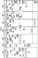
- Fig. 4 is a Gantt chart illustrating an example of setup work in the injection molding system S according to this embodiment.
- the automatic change of the mold unit 800 (the carry-in and carry-out of the mold unit 800) will be described as the setup work by way of example.
- the adjustment of the mold clamping force of the mold unit 800B having been changed, the temperature control of the mold unit 800B, the metering of a molding material performed by the injection unit 300, and the purge of a molding material of the injection unit 300 are performed as other setup work.
- the injection molding machine 10 produces a molding product using the mold unit 800A.
- a temperature controller stop step S104 is performed. Accordingly, the temperature control of the mold unit 800A ends. Furthermore, in a case where the retreat of the plasticizing unit is set in the automatic fall setting portion 773, a plasticizing retreat step S105 is performed. Accordingly, the injection unit 300 is retreated by the moving unit (not shown) . Further, the mold change device 20 performs a step S106 of starting the temperature control of the mold unit 800B that is the next mold.
- the purge of the injection unit 300 is performed as other setup work during the change of a mold.
- the molding material in the injection unit 300 is purged.
- the molding machine-control device 700 controls the injection unit 300 to purge the molding material.
- the purge step S706 may be performed after the coupler advance step S703, or may be performed so as to overlap with the waiting step S704.
Landscapes
- Engineering & Computer Science (AREA)
- Manufacturing & Machinery (AREA)
- Mechanical Engineering (AREA)
- Injection Moulding Of Plastics Or The Like (AREA)
- Moulds For Moulding Plastics Or The Like (AREA)
Abstract
Description
- The present invention relates to an injection molding machine.
- In a case where a mold is changed and molding is performed, a plurality of types of setup work, such as the change of a mold, the mold space adjustment of a mold clamping unit, and the purge of a molding material of an injection unit, are performed in an injection molding machine.
- Japanese Unexamined Patent Publication No.
H7-9524 - Incidentally, since the operation time of the injection molding machine is shortened as setup work is lengthened, there is a concern that the productivity of the injection molding machine may be reduced. For this reason, the shortening of setup work is required.
- Accordingly, an object of the invention is to provide an injection molding machine of which the productivity is improved.
- An injection molding machine according to an aspect of an embodiment includes a mold clamping unit to which a mold unit is attached and a control unit, and the control unit performs other setup work during a change of the mold unit attached to the mold clamping unit.
- According to the invention, it is possible to provide an injection molding machine of which the productivity is improved.
-
-
Fig. 1 is a diagram showing the configuration of an injection molding system according to an embodiment. -
Fig. 2 is an example of a block diagram of the injection molding system according to this embodiment. -
Fig. 3 is an example of a display screen displayed on a display unit. -
Fig. 4 is a Gantt chart illustrating an example of setup work in the injection molding system S according to this embodiment. - An embodiment of the invention will be described below with reference to the drawings . The same or corresponding components will be denoted in the respective drawings by the same or corresponding reference numerals and the description thereof will be omitted.
- An injection molding system S according to an embodiment will be described with reference to
Fig. 1. Fig. 1 is a plan view of the inject ion molding system S according to the embodiment. InFig. 1 , an X-axis direction, a Y-axis direction, and a Z-axis direction are directions perpendicular to each other. The X-axis direction and the Y-axis direction indicate horizontal directions and the Z-axis direction indicates a vertical direction. In a case where amold clamping unit 100 is a horizontal type, the X-axis direction corresponds to mold opening and closing directions and the Y-axis direction corresponds to the width direction of aninjection molding machine 10. A negative side in the Y-axis direction is referred to as an operation side, and a positive side in the Y-axis direction is referred to as a side opposite to the operation side. - The injection molding system S includes the
injection molding machine 10. Further, the injection molding system S includes amold change device 20, aclamping device 30, and anautomatic coupler 40 as peripheral devices. - The
injection molding machine 10 includes amold clamping unit 100, an ejector unit (not shown), aninjection unit 300, a moving unit (not shown), a molding machine-control device 700, and aframe 900. Theframe 900 includes a moldclamping unit frame 910 and aninjection unit frame 920. Each of the moldclamping unit frame 910 and theinjection unit frame 920 is installed on the floor (not shown) through a leveling adjuster (not shown) . The molding machine-control device 700 is disposed in the internal space of theinjection unit frame 920. The respective components of theinjection molding machine 10 will be described below. - In the description of the
mold clamping unit 100, the moving direction of amovable platen 120 in a case where a mold is to be closed (for example, an X-axis positive direction) corresponds to a front side and the moving direction of themovable platen 120 in a case where a mold is to be opened (for example, an X-axis negative direction) corresponds to a rear side. - The
mold clamping unit 100 closes, pressurizes, depressurizes, and opens a mold unit 800. An operation until the end of depressurization from the start of pressurization is also referred to as mold clamping. The mold unit 800 includes astationary mold 810 and amovable mold 820. - The
mold clamping unit 100 is, for example, a horizontal type and the mold opening and closing directions of themold clamping unit 100 correspond to a horizontal direction. Themold clamping unit 100 includes astationary platen 110, amovable platen 120, atoggle support 130, atie bar 140, atoggle mechanism 150, amold clamping motor 160, a motion conversion mechanism (not shown), and a moldspace adjustment mechanism 180. - The
stationary platen 110 is fixed to the moldclamping unit frame 910. Thestationary mold 810 is attached to the surface of thestationary platen 110 facing themovable platen 120. - The
movable platen 120 is disposed so as to be movable with respect to the moldclamping unit frame 910 in the mold opening and closing directions. A guide (not shown) for guiding themovable platen 120 is provided on the moldclamping unit frame 910. Themovable mold 820 is attached to the surface of themovable platen 120 facing thestationary platen 110. In a case where themovable platen 120 is advanced and retreated with respect to thestationary platen 110, the mold unit 800 is closed, pressurized, depressurized, and opened. - The
toggle support 130 is disposed with an interval between thestationary platen 110 and itself, and is placed on the moldclamping unit frame 910 so as to be movable in the mold opening and closing directions. Thetoggle support 130 may be disposed so as to be movable along a guide provided on the moldclamping unit frame 910. The guide for thetoggle support 130 may be common to the guide (not shown) for themovable platen 120. - In this embodiment, the
stationary platen 110 is fixed to the moldclamping unit frame 910 and thetoggle support 130 is disposed so as to be movable with respect to the moldclamping unit frame 910 in the mold opening and closing directions. However, thetoggle support 130 may be fixed to the moldclamping unit frame 910 and thestationary platen 110 may be disposed so as to be movable with respect to the moldclamping unit frame 910 in the mold opening and closing directions. - The
tie bar 140 connects thestationary platen 110 to thetoggle support 130 at intervals in the mold opening and closing directions. A plurality of (for example, four)tie bars 140 may be used. The plurality oftie bars 140 are disposed in parallel to the mold opening and closing directions and extend depending on a mold clamping force . At least onetie bar 140 may be provided with a tie bar strain detector (not shown) that detects the strain of thetie bar 140. The tie bar strain detector (not shown) sends a signal indicating the detection result thereof to the molding machine-control device 700. The detection result of the tie bar strain detector (not shown) may be used for the detection of a mold clamping force, and the like. - The tie bar strain detector (not shown) is used in this embodiment as a mold clamping force detector for detecting a mold clamping force, but a technique of this disclosure is not limited thereto . The mold clamping force detector is not limited to a strain gauge type and may be a piezoelectric type, acapacitive type, a hydraulic type, an electromagnetic type, and the like. A position where the mold clamping force detector is attached is also not limited to the
tie bar 140. - The
toggle mechanism 150 is disposed between themovable platen 120 and thetoggle support 130, and moves themovable platen 120 with respect to thetoggle support 130 in the mold opening and closing directions. Thetoggle mechanism 150 includes acrosshead 151, a pair of link groups, and the like. Each of the pair of link groups includes afirst link 152 and asecond link 153 that are bendably and stretchably connected to each other by a pin or the like. Thefirst link 152 is oscillatingly attached to themovable platen 120 by a pin or the like, and thesecond link 153 is oscillatingly attached to thetoggle support 130 by a pin or the like. Thesecond link 153 is attached to thecrosshead 151 through a third link (not shown). In a case where thecrosshead 151 is advanced and retreated with respect to thetoggle support 130, the first andsecond links movable platen 120 is advanced and retreated with respect to thetoggle support 130. - The configuration of the
toggle mechanism 150 is not limited to the above-mentioned configuration. For example, the number of nodes of each link group is five in the above description but may be four. One end portion of the third link (not shown) may be connected to the node between the first andsecond links - The
mold clamping motor 160 is attached to thetoggle support 130 and operates thetoggle mechanism 150. Themold clamping motor 160 advances and retreats thecrosshead 151 with respect to thetoggle support 130 to bend and stretch the first andsecond links movable platen 120 with respect to thetoggle support 130. Themold clamping motor 160 is directly connected to the motion conversion mechanism (not shown), but may be connected to the motion conversion mechanism (not shown) through a belt, pulleys, and the like. - The motion conversion mechanism (not shown) converts the rotary motion of the
mold clamping motor 160 to the linear motion of thecrosshead 151. The motion conversion mechanism (not shown) includes a screw shaft and a screw nut that is threadedly engaged the screw shaft. Balls or rollers may be interposed between the screw shaft and the screw nut. - The
mold clamping unit 100 performs a mold closing process, a pressurization process, a depressurization process, a mold opening process, and the like under the control of the molding machine-control device 700. - In the mold closing process, the
mold clamping motor 160 is driven to advance thecrosshead 151 to a mold closing completion position at a set movement speed, so that themovable platen 120 is advanced to cause themovable mold 820 to touch thestationary mold 810. The position and the movement speed of thecrosshead 151 are detected using, for example, a mold clampingmotor encoder 161 or the like. The mold clampingmotor encoder 161 detects the rotation of themold clamping motor 160, and sends a signal indicating the detection result thereof to the molding machine-control device 700. - A crosshead position detector for detecting the position of the
crosshead 151 and a crosshead movement speed detector for detecting the movement speed of thecrosshead 151 are not limited to the mold clampingmotor encoder 161, and general detectors can be used. Further, a movable platen position detector for detecting the position of themovable platen 120 and a movable platen movement speed detector for detecting the movement speed of themovable platen 120 are not limited to the mold clampingmotor encoder 161, and general detectors can be used. - In the pressurization process, the
mold clamping motor 160 is further driven to further advance thecrosshead 151 to a mold clamping position from the mold closing completion position and to generate a mold clamping force. A cavity space (not shown) is formed between themovable mold 820 and thestationary mold 810 in a case where the molds are clamped, and theinjection unit 300 fills the cavity space (not shown) with liquid molding material. A molding product is obtained in a case where the molding material filling the cavity space is solidified. - One cavity space (not shown) may be set or a plurality of cavity spaces may be set. In the latter case, a plurality of molding products are obtained at the same time. An insert material may be disposed in a part of the cavity space (not shown) and the other part of the cavity space (not shown) is filled with a molding material. A molding product in which the insert material and the molding material are integrated with each other is obtained.
- In the depressurization process, the
mold clamping motor 160 is driven to retreat thecrosshead 151 to a mold opening start position from the mold clamping position, so that themovable platen 120 is retreated to reduce the mold clamping force. The mold opening start position and the mold closing completion position may be the same position. - In the mold opening process, the
mold clamping motor 160 is driven to retreat thecrosshead 151 to a mold opening completion position from the mold opening start position at a set movement speed, so that themovable platen 120 is retreated to cause themovable mold 820 to be separated from thestationary mold 810. Afterthat, the ejector unit (not shown) ejects the molding product from themovable mold 820. - Set conditions in the mold closing process and the pressurization process are collectively set as a series of set conditions. For example, the movement speeds and the positions (including a mold closing start position, a movement speed switching position, a mold closing completion position, and a mold clamping position) of the
crosshead 151 and mold clamping forces in the mold closing process and the pressurization process are collectively set as a series of set conditions. The mold closing start position, the movement speed switching position, the mold closing completion position, and the mold clamping position are arranged in this order from the rear side toward the front side, and indicate the starting points and the end points of sections in which the movement speeds are set. The movement speed is set for each section. One movement speed switching position may be set or a plurality of movement speed switching positions may be set. The movement speed switching position may not be set. Only one of the mold clamping position and the mold clamping force may be set. - Set conditions in the depressurization process and the mold opening process are also collectively set in the same manner. For example, the movement speeds and the positions (including a mold opening start position, a movement speed switching position, and a mold opening completion position) of the
crosshead 151 in the depressurization process and the mold opening process are collectively set as a series of set conditions. The mold opening start position, the movement speed switching position, and the mold opening completion position are arranged in this order from the front side toward the rear side, and indicate the starting points and the end points of sections in which the movement speeds are set. The movement speed is set for each section. One movement speed switching position may be set or a plurality of movement speed switching positions may be set. The movement speed switching position may not be set. The mold opening start position and the mold closing completion position may be the same position. Further, the mold opening completion position and the mold closing start position may be the same position. - The movement speeds and the positions of the
movable platen 120, and the like may be set instead of the movement speeds and the positions of thecrosshead 151, and the like. Further, a mold clamping force maybe set instead of the position (for example, the mold clamping position) of the crosshead or the position of the movable platen. - Incidentally, the
toggle mechanism 150 amplifies the driving force of themold clamping motor 160 and transmits the amplified driving force to themovable platen 120. The amplification factor of thetoggle mechanism 150 is also referred to as a toggle factor. The toggle factor is changed depending on an angle between the first andsecond links 152 and 153 (hereinafter, also referred to as a "link angle") . The link angle is obtained from the position of thecrosshead 151. In a case where the link angle is 180°, the toggle factor is maximum. - In a case where the space of the mold unit 800 is changed due to the change of the mold unit 800, a change in the temperature of the mold unit 800, or the like, mold space adjustment is performed so that a predetermined mold clamping force is obtained in a case where the molds are clamped. In the mold space adjustment, an interval between the
stationary platen 110 and thetoggle support 130 is adjusted so that the link angle of thetoggle mechanism 150 is a predetermined angle at a point of mold touch time when, for example, themovable mold 820 touches thestationary mold 810. - The
mold clamping unit 100 includes the moldspace adjustment mechanism 180 that performs mold space adjustment by adjusting an interval between thestationary platen 110 and thetoggle support 130. The moldspace adjustment mechanism 180 includes, for example, screw shafts that are formed at the rear end portions of the tie bars 140, screw nuts that are rotatably held by thetoggle support 130 not to be capable of being advanced and retreated, and a mold space adjustment motor that rotates the screw nuts threadedly engaged with the screw shafts. - The screw shaft and the screw nut are provided for each
tie bar 140. The rotational driving force of the mold space adjustment motor may be transmitted to a plurality of screw nuts through a rotational driving force transmission part. The plurality of screw nuts can be rotated in synchronization. It is also possible to individually rotate the plurality of screw nuts by changing the transmission channel of the rotational driving force transmission part. - The rotational driving force transmission part includes, for example, gears and the like. In this case, a driven gear is formed on the outer periphery of each screw nut. A driving gear is attached to the output shaft of the mold space adjustment motor. An intermediate gear, which meshes with a plurality of driven gears and a plurality of driving gears, is rotatably held at the central portion of the
toggle support 130. The rotational driving force transmission part may include a belt, pulleys, and the like instead of the gears. - The operation of the mold
space adjustment mechanism 180 is controlled by the molding machine-control device 700. The molding machine-control device 700 drives the mold space adjustment motor to rotate the screw nuts. As a result, the position of thetoggle support 130, by which the screw nuts are rotatably held not to be capable of being advanced and retreated, with respect to the tie bars 140 is adjusted, so that an interval between thestationary platen 110 and thetoggle support 130 is adjusted. A plurality of mold space adjustment mechanisms may be used in combination. - The interval is detected using a mold space adjustment motor encoder. The mold space adjustment motor encoder detects the amount of rotation and the rotation direction of the mold space adjustment motor, and sends signals indicating the detection results thereof to the molding machine-
control device 700. The detection results of the mold space adjustment motor encoder are used for the monitoring and control of the position of thetoggle support 130 and the interval. A toggle support position detector for detecting the position of thetoggle support 130 and an interval detector for detecting the interval are not limited to the mold space adjustment motor encoder, and general detectors can be used. - The
mold clamping unit 100 of this embodiment is a horizontal type of which mold opening and closing directions correspond to a horizontal direction, but may be a vertical type of which mold opening and closing directions correspond to a vertical direction. - The
mold clamping unit 100 of this embodiment includes themold clamping motor 160 as a drive source, but may include a hydraulic cylinder instead of themold clamping motor 160. Further, themold clamping unit 100 may include a linear motor for opening and closing the molds and may include an electromagnet for clamping the molds. - The
mold clamping unit 100 is covered with acover 190. Thecover 190 is provided with an opening portion that is used to carry in and out the mold unit 800. Further, themold clamping unit 100 is provided with adoor 195 for opening and closing the opening portion of thecover 190. Furthermore, themold clamping unit 100 includes a door opening/closing mechanism 196 for opening/closing thedoor 195. - The ejector unit (not shown) is attached to the
movable platen 120, and is advanced and retreated together with themovable platen 120. The ejector unit (not shown) performs an ejection process under the control of the molding machine-control device 700. In the ejection process, an ejector rod (not shown) is advanced to an ejection position from a waiting position at a set movement speed, so that amovablemember (not shown) is advanced to eject a molding product. After that, an ejector motor (not shown) is driven to retreat the ejector rod (not shown) at a set movement speed and to retreat the movable member (not shown) to the original waiting position. - The
injection unit 300 is disposed so as to be capable of being advanced and retreated with respect to the mold unit 800. Theinjection unit 300 touches the mold unit 800, and fills the cavity space (not shown) formed in the mold unit 800 with a molding material. Theinjection unit 300 includes, for example, a cylinder, a nozzle, a screw, a plasticizing motor, an injection motor, a pressure detector, and the like. - The moving unit (not shown) advances and retreats the
injection unit 300 with respect to the mold unit 800. Further, the moving unit (not shown) presses the nozzle against the mold unit 800 and causes nozzle touch pressure. - The molding machine-
control device 700 is formed of, for example, a computer and includes a central processing unit (CPU), a storage medium, such as a memory, an input interface, and an output interface. The molding machine-control device 700 performs various types of control by causing the CPU to execute a program that is stored in the storage medium. Further, the molding machine-control device 700 receives a signal from the outside through the input interface, and transmits a signal to the outside through the output interface. - Furthermore, the
injection molding machine 10 includes anoperation unit 750 and adisplay unit 760. Theoperation unit 750 receives an input operation performed by a user, and outputs a signal corresponding to the input operation to the molding machine-control device 700. Thedisplay unit 760 displays a display screen, which corresponds to the input operation of theoperation unit 750, under the control of the molding machine-control device 700. Thedisplay unit 760 may be formed of a touch panel, and the touch panel may form at least a part of theoperation unit 750. - Further, the
injection molding machine 10 is provided with the clampingdevice 30 that allows the mold unit 800 to be detachably attached to themold clamping unit 100. The clampingdevice 30 includes a stationary-side clamping device 30a and a movable-side clamping device 30b. The stationary-side clamping device 30a is fixed to thestationary platen 110, and thestationary mold 810 is detachably clamped by the stationary-side clamping device 30a. The movable-side clamping device 30b is fixed to themovable platen 120, and themovable mold 820 is detachably clamped by the movable-side clamping device 30b. The clampingdevice 30 is controlled by the molding machine-control device 700, and the mold unit 800 is attached to or detached from the clampingdevice 30. The clampingdevice 30 may be a clamping device including a mechanical lock mechanism that is operated by hydraulic pressure, air pressure, or the like, may be a clamping device that clamps molds by a magnetic force, and is not limited. - Further, the clamping
device 30 may include a positioning pin (not shown) and a drive unit (not shown) that drives the positioning pin. Since theclamping device 30 clamps the mold unit 800 by the stationary-side clamping device 30a and the movable-side clamping device 30b after the positioning pin is inserted into the mold unit 800, the clampingdevice 30 can clamp the mold unit 800 in a state where theclamping device 30 is positioned. - Further, the
injection molding machine 10 is provided with theautomatic coupler 40. Theautomatic coupler 40 of theinjection molding machine 10 is connected to a connectingpart 860 of the mold unit 800 to be described later in a case where the mold unit 800 is attached to theinjection molding machine 10. Specifically, theautomatic coupler 40 includes a drive unit (not shown) and is adapted to be capable of being connected (advanced) to and released (retreated) from the connectingpart 860 of the mold unit 800. Accordingly, for example, sinceaheater (not shown) of the mold unit 800 is energized from theinjection molding machine 10, the temperature of the mold unit 800 can be controlled. Further, for example, the mold unit 800 may be connected to a temperature controller (not shown), which supplies a heating medium, through theautomatic coupler 40. Accordingly, a heating medium can be supplied to a flow channel (not shown) provided in the mold unit 800. Theautomatic coupler 40 includes a drive unit (not shown) and is adapted to be capable of being connected (advanced) to and released (retreated) from the connectingpart 860 of the mold unit 800. - The
mold change device 20 includes a travelingrail 21, abogie22, abridge23, drivingrollers 24, a change device-control device 26, and afence 27. - The
bogie 22 moves on a travelingrail 21. The movement of thebogie 22 is controlled by the change device-control device 26. Further, thebogie 22 includes afirst placement part 221A on which the mold unit 800 is placed and asecond placement part 221B. Furthermore, thebogie22 reciprocates between a reference position (waiting position) shown inFig. 1 and a delivery position P where the mold unit 800 is delivered to thebridge 23. - A
conveyor unit 222A is provided on the upper surface of thefirst placement part 221A. Theconveyor unit 222A is, for example, a driving roller conveyor and is controlled by the change device-control device 26. Theconveyor unit 222A is used in a case where the mold unit 800 is carried in thefirst placement part 221A or a case where the mold unit 800 is carried out of thefirst placement part 221A. - Further, the
first placement part 221A is provided with anautomatic coupler 223A. Theautomatic coupler 223A is connected to the connectingpart 860 of the mold unit 800 to be described later in a case where the mold unit 800 is placed on thefirst placement part 221A. Accordingly, for example, since the heater (not shown) of the mold unit 800 is energized from thebogie 22, the temperature of the mold unit 800 can be preliminarily controlled. - As in the
first placement part 221A, thesecond placement part 221B is provided with aconveyor unit 222B and anautomatic coupler 223B. - The
bridge 23 is disposed between thebogie 22 and theinjection molding machine 10, and is used in a case where the mold unit 800 is transported. A conveyor is provided on the upper surface of thebridge 23, and is controlled by the change device-control device 26. - The driving
rollers 24 are disposed under thestationary platen 110 and themovable platen 120 in theinjection molding machine 10. The drivingrollers 24 are used in a case where the mold unit 800 carried in theinjection molding machine 10 is transported to a position where the mold unit 800 is to be clamped or a case where the mold unit 800 is carried out of theinjection molding machine 10. Further, thestationary platen 110 and themovable platen 120 are provided with the drivingrollers 24, respectively. Both end portions of the mold unit 800 are placed on the drivingrollers 24 and the drivingrollers 24 transport the mold unit 800. A molding product ejected by the ejector unit can pass between the drivingrollers 24. The drivingrollers 24 are controlled by the change device-control device 26. - Further, the
fence 27 is provided around the travelingrail 21 and thebogie 22, and prevents a worker from entering the movement range of thebogie 22. - The mold unit 800 includes the
stationary mold 810, themovable mold 820, and the connectingpart 860. - The connecting
part 860 is connected to theautomatic coupler 40 of theinjection molding machine 10 or theautomatic couplers bogie 22. -
Fig. 2 is a block diagram of the injection molding system S according to this embodiment. - The molding machine-
control device 700 of theinjection molding machine 10 includes astorage unit 701 and acommunication port 702. - A plurality of molding conditions are stored in the
storage unit 701. The molding conditions include information about the mold unit 800 ("mold space" of the mold unit 800, "mold clamping force-generation-mold pressure position" to be described later, and the like), the metering conditions of theinjection unit 300, operating conditions for each mode selected in an automaticfall setting portion 773 to be described later, and the like. Further, an identification code is assigned to each molding condition. - The
communication port 702 is connected to acommunication port 711 of asequencer 710. - The
sequencer 710 includes acommunication port 711, acommunication port 712, and an I/O port 713. Thecommunication port 711 is communicably connected to thecommunication port 702 of the molding machine-control device 700. Thesequencer 710 is a device that converts an input signal and outputs the converted signal on the basis of preset logic. - The
communication port 712 is connected to acommunication port 721 of the change device-control device 26 provided in themold change device 20. According to this configuration, the molding machine-control device 700 can command themold change device 20 to operate through thesequencer 710. Further, the operating state of themold change device 20 is input to the molding machine-control device 700 through thesequencer 710. - The I/
O port 713 is connected to an I/O port 722 of theclamping device 30. According to this configuration, the molding machine-control device 700 can command theclamping device 30 to operate through thesequencer 710. Further, the operating state of theclamping device 30 is input to the molding machine-control device 700 through thesequencer 710. - Furthermore, the I/
O port 713 is connected to an I/O port 723 of theautomatic coupler 40. According to this configuration, the molding machine-control device 700 can command theautomatic coupler 40 to operate through thesequencer 710. Further, the operating state of theautomatic coupler 40 is input to the molding machine-control device 700 through thesequencer 710. - As described above, the molding machine-
control device 700 of theinjection molding machine 10 can control the peripheral devices (themold change device 20, the clampingdevice 30, and the automatic coupler 40) and can acquire the operating states of the peripheral devices. -
Fig. 3 is an example of a display screen displayed on thedisplay unit 760. The display screen shown inFig. 3 is an example of a display screen that displays settings and actual values (operating states) for setup work. Here, the setup work is work that allows the mass production of molding products to be performed by theinjection molding machine 10. For example, the setup work includes the change of a mold (the attachment of a mold), the adjustment of the mold clamping force of the mold unit 800, the temperature control of the mold unit 800, the metering of a molding material performed by theinjection unit 300, the purge of a molding material of theinjection unit 300, and the like. - The display screen includes a
display portion 761 that displays the operating state of theinjection molding machine 10. Further, the display screen includes adisplay portion 762 that shows information about themold change device 20. Thedisplay portion 762 includes an operating state display portion 762a that shows the operating state of themold change device 20, and acommand display portion 762b that shows a command to be given to themold change device 20. Likewise, the display screen includes adisplay portion 763 that shows information about theclamping device 30. Thedisplay portion 763 includes an operatingstate display portion 763a that shows the operating state of theclamping device 30, and acommand display portion 763b that shows a command to be given to theclamping device 30. Furthermore, the display screen includes adisplay portion 764 that shows information about theautomatic coupler 40. Thedisplay portion 764 includes an operatingstate display portion 764a that shows the operating state of theautomatic coupler 40, and acommand display portion 764b that shows a command to be given to theautomatic coupler 40. The progress state of setup work is displayed on the display screen as described above. - The display screen includes a condition
call setting portion 771. Here, the identification codes and the molding conditions are stored in thestorage unit 701 in association with each other. The conditioncall setting portion 771 is adapted so that an identification code used to call a molding condition required for the production of a molding product using the next mold unit 800B can be input to the conditioncall setting portion 771 before the production of a molding product using the current mold unit 800A is finished. Accordingly, the production of a molding product using the next mold unit 800B can be reserved before the production of a molding product using the current mold unit 800A is finished. In an example shown inFig. 3 , the condition name of a molding condition and the number of a folder and the number of a file in which the molding condition is stored are displayed in the conditioncall setting portion 771 in a case where an identification number as an identification code is input to an input field (not shown). - The display screen includes a temperature controller-interlocking
setting portion 772, an automaticfall setting portion 773, and a next mold-operation setting portion 774. Here, theinjection molding machine 10 determines that production has ended at a point of time when a filling operation required for final molding is finished in a case where final molding for the production of a molding product using the current mold unit 800A is performed. The temperature controller-interlockingsetting portion 772 is adapted to be capable of selecting whether or not to stop the temperature controller at this point of time. Further, the automaticfall setting portion 773 is adapted to be capable of selecting whether or not to retreat theinjection unit 300 serving as a plasticizing unit at this point of time. Furthermore, the next mold-operation setting portion 774 can set whether or not to perform the metering operation of theinjection unit 300 at this point of time. Further, the display screen includes a next mold-meteringcondition display portion 775. The metering condition of the next mold (mold unit 800B) included in the molding condition corresponding to the identification code input to the conditioncall setting portion 771 is displayed in the next mold-meteringcondition display portion 775. - The display screen includes a next mold-space
condition display portion 776. Here, mold space positions for generating mold clamping forces are stored in the molding conditions stored in thestorage unit 701. Further, the mold space of the mold unit 800 is stored in the molding conditions. The mold clamping force-generation-mold space position and the mold space of the next mold (mold unit 800B) included in the molding condition corresponding to the identification code input to the conditioncall setting portion 771 are displayed in the next mold-spacecondition display portion 776. - Furthermore, the display screen includes a current mold-space
condition display portion 777. The mold clamping force-generation-mold space position and the mold space of the current mold (mold unit 800A) included in the current molding condition are displayed in the current mold-spacecondition display portion 777. Moreover, an adjustment distance (+α) from the molding condition is displayed in the current mold-spacecondition display portion 777. Further, whether or not the adjustment of a mold clamping force has been completed is displayed in the current mold-spacecondition display portion 777. - Furthermore, the display screen includes an unclamped mold opening
distance setting portion 778 and a mold change-mold opening/closingspeed setting portion 779. The unclamped mold openingdistance setting portion 778 is adapted so that a mold opening distance at the time of unclamping can be input to the unclamped mold openingdistance setting portion 778. The mold change-mold opening/closingspeed setting portion 779 is adapted so that a mold opening/closing speed during the change of a mold can be input to the mold change-mold opening/closingspeed setting portion 779. -
Fig. 4 is a Gantt chart illustrating an example of setup work in the injection molding system S according to this embodiment. Here, the automatic change of the mold unit 800 (the carry-in and carry-out of the mold unit 800) will be described as the setup work by way of example. Further, the adjustment of the mold clamping force of the mold unit 800B having been changed, the temperature control of the mold unit 800B, the metering of a molding material performed by theinjection unit 300, and the purge of a molding material of theinjection unit 300 are performed as other setup work. InFig. 4 , theinjection molding machine 10 produces a molding product using the mold unit 800A. Further, it will be described that thebogie 22 is positioned at the waiting position, the mold unit 800A is attached to theinjection molding machine 10, the mold unit 800B is placed on thefirst placement part 221A of thebogie 22, and thesecond placement part 221B is in an empty state. - A current mold-production step S100 includes a production step S101 and a production-final shot step S102. The production step S101 is a step of producing a molding product by the current mold unit 800A. The production-final shot step S102 is a step of finally producing a molding product by the current mold unit 800A.
- Here, in a case where automatic fall is set in the automatic
fall setting portion 773, theinjection molding machine 10 determines that production has ended at a point of time when a filling operation required for final molding is finished and performs a next mold-metering step S103. Here, a metering operation of theinjection unit 300 is performed on the basis of the next mold-metering condition of the next mold-metering condition display portion 775 (a molding condition corresponding to an identification code set in the condition call setting portion 771). That is, setup work for the next mold unit 800B is performed during the production of a molding product using the current mold unit 800A. - Further, in a case where the interlocking of the temperature controller is set in the temperature controller-interlocking
setting portion 772, a temperature controller stop step S104 is performed. Accordingly, the temperature control of the mold unit 800A ends. Furthermore, in a case where the retreat of the plasticizing unit is set in the automaticfall setting portion 773, a plasticizing retreat step S105 is performed. Accordingly, theinjection unit 300 is retreated by the moving unit (not shown) . Further, themold change device 20 performs a step S106 of starting the temperature control of the mold unit 800B that is the next mold. Here, a heating medium is supplied to the mold unit 800B placed on thebogie 22 through theautomatic coupler 223A and the connectingpart 860, so that the temperature of the mold unit 800B is preliminarily controlled. In a case where the preliminary temperature control of the mold unit 800B ends, a step S202 of stopping the temperature control of the mold unit 800B, which is the next mold, is performed. - In a preparation step S200, an operator works (S201) . For example, the operator checks the mold unit 800B to be carried in. Further, the operator checks the opening locking of the mold units 800A and 800B. Furthermore, the operator checks whether or not the preliminary temperature control of the mold unit 800B has ended. In a case where the checks of these end, the operator operates a switch that is provided on the
operation unit 750 and used to perform the automatic change of the mold unit 800. - Here, automatic mold change includes a mold detachment step S300 of detaching the mold unit 800A from the
injection molding machine 10, a mold carry-out step S400 of carrying the mold unit 800A out of theinjection molding machine 10, a carry-in preparation step S500 performed before carrying the mold unit 800B in theinjection molding machine 10, a mold carry-in step S600 of carrying the mold unit 800B in theinjection molding machine 10, and a mold attachment step S700 of attaching the mold unit 800B to theinjection molding machine 10. - The mold detachment step S300 includes a coupler retreat stepS301, amolddetachment (unclamping) stepS302, amoldopening stepS303, a positioning pin return step S304, and a bogie movement step S305. The coupler retreat step S301, the mold detachment (unclamping) step S302, and the mold opening step S303 are sequentially performed.
- In the coupler retreat step S301, the
automatic coupler 40 is retreated to release the connection between theautomatic coupler 40 and the connectingpart 860 of the mold unit 800. Specifically, the molding machine-control device 700 transmits a retreat command to theautomatic coupler 40 through thesequencer 710. In a case where theautomatic coupler 40 is retreated, theautomatic coupler 40 transmits an operating state to the molding machine-control device 700 through thesequencer 710. - In the mold detachment (unclamping) step S302, the clamping of the mold unit 800A performed by the clamping
device 30 is released. Specifically, the molding machine-control device 700 transmits an unclamping command to theclamping device 30 through thesequencer 710. In a case where the clamping of theclamping device 30 is released, the clampingdevice 30 transmits an operating state to the molding machine-control device 700 through thesequencer 710. - In the mold opening step S303, an interval between the
stationary platen 110 and themovable platen 120 is increased so that the mold unit 800A can be carried out. Specifically, the molding machine-control device 700 controls themold clamping motor 160 of themold clamping unit 100 to retreat themovable platen 120 with a mold opening distance set in the unclamped mold openingdistance setting portion 778 and to increase an interval between thestationary platen 110 and themovable platen 120. - In the positioning pin return step S304, the positioning pin is removed from the mold unit 800A. Specifically, themolding machine-
control device 700 transmits a positioning pin return command to theclamping device 30 through thesequencer 710. In a case where the positioning pin is removed, the clampingdevice 30 transmits an operating state to the molding machine-control device 700 through thesequencer 710. The positioning pin return step S304 may be performed so as to overlap with the mold opening step S303. - In the bogie movement step S305, the
bogie 22 is moved so that thesecond placement part 221B is moved to the delivery position P. Specifically, the molding machine-control device 700 transmits a command to the change device-control device 26 of themold change device 20. The change device-control device 26 causes thebogie 22 to move on the basis of the command. In a case where the movement of thebogie 22 is completed, the change device-control device 26 transmits an operating state to the molding machine-control device 700. The bogie movement step S305 may be performed so as to overlap with the coupler retreat step S301, the mold detachment (unclamping) step S302, and the mold opening step S303. - The mold carry-out step S400 includes a door opening step S401, a mold carry-out operation step S402, a door closing step S403, and a bogie movement step S404. The door opening step S401, the mold carry-out operation step S402, and the door closing step S403 are sequentially performed.
- In the door opening step S401, the
door 195 is opened. Specifically, the molding machine-control device 700 controls the door opening/closing mechanism 196 to open thedoor 195. - In the mold carry-out operation step S402, the mold unit 800A is carried out. Specifically, the molding machine-
control device 700 transmits a command to carry the mold unit out to the mold change device 20 (change device-control device 26) through thesequencer 710. The change device-control device 26 controls the drivingrollers 24 and theconveyor unit 222B to place the mold unit 800A on thesecond placement part 221B. In a case where the carry-out of the mold unit 800A is completed, the change device-control device 26 transmits an operating state to the molding machine-control device 700. - In the door closing step S403, the
door 195 is closed. Specifically, the molding machine-control device 700 controls the door opening/closing mechanism 196 to close thedoor 195. - In the bogie movement step S404, the
bogie 22 is moved so that thefirst placement part 221A is moved to the delivery position P. Specifically, the molding machine-control device 700 transmits a command to the change device-control device 26 of themold change device 20. The change device-control device 26 causes thebogie 22 to move on the basis of the command. In a case where the movement of thebogie 22 is completed, the change device-control device 26 transmits an operating state to the molding machine-control device 700. The bogie movement step S404 may be performed after the mold carry-out operation step S402, or may be performed so as to overlap with the door closing step S403 and the carry-in preparation step S500. - In the carry-in preparation step S500, the bogie movement step S404, which is a part of mold change work, is continuously performed. Further, the adjustment of the mold clamping force of the mold unit 800B, which is the next mold, is performed as other setup work during the change of a mold. Here, the carry-in preparation step S500 includes a next mold-condition call step S501 and a mold space adjustment step S502. The next mold-condition call step S501 and the mold space adjustment step S502 are sequentially performed.
- In the next mold-condition call step S501, the condition of the mold unit 800B to be carried in the
injection molding machine 10 next is called. Specifically, the molding machine-control device 700 calls a molding condition, which corresponds to an identification code set in the conditioncall setting portion 771, from thestorage unit 701. - In the mold space adjustment step S502, the
mold clamping unit 100 is adjusted on the basis of the molding condition of the mold unit 800B called in the next mold-condition call step S501. Specifically, the molding machine-control device 700 controls the moldspace adjustment mechanism 180 of themold clamping unit 100 to adjust an interval between thestationary platen 110 and thetoggle support 130 on the basis of a mold clamping force-generation-mold space position displayed in the next mold-spacecondition display portion 776. - The mold carry-in step S600 includes a door opening step S601, a mold carry-in operation step S602, a door closing step S603, a positioning pin insertion step S604, and a bogie movement step S605. The door opening step S601, the mold carry-in operation step S602, and the door closing step S603 are sequentially performed.
- In the door opening step S601, the
door 195 is opened. Specifically, the molding machine-control device 700 controls the door opening/closing mechanism 196 to open thedoor 195. - In the mold carry-in operation step S602, the mold unit 800B is carried in. Specifically, the molding machine-
control device 700 transmits a command to carry the mold unit in to the mold change device 20 (change device-control device 26) through thesequencer 710. The change device-control device 26 controls the drivingrollers 24 and theconveyor unit 222A to carry the mold unit 800B in themold clamping unit 100 from thefirst placement part 221A. In a case where the carry-in of the mold unit 800B is completed, the change device-control device 26 transmits an operating state to the molding machine-control device 700. - In the door closing step S603, the
door 195 is closed. Specifically, the molding machine-control device 700 controls the door opening/closing mechanism 196 to close thedoor 195. - In the positioning pin insertion step S604, the positioning pin is inserted into the mold unit 800B. Specifically, the molding machine-
control device 700 transmits a command to insert the positioning pin to theclamping device 30 through thesequencer 710. In a case where the positioning pin is inserted, the clampingdevice 30 transmits an operating state to the molding machine-control device 700 through thesequencer 710. The positioning pin insertion step S604 may be performed so as to overlap with the mold carry-in operation step S602. - In the bogie movement step S605, the
bogie 22 is moved to the waiting position (seeFig. 1 ). Specifically, the molding machine-control device 700 transmits a command to the change device-control device 26 of themold change device 20. The change device-control device 26 causes thebogie 22 to move on the basis of the command. In a case where the movement of thebogie 22 is completed, the change device-control device 26 transmits an operating state to the molding machine-control device 700. The bogie movement step S605 may be performed after the mold carry-in operation step S602, or may be performed so as to overlap with the door closing step S603 and the mold attachment step S700. - The mold attachment step S700 includes a mold closing step S701, a mold attachment (clamping) step S702, a coupler advance step S703, a waiting step S704, a temperature controller start step S705, and a purge step S706. The mold closing step S701, the mold attachment (clamping) step S702, the coupler advance step S703, and the waiting step S704 are sequentially performed.
- In the mold closing step S701, an interval between the
stationary platen 110 and themovable platen 120 is reduced so that the mold unit 800B is pinched. Specifically, the molding machine-control device 700 controls themold clamping motor 160 of themold clamping unit 100 to advance themovable platen 120 and to reduce an interval between thestationary platen 110 and themovable platen 120. - In the mold attachment (clamping) step S702, the mold unit 800B is clamped by the clamping
device 30. Specifically, the molding machine-control device 700 transmits a clamping command to theclamping device 30 through thesequencer 710. In a case where the mold unit 800B is clamped by the clampingdevice 30, the clampingdevice 30 transmits an operating state to the molding machine-control device 700 through thesequencer 710. - In the coupler advance step S703, the
automatic coupler 40 is advanced so that theautomatic coupler 40 and the connectingpart 860 of the mold unit 800 are connected to each other. Specifically, the molding machine-control device 700 transmits an advance command to theautomatic coupler 40 through thesequencer 710. In a case where theautomatic coupler 40 is advanced, theautomatic coupler 40 transmits an operating state to the molding machine-control device 700 through thesequencer 710. - In the waiting step S704, the injection molding machine waits until all the setup work is completed after the change of a mold is completed.
- Further, the temperature control of the mold unit 800B is performed as other setup work during the change of a mold. The temperature controller start step S705 is a step of starting the temperature controller (not shown) to control the temperature of the mold unit 8 00B. Specifically, the molding machine-
control device 700 transmits a start command to the temperature controller (not shown) through thesequencer 710. The temperature controller supplies temperature control fluid to the mold unit 800B through theautomatic coupler 40 and the connectingpart 860. The temperature controller start step S705 may be performed after the coupler advance step S703, or may be performed so as to overlap with the waiting step S704. - Furthermore, the purge of the
injection unit 300 is performed as other setup work during the change of a mold. In the purge step S706, the molding material in theinjection unit 300 is purged. Specifically, the molding machine-control device 700 controls theinjection unit 300 to purge the molding material. The purge step S706 may be performed after the coupler advance step S703, or may be performed so as to overlap with the waiting step S704. - According to the
injection molding machine 10 of this embodiment, other setup work can be performed during the change of a mold as described above. Accordingly, since work time for setup work can be shortened, a period in which theinjection molding machine 10 is stopped can be shortened. Therefore, the productivity of theinjection molding machine 10 can be improved. - Specifically, the
injection molding machine 10 according to this embodiment performs the adjustment of the mold clamping force of the mold unit 800B in advance in a time before the next mold unit 800B is carried in after the previous mold unit 800A is carried out during the change of a mold. Positions where a mold clamping force is generated are stored in advance together with the molding conditions. Further, the molding condition of the next mold is input in advance. Accordingly, work time for setup work can be shortened in comparison with a case where the adjustment of a mold clamping force is performed after the change of a mold. Furthermore, since the adjustment of a mold clamping force can be performed on the basis of the molding condition of the next mold preset in the conditioncall setting portion 771, time for the adjustment of a mold clamping force can be shortened. - The adjustment of a mold clamping force may be performed after the mold unit 800B is attached to the
mold clamping unit 100. Accordingly, a mold clamping force can be accurately adjusted. Further, since the adjustment of a mold clamping force is performed in advance in the mold space adjustment step S502, time required for the adjustment of a mold clamping force can be shortened. - Furthermore, the temperature controller start step S705 and the purge step S706 are started so as to overlap with the bogie movement step S605. Accordingly, work time for setup work can be shortened.
- The injection molding system S according to the embodiment and the like have been described above, but the invention is not limited to the above-mentioned embodiment and the like and can have various modifications and improvements without departing from the scope of the invention disclosed in claims.
- It has been described that other setup work overlaps during the change of a mold since other setup work is started and ended before the change of a mold and other setup work is started during the change of a mold. However, the invention is not limited thereto. Other setup work may be started before the change of a mold and other setup work may end during the change of a mold so that setup work overlaps during the change of a mold. For example, the automatic change of a take-out machine chuck plate (not shown. A take-out machine is a device for automatically taking out a molding product and the take-out machine chuck plate is a part that pinches a product provided at the tip portion of the take-out machine) may be performed. Accordingly, work time for setup work can be shortened.
- Further, other setup work, which is performed so as to overlap with the change of a mold, is not limited to the above-mentioned work, and operations for automatically changing the operations or conditions of peripheral devices required for molding or setup work may be performed.
-
- S:
- injection molding system
- 100:
- mold clamping unit
- 10:
- injection molding machine
- 20:
- mold change device
- 22:
- bogie
- 26:
- change device-control device
- 30:
- clamping device
- 40:
- automatic coupler
- 30a, 30b:
- clamping device
- 195:
- door
- 196:
- door opening/closing mechanism
- 700:
- molding machine-control device (control unit)
- 701:
- storage unit
- 750:
- operation unit
- 760:
- display unit
- 800:
- mold unit
- P:
- delivery position
Claims (7)
- An injection molding machine (10) comprising:a mold clamping unit (100) to which a mold unit (800) is attached; anda control unit (700),wherein the control unit (700) performs other setup work during a change of the mold unit (800) attached to the mold clamping unit (100).
- The injection molding machine (10) according to claim 1,
wherein the control unit (700) starts other setup work during the change of the mold unit (800) attached to the mold clamping unit (100). - The injection molding machine (10) according to claim 1 or 2,
wherein the control unit (700) ends other setup work during the change of the mold unit (800) attached to the mold clamping unit (100). - The injection molding machine (10) according to any one of claims 1 to 3, further comprising:a mold clamping force-adjustment mechanism that adjusts a mold clamping force depending on the mold unit (800) attached to the mold clamping unit (100),wherein the control unit (700) adjusts a mold clamping force depending on a next mold unit (800B) during the change of the mold unit (800).
- The injection molding machine (10) according to claim 4,
wherein the control unit (700) adjusts a mold clamping force depending on the next mold unit (800B) before the next mold unit (800B) is carried in after the current mold unit (800A) is carried out. - The injection molding machine (10) according to any one of claims 1 to 5, further comprising:an injection unit (300) that injects a molding material into the mold unit (800),wherein the control unit (700) purges the molding material of the injection unit (300) during the change of the mold unit (800) .
- The injection molding machine (10) according to any one of claims 1 to 5, further comprising:a temperature controller that controls a temperature of the mold unit (800),wherein the control unit (700) starts controlling the temperature of a next mold unit (800B) during the change of the mold unit (800).
Applications Claiming Priority (1)
| Application Number | Priority Date | Filing Date | Title |
|---|---|---|---|
| JP2020065110A JP2021160275A (en) | 2020-03-31 | 2020-03-31 | Injection molding machine |
Publications (2)
| Publication Number | Publication Date |
|---|---|
| EP3888871A1 true EP3888871A1 (en) | 2021-10-06 |
| EP3888871B1 EP3888871B1 (en) | 2022-11-02 |
Family
ID=75111424
Family Applications (1)
| Application Number | Title | Priority Date | Filing Date |
|---|---|---|---|
| EP21163581.8A Active EP3888871B1 (en) | 2020-03-31 | 2021-03-19 | Injection molding machine |
Country Status (3)
| Country | Link |
|---|---|
| EP (1) | EP3888871B1 (en) |
| JP (2) | JP2021160275A (en) |
| CN (1) | CN113459387B (en) |
Cited By (1)
| Publication number | Priority date | Publication date | Assignee | Title |
|---|---|---|---|---|
| US12521927B2 (en) | 2022-04-11 | 2026-01-13 | The Japan Steel Works, Ltd. | Operation screen of magnet clamp, injection molding machine, and injection molding machine system |
Families Citing this family (1)
| Publication number | Priority date | Publication date | Assignee | Title |
|---|---|---|---|---|
| JP7500250B2 (en) * | 2020-03-31 | 2024-06-17 | 住友重機械工業株式会社 | Injection molding machine and method for controlling the same |
Citations (5)
| Publication number | Priority date | Publication date | Assignee | Title |
|---|---|---|---|---|
| JPS57129629U (en) * | 1981-02-09 | 1982-08-12 | ||
| JPH04185411A (en) * | 1990-11-19 | 1992-07-02 | Sekisui Chem Co Ltd | Mold-replacement purging method in injection molding machine |
| JPH079524A (en) | 1993-06-28 | 1995-01-13 | Toyo Mach & Metal Co Ltd | Injection molding machine control system |
| JP2010105330A (en) * | 2008-10-31 | 2010-05-13 | Fanuc Ltd | Controller of injection molding machine with production change-over function |
| JP6441272B2 (en) * | 2016-08-23 | 2018-12-19 | 株式会社名機製作所 | Mold rotary injection molding equipment |
Family Cites Families (8)
| Publication number | Priority date | Publication date | Assignee | Title |
|---|---|---|---|---|
| JPS57103829A (en) * | 1980-12-20 | 1982-06-28 | Hitachi Ltd | Automatic operation control system of injection molding apparatus |
| JP2573239B2 (en) * | 1987-08-26 | 1997-01-22 | マツダ株式会社 | Changeover equipment in injection molding |
| JP2709992B2 (en) * | 1992-02-14 | 1998-02-04 | ファナック株式会社 | Injection molding apparatus provided with a purging method and a mechanism therefor |
| JP2002001771A (en) * | 2000-06-26 | 2002-01-08 | Sumitomo Wiring Syst Ltd | System for replacement of injection mold |
| JP2002316323A (en) * | 2001-04-19 | 2002-10-29 | Sanko Gosei Ltd | Method and apparatus for replacing mold of resin molding machine |
| JP2003175536A (en) * | 2001-12-12 | 2003-06-24 | Ube Machinery Corporation Ltd | Mold clamping force setting system for injection molding |
| JP5450344B2 (en) * | 2010-10-15 | 2014-03-26 | 東芝機械株式会社 | Mold clamping apparatus and control method thereof |
| JP2019177660A (en) * | 2018-03-30 | 2019-10-17 | 住友重機械工業株式会社 | Injection molding machine and injection molding method |
-
2020
- 2020-03-31 JP JP2020065110A patent/JP2021160275A/en active Pending
-
2021
- 2021-01-06 CN CN202110011362.0A patent/CN113459387B/en active Active
- 2021-03-19 EP EP21163581.8A patent/EP3888871B1/en active Active
-
2024
- 2024-06-05 JP JP2024091718A patent/JP7764541B2/en active Active
Patent Citations (5)
| Publication number | Priority date | Publication date | Assignee | Title |
|---|---|---|---|---|
| JPS57129629U (en) * | 1981-02-09 | 1982-08-12 | ||
| JPH04185411A (en) * | 1990-11-19 | 1992-07-02 | Sekisui Chem Co Ltd | Mold-replacement purging method in injection molding machine |
| JPH079524A (en) | 1993-06-28 | 1995-01-13 | Toyo Mach & Metal Co Ltd | Injection molding machine control system |
| JP2010105330A (en) * | 2008-10-31 | 2010-05-13 | Fanuc Ltd | Controller of injection molding machine with production change-over function |
| JP6441272B2 (en) * | 2016-08-23 | 2018-12-19 | 株式会社名機製作所 | Mold rotary injection molding equipment |
Cited By (1)
| Publication number | Priority date | Publication date | Assignee | Title |
|---|---|---|---|---|
| US12521927B2 (en) | 2022-04-11 | 2026-01-13 | The Japan Steel Works, Ltd. | Operation screen of magnet clamp, injection molding machine, and injection molding machine system |
Also Published As
| Publication number | Publication date |
|---|---|
| CN113459387B (en) | 2023-07-25 |
| JP2021160275A (en) | 2021-10-11 |
| JP7764541B2 (en) | 2025-11-05 |
| CN113459387A (en) | 2021-10-01 |
| JP2024107142A (en) | 2024-08-08 |
| EP3888871B1 (en) | 2022-11-02 |
Similar Documents
| Publication | Publication Date | Title |
|---|---|---|
| JP7764541B2 (en) | Control device and mold device setup method | |
| KR101419812B1 (en) | Compression molding apparatus and compression molding method of resin molded product comprising fiber | |
| US7886806B2 (en) | Method for removing a casted part for use in a die casting machine | |
| CA2644229C (en) | Integrated system for producing composites | |
| JP6944077B2 (en) | Injection molding machine and control method of injection molding machine | |
| JP7395373B2 (en) | Injection molding machine | |
| CN110871537B (en) | Injection molding system | |
| JP6830846B2 (en) | Injection molding machine | |
| US8229591B2 (en) | Method for sequence programming of an injection molding cycle of an injection molding machine | |
| EP3888875B1 (en) | Injection molding machine | |
| JP7579285B2 (en) | Injection molding system, conveying device, and mold exchange method | |
| JP2019177660A (en) | Injection molding machine and injection molding method | |
| JP3860999B2 (en) | Mold clamping device and mold clamping method of injection compression molding machine | |
| JP2023037425A (en) | Mold changing system for vertical rotary injection molding machine and mold changing method for vertical rotary injection molding machine | |
| JP2022049402A (en) | Mold, injection molding system, and method of manufacturing molded product | |
| JP4425691B2 (en) | Mold apparatus for injection molding machine and injection molding method | |
| CN117429024A (en) | Ultrasonic plasticizing injection molding equipment and control method | |
| JP2008229897A (en) | Injection molding method and injection molding machine | |
| CN105922499A (en) | Injection Molding Machine And Operation Screen Of Injection Molding Machine | |
| JP7665053B2 (en) | Manufacturing methods using shuttle molding and overmolding | |
| CN119502277A (en) | Mold clamping device and control method of mold clamping device | |
| JPH08285B2 (en) | Die height adjustment device | |
| JP2000254951A (en) | Injection molding machine for fluororesin article | |
| KR20180013364A (en) | An injection molding machine | |
| JPH03251421A (en) | Injection molding machine |
Legal Events
| Date | Code | Title | Description |
|---|---|---|---|
| PUAI | Public reference made under article 153(3) epc to a published international application that has entered the european phase |
Free format text: ORIGINAL CODE: 0009012 |
|
| STAA | Information on the status of an ep patent application or granted ep patent |
Free format text: STATUS: EXAMINATION IS IN PROGRESS |
|
| 17P | Request for examination filed |
Effective date: 20210319 |
|
| AK | Designated contracting states |
Kind code of ref document: A1 Designated state(s): AL AT BE BG CH CY CZ DE DK EE ES FI FR GB GR HR HU IE IS IT LI LT LU LV MC MK MT NL NO PL PT RO RS SE SI SK SM TR |
|
| GRAP | Despatch of communication of intention to grant a patent |
Free format text: ORIGINAL CODE: EPIDOSNIGR1 |
|
| STAA | Information on the status of an ep patent application or granted ep patent |
Free format text: STATUS: GRANT OF PATENT IS INTENDED |
|
| INTG | Intention to grant announced |
Effective date: 20220602 |
|
| GRAS | Grant fee paid |
Free format text: ORIGINAL CODE: EPIDOSNIGR3 |
|
| GRAA | (expected) grant |
Free format text: ORIGINAL CODE: 0009210 |
|
| STAA | Information on the status of an ep patent application or granted ep patent |
Free format text: STATUS: THE PATENT HAS BEEN GRANTED |
|
| AK | Designated contracting states |
Kind code of ref document: B1 Designated state(s): AL AT BE BG CH CY CZ DE DK EE ES FI FR GB GR HR HU IE IS IT LI LT LU LV MC MK MT NL NO PL PT RO RS SE SI SK SM TR |
|
| REG | Reference to a national code |
Ref country code: GB Ref legal event code: FG4D |
|
| REG | Reference to a national code |
Ref country code: CH Ref legal event code: EP Ref country code: AT Ref legal event code: REF Ref document number: 1528446 Country of ref document: AT Kind code of ref document: T Effective date: 20221115 |
|
| REG | Reference to a national code |
Ref country code: DE Ref legal event code: R096 Ref document number: 602021000660 Country of ref document: DE |
|
| REG | Reference to a national code |
Ref country code: IE Ref legal event code: FG4D |
|
| REG | Reference to a national code |
Ref country code: LT Ref legal event code: MG9D |
|
| REG | Reference to a national code |
Ref country code: NL Ref legal event code: MP Effective date: 20221102 |
|
| REG | Reference to a national code |
Ref country code: AT Ref legal event code: MK05 Ref document number: 1528446 Country of ref document: AT Kind code of ref document: T Effective date: 20221102 |
|
| PG25 | Lapsed in a contracting state [announced via postgrant information from national office to epo] |
Ref country code: SE Free format text: LAPSE BECAUSE OF FAILURE TO SUBMIT A TRANSLATION OF THE DESCRIPTION OR TO PAY THE FEE WITHIN THE PRESCRIBED TIME-LIMIT Effective date: 20221102 Ref country code: PT Free format text: LAPSE BECAUSE OF FAILURE TO SUBMIT A TRANSLATION OF THE DESCRIPTION OR TO PAY THE FEE WITHIN THE PRESCRIBED TIME-LIMIT Effective date: 20230302 Ref country code: NO Free format text: LAPSE BECAUSE OF FAILURE TO SUBMIT A TRANSLATION OF THE DESCRIPTION OR TO PAY THE FEE WITHIN THE PRESCRIBED TIME-LIMIT Effective date: 20230202 Ref country code: LT Free format text: LAPSE BECAUSE OF FAILURE TO SUBMIT A TRANSLATION OF THE DESCRIPTION OR TO PAY THE FEE WITHIN THE PRESCRIBED TIME-LIMIT Effective date: 20221102 Ref country code: FI Free format text: LAPSE BECAUSE OF FAILURE TO SUBMIT A TRANSLATION OF THE DESCRIPTION OR TO PAY THE FEE WITHIN THE PRESCRIBED TIME-LIMIT Effective date: 20221102 Ref country code: ES Free format text: LAPSE BECAUSE OF FAILURE TO SUBMIT A TRANSLATION OF THE DESCRIPTION OR TO PAY THE FEE WITHIN THE PRESCRIBED TIME-LIMIT Effective date: 20221102 Ref country code: AT Free format text: LAPSE BECAUSE OF FAILURE TO SUBMIT A TRANSLATION OF THE DESCRIPTION OR TO PAY THE FEE WITHIN THE PRESCRIBED TIME-LIMIT Effective date: 20221102 |
|
| PG25 | Lapsed in a contracting state [announced via postgrant information from national office to epo] |
Ref country code: RS Free format text: LAPSE BECAUSE OF FAILURE TO SUBMIT A TRANSLATION OF THE DESCRIPTION OR TO PAY THE FEE WITHIN THE PRESCRIBED TIME-LIMIT Effective date: 20221102 Ref country code: PL Free format text: LAPSE BECAUSE OF FAILURE TO SUBMIT A TRANSLATION OF THE DESCRIPTION OR TO PAY THE FEE WITHIN THE PRESCRIBED TIME-LIMIT Effective date: 20221102 Ref country code: LV Free format text: LAPSE BECAUSE OF FAILURE TO SUBMIT A TRANSLATION OF THE DESCRIPTION OR TO PAY THE FEE WITHIN THE PRESCRIBED TIME-LIMIT Effective date: 20221102 Ref country code: IS Free format text: LAPSE BECAUSE OF FAILURE TO SUBMIT A TRANSLATION OF THE DESCRIPTION OR TO PAY THE FEE WITHIN THE PRESCRIBED TIME-LIMIT Effective date: 20230302 Ref country code: HR Free format text: LAPSE BECAUSE OF FAILURE TO SUBMIT A TRANSLATION OF THE DESCRIPTION OR TO PAY THE FEE WITHIN THE PRESCRIBED TIME-LIMIT Effective date: 20221102 Ref country code: GR Free format text: LAPSE BECAUSE OF FAILURE TO SUBMIT A TRANSLATION OF THE DESCRIPTION OR TO PAY THE FEE WITHIN THE PRESCRIBED TIME-LIMIT Effective date: 20230203 |
|
| PG25 | Lapsed in a contracting state [announced via postgrant information from national office to epo] |
Ref country code: NL Free format text: LAPSE BECAUSE OF FAILURE TO SUBMIT A TRANSLATION OF THE DESCRIPTION OR TO PAY THE FEE WITHIN THE PRESCRIBED TIME-LIMIT Effective date: 20221102 |
|
| PG25 | Lapsed in a contracting state [announced via postgrant information from national office to epo] |
Ref country code: SM Free format text: LAPSE BECAUSE OF FAILURE TO SUBMIT A TRANSLATION OF THE DESCRIPTION OR TO PAY THE FEE WITHIN THE PRESCRIBED TIME-LIMIT Effective date: 20221102 Ref country code: RO Free format text: LAPSE BECAUSE OF FAILURE TO SUBMIT A TRANSLATION OF THE DESCRIPTION OR TO PAY THE FEE WITHIN THE PRESCRIBED TIME-LIMIT Effective date: 20221102 Ref country code: EE Free format text: LAPSE BECAUSE OF FAILURE TO SUBMIT A TRANSLATION OF THE DESCRIPTION OR TO PAY THE FEE WITHIN THE PRESCRIBED TIME-LIMIT Effective date: 20221102 Ref country code: DK Free format text: LAPSE BECAUSE OF FAILURE TO SUBMIT A TRANSLATION OF THE DESCRIPTION OR TO PAY THE FEE WITHIN THE PRESCRIBED TIME-LIMIT Effective date: 20221102 Ref country code: CZ Free format text: LAPSE BECAUSE OF FAILURE TO SUBMIT A TRANSLATION OF THE DESCRIPTION OR TO PAY THE FEE WITHIN THE PRESCRIBED TIME-LIMIT Effective date: 20221102 |
|
| REG | Reference to a national code |
Ref country code: DE Ref legal event code: R097 Ref document number: 602021000660 Country of ref document: DE |
|
| PG25 | Lapsed in a contracting state [announced via postgrant information from national office to epo] |
Ref country code: SK Free format text: LAPSE BECAUSE OF FAILURE TO SUBMIT A TRANSLATION OF THE DESCRIPTION OR TO PAY THE FEE WITHIN THE PRESCRIBED TIME-LIMIT Effective date: 20221102 Ref country code: AL Free format text: LAPSE BECAUSE OF FAILURE TO SUBMIT A TRANSLATION OF THE DESCRIPTION OR TO PAY THE FEE WITHIN THE PRESCRIBED TIME-LIMIT Effective date: 20221102 |
|
| PLBE | No opposition filed within time limit |
Free format text: ORIGINAL CODE: 0009261 |
|
| STAA | Information on the status of an ep patent application or granted ep patent |
Free format text: STATUS: NO OPPOSITION FILED WITHIN TIME LIMIT |
|
| 26N | No opposition filed |
Effective date: 20230803 |
|
| PG25 | Lapsed in a contracting state [announced via postgrant information from national office to epo] |
Ref country code: MC Free format text: LAPSE BECAUSE OF FAILURE TO SUBMIT A TRANSLATION OF THE DESCRIPTION OR TO PAY THE FEE WITHIN THE PRESCRIBED TIME-LIMIT Effective date: 20221102 |
|
| PG25 | Lapsed in a contracting state [announced via postgrant information from national office to epo] |
Ref country code: SI Free format text: LAPSE BECAUSE OF FAILURE TO SUBMIT A TRANSLATION OF THE DESCRIPTION OR TO PAY THE FEE WITHIN THE PRESCRIBED TIME-LIMIT Effective date: 20221102 |
|
| REG | Reference to a national code |
Ref country code: BE Ref legal event code: MM Effective date: 20230331 |
|
| PG25 | Lapsed in a contracting state [announced via postgrant information from national office to epo] |
Ref country code: LU Free format text: LAPSE BECAUSE OF NON-PAYMENT OF DUE FEES Effective date: 20230319 |
|
| REG | Reference to a national code |
Ref country code: IE Ref legal event code: MM4A |
|
| PG25 | Lapsed in a contracting state [announced via postgrant information from national office to epo] |
Ref country code: IE Free format text: LAPSE BECAUSE OF NON-PAYMENT OF DUE FEES Effective date: 20230319 Ref country code: FR Free format text: LAPSE BECAUSE OF NON-PAYMENT OF DUE FEES Effective date: 20230331 |
|
| PG25 | Lapsed in a contracting state [announced via postgrant information from national office to epo] |
Ref country code: BE Free format text: LAPSE BECAUSE OF NON-PAYMENT OF DUE FEES Effective date: 20230331 |
|
| PG25 | Lapsed in a contracting state [announced via postgrant information from national office to epo] |
Ref country code: IT Free format text: LAPSE BECAUSE OF FAILURE TO SUBMIT A TRANSLATION OF THE DESCRIPTION OR TO PAY THE FEE WITHIN THE PRESCRIBED TIME-LIMIT Effective date: 20221102 |
|
| REG | Reference to a national code |
Ref country code: CH Ref legal event code: PL |
|
| PG25 | Lapsed in a contracting state [announced via postgrant information from national office to epo] |
Ref country code: BG Free format text: LAPSE BECAUSE OF FAILURE TO SUBMIT A TRANSLATION OF THE DESCRIPTION OR TO PAY THE FEE WITHIN THE PRESCRIBED TIME-LIMIT Effective date: 20221102 |
|
| PG25 | Lapsed in a contracting state [announced via postgrant information from national office to epo] |
Ref country code: BG Free format text: LAPSE BECAUSE OF FAILURE TO SUBMIT A TRANSLATION OF THE DESCRIPTION OR TO PAY THE FEE WITHIN THE PRESCRIBED TIME-LIMIT Effective date: 20221102 |
|
| PG25 | Lapsed in a contracting state [announced via postgrant information from national office to epo] |
Ref country code: CH Free format text: LAPSE BECAUSE OF NON-PAYMENT OF DUE FEES Effective date: 20240331 |
|
| PG25 | Lapsed in a contracting state [announced via postgrant information from national office to epo] |
Ref country code: CY Free format text: LAPSE BECAUSE OF FAILURE TO SUBMIT A TRANSLATION OF THE DESCRIPTION OR TO PAY THE FEE WITHIN THE PRESCRIBED TIME-LIMIT; INVALID AB INITIO Effective date: 20210319 |
|
| PG25 | Lapsed in a contracting state [announced via postgrant information from national office to epo] |
Ref country code: HU Free format text: LAPSE BECAUSE OF FAILURE TO SUBMIT A TRANSLATION OF THE DESCRIPTION OR TO PAY THE FEE WITHIN THE PRESCRIBED TIME-LIMIT; INVALID AB INITIO Effective date: 20210319 |
|
| GBPC | Gb: european patent ceased through non-payment of renewal fee |
Effective date: 20250319 |
|
| PG25 | Lapsed in a contracting state [announced via postgrant information from national office to epo] |
Ref country code: TR Free format text: LAPSE BECAUSE OF FAILURE TO SUBMIT A TRANSLATION OF THE DESCRIPTION OR TO PAY THE FEE WITHIN THE PRESCRIBED TIME-LIMIT Effective date: 20221102 |
|
| PG25 | Lapsed in a contracting state [announced via postgrant information from national office to epo] |
Ref country code: GB Free format text: LAPSE BECAUSE OF NON-PAYMENT OF DUE FEES Effective date: 20250319 |
|
| PGFP | Annual fee paid to national office [announced via postgrant information from national office to epo] |
Ref country code: DE Payment date: 20260128 Year of fee payment: 6 |