EP3888842A1 - Method for manuacturing torsion beam - Google Patents
Method for manuacturing torsion beam Download PDFInfo
- Publication number
- EP3888842A1 EP3888842A1 EP19889930.4A EP19889930A EP3888842A1 EP 3888842 A1 EP3888842 A1 EP 3888842A1 EP 19889930 A EP19889930 A EP 19889930A EP 3888842 A1 EP3888842 A1 EP 3888842A1
- Authority
- EP
- European Patent Office
- Prior art keywords
- blank
- torsion beam
- width direction
- manufacturing
- edge portions
- Prior art date
- Legal status (The legal status is an assumption and is not a legal conclusion. Google has not performed a legal analysis and makes no representation as to the accuracy of the status listed.)
- Pending
Links
Images



Classifications
-
- B—PERFORMING OPERATIONS; TRANSPORTING
- B21—MECHANICAL METAL-WORKING WITHOUT ESSENTIALLY REMOVING MATERIAL; PUNCHING METAL
- B21D—WORKING OR PROCESSING OF SHEET METAL OR METAL TUBES, RODS OR PROFILES WITHOUT ESSENTIALLY REMOVING MATERIAL; PUNCHING METAL
- B21D5/00—Bending sheet metal along straight lines, e.g. to form simple curves
- B21D5/06—Bending sheet metal along straight lines, e.g. to form simple curves by drawing procedure making use of dies or forming-rollers, e.g. making profiles
- B21D5/10—Bending sheet metal along straight lines, e.g. to form simple curves by drawing procedure making use of dies or forming-rollers, e.g. making profiles for making tubes
-
- B—PERFORMING OPERATIONS; TRANSPORTING
- B21—MECHANICAL METAL-WORKING WITHOUT ESSENTIALLY REMOVING MATERIAL; PUNCHING METAL
- B21C—MANUFACTURE OF METAL SHEETS, WIRE, RODS, TUBES, PROFILES OR LIKE SEMI-MANUFACTURED PRODUCTS OTHERWISE THAN BY ROLLING; AUXILIARY OPERATIONS USED IN CONNECTION WITH METAL-WORKING WITHOUT ESSENTIALLY REMOVING MATERIAL
- B21C37/00—Manufacture of metal sheets, rods, wire, tubes, profiles or like semi-manufactured products, not otherwise provided for; Manufacture of tubes of special shape
- B21C37/06—Manufacture of metal sheets, rods, wire, tubes, profiles or like semi-manufactured products, not otherwise provided for; Manufacture of tubes of special shape of tubes or metal hoses; Combined procedures for making tubes, e.g. for making multi-wall tubes
- B21C37/08—Making tubes with welded or soldered seams
- B21C37/0803—Making tubes with welded or soldered seams the tubes having a special shape, e.g. polygonal tubes
-
- B—PERFORMING OPERATIONS; TRANSPORTING
- B21—MECHANICAL METAL-WORKING WITHOUT ESSENTIALLY REMOVING MATERIAL; PUNCHING METAL
- B21D—WORKING OR PROCESSING OF SHEET METAL OR METAL TUBES, RODS OR PROFILES WITHOUT ESSENTIALLY REMOVING MATERIAL; PUNCHING METAL
- B21D17/00—Forming single grooves in sheet metal or tubular or hollow articles
- B21D17/02—Forming single grooves in sheet metal or tubular or hollow articles by pressing
-
- B—PERFORMING OPERATIONS; TRANSPORTING
- B21—MECHANICAL METAL-WORKING WITHOUT ESSENTIALLY REMOVING MATERIAL; PUNCHING METAL
- B21D—WORKING OR PROCESSING OF SHEET METAL OR METAL TUBES, RODS OR PROFILES WITHOUT ESSENTIALLY REMOVING MATERIAL; PUNCHING METAL
- B21D22/00—Shaping without cutting, by stamping, spinning, or deep-drawing
- B21D22/02—Stamping using rigid devices or tools
-
- B—PERFORMING OPERATIONS; TRANSPORTING
- B21—MECHANICAL METAL-WORKING WITHOUT ESSENTIALLY REMOVING MATERIAL; PUNCHING METAL
- B21D—WORKING OR PROCESSING OF SHEET METAL OR METAL TUBES, RODS OR PROFILES WITHOUT ESSENTIALLY REMOVING MATERIAL; PUNCHING METAL
- B21D35/00—Combined processes according to or processes combined with methods covered by groups B21D1/00 - B21D31/00
-
- B—PERFORMING OPERATIONS; TRANSPORTING
- B21—MECHANICAL METAL-WORKING WITHOUT ESSENTIALLY REMOVING MATERIAL; PUNCHING METAL
- B21D—WORKING OR PROCESSING OF SHEET METAL OR METAL TUBES, RODS OR PROFILES WITHOUT ESSENTIALLY REMOVING MATERIAL; PUNCHING METAL
- B21D53/00—Making other particular articles
- B21D53/88—Making other particular articles other parts for vehicles, e.g. cowlings, mudguards
-
- B—PERFORMING OPERATIONS; TRANSPORTING
- B23—MACHINE TOOLS; METAL-WORKING NOT OTHERWISE PROVIDED FOR
- B23K—SOLDERING OR UNSOLDERING; WELDING; CLADDING OR PLATING BY SOLDERING OR WELDING; CUTTING BY APPLYING HEAT LOCALLY, e.g. FLAME CUTTING; WORKING BY LASER BEAM
- B23K31/00—Processes relevant to this subclass, specially adapted for particular articles or purposes, but not covered by any single one of main groups B23K1/00 - B23K28/00
- B23K31/02—Processes relevant to this subclass, specially adapted for particular articles or purposes, but not covered by any single one of main groups B23K1/00 - B23K28/00 relating to soldering or welding
-
- B—PERFORMING OPERATIONS; TRANSPORTING
- B23—MACHINE TOOLS; METAL-WORKING NOT OTHERWISE PROVIDED FOR
- B23K—SOLDERING OR UNSOLDERING; WELDING; CLADDING OR PLATING BY SOLDERING OR WELDING; CUTTING BY APPLYING HEAT LOCALLY, e.g. FLAME CUTTING; WORKING BY LASER BEAM
- B23K31/00—Processes relevant to this subclass, specially adapted for particular articles or purposes, but not covered by any single one of main groups B23K1/00 - B23K28/00
- B23K31/02—Processes relevant to this subclass, specially adapted for particular articles or purposes, but not covered by any single one of main groups B23K1/00 - B23K28/00 relating to soldering or welding
- B23K31/027—Making tubes by soldering or welding
-
- B—PERFORMING OPERATIONS; TRANSPORTING
- B23—MACHINE TOOLS; METAL-WORKING NOT OTHERWISE PROVIDED FOR
- B23P—METAL-WORKING NOT OTHERWISE PROVIDED FOR; COMBINED OPERATIONS; UNIVERSAL MACHINE TOOLS
- B23P15/00—Making specific metal objects by operations not covered by a single other subclass or a group in this subclass
-
- B—PERFORMING OPERATIONS; TRANSPORTING
- B23—MACHINE TOOLS; METAL-WORKING NOT OTHERWISE PROVIDED FOR
- B23P—METAL-WORKING NOT OTHERWISE PROVIDED FOR; COMBINED OPERATIONS; UNIVERSAL MACHINE TOOLS
- B23P17/00—Metal-working operations, not covered by a single other subclass or another group in this subclass
-
- B—PERFORMING OPERATIONS; TRANSPORTING
- B60—VEHICLES IN GENERAL
- B60G—VEHICLE SUSPENSION ARRANGEMENTS
- B60G11/00—Resilient suspensions characterised by arrangement, location or kind of springs
- B60G11/18—Resilient suspensions characterised by arrangement, location or kind of springs having torsion-bar springs only
-
- B—PERFORMING OPERATIONS; TRANSPORTING
- B60—VEHICLES IN GENERAL
- B60G—VEHICLE SUSPENSION ARRANGEMENTS
- B60G11/00—Resilient suspensions characterised by arrangement, location or kind of springs
- B60G11/18—Resilient suspensions characterised by arrangement, location or kind of springs having torsion-bar springs only
- B60G11/183—Resilient suspensions characterised by arrangement, location or kind of springs having torsion-bar springs only arranged in a plane transverse to the longitudinal axis of the vehicle
-
- B—PERFORMING OPERATIONS; TRANSPORTING
- B60—VEHICLES IN GENERAL
- B60G—VEHICLE SUSPENSION ARRANGEMENTS
- B60G21/00—Interconnection systems for two or more resiliently-suspended wheels, e.g. for stabilising a vehicle body with respect to acceleration, deceleration or centrifugal forces
- B60G21/02—Interconnection systems for two or more resiliently-suspended wheels, e.g. for stabilising a vehicle body with respect to acceleration, deceleration or centrifugal forces permanently interconnected
- B60G21/04—Interconnection systems for two or more resiliently-suspended wheels, e.g. for stabilising a vehicle body with respect to acceleration, deceleration or centrifugal forces permanently interconnected mechanically
- B60G21/05—Interconnection systems for two or more resiliently-suspended wheels, e.g. for stabilising a vehicle body with respect to acceleration, deceleration or centrifugal forces permanently interconnected mechanically between wheels on the same axle but on different sides of the vehicle, i.e. the left and right wheel suspensions being interconnected
- B60G21/051—Trailing arm twist beam axles
-
- C—CHEMISTRY; METALLURGY
- C21—METALLURGY OF IRON
- C21D—MODIFYING THE PHYSICAL STRUCTURE OF FERROUS METALS; GENERAL DEVICES FOR HEAT TREATMENT OF FERROUS OR NON-FERROUS METALS OR ALLOYS; MAKING METAL MALLEABLE, e.g. BY DECARBURISATION OR TEMPERING
- C21D1/00—General methods or devices for heat treatment, e.g. annealing, hardening, quenching or tempering
- C21D1/18—Hardening; Quenching with or without subsequent tempering
-
- C—CHEMISTRY; METALLURGY
- C21—METALLURGY OF IRON
- C21D—MODIFYING THE PHYSICAL STRUCTURE OF FERROUS METALS; GENERAL DEVICES FOR HEAT TREATMENT OF FERROUS OR NON-FERROUS METALS OR ALLOYS; MAKING METAL MALLEABLE, e.g. BY DECARBURISATION OR TEMPERING
- C21D1/00—General methods or devices for heat treatment, e.g. annealing, hardening, quenching or tempering
- C21D1/18—Hardening; Quenching with or without subsequent tempering
- C21D1/25—Hardening, combined with annealing between 300 degrees Celsius and 600 degrees Celsius, i.e. heat refining ("Vergüten")
-
- C—CHEMISTRY; METALLURGY
- C21—METALLURGY OF IRON
- C21D—MODIFYING THE PHYSICAL STRUCTURE OF FERROUS METALS; GENERAL DEVICES FOR HEAT TREATMENT OF FERROUS OR NON-FERROUS METALS OR ALLOYS; MAKING METAL MALLEABLE, e.g. BY DECARBURISATION OR TEMPERING
- C21D1/00—General methods or devices for heat treatment, e.g. annealing, hardening, quenching or tempering
- C21D1/56—General methods or devices for heat treatment, e.g. annealing, hardening, quenching or tempering characterised by the quenching agents
- C21D1/58—Oils
-
- C—CHEMISTRY; METALLURGY
- C21—METALLURGY OF IRON
- C21D—MODIFYING THE PHYSICAL STRUCTURE OF FERROUS METALS; GENERAL DEVICES FOR HEAT TREATMENT OF FERROUS OR NON-FERROUS METALS OR ALLOYS; MAKING METAL MALLEABLE, e.g. BY DECARBURISATION OR TEMPERING
- C21D1/00—General methods or devices for heat treatment, e.g. annealing, hardening, quenching or tempering
- C21D1/56—General methods or devices for heat treatment, e.g. annealing, hardening, quenching or tempering characterised by the quenching agents
- C21D1/60—Aqueous agents
-
- C—CHEMISTRY; METALLURGY
- C21—METALLURGY OF IRON
- C21D—MODIFYING THE PHYSICAL STRUCTURE OF FERROUS METALS; GENERAL DEVICES FOR HEAT TREATMENT OF FERROUS OR NON-FERROUS METALS OR ALLOYS; MAKING METAL MALLEABLE, e.g. BY DECARBURISATION OR TEMPERING
- C21D1/00—General methods or devices for heat treatment, e.g. annealing, hardening, quenching or tempering
- C21D1/78—Combined heat-treatments not provided for above
-
- C—CHEMISTRY; METALLURGY
- C21—METALLURGY OF IRON
- C21D—MODIFYING THE PHYSICAL STRUCTURE OF FERROUS METALS; GENERAL DEVICES FOR HEAT TREATMENT OF FERROUS OR NON-FERROUS METALS OR ALLOYS; MAKING METAL MALLEABLE, e.g. BY DECARBURISATION OR TEMPERING
- C21D7/00—Modifying the physical properties of iron or steel by deformation
- C21D7/02—Modifying the physical properties of iron or steel by deformation by cold working
- C21D7/10—Modifying the physical properties of iron or steel by deformation by cold working of the whole cross-section, e.g. of concrete reinforcing bars
-
- C—CHEMISTRY; METALLURGY
- C21—METALLURGY OF IRON
- C21D—MODIFYING THE PHYSICAL STRUCTURE OF FERROUS METALS; GENERAL DEVICES FOR HEAT TREATMENT OF FERROUS OR NON-FERROUS METALS OR ALLOYS; MAKING METAL MALLEABLE, e.g. BY DECARBURISATION OR TEMPERING
- C21D9/00—Heat treatment, e.g. annealing, hardening, quenching or tempering, adapted for particular articles; Furnaces therefor
- C21D9/08—Heat treatment, e.g. annealing, hardening, quenching or tempering, adapted for particular articles; Furnaces therefor for tubular bodies or pipes
-
- C—CHEMISTRY; METALLURGY
- C21—METALLURGY OF IRON
- C21D—MODIFYING THE PHYSICAL STRUCTURE OF FERROUS METALS; GENERAL DEVICES FOR HEAT TREATMENT OF FERROUS OR NON-FERROUS METALS OR ALLOYS; MAKING METAL MALLEABLE, e.g. BY DECARBURISATION OR TEMPERING
- C21D9/00—Heat treatment, e.g. annealing, hardening, quenching or tempering, adapted for particular articles; Furnaces therefor
- C21D9/08—Heat treatment, e.g. annealing, hardening, quenching or tempering, adapted for particular articles; Furnaces therefor for tubular bodies or pipes
- C21D9/085—Cooling or quenching
-
- C—CHEMISTRY; METALLURGY
- C21—METALLURGY OF IRON
- C21D—MODIFYING THE PHYSICAL STRUCTURE OF FERROUS METALS; GENERAL DEVICES FOR HEAT TREATMENT OF FERROUS OR NON-FERROUS METALS OR ALLOYS; MAKING METAL MALLEABLE, e.g. BY DECARBURISATION OR TEMPERING
- C21D9/00—Heat treatment, e.g. annealing, hardening, quenching or tempering, adapted for particular articles; Furnaces therefor
- C21D9/50—Heat treatment, e.g. annealing, hardening, quenching or tempering, adapted for particular articles; Furnaces therefor for welded joints
-
- F—MECHANICAL ENGINEERING; LIGHTING; HEATING; WEAPONS; BLASTING
- F16—ENGINEERING ELEMENTS AND UNITS; GENERAL MEASURES FOR PRODUCING AND MAINTAINING EFFECTIVE FUNCTIONING OF MACHINES OR INSTALLATIONS; THERMAL INSULATION IN GENERAL
- F16F—SPRINGS; SHOCK-ABSORBERS; MEANS FOR DAMPING VIBRATION
- F16F1/00—Springs
- F16F1/02—Springs made of steel or other material having low internal friction; Wound, torsion, leaf, cup, ring or the like springs, the material of the spring not being relevant
- F16F1/14—Torsion springs consisting of bars or tubes
-
- B—PERFORMING OPERATIONS; TRANSPORTING
- B21—MECHANICAL METAL-WORKING WITHOUT ESSENTIALLY REMOVING MATERIAL; PUNCHING METAL
- B21C—MANUFACTURE OF METAL SHEETS, WIRE, RODS, TUBES, PROFILES OR LIKE SEMI-MANUFACTURED PRODUCTS OTHERWISE THAN BY ROLLING; AUXILIARY OPERATIONS USED IN CONNECTION WITH METAL-WORKING WITHOUT ESSENTIALLY REMOVING MATERIAL
- B21C37/00—Manufacture of metal sheets, rods, wire, tubes, profiles or like semi-manufactured products, not otherwise provided for; Manufacture of tubes of special shape
- B21C37/06—Manufacture of metal sheets, rods, wire, tubes, profiles or like semi-manufactured products, not otherwise provided for; Manufacture of tubes of special shape of tubes or metal hoses; Combined procedures for making tubes, e.g. for making multi-wall tubes
- B21C37/15—Making tubes of special shape; Making tube fittings
- B21C37/16—Making tubes with varying diameter in longitudinal direction
-
- B—PERFORMING OPERATIONS; TRANSPORTING
- B23—MACHINE TOOLS; METAL-WORKING NOT OTHERWISE PROVIDED FOR
- B23K—SOLDERING OR UNSOLDERING; WELDING; CLADDING OR PLATING BY SOLDERING OR WELDING; CUTTING BY APPLYING HEAT LOCALLY, e.g. FLAME CUTTING; WORKING BY LASER BEAM
- B23K2101/00—Articles made by soldering, welding or cutting
- B23K2101/006—Vehicles
-
- B—PERFORMING OPERATIONS; TRANSPORTING
- B23—MACHINE TOOLS; METAL-WORKING NOT OTHERWISE PROVIDED FOR
- B23K—SOLDERING OR UNSOLDERING; WELDING; CLADDING OR PLATING BY SOLDERING OR WELDING; CUTTING BY APPLYING HEAT LOCALLY, e.g. FLAME CUTTING; WORKING BY LASER BEAM
- B23K2101/00—Articles made by soldering, welding or cutting
- B23K2101/04—Tubular or hollow articles
- B23K2101/06—Tubes
-
- B—PERFORMING OPERATIONS; TRANSPORTING
- B23—MACHINE TOOLS; METAL-WORKING NOT OTHERWISE PROVIDED FOR
- B23K—SOLDERING OR UNSOLDERING; WELDING; CLADDING OR PLATING BY SOLDERING OR WELDING; CUTTING BY APPLYING HEAT LOCALLY, e.g. FLAME CUTTING; WORKING BY LASER BEAM
- B23K2101/00—Articles made by soldering, welding or cutting
- B23K2101/18—Sheet panels
-
- B—PERFORMING OPERATIONS; TRANSPORTING
- B23—MACHINE TOOLS; METAL-WORKING NOT OTHERWISE PROVIDED FOR
- B23K—SOLDERING OR UNSOLDERING; WELDING; CLADDING OR PLATING BY SOLDERING OR WELDING; CUTTING BY APPLYING HEAT LOCALLY, e.g. FLAME CUTTING; WORKING BY LASER BEAM
- B23K2103/00—Materials to be soldered, welded or cut
- B23K2103/02—Iron or ferrous alloys
- B23K2103/04—Steel or steel alloys
-
- B—PERFORMING OPERATIONS; TRANSPORTING
- B23—MACHINE TOOLS; METAL-WORKING NOT OTHERWISE PROVIDED FOR
- B23K—SOLDERING OR UNSOLDERING; WELDING; CLADDING OR PLATING BY SOLDERING OR WELDING; CUTTING BY APPLYING HEAT LOCALLY, e.g. FLAME CUTTING; WORKING BY LASER BEAM
- B23K37/00—Auxiliary devices or processes, not specially adapted for a procedure covered by only one of the other main groups of this subclass
- B23K37/003—Cooling means for welding or cutting
-
- B—PERFORMING OPERATIONS; TRANSPORTING
- B23—MACHINE TOOLS; METAL-WORKING NOT OTHERWISE PROVIDED FOR
- B23P—METAL-WORKING NOT OTHERWISE PROVIDED FOR; COMBINED OPERATIONS; UNIVERSAL MACHINE TOOLS
- B23P2700/00—Indexing scheme relating to the articles being treated, e.g. manufactured, repaired, assembled, connected or other operations covered in the subgroups
- B23P2700/14—Suspension elements of automobile vehicles
-
- B—PERFORMING OPERATIONS; TRANSPORTING
- B23—MACHINE TOOLS; METAL-WORKING NOT OTHERWISE PROVIDED FOR
- B23P—METAL-WORKING NOT OTHERWISE PROVIDED FOR; COMBINED OPERATIONS; UNIVERSAL MACHINE TOOLS
- B23P2700/00—Indexing scheme relating to the articles being treated, e.g. manufactured, repaired, assembled, connected or other operations covered in the subgroups
- B23P2700/50—Other automobile vehicle parts, i.e. manufactured in assembly lines
-
- B—PERFORMING OPERATIONS; TRANSPORTING
- B60—VEHICLES IN GENERAL
- B60G—VEHICLE SUSPENSION ARRANGEMENTS
- B60G2200/00—Indexing codes relating to suspension types
- B60G2200/20—Semi-rigid axle suspensions
- B60G2200/23—Trailing arms connected by a U-shaped torsion bar
-
- B—PERFORMING OPERATIONS; TRANSPORTING
- B60—VEHICLES IN GENERAL
- B60G—VEHICLE SUSPENSION ARRANGEMENTS
- B60G2202/00—Indexing codes relating to the type of spring, damper or actuator
- B60G2202/10—Type of spring
- B60G2202/13—Torsion spring
-
- B—PERFORMING OPERATIONS; TRANSPORTING
- B60—VEHICLES IN GENERAL
- B60G—VEHICLE SUSPENSION ARRANGEMENTS
- B60G2202/00—Indexing codes relating to the type of spring, damper or actuator
- B60G2202/10—Type of spring
- B60G2202/13—Torsion spring
- B60G2202/136—Twist-beam type arrangement
-
- B—PERFORMING OPERATIONS; TRANSPORTING
- B60—VEHICLES IN GENERAL
- B60G—VEHICLE SUSPENSION ARRANGEMENTS
- B60G2206/00—Indexing codes related to the manufacturing of suspensions: constructional features, the materials used, procedures or tools
- B60G2206/01—Constructional features of suspension elements, e.g. arms, dampers, springs
- B60G2206/40—Constructional features of dampers and/or springs
- B60G2206/42—Springs
-
- B—PERFORMING OPERATIONS; TRANSPORTING
- B60—VEHICLES IN GENERAL
- B60G—VEHICLE SUSPENSION ARRANGEMENTS
- B60G2206/00—Indexing codes related to the manufacturing of suspensions: constructional features, the materials used, procedures or tools
- B60G2206/01—Constructional features of suspension elements, e.g. arms, dampers, springs
- B60G2206/80—Manufacturing procedures
- B60G2206/81—Shaping
- B60G2206/8106—Shaping by thermal treatment, e.g. curing hardening, vulcanisation
-
- B—PERFORMING OPERATIONS; TRANSPORTING
- B60—VEHICLES IN GENERAL
- B60G—VEHICLE SUSPENSION ARRANGEMENTS
- B60G2206/00—Indexing codes related to the manufacturing of suspensions: constructional features, the materials used, procedures or tools
- B60G2206/01—Constructional features of suspension elements, e.g. arms, dampers, springs
- B60G2206/80—Manufacturing procedures
- B60G2206/81—Shaping
- B60G2206/8109—Shaping by rolling
-
- B—PERFORMING OPERATIONS; TRANSPORTING
- B60—VEHICLES IN GENERAL
- B60G—VEHICLE SUSPENSION ARRANGEMENTS
- B60G2206/00—Indexing codes related to the manufacturing of suspensions: constructional features, the materials used, procedures or tools
- B60G2206/01—Constructional features of suspension elements, e.g. arms, dampers, springs
- B60G2206/80—Manufacturing procedures
- B60G2206/82—Joining
- B60G2206/8201—Joining by welding
-
- B—PERFORMING OPERATIONS; TRANSPORTING
- B60—VEHICLES IN GENERAL
- B60G—VEHICLE SUSPENSION ARRANGEMENTS
- B60G2206/00—Indexing codes related to the manufacturing of suspensions: constructional features, the materials used, procedures or tools
- B60G2206/01—Constructional features of suspension elements, e.g. arms, dampers, springs
- B60G2206/80—Manufacturing procedures
- B60G2206/84—Hardening
- B60G2206/8402—Quenching
-
- B—PERFORMING OPERATIONS; TRANSPORTING
- B60—VEHICLES IN GENERAL
- B60G—VEHICLE SUSPENSION ARRANGEMENTS
- B60G2600/00—Indexing codes relating to particular elements, systems or processes used on suspension systems or suspension control systems
- B60G2600/72—Cooling or warming means
-
- F—MECHANICAL ENGINEERING; LIGHTING; HEATING; WEAPONS; BLASTING
- F16—ENGINEERING ELEMENTS AND UNITS; GENERAL MEASURES FOR PRODUCING AND MAINTAINING EFFECTIVE FUNCTIONING OF MACHINES OR INSTALLATIONS; THERMAL INSULATION IN GENERAL
- F16F—SPRINGS; SHOCK-ABSORBERS; MEANS FOR DAMPING VIBRATION
- F16F2226/00—Manufacturing; Treatments
- F16F2226/04—Assembly or fixing methods; methods to form or fashion parts
Definitions
- the present disclosure relates to a method of manufacturing a torsion beam having improved durability.
- Suspension is a device absorbing shocks and vibrations from the road surface when driving a vehicle and determines driving performance, and may be classified into front suspension and rear suspension.
- Various types of suspension systems are provided according to standards such as performance, weight, and manufacturing costs required by the vehicle, and in the case of rear suspension, a torsion beam type having low manufacturing costs and relatively excellent driving stability is mainly applied to light cars and semi-medium passenger cars.
- a torsion beam is a type of suspension in which edge portions are combined with a trailing arm to ensure driving stability by torsion of a member when an external load is transferred to the wheel while driving, and torsion beams of various shapes are provided.
- An aspect of the present disclosure is to provide a method of manufacturing a torsion beam, in which durability of a welded portion is improved through heat treatment.
- a method of manufacturing a torsion beam includes preparing a blank obtained by processing a plate material; forming an indented groove portion of the torsion beam by pressing the blank with a lower mold; rolling up the blank in such a manner that edge portions of the blank in a width direction oppose each other; a flattening operation of flattening the edge portions of the blank to be plastically deformed, by pressing the edge portions of the blank in the width direction with a protruding portion of an upper mold, in a state in which the edge portions of the blank in the width direction are supported to oppose each other by side cams; welding and joining the edge portions of the blank in the width direction, flattened in the flattening operation; and a quenching operation of heating an entirety of the welded and joined blank at a temperature ranging from 900 to 970°C for a retaining time within a range of 1 to 20 minutes and cooling the blank in a treatment liquid including at least one of oil and water in a range of 20 to 90
- the method may include a tempering operation of heating the entirety of the blank subjected to the quenching operation to 150 to 600 degrees °C for a holding time in a range of 10 to 120 minutes, and cooling the blank in air.
- the method may include forming a protruding line in a direction opposite to an inward direction of the indented groove portion by pressing the blank with an upper mold having a protruding portion formed thereon.
- the flattening operation may be performed by horizontally processing a matching surface of the blank, in a state in which the edge portions of the blank in the width direction oppose each other.
- the flattening operation may be performed by flattening, such that a matching surface of the blank has an inclination angle ranging from -3.5 degrees to +3.5 degrees in a horizontal state, in a state in which the edge portions of the blank in the width direction oppose each other.
- the flattening operation may be performed to plastically deform the blank in a state in which the protruding portion of the upper mold is located in a position corresponding to a protruding line of the blank.
- a size of the protruding portion formed on the upper mold may be equal to or relatively smaller than a size of a protruding line of the blank.
- the rolling up the blank may include a U-shape processing operation of fixing the blank with the upper mold and a pad, pushing the blank into the lower mold and rolling up the blank in such a manner that the blank has a 'UH' -shaped cross-section; and an O-shape processing operation of rolling up the blank up to a weldable position such that the edge portions of the blank in the width direction oppose each other and thus, the blank has an 'O'-shaped cross-section.
- the rolling up the blank may be performed, by rolling up the edge portions of the blank in the width direction, in an inward direction of the protruding line, in a state in which a fixed mold is disposed in both end regions of the blank in a length direction.
- the torsion beam may include a beam body extending in a length direction and having a cross-section in a width direction forming a closed cross-section; an indented groove portion formed to be inwardly indented in the length direction in the beam body; and a protruding line protruding from the indented groove portion toward an outside of the closed cross-section and extending in the length direction.
- a method of manufacturing a torsion beam according to an exemplary embodiment of the present disclosure may include a blank preparation operation ((S1)), an indented groove forming operation (S2), a rolling-up operation (S3), a flattening operation (S4), a welding joining operation (S5), and a quenching operation (S7), and may additionally include a protruding line forming operation (S6) and a tempering operation S8.
- the method of manufacturing a torsion beam may include the blank preparation operation (S1) of preparing a blank S obtained by processing a plate material, the indented groove forming operation (S2) of pressing the blank S with a lower mold 30 to form an indented groove portion 200 of a torsion beam 10, a rolling-up operation (S3) of rolling up so that both edges of the blank S oppose each other in a width direction D2, a flattening operation (S4) in which a protruding portion 21 of an upper mold 20 presses both edges of the blank S in the width direction D2 to be plastically deformed to be flat, in a state in which both edges of the blank S in the width direction D2 are supported to oppose each other by side cams 40, the welding joining operation (S5) of welding and joining the flattened both edges of the blank S in the width direction D2, and a quenching operation (S7) of heating the welded and joined whole blank S at a temperature ranging from 900 to 970 degrees
- the method of manufacturing a torsion beam includes the quenching operation (S7) after the welding and joining operation, to heat treat the entire blank S, thereby preventing a softening phenomenon that may occur in a welded portion after welding in high-strength steel or the like.
- the strength of the welded portion may have the same characteristics as the strength of a base metal portion other than the welded portion, there is an effect of improving the durability of the welded portion.
- the reason why the entire welded blank S is heated in the range of 900 to 970 degrees °C is that there is a problem, in which if the heating temperature is lower than 900 degrees in the quenching operation (S7), austenite is not generated, and if the heating temperature is higher than 970 degrees, the austenite crystal becomes coarse to reduce the final strength.
- the treatment liquid used in the quenching operation (S7) may be composed of 15 to 25% of oil by weight, and the rest: water and unavoidably-included impurities.
- the method of manufacturing a torsion beam may include, after the quenching operation (S7), a tempering operation (S8) of heating the entire blank S having been subjected to the quenching operation (S7) to 150 to 600 degrees (°C) to form a holding time in the range of 10 to 120 minutes, and cooling the blank S in air.
- a tempering operation S8 of heating the entire blank S having been subjected to the quenching operation (S7) to 150 to 600 degrees (°C) to form a holding time in the range of 10 to 120 minutes, and cooling the blank S in air.
- the reason for heating the entire blank S to which the quenching operation (S7) was applied, at a temperature ranging from 150 to 600 degrees °C, in the tempering operation (S8), is that if a heating temperature in the quenching operation (S7) is lower than 150 degrees °C, the effect of tempering decreases, and if the heating temperature is higher than 600 degrees °C, the martensite fraction may be too low, resulting in a problem in which the strength may decrease.
- the reason for maintaining the holding time in the range of 10 to 120 minutes for the entire blank to which the quenching operation (S7) was applied, in the tempering operation S8, is that if the holding time in the tempering operation (S8) is less than 10 minutes, there is no effect of tempering and thus brittleness may be maintained high, and if the holding time in the tempering operation (S8) exceeds 120 minutes, the effect of the quenching operation (S7) may be lost.
- the blank S which has undergone the quenching operation (S7), is heated to 200 to 550 degrees °C to form a holding time in the range of 10 to 120 minutes, and may be cooled in air.
- the yield strength is 992 to 444 unit: MPa
- the tensile strength is 620 to 696 Unit: MPa
- the elongation unit: % is 22 to 25%.
- the method of manufacturing a torsion beam according to an exemplary embodiment of the present disclosure may include the quenching operation (S7) and the tempering operation S8.
- the entire blank S was heated at 900 degrees °C for 7 minutes, and 80% of water and 20% of oil in weight percent were applied as a treatment liquid in performing the quenching operation (S7), and as a result, the yield strength was 1186 MPa, the tensile strength was 1951 MPa, and the elongation was 6.6%.
- the tensile strength was very high, but the ductility was insufficient, and thus, by heating at 200 degrees for 30 minutes in the next operation, the tempering operation, the yield strength was 1466 MPa, the tensile strength was 1830 MPa, and the elongation of 10.4% could be obtained.
- the method of manufacturing a torsion beam according to an exemplary embodiment of the present disclosure further includes the quenching operation (S7) and the tempering operation S8, thereby generating a martensite structure to significantly improve yield strength and tensile strength, while securing sufficient elongation, and thus suppressing brittleness.
- Treatment liquid 80% of water + 20% of oil Heat treatment process Conditions Yield Strength MPa Tensile Strength MPa Elongation% As received 392 - 444 620 - 696 22 - 25 Quenching Operation 900 °C, hold for 7 minutes 1186 1951 6.6 Tempering Operation 200 °C, hold for 30 minutes 1466 1830 10.4
- the blank preparation operation (S1) is an operation of preparing a blank S manufactured in a set shape by processing a plate material.
- the blank S having a set shape may be manufactured by cutting the plate material.
- the blank S having a set shape may be prepared by cutting a plate material formed of a metal plate such as steel or the like.
- the blank S may be comprised of a steel plate having a tensile strength of 780 MPa or more.
- the blank S may be formed of a steel plate having a tensile strength of 980 MPa or more.
- the indented groove portion 200 of the torsion beam 10 may be formed by pressing the blank S with the lower mold 30.
- the indented groove portion 200 of the torsion beam 10 may be formed by pressing the blank S with the lower mold 30 to deform the lower surface of the blank S upwardly.
- the inflow of the blank S may be controlled with the upper mold 20 and a holder 70, and the indented groove portion 200 may be formed in the torsion beam 10 by pressing the blank S with the lower mold 30 in a state in which the blank S is disposed between the upper mold 20 and the lower mold 30.
- a plurality of guides 60 may be disposed to penetrate through the upper mold 20 and the holder 70.
- edge portions of the blank S in the width direction D2 may be rolled up to oppose each other.
- the edge portions of the blank S in the width direction D2 may be rolled up in the protruding direction of a protruding line 300.
- the edge portions of the blank S in the width direction D2 of the blank S may be rolled up by the lower mold 30 or the side cam 40, to be opposed to each other.
- the rolling-up operation (S3) may include a U-shaped processing operation (S3)-1 of fixing the components with the upper mold 20 and a pad 80, pushing the blank S into the lower mold 30, and rolling up the blank S to have a 'U'-shaped cross-section, and an O-shaped processing operation (S3)-2 of rolling up so that both edges of the blank S in the width direction D2 are rolled-up to a weldable position to be opposed to each other, to have an 'O'-shaped cross-section.
- S3-1 U-shaped processing operation
- S3-2 O-shaped processing operation
- the torsion beam 10 may be processed to have an 'O'-shaped cross-sectional shape by the side cams 40 disposed on both side surfaces thereof.
- the torsion beam 10 When processing into an 'O ' -shaped cross-sectional shape by the side cams 40, the torsion beam 10 should not be in contact with the protruding portion 21 of the upper mold 20.
- edge portions of the blank S in the width direction D2 of the blank S may be rolled up in the inward direction of the protruding line 300 in a state in which fixed molds 50 are disposed in both end regions of the blank S in a length direction D1.
- end portions of a beam body 100 may be produced to have a shape for coupling trailing arms.
- the protruding portion 21 of the upper mold 20 presses the edge portions of the blank S in the width direction D2 to be plastically deformed flat.
- the matching surface of the blank S may be horizontally processed in the state in which both edge portions of the blank S in the width direction D2 oppose each other.
- the upper surface and the lower surface may be processed horizontally while both edge regions of the blank S in the width direction D2 are opposed to each other.
- the matching surface of the blank S may be flattening processed to be in the range of an inclination angle of -3.5 degrees to +3.5 degrees in a horizontal state.
- the opposed matching surfaces of the blank S may be flatly processed.
- the upper mold 20 may press adjacent edge portions of the blank S to form the matching surfaces in parallel.
- edge portions of the blank S in the width direction D2 which have been disposed adjacently by the pressure of the upper mold 20, may be in contact with each other.
- the opposed matching surfaces of the blank S may be processed to be flat in a state in which the edge portions of the blank S in the width direction D2 contacting each other.
- the upper mold 20 may press the edge portions of the blank S in contact with each other to form the matching surfaces in parallel.
- plastic deformation may be formed in a state in which the protruding portion 21 of the upper mold 20 is disposed in a position corresponding to the protruding line 300 of the blank S.
- the protrusion portion 21 of the upper mold 20 presses the matching surfaces of the blank S to induce plastic deformation thereof, thereby reducing the force that the blank (S) undergone the rolling-up operation (S3) is to be elastically restored.
- the shape precision of the welded joint W is secured to secure the integrity of the welded joint W to improve the durability of the welded joint W.
- the matching surface is not flattened, and the matching surface has a curved surface (T2) having a considerable inclination angle in a horizontal state, and cracks (X) occurs in the welded joint (W), thereby deteriorating durability performance.
- the size of the protruding portion 21 formed on the upper mold 20, applied in the flattening operation (S4), may be equal to or relatively smaller than the size of the protruding line 300.
- the size of the protruding portion 21 formed on the upper mold 20, applied to the flattening operation (S4), may be equal to the size of the protruding line 300.
- the size of the protruding portion 21 formed on the upper mold 20, applied to the flattening operation (S4) may be relatively smaller than the size of the protruding line 300.
- the edge portions of the flattened blank S in the width direction D2 may be welded and joined together.
- the method of manufacturing a torsion beam may include the protruding line forming operation (S6) of forming the protruding line 300 in a direction opposite to the inward direction of the indented groove portion 200 by pressing the blank S with the upper mold 20 on which the protruding portion 21 is formed.
- S6 the protruding line forming operation
- the blank S is pressed with the upper mold 20 in which the protruding part 21 is formed, and the indented groove portion the protruding line 300 may be formed in a direction opposite to the inward direction of 200.
- the protruding line forming operation (S6) may be performed between the indented groove forming operation (S2) and the rolling-up operation (S3).
- the indented groove forming operation (S2) may be performed after the protruding line forming operation (S6).
- a method of manufacturing a torsion beam may be performed in the order of the blank preparation operation (S1), the indented groove forming operation (S2), the protruding line forming operation (S6), the rolling-up operation (S3), the flattening operation (S4), and the welding joining operation (S5).
- a method of manufacturing a torsion beam may be performed in the order of a blank preparation operation (S1), a protruding line forming operation (S6), an indented groove forming operation (S2), a rolling-up operation (S3), a flattening operation (S4), and a welding joining operation (S5).
- the method of manufacturing a torsion beam according to an exemplary embodiment of the present disclosure is exemplified as a preferred manufacturing method in order to enable a person having ordinary knowledge in the technical field of the present disclosure to easily implement the present disclosure. Modifications may be carried out in a different order or other ancillary processes may be added.
- the torsion beam 10 may include a beam body 100 extending in the length direction D1 and having a cross-section in the width direction D2, which forms a closed cross-section, an indented groove portion 200 inwardly indented in the beam body 100 in the length direction D1, and a protruding line 300 protruding from the indented groove portion 200 in an outward direction of the closed cross-section and extending in the length direction D1.
- the torsion beam 10 is disposed in the width direction of the vehicle, and trailing arms may be joined to end portions of the torsion beam 10.
- the torsion beam 10 may be formed of steel having a tensile strength of 780 MPa or more.
- the torsion beam 10 may be formed of steel having a tensile strength of 980 MPa or more.
- the beam body 100 may extend in the length direction D1, and the cross-section in the width direction D2 may form a closed cross section.
- the beam body 100 has an effect of increasing the cross-sectional rigidity of the torsion beam 10 by forming a closed cross-section.
- the cross-section of the beam body 100 is formed as a closed cross-section in which at least a portion of the inside is formed to have a hollow portion, and thus, has an effect of reducing the weight of the torsion beam 10 while increasing the cross-sectional rigidity of the torsion beam 10.
- Trailing arms may be joined to both end portions of the beam body 100 in the length direction D1.
- the trailing arms may be welded to both ends of the beam body 100 in the length direction D1.
- the trailing arms may be fixed while the coupling members installed on the trailing arms are inserted into both end portions of the beam body 100 in the length direction D1.
- the edge portions of the blank S in the width direction D2 may be welded and joined in the state that the matching surface of the blank S is disposed horizontally.
- the edge portions of the blank S in the width direction D2 may be welded and joined in a state in which the matching surface of the blank S is disposed to have an inclination angle ranging from -3.5 degrees to +3.5 degrees in a horizontal state.
- the matching surface has +3.5 degrees in a horizontal state, it indicates that edge portions of the blank S in the width direction D2 are inclined upward by about 3.5 degrees.
- the indented groove portion 200 is formed to be inwardly inserted in the beam body 100, and the indented groove portion 200 may be formed in the length direction D1 of the beam body 100.
- the indented groove portion 200 may be indentedly formed in a 'V' shape in the beam body 100 or may be indented in a curved 'U ' shape in the beam body 100.
- the protruding line 300 may protrude from the indented groove portion 200 toward the outside of the closed cross-section of the beam body 100.
- the protruding line 300 may form a plurality of inflection points R together with the indented groove portion 200, thereby increasing cross-sectional rigidity of the torsion beam 10.
- the indented groove portion 200 forms at least 9 inflection points R on the indented groove portion 200 in a state inserted in the inward direction of the closed cross-section of the beam body 100, while the protruding line 300 protrudes in a direction from the indented groove portion 200 to the outside of the closed cross-section of the beam body 100, thereby increasing the cross-sectional rigidity of the torsion beam 10.
- the protruding line 300 may be formed to have a 'U' shape by protruding in a direction from the indented groove portion 200 to the outside of the closed cross-section of the beam body 100.
- the protruding line 300 may have a 'U ' -shaped open portion disposed in the inner direction of the closed cross-section of the beam body 100.
- the protruding line 300 may be formed to protrude in a 'V' shape from the indented groove portion 200 toward the outside of the closed cross-section of the beam body 100.
- the protruding line 300 may have a 'V ' -shaped open portion disposed in the inner direction of the closed cross-section of the beam body 100.
- the protruding line 300 When the protruding line 300 protrudes in a 'U ' shape or protrudes in a 'V ' shape, the protruding line 300 may form three inflection points R together with the indented groove portion 200.
- the protruding line 300 may be formed to protrude in a ' ⁇ ' shape from the indented groove portion 200 toward the outside of the closed cross-section of the beam body 100.
- the protruding line 300 may have an open portion of a ' ⁇ ' shape in the inner direction of the closed cross-section of the beam body 100.
- the protruding line 300 When the protruding line 300 is formed to protrude in a ' ⁇ ' shape, the protruding line 300 may form four inflection points R together with the indented groove portion 200.
- the protruding line 300 may be formed to protrude from a groove center 210 of the indented groove portion 200 toward the outside of the closed cross-section.
- the protruding line 300 may be formed in the length direction D1 along the groove center 210 of the indented groove portion 200.
- the protruding line 300 may be formed over at least 60% or more of the total length of the groove center 210 of the indented groove portion 200.
- the protruding line 300 may be formed over the entirety of the groove center 210 formed in the length direction D1 of the intended groove portion 200.
- the protruding line 300 may be formed over the entirety of the groove center 210 in the length direction D1, formed in the length direction D1 of the indented groove portion 200, and over end inclined points 230 of both sides of the indented groove portion 200, in which an upward slope is formed from the end of the groove center 210.
- the indented groove portion 200 is configured with the groove center 210 corresponding to the low point of the indented groove portion 200 and extending in the length direction D1, and the end inclined points 230 forming inclined surfaces upwardly from ends of both sides of the groove center 210.
- the protruding line 300 by forming the protruding line 300 over the groove center 210 of the indented groove portion 200 and over the end inclined points 230 on both sides, there is an effect of improving the durability against stress concentration by reinforcing the boundary between the groove center 210 and the end inclined points 230 by the protruding line 300.
- torsion beam 20 upper mold 21: protruding portion 30: lower mold 40: side cam 50: fixed mold 60: guide 70: holder 80: pad 100: beam body 200:indented groove portion 210: groove center 230: end inclined point 300: protruding line D1: length direction D2: width direction R: inflection point S: blank S1: blank preparation operation S2: indented groove forming operation S3:rolling-up operation S3-1: U-type processing operation S3-2: O-type processing operation S4: flattening operation S5:welding joining operation S6: protruding line forming operation S7: quenching operation S8: tempering operation T1: flat surface T2: curved surface W: welded joint X
Landscapes
- Engineering & Computer Science (AREA)
- Chemical & Material Sciences (AREA)
- Mechanical Engineering (AREA)
- Materials Engineering (AREA)
- Crystallography & Structural Chemistry (AREA)
- Metallurgy (AREA)
- Organic Chemistry (AREA)
- Thermal Sciences (AREA)
- Physics & Mathematics (AREA)
- General Engineering & Computer Science (AREA)
- Oil, Petroleum & Natural Gas (AREA)
- Vehicle Body Suspensions (AREA)
- Springs (AREA)
Abstract
Description
- The present disclosure relates to a method of manufacturing a torsion beam having improved durability.
- It should be noted that the content described in this section merely provides background information on the present disclosure and does not constitute prior art.
- Suspension is a device absorbing shocks and vibrations from the road surface when driving a vehicle and determines driving performance, and may be classified into front suspension and rear suspension.
- Various types of suspension systems are provided according to standards such as performance, weight, and manufacturing costs required by the vehicle, and in the case of rear suspension, a torsion beam type having low manufacturing costs and relatively excellent driving stability is mainly applied to light cars and semi-medium passenger cars.
- A torsion beam is a type of suspension in which edge portions are combined with a trailing arm to ensure driving stability by torsion of a member when an external load is transferred to the wheel while driving, and torsion beams of various shapes are provided.
- An aspect of the present disclosure is to provide a method of manufacturing a torsion beam, in which durability of a welded portion is improved through heat treatment.
- According to an aspect of the present disclosure, a method of manufacturing a torsion beam includes preparing a blank obtained by processing a plate material; forming an indented groove portion of the torsion beam by pressing the blank with a lower mold; rolling up the blank in such a manner that edge portions of the blank in a width direction oppose each other; a flattening operation of flattening the edge portions of the blank to be plastically deformed, by pressing the edge portions of the blank in the width direction with a protruding portion of an upper mold, in a state in which the edge portions of the blank in the width direction are supported to oppose each other by side cams; welding and joining the edge portions of the blank in the width direction, flattened in the flattening operation; and a quenching operation of heating an entirety of the welded and joined blank at a temperature ranging from 900 to 970°C for a retaining time within a range of 1 to 20 minutes and cooling the blank in a treatment liquid including at least one of oil and water in a range of 20 to 90°C.
- After the quenching operation, the method may include a tempering operation of heating the entirety of the blank subjected to the quenching operation to 150 to 600 degrees °C for a holding time in a range of 10 to 120 minutes, and cooling the blank in air.
- Prior to the flattening operation, the method may include forming a protruding line in a direction opposite to an inward direction of the indented groove portion by pressing the blank with an upper mold having a protruding portion formed thereon.
- The flattening operation may be performed by horizontally processing a matching surface of the blank, in a state in which the edge portions of the blank in the width direction oppose each other.
- The flattening operation may be performed by flattening, such that a matching surface of the blank has an inclination angle ranging from -3.5 degrees to +3.5 degrees in a horizontal state, in a state in which the edge portions of the blank in the width direction oppose each other.
- The flattening operation may be performed to plastically deform the blank in a state in which the protruding portion of the upper mold is located in a position corresponding to a protruding line of the blank.
- A size of the protruding portion formed on the upper mold may be equal to or relatively smaller than a size of a protruding line of the blank.
- The rolling up the blank may include a U-shape processing operation of fixing the blank with the upper mold and a pad, pushing the blank into the lower mold and rolling up the blank in such a manner that the blank has a 'UH' -shaped cross-section; and an O-shape processing operation of rolling up the blank up to a weldable position such that the edge portions of the blank in the width direction oppose each other and thus, the blank has an 'O'-shaped cross-section.
- The rolling up the blank may be performed, by rolling up the edge portions of the blank in the width direction, in an inward direction of the protruding line, in a state in which a fixed mold is disposed in both end regions of the blank in a length direction.
- The torsion beam may include a beam body extending in a length direction and having a cross-section in a width direction forming a closed cross-section; an indented groove portion formed to be inwardly indented in the length direction in the beam body; and a protruding line protruding from the indented groove portion toward an outside of the closed cross-section and extending in the length direction.
- According to an exemplary embodiment of the present disclosure, there is an effect of improving the durability of a welded portion through heat treatment.
-
-
FIG. 1 is a flow chart illustrating a method of manufacturing a torsion beam according to an exemplary embodiment of the present disclosure. -
FIG. 2 is a view illustrating a method of manufacturing a torsion beam according to an exemplary embodiment of the present disclosure. -
FIG. 3 is a view illustrating a blank preparation operation in a method of manufacturing a torsion beam according to an exemplary embodiment of the present disclosure. -
FIG. 4 is a view illustrating an indented groove forming operation and a protruding line forming operation in a method of manufacturing a torsion beam according to an exemplary embodiment of the present disclosure. -
FIG. 5 is a view illustrating a U-shape processing operation of a rolling-up operation in a method of manufacturing a torsion beam according to an exemplary embodiment of the present disclosure. -
FIG. 6 is a view illustrating an O-shape processing operation of a rolling-up operation in a method of manufacturing a torsion beam according to an exemplary embodiment of the present disclosure. -
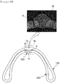
FIG. 7A is a perspective view of a torsion beam applied to a method of manufacturing a torsion beam according to an exemplary embodiment of the present disclosure, as viewed from above. -
FIG. 7B is a perspective view of a torsion beam applied to a method of manufacturing a torsion beam according to an exemplary embodiment of the present disclosure, as viewed from below. -
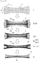
FIGS. 8A and9A are views illustrating a case in which a method of manufacturing a torsion beam according to an exemplary embodiment of the present disclosure, having a protruding portion formed on an upper mold of the present disclosure, is applied. -
FIGS. 8B and9B are diagrams illustrating a case of application of a method of manufacturing a torsion beam in a case in which a protruding portion is not formed on the upper mold, as compared with the present disclosure. - Hereinafter, exemplary embodiments of the present disclosure will be described with reference to the accompanying drawings. However, embodiments of the present disclosure may be modified in various other forms, and the scope of the present disclosure is not limited to the embodiments described below. In addition, embodiments of the present disclosure are provided to more completely describe the present disclosure to those with average knowledge in the art. In the drawings, the shapes and sizes of elements may be exaggerated for clearer explanation.
- Hereinafter, a method of manufacturing a torsion beam according to an exemplary embodiment of the present disclosure will be described in detail with reference to
FIGS. 1 to 9B . - A method of manufacturing a torsion beam according to an exemplary embodiment of the present disclosure may include a blank preparation operation ((S1)), an indented groove forming operation (S2), a rolling-up operation (S3), a flattening operation (S4), a welding joining operation (S5), and a quenching operation (S7), and may additionally include a protruding line forming operation (S6) and a tempering operation S8.
- Referring to
FIGS. 1 to 9B , the method of manufacturing a torsion beam may include the blank preparation operation (S1) of preparing a blank S obtained by processing a plate material, the indented groove forming operation (S2) of pressing the blank S with alower mold 30 to form an indentedgroove portion 200 of atorsion beam 10, a rolling-up operation (S3) of rolling up so that both edges of the blank S oppose each other in a width direction D2, a flattening operation (S4) in which a protrudingportion 21 of anupper mold 20 presses both edges of the blank S in the width direction D2 to be plastically deformed to be flat, in a state in which both edges of the blank S in the width direction D2 are supported to oppose each other byside cams 40, the welding joining operation (S5) of welding and joining the flattened both edges of the blank S in the width direction D2, and a quenching operation (S7) of heating the welded and joined whole blank S at a temperature ranging from 900 to 970 degrees (°C), forming a holding time in the range of 1 to 20 minutes, and cooling the blank S in a treatment liquid containing at least one of oil and water in the range of 20 to 90 degrees (°C). - Referring to
FIG. 1 , the method of manufacturing a torsion beam according to an exemplary embodiment includes the quenching operation (S7) after the welding and joining operation, to heat treat the entire blank S, thereby preventing a softening phenomenon that may occur in a welded portion after welding in high-strength steel or the like. In addition, since the strength of the welded portion may have the same characteristics as the strength of a base metal portion other than the welded portion, there is an effect of improving the durability of the welded portion. - In this manner, the reason why the entire welded blank S is heated in the range of 900 to 970 degrees °C is that there is a problem, in which if the heating temperature is lower than 900 degrees in the quenching operation (S7), austenite is not generated, and if the heating temperature is higher than 970 degrees, the austenite crystal becomes coarse to reduce the final strength.
- For example, the treatment liquid used in the quenching operation (S7) may be composed of 15 to 25% of oil by weight, and the rest: water and unavoidably-included impurities.
- Referring to
FIG. 1 , the method of manufacturing a torsion beam may include, after the quenching operation (S7), a tempering operation (S8) of heating the entire blank S having been subjected to the quenching operation (S7) to 150 to 600 degrees (°C) to form a holding time in the range of 10 to 120 minutes, and cooling the blank S in air. - In the tempering operation S8, to remove residual stress and induce recrystallization in the blank S that has undergone through the quenching operation (S7), a relatively long temperature holding time should be formed at a relatively low temperature, compared to the quenching operation (S7).
- In this manner, the reason for heating the entire blank S to which the quenching operation (S7) was applied, at a temperature ranging from 150 to 600 degrees °C, in the tempering operation (S8), is that if a heating temperature in the quenching operation (S7) is lower than 150 degrees °C, the effect of tempering decreases, and if the heating temperature is higher than 600 degrees °C, the martensite fraction may be too low, resulting in a problem in which the strength may decrease.
- In addition, the reason for maintaining the holding time in the range of 10 to 120 minutes for the entire blank to which the quenching operation (S7) was applied, in the tempering operation S8, is that if the holding time in the tempering operation (S8) is less than 10 minutes, there is no effect of tempering and thus brittleness may be maintained high, and if the holding time in the tempering operation (S8) exceeds 120 minutes, the effect of the quenching operation (S7) may be lost.
- In more detail, the blank S, which has undergone the quenching operation (S7), is heated to 200 to 550 degrees °C to form a holding time in the range of 10 to 120 minutes, and may be cooled in air.
- For example, in the case of the blank S that has undergone up to the welding joining operation (S5), before the quenching operation (S7) and the tempering operation S8, the yield strength is 992 to 444 unit: MPa, and the tensile strength is 620 to 696 Unit: MPa, and the elongation unit: % is 22 to 25%.
- As described above, the case of prior to the quenching operation (S7) and the tempering operation S8 is a state in which elongation is sufficiently secured, but the yield strength and tensile strength are significantly low, and thus, the method of manufacturing a torsion beam according to an exemplary embodiment of the present disclosure may include the quenching operation (S7) and the tempering operation S8.
- In the quenching operation (S7), the entire blank S was heated at 900 degrees °C for 7 minutes, and 80% of water and 20% of oil in weight percent were applied as a treatment liquid in performing the quenching operation (S7), and as a result, the yield strength was 1186 MPa, the tensile strength was 1951 MPa, and the elongation was 6.6%.
- In this case, the tensile strength was very high, but the ductility was insufficient, and thus, by heating at 200 degrees for 30 minutes in the next operation, the tempering operation, the yield strength was 1466 MPa, the tensile strength was 1830 MPa, and the elongation of 10.4% could be obtained.
- As described above, it can be seen that the method of manufacturing a torsion beam according to an exemplary embodiment of the present disclosure further includes the quenching operation (S7) and the tempering operation S8, thereby generating a martensite structure to significantly improve yield strength and tensile strength, while securing sufficient elongation, and thus suppressing brittleness.
[Table 1] * Treatment liquid: 80% of water + 20% of oil Heat treatment process Conditions Yield Strength MPa Tensile Strength MPa Elongation% As received 392 - 444 620 - 696 22 - 25 Quenching Operation 900 °C, hold for 7 minutes 1186 1951 6.6 Tempering Operation 200 °C, hold for 30 minutes 1466 1830 10.4 - Referring to
FIGS. 2 and3 , the blank preparation operation (S1) is an operation of preparing a blank S manufactured in a set shape by processing a plate material. - In the blank preparation operation (S1), the blank S having a set shape may be manufactured by cutting the plate material.
- As an example, the blank S having a set shape may be prepared by cutting a plate material formed of a metal plate such as steel or the like.
- As an example, the blank S may be comprised of a steel plate having a tensile strength of 780 MPa or more.
- In more detail, the blank S may be formed of a steel plate having a tensile strength of 980 MPa or more.
- Referring to
FIGS. 2 and4 , in the indented groove forming operation (S2), theindented groove portion 200 of thetorsion beam 10 may be formed by pressing the blank S with thelower mold 30. - In the indented groove forming operation (S2), the
indented groove portion 200 of thetorsion beam 10 may be formed by pressing the blank S with thelower mold 30 to deform the lower surface of the blank S upwardly. - Referring to
FIG. 4 , the inflow of the blank S may be controlled with theupper mold 20 and aholder 70, and theindented groove portion 200 may be formed in thetorsion beam 10 by pressing the blank S with thelower mold 30 in a state in which the blank S is disposed between theupper mold 20 and thelower mold 30. - In this case, a plurality of
guides 60 may be disposed to penetrate through theupper mold 20 and theholder 70. - Referring to
FIGS. 2 ,5 and 6 , in the rolling-up operation (S3), edge portions of the blank S in the width direction D2 may be rolled up to oppose each other. - In the rolling-up operation (S3), the edge portions of the blank S in the width direction D2 may be rolled up in the protruding direction of a
protruding line 300. - In the rolling-up operation (S3), the edge portions of the blank S in the width direction D2 of the blank S may be rolled up by the
lower mold 30 or theside cam 40, to be opposed to each other. - Referring to
FIGS. 5 and 6 , the rolling-up operation (S3) may include a U-shaped processing operation (S3)-1 of fixing the components with theupper mold 20 and apad 80, pushing the blank S into thelower mold 30, and rolling up the blank S to have a 'U'-shaped cross-section, and an O-shaped processing operation (S3)-2 of rolling up so that both edges of the blank S in the width direction D2 are rolled-up to a weldable position to be opposed to each other, to have an 'O'-shaped cross-section. - The
torsion beam 10 may be processed to have an 'O'-shaped cross-sectional shape by theside cams 40 disposed on both side surfaces thereof. - When processing into an 'O'-shaped cross-sectional shape by the
side cams 40, thetorsion beam 10 should not be in contact with the protrudingportion 21 of theupper mold 20. - This is to prevent the
protrusion portion 21 of theupper mold 20 from being caught in a welded joint W of the blank S and thus causing unwanted deformation, when processed into an 'O'-shaped cross-sectional shape by theside cams 40. - For example, in the state in which the protruding
portion 21 of theupper mold 20 is disposed between both edges of the blank S in the width direction D2, when the blank S is processed to have an 'O'-shaped cross-sectional shape by theside cams 40, deformation may occur in which the gap between both edges of the blank S in the width direction D2 is excessively widened by the protrudingportion 21 of theupper mold 20. - Thereafter, when the
torsion beam 10 is processed into an 'O'-shaped cross-sectional shape by theside cams 40 disposed on both sides, fine adjustments may be performed to fit the final shape of thetorsion beam 10, while adjusting theupper mold 20, thelower mold 30, and theside cam 40. - Referring to
FIG. 6 , in the rolling-up operation (S3), edge portions of the blank S in the width direction D2 of the blank S may be rolled up in the inward direction of theprotruding line 300 in a state in which fixedmolds 50 are disposed in both end regions of the blank S in a length direction D1. - By disposing the fixed
molds 50 in the both end regions of the blank S in the length direction D1, end portions of abeam body 100 may be produced to have a shape for coupling trailing arms. - Referring to
FIG. 2 , in the flattening operation (S4), in a state in which the edge portions of the blank S in the width direction D2 are supported by theside cams 40 to be opposed to each other, the protrudingportion 21 of theupper mold 20 presses the edge portions of the blank S in the width direction D2 to be plastically deformed flat. - Referring to
FIGS. 8A and9A , in the flattening operation (S4), the matching surface of the blank S may be horizontally processed in the state in which both edge portions of the blank S in the width direction D2 oppose each other. - For example, the upper surface and the lower surface may be processed horizontally while both edge regions of the blank S in the width direction D2 are opposed to each other.
- For example, in the flattening operation (S4), in a state in which edge portions of the blank S in the width direction D2 are opposed, the matching surface of the blank S may be flattening processed to be in the range of an inclination angle of -3.5 degrees to +3.5 degrees in a horizontal state.
- As an example, in a state in which both edge portions of the blank S in the width direction D2 contacting each other, the opposed matching surfaces of the blank S may be flatly processed.
- At least in a state in which edge portions of the blank S in the width direction D2 are adjacent, the
upper mold 20 may press adjacent edge portions of the blank S to form the matching surfaces in parallel. - In this case, the edge portions of the blank S in the width direction D2, which have been disposed adjacently by the pressure of the
upper mold 20, may be in contact with each other. - As another example, in the flattening operation (S4), the opposed matching surfaces of the blank S may be processed to be flat in a state in which the edge portions of the blank S in the width direction D2 contacting each other.
- In the flattening operation (S4), in a state in which edge portions of the blank S in the width direction D2 are in contact, the
upper mold 20 may press the edge portions of the blank S in contact with each other to form the matching surfaces in parallel. - Referring to
FIGS. 8A and9A , in the flattening operation (S4), plastic deformation may be formed in a state in which the protrudingportion 21 of theupper mold 20 is disposed in a position corresponding to theprotruding line 300 of the blank S. - In the case of
FIGS. 8A and9A , a method of manufacturing a torsion beam according to an exemplary embodiment, in which the protrudingportion 21 is formed on theupper mold 20, is applied. - In the case of
FIGS. 8B and9B , a method of manufacturing a torsion beam, in a case in which the protrudingportion 21 is not formed on theupper mold 20, as compared with the present disclosure, is applied. - Referring to
FIGS. 8A and9A , in the method of manufacturing thetorsion beam 10 according to an exemplary embodiment of the present disclosure, theprotrusion portion 21 of theupper mold 20 presses the matching surfaces of the blank S to induce plastic deformation thereof, thereby reducing the force that the blank (S) undergone the rolling-up operation (S3) is to be elastically restored. - Accordingly, while a flat surface T1 is formed to enable the matching surface to be flat, the shape precision of the welded joint W is secured to secure the integrity of the welded joint W to improve the durability of the welded joint W.
- Referring to
FIGS. 8A and9A , unlike the present disclosure, in a case in which the protrudingportion 21 is not formed on theupper mold 20, it can be seen that the matching surface is not flattened, and the matching surface has a curved surface (T2) having a considerable inclination angle in a horizontal state, and cracks (X) occurs in the welded joint (W), thereby deteriorating durability performance. - The size of the protruding
portion 21 formed on theupper mold 20, applied in the flattening operation (S4), may be equal to or relatively smaller than the size of theprotruding line 300. - As an example, the size of the protruding
portion 21 formed on theupper mold 20, applied to the flattening operation (S4), may be equal to the size of theprotruding line 300. - As another example, the size of the protruding
portion 21 formed on theupper mold 20, applied to the flattening operation (S4), may be relatively smaller than the size of theprotruding line 300. - Referring to
FIG. 2 , in the welding joining operation (S5), the edge portions of the flattened blank S in the width direction D2 may be welded and joined together. - Referring to
Figure 2 , the method of manufacturing a torsion beam, prior to the flattening operation, may include the protruding line forming operation (S6) of forming theprotruding line 300 in a direction opposite to the inward direction of theindented groove portion 200 by pressing the blank S with theupper mold 20 on which the protrudingportion 21 is formed. - Referring to
FIGS. 2 and4 , in the operation of forming a protruding line (S6), prior to the flattening operation (S4), the blank S is pressed with theupper mold 20 in which the protrudingpart 21 is formed, and the indented groove portion theprotruding line 300 may be formed in a direction opposite to the inward direction of 200. - As an example, the protruding line forming operation (S6) may be performed between the indented groove forming operation (S2) and the rolling-up operation (S3).
- As another example, after the protruding line forming operation (S6), the indented groove forming operation (S2) may be performed.
- As an example, a method of manufacturing a torsion beam may be performed in the order of the blank preparation operation (S1), the indented groove forming operation (S2), the protruding line forming operation (S6), the rolling-up operation (S3), the flattening operation (S4), and the welding joining operation (S5).
- In another example, a method of manufacturing a torsion beam may be performed in the order of a blank preparation operation (S1), a protruding line forming operation (S6), an indented groove forming operation (S2), a rolling-up operation (S3), a flattening operation (S4), and a welding joining operation (S5).
- The method of manufacturing a torsion beam according to an exemplary embodiment of the present disclosure is exemplified as a preferred manufacturing method in order to enable a person having ordinary knowledge in the technical field of the present disclosure to easily implement the present disclosure. Modifications may be carried out in a different order or other ancillary processes may be added.
- In addition, it will be apparent that various embodiments of the
torsion beam 10 having various embodiments to be described later may be applied to the method of manufacturing a torsion beam according to an exemplary embodiment. - Referring to
FIGS. 7A and7B , thetorsion beam 10 may include abeam body 100 extending in the length direction D1 and having a cross-section in the width direction D2, which forms a closed cross-section, anindented groove portion 200 inwardly indented in thebeam body 100 in the length direction D1, and aprotruding line 300 protruding from theindented groove portion 200 in an outward direction of the closed cross-section and extending in the length direction D1. - The
torsion beam 10 is disposed in the width direction of the vehicle, and trailing arms may be joined to end portions of thetorsion beam 10. - The
torsion beam 10 according to an exemplary embodiment of the present disclosure may be formed of steel having a tensile strength of 780 MPa or more. - In more detail, the
torsion beam 10 according to an exemplary embodiment may be formed of steel having a tensile strength of 980 MPa or more. - The
beam body 100 may extend in the length direction D1, and the cross-section in the width direction D2 may form a closed cross section. - The
beam body 100 has an effect of increasing the cross-sectional rigidity of thetorsion beam 10 by forming a closed cross-section. - The cross-section of the
beam body 100 is formed as a closed cross-section in which at least a portion of the inside is formed to have a hollow portion, and thus, has an effect of reducing the weight of thetorsion beam 10 while increasing the cross-sectional rigidity of thetorsion beam 10. - Trailing arms may be joined to both end portions of the
beam body 100 in the length direction D1. - As an example, the trailing arms may be welded to both ends of the
beam body 100 in the length direction D1. - As another example, the trailing arms may be fixed while the coupling members installed on the trailing arms are inserted into both end portions of the
beam body 100 in the length direction D1. - In the case of the
beam body 100, in a state in which edge portions of the blank S in the width direction D2 oppose each other, the edge portions of the blank S in the width direction D2 may be welded and joined in the state that the matching surface of the blank S is disposed horizontally. - In the case of the
beam body 100, in a state in which both edge portions of the blank S oppose each other in the width direction D2, the edge portions of the blank S in the width direction D2 may be welded and joined in a state in which the matching surface of the blank S is disposed to have an inclination angle ranging from -3.5 degrees to +3.5 degrees in a horizontal state. - In this case, when the matching surface has -3.5 degrees in a horizontal state, it indicates that both edge portions of the blank S in the width direction D2 are inclined downward by about 3.5 degrees.
- In addition, when the matching surface has +3.5 degrees in a horizontal state, it indicates that edge portions of the blank S in the width direction D2 are inclined upward by about 3.5 degrees.
- The
indented groove portion 200 is formed to be inwardly inserted in thebeam body 100, and theindented groove portion 200 may be formed in the length direction D1 of thebeam body 100. - The
indented groove portion 200 may be indentedly formed in a 'V' shape in thebeam body 100 or may be indented in a curved 'U' shape in thebeam body 100. - The protruding
line 300 may protrude from theindented groove portion 200 toward the outside of the closed cross-section of thebeam body 100. - The protruding
line 300 may form a plurality of inflection points R together with theindented groove portion 200, thereby increasing cross-sectional rigidity of thetorsion beam 10. - In this case, the
indented groove portion 200 forms at least 9 inflection points R on theindented groove portion 200 in a state inserted in the inward direction of the closed cross-section of thebeam body 100, while the protrudingline 300 protrudes in a direction from theindented groove portion 200 to the outside of the closed cross-section of thebeam body 100, thereby increasing the cross-sectional rigidity of thetorsion beam 10. - Referring to
FIGS. 8A and9A , the protrudingline 300 may be formed to have a 'U' shape by protruding in a direction from theindented groove portion 200 to the outside of the closed cross-section of thebeam body 100. - In this case, the protruding
line 300 may have a 'U'-shaped open portion disposed in the inner direction of the closed cross-section of thebeam body 100. - Although not illustrated, the protruding
line 300 may be formed to protrude in a 'V' shape from theindented groove portion 200 toward the outside of the closed cross-section of thebeam body 100. - In this case, the protruding
line 300 may have a 'V'-shaped open portion disposed in the inner direction of the closed cross-section of thebeam body 100. - When the
protruding line 300 protrudes in a 'U' shape or protrudes in a 'V' shape, the protrudingline 300 may form three inflection points R together with theindented groove portion 200. - Although not illustrated, the protruding
line 300 may be formed to protrude in a '⊏' shape from theindented groove portion 200 toward the outside of the closed cross-section of thebeam body 100. - In this case, the protruding
line 300 may have an open portion of a '⊏' shape in the inner direction of the closed cross-section of thebeam body 100. - When the
protruding line 300 is formed to protrude in a '□' shape, the protrudingline 300 may form four inflection points R together with theindented groove portion 200. - Referring to
FIGS. 7 and9A , the protrudingline 300 may be formed to protrude from agroove center 210 of theindented groove portion 200 toward the outside of the closed cross-section. - The protruding
line 300 may be formed in the length direction D1 along thegroove center 210 of theindented groove portion 200. - In this case, while being formed in the length direction D1 along the
groove center 210 of theindented groove portion 200, the protrudingline 300 may be formed over at least 60% or more of the total length of thegroove center 210 of theindented groove portion 200. - As an example, the protruding
line 300 may be formed over the entirety of thegroove center 210 formed in the length direction D1 of the intendedgroove portion 200. - As an example, referring to
FIGS. 7 , the protrudingline 300 may be formed over the entirety of thegroove center 210 in the length direction D1, formed in the length direction D1 of theindented groove portion 200, and over end inclinedpoints 230 of both sides of theindented groove portion 200, in which an upward slope is formed from the end of thegroove center 210. - In detail, the
indented groove portion 200 is configured with thegroove center 210 corresponding to the low point of theindented groove portion 200 and extending in the length direction D1, and the end inclinedpoints 230 forming inclined surfaces upwardly from ends of both sides of thegroove center 210. - Stress tends to be concentrated at the boundary between the
groove center 210 and the end inclined points 230. - In the present disclosure, by forming the
protruding line 300 over thegroove center 210 of theindented groove portion 200 and over the end inclinedpoints 230 on both sides, there is an effect of improving the durability against stress concentration by reinforcing the boundary between thegroove center 210 and the end inclinedpoints 230 by the protrudingline 300. - Although the embodiments of the present disclosure have been described in detail above, the scope of the present disclosure is not limited thereto, and various modifications and variations are possible without departing from the technical spirit of the present disclosure described in the claims, which will be obvious to those of ordinary skill in the art.
Description of Reference Numerals 10: torsion beam 20: upper mold 21: protruding portion 30: lower mold 40: side cam 50: fixed mold 60: guide 70: holder 80: pad 100: beam body 200:indented groove portion 210: groove center 230: end inclined point 300: protruding line D1: length direction D2: width direction R: inflection point S: blank S1: blank preparation operation S2: indented groove forming operation S3:rolling-up operation S3-1: U-type processing operation S3-2: O-type processing operation S4: flattening operation S5:welding joining operation S6: protruding line forming operation S7: quenching operation S8: tempering operation T1: flat surface T2: curved surface W: welded joint X: cracks
Claims (10)
- A method of manufacturing a torsion beam, comprising:preparing a blank obtained by processing a plate material;forming an indented groove portion of the torsion beam by pressing the blank with a lower mold;rolling up the blank in such a manner that edge portions of the blank in a width direction oppose each other;a flattening operation of flattening the edge portions of the blank to be plastically deformed, by pressing the edge portions of the blank in the width direction with a protruding portion of an upper mold, in a state in which the edge portions of the blank in the width direction are supported to oppose each other by side cams;welding and joining the edge portions of the blank in the width direction, flattened in the flattening operation; anda quenching operation of heating an entirety of the welded and joined blank at a temperature ranging from 900 to 970°C for a retaining time within a range of 1 to 20 minutes and cooling the blank in a treatment liquid including at least one of oil and water in a range of 20 to 90°C.
- The method of manufacturing a torsion beam of claim 1, wherein after the quenching operation, the method comprises a tempering operation of heating the entirety of the blank subjected to the quenching operation to 150 to 600 degrees (°C) for a holding time in a range of 10 to 120 minutes, and cooling the blank in air.
- The method of manufacturing a torsion beam of claim 1, wherein prior to the flattening operation, the method comprises forming a protruding line in a direction opposite to an inward direction of the indented groove portion by pressing the blank with an upper mold having a protruding portion formed thereon.
- The method of manufacturing a torsion beam of claim 1, wherein the flattening operation is performed by horizontally processing a matching surface of the blank, in a state in which the edge portions of the blank in the width direction oppose each other.
- The method of manufacturing a torsion beam of claim 1, wherein the flattening operation is performed by flattening such that a matching surface of the blank has an inclination angle ranging from -3.5 degrees to +3.5 degrees in a horizontal state, in a state in which the edge portions of the blank in the width direction oppose each other.
- The method of manufacturing a torsion beam of claim 1, wherein the flattening operation is performed to plastically deform the blank in a state in which the protruding portion of the upper mold is located in a position corresponding to a protruding line of the blank.
- The method of manufacturing a torsion beam of claim 1, wherein a size of the protruding portion formed on the upper mold is equal to or relatively smaller than a size of a protruding line of the blank.
- The method of manufacturing a torsion beam of claim 1, wherein the rolling up the blank comprises:a U-shape processing operation of fixing the blank with the upper mold and a pad, pushing the blank into the lower mold and rolling up the blank in such a manner that the blank has a 'U'-shaped cross-section; andan O-shape processing operation of rolling up the blank up to a weldable position such that the edge portions of the blank in the width direction oppose each other and thus, the blank has an 'O'-shaped cross-section.
- The method of manufacturing a torsion beam of claim 1, wherein the rolling up the blank is performed, by rolling up the edge portions of the blank in the width direction, in an inward direction of the protruding line, in a state in which a fixed mold is disposed in both end regions of the blank in a length direction.
- The method of manufacturing a torsion beam of any one of claims 1 to 9, wherein the torsion beam comprises:a beam body extending in a length direction, and having a cross-section in a width direction, forming a closed cross section;an indented groove portion formed to be inwardly indented in the length direction in the beam body; anda protruding line protruding from the indented groove portion toward an outside of the closed cross-section and extending in the length direction.
Applications Claiming Priority (2)
| Application Number | Priority Date | Filing Date | Title |
|---|---|---|---|
| KR1020180152529A KR102245234B1 (en) | 2018-11-30 | 2018-11-30 | Manuacturing method for torsion beam |
| PCT/KR2019/016284 WO2020111697A1 (en) | 2018-11-30 | 2019-11-25 | Method for manuacturing torsion beam |
Publications (2)
| Publication Number | Publication Date |
|---|---|
| EP3888842A1 true EP3888842A1 (en) | 2021-10-06 |
| EP3888842A4 EP3888842A4 (en) | 2022-01-26 |
Family
ID=70851859
Family Applications (1)
| Application Number | Title | Priority Date | Filing Date |
|---|---|---|---|
| EP19889930.4A Pending EP3888842A4 (en) | 2018-11-30 | 2019-11-25 | Method for manuacturing torsion beam |
Country Status (5)
| Country | Link |
|---|---|
| US (1) | US12036600B2 (en) |
| EP (1) | EP3888842A4 (en) |
| KR (1) | KR102245234B1 (en) |
| CN (1) | CN113165125B (en) |
| WO (1) | WO2020111697A1 (en) |
Families Citing this family (4)
| Publication number | Priority date | Publication date | Assignee | Title |
|---|---|---|---|---|
| CN111822635B (en) * | 2020-07-08 | 2022-03-04 | 贵州航天新力科技有限公司 | Progressive forming process and forming equipment for U-shaped forged piece |
| CN111822638B (en) * | 2020-07-08 | 2022-06-03 | 贵州航天新力科技有限公司 | Forging piece forming die and assembling method thereof |
| CN114131294A (en) * | 2021-11-26 | 2022-03-04 | 四川建安工业有限责任公司 | Method for manufacturing rear torsion beam suspension |
| KR102799519B1 (en) * | 2022-06-30 | 2025-04-23 | 현대제철 주식회사 | Method of manufacturing a torsion beam for a vehicle suspension and vehicle suspension |
Family Cites Families (31)
| Publication number | Priority date | Publication date | Assignee | Title |
|---|---|---|---|---|
| KR970008526U (en) | 1995-08-29 | 1997-03-27 | Automotive torsion beam structure advantageous for package | |
| DE19941993C1 (en) * | 1999-09-02 | 2000-12-14 | Benteler Werke Ag | Tubular profile manufacturing method for passenger vehicle rear axle uses cold-forming of central part of round cross-section steel tube before localised heating and hardening in water |
| CN100469482C (en) * | 2000-02-04 | 2009-03-18 | 株式会社理光 | Pipe, pipe making method and equipment |
| DE10139661C1 (en) * | 2001-08-11 | 2003-02-13 | Linde & Pullman Ag Zuerich | Sheet metal profile carrier for automobile body component has each arm of profile cross-section provided with double layers bonded together by adhesive |
| JP4211722B2 (en) | 2004-10-07 | 2009-01-21 | トヨタ自動車株式会社 | Torsion beam suspension system |
| KR20070014326A (en) | 2005-07-28 | 2007-02-01 | 현대자동차주식회사 | Torsion beam of CTBA suspension |
| JP2007069674A (en) | 2005-09-05 | 2007-03-22 | Futaba Industrial Co Ltd | Torsion beam type suspension and its manufacturing method |
| KR100907225B1 (en) * | 2007-05-23 | 2009-07-10 | 주식회사화신 | Hot forming apparatus and hot forming method |
| KR100958977B1 (en) | 2007-07-25 | 2010-05-20 | 주식회사 포스코 | Tubular torsion beam for rear wheel suspension of automobile and manufacturing method thereof |
| KR100935018B1 (en) * | 2008-07-09 | 2010-01-06 | 주식회사화신 | Beam formed by plank and making method thereof |
| KR101122957B1 (en) * | 2009-08-11 | 2012-03-15 | (주) 디에이치홀딩스 | Suspension torsion beam manufacturing process line apparatus and hybrid press forming torsion beam thereof |
| JP5779875B2 (en) | 2010-12-21 | 2015-09-16 | Jfeスチール株式会社 | Manufacturing method of torsion beam |
| KR20110118607A (en) | 2011-10-07 | 2011-10-31 | 정우창 | Steel pipes for automobile parts and manufacturing method thereof |
| KR101304752B1 (en) | 2011-12-28 | 2013-09-05 | 주식회사 포스코 | Torsion Beam Producing Method |
| RU2014149563A (en) * | 2012-06-15 | 2016-08-10 | Магна Интернэшнл Инк. | ADJUSTABLE STAMP FOR FORMING TURNING BEAMS FROM PIPES |
| CN102756177B (en) * | 2012-07-08 | 2015-12-16 | 黑旋风锯业股份有限公司 | A kind of manufacture method of compound noise-reduction diamond saw blade matrix |
| KR101420009B1 (en) | 2012-08-24 | 2014-07-15 | 주식회사 동희산업 | Method of manufacturing coupled torsion beam typed suspension in vehicle |
| WO2014147827A1 (en) | 2013-03-22 | 2014-09-25 | 株式会社ヨロズ | Torsion beam suspension device |
| WO2014172437A1 (en) * | 2013-04-16 | 2014-10-23 | Magna International Inc. | Twist beam with joined inner and outer parts |
| DE102014109680A1 (en) | 2014-07-10 | 2016-01-14 | Benteler Automobiltechnik Gmbh | Method for producing a torsion profile from a board and torsion profile |
| DE112015004708T5 (en) * | 2014-10-14 | 2017-07-13 | Magna International Inc. | VEHICLE-beam axle ARRANGEMENT |
| KR101666951B1 (en) | 2014-12-22 | 2016-10-18 | (주)동희산업 | Apparatus for manufacturing torsion beam |
| KR101657834B1 (en) | 2014-12-24 | 2016-09-20 | 주식회사 포스코 | Manufacturing method for torsion beam having ultra high strength |
| KR101665819B1 (en) | 2014-12-24 | 2016-10-13 | 주식회사 포스코 | Steel material for heat treating, formed component having extra high strength and high fatigue resistance and method for manufacturing the formed component |
| DE102015114943B8 (en) | 2015-09-07 | 2025-09-11 | Benteler Automobiltechnik Gmbh | Method for producing a closed hollow profile for a vehicle axle |
| KR101724026B1 (en) | 2015-10-15 | 2017-04-19 | 주식회사 디케이오스텍 | Tubular beam of a torsion beam axle manufacturing method |
| CN106282520B (en) | 2016-08-03 | 2018-07-10 | 浙江玛斯特汽配有限公司 | A kind of torsion-bar spring thermomechanical treatment process |
| KR101805604B1 (en) | 2017-03-06 | 2017-12-06 | 주식회사 체시스 | A method of manufacturing an arm and a trailing arm and a torsion beam |
| JP2018176240A (en) * | 2017-04-17 | 2018-11-15 | 本田技研工業株式会社 | Method of manufacturing a torsion beam |
| JP7034468B2 (en) | 2017-12-12 | 2022-03-14 | 株式会社ワイテック | Pipe making equipment |
| CN108467921B (en) | 2018-04-12 | 2019-08-23 | 湖北三江航天江北机械工程有限公司 | Double medium timesharing quenching heat treatment methods |
-
2018
- 2018-11-30 KR KR1020180152529A patent/KR102245234B1/en active Active
-
2019
- 2019-11-25 US US17/298,131 patent/US12036600B2/en active Active
- 2019-11-25 WO PCT/KR2019/016284 patent/WO2020111697A1/en not_active Ceased
- 2019-11-25 EP EP19889930.4A patent/EP3888842A4/en active Pending
- 2019-11-25 CN CN201980078796.3A patent/CN113165125B/en active Active
Also Published As
| Publication number | Publication date |
|---|---|
| WO2020111697A1 (en) | 2020-06-04 |
| CN113165125B (en) | 2024-02-13 |
| EP3888842A4 (en) | 2022-01-26 |
| KR102245234B1 (en) | 2021-04-29 |
| CN113165125A (en) | 2021-07-23 |
| US20220016684A1 (en) | 2022-01-20 |
| US12036600B2 (en) | 2024-07-16 |
| KR20200066448A (en) | 2020-06-10 |
Similar Documents
| Publication | Publication Date | Title |
|---|---|---|
| US12036600B2 (en) | Method for manufacturing torsion beam | |
| US9039073B2 (en) | Method of manufacturing vehicle body side structure and vehicle body side structure | |
| US20160362139A1 (en) | Vehicle body side frame | |
| US11945053B2 (en) | Tailored blank, tailored blank manufacturing method, stamped part, and stamped part manufacturing method | |
| US7117708B2 (en) | Die set for press forming metal sheet and press forming method of metal sheet | |
| US20160067814A1 (en) | Spot welding method | |
| US10160495B2 (en) | Vehicle body structure | |
| US20230148259A1 (en) | Hot-stamped part and method of manufacturing the same | |
| US20140223743A1 (en) | Method for producing a motor vehicle stabilizer | |
| CN107662647A (en) | Method for the column of motor vehicle and for manufacturing column | |
| KR102604480B1 (en) | Blanks and structural members | |
| KR20160061560A (en) | Method for tailor welded blanks | |
| KR101639905B1 (en) | Welding member having excellent welded portion fatigue characteristic and method for manufacturing the same | |
| US20120023748A1 (en) | Method of making a shaped metal part for a motor vehicle component | |
| US20200079435A1 (en) | Suspension support bracket and method for manufacturing suspension support bracket | |
| US10898942B2 (en) | Method for the production of a closed hollow profile for a vehicle axle | |
| JP2001123227A (en) | Method of manufacturing flexible and torsion-resistant tubular profiles as cross-beams for pivot beam rear axles in passenger cars | |
| US12042840B2 (en) | Hot press processing method and processing device | |
| US12269532B2 (en) | Forming sheet metal part for a vehicle frame and corresponding production method | |
| CN113439001A (en) | Method for manufacturing steel rail and steel rail | |
| CN114524023A (en) | Vehicle body structure and automobile | |
| KR20120132836A (en) | Hot stamping molding product and method of manufacturing the same | |
| JP6127669B2 (en) | Manufacturing method of hot stamping molded product and manufacturing method of blank material | |
| US20200188980A1 (en) | Steel sheet member and method for producing the same | |
| KR101185319B1 (en) | Method of manufacturing low arm using laser surface heat treatment |
Legal Events
| Date | Code | Title | Description |
|---|---|---|---|
| STAA | Information on the status of an ep patent application or granted ep patent |
Free format text: STATUS: THE INTERNATIONAL PUBLICATION HAS BEEN MADE |
|
| PUAI | Public reference made under article 153(3) epc to a published international application that has entered the european phase |
Free format text: ORIGINAL CODE: 0009012 |
|
| STAA | Information on the status of an ep patent application or granted ep patent |
Free format text: STATUS: REQUEST FOR EXAMINATION WAS MADE |
|
| 17P | Request for examination filed |
Effective date: 20210607 |
|
| AK | Designated contracting states |
Kind code of ref document: A1 Designated state(s): AL AT BE BG CH CY CZ DE DK EE ES FI FR GB GR HR HU IE IS IT LI LT LU LV MC MK MT NL NO PL PT RO RS SE SI SK SM TR |
|
| A4 | Supplementary search report drawn up and despatched |
Effective date: 20220104 |
|
| RIC1 | Information provided on ipc code assigned before grant |
Ipc: B23K 103/04 20060101ALN20211221BHEP Ipc: B23K 101/18 20060101ALN20211221BHEP Ipc: B23K 101/06 20060101ALN20211221BHEP Ipc: B23K 101/00 20060101ALN20211221BHEP Ipc: B60G 21/05 20060101ALI20211221BHEP Ipc: B21D 53/88 20060101ALI20211221BHEP Ipc: B21D 35/00 20060101ALI20211221BHEP Ipc: B21D 5/10 20060101ALI20211221BHEP Ipc: B21D 22/02 20060101ALI20211221BHEP Ipc: B60G 11/18 20060101ALI20211221BHEP Ipc: C21D 9/50 20060101ALI20211221BHEP Ipc: C21D 1/78 20060101ALI20211221BHEP Ipc: B23K 31/02 20060101ALI20211221BHEP Ipc: B23P 17/00 20060101ALI20211221BHEP Ipc: B23P 15/00 20060101AFI20211221BHEP |
|
| DAV | Request for validation of the european patent (deleted) | ||
| DAX | Request for extension of the european patent (deleted) | ||
| RAP3 | Party data changed (applicant data changed or rights of an application transferred) |
Owner name: AUSTEM CO. LTD. Owner name: POSCO HOLDINGS INC. |
|
| RAP1 | Party data changed (applicant data changed or rights of an application transferred) |
Owner name: AUSTEM CO. LTD. Owner name: POSCO CO., LTD |