EP3888578A1 - Plate bender for mandibular implants and bending process - Google Patents
Plate bender for mandibular implants and bending process Download PDFInfo
- Publication number
- EP3888578A1 EP3888578A1 EP20000232.7A EP20000232A EP3888578A1 EP 3888578 A1 EP3888578 A1 EP 3888578A1 EP 20000232 A EP20000232 A EP 20000232A EP 3888578 A1 EP3888578 A1 EP 3888578A1
- Authority
- EP
- European Patent Office
- Prior art keywords
- mandibular
- plate
- bending
- implants according
- plate bender
- Prior art date
- Legal status (The legal status is an assumption and is not a legal conclusion. Google has not performed a legal analysis and makes no representation as to the accuracy of the status listed.)
- Granted
Links
Images


Classifications
-
- A—HUMAN NECESSITIES
- A61—MEDICAL OR VETERINARY SCIENCE; HYGIENE
- A61B—DIAGNOSIS; SURGERY; IDENTIFICATION
- A61B17/00—Surgical instruments, devices or methods
- A61B17/56—Surgical instruments or methods for treatment of bones or joints; Devices specially adapted therefor
- A61B17/58—Surgical instruments or methods for treatment of bones or joints; Devices specially adapted therefor for osteosynthesis, e.g. bone plates, screws or setting implements
- A61B17/88—Osteosynthesis instruments; Methods or means for implanting or extracting internal or external fixation devices
- A61B17/8863—Apparatus for shaping or cutting osteosynthesis equipment by medical personnel
-
- A—HUMAN NECESSITIES
- A61—MEDICAL OR VETERINARY SCIENCE; HYGIENE
- A61F—FILTERS IMPLANTABLE INTO BLOOD VESSELS; PROSTHESES; DEVICES PROVIDING PATENCY TO, OR PREVENTING COLLAPSING OF, TUBULAR STRUCTURES OF THE BODY, e.g. STENTS; ORTHOPAEDIC, NURSING OR CONTRACEPTIVE DEVICES; FOMENTATION; TREATMENT OR PROTECTION OF EYES OR EARS; BANDAGES, DRESSINGS OR ABSORBENT PADS; FIRST-AID KITS
- A61F2/00—Filters implantable into blood vessels; Prostheses, i.e. artificial substitutes or replacements for parts of the body; Appliances for connecting them with the body; Devices providing patency to, or preventing collapsing of, tubular structures of the body, e.g. stents
- A61F2/02—Prostheses implantable into the body
- A61F2/30—Joints
- A61F2/3094—Designing or manufacturing processes
- A61F2/30942—Designing or manufacturing processes for designing or making customized prostheses, e.g. using templates, CT or NMR scans, finite-element analysis or CAD-CAM techniques
-
- B—PERFORMING OPERATIONS; TRANSPORTING
- B21—MECHANICAL METAL-WORKING WITHOUT ESSENTIALLY REMOVING MATERIAL; PUNCHING METAL
- B21D—WORKING OR PROCESSING OF SHEET METAL OR METAL TUBES, RODS OR PROFILES WITHOUT ESSENTIALLY REMOVING MATERIAL; PUNCHING METAL
- B21D7/00—Bending rods, profiles, or tubes
-
- B—PERFORMING OPERATIONS; TRANSPORTING
- B21—MECHANICAL METAL-WORKING WITHOUT ESSENTIALLY REMOVING MATERIAL; PUNCHING METAL
- B21D—WORKING OR PROCESSING OF SHEET METAL OR METAL TUBES, RODS OR PROFILES WITHOUT ESSENTIALLY REMOVING MATERIAL; PUNCHING METAL
- B21D7/00—Bending rods, profiles, or tubes
- B21D7/12—Bending rods, profiles, or tubes with program control
-
- A—HUMAN NECESSITIES
- A61—MEDICAL OR VETERINARY SCIENCE; HYGIENE
- A61B—DIAGNOSIS; SURGERY; IDENTIFICATION
- A61B17/00—Surgical instruments, devices or methods
- A61B17/56—Surgical instruments or methods for treatment of bones or joints; Devices specially adapted therefor
- A61B17/58—Surgical instruments or methods for treatment of bones or joints; Devices specially adapted therefor for osteosynthesis, e.g. bone plates, screws or setting implements
- A61B17/68—Internal fixation devices, including fasteners and spinal fixators, even if a part thereof projects from the skin
- A61B17/80—Cortical plates, i.e. bone plates; Instruments for holding or positioning cortical plates, or for compressing bones attached to cortical plates
- A61B17/8061—Cortical plates, i.e. bone plates; Instruments for holding or positioning cortical plates, or for compressing bones attached to cortical plates specially adapted for particular bones
- A61B17/8071—Cortical plates, i.e. bone plates; Instruments for holding or positioning cortical plates, or for compressing bones attached to cortical plates specially adapted for particular bones for the jaw
-
- A—HUMAN NECESSITIES
- A61—MEDICAL OR VETERINARY SCIENCE; HYGIENE
- A61F—FILTERS IMPLANTABLE INTO BLOOD VESSELS; PROSTHESES; DEVICES PROVIDING PATENCY TO, OR PREVENTING COLLAPSING OF, TUBULAR STRUCTURES OF THE BODY, e.g. STENTS; ORTHOPAEDIC, NURSING OR CONTRACEPTIVE DEVICES; FOMENTATION; TREATMENT OR PROTECTION OF EYES OR EARS; BANDAGES, DRESSINGS OR ABSORBENT PADS; FIRST-AID KITS
- A61F2/00—Filters implantable into blood vessels; Prostheses, i.e. artificial substitutes or replacements for parts of the body; Appliances for connecting them with the body; Devices providing patency to, or preventing collapsing of, tubular structures of the body, e.g. stents
- A61F2/02—Prostheses implantable into the body
- A61F2/28—Bones
- A61F2/2803—Bones for mandibular reconstruction
Definitions
- the present invention relates to the field of biomedical engineering, particularly it relates to a plate bender for mandibular implants and the process employing it, which is intended for improving the bending process of mandibular plates or implants, reducing the number of folds (bents) until obtaining the desired geometry, further reducing fatigues failures, costs and streamlining the process, by providing a high-precision, semiautomatic bender, with modular and transportable assembly.
- the system may comprise a plate member defining a plurality of openings to receive fasteners that attach the plate member to the bone.
- the plate member may include a pair of undercut flanges formed by opposite edge regions of the plate member.
- the system also may comprise a bending tool configured to be operatively associated with the plate member after the plate member is attached to bone, with a region of the bending tool positioned under each of the undercut flanges, such that rotation of the bending tool applies a moment to the plate member.
- the invention defined in this anteriority features the disadvantage that the plate bending is performed manually, on the bone, without including any element which guarantees a final bending angle.
- each bender includes a lever arm having a first end and a second end.
- the first end includes a fulcrum for placement on the upper surface of the plate, and a foot insertable through the oblong screw hole to contact the lower surface of the plate.
- the second end includes a cut-out with a central divider.
- the cut-out has a length dimensioned to extend widthwise about the plate at the location of the oblong screw hole with the divider extending into the oblong screw hole for stability.
- the second end may also be provided with a deep slot that accommodates the thickness of the plate.
- plate benders with such structure can be used in pairs to longitudinal bend the plate; bend the plate in plane; or twist the plate along its axis.
- the invention defined in this anteriority features the disadvantage that the plate bending is performed manually, and does not include any element which guarantees a final bending angle either.
- document US6423068 can also be found, which refers to an apparatus for osteosynthesis of a mandible, wherein the apparatus contains an elongated plate having a plurality of apertures, and the plate has a first portion, a second portion, and a central portion intermediate the first and second portions. Each of the apertures within the first portion and within the second portion are disposed in relatively close spaced relationship. The width of the plate between apertures is less in the central portion than in the first portion, and it can be bent to a relatively small radius in the central portion without distorting the apertures within the central portion.
- the invention also refers to a method for surgically preparing a mandible, which in its steps includes bending the plate to substantially conform to the mandible such that the central portion thereof overlies the symphysis of the mandible.
- the anteriority does not specifically mention the way how the plate bending is carried out, but it just limits to indicate that, in a step of the method, the plate is bent.
- document RU2692982 which relates to a procedure for maxillofacial surgery, wherein said surgical procedure is performed through a bone graft using surgical templates with guide channels for drilling a series of screw holes, wherein the method comprises making a stereolithography model, bending reconstructive plate, manufacturing the model with transplant, attaching the bent plate to the stereolithographic model, determining the position of holes in in computer tomography (CT) with further reconstruction in a 3D program, transmitting data on the position of the screws on the plates, and finally placing the graft in the patient mandible.
- CT computer tomography
- said anteriority does not disclose all the characteristics of the invention since it just limits to indicated that in the surgical method one of the steps is bending the plate with the graft, but it does not specify the way how said bending is performed or the device or method used for carrying out the plate bending, which is the basis for the present development.
- one of the objectives of the present invention consists in providing an electronically assisted plate bender for performing punctual angulations and deformations on a mandibular plate, avoiding as much the human intervention and guaranteeing a high-quality standard.
- Another object of the present invention consists in providing a plate bender with modular and independent design which facilitates the assembly and disassembly process of subsystems and its respective component while being safe, simple and easy to transport.
- Another of the objects of the present invention consists in providing a feeding system having transmission by synchronic pulleys improving the advance of the mandibular plate and thus, the accuracy on the bending process, and a transmission system for the given movable by synchronic pulleys/time ratios 2:1, increasing the torque and reducing the speed allowing a greater accuracy and bending strength, with the aid of a bending die to improve the bending conditions of this kind of titanium plates.
- the present invention is directed to a plate bender for mandibular implants, comprising the following components: Plate bender for mandibular implants comprising a support structure (1), a feeding system (2), a clamping mechanism (22) which fastens the pate or mandibular implant in a specific position, a bending dice system (4), a power unit (5), a control unit (6), and an output platform.
- Said feeding system (2) comprises an advance mechanism by synchronic pulleys (21), operated by a feeding servo (24), a free roller mechanism (22) connected to a tensor mechanism (23) which improves the advancement and position of the mandibular plate and thus, the bending accuracy, wherein said elements are supported on the modular structure (11) of the feeding system.
- said bending dice system (4) comprises a fixed pin (42), a movable pin (41) of angular oscillation, wherein the movable pin receives the specific rotation power and angle by a power transmission system (52) formed by synchronic pulleys in transmission ratio 2:1, and a toothed belt (53), operated by the servo (51).
- control unit (6) comprises a mixed system formed by a touch controller (61) and auxiliary buttons (62) to facilitate its operation by the operator, wherein the electrical system (63) is located on one side of the support structure (1), side on which the 110V with integrated fuse charge or electrical power supply system (8) is located.
- the 48V 10Ah power source feeds the electronic circuitry and the control system.
- Said support structure (1) is configured on a modular manner to facilitate the maintenance of each of the elements and comprises the modular structure (11) of the feeding system, the modular structure (12) of the power system, the transportation handles (7), and the covers (13), (14), which are easy to remove for maintenance, its attachment could be made through screws, allowing that both the electrical and mechanical reparations can be performed with minimal disassembly.
- the feed from the platform to the fastening and bending mechanism can be mechanical or automatic.
- the present invention also comprises a method for bending mandibular implants, characterized by comprising the following steps:
- Said method is further characterized in that the bending step is automatic, reducing the number of folds and increasing the accuracy of the bent product.
- the plate or mandibular implant feeding and positioning process can be made mechanically or automatically.
Landscapes
- Health & Medical Sciences (AREA)
- Orthopedic Medicine & Surgery (AREA)
- Life Sciences & Earth Sciences (AREA)
- Engineering & Computer Science (AREA)
- Surgery (AREA)
- Animal Behavior & Ethology (AREA)
- Veterinary Medicine (AREA)
- Public Health (AREA)
- Biomedical Technology (AREA)
- Heart & Thoracic Surgery (AREA)
- General Health & Medical Sciences (AREA)
- Molecular Biology (AREA)
- Medical Informatics (AREA)
- Nuclear Medicine, Radiotherapy & Molecular Imaging (AREA)
- Cardiology (AREA)
- Vascular Medicine (AREA)
- Transplantation (AREA)
- Oral & Maxillofacial Surgery (AREA)
- Mechanical Engineering (AREA)
- Neurology (AREA)
- Plastic & Reconstructive Surgery (AREA)
- Physics & Mathematics (AREA)
- Geometry (AREA)
- Manufacturing & Machinery (AREA)
- Surgical Instruments (AREA)
- Prostheses (AREA)
Abstract
Description
- The present invention relates to the field of biomedical engineering, particularly it relates to a plate bender for mandibular implants and the process employing it, which is intended for improving the bending process of mandibular plates or implants, reducing the number of folds (bents) until obtaining the desired geometry, further reducing fatigues failures, costs and streamlining the process, by providing a high-precision, semiautomatic bender, with modular and transportable assembly.
- In treating mandibular fractures, it is common the use of plates for fixating the portions of fractured bone, this is how said plates should be bent by surgeons at the moment of intervention, in order to achieve a proper fit to the patient bone. However, said bending process usually subjects the plate to more than one fold in the bending (folding) points, causing thereby loss of the mechanic properties of the plate due to fatigue.
- In addition, the time invested and the bending process during surgery propitiate possible infections in the patient and delays in surgeries.
- There is a plurality of disclosures in the state of the art which propose different solutions to the technical problem indicated, such as document
US9918762B2 - However, the invention defined in this anteriority features the disadvantage that the plate bending is performed manually, on the bone, without including any element which guarantees a final bending angle.
- On the other hand, document
US8419745B2 discloses a pair of plate benders for bending a bone plate. Each bender includes a lever arm having a first end and a second end. The first end includes a fulcrum for placement on the upper surface of the plate, and a foot insertable through the oblong screw hole to contact the lower surface of the plate. The second end includes a cut-out with a central divider. The cut-out has a length dimensioned to extend widthwise about the plate at the location of the oblong screw hole with the divider extending into the oblong screw hole for stability. The second end may also be provided with a deep slot that accommodates the thickness of the plate. In use, plate benders with such structure can be used in pairs to longitudinal bend the plate; bend the plate in plane; or twist the plate along its axis. - However, the invention defined in this anteriority features the disadvantage that the plate bending is performed manually, and does not include any element which guarantees a final bending angle either.
- In the state of the art, document
US6423068 can also be found, which refers to an apparatus for osteosynthesis of a mandible, wherein the apparatus contains an elongated plate having a plurality of apertures, and the plate has a first portion, a second portion, and a central portion intermediate the first and second portions. Each of the apertures within the first portion and within the second portion are disposed in relatively close spaced relationship. The width of the plate between apertures is less in the central portion than in the first portion, and it can be bent to a relatively small radius in the central portion without distorting the apertures within the central portion. The invention also refers to a method for surgically preparing a mandible, which in its steps includes bending the plate to substantially conform to the mandible such that the central portion thereof overlies the symphysis of the mandible. - However, the anteriority does not specifically mention the way how the plate bending is carried out, but it just limits to indicate that, in a step of the method, the plate is bent.
- On its part, document
RU2692982 - However, it should be noted that said anteriority does not disclose all the characteristics of the invention since it just limits to indicated that in the surgical method one of the steps is bending the plate with the graft, but it does not specify the way how said bending is performed or the device or method used for carrying out the plate bending, which is the basis for the present development.
- According to the above, it is clear that there is a need in the state of the art to design plate bender for mandibular implants which allows to obtain a plate bent customized to the patient, with the less number of operations necessary, in a precise and automatic manner, guaranteeing the desired output angles, avoiding fatigue failures and providing a final product with improved mechanical properties.
- Therefore, one of the objectives of the present invention consists in providing an electronically assisted plate bender for performing punctual angulations and deformations on a mandibular plate, avoiding as much the human intervention and guaranteeing a high-quality standard.
- Another object of the present invention consists in providing a plate bender with modular and independent design which facilitates the assembly and disassembly process of subsystems and its respective component while being safe, simple and easy to transport.
- Another of the objects of the present invention consists in providing a feeding system having transmission by synchronic pulleys improving the advance of the mandibular plate and thus, the accuracy on the bending process, and a transmission system for the given movable by synchronic pulleys/time ratios 2:1, increasing the torque and reducing the speed allowing a greater accuracy and bending strength, with the aid of a bending die to improve the bending conditions of this kind of titanium plates.
- The present invention can be more clearly understood from the following figures where the components and results associated to the present element are shown, as well as the novel characteristics relative to the state of the art, wherein the figures do not intend to limit the scope of the invention, which is only provided by the appended claims, where:
-
Figure 1 corresponds to a perspective view of the plate bender in its application position, from two different angles. -
Figure 2 corresponds to a view of the plate bender, without the top cover, which allows to observe the arrangement of elements inside the bender. -
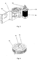
Figure 3 shows the power unit subassembly, the bending mechanical system (bending dice) and its components. -
Figure 4 shows in detail one of the synchronic pulleys and the bending dice. -
Figure 5 shows the feeding system, the tensor and the free rollers. -
Figure 6 shows the control unit, the electronic system and the electrical power supply system. - The present invention is directed to a plate bender for mandibular implants, comprising the following components:
Plate bender for mandibular implants comprising a support structure (1), a feeding system (2), a clamping mechanism (22) which fastens the pate or mandibular implant in a specific position, a bending dice system (4), a power unit (5), a control unit (6), and an output platform. - Said feeding system (2) comprises an advance mechanism by synchronic pulleys (21), operated by a feeding servo (24), a free roller mechanism (22) connected to a tensor mechanism (23) which improves the advancement and position of the mandibular plate and thus, the bending accuracy, wherein said elements are supported on the modular structure (11) of the feeding system.
- In addition, said bending dice system (4) comprises a fixed pin (42), a movable pin (41) of angular oscillation, wherein the movable pin receives the specific rotation power and angle by a power transmission system (52) formed by synchronic pulleys in transmission ratio 2:1, and a toothed belt (53), operated by the servo (51).
- On its part, the control unit (6) comprises a mixed system formed by a touch controller (61) and auxiliary buttons (62) to facilitate its operation by the operator, wherein the electrical system (63) is located on one side of the support structure (1), side on which the 110V with integrated fuse charge or electrical power supply system (8) is located. On its part, the 48V 10Ah power source feeds the electronic circuitry and the control system.
- Said support structure (1) is configured on a modular manner to facilitate the maintenance of each of the elements and comprises the modular structure (11) of the feeding system, the modular structure (12) of the power system, the transportation handles (7), and the covers (13), (14), which are easy to remove for maintenance, its attachment could be made through screws, allowing that both the electrical and mechanical reparations can be performed with minimal disassembly.
- The feed from the platform to the fastening and bending mechanism can be mechanical or automatic.
- Finally, the present invention also comprises a method for bending mandibular implants, characterized by comprising the following steps:
- Entering plate bending position and angle data, according to the virtual surgical planning data.
- Positioning the mandibular implant on the feeding platform, mechanically or automatically.
- Starting the bending the process by activating the plate bender for mandibular implants, and
- Removing the bent piece.
- Said method is further characterized in that the bending step is automatic, reducing the number of folds and increasing the accuracy of the bent product.
- On its part, the plate or mandibular implant feeding and positioning process can be made mechanically or automatically.
- Although the above description defines the preferred embodiments of the present invention, said invention is not limited thereto, but, instead, it also intends to include in the scope of the application all the variations or modifications which are evident for those skilled in the art and which do not affect and modify the spirit of the invention.
Claims (16)
- Plate bender for mandibular implants characterized by comprising a support structure (1), a feeding system (2), a fastening mechanism (22) supporting the plate or mandibular implant in a specific position, a bending dice system (4), a power unit (5), a control unit (6), and an output platform.
- The plate bender for mandibular implants according to claim 1, characterized in that the feeding system (2) comprises an advance mechanism by synchronic pulleys (21), operated by a feeding servo (24), a free roller mechanism (22) connected to a tensor mechanism (23) controlling advancement of the mandibular plate and bending accuracy, wherein said elements are supported on a modular structure (11) of the feeding system.
- The plate bender for mandibular implants according to claim 1, characterized in that the bending dice system (4) comprises a fixed pin (42), a movable pin (41) of angular oscillation.
- The plate bender for mandibular implants according to claim 1, characterized in that the power unit (5) comprises a servo (51), a power transmission system (52), wherein said elements are supported on a modular structure (12) of the power unit.
- The plate bender for mandibular implants according to the preceding claims, characterized in that the power transmission system (52) comprises synchronic pulleys and a toothed belt (53).
- The plate bender for mandibular implants according to the preceding claims, characterized in that the power transmission unit (52) has a ratio of 2:1.
- The plate bender for mandibular implants according to claim 1, characterized in that the control unit (6) comprises a touch controller (61) and auxiliary buttons (62).
- The plate bender for mandibular implants according to claim 1, characterized in that the support structure (1) has transportation handles (7).
- The plate bender for mandibular implants according to claim 1, characterized in that it has an electrical charge or power supply system (8).
- The plate bender for mandibular implants according to claim 1, characterized in that the support structure (1) comprises covers (13, 14) for modular maintenance.
- The plate bender for mandibular implants according to any preceding claim, characterized in that the feeding from the platform to the fastening and bending mechanism is mechanic.
- The plate bender for mandibular implants according to claims 1 to 10, characterized in that the feeding from the platform to the fastening and bending mechanism is automatic.
- Method for bending mandibular implants, characterized by comprising the following steps:• Entering plate bending position and angle data, according to virtual surgical planning data;• Positioning the mandibular implant on the feeding platform, mechanically or automatically;• Starting the bending the process by activating the plate bender for mandibular implants; and• Removing the bent piece.
- The method for bending mandibular implants according to claim 13, characterized in that the step of bending is automatic.
- The method for bending mandibular implants according to claims 13 and 14, characterized in that the plate or mandibular implant feeding and positioning process is automatic.
- The method for bending mandibular implants according to claims 13 and 14, characterized in that the plate or mandibular implant feeding and positioning process is mechanic.
Applications Claiming Priority (1)
| Application Number | Priority Date | Filing Date | Title |
|---|---|---|---|
| CONC2020/0003890A CO2020003890A1 (en) | 2020-03-30 | 2020-03-30 | Mandibular implant plate bender and bending process |
Publications (3)
| Publication Number | Publication Date |
|---|---|
| EP3888578A1 true EP3888578A1 (en) | 2021-10-06 |
| EP3888578B1 EP3888578B1 (en) | 2024-12-18 |
| EP3888578C0 EP3888578C0 (en) | 2024-12-18 |
Family
ID=75293623
Family Applications (1)
| Application Number | Title | Priority Date | Filing Date |
|---|---|---|---|
| EP20000232.7A Active EP3888578B1 (en) | 2020-03-30 | 2020-06-29 | Plate bender for mandibular implants |
Country Status (4)
| Country | Link |
|---|---|
| US (1) | US11653964B2 (en) |
| EP (1) | EP3888578B1 (en) |
| CO (1) | CO2020003890A1 (en) |
| ES (1) | ES3004571T3 (en) |
Citations (8)
| Publication number | Priority date | Publication date | Assignee | Title |
|---|---|---|---|---|
| US6423068B1 (en) | 2000-10-18 | 2002-07-23 | Erhard Reisberg | Method and apparatus for mandibular osteosynthesis |
| US20050262911A1 (en) * | 2004-02-06 | 2005-12-01 | Harry Dankowicz | Computer-aided three-dimensional bending of spinal rod implants, other surgical implants and other articles, systems for three-dimensional shaping, and apparatuses therefor |
| US20070227216A1 (en) * | 2006-02-16 | 2007-10-04 | Nabil Muhanna | Automated pedicle screw rod bender |
| US8419745B2 (en) | 2010-04-23 | 2013-04-16 | Biomet C.V. | Bone plate bender system |
| US9918762B2 (en) | 2015-04-23 | 2018-03-20 | Acumed Llc | System for deforming plate members on bone |
| RU2692982C1 (en) | 2018-02-08 | 2019-06-28 | Сергей Васильевич Терещук | Method of mandibular defect elimination surgery with bone graft |
| US10524846B2 (en) * | 2017-04-05 | 2020-01-07 | Warsaw Orthopedic, Inc. | Surgical implant bending system and method |
| US20200015858A1 (en) * | 2017-11-09 | 2020-01-16 | Globus Medical, Inc. | Robotic rod benders and related mechanical and motor housings |
Family Cites Families (2)
| Publication number | Priority date | Publication date | Assignee | Title |
|---|---|---|---|---|
| US10405908B2 (en) * | 2014-12-18 | 2019-09-10 | Warsaw Orthopedic, Inc. | Apparatus and method for forming support device for effecting orthopedic stabilization |
| US11975380B2 (en) * | 2018-11-09 | 2024-05-07 | Brochman Innovations, Llc | Tubing bender |
-
2020
- 2020-03-30 CO CONC2020/0003890A patent/CO2020003890A1/en unknown
- 2020-06-29 EP EP20000232.7A patent/EP3888578B1/en active Active
- 2020-06-29 ES ES20000232T patent/ES3004571T3/en active Active
- 2020-06-30 US US16/916,192 patent/US11653964B2/en active Active
Patent Citations (8)
| Publication number | Priority date | Publication date | Assignee | Title |
|---|---|---|---|---|
| US6423068B1 (en) | 2000-10-18 | 2002-07-23 | Erhard Reisberg | Method and apparatus for mandibular osteosynthesis |
| US20050262911A1 (en) * | 2004-02-06 | 2005-12-01 | Harry Dankowicz | Computer-aided three-dimensional bending of spinal rod implants, other surgical implants and other articles, systems for three-dimensional shaping, and apparatuses therefor |
| US20070227216A1 (en) * | 2006-02-16 | 2007-10-04 | Nabil Muhanna | Automated pedicle screw rod bender |
| US8419745B2 (en) | 2010-04-23 | 2013-04-16 | Biomet C.V. | Bone plate bender system |
| US9918762B2 (en) | 2015-04-23 | 2018-03-20 | Acumed Llc | System for deforming plate members on bone |
| US10524846B2 (en) * | 2017-04-05 | 2020-01-07 | Warsaw Orthopedic, Inc. | Surgical implant bending system and method |
| US20200015858A1 (en) * | 2017-11-09 | 2020-01-16 | Globus Medical, Inc. | Robotic rod benders and related mechanical and motor housings |
| RU2692982C1 (en) | 2018-02-08 | 2019-06-28 | Сергей Васильевич Терещук | Method of mandibular defect elimination surgery with bone graft |
Also Published As
| Publication number | Publication date |
|---|---|
| US20210298809A1 (en) | 2021-09-30 |
| CO2020003890A1 (en) | 2021-04-08 |
| EP3888578B1 (en) | 2024-12-18 |
| US11653964B2 (en) | 2023-05-23 |
| ES3004571T3 (en) | 2025-03-12 |
| EP3888578C0 (en) | 2024-12-18 |
Similar Documents
| Publication | Publication Date | Title |
|---|---|---|
| US20240189886A1 (en) | Systems, devices, and methods for designing and forming a surgical implant | |
| KR101710932B1 (en) | System and method for designing and forming a surgical implant | |
| US20050262911A1 (en) | Computer-aided three-dimensional bending of spinal rod implants, other surgical implants and other articles, systems for three-dimensional shaping, and apparatuses therefor | |
| EP2266492A2 (en) | Method and apparatus for forming a custom orthodontic appliance | |
| EP3888578B1 (en) | Plate bender for mandibular implants | |
| WO2001034044A9 (en) | Bone distractor having a positioning device | |
| CN109394328A (en) | The 3D printing of fibular flap transplanting mandibular defect is assisted to preset screw way and the embedded guide plate system of titanium plate | |
| EP4066763A2 (en) | Installation for forming osteosynthesis plates | |
| CN112790825A (en) | Osteotomy Guide | |
| EP4051145A1 (en) | Orthognathic surgical implant assembly having pre-osteotomy and post-osteotomy alignment members | |
| CN211583438U (en) | Intraoperative spine connecting rod customizing device and system | |
| RU2829203C1 (en) | Method and device for bending personalized implants from reconstructive titanium plates | |
| CN115886966A (en) | Continuous funnel chest orthopedic system | |
| CN111195145B (en) | A closed osteotomy guide device | |
| CN117084750B (en) | Osteotomy correction auxiliary device | |
| US20250025185A1 (en) | Surgical Tools and Procedures for Tibial Plateau Leveling Osteotomy | |
| CN214806454U (en) | Leg support frame of bending for gynecological examination | |
| WO2020044128A1 (en) | Rigid surgical stent | |
| CN220714010U (en) | Reset fixing clamp with automatic positioning function | |
| US20260014711A1 (en) | Automated robotic rod bender | |
| CN120585446A (en) | Automatic titanium rod bending device and bending method for spinal deformity surgery | |
| WO2025119444A1 (en) | Rod bending robot | |
| KR20180093286A (en) | Bending machine for Titanium hollow bar used in Intramedullary nail | |
| CN111195146A (en) | A multi-angle closed osteotomy guiding device with indication function | |
| WO2025259953A1 (en) | Biplanar adjustable bone reduction plate with wedge window |
Legal Events
| Date | Code | Title | Description |
|---|---|---|---|
| PUAI | Public reference made under article 153(3) epc to a published international application that has entered the european phase |
Free format text: ORIGINAL CODE: 0009012 |
|
| STAA | Information on the status of an ep patent application or granted ep patent |
Free format text: STATUS: THE APPLICATION HAS BEEN PUBLISHED |
|
| AK | Designated contracting states |
Kind code of ref document: A1 Designated state(s): AL AT BE BG CH CY CZ DE DK EE ES FI FR GB GR HR HU IE IS IT LI LT LU LV MC MK MT NL NO PL PT RO RS SE SI SK SM TR |
|
| STAA | Information on the status of an ep patent application or granted ep patent |
Free format text: STATUS: REQUEST FOR EXAMINATION WAS MADE |
|
| 17P | Request for examination filed |
Effective date: 20220112 |
|
| GRAP | Despatch of communication of intention to grant a patent |
Free format text: ORIGINAL CODE: EPIDOSNIGR1 |
|
| STAA | Information on the status of an ep patent application or granted ep patent |
Free format text: STATUS: GRANT OF PATENT IS INTENDED |
|
| RIC1 | Information provided on ipc code assigned before grant |
Ipc: A61B 17/80 20060101ALN20240828BHEP Ipc: A61F 2/28 20060101ALN20240828BHEP Ipc: B21D 7/12 20060101ALN20240828BHEP Ipc: B21D 7/00 20060101ALN20240828BHEP Ipc: A61F 2/30 20060101ALI20240828BHEP Ipc: A61B 17/88 20060101AFI20240828BHEP |
|
| INTG | Intention to grant announced |
Effective date: 20240919 |
|
| GRAS | Grant fee paid |
Free format text: ORIGINAL CODE: EPIDOSNIGR3 |
|
| GRAA | (expected) grant |
Free format text: ORIGINAL CODE: 0009210 |
|
| STAA | Information on the status of an ep patent application or granted ep patent |
Free format text: STATUS: THE PATENT HAS BEEN GRANTED |
|
| AK | Designated contracting states |
Kind code of ref document: B1 Designated state(s): AL AT BE BG CH CY CZ DE DK EE ES FI FR GB GR HR HU IE IS IT LI LT LU LV MC MK MT NL NO PL PT RO RS SE SI SK SM TR |
|
| REG | Reference to a national code |
Ref country code: CH Ref legal event code: EP |
|
| REG | Reference to a national code |
Ref country code: DE Ref legal event code: R096 Ref document number: 602020043208 Country of ref document: DE |
|
| REG | Reference to a national code |
Ref country code: IE Ref legal event code: FG4D |
|
| U01 | Request for unitary effect filed |
Effective date: 20250113 |
|
| U07 | Unitary effect registered |
Designated state(s): AT BE BG DE DK EE FI FR IT LT LU LV MT NL PT RO SE SI Effective date: 20250120 |
|
| REG | Reference to a national code |
Ref country code: ES Ref legal event code: FG2A Ref document number: 3004571 Country of ref document: ES Kind code of ref document: T3 Effective date: 20250312 |
|
| PG25 | Lapsed in a contracting state [announced via postgrant information from national office to epo] |
Ref country code: HR Free format text: LAPSE BECAUSE OF FAILURE TO SUBMIT A TRANSLATION OF THE DESCRIPTION OR TO PAY THE FEE WITHIN THE PRESCRIBED TIME-LIMIT Effective date: 20241218 |
|
| PG25 | Lapsed in a contracting state [announced via postgrant information from national office to epo] |
Ref country code: NO Free format text: LAPSE BECAUSE OF FAILURE TO SUBMIT A TRANSLATION OF THE DESCRIPTION OR TO PAY THE FEE WITHIN THE PRESCRIBED TIME-LIMIT Effective date: 20250318 |
|
| PG25 | Lapsed in a contracting state [announced via postgrant information from national office to epo] |
Ref country code: GR Free format text: LAPSE BECAUSE OF FAILURE TO SUBMIT A TRANSLATION OF THE DESCRIPTION OR TO PAY THE FEE WITHIN THE PRESCRIBED TIME-LIMIT Effective date: 20250319 |
|
| PG25 | Lapsed in a contracting state [announced via postgrant information from national office to epo] |
Ref country code: RS Free format text: LAPSE BECAUSE OF FAILURE TO SUBMIT A TRANSLATION OF THE DESCRIPTION OR TO PAY THE FEE WITHIN THE PRESCRIBED TIME-LIMIT Effective date: 20250318 |
|
| U20 | Renewal fee for the european patent with unitary effect paid |
Year of fee payment: 6 Effective date: 20250513 |
|
| PG25 | Lapsed in a contracting state [announced via postgrant information from national office to epo] |
Ref country code: SM Free format text: LAPSE BECAUSE OF FAILURE TO SUBMIT A TRANSLATION OF THE DESCRIPTION OR TO PAY THE FEE WITHIN THE PRESCRIBED TIME-LIMIT Effective date: 20241218 |
|
| PG25 | Lapsed in a contracting state [announced via postgrant information from national office to epo] |
Ref country code: PL Free format text: LAPSE BECAUSE OF FAILURE TO SUBMIT A TRANSLATION OF THE DESCRIPTION OR TO PAY THE FEE WITHIN THE PRESCRIBED TIME-LIMIT Effective date: 20241218 |
|
| PG25 | Lapsed in a contracting state [announced via postgrant information from national office to epo] |
Ref country code: IS Free format text: LAPSE BECAUSE OF FAILURE TO SUBMIT A TRANSLATION OF THE DESCRIPTION OR TO PAY THE FEE WITHIN THE PRESCRIBED TIME-LIMIT Effective date: 20250418 |
|
| PG25 | Lapsed in a contracting state [announced via postgrant information from national office to epo] |
Ref country code: SK Free format text: LAPSE BECAUSE OF FAILURE TO SUBMIT A TRANSLATION OF THE DESCRIPTION OR TO PAY THE FEE WITHIN THE PRESCRIBED TIME-LIMIT Effective date: 20241218 |
|
| PG25 | Lapsed in a contracting state [announced via postgrant information from national office to epo] |
Ref country code: CZ Free format text: LAPSE BECAUSE OF FAILURE TO SUBMIT A TRANSLATION OF THE DESCRIPTION OR TO PAY THE FEE WITHIN THE PRESCRIBED TIME-LIMIT Effective date: 20241218 |
|
| PGFP | Annual fee paid to national office [announced via postgrant information from national office to epo] |
Ref country code: ES Payment date: 20250702 Year of fee payment: 6 |
|
| PLBE | No opposition filed within time limit |
Free format text: ORIGINAL CODE: 0009261 |
|
| STAA | Information on the status of an ep patent application or granted ep patent |
Free format text: STATUS: NO OPPOSITION FILED WITHIN TIME LIMIT |
|
| REG | Reference to a national code |
Ref country code: CH Ref legal event code: L10 Free format text: ST27 STATUS EVENT CODE: U-0-0-L10-L00 (AS PROVIDED BY THE NATIONAL OFFICE) Effective date: 20251029 |
|
| 26N | No opposition filed |
Effective date: 20250919 |
|
| REG | Reference to a national code |
Ref country code: CH Ref legal event code: H13 Free format text: ST27 STATUS EVENT CODE: U-0-0-H10-H13 (AS PROVIDED BY THE NATIONAL OFFICE) Effective date: 20260127 |
|
| PG25 | Lapsed in a contracting state [announced via postgrant information from national office to epo] |
Ref country code: MC Free format text: LAPSE BECAUSE OF FAILURE TO SUBMIT A TRANSLATION OF THE DESCRIPTION OR TO PAY THE FEE WITHIN THE PRESCRIBED TIME-LIMIT Effective date: 20241218 |
|
| GBPC | Gb: european patent ceased through non-payment of renewal fee |
Effective date: 20250629 |
|
| PG25 | Lapsed in a contracting state [announced via postgrant information from national office to epo] |
Ref country code: GB Free format text: LAPSE BECAUSE OF NON-PAYMENT OF DUE FEES Effective date: 20250629 |
|
| PG25 | Lapsed in a contracting state [announced via postgrant information from national office to epo] |
Ref country code: IE Free format text: LAPSE BECAUSE OF NON-PAYMENT OF DUE FEES Effective date: 20250629 |
|
| PG25 | Lapsed in a contracting state [announced via postgrant information from national office to epo] |
Ref country code: CH Free format text: LAPSE BECAUSE OF NON-PAYMENT OF DUE FEES Effective date: 20250630 |