EP3888456A1 - Brdc sign detection system - Google Patents
Brdc sign detection system Download PDFInfo
- Publication number
- EP3888456A1 EP3888456A1 EP19891213.1A EP19891213A EP3888456A1 EP 3888456 A1 EP3888456 A1 EP 3888456A1 EP 19891213 A EP19891213 A EP 19891213A EP 3888456 A1 EP3888456 A1 EP 3888456A1
- Authority
- EP
- European Patent Office
- Prior art keywords
- data
- brdc
- bovine
- time period
- condition
- Prior art date
- Legal status (The legal status is an assumption and is not a legal conclusion. Google has not performed a legal analysis and makes no representation as to the accuracy of the status listed.)
- Withdrawn
Links
Images










Classifications
-
- A—HUMAN NECESSITIES
- A01—AGRICULTURE; FORESTRY; ANIMAL HUSBANDRY; HUNTING; TRAPPING; FISHING
- A01K—ANIMAL HUSBANDRY; AVICULTURE; APICULTURE; PISCICULTURE; FISHING; REARING OR BREEDING ANIMALS, NOT OTHERWISE PROVIDED FOR; NEW BREEDS OF ANIMALS
- A01K29/00—Other apparatus for animal husbandry
-
- G—PHYSICS
- G06—COMPUTING OR CALCULATING; COUNTING
- G06N—COMPUTING ARRANGEMENTS BASED ON SPECIFIC COMPUTATIONAL MODELS
- G06N20/00—Machine learning
-
- G—PHYSICS
- G06—COMPUTING OR CALCULATING; COUNTING
- G06Q—INFORMATION AND COMMUNICATION TECHNOLOGY [ICT] SPECIALLY ADAPTED FOR ADMINISTRATIVE, COMMERCIAL, FINANCIAL, MANAGERIAL OR SUPERVISORY PURPOSES; SYSTEMS OR METHODS SPECIALLY ADAPTED FOR ADMINISTRATIVE, COMMERCIAL, FINANCIAL, MANAGERIAL OR SUPERVISORY PURPOSES, NOT OTHERWISE PROVIDED FOR
- G06Q50/00—Information and communication technology [ICT] specially adapted for implementation of business processes of specific business sectors, e.g. utilities or tourism
- G06Q50/02—Agriculture; Fishing; Forestry; Mining
-
- A—HUMAN NECESSITIES
- A61—MEDICAL OR VETERINARY SCIENCE; HYGIENE
- A61B—DIAGNOSIS; SURGERY; IDENTIFICATION
- A61B7/00—Instruments for auscultation
- A61B7/003—Detecting lung or respiration noise
Definitions
- the present invention relates to a BRDC sign detecting system.
- a flow from breeding to sales in cattle is broadly divided into multiple processes (e.g. a grass feeding process, a fattening process, a processing process, and the like).
- a feedlot is within a certain area, there is a problem in that cattle can easily get infected with bovine respiratory disease complex (BRDC).
- BRDC bovine respiratory disease complex
- Non-Patent Document 1 proposes a system that automatically detects a bovine that has actually developed BRDC among bovines infected with BRDC.
- the system can identify a bovine that has developed BRDC earlier.
- Non-Patent Document 1 Cargill, "Cargill brings facial recognition capability to farmers through strategic equity investment in Cainthus", [online], 31 January 2018 [searched on 31 July 2018], Internet (URL:https://www.cargill.com/2018/cargill-brings-facial-recognition-capability-to-farmers )
- a BRDC sign detecting system includes an obtaining unit configured to obtain, with respect to a bovine developing bovine respiratory disease complex (BRDC) within a time period required for a fattening process, data indicating a condition of the bovine during a predetermined time period in which the bovine did not yet develop the BRDC, and obtain data indicating a condition, during a predetermined time period, of a bovine that has not developed BRDC as of an end of the time period required for the fattening process, a machine learning unit configured to perform machine learning with respect to a correspondence relation between the obtained data indicating the condition during the predetermined time period and information indicating whether BRDC is developed, and an inference unit configured to infer, by inputting data indicating a condition of a new bovine during the predetermined time period into a learned model generated by performing the machine learning with respect to the correspondence relation, information indicating whether the new bovine will develop BRDC and output an inference result.
- BRDC bovine developing bovine respiratory disease complex
- a BRDC sign detecting system that detects a sign of BRDC can be provided.
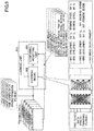
- FIG. 1 is a drawing illustrating an example of the system configuration of the BRDC sign detecting system.
- the BRDC sign detecting system 100 is a system that detects a sign of the BRDC development in each bovine within a feedlot 140 during the fattening process.
- the BRDC sign detecting system 100 includes a detecting device 110, a learning device 111, an imaging device group 130, a repeater 131 (and a sensor wirelessly connected to the repeater), a terminal device 150, and a terminal device 160.
- the detecting device 110 is communicatively connected to the imaging device group 130, the repeater 131, the terminal device 150, and the terminal device 160 through a network 120.
- the detecting device 110 receives image data captured by the imaging device group 130 and measurement data measured by sensors attached to a bovine through the repeater 131.
- the detecting device 110 detects a sign of the BRDC development in each bovine based on the received image data and the measured data (hereinafter referred to as feedlot data).
- the detecting device 110 determines a treatment to be administered to the bovine. As a result of the determination, if a medication treatment is to be taken to the bovine, a medication instruction is output to the terminal device 150. Additionally, as a result of the determination, if the bovine is to be given isolation treatment, an isolation instruction is output to the terminal device 160.
- the learning device 111 generates a learned model used when the detecting device 110 detects a sign of the BRDC development and provides the learned model to the detecting device 110.
- the learning device 111 collects captured image data and measured measurement data (hereinafter referred to as "experimental data") from the point of BRDC infection to the onset of BRDC symptoms for experimental bovines in an experimental field 112 and generates the learned model on which machine learning is performed.
- the learning device 111 modifies the generated learned model based on the feedlot data collected by the detecting device 110 with respect to the bovines in the feedlot 140.
- the imaging device group 130 is disposed around the feedlot 140 to capture images of the bovines in the feedlot 140.
- the imaging device group 130 transmits the captured image data to the detecting device 110 through the network 120.
- the repeater 131 receives measurement data measured by sensors attached to the bovines in the feedlot 140 through wireless communication and transmits the received measurement data to the detecting device 110 via the network 120.
- the terminal device 150 is a terminal carried by a fattener manager who manages each of the bovines in the feedlot 140 and notifies the fattener manager when the medication instruction is received from the detecting device 110. This enables the fattener manager to identify the bovine for which the medication instruction has been output and to administer medication.
- the terminal device 160 is a terminal carried by another fattener manager who manages each of the bovines in the feedlot 140 and notifies another fattener manager when the isolation instruction is output from the detecting device 110. This enables another fattener manager to identify the bovine for which the isolation instruction has been output and to transfer the bovine from the feedlot 140 to a sanatorium 182 to provide the isolation treatment.
- FIG. 1 also illustrates devices other than the BRDC sign detecting system 100 and the transfer of bovines other than the fattening process.
- a terminal device 181 transmits grazing data obtained by managing bovines grass-fed in a pasture 180 to the detecting device 110 through the network 120.
- Each of the bovines grass-fed at the pasture 180 is transferred to the feedlot 140 after the grass feeding process is completed and the fattening process is started in the feedlot 140.
- each of the bovines is checked and returned to the pasture 180 depending on a growth state.
- a bovine infected with BRDC or having developed BRDC is transferred to the sanatorium 182.
- each of the bovines for which the fattening process has been started in the feedlot 140 is transferred to an abattoir processor 183 when the fattening process is completed after a time period required for the fattening process (i.e., the time period required for fattening) has elapsed.
- a terminal device 184 manages each of the bovines for which the fattening process has been performed and that has been transferred to the abattoir processor 183. Specifically, the terminal device 184 collects data obtained during a time period in which each of the transferred bovines is processed and shipped by the abattoir processor 183, and transmits the data as process data to the detecting device 110.
- FIG. 2 illustrates the sensors attached to the bovine and the position where the sensors are attached.
- sensors having different sensor IDs for respective bovines are attached to the bovines in the feedlot 140.
- the sensors attached to each of the bovines include a group of multiple measurement elements, classified into the "acceleration,” the “temperature,” and the “sound” according to the measurement items.
- a measurement site is defined for each of the measurement items of the sensors attached to each of the bovines, and the measurement element is attached to each measurement site.
- the "acceleration” is measured at the “head” and “belly” of the bovine, and a “first acceleration sensor” and a “second acceleration sensor” are attached to the respective parts.
- the “temperature” is measured at the “neck” of the bovine and a “temperature sensor” is attached to the part.
- the “sound” is measured at the “belly” of the bovine and a “sound sensor” is attached to the part.
- a mounting fixture 201 is attached to the head of the bovine to perform various measurements at the head of the bovine.
- the "first acceleration sensor” is attached to the mounting fixture 201.
- the mounting fixture 202 is attached to the neck of the bovine to perform various measurements on the neck of the bovine.
- the "temperature sensor” is attached to the mounting fixture 202.
- the mounting fixture 203 is attached to the belly of the bovine to perform various measurements at the belly of the bovine.
- the "second acceleration sensor” and the "sound sensor” are attached.
- measurement data measured by the sensors is transmitted to the repeater 131 at a predetermined period in association with the sensor ID by a transmitter (which is not illustrated).
- the detecting device 110 can receive the measurement data (i.e., first acceleration data, second acceleration data, temperature data, and sound data) associated with the sensor ID at a predetermined period.
- FIG. 3 is a drawing illustrating an example layout of the imaging device group in the feedlot.
- the example of FIG. 3 indicates a state in which five imaging devices 310, 320, 330, 340, and 350 disposed around the feedlot 140 as the imaging device group 130.
- the imaging devices 310, 320, 330, 340, and 350 are installed on mounts 311, 321, 331, 341, and 351, respectively, and imaging ranges in a horizontal direction are defined so that an entire area within the feedlot 140 can be imaged. Imaging range in a height direction of the imaging devices 310, 320, 330, 340, and 350 are also defined so that an image of a standing state to an image of a lying state of the bovine can be taken.
- the imaging devices 310, 320, 330, 340, and 350 may all be visible light cameras that detect visible light, or some may be infrared cameras that detect infrared light. Additionally, the mounts 311, 321, 331, 341, and 351 may be fixed mounts or movable mounts (i.e., mounts that moves in pan, tilt, and roll directions).
- the detecting device 110 and the learning device 111 have substantially the same hardware configuration, and thus the hardware configuration of the detecting device 110 will be described here.
- FIG. 4 is a drawing illustrating an example of the hardware configuration of the detecting device.
- the detecting device 110 includes a central processing unit (CPU) 401, a read only memory (ROM) 402, and a random access memory (RAM) 403.
- the CPU 401, the ROM 402, and the RAM 403 form what is called a computer.
- the detecting device 110 also includes an auxiliary storage device 404, an operating device 405, a display device 406, a communication device 407, and a drive device 408.
- Each hardware component of the detecting device 110 is interconnected through a bus 409.
- the CPU 401 executes various programs installed in the auxiliary storage device 404 (e.g., a sign detection program which will be described later).
- the ROM 402 is a non-volatile memory and functions as a main storage device.
- the ROM 402 stores various programs, data, and the like required for the CPU 401 to execute various programs installed in the auxiliary storage device 404.
- the ROM 402 stores a boot program and the like, such as basic input/output system (BIOS) and extensible firmware interface (EFI).
- BIOS basic input/output system
- EFI extensible firmware interface
- the RAM 403 is a volatile memory, such as a dynamic random access memory (DRAM) or a static random access memory (SRAM), and functions as a main storage device.
- the RAM 403 provides a workspace where various programs installed in the auxiliary storage device 404 are deployed when the various programs are executed by the CPU 401.
- the auxiliary storage device 404 stores various programs, data collected by the CPU 401 executing various programs, data generated by processing the collected data, and the like.
- a sign detection data storage unit which will be described later, is implemented by the auxiliary storage device 404.
- the operating device 405 is an input device used when an administrator of the detecting device 110 inputs various instructions to the detecting device 110.
- the display device 406 is a display device that displays various information to the administrator of the detecting device 110.
- the communication device 407 is a communication device that connects to the network 120 and communicates with each device (i.e., the imaging device group 130, the repeater 131, the terminal device 150, the terminal device 160, the terminal device 181, the terminal device 184, or the like).
- the drive device 408 is a device for setting a recording medium 410.
- the recording medium 410 includes a medium that optically, electrically, or magnetically records information, such as a CD-ROM, a flexible disk, a magneto-optical disk, and the like. Additionally, the recording medium 410 may include a semiconductor memory or the like that electrically records information, such as a ROM, a flash memory, and the like.
- the various programs installed in the auxiliary storage device 404 are installed, for example, when the distributed recording medium 410 is set in the drive device 408 and the various programs recorded in the recording medium 410 are read by the drive device 408.
- the various programs installed on auxiliary storage device 404 may be installed by downloading through the network 120.
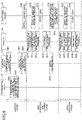
- FIG. 5 is a sequence diagram illustrating the flow of the entire process of the BRDC sign detecting system.
- the process of the BRDC sign detecting system 100 can be divided into a learning phase, a sign detection and learning phase, and a sign detection phase.
- the learning phase is a phase in which a learned model used by the detecting device 110 to detect a sign of the BRDC development is generated.
- the sign detection and learning phase is a phase in which the detecting device 110 detects a sign of the BRDC development using the learned model and modifies the learned model. Further, the detection phase is a phase in which the detecting device 110 detects a sign of the BRDC development by using the modified learned model.
- step S501 the learning device 111 starts to monitor the bovines in the experimental field 112 and collects experimental data.
- the learning device 111 can collect image data imaging the experimental bovine and measurement data measured by the sensors attached to the experimental bovine as the experimental data.
- step S502 an experimenter administers a virus or bacteria causing BRDC to each of the experimental bovines in the experimental field 112 and infects each of the experimental bovines with BRDC.
- step S503 the experimenter judges whether any experimental bovine has developed BRDC and whether any BRDC experimental bovine has become severe from among the experimental bovines infected with BRDC.
- the judgement of whether each of the experimental BRDC bovines has developed BRDC and whether each of the experimental bovine has become severe is performed based on, for example, whether a clinical score exceeds a predetermined threshold, with the experimenter judging daily clinical scores.
- BRDC bovine has become severe.
- the judged result of whether each of the experimental bovines has developed BRDC and the judged result of whether each of BRDC bovines has become severe are input into the learning device 111 in association with the experimental data.
- step S504 the learning device 111 generates training data (which will be described below in detail with reference to FIG. 8A and FIG. 8B ) by using the experimental data and the judged result, and performs an analysis.
- the learning device 111 for example, performs machine learning on the learning model by using the training data to analyze the training data.
- step S505 the learning device 111 generates a learned model by analyzing the training data.
- step S506 in the detecting device 110, the learned model generated by the learning device 111 is installed.
- the BRDC sign detecting system 100 transitions to the sign detection and learning phase.
- each of the bovines is first transferred from the pasture 180 to the feedlot 140.
- step S512 the fattener manager of the feedlot 140 checks a condition of each of the bovines transferred from the pasture 180.
- step S513 the detecting device 110 starts collecting feedlot data by starting to monitor each of the bovines in the feedlot 140.
- step S51 the fattener manager of the feedlot 140 starts the fattening process for each of the bovines whose conditions are well.
- step S515 the detecting device 110 uses the current feedlot data to detect a sign of the BRDC development for each of the bovines for which the fattening process has been started in the feedlot 140.
- step S5166 the fattener manager of the feedlot 140 performs the isolation treatment or the medication treatment on a bovine on which a sign of the BRDC development is detected.
- step S517 in the feedlot 140, the fattening process is terminated when the time required for the fattening process has elapsed.
- step S5108 the fattener manager of the feedlot 140 judges a condition of each of the bovines.
- the detecting device 110 generates training data (which will be described below in detail with reference to FIG. 12 ) by using results judged by the fattening manager of the feedlot 140 and sign detection data used to detect a sign (which will be described below in detail with reference to FIG. 10 ), and transmits the training data to the learning device 111.
- step S519 the learning device 111 again performs machine learning on the learning model by using the training data transmitted from the detecting device 110. This enables the learning device 111 to modify the learned model.
- step S520 in the detecting device 110, the learned model modified by the learning device 111 is installed. Upon completing the installation of the modified learned model, the BRDC sign detecting system 100 transitions to the sign detection phase.
- step S531 Upon moving to the sign detection phase, in step S531, next bovines are transferred from the pasture 180 to the feedlot 140.
- step S532 the fattener manager of the feedlot 140 checks a condition of each of the next bovines transferred from the pasture 180.
- step S533 the detecting device 110 starts to collect the feedlot data by starting to monitor each of the bovines on the feedlot 140.
- step S534 the fattener manager of the feedlot 140 starts the fattening process for each of the bovines whose conditions are well based on a result of the check.
- step S535 the detecting device 110 detects a sign of the BRDC development for each of the bovines for which the fattening process has been started in the feedlot 140 by using the sign detection data generated based on the current feedlot data.
- step S536 the fattener manager of the feedlot 140 performs the isolation treatment or the medication treatment on the bovine for which a sign of the BRDC development is detected.
- step S537 in the feedlot 140, the fattening process is terminated when the time required for the fattening process has elapsed.
- FIG. 6 is a first drawing illustrating an example of functional configurations of the learning device and the detecting device.
- a learning program is installed in the learning device 111 and, by executing the program, the learning device 111 functions as an experimental data collecting unit 610, an experimental data processing unit 611, a training data collecting unit 612, and a learning unit 613.
- the experimental data collecting unit 610 collects image data and measurement data transmitted from the experimental field 112 as experimental data. Additionally, the experimental data collecting unit 610 obtains a judged result of whether the experimental bovine has developed BRDC and a judged result of whether the experimental BRDC bovine has become severe (information indicating whether BRDC has been developed) in association with the experimental data.
- the experimental data processing unit 611 is an example of a processing unit, and extracts a feature from the collected experimental data and analyze the extracted feature to generate training data for each individual bovine.
- the training data collecting unit 612 is an example of an obtaining unit. In the learning phase, the training data collecting unit 612 stores training data (including corresponding judged results) generated in the experimental data processing unit 611, in the training data storage unit 614.
- the training data collecting unit 612 stores training data (including corresponding judged results) generated in the detecting device 110, in the training data storage unit 614.
- the learning unit 613 performs machine learning on the learning model by using, for example, the training data stored in the training data storage unit 614 to generate the learned model.
- the generated learned model is provided to the detecting device 110 and installed in a sign detecting unit 624.
- the learning unit 613 again performs machine learning on the learning model by using the training data newly stored in the training data storage unit 614 to modify the learned model.
- the modified learned model is again provided to the detecting device 110 and installed in the sign detecting unit 624.
- the sign detection program is installed in the detecting device 110.
- the detecting device 110 functions as a feedlot data collecting unit 621, a feedlot data processing unit 622, a sign detecting unit 624, and a first output unit 625.
- the feedlot data collecting unit 621 collects the image data and measurement data transmitted from the feedlot 140 as the feedlot data.
- the feedlot data processing unit 622 is an example of a processing unit.
- the feedlot data processing unit 622 extracts a feature from the collected feedlot data and analyzes the extracted feature to generate sign detection data for each individual bovine, and stores the sign detection data in a sign detection data storage unit 623.
- the sign detecting unit 624 includes, for example, the learned model provided by the learning unit 613.
- the sign detecting unit 624 executes the learned model by using the sign detection data read from the sign detection data storage unit 623 to detect a sign of the BRDC development.
- the sign detecting unit 624 detects a sign of the BRDC development, the sign detecting unit 624 notifies the first output unit 625.
- the first output unit 625 If the first output unit 625 is notified by the sign detecting unit 624 of the detection of a sign of the BRDC development, the first output unit 625 outputs information that identifies the bovine, and notifies the administrator of the detecting device 110 of the bovine on which a sign of the BRDC development has been detected.
- the detecting device 110 has a function to generate training data (which will be described below in detail with reference to FIG. 12 ) by using the following data.
- each unit of the learning device 111 (here, the experimental data processing unit 611 and the learning unit 613) will be described in detail.
- FIG. 7 is a drawing illustrating the experimental data processing unit in detail.
- the experimental data processing unit 611 includes a feature extracting unit 710, an action data analyzing unit 720, a non-action data analyzing unit 730, and a vital data analyzing unit 740.
- the feature extracting unit 710 extracts a feature from image data (i.e., image data 1 to image data n) included in the experimental data. Additionally, the feature extracting unit 710 extracts a feature from the measurement data (i.e., the first acceleration data, the second acceleration data, the temperature data, and the sound data) included in the experimental data.
- image data i.e., image data 1 to image data n
- measurement data i.e., the first acceleration data, the second acceleration data, the temperature data, and the sound data
- the features extracted by the feature extracting unit 710 include various features. Examples include the position coordinates that indicate the positions of the foots of each of the bovines.
- the walking distance or the number of steps taken while walking
- the running distance or the number of steps taken while running
- the like can be calculated by analyzing "walking" (or "running"), which is one of the items of the action data of the bovine.
- the action data analyzing unit 720 generates action data 750 by analyzing the feature extracted in the feature extracting unit 710. As illustrated in FIG. 7 , the action data 750 generated by the action data analyzing unit 720 includes, for example, the number of times eating per day, the walking distance per day (or the number of steps taken while walking), and the running distance per day (or the number of steps taken while running).
- the action data 750 generated by the action data analyzing unit 720 includes, for example, the number of times (or hours) of standing at rest per day, the number (or hours) of chewing in standing per day, the number (or hours) of lying at rest per day, and the number (or hours) of chewing in lying per day.
- the action data 750 generated by the action data analyzing unit 720 includes, for example, the amount (or number) of drinking water per day, the amount (or number) of licking salt per day, the presence or absence of estrus, and the like.
- the non-action data analyzing unit 730 generates non-action data 760 by analyzing the feature extracted in the feature extracting unit 710. As illustrated in FIG. 7 , the non-action data 760 generated by the non-action data analyzing unit 730 includes, for example, the degree of inactivity.
- the degree of inactivity is an indicator of the degree indicating how much movements of the bovine are decreased from original movements.
- the vital data analyzing unit 740 generates vital data 770 by analyzing the feature extracted in the feature extracting unit 710. As illustrated in FIG. 7 , the vital data 770 generated by the vital data analyzing unit 740 includes, for example, the volume of the lung sound per unit time, the body temperature per unit time, and the respiratory rate per unit time.
- the vital data 770 generated by the vital data analyzing unit 740 includes, for example, the presence or absence of nasal discharge, body weight, and the like.
- the experimental data processing unit 611 of the learning device 111 generates the training data by using the action data 750, the non-action data 760, and the vital data 770 (i.e., data indicating conditions of the bovine) and stores the training data in the training data storage unit 614.
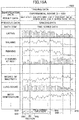
- FIG. 8A and FIG. 8B are first and second drawings illustrating an example of the training data stored in the training data storage unit. As illustrated in FIG. 8A and FIG. 8B , the training data 800 includes "identification data" and "result data" as items of header information.
- FIG. 8A also indicates that "judged result: having developed BRDC (period of development: day xx) and becoming severe (period of becoming severe: day yy)" is recorded as the result data.
- the example of FIG. 8B indicates that "judged result: no BRDC development" is recorded as the result data.
- both training data 800 related to the bovine that has developed BRDC and the training data 800' related to the bovine that has not developed BRDC are stored.
- the training data 800 includes "data items” and "time series data" as items of body information.
- the "data items” store respective data items of action data 750, non-action data 760, and vital data 770 generated by the experimental data processing unit 611.
- the "time series data” stores time series data of data items included in the action data 750, the non-action data 760, and the vital data 770 generated by the experimental data processing unit 611.
- a dashed line 850 illustrated over the "time series data" indicates the timing when a predetermined time period (see the arrow 840) has elapsed from the timing of being infected with BRDC.
- the learning unit 613 uses the time series data within the predetermined period of time, which is indicated by the arrow 840, among the time series data, in generating a learned model.
- the time series data before BRDC is developed is used because there are concerns that if the time series data after the BRDC development was used, the accuracy of detecting a sign the BRDC development before BRDC has been developed would be reduced. In other words, by using time series data before BRDC has been developed, the accuracy of detecting a sign of the BRDC development can be improved.
- a dashed line 850 illustrated over the "time series data" indicates the timing when a predetermined time period (see the arrow 840) has elapsed from the timing of being infected with BRDC.
- the learning unit 613 uses the time series data within the predetermined time period indicated by the arrow 840 among the time series data in generating a learned model.
- FIG. 8A and FIG. 8B the training data stored in the training data storage unit 614 in the learning phase is illustrated. It is assumed that the training data stored in the training data storage unit 614 in the sign detection and learning phase has the same configuration.
- FIG. 9 is a first drawing illustrating the learning unit in detail.
- the learning unit 613 generates a learned model to be installed in the sign detecting unit 624.
- the learning unit 613 includes a learning model 901 and a comparing modifying unit 902.
- the learning model 901 is an example of a machine learning unit, for example, a convolutional neural network (CNN) based learning model.
- the learning model 901 performs a process in response to the time series data (for the predetermined time period) of the training data (e.g., the training data 800 and 800') read from the training data storage unit 614 being input. Then, the learning model 901 outputs an output result (the BRDC development, the time of the BRDC development, becoming severe, the time of becoming severe, or no BRDC development) to the comparing modifying unit 902.
- CNN convolutional neural network
- the comparing modifying unit 902 calculates the error for the learning model 901 to perform machine learning. Specifically, the comparing modifying unit 902 calculates the error by comparing the following results.
- the comparing modifying unit 902 performs machine learning on the learning model 901 by changing model parameters in the learning model 901 based on the calculated error.
- the learning unit 613 illustrated in FIG. 9 generates a learned model by using the training data for all experimental bovines, stored in the training data storage unit 614, to perform machine learning on the learning model 901.
- the description assumes that the judged results include the BRDC development, the time of the BRDC development, becoming severe, the time of becoming severe, or no BRDC development. However, only one or more of these may be included in the judged results.
- the respective units of the detecting device 110 here, the feedlot data processing unit 622, the sign detecting unit 624, and the first output unit 625) will be described in detail.
- the feedlot data processing unit 622 of the detecting device 110 will be described in detail.
- the processing contents of the feedlot data processing unit 622 are substantially the same as the processing contents of the experimental data processing unit 611 of the learning device 111.
- sign detection data that is output from the feedlot data processing unit 622 and that is stored in the sign detection data storage unit 623 will be described here.
- FIG. 10 is a first drawing illustrating an example of the sign detection data stored in the sign detection data storage unit. As illustrated in FIG. 10 , the sign detection data 1001 includes "identification data" as an item of the header information.
- the sign detection data 1001 includes "data items” and “time series data” as items of the main body information.
- the "data items” store respective data items of the action data, the non-action data, and the vital data output from the feedlot data processing unit 622.
- the "time series data” stores the time series data of respective data items included in the action data, the non-action data, and the vital data output from the feedlot data processing unit 622.
- a dashed line 1030 illustrated over the "time series data” in FIG. 10 indicates the timing when the state check of the bovine is completed.
- a dashed line 1050 illustrated over the "time series data" in FIG. 10 indicates the timing when a predetermined time period (the arrow 1040) has elapsed since the fattening process has been started in the feedlot 140.
- the predetermined time period indicated by the arrow 1040 of FIG. 10 is approximately the same length as the predetermined time period indicated by the arrow 840 of FIG. 8A .
- the predetermined time period (the arrow 1040) is referred to as the sign monitoring period
- the time series data within the sign monitoring period is referred to as the sign monitoring data.
- FIG. 11 is a first drawing illustrating the sign detecting unit in detail. As illustrated in FIG. 11 , the sign detecting unit 624 includes a learned model 1101.
- the learned model 1101 is an example of an inference unit and is generated by the learning unit 613.
- the learned model 1101 infers information indicating whether BRDC will be developed and outputs an inference result in response to time series data (for the sign monitoring period) of the sign detection data (e.g., the sign detection data 1001) read from the sign detection data storage unit 623 being input.
- the information indicating whether BRDC will be developed includes information indicating that BRDC will be developed or information indicating that BRDC will not be developed, and either of these is output.
- the output of information indicating that BRDC will be developed refers to, for example, the output of a node including the "BRDC development” or the "BRDC development and becoming severe” in the output layer of the CNN constituting the learning model 901 of FIG. 9 as a result of inference.
- the output of information indicating that BRDC will not developed refers to, for example, the output of a node including "no BRDC" in the output layer of the CNN of FIG. 9 as a result of inference.
- the time series data of the sign detection data is input every predetermined time period (e.g., every 3 hours).
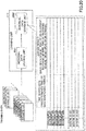
- the detecting device 110 In the sign detection and learning phase, the detecting device 110 generates the training data by using the sign detection data used to detect a sign and the judged results judged by the fattener manager after the fattening process is completed, and transmits the training data to the training data collecting unit 612. This allows the training data generated in the detecting device 110 to be stored in the training data storage unit 614.
- the example of FIG. 12 indicates that the result data 1201, in which "the judged result: the BRDC development (time of the development: day XX) and becoming severe (time of becoming severe: day YY)" is written, is associated with the sign detection data 1001.
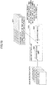
- FIG. 13 is a drawing illustrating an example of the detected result screen.
- the first output unit 625 generates and displays a detected result screen 1300 on the display device 406 in response to being notified by the sign detecting unit 624 that a sign of the BRDC development has been detected.
- the detected result screen 1300 includes a message indicating that a sign of the BRDC development has been detected. Additionally, the detected result screen 1300 includes the bovine ID that identifies the bovine on which a sign of the BRDC development has been detected. Furthermore, the detected result screen 1300 includes the date and time when a sign of the BRDC development has been detected, the body temperature and the body weight of the bovine at the time of the detection, and the like.
- the detected result screen 1300 may include the current position of the bovine on which a sign of the BRDC development has been detected.
- the BRDC sign detecting system 100 can detect a sign before BRDC is developed. As a result, losses associated with disposal of the bovines can be reduced. This is because detection and treatment at an early stage before the development or becoming severe can reduce the absolute amount of the bovine that has become severe.
- the increase in fattening costs due to the delay in shipment can be suppressed. This is because detection and treatment at an early stage before the development or becoming severe can shorten a time period until the bovine losing weight is recovered.
- treatment costs can be reduced. This is because detection and treatment at an early stage before the development or becoming severe can reduce the number of medications and reduce the cost of treatment in comparison with a case of the treatment of bovine after the development or becoming severe. This is also because a bovine that can recover spontaneously even if the bovine has developed BRDC can be identified before medication.
- the BRDC sign detecting system 100 performs the following processes.
- a sign of the BRDC development can be detected at an early stage in which BRDC is not developed.
- the description assumes that the time series data is input into the learning model 901.
- data input into the learning model 901 is not limited to the time series data.
- processed data generated by processing the time series data may be input.
- the change amount of the time series data from a reference data is calculated and the change amount is input to the learning model 901.
- time series data data other than the time series data may be input.
- previous data data related to the breeding before the experimental bovine is transferred to the experimental field 112
- the previous data is input into the learning model 901.
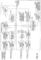
- FIG. 14 is a second drawing illustrating an example of the functional configurations of the learning device and the detecting device.
- a difference from FIG. 6 is that the learning device 111 of FIG. 14 also functions as a grazing data collecting unit 1410. Additionally, the difference is that in the learning device 111 of FIG. 14 , the functions of the training data collecting unit 1401 and the learning unit 1403 are different from the functions of the training data collecting unit 612 and the learning unit 613 illustrated in FIG. 6 .
- the detecting device 110 of FIG. 14 also functions as a grazing data collecting unit 1421, a fattening data generating unit 1425, and a second output unit 1426. Additionally, the difference is that in the detecting device 110 of FIG. 14 , the function of the sign detecting unit 1424 is different from the function of the sign detecting unit 624 illustrated in FIG. 6 .
- the grazing data collecting unit 1410 collects the previous data (i.e., data related to the breeding before the experimental bovine is transferred to the experimental field 112) and stores the previous data in the training data collecting unit 1401.
- the previous data refers to the grazing data (e.g., genetic information, past medical history, date of birth of the bovine, place of production, and the like) obtained by managing the bovine grass-fed in the pasture 180.
- the grazing data collecting unit 1410 collects the grazing data from the terminal device 181 through the network 120.
- the training data collecting unit 1401 is an example of an obtaining unit.
- the training data collecting unit 1401 stores the training data (including the corresponding judged results) generated in the experimental data processing unit 611 in a training data storage unit 1402.
- the training data collecting unit 1401 reads corresponding grazing data from the grazing data storage unit 1411 and stores the grazing data in the training data storage unit 1402, so as to be included in the training data.
- the training data collecting unit 1401 stores training data (including the corresponding judged result and the corresponding grazing data) generated in the detecting device 110 in the training data storage unit 1402.
- the learning unit 1403 performs machine learning on the learning model by using, for example, the training data stored in the training data storage unit 1402 to generate a learned model.
- the learning unit 1403 instead of the time series data, the change amount of the time series data from the reference data is input into the learning model 901. Additionally, in the learning unit 1403, the grazing data is input into the learning model 901 in addition to the time series data.
- the grazing data collecting unit 1421 collects the grazing data and stores the grazing data in the grazing data storage unit 1422.
- the grazing data stored in the grazing data storage unit 1422 the grazing data of the bovine for which the fattening process has been started in the feedlot 140 is stored in the sign detection data storage unit 1423 so as to be included in corresponding sign detection data.
- the sign detecting unit 1424 includes, for example, the learned model provided by the learning unit 1403.
- the sign detecting unit 1424 executes the learned model by using the sign detection data read from the sign detection data storage unit 1423 and detects a sign of the BRDC development.
- the sign detecting unit 1424 instead of the time series data, the change amount of the time series data from the reference data is input into the learned model.
- the sign detecting unit 1424 in addition to the time series data, the grazing data is input into the learned model.
- the fattening data generating unit 1425 reads the sign detection data (i.e., the sign detection data including the grazing data) from the sign detection data storage unit 1423 for the bovine transferred to the abattoir processor 183 upon the completion of the fattening process, and generates the fattening data.
- the sign detection data i.e., the sign detection data including the grazing data
- the second output unit 1426 transmits the generated fattening data to the terminal device 184 of the abattoir processor 183. This allows the abattoir processor 183 to obtain the fattening data for the bovine transferred from feedlot 140 that has completed the fattening process.
- FIG. 15A and FIG. 15B are fourth and fifth drawings illustrating examples of the training data stored in the training data storage unit.
- a difference from the training data 800 and 800' illustrated in FIG. 8A and FIG. 8B is that in the training data 1500 and 1500', the "previous data" is included as an item of the header information.
- the grazing data is stored in the "previous data".
- FIG. 16 is a second drawing illustrating the learning unit in detail.
- the learning unit 1403 includes a preprocessing unit 1601, a learning model 1602, and a comparing modifying unit 1603.
- the preprocessing unit 1601 generates data to be input into the learning model 1602 based on the training data.
- the data input into the learning model 1602 is as follows (see the reference numeral 1611).
- the grazing data is extracted from the item of the "previous data" of the training data (e.g., the training data 1500 and 1500') read from the training data storage unit 1402.
- the change amount of the time-series data of each data item is data representing the condition of the bovine and is calculated based on the time series data of the training data (e.g., the training data 1500 and 1500') read from the training data storage unit 1402. Specifically, for each data item (eating, walking, ..., and the like), by calculating a difference of the following data, the change amount of the time series data is calculated.
- the learning model 1602 is an example of a machine learning unit, for example a convolutional neural network (CNN) based learning model.
- the learning model 1602 performs a process by inputting the data (i.e., the grazing data, the change amount of the time series data (for the predetermined time period)) generated by the preprocessing unit 1601. Then, the learning model 1602 outputs the output result (i.e., the BRDC development, the time of the development, becoming severe, the time of becoming severe, or no BRDC development) to the comparing modifying unit 1603.
- the data i.e., the grazing data, the change amount of the time series data (for the predetermined time period)
- the learning model 1602 outputs the output result (i.e., the BRDC development, the time of the development, becoming severe, the time of becoming severe, or no BRDC development) to the comparing modifying unit 1603.
- the comparing modifying unit 1603 calculates the error for the learning model 1602 to perform machine learning. Specifically, the comparing modifying unit 1603 calculates the error by comparing the following data.
- a learned model is generated by performing machine learning on the learning model 1602 by using the training data for all experimental bovines stored in the training data storage unit 1402.
- FIG. 17 is a second drawing illustrating an example of the sign detection data stored in the sign detection data storage unit.
- a difference from the sign detection data 1001 illustrated in FIG. 10 is that the "previous data" is included as an item of the header information.
- the grazing data is stored in the "previous data".
- FIG. 18 is a second drawing illustrating the sign detecting unit in detail.
- the sign detecting unit 1424 includes a preprocessing unit 1801 and a learned model 1802.
- the preprocessing unit 1801 generates data to be input to the learned model 1802 based on the sign detection data.
- the data to be input into the learned model 1802 is as follows (see the reference numeral 1811).
- the grazing data is extracted from the item of the "previous data" of the sign detection data (e.g., the sign detection data 1701) read from the sign detection data storage unit 1423.
- the change amount of the time series data of each data item is calculated based on the time series data of the sign detection data (e.g., the sign detection data 1701) read from the sign detection data storage unit 1423. Specifically, for each data item (eating, walking, ..., and the like), by calculating a difference between the following data, the change amount in the time series data is calculated.
- the learned model 1802 is an example of an inference unit and is generated by the learning unit 1403.
- the learned model 1802 performs the process in response to the data (i.e., the grazing data, the change amount in the time series data (for the sign monitoring period)) generated by the preprocessing unit 1801 being input. Then, the learned model 1802 infers information indicating whether BRDC will be developed and outputs an inference result.
- the detecting device 110 In the sign detection and learning phase, the detecting device 110 generates the training data by using the sign detection data used to detect a sign and the judged result judged by the fattener manager after the fattening process is completed, and transmits the training data to the training data collecting unit 1401. This allows the training data generated in the detecting device 110 to be stored in the training data storage unit 1402.
- the BRDC sign detecting system 100 performs the following processes.
- the learning units 613 and 1403 include the learning models 901 and 1602, and the learned models are generated by performing machine learning using the training data.
- the sign detecting units 624 and 1424 execute the learned models by using the sign detection data and output the inference results.
- an individual data storage unit is provided in the learning units 613 and 1403, and the previous data and the time series data of each data item (or the change amount in the time series data of each data item) are stored for each individual bovine in association with the judged result.
- the sign detecting units 624 and 1424 contrast the following data and search for similar data.
- FIG. 20 is a third drawing illustrating the learning unit in detail.
- the learning unit 613 includes an individual data storing unit 2001.
- the individual data storing unit 2001 is an example of the storage unit.
- the time series data of each data item and the judged results read from the training data storage unit 614 are stored in the individual data storage unit 2002 in association with each other.
- FIG. 21 is a third drawing illustrating the sign detecting unit in detail. As illustrated in FIG. 21 , the sign detecting unit 624 includes a similarity degree determining unit 2101.
- the similarity degree determining unit 2101 is an example of a searching unit.
- the similarity degree determining unit 2101 searches for the time series data of each data item similar to the sign detection data (e.g., the sign detection data 1001) read from the sign detection data storage unit 623 from among the time series data of each data item stored in the individual data storage unit 2002.
- searching for the similar time series data of each data item is equivalent to inferring information indicating whether BRDC will be developed.
- the similarity degree determining unit 2101 outputs the judged result (i.e., the information indicating whether BRDC will be developed) associated with the searched time series data of each data item as an inference result.
- the BRDC sign detecting system 100 performs the following processes.
- the training data with respect to both a bovine (or the experimental bovine) that has developed BRDC and a bovine (or the experimental bovine) that does not develop BRDC, the training data is generated.
- the object of generating the training data is not limited to this, and, for example, the training data may be generated only for the bovine (or the experimental bovine) that has not developed BRDC.
- the sign detecting unit 624 outputs, as an inference result, information indicating that BRDC will be developed in a case where information indicating that BRDC will not developed is not output from the learned model 1101.
- information indicating that BRDC will be developed is output as an inference result.
- the training data may be divided into multiple similar groups, and machine learning may be performed for each group to generate the learned model.
- the learned model when installed in the sign detecting units 624 and 1424, the training data of the group used to generate a corresponding one of the learned models is stored in each of the sign detecting units 624 and 1424 in association with the corresponding learned model.
- the sign detecting units 624 and 1424 search for the training data similar to the sign detection data read from the sign detection data storage units 623 and 1423 and execute the learned models associated with the similar training data to detect a sign of the BRDC development.
- the sign detecting units 624 and 1424 when searching the training data similar to the sign detection data, compare the time series data during the predetermined period with each other.
- the item of the header information of the training data includes the "previous data” and records the grazing data (e.g., genetic information, past medical history, date of birth of the bovine, place of production, and the like).
- the grazing data e.g., genetic information, past medical history, date of birth of the bovine, place of production, and the like.
- data other than the grazing data may be recorded.
- machine learning is performed including the time of the development and the time of becoming severe.
- machine learning may be performed excluding the time of the development and the time of becoming severe.
- machine learning may be performed by replacing the time of the development and the time of becoming severe with a predetermined length of time range.
- isolation treatment or medication treatment is performed.
- it may be configured to perform neither medication treatment nor isolation treatment if the bovine does not become severe even if the information indicating that the BRDC will be developed is output as an inference. This can administer medication only to the bovine that will become severe among the bovines to which medication would have been administered, and not to administer medication to the bovines that are not required for medication. As a result, the effect of reducing the medication cost can be obtained.
- the learning device and the detecting device are separately configured, but the learning device and the detecting device may be integrally configured.
- the measurement sites include the head, the neck, and the belly, and the sensors are attached to the measurement sites.
- the sensors may be attached to other measurement sites.
- a method of attaching to each measurement site can be selected as desired.
- the experimental data collecting unit 610 or the feedlot data collecting unit 621 collects the image data, the acceleration data, the temperature data, and the sound data as the experimental data or the feedlot data.
- the data collected by the experimental data collecting unit 610 or the feedlot data collecting unit 621 is not limited to the image data, the acceleration data, the temperature data, and the sound data, and may be another data.
- the experimental data processing unit 611 or the feedlot data processing unit 622 generates the action data, the non-action data, and the vital data.
- the data generated by the experimental data processing unit 611 or the feedlot data processing unit 622 is not limited to the action data, the non-action data, and the vital data, and may be another data.
Landscapes
- Engineering & Computer Science (AREA)
- Life Sciences & Earth Sciences (AREA)
- Environmental Sciences (AREA)
- Theoretical Computer Science (AREA)
- Animal Husbandry (AREA)
- Software Systems (AREA)
- Physics & Mathematics (AREA)
- Biodiversity & Conservation Biology (AREA)
- General Physics & Mathematics (AREA)
- Business, Economics & Management (AREA)
- Evolutionary Computation (AREA)
- Artificial Intelligence (AREA)
- Mathematical Physics (AREA)
- General Engineering & Computer Science (AREA)
- Computing Systems (AREA)
- Medical Informatics (AREA)
- Data Mining & Analysis (AREA)
- Computer Vision & Pattern Recognition (AREA)
- Tourism & Hospitality (AREA)
- Strategic Management (AREA)
- Mining & Mineral Resources (AREA)
- General Business, Economics & Management (AREA)
- Economics (AREA)
- General Health & Medical Sciences (AREA)
- Marine Sciences & Fisheries (AREA)
- Health & Medical Sciences (AREA)
- Agronomy & Crop Science (AREA)
- Primary Health Care (AREA)
- Marketing (AREA)
- Human Resources & Organizations (AREA)
- Measuring And Recording Apparatus For Diagnosis (AREA)
- Image Analysis (AREA)
- Management, Administration, Business Operations System, And Electronic Commerce (AREA)
- Measurement And Recording Of Electrical Phenomena And Electrical Characteristics Of The Living Body (AREA)
Abstract
Description
- The present invention relates to a BRDC sign detecting system.
- Generally, a flow from breeding to sales in cattle is broadly divided into multiple processes (e.g. a grass feeding process, a fattening process, a processing process, and the like). Among these, because a feedlot is within a certain area, there is a problem in that cattle can easily get infected with bovine respiratory disease complex (BRDC).
- With respect to the above, for example, Non-Patent
Document 1 below proposes a system that automatically detects a bovine that has actually developed BRDC among bovines infected with BRDC. The system can identify a bovine that has developed BRDC earlier. - Non-Patent Document 1: Cargill, "Cargill brings facial recognition capability to farmers through strategic equity investment in Cainthus", [online], 31 January 2018 [searched on 31 July 2018], Internet (URL:https://www.cargill.com/2018/cargill-brings-facial-recognition-capability-to-farmers)
- If a bovine can be treated before a bovine has developed BRDC by identifying a sign, it is conceivable that various costs caused associated with the BRDC development and becoming severe BRDC may be reduced.
- According to one aspect, it is an object to provide a BRDC sign detecting system that detects a sign of BRDC.
- According to one aspect, a BRDC sign detecting system includes an obtaining unit configured to obtain, with respect to a bovine developing bovine respiratory disease complex (BRDC) within a time period required for a fattening process, data indicating a condition of the bovine during a predetermined time period in which the bovine did not yet develop the BRDC, and obtain data indicating a condition, during a predetermined time period, of a bovine that has not developed BRDC as of an end of the time period required for the fattening process, a machine learning unit configured to perform machine learning with respect to a correspondence relation between the obtained data indicating the condition during the predetermined time period and information indicating whether BRDC is developed, and an inference unit configured to infer, by inputting data indicating a condition of a new bovine during the predetermined time period into a learned model generated by performing the machine learning with respect to the correspondence relation, information indicating whether the new bovine will develop BRDC and output an inference result.
- A BRDC sign detecting system that detects a sign of BRDC can be provided.
-
-
FIG. 1 is a drawing illustrating an example of a system configuration of a BRDC sign detecting system; -
FIG. 2 is a drawing illustrating sensors attached to a bovine and positions where the sensors are attached; -
FIG. 3 is a drawing illustrating an example layout of an imaging device group in a feedlot; -
FIG. 4 is a drawing illustrating an example of a hardware configuration of a detecting device; -
FIG. 5 is a sequence diagram illustrating a flow of an entire process of the BRDC sign detecting system; -
FIG. 6 is a first drawing illustrating an example of functional configurations of a learning device and the detecting device; -
FIG. 7 is a drawing illustrating an experimental data processing unit in detail; -
FIG. 8A is a first drawing illustrating an example of training data stored in a training data storage unit; -
FIG. 8B is a second drawing illustrating an example of the training data stored in the training data storage unit; -
FIG. 9 is a first drawing illustrating the learning unit in detail; -
FIG. 10 is a first drawing illustrating an example of sign detection data stored in a sign detection data storage unit; -
FIG. 11 is a first drawing illustrating a sign detecting unit in detail; -
FIG. 12 is a third drawing illustrating an example of the training data stored in the training data storage unit; -
FIG. 13 is a drawing illustrating an example of a detected result screen; -
FIG. 14 is a second drawing illustrating an example of the functional configurations of the learning device and the detecting device; -
FIG. 15A is a fourth drawing illustrating an example of the training data stored in the training data storage unit; -
FIG. 15B is a fifth drawing illustrating an example of the training data stored in the training data storage unit; -
FIG. 16 is a second drawing illustrating the learning unit in detail; -
FIG. 17 is a second drawing illustrating an example of the sign detection data stored in the sign detection data storage unit; -
FIG. 18 is a second drawing illustrating the sign detecting unit in detail; -
FIG. 19 is a sixth drawing illustrating an example of the training data stored in the training data storage unit; -
FIG. 20 is a third drawing illustrating the learning unit in detail; and -
FIG. 21 is a third drawing illustrating the sign detecting unit in detail. - In the following, embodiments will be described with reference to the drawings. In the present specification and the drawings, components having substantially the same functional configuration are referenced by the same reference numerals, and the overlapping description is omitted.
- First, a system configuration of a BRDC sign detecting system will be described.
FIG. 1 is a drawing illustrating an example of the system configuration of the BRDC sign detecting system. - The BRDC
sign detecting system 100 is a system that detects a sign of the BRDC development in each bovine within afeedlot 140 during the fattening process. - As illustrated in
FIG. 1 , the BRDCsign detecting system 100 includes adetecting device 110, alearning device 111, animaging device group 130, a repeater 131 (and a sensor wirelessly connected to the repeater), aterminal device 150, and aterminal device 160. In the BRDCsign detecting system 100, thedetecting device 110 is communicatively connected to theimaging device group 130, therepeater 131, theterminal device 150, and theterminal device 160 through anetwork 120. - The detecting
device 110 receives image data captured by theimaging device group 130 and measurement data measured by sensors attached to a bovine through therepeater 131. The detectingdevice 110 detects a sign of the BRDC development in each bovine based on the received image data and the measured data (hereinafter referred to as feedlot data). - In a case of detecting a sign of the BRDC development, the detecting
device 110 determines a treatment to be administered to the bovine. As a result of the determination, if a medication treatment is to be taken to the bovine, a medication instruction is output to theterminal device 150. Additionally, as a result of the determination, if the bovine is to be given isolation treatment, an isolation instruction is output to theterminal device 160. - The
learning device 111 generates a learned model used when the detectingdevice 110 detects a sign of the BRDC development and provides the learned model to the detectingdevice 110. Thelearning device 111 collects captured image data and measured measurement data (hereinafter referred to as "experimental data") from the point of BRDC infection to the onset of BRDC symptoms for experimental bovines in anexperimental field 112 and generates the learned model on which machine learning is performed. - Additionally, the
learning device 111 modifies the generated learned model based on the feedlot data collected by the detectingdevice 110 with respect to the bovines in thefeedlot 140. - The
imaging device group 130 is disposed around thefeedlot 140 to capture images of the bovines in thefeedlot 140. Theimaging device group 130 transmits the captured image data to the detectingdevice 110 through thenetwork 120. - The
repeater 131 receives measurement data measured by sensors attached to the bovines in thefeedlot 140 through wireless communication and transmits the received measurement data to the detectingdevice 110 via thenetwork 120. - The
terminal device 150 is a terminal carried by a fattener manager who manages each of the bovines in thefeedlot 140 and notifies the fattener manager when the medication instruction is received from the detectingdevice 110. This enables the fattener manager to identify the bovine for which the medication instruction has been output and to administer medication. - The
terminal device 160 is a terminal carried by another fattener manager who manages each of the bovines in thefeedlot 140 and notifies another fattener manager when the isolation instruction is output from the detectingdevice 110. This enables another fattener manager to identify the bovine for which the isolation instruction has been output and to transfer the bovine from thefeedlot 140 to asanatorium 182 to provide the isolation treatment. -
FIG. 1 also illustrates devices other than the BRDCsign detecting system 100 and the transfer of bovines other than the fattening process. Among these, aterminal device 181 transmits grazing data obtained by managing bovines grass-fed in apasture 180 to the detectingdevice 110 through thenetwork 120. - Each of the bovines grass-fed at the
pasture 180 is transferred to thefeedlot 140 after the grass feeding process is completed and the fattening process is started in thefeedlot 140. At the time of transferring the bovine to thefeedlot 140, each of the bovines is checked and returned to thepasture 180 depending on a growth state. A bovine infected with BRDC or having developed BRDC is transferred to thesanatorium 182. - With respect to the above, each of the bovines for which the fattening process has been started in the
feedlot 140 is transferred to anabattoir processor 183 when the fattening process is completed after a time period required for the fattening process (i.e., the time period required for fattening) has elapsed. Aterminal device 184 manages each of the bovines for which the fattening process has been performed and that has been transferred to theabattoir processor 183. Specifically, theterminal device 184 collects data obtained during a time period in which each of the transferred bovines is processed and shipped by theabattoir processor 183, and transmits the data as process data to the detectingdevice 110. - Next, a sensor attached to each of the bovines in the
feedlot 140 will be described.FIG. 2 illustrates the sensors attached to the bovine and the position where the sensors are attached. - As illustrated in 2a of
FIG. 2 , to the bovines in thefeedlot 140, sensors having different sensor IDs for respective bovines are attached. The example in 2a ofFIG. 2 illustrates a sensor having a sensor ID = "001" attached to a bovine having a bovine ID = "001". - The sensors attached to each of the bovines include a group of multiple measurement elements, classified into the "acceleration," the "temperature," and the "sound" according to the measurement items. A measurement site is defined for each of the measurement items of the sensors attached to each of the bovines, and the measurement element is attached to each measurement site.
- For example, the "acceleration" is measured at the "head" and "belly" of the bovine, and a "first acceleration sensor" and a "second acceleration sensor" are attached to the respective parts. The "temperature" is measured at the "neck" of the bovine and a "temperature sensor" is attached to the part. Further, the "sound" is measured at the "belly" of the bovine and a "sound sensor" is attached to the part.
- In 2b of
FIG. 2 , an example of attaching the group of multiple measurement elements included in the sensor. In 2b ofFIG. 2 , a mountingfixture 201 is attached to the head of the bovine to perform various measurements at the head of the bovine. According to the example of 2a ofFIG. 2 , to the mountingfixture 201, the "first acceleration sensor" is attached. The mountingfixture 202 is attached to the neck of the bovine to perform various measurements on the neck of the bovine. According to the example of 2a ofFIG. 2 , to the mountingfixture 202, the "temperature sensor" is attached. Further, the mountingfixture 203 is attached to the belly of the bovine to perform various measurements at the belly of the bovine. According to the example of 2a ofFIG. 2 , to the mountingfixture 203, the "second acceleration sensor" and the "sound sensor" are attached. - Here, measurement data measured by the sensors is transmitted to the
repeater 131 at a predetermined period in association with the sensor ID by a transmitter (which is not illustrated). Thus, the detectingdevice 110 can receive the measurement data (i.e., first acceleration data, second acceleration data, temperature data, and sound data) associated with the sensor ID at a predetermined period. - Next, an example layout of an
imaging device group 130 in thefeedlot 140 will be described.FIG. 3 is a drawing illustrating an example layout of the imaging device group in the feedlot. The example ofFIG. 3 indicates a state in which fiveimaging devices feedlot 140 as theimaging device group 130. - As illustrated in
FIG. 3 , theimaging devices mounts feedlot 140 can be imaged. Imaging range in a height direction of theimaging devices - The
imaging devices mounts - In the example of
FIG. 3 , due to space limitation, only five imaging devices are illustrated, but the number of imaging devices disposed in thefeedlot 140 is not limited to five. - Next, a hardware configuration of the detecting
device 110 and thelearning device 111 will be described. Here, the detectingdevice 110 and thelearning device 111 have substantially the same hardware configuration, and thus the hardware configuration of the detectingdevice 110 will be described here. -
FIG. 4 is a drawing illustrating an example of the hardware configuration of the detecting device. As illustrated inFIG. 4 , the detectingdevice 110 includes a central processing unit (CPU) 401, a read only memory (ROM) 402, and a random access memory (RAM) 403. TheCPU 401, theROM 402, and theRAM 403 form what is called a computer. The detectingdevice 110 also includes anauxiliary storage device 404, anoperating device 405, adisplay device 406, acommunication device 407, and adrive device 408. Each hardware component of the detectingdevice 110 is interconnected through abus 409. - The
CPU 401 executes various programs installed in the auxiliary storage device 404 (e.g., a sign detection program which will be described later). - The
ROM 402 is a non-volatile memory and functions as a main storage device. TheROM 402 stores various programs, data, and the like required for theCPU 401 to execute various programs installed in theauxiliary storage device 404. Specifically, theROM 402 stores a boot program and the like, such as basic input/output system (BIOS) and extensible firmware interface (EFI). - The
RAM 403 is a volatile memory, such as a dynamic random access memory (DRAM) or a static random access memory (SRAM), and functions as a main storage device. TheRAM 403 provides a workspace where various programs installed in theauxiliary storage device 404 are deployed when the various programs are executed by theCPU 401. - The
auxiliary storage device 404 stores various programs, data collected by theCPU 401 executing various programs, data generated by processing the collected data, and the like. For example, a sign detection data storage unit, which will be described later, is implemented by theauxiliary storage device 404. - The operating
device 405 is an input device used when an administrator of the detectingdevice 110 inputs various instructions to the detectingdevice 110. Thedisplay device 406 is a display device that displays various information to the administrator of the detectingdevice 110. - The
communication device 407 is a communication device that connects to thenetwork 120 and communicates with each device (i.e., theimaging device group 130, therepeater 131, theterminal device 150, theterminal device 160, theterminal device 181, theterminal device 184, or the like). - The
drive device 408 is a device for setting arecording medium 410. Therecording medium 410 includes a medium that optically, electrically, or magnetically records information, such as a CD-ROM, a flexible disk, a magneto-optical disk, and the like. Additionally, therecording medium 410 may include a semiconductor memory or the like that electrically records information, such as a ROM, a flash memory, and the like. - The various programs installed in the
auxiliary storage device 404 are installed, for example, when the distributedrecording medium 410 is set in thedrive device 408 and the various programs recorded in therecording medium 410 are read by thedrive device 408. Alternatively, the various programs installed onauxiliary storage device 404 may be installed by downloading through thenetwork 120. - Next, a flow of an entire process of the BRDC
sign detecting system 100 will be described with reference toFIG. 5. FIG. 5 is a sequence diagram illustrating the flow of the entire process of the BRDC sign detecting system. - As illustrated in
FIG. 5 , the process of the BRDCsign detecting system 100 can be divided into a learning phase, a sign detection and learning phase, and a sign detection phase. - Among these, the learning phase is a phase in which a learned model used by the detecting
device 110 to detect a sign of the BRDC development is generated. The sign detection and learning phase is a phase in which the detectingdevice 110 detects a sign of the BRDC development using the learned model and modifies the learned model. Further, the detection phase is a phase in which the detectingdevice 110 detects a sign of the BRDC development by using the modified learned model. - As illustrated in
FIG. 5 , in response to starting the learning phase, in step S501, thelearning device 111 starts to monitor the bovines in theexperimental field 112 and collects experimental data. Although not illustrated inFIG. 1 , it is assumed that a system similar to the system in thefeedlot 140 is reproduced in theexperimental field 112. That is, thelearning device 111 can collect image data imaging the experimental bovine and measurement data measured by the sensors attached to the experimental bovine as the experimental data. - In step S502, an experimenter administers a virus or bacteria causing BRDC to each of the experimental bovines in the
experimental field 112 and infects each of the experimental bovines with BRDC. - In step S503, the experimenter judges whether any experimental bovine has developed BRDC and whether any BRDC experimental bovine has become severe from among the experimental bovines infected with BRDC. The judgement of whether each of the experimental BRDC bovines has developed BRDC and whether each of the experimental bovine has become severe is performed based on, for example, whether a clinical score exceeds a predetermined threshold, with the experimenter judging daily clinical scores.
- Specifically, on the bovine that has developed BRDC, symptoms, such as decreased appetite, coughing, nasal discharge, and high fever appear, and thus, by a combination of these factors, it is judged that BRDC has been developed. Additionally, symptoms of the severe BRDC become more severe than at the onset of BRDC, and symptoms, such as weakness, coughing, breathing difficulty, and extreme suppression of weight gain, appear. Therefore, by a combination of these factors, it is judged that the BRDC bovine has become severe. The judged result of whether each of the experimental bovines has developed BRDC and the judged result of whether each of BRDC bovines has become severe are input into the
learning device 111 in association with the experimental data. - In step S504, the
learning device 111 generates training data (which will be described below in detail with reference toFIG. 8A andFIG. 8B ) by using the experimental data and the judged result, and performs an analysis. Thelearning device 111, for example, performs machine learning on the learning model by using the training data to analyze the training data. - In step S505, the
learning device 111 generates a learned model by analyzing the training data. - In step S506, in the detecting
device 110, the learned model generated by thelearning device 111 is installed. In response to completing the installation of the learned model in the detectingdevice 110, the BRDCsign detecting system 100 transitions to the sign detection and learning phase. - Upon moving to the sign detection and learning phase, in step S511, each of the bovines is first transferred from the
pasture 180 to thefeedlot 140. - In step S512, the fattener manager of the
feedlot 140 checks a condition of each of the bovines transferred from thepasture 180. - In step S513, the detecting
device 110 starts collecting feedlot data by starting to monitor each of the bovines in thefeedlot 140. - In step S514, the fattener manager of the
feedlot 140 starts the fattening process for each of the bovines whose conditions are well. - In step S515, the detecting
device 110 uses the current feedlot data to detect a sign of the BRDC development for each of the bovines for which the fattening process has been started in thefeedlot 140. - In step S516, the fattener manager of the
feedlot 140 performs the isolation treatment or the medication treatment on a bovine on which a sign of the BRDC development is detected. - In step S517, in the
feedlot 140, the fattening process is terminated when the time required for the fattening process has elapsed. - In step S518, the fattener manager of the
feedlot 140 judges a condition of each of the bovines. The detectingdevice 110 generates training data (which will be described below in detail with reference toFIG. 12 ) by using results judged by the fattening manager of thefeedlot 140 and sign detection data used to detect a sign (which will be described below in detail with reference toFIG. 10 ), and transmits the training data to thelearning device 111. - In step S519, the
learning device 111 again performs machine learning on the learning model by using the training data transmitted from the detectingdevice 110. This enables thelearning device 111 to modify the learned model. - In step S520, in the detecting
device 110, the learned model modified by thelearning device 111 is installed. Upon completing the installation of the modified learned model, the BRDCsign detecting system 100 transitions to the sign detection phase. - Upon moving to the sign detection phase, in step S531, next bovines are transferred from the
pasture 180 to thefeedlot 140. - In step S532, the fattener manager of the
feedlot 140 checks a condition of each of the next bovines transferred from thepasture 180. - In step S533, the detecting
device 110 starts to collect the feedlot data by starting to monitor each of the bovines on thefeedlot 140. - In step S534, the fattener manager of the
feedlot 140 starts the fattening process for each of the bovines whose conditions are well based on a result of the check. - In step S535, the detecting
device 110 detects a sign of the BRDC development for each of the bovines for which the fattening process has been started in thefeedlot 140 by using the sign detection data generated based on the current feedlot data. - In step S536, the fattener manager of the
feedlot 140 performs the isolation treatment or the medication treatment on the bovine for which a sign of the BRDC development is detected. - In step S537, in the
feedlot 140, the fattening process is terminated when the time required for the fattening process has elapsed. - Next, functional configurations of the
learning device 111 and the detectingdevice 110 will be described.FIG. 6 is a first drawing illustrating an example of functional configurations of the learning device and the detecting device. - A learning program is installed in the
learning device 111 and, by executing the program, thelearning device 111 functions as an experimentaldata collecting unit 610, an experimentaldata processing unit 611, a trainingdata collecting unit 612, and alearning unit 613. - The experimental
data collecting unit 610 collects image data and measurement data transmitted from theexperimental field 112 as experimental data. Additionally, the experimentaldata collecting unit 610 obtains a judged result of whether the experimental bovine has developed BRDC and a judged result of whether the experimental BRDC bovine has become severe (information indicating whether BRDC has been developed) in association with the experimental data. - The experimental
data processing unit 611 is an example of a processing unit, and extracts a feature from the collected experimental data and analyze the extracted feature to generate training data for each individual bovine. - The training
data collecting unit 612 is an example of an obtaining unit. In the learning phase, the trainingdata collecting unit 612 stores training data (including corresponding judged results) generated in the experimentaldata processing unit 611, in the trainingdata storage unit 614. - In the sign detection and learning phase, the training
data collecting unit 612 stores training data (including corresponding judged results) generated in the detectingdevice 110, in the trainingdata storage unit 614. - In the learning phase, the
learning unit 613 performs machine learning on the learning model by using, for example, the training data stored in the trainingdata storage unit 614 to generate the learned model. The generated learned model is provided to the detectingdevice 110 and installed in asign detecting unit 624. - Additionally, in the sign detection and learning phase, the
learning unit 613 again performs machine learning on the learning model by using the training data newly stored in the trainingdata storage unit 614 to modify the learned model. The modified learned model is again provided to the detectingdevice 110 and installed in thesign detecting unit 624. - With respect to the above, the sign detection program is installed in the detecting
device 110. By executing the program, the detectingdevice 110 functions as a feedlotdata collecting unit 621, a feedlotdata processing unit 622, asign detecting unit 624, and afirst output unit 625. - The feedlot
data collecting unit 621 collects the image data and measurement data transmitted from thefeedlot 140 as the feedlot data. - The feedlot
data processing unit 622 is an example of a processing unit. The feedlotdata processing unit 622 extracts a feature from the collected feedlot data and analyzes the extracted feature to generate sign detection data for each individual bovine, and stores the sign detection data in a sign detectiondata storage unit 623. - The
sign detecting unit 624 includes, for example, the learned model provided by thelearning unit 613. Thesign detecting unit 624 executes the learned model by using the sign detection data read from the sign detectiondata storage unit 623 to detect a sign of the BRDC development. - If the
sign detecting unit 624 detects a sign of the BRDC development, thesign detecting unit 624 notifies thefirst output unit 625. - If the
first output unit 625 is notified by thesign detecting unit 624 of the detection of a sign of the BRDC development, thefirst output unit 625 outputs information that identifies the bovine, and notifies the administrator of the detectingdevice 110 of the bovine on which a sign of the BRDC development has been detected. - Although not explicitly illustrated in
FIG. 6 , it is assumed that the detectingdevice 110 has a function to generate training data (which will be described below in detail with reference toFIG. 12 ) by using the following data. - the sign detection data stored in the sign detection
data storage unit 623 - the results judged by the fattening manager of the
feedlot 140 - Next, each unit of the learning device 111 (here, the experimental
data processing unit 611 and the learning unit 613) will be described in detail. - First, the experimental
data processing unit 611 of thelearning device 111 will be described in detail.FIG. 7 is a drawing illustrating the experimental data processing unit in detail. As illustrated inFIG. 7 , the experimentaldata processing unit 611 includes afeature extracting unit 710, an actiondata analyzing unit 720, a non-actiondata analyzing unit 730, and a vitaldata analyzing unit 740. - The
feature extracting unit 710 extracts a feature from image data (i.e.,image data 1 to image data n) included in the experimental data. Additionally, thefeature extracting unit 710 extracts a feature from the measurement data (i.e., the first acceleration data, the second acceleration data, the temperature data, and the sound data) included in the experimental data. - The features extracted by the
feature extracting unit 710 include various features. Examples include the position coordinates that indicate the positions of the foots of each of the bovines. By calculating the feature, for example, the walking distance (or the number of steps taken while walking), the running distance (or the number of steps taken while running), and the like can be calculated by analyzing "walking" (or "running"), which is one of the items of the action data of the bovine. - The action
data analyzing unit 720 generatesaction data 750 by analyzing the feature extracted in thefeature extracting unit 710. As illustrated inFIG. 7 , theaction data 750 generated by the actiondata analyzing unit 720 includes, for example, the number of times eating per day, the walking distance per day (or the number of steps taken while walking), and the running distance per day (or the number of steps taken while running). - The
action data 750 generated by the actiondata analyzing unit 720 includes, for example, the number of times (or hours) of standing at rest per day, the number (or hours) of chewing in standing per day, the number (or hours) of lying at rest per day, and the number (or hours) of chewing in lying per day. - Further, the
action data 750 generated by the actiondata analyzing unit 720 includes, for example, the amount (or number) of drinking water per day, the amount (or number) of licking salt per day, the presence or absence of estrus, and the like. - The non-action
data analyzing unit 730 generatesnon-action data 760 by analyzing the feature extracted in thefeature extracting unit 710. As illustrated inFIG. 7 , thenon-action data 760 generated by the non-actiondata analyzing unit 730 includes, for example, the degree of inactivity. The degree of inactivity is an indicator of the degree indicating how much movements of the bovine are decreased from original movements. - The vital
data analyzing unit 740 generates vital data 770 by analyzing the feature extracted in thefeature extracting unit 710. As illustrated inFIG. 7 , the vital data 770 generated by the vitaldata analyzing unit 740 includes, for example, the volume of the lung sound per unit time, the body temperature per unit time, and the respiratory rate per unit time. - The vital data 770 generated by the vital
data analyzing unit 740 includes, for example, the presence or absence of nasal discharge, body weight, and the like. - The experimental
data processing unit 611 of thelearning device 111 generates the training data by using theaction data 750, thenon-action data 760, and the vital data 770 (i.e., data indicating conditions of the bovine) and stores the training data in the trainingdata storage unit 614. -
FIG. 8A andFIG. 8B are first and second drawings illustrating an example of the training data stored in the training data storage unit. As illustrated inFIG. 8A andFIG. 8B , thetraining data 800 includes "identification data" and "result data" as items of header information. - The example in
FIG. 8A indicates that the experimental bovine ID = "1001" is assigned as the identification data. The example ofFIG. 8B indicates that the experimental bovine ID = "1002" is assigned as the identification data. - The example in
FIG. 8A also indicates that "judged result: having developed BRDC (period of development: day xx) and becoming severe (period of becoming severe: day yy)" is recorded as the result data. The example ofFIG. 8B indicates that "judged result: no BRDC development" is recorded as the result data. As described, in the trainingdata storage unit 614, bothtraining data 800 related to the bovine that has developed BRDC and the training data 800' related to the bovine that has not developed BRDC are stored. - As illustrated in
FIG. 8A andFIG. 8B , thetraining data 800 includes "data items" and "time series data" as items of body information. - The "data items" store respective data items of
action data 750,non-action data 760, and vital data 770 generated by the experimentaldata processing unit 611. - The "time series data" stores time series data of data items included in the
action data 750, thenon-action data 760, and the vital data 770 generated by the experimentaldata processing unit 611. - In
FIG. 8A andFIG. 8B , a dashedline 810 illustrated over the "time series data" indicates the timing when each of the experimental bovines having the experimental bovine ID = "1001" and "1002" is transferred to theexperimental field 112. InFIG. 8A andFIG. 8B , a dashedline 830 illustrated over the "time series data" indicates the timing of infecting each of the experimental bovines having the experimental bovine ID = "1001" and "1002" with BRDC by administering a virus or bacterium causing BRDC to the experimental bovine. Thus, the time period indicated by thearrow 820 can be defined as a time period during which the experimental bovines having the experimental bovine ID = "1001" and "1002" are healthy (i.e., in a state of being not infected with BRDC) in theexperimental field 112. - In
FIG. 8A , a dashedline 850 illustrated over the "time series data" indicates the timing when a predetermined time period (see the arrow 840) has elapsed from the timing of being infected with BRDC. Here, the predetermined time period refers to a period shorter than the period until the experimental bovine having the experimental bovine ID = "1001" is finally judged to have developed BRDC and become severe. In a case of the bovine that has developed BRDC, thelearning unit 613, which will be described later, uses the time series data within the predetermined period of time, which is indicated by thearrow 840, among the time series data, in generating a learned model. - As described, the time series data before BRDC is developed is used because there are concerns that if the time series data after the BRDC development was used, the accuracy of detecting a sign the BRDC development before BRDC has been developed would be reduced. In other words, by using time series data before BRDC has been developed, the accuracy of detecting a sign of the BRDC development can be improved.
- In
FIG. 8B , a dashedline 850 illustrated over the "time series data" indicates the timing when a predetermined time period (see the arrow 840) has elapsed from the timing of being infected with BRDC. Here, the predetermined time period refers to a period until the experimental bovine having the experimental bovine ID = "1002" completes the fattening process without developing BRDC and completes the acquisition of the time-series data. In a case of the bovine that has not developed BRDC as of the end of the fattening process, thelearning unit 613, which will be described later, uses the time series data within the predetermined time period indicated by thearrow 840 among the time series data in generating a learned model. - Further, a dashed
line 860 illustrated over the "time series data" inFIG. 8A indicates the timing when it is judged that the experimental bovine having the experimental bovine ID = "1001" has developed BRDC. - Further, a dashed
line 870 illustrated over the "time series data" inFIG. 8A indicates the timing when it is judged that the experimental bovine having the experimental bovine ID = "1001" has become severe. - In
FIG. 8A andFIG. 8B , the training data stored in the trainingdata storage unit 614 in the learning phase is illustrated. It is assumed that the training data stored in the trainingdata storage unit 614 in the sign detection and learning phase has the same configuration. - Next, the
learning unit 613 of thelearning device 111 will be described in detail.FIG. 9 is a first drawing illustrating the learning unit in detail. Thelearning unit 613 generates a learned model to be installed in thesign detecting unit 624. - As illustrated in
FIG. 9 , thelearning unit 613 includes a learning model 901 and a comparing modifyingunit 902. - The learning model 901 is an example of a machine learning unit, for example, a convolutional neural network (CNN) based learning model. The learning model 901 performs a process in response to the time series data (for the predetermined time period) of the training data (e.g., the
training data 800 and 800') read from the trainingdata storage unit 614 being input. Then, the learning model 901 outputs an output result (the BRDC development, the time of the BRDC development, becoming severe, the time of becoming severe, or no BRDC development) to the comparing modifyingunit 902. - The comparing modifying
unit 902 calculates the error for the learning model 901 to perform machine learning. Specifically, the comparing modifyingunit 902 calculates the error by comparing the following results. - an output result output from the learning model 901 (the BRDC development, the time of the BRDC development, becoming severe, the time of becoming severe, or no BRDC development)
- a judged result included in a "result data" item of the training data read from the training data storage unit 614 (the BRDC development, the time of the BRDC development, becoming severe, the time of becoming severe, or no BRDC development).
- The comparing modifying
unit 902 performs machine learning on the learning model 901 by changing model parameters in the learning model 901 based on the calculated error. - The
learning unit 613 illustrated inFIG. 9 generates a learned model by using the training data for all experimental bovines, stored in the trainingdata storage unit 614, to perform machine learning on the learning model 901. - In the examples of the
training data 800 and 800', the description assumes that the judged results include the BRDC development, the time of the BRDC development, becoming severe, the time of becoming severe, or no BRDC development. However, only one or more of these may be included in the judged results. - Next, the respective units of the detecting device 110 (here, the feedlot
data processing unit 622, thesign detecting unit 624, and the first output unit 625) will be described in detail. - First, the feedlot
data processing unit 622 of the detectingdevice 110 will be described in detail. The processing contents of the feedlotdata processing unit 622 are substantially the same as the processing contents of the experimentaldata processing unit 611 of thelearning device 111. Thus, sign detection data that is output from the feedlotdata processing unit 622 and that is stored in the sign detectiondata storage unit 623 will be described here. -
FIG. 10 is a first drawing illustrating an example of the sign detection data stored in the sign detection data storage unit. As illustrated inFIG. 10 , thesign detection data 1001 includes "identification data" as an item of the header information. - The example of
FIG. 10 indicates that the bovine ID = "001" is assigned as the identification data. - As illustrated in
FIG. 10 , thesign detection data 1001 includes "data items" and "time series data" as items of the main body information. - The "data items" store respective data items of the action data, the non-action data, and the vital data output from the feedlot
data processing unit 622. - The "time series data" stores the time series data of respective data items included in the action data, the non-action data, and the vital data output from the feedlot
data processing unit 622. - Here, a dashed
line 1010 illustrated over the "time series data" inFIG. 10 indicates the timing when the bovine having the bovine ID = "001" is transferred to thefeedlot 140 and a state check is started. A dashedline 1030 illustrated over the "time series data" inFIG. 10 indicates the timing when the state check of the bovine is completed. Thus, thearrow 1020 can be considered as the period in which the bovine having the bovine ID = "001" is healthy (i.e., in a state of being not infected with BRDC). - A dashed
line 1050 illustrated over the "time series data" inFIG. 10 indicates the timing when a predetermined time period (the arrow 1040) has elapsed since the fattening process has been started in thefeedlot 140. Here, the predetermined time period indicated by thearrow 1040 ofFIG. 10 is approximately the same length as the predetermined time period indicated by thearrow 840 ofFIG. 8A . In the sign detection and learning phase, and the sign detection phase, the predetermined time period (the arrow 1040) is referred to as the sign monitoring period, and the time series data within the sign monitoring period is referred to as the sign monitoring data. - Next, a
sign detecting unit 624 of the detectingdevice 110 will be described in detail.FIG. 11 is a first drawing illustrating the sign detecting unit in detail. As illustrated inFIG. 11 , thesign detecting unit 624 includes a learnedmodel 1101. - The learned
model 1101 is an example of an inference unit and is generated by thelearning unit 613. The learnedmodel 1101 infers information indicating whether BRDC will be developed and outputs an inference result in response to time series data (for the sign monitoring period) of the sign detection data (e.g., the sign detection data 1001) read from the sign detectiondata storage unit 623 being input. - The information indicating whether BRDC will be developed includes information indicating that BRDC will be developed or information indicating that BRDC will not be developed, and either of these is output. The output of information indicating that BRDC will be developed refers to, for example, the output of a node including the "BRDC development" or the "BRDC development and becoming severe" in the output layer of the CNN constituting the learning model 901 of
FIG. 9 as a result of inference. The output of information indicating that BRDC will not developed refers to, for example, the output of a node including "no BRDC" in the output layer of the CNN ofFIG. 9 as a result of inference. - Into the learned
model 1101, the time series data of the sign detection data is input every predetermined time period (e.g., every 3 hours). This allows the learnedmodel 1101 to infer information indicating whether BRDC will be developed every predetermined period to output an inference result. That is, in the first embodiment, "detecting a sign of the BRDC development" or "notifying that a sign of the BRDC development is detected" is nothing else other than that the outputting, by the learnedmodel 1101, of information indicating that BRDC will be developed as a result of inference. - In the sign detection and learning phase, the detecting
device 110 generates the training data by using the sign detection data used to detect a sign and the judged results judged by the fattener manager after the fattening process is completed, and transmits the training data to the trainingdata collecting unit 612. This allows the training data generated in the detectingdevice 110 to be stored in the trainingdata storage unit 614. -
FIG. 12 is a third drawing illustrating an example of the training data stored in the training data storage unit. As illustrated inFIG. 12 , thesign detection data 1001 is associated with aresult data 1201 of the corresponding bovine (bovine ID = 001) and training data is generated for each individual bovine. - The example of
FIG. 12 indicates that theresult data 1201, in which "the judged result: the BRDC development (time of the development: day XX) and becoming severe (time of becoming severe: day YY)" is written, is associated with thesign detection data 1001. - Next, as processing details of the
first output unit 625 of the detectingdevice 110, a detected result screen, which is an example of a display screen generated by thefirst output unit 625, will be described.FIG. 13 is a drawing illustrating an example of the detected result screen. - The
first output unit 625 generates and displays a detectedresult screen 1300 on thedisplay device 406 in response to being notified by thesign detecting unit 624 that a sign of the BRDC development has been detected. - As illustrated in
FIG. 13 , the detectedresult screen 1300 includes a message indicating that a sign of the BRDC development has been detected. Additionally, the detectedresult screen 1300 includes the bovine ID that identifies the bovine on which a sign of the BRDC development has been detected. Furthermore, the detectedresult screen 1300 includes the date and time when a sign of the BRDC development has been detected, the body temperature and the body weight of the bovine at the time of the detection, and the like. - Although not explicitly illustrated in
FIG. 13 , the detectedresult screen 1300 may include the current position of the bovine on which a sign of the BRDC development has been detected. - Next, the effect of the BRDC
sign detecting system 100 will be described. As described above, the BRDCsign detecting system 100 can detect a sign before BRDC is developed. As a result, losses associated with disposal of the bovines can be reduced. This is because detection and treatment at an early stage before the development or becoming severe can reduce the absolute amount of the bovine that has become severe. - Additionally, the increase in fattening costs due to the delay in shipment can be suppressed. This is because detection and treatment at an early stage before the development or becoming severe can shorten a time period until the bovine losing weight is recovered.
- Further, treatment costs can be reduced. This is because detection and treatment at an early stage before the development or becoming severe can reduce the number of medications and reduce the cost of treatment in comparison with a case of the treatment of bovine after the development or becoming severe. This is also because a bovine that can recover spontaneously even if the bovine has developed BRDC can be identified before medication.
- As is obvious from the above description, the BRDC
sign detecting system 100 according to the first embodiment performs the following processes. - obtain, with respect to a bovine developing BRDC within a period required for a fattening process, data indicating a condition of the bovine during a predetermined period in which the bovine did not yet develop the BRDC (time series data for each data item), and obtain data indicating a condition, during a predetermined period, of the bovine that has not developed BRDC as of an end of the period of time required for the fattening process (time series data for each data item)
- perform machine learning with respect to a correspondence relation between the obtained data indicating the condition during the predetermined period and the information indicating whether BRDC has been developed
- infer, by inputting data indicating the condition of a new bovine during the predetermined time period into the learned model generated by performing machine learning with respect to the correspondence relationship, information indicating whether the new bovine will develop BRDC and output an inference result
- Thus, according to the first embodiment, a sign of the BRDC development can be detected at an early stage in which BRDC is not developed.
- In the first embodiment described above, the description assumes that the time series data is input into the learning model 901. However, data input into the learning model 901 is not limited to the time series data.
- For example, instead of the time series data, processed data generated by processing the time series data may be input. In a second embodiment, as the processed data, the change amount of the time series data from a reference data is calculated and the change amount is input to the learning model 901.
- In addition to the time series data, data other than the time series data may be input. In the second embodiment, as the data other than the time series data, previous data (data related to the breeding before the experimental bovine is transferred to the experimental field 112) is obtained and the previous data is input into the learning model 901.
- In the following, the second embodiment will be described in detail focusing on the differences from the first embodiment described above.
- First, functional configurations of the
learning device 111 and the detectingdevice 110 will be described.FIG. 14 is a second drawing illustrating an example of the functional configurations of the learning device and the detecting device. - A difference from
FIG. 6 is that thelearning device 111 ofFIG. 14 also functions as a grazingdata collecting unit 1410. Additionally, the difference is that in thelearning device 111 ofFIG. 14 , the functions of the trainingdata collecting unit 1401 and thelearning unit 1403 are different from the functions of the trainingdata collecting unit 612 and thelearning unit 613 illustrated inFIG. 6 . - A difference from
FIG. 6 is that the detectingdevice 110 ofFIG. 14 also functions as a grazingdata collecting unit 1421, a fatteningdata generating unit 1425, and asecond output unit 1426. Additionally, the difference is that in the detectingdevice 110 ofFIG. 14 , the function of thesign detecting unit 1424 is different from the function of thesign detecting unit 624 illustrated inFIG. 6 . - In the
learning device 111, the grazingdata collecting unit 1410 collects the previous data (i.e., data related to the breeding before the experimental bovine is transferred to the experimental field 112) and stores the previous data in the trainingdata collecting unit 1401. Here, in the present embodiment, the previous data refers to the grazing data (e.g., genetic information, past medical history, date of birth of the bovine, place of production, and the like) obtained by managing the bovine grass-fed in thepasture 180. The grazingdata collecting unit 1410 collects the grazing data from theterminal device 181 through thenetwork 120. - The training
data collecting unit 1401 is an example of an obtaining unit. In the learning phase, the trainingdata collecting unit 1401 stores the training data (including the corresponding judged results) generated in the experimentaldata processing unit 611 in a trainingdata storage unit 1402. At this time, the trainingdata collecting unit 1401 reads corresponding grazing data from the grazingdata storage unit 1411 and stores the grazing data in the trainingdata storage unit 1402, so as to be included in the training data. - In the sign detection and learning phase, the training
data collecting unit 1401 stores training data (including the corresponding judged result and the corresponding grazing data) generated in the detectingdevice 110 in the trainingdata storage unit 1402. - In the learning phase, the
learning unit 1403 performs machine learning on the learning model by using, for example, the training data stored in the trainingdata storage unit 1402 to generate a learned model. In thelearning unit 1403, instead of the time series data, the change amount of the time series data from the reference data is input into the learning model 901. Additionally, in thelearning unit 1403, the grazing data is input into the learning model 901 in addition to the time series data. - In the detecting
device 110, similarly with the grazingdata collecting unit 1410 of thelearning device 111, the grazingdata collecting unit 1421 collects the grazing data and stores the grazing data in the grazingdata storage unit 1422. Among the grazing data stored in the grazingdata storage unit 1422, the grazing data of the bovine for which the fattening process has been started in thefeedlot 140 is stored in the sign detectiondata storage unit 1423 so as to be included in corresponding sign detection data. - The
sign detecting unit 1424 includes, for example, the learned model provided by thelearning unit 1403. Thesign detecting unit 1424 executes the learned model by using the sign detection data read from the sign detectiondata storage unit 1423 and detects a sign of the BRDC development. In thesign detecting unit 1424, instead of the time series data, the change amount of the time series data from the reference data is input into the learned model. In thesign detecting unit 1424, in addition to the time series data, the grazing data is input into the learned model. - The fattening
data generating unit 1425 reads the sign detection data (i.e., the sign detection data including the grazing data) from the sign detectiondata storage unit 1423 for the bovine transferred to theabattoir processor 183 upon the completion of the fattening process, and generates the fattening data. - The
second output unit 1426 transmits the generated fattening data to theterminal device 184 of theabattoir processor 183. This allows theabattoir processor 183 to obtain the fattening data for the bovine transferred fromfeedlot 140 that has completed the fattening process. - Next, the training data stored in the training
data storage unit 1402 will be described in detail.FIG. 15A andFIG. 15B are fourth and fifth drawings illustrating examples of the training data stored in the training data storage unit. A difference from thetraining data 800 and 800' illustrated inFIG. 8A andFIG. 8B is that in thetraining data 1500 and 1500', the "previous data" is included as an item of the header information. As illustrated inFIG. 15A andFIG. 15B , in the present embodiment, the grazing data is stored in the "previous data". - Next, the
learning unit 1403 of thelearning device 111 will be described in detail.FIG. 16 is a second drawing illustrating the learning unit in detail. As illustrated inFIG. 16 , thelearning unit 1403 includes apreprocessing unit 1601, alearning model 1602, and a comparing modifyingunit 1603. - The
preprocessing unit 1601 generates data to be input into thelearning model 1602 based on the training data. The data input into thelearning model 1602 is as follows (see the reference numeral 1611). - the grazing data
- the change amount of the time series data of each data item (for the predetermined time period)
- Among these, the grazing data is extracted from the item of the "previous data" of the training data (e.g., the
training data 1500 and 1500') read from the trainingdata storage unit 1402. - The change amount of the time-series data of each data item (for the predetermined time period) is data representing the condition of the bovine and is calculated based on the time series data of the training data (e.g., the
training data 1500 and 1500') read from the trainingdata storage unit 1402. Specifically, for each data item (eating, walking, ..., and the like), by calculating a difference of the following data, the change amount of the time series data is calculated. - the time series data within the predetermined time period as indicated by the
arrow 840 - the reference data (e.g., a representative value (e.g., the average value) of the time-series data within the predetermined time period as indicated by the arrow 820)
- The
learning model 1602 is an example of a machine learning unit, for example a convolutional neural network (CNN) based learning model. Thelearning model 1602 performs a process by inputting the data (i.e., the grazing data, the change amount of the time series data (for the predetermined time period)) generated by thepreprocessing unit 1601. Then, thelearning model 1602 outputs the output result (i.e., the BRDC development, the time of the development, becoming severe, the time of becoming severe, or no BRDC development) to the comparing modifyingunit 1603. - The comparing modifying
unit 1603 calculates the error for thelearning model 1602 to perform machine learning. Specifically, the comparing modifyingunit 1603 calculates the error by comparing the following data. - the output result (i.e., the BRDC development, the time of the development, becoming severe, the time of becoming severe, or no BRDC development) output from the
learning model 1602 - the judged result (i.e., the BRDC development, the time of the development, becoming severe, the time of becoming severe, or no BRDC development) included in the item of the "result data" in the training data read from the training
data storage unit 1402 The comparing modifyingunit 1603 performs machine learning on thelearning model 1602 by changing model parameters in thelearning model 1602 based on the calculated error. - In the
learning unit 1403 illustrated inFIG. 16 , a learned model is generated by performing machine learning on thelearning model 1602 by using the training data for all experimental bovines stored in the trainingdata storage unit 1402. - Next, the sign detection data stored in the sign detection
data storage unit 1423 will be described in detail.FIG. 17 is a second drawing illustrating an example of the sign detection data stored in the sign detection data storage unit. A difference from thesign detection data 1001 illustrated inFIG. 10 is that the "previous data" is included as an item of the header information. - In the present embodiment, as illustrated in
FIG. 17 , the grazing data is stored in the "previous data". - Next, the
sign detecting unit 1424 of the detectingdevice 110 will be described in detail.FIG. 18 is a second drawing illustrating the sign detecting unit in detail. As illustrated inFIG. 18 , thesign detecting unit 1424 includes apreprocessing unit 1801 and a learnedmodel 1802. - The
preprocessing unit 1801 generates data to be input to the learnedmodel 1802 based on the sign detection data. The data to be input into the learnedmodel 1802 is as follows (see the reference numeral 1811). - the grazing data
- the change amount of the time series data of each data item (for the sign monitoring period)
- Among these, the grazing data is extracted from the item of the "previous data" of the sign detection data (e.g., the sign detection data 1701) read from the sign detection
data storage unit 1423. - The change amount of the time series data of each data item (for the sign monitoring period) is calculated based on the time series data of the sign detection data (e.g., the sign detection data 1701) read from the sign detection
data storage unit 1423. Specifically, for each data item (eating, walking, ..., and the like), by calculating a difference between the following data, the change amount in the time series data is calculated. - the time series data within the predetermined time period as indicated by the
arrow 1040 - the reference data (e.g., the representative value (e.g., the average value) of the time series data within the predetermined time period as indicated by the arrow 1020)
- The learned
model 1802 is an example of an inference unit and is generated by thelearning unit 1403. The learnedmodel 1802 performs the process in response to the data (i.e., the grazing data, the change amount in the time series data (for the sign monitoring period)) generated by thepreprocessing unit 1801 being input. Then, the learnedmodel 1802 infers information indicating whether BRDC will be developed and outputs an inference result. - In the sign detection and learning phase, the detecting
device 110 generates the training data by using the sign detection data used to detect a sign and the judged result judged by the fattener manager after the fattening process is completed, and transmits the training data to the trainingdata collecting unit 1401. This allows the training data generated in the detectingdevice 110 to be stored in the trainingdata storage unit 1402. -
FIG. 19 is a sixth drawing illustrating an example of the training data stored in the training data storage unit. As illustrated inFIG. 19 , the training data is generated for each individual bovine by associating thesign detection data 1001 with theresult data 1901 of the corresponding bovine (bovine ID = 001). - As is obvious from the above description, the BRDC
sign detecting system 100 according to the second embodiment performs the following processes. - obtain, with respect to a bovine developing BRDC within a period required for a fattening process, data indicating a condition of the bovine during a predetermined period in which the bovine did not yet develop the BRDC (i.e., the change amount of the time series data of each data item), and obtain data indicating a condition, during a predetermined period, of a bovine that has not developed BRDC as of an end of the time required for the fattening process (the change amount of the time series data of each data item)
- obtain grazing data for each of the bovines
- perform machine learning with respect to a correspondence relation between the obtained data indicating the condition during the predetermined period and the grazing data, and information indicating whether BRDC is developed
- infer, by inputting data indicating a condition during the predetermined time period and grazing data of a new bovine into a learned model generated by performing machine learning with respect to the correspondence relationship, information indicating whether the new bovine will develop BRDC and output an inference result
- This can detect a sign of the BRDC development at an early stage in which BRDC is not developed according to the second embodiment.
- In the above-described first and second embodiments, it has been described that the learning
units models 901 and 1602, and the learned models are generated by performing machine learning using the training data. In the above-described first and second embodiments, it has been described that thesign detecting units - With respect to the above, in a third embodiment, an individual data storage unit is provided in the learning
units sign detecting units - the previous data and time series data of each data item (or the change amount in the time series data of each data item) newly obtained
- the previous data and the time series data of each data item (or the change amount in the time series data of each data item) accumulated in the past In the third embodiment, the
sign detecting units - First, the learning unit of the
learning device 111 will be described in detail.FIG. 20 is a third drawing illustrating the learning unit in detail. - As illustrated in
FIG. 20 , thelearning unit 613 includes an individualdata storing unit 2001. - The individual
data storing unit 2001 is an example of the storage unit. The time series data of each data item and the judged results read from the trainingdata storage unit 614 are stored in the individualdata storage unit 2002 in association with each other. - Next, the
sign detecting unit 624 of the detectingdevice 110 will be described in detail.FIG. 21 is a third drawing illustrating the sign detecting unit in detail. As illustrated inFIG. 21 , thesign detecting unit 624 includes a similaritydegree determining unit 2101. - The similarity
degree determining unit 2101 is an example of a searching unit. The similaritydegree determining unit 2101 searches for the time series data of each data item similar to the sign detection data (e.g., the sign detection data 1001) read from the sign detectiondata storage unit 623 from among the time series data of each data item stored in the individualdata storage unit 2002. In the third embodiment, searching for the similar time series data of each data item is equivalent to inferring information indicating whether BRDC will be developed. - Further, the similarity
degree determining unit 2101 outputs the judged result (i.e., the information indicating whether BRDC will be developed) associated with the searched time series data of each data item as an inference result. - That is, in the third embodiment, "detecting a sign of the BRDC development" or "notifying that a sign of the BRDC development is detected" is nothing else other than the outputting, by the similarity
degree determining unit 2101, information indicating that BRDC will be developed in the judged result associated with the searched result, as an inference. - As is obvious from the above description, the BRDC
sign detecting system 100 according to the third embodiment performs the following processes. - store data indicating a condition of a bovine that has developed BRDC within a period required for a fattening process, during a predetermined period in which BRDC is not developed (i.e., the time series data of each data item or the change amount of the time series data of each data item) in association with information indicating that BRDC is developed
- store data indicating a condition, during a predetermined period, of a bovine that has not developed BRDC as of the end of the time required for the fattening process (i.e., the time series data of each data item or the change amount of the time series data of each data item) in association with information indicating that BRDC is not developed
- search for, in response to obtaining data indicating a condition of a new bovine during the predetermined time period (i.e., the time series data of each data item or the change amount of the time series data of each data item), the stored data similar to the data indicating the condition during the predetermined period
- This can detect a sign of the BRDC development at an early stage in which BRDC is not developed according to the third embodiment.
- In the above-described first to third embodiments, it has been described that as the training data, with respect to both a bovine (or the experimental bovine) that has developed BRDC and a bovine (or the experimental bovine) that does not develop BRDC, the training data is generated.
- However, the object of generating the training data is not limited to this, and, for example, the training data may be generated only for the bovine (or the experimental bovine) that has not developed BRDC. In this case, in the first and second embodiments, the
sign detecting unit 624 outputs, as an inference result, information indicating that BRDC will be developed in a case where information indicating that BRDC will not developed is not output from the learnedmodel 1101. In the third embodiment, in a case where the individualdata storage unit 2002 is searched, and no data is similar, information indicating that BRDC will be developed is output as an inference result. - In the above-described first embodiment, it has been described that only one learned model is generated, but multiple learned models may be generated. For example, the training data may be divided into multiple similar groups, and machine learning may be performed for each group to generate the learned model.
- In this case, when the learned model is installed in the
sign detecting units sign detecting units - Then, the
sign detecting units data storage units sign detecting units - In the above-described second embodiment, it has been described that the item of the header information of the training data includes the "previous data" and records the grazing data (e.g., genetic information, past medical history, date of birth of the bovine, place of production, and the like). However, in the "previous data", data other than the grazing data may be recorded.
- In the above-described first to third embodiments, it has been described that when performing machine learning on the learning model 901, machine learning is performed including the time of the development and the time of becoming severe. However, machine learning may be performed excluding the time of the development and the time of becoming severe. Alternatively, machine learning may be performed by replacing the time of the development and the time of becoming severe with a predetermined length of time range.
- In the above-described first to third embodiments, it has been described that if it is notified that a sign of the BRDC development is detected (if information indicating that BRDC will be developed is output as an inference), isolation treatment or medication treatment is performed. However, it may be configured to perform neither medication treatment nor isolation treatment if the bovine does not become severe even if the information indicating that the BRDC will be developed is output as an inference. This can administer medication only to the bovine that will become severe among the bovines to which medication would have been administered, and not to administer medication to the bovines that are not required for medication. As a result, the effect of reducing the medication cost can be obtained.
- In the above-described first to third embodiments, the learning device and the detecting device are separately configured, but the learning device and the detecting device may be integrally configured.
- In the above-described first to third embodiments, it has been described that the measurement sites include the head, the neck, and the belly, and the sensors are attached to the measurement sites. However, the sensors may be attached to other measurement sites. A method of attaching to each measurement site can be selected as desired.
- In the above-described first to third embodiments, it has been described that the experimental
data collecting unit 610 or the feedlotdata collecting unit 621 collects the image data, the acceleration data, the temperature data, and the sound data as the experimental data or the feedlot data. However, the data collected by the experimentaldata collecting unit 610 or the feedlotdata collecting unit 621 is not limited to the image data, the acceleration data, the temperature data, and the sound data, and may be another data. - In the above-described first embodiment, it has been described that the experimental
data processing unit 611 or the feedlotdata processing unit 622 generates the action data, the non-action data, and the vital data. However, the data generated by the experimentaldata processing unit 611 or the feedlotdata processing unit 622 is not limited to the action data, the non-action data, and the vital data, and may be another data. - It should be noted that the present invention is not limited to the above-described configurations, such as the configurations described in the above-described embodiments, and combinations with other elements. In these respects, modification can be made within the scope of the invention without departing from the spirit of the invention, and the configuration can be appropriately determined in accordance with the application form.
- The present application is based upon and claims priority to
Japanese Patent Application No. 2018-223742 filed on November 29, 2018 Japanese Patent Application No. 2019-205357 filed on November 13, 2019 -
- 100 :
- BRDC sign detecting system
- 110 :
- detecting device
- 111 :
- learning device
- 130 :
- imaging device group
- 131 :
- repeater
- 140 :
- feedlot
- 150, 160 :
- terminal device
- 610 :
- experimental data collecting unit
- 611 :
- experimental data processing unit
- 612 :
- training data collecting unit
- 613 :
- learning unit
- 621 :
- feedlot data collecting unit
- 622 :
- feedlot data processing unit
- 624 :
- sign detecting unit
- 625 :
- first output unit
- 710 :
- feature extracting unit
- 720 :
- action data analyzing unit
- 730 :
- non-action data analyzing unit
- 740 :
- vital data analyzing unit
- 800, 800' :
- training data
- 901 :
- learning model
- 902 :
- comparing modifying unit
- 1001 :
- sign detection data
- 1101 :
- learned model
- 1300 :
- detected result screen
- 1403 :
- learning unit
- 1424 :
- sign detecting unit
- 1601 :
- preprocessing unit
- 1801 :
- preprocessing unit
- 1802 :
- learned model
Claims (8)
- A BRDC sign detecting system comprising:an obtaining unit configured to obtain, with respect to a bovine developing bovine respiratory disease complex (BRDC) within a time period required for a fattening process, data indicating a condition of the bovine during a predetermined time period in which the bovine did not yet develop the BRDC, and obtain data indicating a condition, during a predetermined time period, of a bovine that has not developed BRDC as of an end of the time period required for the fattening process;a machine learning unit configured to perform machine learning with respect to a correspondence relation between the obtained data indicating the condition during the predetermined time period and information indicating whether BRDC is developed; andan inference unit configured to infer, by inputting data indicating a condition of a new bovine during the predetermined time period into a learned model generated by performing the machine learning with respect to the correspondence relation, information indicating whether the new bovine will develop BRDC and output an inference result.
- A BRDC sign detecting system comprising:an obtaining unit configured to obtain, with respect to a bovine developing bovine respiratory disease complex (BRDC) within a time period required for a fattening process, data indicating a condition of the bovine during a predetermined time period in which the bovine did not yet develop the BRDC, and data indicating a condition, during a predetermined time period, of a bovine that has not developed BRDC as of an end of the time period required for the fattening process;a storage unit configured to store a learned model generated by performing machine learning with respect to a correspondence relation between the obtained data indicating the condition during the predetermined time period and information indicating whether BRDC is developed, in association with data used to perform the machine learning; andan inference unit configured to, in response to obtaining data indicating a condition of a new bovine during the predetermined time period, infer information indicating whether the new bovine will develop BRDC, by searching data similar to the data indicating the condition of the new bovine during the predetermined time period in the data used to perform the machine learning and using the learned model associated with the similar data, and output an inference result.
- A BRDC sign detecting system comprising:an obtaining unit configured to obtain data indicating a condition, during a predetermined time period, of a bovine that has not developed bovine respiratory disease complex (BRDC) as of an end of a time period required for a fattening process;a machine learning unit configured to perform machine learning so that information indicating that BRDC will not be developed is output in response to the obtained data indicating the condition during the predetermined time period being input; andan inference unit configured to, in a case where in response to data indicating a condition of a new bovine during the predetermined time period being input into a learned model generated by performing the machine learning, information indicating that the new bovine will not develop BRDC is not output, output information indicating that the new bovine will develop BRDC, as an inference result.
- A BRDC sign detecting system comprising:a storage unit configured to store data indicating a condition, during a predetermined time period, of a bovine that has not developed bovine respiratory disease complex (BRDC) as of an end of a time period required for a fattening process;a searching unit configured to, in response to obtaining data indicating a condition of a new bovine during the predetermined time period, search for data similar to the data indicating the condition of the new bovine during the predetermined time period in the storage unit, and, in a case where no data is similar, output information indicating that the new bovine will develop BRDC as an inference result.
- The BRDC sign detecting system as claimed in claim 1, wherein the data indicating the condition during the predetermined time period is a change amount of time series data indicating the condition during the predetermined time period from data indicating a healthy condition prior to the predetermined time period.
- The BRDC sign detecting system as claimed in claim 1, wherein, in a case where information indicating the new bovine will develop BRDC is output as the inference result, information that identifies the new bovine is output.
- The BRDC sign detecting system as claimed in claim 1, wherein, in a case where information indicating the new bovine will develop BRDC is output as the inference result, and a determination is made that an isolation treatment to be performed, an isolation instruction including information that identifies the new bovine is output.
- The BRDC sign detecting system as claimed in claim 1, further comprising a processing unit configured to process image data imaging the bovine and measurement data measured by a sensor attached to the bovine to generate data indicating the condition of each individual bovine.
Applications Claiming Priority (3)
| Application Number | Priority Date | Filing Date | Title |
|---|---|---|---|
| JP2018223742 | 2018-11-29 | ||
| JP2019205357A JP7534041B2 (en) | 2018-11-29 | 2019-11-13 | BRDC Predictive Detection System |
| PCT/JP2019/045466 WO2020110862A1 (en) | 2018-11-29 | 2019-11-20 | Brdc sign detection system |
Publications (2)
| Publication Number | Publication Date |
|---|---|
| EP3888456A1 true EP3888456A1 (en) | 2021-10-06 |
| EP3888456A4 EP3888456A4 (en) | 2022-08-24 |
Family
ID=71085780
Family Applications (1)
| Application Number | Title | Priority Date | Filing Date |
|---|---|---|---|
| EP19891213.1A Withdrawn EP3888456A4 (en) | 2018-11-29 | 2019-11-20 | SYSTEM FOR DETECTION OF SIGNS OF ALL BOVINE RESPIRATORY DISEASES |
Country Status (4)
| Country | Link |
|---|---|
| US (1) | US12453336B2 (en) |
| EP (1) | EP3888456A4 (en) |
| JP (1) | JP7534041B2 (en) |
| AU (1) | AU2019387813B2 (en) |
Families Citing this family (1)
| Publication number | Priority date | Publication date | Assignee | Title |
|---|---|---|---|---|
| JP7607431B2 (en) * | 2020-10-13 | 2024-12-27 | 株式会社ブルーブックス | DATA MANAGEMENT SYSTEM, DATA MANAGEMENT METHOD, AND MACHINE LEARNING DATA MANAGEMENT PROGRAM |
Family Cites Families (9)
| Publication number | Priority date | Publication date | Assignee | Title |
|---|---|---|---|---|
| US20130281871A1 (en) * | 2012-04-18 | 2013-10-24 | Professional Beef Services, Llc | System and method for classifying the respiratory health status of an animal |
| ES2827789T3 (en) * | 2014-04-29 | 2021-05-24 | Intervet Int Bv | Animal evaluation system that considers the auscultation and evaluation of physiological responses in various environments |
| US10986817B2 (en) * | 2014-09-05 | 2021-04-27 | Intervet Inc. | Method and system for tracking health in animal populations |
| JP6745794B2 (en) * | 2015-04-24 | 2020-08-26 | 株式会社日本動物高度医療センター | Information processing system |
| JP2018023377A (en) * | 2016-08-08 | 2018-02-15 | 板垣 和子 | Artificial feeding cow's nipple, and swallowing aid for artificial feeding cow |
| WO2018075521A2 (en) | 2016-10-17 | 2018-04-26 | Context Ai, Llc | Systems and methods for medical diagnosis and biomarker identification using physiological sensors and machine learning |
| EP3553628A4 (en) * | 2016-12-08 | 2019-11-27 | Sony Corporation | DISPLAY CONTROL DEVICE, DISPLAY CONTROL METHOD, AND PROGRAM |
| JP6635968B2 (en) * | 2017-03-31 | 2020-01-29 | Nttテクノクロス株式会社 | Behavior identification device, behavior identification method, and program |
| WO2018180242A1 (en) | 2017-03-31 | 2018-10-04 | Nttテクノクロス株式会社 | Behavior specifying device, behavior specifying method and program |
-
2019
- 2019-11-13 JP JP2019205357A patent/JP7534041B2/en active Active
- 2019-11-20 AU AU2019387813A patent/AU2019387813B2/en active Active
- 2019-11-20 US US17/296,696 patent/US12453336B2/en active Active
- 2019-11-20 EP EP19891213.1A patent/EP3888456A4/en not_active Withdrawn
Also Published As
| Publication number | Publication date |
|---|---|
| JP7534041B2 (en) | 2024-08-14 |
| EP3888456A4 (en) | 2022-08-24 |
| JP2020092695A (en) | 2020-06-18 |
| US12453336B2 (en) | 2025-10-28 |
| AU2019387813B2 (en) | 2022-06-02 |
| AU2019387813A1 (en) | 2021-06-03 |
| US20220053737A1 (en) | 2022-02-24 |
| BR112021009480A2 (en) | 2021-08-10 |
Similar Documents
| Publication | Publication Date | Title |
|---|---|---|
| Peng et al. | Dam behavior patterns in Japanese black beef cattle prior to calving: Automated detection using LSTM-RNN | |
| Achour et al. | Unsupervised automated monitoring of dairy cows’ behavior based on Inertial Measurement Unit attached to their back | |
| Bowen et al. | Early prediction of respiratory disease in preweaning dairy calves using feeding and activity behaviors | |
| WO2011120529A1 (en) | Model for classifying an activity of an animal | |
| JP6618631B2 (en) | Computer system, animal diagnosis method and program | |
| Mei et al. | Identification of aflatoxin-poisoned broilers based on accelerometer and machine learning | |
| JP2021140754A (en) | Livestock disease management system, livestock disease management server, livestock disease management method, and livestock disease management program | |
| JPWO2016171077A1 (en) | Information processing system | |
| US12213453B2 (en) | Livestock stillbirthing alerting system | |
| Akbarein et al. | Applications and considerations of artificial intelligence in veterinary sciences: A narrative review | |
| JP7553971B2 (en) | EVALUATION APPARATUS, EVALUATION METHOD, EVALUATION PROGRAM, AND RECORDING MEDIUM | |
| CN112434577B (en) | Dairy cow lameness detection method and device | |
| Zhang et al. | Multimodal behavior recognition for dairy cow digital twin construction under incomplete modalities: A modality mapping completion network approach | |
| AU2019387813B2 (en) | BRDC sign detection system | |
| Biszkup et al. | Detectability of multi-dimensional movement and behaviour in cattle using sensor data and machine learning algorithms: Study on a Charolais bull | |
| KR102461183B1 (en) | Apparatus for detecting cattle estrus | |
| EP4501104A1 (en) | Animal behavior recording device, animal behavior recording method, and program | |
| CN120052271A (en) | Intelligent pet cage based on Internet of things | |
| Dalton et al. | Validation of HOBO Pendant® data loggers for automated step detection in two age classes of male turkeys: growers and finishers | |
| WO2020110862A1 (en) | Brdc sign detection system | |
| WO2021075574A1 (en) | Artificial intelligence model for predicting indications for test substances in humans | |
| BR112021009480B1 (en) | BRDC Signal Detection System | |
| Tran et al. | Cows' behavior classification using acceleration data: A new, effective, and simple approach | |
| Congiu et al. | Using tri-axial accelerometers data to predict behavior activity of grazing donkeys | |
| US20250040518A1 (en) | Health condition determination apparatus, health condition determination method, and program |
Legal Events
| Date | Code | Title | Description |
|---|---|---|---|
| STAA | Information on the status of an ep patent application or granted ep patent |
Free format text: STATUS: THE INTERNATIONAL PUBLICATION HAS BEEN MADE |
|
| PUAI | Public reference made under article 153(3) epc to a published international application that has entered the european phase |
Free format text: ORIGINAL CODE: 0009012 |
|
| STAA | Information on the status of an ep patent application or granted ep patent |
Free format text: STATUS: REQUEST FOR EXAMINATION WAS MADE |
|
| 17P | Request for examination filed |
Effective date: 20210506 |
|
| AK | Designated contracting states |
Kind code of ref document: A1 Designated state(s): AL AT BE BG CH CY CZ DE DK EE ES FI FR GB GR HR HU IE IS IT LI LT LU LV MC MK MT NL NO PL PT RO RS SE SI SK SM TR |
|
| DAV | Request for validation of the european patent (deleted) | ||
| DAX | Request for extension of the european patent (deleted) | ||
| A4 | Supplementary search report drawn up and despatched |
Effective date: 20220725 |
|
| RIC1 | Information provided on ipc code assigned before grant |
Ipc: A61B 7/00 20060101ALI20220719BHEP Ipc: G06Q 50/02 20120101ALI20220719BHEP Ipc: A01K 29/00 20060101AFI20220719BHEP |
|
| STAA | Information on the status of an ep patent application or granted ep patent |
Free format text: STATUS: THE APPLICATION IS DEEMED TO BE WITHDRAWN |
|
| 18D | Application deemed to be withdrawn |
Effective date: 20230222 |