EP3887955B1 - Mesh network - Google Patents
Mesh network Download PDFInfo
- Publication number
- EP3887955B1 EP3887955B1 EP19828527.2A EP19828527A EP3887955B1 EP 3887955 B1 EP3887955 B1 EP 3887955B1 EP 19828527 A EP19828527 A EP 19828527A EP 3887955 B1 EP3887955 B1 EP 3887955B1
- Authority
- EP
- European Patent Office
- Prior art keywords
- node
- nodes
- communication link
- multicast identification
- established
- Prior art date
- Legal status (The legal status is an assumption and is not a legal conclusion. Google has not performed a legal analysis and makes no representation as to the accuracy of the status listed.)
- Active
Links
Images








Classifications
-
- H—ELECTRICITY
- H04—ELECTRIC COMMUNICATION TECHNIQUE
- H04L—TRANSMISSION OF DIGITAL INFORMATION, e.g. TELEGRAPHIC COMMUNICATION
- H04L41/00—Arrangements for maintenance, administration or management of data switching networks, e.g. of packet switching networks
- H04L41/08—Configuration management of networks or network elements
- H04L41/0803—Configuration setting
- H04L41/0806—Configuration setting for initial configuration or provisioning, e.g. plug-and-play
-
- G—PHYSICS
- G06—COMPUTING OR CALCULATING; COUNTING
- G06F—ELECTRIC DIGITAL DATA PROCESSING
- G06F15/00—Digital computers in general; Data processing equipment in general
- G06F15/16—Combinations of two or more digital computers each having at least an arithmetic unit, a program unit and a register, e.g. for a simultaneous processing of several programs
- G06F15/163—Interprocessor communication
- G06F15/173—Interprocessor communication using an interconnection network, e.g. matrix, shuffle, pyramid, star, snowflake
-
- G—PHYSICS
- G06—COMPUTING OR CALCULATING; COUNTING
- G06F—ELECTRIC DIGITAL DATA PROCESSING
- G06F9/00—Arrangements for program control, e.g. control units
- G06F9/06—Arrangements for program control, e.g. control units using stored programs, i.e. using an internal store of processing equipment to receive or retain programs
- G06F9/46—Multiprogramming arrangements
- G06F9/54—Interprogram communication
- G06F9/542—Event management; Broadcasting; Multicasting; Notifications
-
- G—PHYSICS
- G06—COMPUTING OR CALCULATING; COUNTING
- G06F—ELECTRIC DIGITAL DATA PROCESSING
- G06F9/00—Arrangements for program control, e.g. control units
- G06F9/06—Arrangements for program control, e.g. control units using stored programs, i.e. using an internal store of processing equipment to receive or retain programs
- G06F9/46—Multiprogramming arrangements
- G06F9/54—Interprogram communication
- G06F9/546—Message passing systems or structures, e.g. queues
-
- H—ELECTRICITY
- H04—ELECTRIC COMMUNICATION TECHNIQUE
- H04L—TRANSMISSION OF DIGITAL INFORMATION, e.g. TELEGRAPHIC COMMUNICATION
- H04L12/00—Data switching networks
- H04L12/02—Details
- H04L12/16—Arrangements for providing special services to substations
- H04L12/18—Arrangements for providing special services to substations for broadcast or conference, e.g. multicast
-
- H—ELECTRICITY
- H04—ELECTRIC COMMUNICATION TECHNIQUE
- H04L—TRANSMISSION OF DIGITAL INFORMATION, e.g. TELEGRAPHIC COMMUNICATION
- H04L41/00—Arrangements for maintenance, administration or management of data switching networks, e.g. of packet switching networks
- H04L41/06—Management of faults, events, alarms or notifications
- H04L41/0654—Management of faults, events, alarms or notifications using network fault recovery
- H04L41/0659—Management of faults, events, alarms or notifications using network fault recovery by isolating or reconfiguring faulty entities
-
- H—ELECTRICITY
- H04—ELECTRIC COMMUNICATION TECHNIQUE
- H04L—TRANSMISSION OF DIGITAL INFORMATION, e.g. TELEGRAPHIC COMMUNICATION
- H04L41/00—Arrangements for maintenance, administration or management of data switching networks, e.g. of packet switching networks
- H04L41/06—Management of faults, events, alarms or notifications
- H04L41/0654—Management of faults, events, alarms or notifications using network fault recovery
- H04L41/0663—Performing the actions predefined by failover planning, e.g. switching to standby network elements
-
- H—ELECTRICITY
- H04—ELECTRIC COMMUNICATION TECHNIQUE
- H04L—TRANSMISSION OF DIGITAL INFORMATION, e.g. TELEGRAPHIC COMMUNICATION
- H04L41/00—Arrangements for maintenance, administration or management of data switching networks, e.g. of packet switching networks
- H04L41/20—Network management software packages
-
- H—ELECTRICITY
- H04—ELECTRIC COMMUNICATION TECHNIQUE
- H04L—TRANSMISSION OF DIGITAL INFORMATION, e.g. TELEGRAPHIC COMMUNICATION
- H04L45/00—Routing or path finding of packets in data switching networks
- H04L45/02—Topology update or discovery
- H04L45/026—Details of "hello" or keep-alive messages
-
- H—ELECTRICITY
- H04—ELECTRIC COMMUNICATION TECHNIQUE
- H04L—TRANSMISSION OF DIGITAL INFORMATION, e.g. TELEGRAPHIC COMMUNICATION
- H04L67/00—Network arrangements or protocols for supporting network services or applications
- H04L67/01—Protocols
- H04L67/12—Protocols specially adapted for proprietary or special-purpose networking environments, e.g. medical networks, sensor networks, networks in vehicles or remote metering networks
-
- H—ELECTRICITY
- H04—ELECTRIC COMMUNICATION TECHNIQUE
- H04L—TRANSMISSION OF DIGITAL INFORMATION, e.g. TELEGRAPHIC COMMUNICATION
- H04L69/00—Network arrangements, protocols or services independent of the application payload and not provided for in the other groups of this subclass
- H04L69/16—Implementation or adaptation of Internet protocol [IP], of transmission control protocol [TCP] or of user datagram protocol [UDP]
-
- H—ELECTRICITY
- H04—ELECTRIC COMMUNICATION TECHNIQUE
- H04W—WIRELESS COMMUNICATION NETWORKS
- H04W40/00—Communication routing or communication path finding
- H04W40/24—Connectivity information management, e.g. connectivity discovery or connectivity update
-
- H—ELECTRICITY
- H04—ELECTRIC COMMUNICATION TECHNIQUE
- H04W—WIRELESS COMMUNICATION NETWORKS
- H04W84/00—Network topologies
- H04W84/18—Self-organising networks, e.g. ad-hoc networks or sensor networks
Definitions
- the present disclosure relates to computer networks. More particularly, this disclosure relates to a system and method for establishing and maintaining a mesh network.
- Middleware is computer software that provides services to software applications beyond those available from the operating system. It can be described as "software glue”. Middleware makes it easier for software developers to implement communication and input/output.
- middleware commonly refers to software that enables communication and management of data in distributed applications.
- middleware is "those services found above the transport (e.g., over TCP/IP) layer set of services but below the application environment" (e.g., below application-level APIs). In this more specific sense middleware can be described as the dash (“-”) in client-server, or the -to- in peer-to-peer.
- Middleware includes web servers, application servers, content management systems, and similar tools that support application development and delivery.
- US2018/0212863A1 proposes a wireless network device.
- each receiving node in response to a subsequent multicast identification message from the broadcasting node, each receiving node adds the broadcasting node to the token register, along with an indication that a communication link has been established between the receiving node and the broadcasting node. Further, in response to each multicast identification message, each receiving node adds an indication of other nodes (if any) identified in the multicast identification message for which a communication link has not been established to the corresponding token register. Accordingly, the token register in each receiving node includes an indication of nodes identified in a multicast identification message, but where no (direct) communication link is established. This process continues until there is a communication link between each (online) node in the mesh network, such that the mesh network is a fully connected mesh network.
- FIG. 1 illustrates an example of a system 50 for establishing and maintaining a peer-to-peer (e.g., serverless) fully connected mesh network of N number of nodes 52, where N is an integer greater than or equal to two.
- peer-to-peer e.g., serverless
- fully connected mesh network indicates that each node 52 eventually has a direct connection to every other node 52.
- the N number of nodes 52 can be representative of software services (e.g., an application and middleware) that execute on a computing platform 54.
- FIG. 1 illustrates one computing platform, it is understood that there could be multiple computing platforms.
- the system 50 could be implemented on an aircraft, wherein each of the N number of nodes 52 represent different software services for controlling a different portion of the aircraft.
- Each of the nodes 52 can include a middleware application to facilitate communications between nodes 52.
- the middleware can provide an isolated runtime environment for a software application executing thereon.
- each of the N number of nodes 52 can communicate with a standard communications protocol such as a communication protocol within the Transmission Control Protocol Internet Protocol (TCIP/IP) stack. More specifically, in some examples, the nodes 52 can communicate via the Transmission Control Protocol (TCP) or the User Datagram Protocol (UDP).
- TCP Transmission Control Protocol
- UDP User Datagram Protocol
- node 2 may complete its startup process before node 3, such that node 2 is online prior to node 3.
- the sequence of starting each of the N number of node 52 can be based, for example, on factors (e.g., network latency, operating system priorities and/or environmental factors) that may be outside of the control of the computing platform 54.
- Each node 52 stores a token register 56 that tracks nodes 52 on the mesh network. More particularly, the token register 56 of each node 52 stores data that identifies information characterizing the node 52 associated with the token register 56. Additionally, the token register 56 of each node 52 stores data for nodes 52 on the mesh network that have established a communication link with the node 52 associated with the token register 56. Further, the token register 56 of each node 52 stores data for nodes 52 on the mesh network that have not established a communication link with the node 52 associated with the token register 56 but have been identified in a multicast identification message from at least one other node 52.
- the token register 56 for the given node identifies (i) the given node 52 (itself) (ii) each other node 52 that the given node 52 has established communication link with and (iii) each node 52 for which a communication link has not been established, but has been identified in a multicast identification message from another node 52.
- node 3 upon node 3 coming online (e.g., completes the startup process), node 3 receives the next multicast identification message broadcast by node 1. In response to receiving the next multicast identification message, node 3 establishes (opens) a communication link from node 3 to node 1.
- the communication link could be a TCP connection, a UDP connection or a connection using a different protocol.
- node 1 updates the token register of node 1 to add an indication that a communication link has been established with node 3.
- node 3 also broadcasts the multicast identification messages at the transient state rate. Since node 2 is not yet online (e.g., has not completed the startup process) node 2 does not receive the multicast identification message from node 3. However, since at this point in the given example, node 1 is online, node 1 receives the multicast identification message.
- the multicast identification message from node 3 includes the unique identifier of node 3 and data characterizing the token register 56 of node 3.
- the unique identifier includes a network address (e.g., IP address) and an open port number for a communication link to node 3. More generally, the unique identifier sent by a given node 52 in a multicast identification message includes information for establishing a communication link with the given node.
- node 1 In response to receipt of the multicast identification message, node 1 opens a communication link with node 3. Additionally, in a subsequent multicast identification message, node 1 provides data characterizing the token register 56 of node 1 to node 3 as well as the unique identifier of node 1 (e.g., the IP address and open port number). In response to receipt of the data characterizing the token register 56 of node 1, node 3 updates the token register 56 of node 3. More particularly, node 3 adds an indication to the token register 56 that a communication link has been established with node 1.
- node 2 comes online.
- node 2 broadcasts a multicast identification message that includes the unique identifier (e.g., IP address and open port number) of node 2.
- the unique identifier e.g., IP address and open port number
- node 1 receives the first multicast identification message from node 2, but that node 3 does not receive the multicast identification message.
- the multicast identification message may not be received by every online node 52 on the mesh network due to communication collisions and/or lost packets on the mesh network.
- node 1 in response to the multicast identification message, node 1 establishes a communication link with node 2 and provides the data characterizing the token register 56 of node 1 to node 2 in a subsequent multicast identification message.
- node 2 In response to receipt of the data characterizing the token register 56 of node 1, node 2 updates the token register 56 of node 2. In particular, node 2 adds an indication to the token register 56 that a communication link has been established with node 1 and another indication for node 3 indicating that node 3 is on the mesh network, but that a communication link has not been established with node 3. That is, at this point of the given example, the token register of node 3 has two different indicators, a given indicator for nodes 52 in the mesh network that have established communication links with and another indicator for nodes for which a communication link has not been established, but for which another node (e.g., node 1) has identified as being a member of the mesh network.
- another node e.g., node 1
- node 1 in a subsequent multicast identification message, node 1 provides data characterizing an updated status of the token register of node 1 to node 3.
- node 2 In response to the data characterizing the updated token register 56 of node 1, node 2 updates the token register 56 of node 2.
- node 2 stores data in the token register 56 indicating that node 3 is a member of the mesh network, and that no communication link has been established with node 2.
- each node 52 of the system 50 In subsequent multicast identification messages broadcast by each node 52 of the system 50, the data characterizing the corresponding token register 56 identifies every node on the mesh network. Thus, after a predetermined amount of time (e.g., 5-10 seconds), the mesh network is considered to be in a steady state. In such a situation, after the predetermined amount of time, each node 52 can reduce the rate of broadcasting the multicast identification messages from the transient state rate to a steady state rate. As one example, in the steady state rate, each node 52 broadcasts the multicast identification messages at a rate that is at least one-half less than the transient state rate to reduce network traffic on the mesh network. Thus, if a given node 52 broadcasts the multicast identification messages at a rate of one (1) message per second in the transient state rate, the given node would broadcast the multicast identification messages at a steady state rate of one (1) message every two (2) seconds or slower.
- a predetermined amount of time e.g., 5-10 seconds
- node 3 goes offline (becomes disabled).
- node 3 may go offline, for example, due to a failure in software executing on node 3.
- node 3 may go offline in a situation where an aircraft has sustained damage in a region where physical components of the system 50 support node 3.
- the attempt fails upon either node 1 or node 2 (the remaining function nodes 52) attempting to send a message to the offline node (node 2), the attempt fails.
- a failure could be detected, for example, with a lack of acknowledgement to the message sent.
- both remaining online nodes 52 node 1 and node 2 detecting that the corresponding token registers do not contain any other nodes in the mesh network
- the mesh network returns to the steady state.
- both nodes, nodes 1 and 2 reduce the rate of transmitting the multicast identification messages from the transient state rate to the steady state rate.
- Each token register 104 includes an identification of the corresponding node 102, and a given indication for nodes 102 (if any) within the mesh network with which the corresponding node 102 has established a communication link. Additionally, each token register 104 includes another indication for nodes (if any) within the mesh network that have been identified by another node 102, but where a communication link is not established.
- node 1 provides data characterizing the token register 104 of node 1, which identifies node 1 and node 3.
- node 3 adds node 1 to the token register 104 of node 3 along with a given indication that communication link has been established with node 1.
- node 2 modifies its token register 104. More particularly, node 2 adds node 1 to the token register 104 of node 2 along with the given indication that the communication link 122 has been established with node 1. Additionally, node 2 adds node 3 to the token register 104 of node 2 along with another indication that a communication link has not been established with node 3. As illustrated in FIG. 2E , nodes 102 on the mesh network for which a communication link has not been established are represented in token registers 104 with inverted coloring, as indicated by reference number 126.
- a subsequent multicast identification message 120 broadcast by node 2 is received at node 3.
- node 3 establishes a communication link with node 2 on the open port of node 2, as indicated by an arrow 130.
- node 3 provides data characterizing the token register 104 of node 3 to node 2 (and node 1).
- node 2 changes the token register 104 of node 2 to indicate that the communication link 130 is established with node 3.
- a subsequent multicast identification message 140 broadcast by node 4 is received by node 1, node 2, node 3 and node 4.
- node 1 opens a communication link indicated by an arrow 154 with node 4.
- node 4 modifies its token register 104 to include the given indication that the communication link 154 has been established with node 1.
- node 4 opens a communication link indicated by an arrow 156 on the open port of node 4.
- node 1 modifies its token register 104 to include the given indication that the communication link 154 has been established with node 4.
- each of the communication links 142, 152 and 154 are severed, as indicated by the dashed lines 142, 152 and 154. Accordingly, in this situation, node 1, node 2 and node 3 switch back to the transient mode, increasing the rate of broadcast of the multicast identification messages from the steady-state rate to the transient state rate.
- node 1, node 2 and node 3 upon detecting that node 4 is offline, modify their respective token registers 104 to indicate that node 4 is a node on the mesh network, but that a communication link has not been established with node 4. Further, after a predetermined amount of time (e.g., 5-10 seconds), as illustrated in FIG. 2N , node 1, node 2 and node 3 modify their respective token registers 104 to remove node 4 from the mesh network. Additionally, in an example where no additional nodes 102 come online within a threshold time (e.g., 5-10 seconds), the resultant mesh network is a fully connected mesh network between three (3) nodes 102. Thus, the mesh network is in the steady state, and in such a situation, node 1, node 2 and node 3 reduce a rate of broadcasting the multicast identification messages from the transient state rate to the steady state rate.
- a threshold time e.g., 5-10 seconds
- each of the nodes 102 can be brought online and/or go offline in a non-deterministic order. Moreover, the middleware that facilitates communication of the nodes 102 can delay messages until each corresponding token register 104 indicates that a communication link has been established. In this manner, delays due to re-sending of messages and/or collisions on the mesh network can be curtailed. Furthermore, as demonstrated, the system 100 is serverless, such that no single point of failure of the system 100 exists. In fact, as demonstrated in FIGS. 2M-2N , each node 102 is configured to take remedial action in response to detecting another node 102 going offline.
- FIG. 3 illustrates an example of a computing platform 200 that can support N number of nodes 202, where N is an integer greater than or equal to one (1), such as the nodes 52 of FIG. 1 and/or 102 of FIGS. 2A-2N .
- the computing platform 200 includes hardware 204.
- the hardware 204 includes a non-transitory memory (e.g., volatile memory and/or non-volatile memory) for storing machine readable instructions and a processing unit (e.g., one or more processor cores) for accessing the memory and executing the machine-readable instructions.
- the memory can be implemented as a hard disk drive, a solid-state drive, flash memory, random access memory, or any combination thereof.
- FIG. 4 illustrates an example of a system 250 that could be employed to implement the system 50 of FIG. 1 and/or the system 100 of FIGS. 2A-2N .
- the system 250 includes three (3) computing platforms 252. Each computing platform 252 can be representative of an instance of the computing platform 200 of FIG. 3 .
- the system 250 is provided as an example of software that could execute on a combat rated aircraft.
- Computing platform 2 can include, for example, a landing gear node 264 that can be representative of software for controlling landing gear of the aircraft. Further, computing platform 3 can include a weapons node 266 for controlling operations of weapons systems for the aircraft. Each of the navigation node 260, the controls node 262, the landing gear node 264 and the weapons node 266 can be brought online or offline in a non-deterministic manner, as described herein. Moreover, as illustrated, a bi-directional communication links 270 (which can represent two one-way communication links) connect each node in the system 250 to every other node in the system 250. In this manner, the system 250 operates a fully-connected mesh network. Additionally, the resultant mesh network of the system 250 is serverless, such that the system 250 does not have a single point of failure.
- FIG. 5 illustrates an example of a method 300 for establishing and maintaining a mesh network amongst a plurality of nodes operating on a computing platform.
- the method 300 can be executed by a given node (e.g., a node 52 of FIG. 1 and/or a node 102 of FIGS. 2A-2N ).
- a given node e.g., a node 52 of FIG. 1 and/or a node 102 of FIGS. 2A-2N .
- the given node initializes an application executing thereon, such that the given node is brought online.
- the node broadcasts multicast identification messages at a transient state rate.
- the node receives a multicast identification message broadcast by another node on the mesh network.
Landscapes
- Engineering & Computer Science (AREA)
- Computer Networks & Wireless Communication (AREA)
- Signal Processing (AREA)
- Theoretical Computer Science (AREA)
- Software Systems (AREA)
- Physics & Mathematics (AREA)
- General Engineering & Computer Science (AREA)
- General Physics & Mathematics (AREA)
- Computer Hardware Design (AREA)
- Health & Medical Sciences (AREA)
- Computing Systems (AREA)
- General Health & Medical Sciences (AREA)
- Medical Informatics (AREA)
- Multimedia (AREA)
- Computer Security & Cryptography (AREA)
- Mathematical Physics (AREA)
- Data Exchanges In Wide-Area Networks (AREA)
- Hardware Redundancy (AREA)
- Mobile Radio Communication Systems (AREA)
Description
- This application claims priority from
U.S. Patent Application Serial No. 16/250927, filed 17 January 2019 - The present disclosure relates to computer networks. More particularly, this disclosure relates to a system and method for establishing and maintaining a mesh network.
- A computing platform or digital platform refers to the environment in which a piece of software is executed. A computing platform may be the hardware or the operating system (OS), even a web browser and associated application programming interfaces, or other underlying software, as long as the program code is executed with it. Computing platforms have different abstraction levels, including a computer architecture, an OS, or runtime libraries. A computing platform is the stage on which computer programs can run.
- Middleware is computer software that provides services to software applications beyond those available from the operating system. It can be described as "software glue". Middleware makes it easier for software developers to implement communication and input/output. The term middleware commonly refers to software that enables communication and management of data in distributed applications. As one definition, middleware is "those services found above the transport (e.g., over TCP/IP) layer set of services but below the application environment" (e.g., below application-level APIs). In this more specific sense middleware can be described as the dash ("-") in client-server, or the -to- in peer-to-peer. Middleware includes web servers, application servers, content management systems, and similar tools that support application development and delivery.
US2018/0212863A1 proposes a wireless network device.US2007147334A1 proposes a communication device arranged to delay a procedure for joining a network until it detects activity on the network. KELSEY SILICON LABS R: "Mesh Link Establishment; draft-ietf-6lo-mesh-link-establishment-00.txt",MESH LINK ESTABLISHMENT; DRAFT-IETF-6LO-MESH-LINK-ESTABLISHMENT-00.TXT, INTERNET ENGINEERING TASK FORCE, IETF; STANDARDWORKINGDRAFT, INTERNET SOCIETY (ISOC) 4, RUE DES FALAISES CH- 1205 GENEVA, SWITZERLAND, 1 December 2015 (2015-12-01), pages 1-19, XP015110069, defines the mesh link establishment (MLE) protocol for establishing and configuring secure radio links in IEEE 802.15.4 radio mesh networks. - The invention is defined by the independent claims. Particular embodiments are defined by the subject-matter of the dependent claims.
-
-
FIG. 1 illustrates an example of a system for establishing and maintaining a mesh network. -
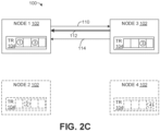
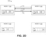
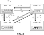
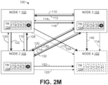
FIGS. 2A-2N illustrates another example of a system for establishing and maintaining a mesh network. -
FIG. 3 illustrates an example of a computing platform that can support a node of a mesh network. -
FIG. 4 illustrates an example of a system with a plurality of computing platforms for a plurality of nodes operating on an aircraft. -
FIG. 5 illustrates an example of a method for establishing and maintaining a mesh network. - The present disclosure relates to systems and methods for establishing and maintaining a mesh network amongst a plurality of nodes. The system includes one or more computing platforms that each initiates execution of a software application on each of the plurality of nodes in a non-deterministic order. Upon each node coming online (the software application completing the initiation process), the respective node broadcasts multicast identification messages to other nodes on the mesh network at a transient state rate. Each multicast identification message includes a unique identifier for the corresponding node (e.g., a network address and an open port number) and data characterizing a token register of the corresponding node.
- Additionally, in response to receipt of a multicast identification message, each node examines the corresponding token register to determine if a communication link has been established with the node that broadcast the respective multicast identification message, which node is referred to as a broadcasting node. If a communication link has not been established with the broadcasting node, each node that received the multicast identification message (which can be referred to as receiving nodes) establishes a communication link with the broadcasting node based on the unique identifier of the broadcasting node (e.g., the network address and open port). Additionally, in response to a subsequent multicast identification message from the broadcasting node, each receiving node adds the broadcasting node to the token register, along with an indication that a communication link has been established between the receiving node and the broadcasting node. Further, in response to each multicast identification message, each receiving node adds an indication of other nodes (if any) identified in the multicast identification message for which a communication link has not been established to the corresponding token register. Accordingly, the token register in each receiving node includes an indication of nodes identified in a multicast identification message, but where no (direct) communication link is established. This process continues until there is a communication link between each (online) node in the mesh network, such that the mesh network is a fully connected mesh network.
- Additionally, after a fully connected mesh network is established, each of the node on the mesh network reduces a rate of broadcasting the multicast identification messages from the transient state rate to a steady state rate to reduce network traffic. However, if at some point in the future a given node in the mesh network detects a failed communication link between the given node and a particular node, then the given node removes the particular node from the token register and changes the rate of the broadcast messages from the steady state rate to the transient state rate. By implementing the systems and methods described herein, a serverless mesh network without a single point of failure can be established and maintained. Furthermore, as noted, nodes on the mesh network can be initiated in a non-deterministic manner (e.g., an unpredictable order).
-
FIG. 1 illustrates an example of asystem 50 for establishing and maintaining a peer-to-peer (e.g., serverless) fully connected mesh network of N number ofnodes 52, where N is an integer greater than or equal to two. As used herein, the term "fully connected mesh network" indicates that eachnode 52 eventually has a direct connection to everyother node 52. - The N number of
nodes 52 can be representative of software services (e.g., an application and middleware) that execute on acomputing platform 54. AlthoughFIG. 1 illustrates one computing platform, it is understood that there could be multiple computing platforms. As one example, thesystem 50 could be implemented on an aircraft, wherein each of the N number ofnodes 52 represent different software services for controlling a different portion of the aircraft. - Each of the
nodes 52 can include a middleware application to facilitate communications betweennodes 52. The middleware can provide an isolated runtime environment for a software application executing thereon. In some examples, each of the N number ofnodes 52 can communicate with a standard communications protocol such as a communication protocol within the Transmission Control Protocol Internet Protocol (TCIP/IP) stack. More specifically, in some examples, thenodes 52 can communicate via the Transmission Control Protocol (TCP) or the User Datagram Protocol (UDP). - As used herein, the phrase "comes online" indicates that a
corresponding node 52 has completed execution of a startup process and is ready to communicate with other nodes on the mesh network. Similarly, the phrase "goes offline" indicates that the corresponding node cannot communicate with other nodes on the mesh network. Upon an initial startup of thecomputing platform 54, each of the N number ofnodes 52 are initiated. Moreover, at least two of theN number nodes 52 come online (e.g., complete a startup process) in a nondeterministic order. Stated differently, at least two of the nodes complete an initial startup sequence in an unpredictable order. As an example, on a first startup of thecomputing platform 54,node 2 may complete its startup process afternode 3 such thatnode 3 is online prior tonode 2. Further, on a second startup of the computing platform,node 2 may complete its startup process beforenode 3, such thatnode 2 is online prior tonode 3. The sequence of starting each of the N number ofnode 52 can be based, for example, on factors (e.g., network latency, operating system priorities and/or environmental factors) that may be outside of the control of thecomputing platform 54. - Each
node 52 stores atoken register 56 that tracksnodes 52 on the mesh network. More particularly, thetoken register 56 of eachnode 52 stores data that identifies information characterizing thenode 52 associated with thetoken register 56. Additionally, thetoken register 56 of eachnode 52 stores data fornodes 52 on the mesh network that have established a communication link with thenode 52 associated with thetoken register 56. Further, thetoken register 56 of eachnode 52 stores data fornodes 52 on the mesh network that have not established a communication link with thenode 52 associated with thetoken register 56 but have been identified in a multicast identification message from at least oneother node 52. Stated differently, for a givennode 52, thetoken register 56 for the given node identifies (i) the given node 52 (itself) (ii) eachother node 52 that the givennode 52 has established communication link with and (iii) eachnode 52 for which a communication link has not been established, but has been identified in a multicast identification message from anothernode 52. - From the time the
computing platform 54 is initialized, and until the mesh network is a fully connected mesh network, each of the N number ofnodes 52 operates in a transient state. In the transient state, each of the N number ofnodes 52, upon completing the corresponding startup procedure, broadcasts a multicast identification message to each active node in the mesh network at a transient state rate. Each of the (broadcasted) multicast identification messages includes a unique identifier ofnode 52 that broadcast the multicast identification message. The unique identifier can be a network address (IP address) and data characterizing an open port on thenode 52 that broadcast the multicast identification message. Eachnode 52 is configured such that a one-way communication link can be established with the given node through the open port identified in the broadcasted multicast identification messages. - As a given example (hereinafter, "the given example"), it is presumed that
node 1 comes online (e.g., completes the startup process) first,node 3 comes online second andnode 2 comes online third. In the given example, upon completing the startup process,node 1 broadcasts the multicast identification messages at the transient state rate. Initially, sincenode 1 is thefirst node 52 of the N number ofnodes 52 to come online, the multicast identification messages are not received bynode 3 ornode 2. - Continuing in the given example, upon
node 3 coming online (e.g., completes the startup process),node 3 receives the next multicast identification message broadcast bynode 1. In response to receiving the next multicast identification message,node 3 establishes (opens) a communication link fromnode 3 tonode 1. The communication link could be a TCP connection, a UDP connection or a connection using a different protocol. Additionally, in response to receipt of a subsequent multicast identification message broadcast bynode 3,node 1 updates the token register ofnode 1 to add an indication that a communication link has been established withnode 3. - Further, continuing with the given example,
node 3 also broadcasts the multicast identification messages at the transient state rate. Sincenode 2 is not yet online (e.g., has not completed the startup process)node 2 does not receive the multicast identification message fromnode 3. However, since at this point in the given example,node 1 is online,node 1 receives the multicast identification message. The multicast identification message fromnode 3 includes the unique identifier ofnode 3 and data characterizing thetoken register 56 ofnode 3. The unique identifier includes a network address (e.g., IP address) and an open port number for a communication link tonode 3. More generally, the unique identifier sent by a givennode 52 in a multicast identification message includes information for establishing a communication link with the given node. In response to receipt of the multicast identification message,node 1 opens a communication link withnode 3. Additionally, in a subsequent multicast identification message,node 1 provides data characterizing thetoken register 56 ofnode 1 tonode 3 as well as the unique identifier of node 1 (e.g., the IP address and open port number). In response to receipt of the data characterizing thetoken register 56 ofnode 1,node 3 updates thetoken register 56 ofnode 3. More particularly,node 3 adds an indication to thetoken register 56 that a communication link has been established withnode 1. - Continuing with the given example, at a subsequent time,
node 2 comes online. Upon coming online,node 2 broadcasts a multicast identification message that includes the unique identifier (e.g., IP address and open port number) ofnode 2. In the given example, it is presumed thatnode 1 receives the first multicast identification message fromnode 2, but thatnode 3 does not receive the multicast identification message. The multicast identification message may not be received by everyonline node 52 on the mesh network due to communication collisions and/or lost packets on the mesh network. Thus, in response to the multicast identification message,node 1 establishes a communication link withnode 2 and provides the data characterizing thetoken register 56 ofnode 1 tonode 2 in a subsequent multicast identification message. - In response to receipt of the data characterizing the
token register 56 ofnode 1,node 2 updates thetoken register 56 ofnode 2. In particular,node 2 adds an indication to thetoken register 56 that a communication link has been established withnode 1 and another indication fornode 3 indicating thatnode 3 is on the mesh network, but that a communication link has not been established withnode 3. That is, at this point of the given example, the token register ofnode 3 has two different indicators, a given indicator fornodes 52 in the mesh network that have established communication links with and another indicator for nodes for which a communication link has not been established, but for which another node (e.g., node 1) has identified as being a member of the mesh network. - Continuing with the given example, in a subsequent multicast identification message,
node 1 provides data characterizing an updated status of the token register ofnode 1 tonode 3. In response to the data characterizing the updatedtoken register 56 ofnode 1,node 2 updates thetoken register 56 ofnode 2. In particular,node 2 stores data in thetoken register 56 indicating thatnode 3 is a member of the mesh network, and that no communication link has been established withnode 2. - Continuing with the given example, each of the
N number nodes 52 continues to broadcast the multicast identification messages at the transient state rate. It is noted that the transient state rate may be the same or different fordifferent nodes 52. At some point, it is presumed that a multicast identification message broadcast bynode 3 is received atnode 2. In response,node 2 establishes a communication link withnode 3. Additionally, in a subsequent multicast identification message,node 2 provides the unique identifier of node 2 (e.g., the IP address and open port number) and data characterizing thetoken register 56 tonode 3. In response,node 3 establishes a communication link withnode 2 and in a subsequent multicast identification message, provides the unique identifier (e.g., IP address and open port number) ofnode 2 and data characterizing the token register ofnode 2 tonode 3. In response to the subsequent multicast identification message,node 2 modifies itstoken register 56 to record that a communication link is established withnode 3. Thus, at this point in the given example, direct, bi-directional communication is established between eachnode 52 of the mesh network. Accordingly, the mesh network is fully connected mesh network. - In subsequent multicast identification messages broadcast by each
node 52 of thesystem 50, the data characterizing the correspondingtoken register 56 identifies every node on the mesh network. Thus, after a predetermined amount of time (e.g., 5-10 seconds), the mesh network is considered to be in a steady state. In such a situation, after the predetermined amount of time, eachnode 52 can reduce the rate of broadcasting the multicast identification messages from the transient state rate to a steady state rate. As one example, in the steady state rate, eachnode 52 broadcasts the multicast identification messages at a rate that is at least one-half less than the transient state rate to reduce network traffic on the mesh network. Thus, if a givennode 52 broadcasts the multicast identification messages at a rate of one (1) message per second in the transient state rate, the given node would broadcast the multicast identification messages at a steady state rate of one (1) message every two (2) seconds or slower. - Continuing with the given example, it is presumed that at some point in time, after achieving the steady state,
node 3 goes offline (becomes disabled). In one example,node 3 may go offline, for example, due to a failure in software executing onnode 3. In another example,node 3 may go offline in a situation where an aircraft has sustained damage in a region where physical components of thesystem 50support node 3. In any such event, upon eithernode 1 or node 2 (the remaining function nodes 52) attempting to send a message to the offline node (node 2), the attempt fails. Such a failure could be detected, for example, with a lack of acknowledgement to the message sent. - Continuing with the given example, it is presumed that
node 2 detects thatnode 3 is not responding to messages. In such a situation,node 2 removesnode 3 fromnode 3'stoken register 56, andnode 2 switches back to the transient state, whereinnode 3 broadcasts multicast identification messages at the transient state rate that includes data characterizing thetoken register 56 in the updated state. In response to receipt of the multicast identification message,node 1 examines the data characterizing thetoken register 56 ofnode 2 and identifies thatnode 2 is missing. In response,node 1 can attempt to send a message tonode 3. Sincenode 3 is disabled in the given example, the attempt fails. In response,node 1 can removenode 3 from thetoken register 56 and return to the transient state, such that multicast identification messages are broadcast at the transient state rate. - Continuing with the given example, upon both remaining online nodes 52 (
node 1 and node 2) detecting that the corresponding token registers do not contain any other nodes in the mesh network, the mesh network returns to the steady state. In the given example, in the steady state, both nodes,nodes - By implementing the
system 50, the fully connected mesh network can be established quickly without employment of a server. Moreover, as noted, there is no requirement of any order in which thenodes 52 are activated and/or complete a startup process. That is, eachnode 52 on the mesh network can be brought online in any order and/or non-deterministically. Furthermore, thesystem 50 does not have a single point of failure. Rather, thesystem 50 is serverless, such that eachnode 52 can communicate withother nodes 52 without an intermediary system. Furthermore, the middleware can be configured such that messages from an application executing on the middleware are delayed until the intended recipient of the message (e.g., another application) comes online. -
FIGS. 2A-2N illustrate an example of asystem 100 for establishing and maintaining a fully connected mesh network amongst a plurality ofnodes 102. In the example illustrated, there are four (4)nodes 102. However, in other examples, there could be more orless nodes 102. Thenodes 102 can be employed to implement thenodes 52 ofFIG. 1 . Thenodes 102 can be representative of software services executing on a computing platform. Each software service can operate on a middleware that facilitates communication between thenodes 102. Eachnode 102 includes a token register 104 (labeled "TR" inFIGS. 2A-2N ). It is understood that throughoutFIGS. 2A-2N ,nodes 102 that are illustrated with solid lines (such asnode 1 andnode 2 inFIG. 2A ) are considered to be online (completed a startup process). Moreover, throughout the example illustrated inFIGS. 2A-2N ,nodes 102 with dashed lines (such asnode 2 andnode 4 ofFIG. 2A ) are considered to be offline (e.g., disabled and/or not completed a startup process). - Each
token register 104 includes an identification of thecorresponding node 102, and a given indication for nodes 102 (if any) within the mesh network with which thecorresponding node 102 has established a communication link. Additionally, eachtoken register 104 includes another indication for nodes (if any) within the mesh network that have been identified by anothernode 102, but where a communication link is not established. - In
FIG. 2A , it is presumed that the network is in a transient state. In particular, as noted, inFIG. 2A it presumed thatnode nodes FIG. 2A ,node 1 broadcasts a multicast identification message, as indicated by anarrow 110. Sincenode 2 andnode 4 are offline,node 3 receives themulticast identification message 110. Themulticast identification message 110 can include a unique identifier (e.g., an IP address and an open port number) and a token register for thenode 102 broadcasting themulticast identification message 110. In response to themulticast identification message 110, as illustrated inFIG. 2B ,node 3 establishes a communication link withnode 1 that is indicated by anarrow 112 on the open port identified in the multicast identification message fromnode 1. - As illustrated in
FIG. 2C , in a nextmulticast identification message 110 broadcast bynode 3 indicated by anarrow 114 includes data characterizing thetoken register 104 ofnode 3. Sincenode 3 established thecommunication link 112 withnode 1 andnode 3 andnode 1 received the data characterizing thetoken register 104 ofnode 3,node 1 addsnode 3 to thetoken register 104 ofnode 1. More particularly,node 1 addsnode 3 to thetoken register 104 along with the given indication that acommunication link 112 has been established withnode 3. As illustrated inFIG. 2D ,node 1 establishes a communication link withnode 3 on the open port ofnode 3 indicated by anarrow 116. Additionally, in a subsequentmulticast identification message 110,node 1 provides data characterizing thetoken register 104 ofnode 1, which identifiesnode 1 andnode 3. In response,node 3 addsnode 1 to thetoken register 104 ofnode 3 along with a given indication that communication link has been established withnode 1. - Furthermore, in
FIG. 2D , direct, bi-directional communication is established between eachnode 102 that is online. Accordingly, in an example where noadditional nodes 102 come online within a threshold time (e.g., 5-10 seconds), the resultant mesh network is a fully connected mesh network between twonodes 102. Thus, the mesh network is in the steady state, and in such a situation,node 1 andnode 3 reduce a rate of broadcasting the multicast identification messages from a transient state rate to a steady state rate. However, inFIG. 2E it is presumed thatnode 2 comes online causingnode 1 andnode 3 to return to the transient state. - More particularly, in
FIG. 2E , uponnode 2 coming online,node 2 broadcasts a multicast identification message, as indicated by anarrow 120, that includes the unique identifier (e.g., IP address and open port number) and data characterizing thetoken register 104 ofFIG. 2 . In response,node 1 establishes a communication link withnode 2 as indicated by anarrow 122. As illustrated inFIG. 2F , a subsequent multicast identification message 110 (also illustrated inFIG. 2A ) broadcast bynode 1 provides data characterizing thetoken register 104 ofnode 1. It is noted that throughoutFIGS. 2A-2N , the same reference numbers are employed with different arrows to indicate different endpoints for the same multicast identification message. For example, themulticast identification message 110 is broadcast bynode 1 to bothnode 3 andnode 2. - In response to the multicast identification message broadcast 110 by
node 1,node 2 modifies itstoken register 104. More particularly,node 2 addsnode 1 to thetoken register 104 ofnode 2 along with the given indication that thecommunication link 122 has been established withnode 1. Additionally,node 2 addsnode 3 to thetoken register 104 ofnode 2 along with another indication that a communication link has not been established withnode 3. As illustrated inFIG. 2E ,nodes 102 on the mesh network for which a communication link has not been established are represented intoken registers 104 with inverted coloring, as indicated byreference number 126. - In
FIG. 2F , in response to themulticast identification message 110 fromnode 1,node 2 establishes a communication link withnode 1, as indicated by anarrow 128. Additionally, in a subsequentmulticast identification message 120 broadcast bynode 2,node 2 provides data characterizing thetoken register 104 ofnode 2. In this situation, it is presumed thatnode 3 does not receive this particular multicast identification message. In response,node 1 addsnode 2 to thetoken register 104 ofnode 1 along with the given indication that thecommunication link 122 has been established withnode 2. Additionally, a subsequentmulticast identification message 110 fromnode 1 with the data characterizing thetoken register 104 ofnode 1 is received atnode 3. In response,node 3 addsnode 2 to thetoken register 104 along with the other indication that a communication link is not established withnode 2. - In
FIG. 2G , a subsequentmulticast identification message 120 broadcast bynode 2 is received atnode 3. In response,node 3 establishes a communication link withnode 2 on the open port ofnode 2, as indicated by anarrow 130. Additionally, in a subsequentmulticast identification message 114 broadcast bynode 3,node 3 provides data characterizing thetoken register 104 ofnode 3 to node 2 (and node 1). In response, since thecommunication link 130 fromnode 3 tonode 2 is established,node 2 changes thetoken register 104 ofnode 2 to indicate that thecommunication link 130 is established withnode 3. - Further, as illustrated in
FIG. 2H , in further response to themulticast identification message 114 broadcast bynode 3,node 2 establishes a communication link withnode 3 on the open port ofnode 3, indicated by anarrow 132. Further, in a subsequentmulticast identification message 120,node 2 broadcasts thetoken register 104 to node 3 (and node 1). Since thecommunication link 132 is established fromnode 2 tonode 3, in response,node 3 changes thetoken register 104 ofnode 3 to indicate that thecommunication link 132 is established withnode 2. - Moreover, similar to the situation illustrated in
FIG. 2D , inFIG. 2H , direct, bi-directional communication is established between eachnode 102 that is online. Accordingly, in an example where noadditional nodes 102 come online within a threshold time (e.g., 5-10 seconds), the resultant mesh network is a fully connected mesh network between three (3)nodes 102. Thus, the mesh network is in the steady state, and in such asituation node 1,node 2 andnode 3 reduce a rate of broadcasting the multicast identification messages from the transient state rate to the steady state rate. However, inFIG. 2I it is presumed thatnode 4 comes online causingnode 1,node 2 andnode 3 to return to the transient state. - More particularly, in
FIG. 21I , uponnode 4 coming online, as indicated by anarrow 140,node 4 broadcasts a multicast identification message that includes the unique identifier (e.g., IP address and open port number) and data characterizing thetoken register 104 ofnode 3. In the example illustrated inFIG. 2I , it is presumed thatnode 3 receives the multicast identification message fromnode 4, and thatnode 1 andnode 2 do not receive themulticast identification message 140 fromnode 4. In response,node 3 establishes a communication link withnode 4 as indicated by anarrow 142. As illustrated inFIG. 2I , in a subsequent multicast identification message 114 (also illustrated inFIG. 2A ),node 3 provides data characterizing thetoken register 104 ofnode 3. In response,node 4 modifies itstoken register 104. More particularly,node 2 addsnode 3 to thetoken register 104 ofnode 2 along with the given indication that thecommunication link 142 has been established withnode 4. Additionally,node 4 addsnode 1 andnode 2 to thetoken register 104 along with the other indication that a communication link has not been established withnode 1 ornode 2. Further,node 1 andnode 2 each modify their corresponding token registers 104 to add an indication thatnode 4 is a node on the mesh network, and that a communication link withnode 4 has not been established. - As illustrated by
FIG. 2J , a subsequentmulticast identification message 114 is received bynode 4, and in response,node 4 opens a communication link, indicated by anarrow 144 withnode 4. Moreover, a subsequentmulticast identification message 140 broadcast bynode 4 is received bynode 2 andnode 3, and not bynode 1. In response,node 3 modifies itstoken register 104 to indicate thecommunication link 144 has been established withnode 4. Additionally, in a manner described herein,node 2 establishes a communication link indicated by anarrow 150 on the open port ofnode 4 identified in themulticast identification message 140 andnode 2 broadcasts a subsequentmulticast identification message 120. In response to themulticast identification message 120 fromnode 2 since thecommunication link 150 is established fromnode 2 tonode 4,node 4 modifies itstoken register 104 to include the given indication that thecommunication link 150 has been established tonode 2. - Further still, in response to the
multicast identification message 120 fromnode 2,node 4 establishes a communication link, indicated by anarrow 152 withnode 2. Moreover, in response to a subsequentmulticast identification message 140 broadcast fromnode 4,node 2 modifies itstoken register 104 to include the given indication that thecommunication link 154 is established withnode 4. - As illustrated in
FIG. 2K , a subsequentmulticast identification message 140 broadcast bynode 4 is received bynode 1,node 2,node 3 andnode 4. In response,node 1 opens a communication link indicated by anarrow 154 withnode 4. Additionally, in response to receipt of a subsequentmulticast identification message 110 fromnode 1,node 4 modifies itstoken register 104 to include the given indication that thecommunication link 154 has been established withnode 1. Additionally, in response to the subsequentmulticast identification message 110 broadcast bynode 1, which is received at node 4 (as well asnode 2 and node 3). In response,node 4 opens a communication link indicated by anarrow 156 on the open port ofnode 4. In response to a subsequentmulticast identification message 140 broadcast bynode 4,node 1 modifies itstoken register 104 to include the given indication that thecommunication link 154 has been established withnode 4. - Moreover, similar to the situation illustrated in
FIGS. 2D and2H , inFIG. 2K direct, bi-directional communication is established between eachnode 102 that is online. Accordingly, in an example where noadditional nodes 102 come online within a threshold time (e.g., 5-10 seconds), the resultant mesh network is a fully connected mesh network between three (3)nodes 102. Thus, the mesh network is in the steady state, and in such asituation node 1,node 2,node 3 andnode 4 reduce a rate of broadcasting the multicast identification messages from the transient state rate to the steady state rate. - Further, in
FIG. 2L , it is presumed thatnode 4 goes offline in a non-determinate manner. As some examples,node 4 may go offline due to a software crash. In other examples,node 4 may go offline due to a hardware failure, such as damage to an aircraft carrying hardware fornode 4. In such a situation, multicast identification messages that are broadcast bynode 1,node 2 andnode 3, are not received bynode 4, as indicated by the dashed lines at 110, 114 and 152. Additionally, at some point,node 1 attempts to communicate withnode 4 via thecommunication link 154. Further,node 2 attempts to communicate withnode 4 via thecommunication link 152 andnode 3 attempts to communication withnode 4 via thecommunication link 142. Sincenode 4 is offline, each of the communication links 142, 152 and 154 are severed, as indicated by the dashedlines node 1,node 2 andnode 3 switch back to the transient mode, increasing the rate of broadcast of the multicast identification messages from the steady-state rate to the transient state rate. - As illustrated in
FIG. 2M , upon detecting thatnode 4 is offline,node 1,node 2 andnode 3 modify their respective token registers 104 to indicate thatnode 4 is a node on the mesh network, but that a communication link has not been established withnode 4. Further, after a predetermined amount of time (e.g., 5-10 seconds), as illustrated inFIG. 2N ,node 1,node 2 andnode 3 modify their respective token registers 104 to removenode 4 from the mesh network. Additionally, in an example where noadditional nodes 102 come online within a threshold time (e.g., 5-10 seconds), the resultant mesh network is a fully connected mesh network between three (3)nodes 102. Thus, the mesh network is in the steady state, and in such a situation,node 1,node 2 andnode 3 reduce a rate of broadcasting the multicast identification messages from the transient state rate to the steady state rate. - By employing the
system 100 ofFIGS. 2A-2N , each of thenodes 102 can be brought online and/or go offline in a non-deterministic order. Moreover, the middleware that facilitates communication of thenodes 102 can delay messages until each correspondingtoken register 104 indicates that a communication link has been established. In this manner, delays due to re-sending of messages and/or collisions on the mesh network can be curtailed. Furthermore, as demonstrated, thesystem 100 is serverless, such that no single point of failure of thesystem 100 exists. In fact, as demonstrated inFIGS. 2M-2N , eachnode 102 is configured to take remedial action in response to detecting anothernode 102 going offline. -
FIG. 3 illustrates an example of acomputing platform 200 that can support N number ofnodes 202, where N is an integer greater than or equal to one (1), such as thenodes 52 ofFIG. 1 and/or 102 ofFIGS. 2A-2N . Thecomputing platform 200 includeshardware 204. In some examples, thehardware 204 includes a non-transitory memory (e.g., volatile memory and/or non-volatile memory) for storing machine readable instructions and a processing unit (e.g., one or more processor cores) for accessing the memory and executing the machine-readable instructions. In some examples, the memory can be implemented as a hard disk drive, a solid-state drive, flash memory, random access memory, or any combination thereof. In other examples, thehardware 204 can include a microcontroller with instructions embedded therein. Further, in other examples, thehardware 204 includes an application specific integrated circuit (ASIC) chip. Thehardware 204 can also include an interface for communicating with other computing platforms, such as an Ethernet interface, a Wi-Fi interface, a Bluetooth interface, etc. - The
computing platform 200 can include anoperating system 206 that executes on thehardware 204. Theoperating system 206 can manage thehardware 204 and software resources and can provide common services for computer programs. Further, N number of instances of a middleware 208 (e.g., application software) can execute on theoperating system 206. Each of the N number of instances ofmiddleware 208 can be implemented on acorresponding node 202. Themiddleware 208 can facilitate communication between N number ofapplications 210, wherein eachnode 202 includes an application. More particularly, each instance ofmiddleware 208 can direct network communications (e.g., TCP and/or UDP packets) from oneapplication 210 to another, including situations where the two such applications are executing on separate computing platforms. Further, eachmiddleware 208 instance can delay requests by acorresponding application 210 for communication with another application until a node corresponding to the application comes online. That is, themiddleware 208 can prevent attempts by a givenapplication 210 to communicate with an offline application. In some examples, the N number of instances ofmiddleware 208 can provide an isolated runtime environment for thecorresponding application 210. -
FIG. 4 illustrates an example of asystem 250 that could be employed to implement thesystem 50 ofFIG. 1 and/or thesystem 100 ofFIGS. 2A-2N . Moreover, thesystem 250 includes three (3)computing platforms 252. Eachcomputing platform 252 can be representative of an instance of thecomputing platform 200 ofFIG. 3 . Thesystem 250 is provided as an example of software that could execute on a combat rated aircraft. - The
system 250 includes nodes executing on each of thecomputing platforms 252. Each node could be representative of an instance of anode 52 ofFIG. 1 and/or anode 102 ofFIGS. 2A-2N . In the example illustrated inFIG. 4 ,computing platform 1 includes anavigation node 260 and acontrols node 262. Thenavigation node 260 can include, for example, software for controlling a navigation system of the aircraft. Thecontrols node 262 can represent software for pilot controls of the aircraft. -
Computing platform 2 can include, for example, alanding gear node 264 that can be representative of software for controlling landing gear of the aircraft. Further,computing platform 3 can include aweapons node 266 for controlling operations of weapons systems for the aircraft. Each of thenavigation node 260, thecontrols node 262, thelanding gear node 264 and theweapons node 266 can be brought online or offline in a non-deterministic manner, as described herein. Moreover, as illustrated, a bi-directional communication links 270 (which can represent two one-way communication links) connect each node in thesystem 250 to every other node in thesystem 250. In this manner, thesystem 250 operates a fully-connected mesh network. Additionally, the resultant mesh network of thesystem 250 is serverless, such that thesystem 250 does not have a single point of failure. -
FIG. 5 illustrates an example of amethod 300 for establishing and maintaining a mesh network amongst a plurality of nodes operating on a computing platform. Themethod 300 can be executed by a given node (e.g., anode 52 ofFIG. 1 and/or anode 102 ofFIGS. 2A-2N ). - At 310, the given node initializes an application executing thereon, such that the given node is brought online. At 315, the node broadcasts multicast identification messages at a transient state rate. At 320, the node receives a multicast identification message broadcast by another node on the mesh network.
- At 325, a determination is made as to whether a communication link has been established with the other node. If the determination at 325 is negative (e.g., NO), the
method 300 proceeds to 330. If the determination at 325 is positive (e.g., YES), themethod 300 proceeds to 335. At 330, the given node establishes a communication link with the other node that broadcast the multicast identification message at a communication port identified in the multicast identification message, and the method returns to 315. - At 335, a determination is made as to whether a node or multiple nodes are to be added to a token register of the given node. The determination can be based, for example, on a determination that the other node which broadcasted the multicast identification message is not in the token register of the given node and/or a third node not in the token register of the given node is identified in the multicast identification message broadcast by the other node. If the determination at 335 is positive (e.g., YES), the
method 300 proceeds to 340. If the determination at 335 is negative (e.g., NO), themethod 300 proceeds to 345. At 340, the given node modifies its token register based on the determination at 335. In particular, the token register at 340 records a given indication for each node of the mesh network that the given node has established communication with and another indication of each node on the mesh network for which communication has not been established, and themethod 300 returns to 315. - At 345, another determination is made as to whether the mesh network has achieved a steady state. The determination at 345 can be based, for example, on an amount of time lapse since the token register of the given node was modified in response to a multicast identification message. If the determination at 345 is negative (e.g., NO), the
method 300 can return to 315. If the determination at 345 is positive (e.g., YES), themethod 300 proceeds to 350. At 350, the given node reduces the broadcasting rate of the multicast identification messages to a steady state rate (from the transient state rate). - What have been described above are examples. It is, of course, not possible to describe every conceivable combination of components or methodologies, but one of ordinary skill in the art will recognize that many further combinations and permutations are possible. Accordingly, the disclosure is intended to embrace all such alterations, modifications, and variations that fall within the scope of the appended claims. As used herein, the term "includes" means includes but not limited to, the term "including" means including but not limited to. The term "based on" means based at least in part on. Additionally, where the disclosure or claims recite "a," "an," "a first," or "another" element, or the equivalent thereof, it should be interpreted to include one or more than one such element, neither requiring nor excluding two or more such elements.
Claims (10)
- A system (100) for establishing a mesh networkcomprising: one or more computing platforms that:
initiates execution of a software application for each of a plurality of nodes (102) executing on the one or more computing platforms,wherein each of the plurality of nodes (102):establishes a communication link in the mesh network with another node of the plurality of nodes (102) in response to a multicast identification message from the other node;records, in a token register (104), a given indication of each node in the plurality of nodes (102) for which a communication link is established and another indication of each node of the plurality of nodes (102) that is identified in one or more multicast identification messages with which a communication link is not established;broadcasts multicast identification messages on the mesh network in response to the initiation of the respective node, wherein a given multicast identification message from the respective node includes a given identifier for each node of the plurality of nodes (102) for which the respective node established a communication link and another identifier for each node identified in the one or more multicast identification messages with which the respective node has not established a communication link;establishes a communication link with each node of the plurality of nodes for which the respective node has not established a communication link based on the other identifier included in the given multicast identification message from the respective node;reduces a rate of broadcasting the multicast identification messages from a transient state rate to a steady state rate in response to establishing a communication link with each of the plurality of nodes (102);detects a failed communication link between the respective node and a particular node;removes the particular node from the token register; andchanges the rate of the broadcasting the multicast identification messages from the steady state rate to the transient state rate. - The system of claim 1, wherein at least two of the plurality of nodes are initiated in a non-deterministic order.
- The system of claim 1, wherein the multicast identification message provided by each respective node identifies an open communication port on the respective node.
- The system of claim 1, wherein the one or more computing platforms comprises a middleware that facilitates communication between the plurality of nodes (102) via the mesh network.
- The system of claim 1, wherein each of the plurality of nodes (102) operate in an isolated runtime environment.
- A method for establishing a mesh network, comprising:initiating, by one or more computing platforms, execution of a software application for each of a plurality of nodes (102) executing on the one or more computing platforms,establishing, by each of the plurality of nodes (102), a communication link in the mesh network with another node of the plurality of nodes (102) in response to a multicast identification message from the other node;recording in a token register (104), by each of the plurality of nodes (102), a given indication of each node in the plurality of nodes (102) for which a communication link is established and another indication of each node of the plurality of nodes (102) that is identified in one or more multicast identification messages with which a communication link is not established;broadcasting, by each of the plurality of nodes (102), multicast identification messages on the mesh network in response to the initiation of the respective node, wherein a given multicast identification message from the respective node includes a given identifier for each node of the plurality of nodes (102) for which the respective node established a communication link and another identifier for each node identified in the one or more multicast identification messages with which the respective node has not established a communication link;establishing, by each of the plurality of nodes (102), a communication link with each node of the plurality of nodes for which the respective node has not established a communication link based on the other identifier included in the given multicast identification message from the respective node;reducing, by each of the plurality of nodes (102), a rate of broadcasting the multicast identification messages from a transient state rate to a steady state rate in response to establishing a communication link with each of the plurality of nodes (102);detecting, by each of the plurality of nodes (102), a failed communication link between the respective node and a particular node;removing, by each of the plurality of nodes (102), the particular node from the token register; andchanging, by each of the plurality of nodes (102), the rate of the broadcasting the multicast identification messages from the steady state rate to the transient state rate.
- The method of claim 6, wherein at least two of the plurality of nodes (102) are initiated in a non-deterministic order.
- The method of claim 6, wherein the multicast identification message provided by each respective node identifies an open communication port on the respective node.
- The method of claim 6, wherein the one or more computing platforms comprises a middleware that facilitates communication between the plurality of nodes (102) via the mesh network.
- The method of claim 6, wherein each of the plurality of nodes (102) operate in an isolated runtime environment.
Applications Claiming Priority (2)
| Application Number | Priority Date | Filing Date | Title |
|---|---|---|---|
| US16/250,927 US10805146B2 (en) | 2019-01-17 | 2019-01-17 | Mesh network |
| PCT/US2019/065505 WO2020149965A1 (en) | 2019-01-17 | 2019-12-10 | Mesh network |
Publications (2)
| Publication Number | Publication Date |
|---|---|
| EP3887955A1 EP3887955A1 (en) | 2021-10-06 |
| EP3887955B1 true EP3887955B1 (en) | 2025-04-16 |
Family
ID=69024752
Family Applications (1)
| Application Number | Title | Priority Date | Filing Date |
|---|---|---|---|
| EP19828527.2A Active EP3887955B1 (en) | 2019-01-17 | 2019-12-10 | Mesh network |
Country Status (5)
| Country | Link |
|---|---|
| US (1) | US10805146B2 (en) |
| EP (1) | EP3887955B1 (en) |
| JP (1) | JP7315679B2 (en) |
| KR (1) | KR102631618B1 (en) |
| WO (1) | WO2020149965A1 (en) |
Families Citing this family (5)
| Publication number | Priority date | Publication date | Assignee | Title |
|---|---|---|---|---|
| US11257184B1 (en) | 2018-02-21 | 2022-02-22 | Northrop Grumman Systems Corporation | Image scaler |
| US11157003B1 (en) | 2018-04-05 | 2021-10-26 | Northrop Grumman Systems Corporation | Software framework for autonomous system |
| US11392284B1 (en) | 2018-11-01 | 2022-07-19 | Northrop Grumman Systems Corporation | System and method for implementing a dynamically stylable open graphics library |
| US11089118B1 (en) * | 2020-06-19 | 2021-08-10 | Northrop Grumman Systems Corporation | Interlock for mesh network |
| US12182581B2 (en) * | 2022-11-02 | 2024-12-31 | Pure Storage, Inc. | Prioritized deployment of nodes in a distributed storage system |
Family Cites Families (36)
| Publication number | Priority date | Publication date | Assignee | Title |
|---|---|---|---|---|
| US5909577A (en) | 1994-04-18 | 1999-06-01 | Lucent Technologies Inc. | Determining dynamic properties of programs |
| US5872909A (en) | 1995-01-24 | 1999-02-16 | Wind River Systems, Inc. | Logic analyzer for software |
| US6038031A (en) | 1997-07-28 | 2000-03-14 | 3Dlabs, Ltd | 3D graphics object copying with reduced edge artifacts |
| US6976243B2 (en) | 1999-10-05 | 2005-12-13 | Borland Software Coporation | Method and system for developing source code and displaying linked elements found within the source code |
| US20030023956A1 (en) | 2000-02-14 | 2003-01-30 | Adi Dulberg | Embedded device monitoring agent |
| AU2002234258A1 (en) | 2001-01-22 | 2002-07-30 | Sun Microsystems, Inc. | Peer-to-peer network computing platform |
| US7143343B2 (en) | 2002-04-11 | 2006-11-28 | International Business Machines Corporation | Dynamic creation of an application's XML document type definition (DTD) |
| US6927778B2 (en) | 2002-05-16 | 2005-08-09 | Ati Technologies, Inc. | System for alpha blending and method thereof |
| GB0406104D0 (en) | 2004-03-17 | 2004-04-21 | Koninkl Philips Electronics Nv | Connecting devices to a peer-to-peer network |
| JP2007536634A (en) | 2004-05-04 | 2007-12-13 | フィッシャー−ローズマウント・システムズ・インコーポレーテッド | Service-oriented architecture for process control systems |
| US7623516B2 (en) | 2004-06-29 | 2009-11-24 | Damaka, Inc. | System and method for deterministic routing in a peer-to-peer hybrid communications network |
| US8086963B2 (en) | 2005-05-19 | 2011-12-27 | Microsoft Corporation | Inheritance model between masters, layouts and slides |
| US7664107B2 (en) | 2006-04-05 | 2010-02-16 | Microsoft Corporation | Self-stabilizing and fast-convergent structured peer-to-peer overlays |
| US8659654B2 (en) | 2006-10-11 | 2014-02-25 | Microsoft Corporation | Image verification with tiered tolerance |
| US8136124B2 (en) | 2007-01-18 | 2012-03-13 | Oracle America, Inc. | Method and apparatus for synthesizing hardware counters from performance sampling |
| US8719798B2 (en) | 2007-08-01 | 2014-05-06 | Sony Corporation | System and method for software logging |
| US7996765B1 (en) | 2007-09-07 | 2011-08-09 | Adobe Systems Incorporated | System and method for style sheet language coding that maintains a desired relationship between display elements |
| US20090145172A1 (en) | 2007-12-10 | 2009-06-11 | Bsh Home Appliances Corporation | Washing machine with ultraviolet protection cycle |
| JP2009260594A (en) * | 2008-04-16 | 2009-11-05 | Meidensha Corp | Data communication method |
| US9198017B2 (en) * | 2008-05-19 | 2015-11-24 | Qualcomm Incorporated | Infrastructure assisted discovery in a wireless peer-to-peer network |
| GB0823701D0 (en) | 2008-12-31 | 2009-02-04 | Symbian Software Ltd | Fast data entry |
| US7990897B2 (en) * | 2009-03-11 | 2011-08-02 | Sony Corporation | Method and apparatus for a wireless home mesh network with network topology visualizer |
| US10553001B2 (en) | 2009-11-20 | 2020-02-04 | Adobe Inc. | Master page overlay |
| US20110216059A1 (en) | 2010-03-03 | 2011-09-08 | Raytheon Company | Systems and methods for generating real-time three-dimensional graphics in an area of interest |
| US20120011491A1 (en) | 2010-07-06 | 2012-01-12 | Adi Eldar | Efficient recording and replaying of the execution path of a computer program |
| US8863256B1 (en) * | 2011-01-14 | 2014-10-14 | Cisco Technology, Inc. | System and method for enabling secure transactions using flexible identity management in a vehicular environment |
| JP6113443B2 (en) * | 2012-09-14 | 2017-04-12 | 株式会社日立国際電気 | Communication system and communication method thereof |
| US9361202B2 (en) | 2013-07-18 | 2016-06-07 | International Business Machines Corporation | Filtering system noises in parallel computer systems during thread synchronization |
| US9501346B2 (en) | 2014-01-21 | 2016-11-22 | Oracle International Corporation | Fine and coarse granularity logging handler |
| JP6031535B2 (en) | 2014-02-10 | 2016-11-24 | ネイバー コーポレーションNAVER Corporation | Site management method and system for supporting site production using various types of cards |
| US10430169B2 (en) | 2014-05-30 | 2019-10-01 | Apple Inc. | Language, function library, and compiler for graphical and non-graphical computation on a graphical processor unit |
| US9600594B2 (en) | 2014-10-09 | 2017-03-21 | Wrap Media, LLC | Card based package for distributing electronic media and services |
| US20170329730A1 (en) | 2016-05-12 | 2017-11-16 | Wipro Limited | Method and unit for handling interrupts in a system |
| US10689109B2 (en) * | 2016-10-13 | 2020-06-23 | Dynetics, Inc. | Interceptor unmanned aerial system |
| EP3574681B1 (en) * | 2017-01-25 | 2023-09-20 | Airties SAS | Island topologies and routing in hybrid mesh networks |
| US20190246289A1 (en) * | 2018-02-08 | 2019-08-08 | Mediatek Singapore Pte. Ltd. | System And Method To Form An Optimized Repeater Network |
-
2019
- 2019-01-17 US US16/250,927 patent/US10805146B2/en active Active
- 2019-12-10 JP JP2021540893A patent/JP7315679B2/en active Active
- 2019-12-10 KR KR1020217022711A patent/KR102631618B1/en active Active
- 2019-12-10 EP EP19828527.2A patent/EP3887955B1/en active Active
- 2019-12-10 WO PCT/US2019/065505 patent/WO2020149965A1/en not_active Ceased
Non-Patent Citations (2)
| Title |
|---|
| KELSEY SILICON LABS R: "Mesh Link Establishment; draft-ietf-6lo-mesh-link-establishment-00.txt", MESH LINK ESTABLISHMENT; DRAFT-IETF-6LO-MESH-LINK-ESTABLISHMENT-00.TXT, INTERNET ENGINEERING TASK FORCE, IETF; STANDARDWORKINGDRAFT, INTERNET SOCIETY (ISOC) 4, RUE DES FALAISES CH- 1205 GENEVA, SWITZERLAND, 1 December 2015 (2015-12-01), pages 1 - 19, XP015110069 * |
| SISTU SRIKANTH: "Performance evaluation of thread-based wireless mesh networks for commercial lighting - Master Thesis", 1 July 2018 (2018-07-01), pages 1 - 65, XP093137286, Retrieved from the Internet <URL:https://pure.tue.nl/ws/portalfiles/portal/110034671/Sistu_1033098.pdf> [retrieved on 20240304] * |
Also Published As
| Publication number | Publication date |
|---|---|
| WO2020149965A1 (en) | 2020-07-23 |
| US10805146B2 (en) | 2020-10-13 |
| KR20210104851A (en) | 2021-08-25 |
| US20200235987A1 (en) | 2020-07-23 |
| JP7315679B2 (en) | 2023-07-26 |
| JP2022517266A (en) | 2022-03-07 |
| EP3887955A1 (en) | 2021-10-06 |
| KR102631618B1 (en) | 2024-02-01 |
Similar Documents
| Publication | Publication Date | Title |
|---|---|---|
| US10805146B2 (en) | Mesh network | |
| EP1543420B1 (en) | Consistent message ordering for semi-active and passive replication | |
| EP3396883B1 (en) | Tcp ack data transmission method and related device | |
| CN1881945B (en) | Improved distributed kernel operating system | |
| KR20050065346A (en) | System and method for managing protocol network failures in a cluster system | |
| CN1881944B (en) | Improved Distributed Core Operating System | |
| US11985027B2 (en) | Systems and methods for seamless failover in branch deployments by superimposing clustering solution on VRRP | |
| KR102709540B1 (en) | System and method for transmitting message nbased on sdn | |
| US9942165B2 (en) | Method for transmitting data in a packet-oriented communications network and correspondingly configured user terminal in said communications network | |
| US8868782B2 (en) | System and methods for a managed application server restart | |
| CN116248775B (en) | Interaction methods, devices, electronic equipment, and storage media of DDS gateways | |
| CN108737265B (en) | Software defined wireless network system and management method thereof | |
| JP4415391B2 (en) | Method and apparatus for transmitting data to a network and method and apparatus for receiving data from a network | |
| CN113765711B (en) | Network equipment keep-alive method and device | |
| US11870672B2 (en) | Self-election processes in managed subnets implementing modified swim protocols | |
| KR102844626B1 (en) | Interlock of the mesh net | |
| US20220038387A1 (en) | In-vehicle communication system, relay device, and communication method | |
| US20080025302A1 (en) | Method and system for managing network ports | |
| US11153197B2 (en) | Protocol for data transfer between two nodes of partially connected limited network | |
| JP2010251911A (en) | Internode data response system | |
| JP2003348134A (en) | Communication path selecting system | |
| JP2022148220A (en) | Gate state confirmation system, gate state confirmation method, and communication device | |
| WO2024052981A1 (en) | Processing device, processing method, and program | |
| CN117979327A (en) | A disaster recovery system, method and device based on edge UPF backup group |
Legal Events
| Date | Code | Title | Description |
|---|---|---|---|
| STAA | Information on the status of an ep patent application or granted ep patent |
Free format text: STATUS: UNKNOWN |
|
| STAA | Information on the status of an ep patent application or granted ep patent |
Free format text: STATUS: THE INTERNATIONAL PUBLICATION HAS BEEN MADE |
|
| PUAI | Public reference made under article 153(3) epc to a published international application that has entered the european phase |
Free format text: ORIGINAL CODE: 0009012 |
|
| STAA | Information on the status of an ep patent application or granted ep patent |
Free format text: STATUS: REQUEST FOR EXAMINATION WAS MADE |
|
| 17P | Request for examination filed |
Effective date: 20210628 |
|
| AK | Designated contracting states |
Kind code of ref document: A1 Designated state(s): AL AT BE BG CH CY CZ DE DK EE ES FI FR GB GR HR HU IE IS IT LI LT LU LV MC MK MT NL NO PL PT RO RS SE SI SK SM TR |
|
| DAV | Request for validation of the european patent (deleted) | ||
| DAX | Request for extension of the european patent (deleted) | ||
| STAA | Information on the status of an ep patent application or granted ep patent |
Free format text: STATUS: EXAMINATION IS IN PROGRESS |
|
| 17Q | First examination report despatched |
Effective date: 20230322 |
|
| P01 | Opt-out of the competence of the unified patent court (upc) registered |
Effective date: 20230607 |
|
| GRAP | Despatch of communication of intention to grant a patent |
Free format text: ORIGINAL CODE: EPIDOSNIGR1 |
|
| STAA | Information on the status of an ep patent application or granted ep patent |
Free format text: STATUS: GRANT OF PATENT IS INTENDED |
|
| RIC1 | Information provided on ipc code assigned before grant |
Ipc: H04L 41/0659 20220101ALI20241007BHEP Ipc: H04L 67/12 20220101ALI20241007BHEP Ipc: H04L 45/02 20220101ALI20241007BHEP Ipc: H04W 40/24 20090101ALI20241007BHEP Ipc: G06F 15/173 20060101ALI20241007BHEP Ipc: G06F 9/54 20060101AFI20241007BHEP |
|
| INTG | Intention to grant announced |
Effective date: 20241112 |
|
| GRAS | Grant fee paid |
Free format text: ORIGINAL CODE: EPIDOSNIGR3 |
|
| GRAA | (expected) grant |
Free format text: ORIGINAL CODE: 0009210 |
|
| STAA | Information on the status of an ep patent application or granted ep patent |
Free format text: STATUS: THE PATENT HAS BEEN GRANTED |
|
| AK | Designated contracting states |
Kind code of ref document: B1 Designated state(s): AL AT BE BG CH CY CZ DE DK EE ES FI FR GB GR HR HU IE IS IT LI LT LU LV MC MK MT NL NO PL PT RO RS SE SI SK SM TR |
|
| REG | Reference to a national code |
Ref country code: GB Ref legal event code: FG4D |
|
| REG | Reference to a national code |
Ref country code: CH Ref legal event code: EP |
|
| REG | Reference to a national code |
Ref country code: IE Ref legal event code: FG4D |
|
| REG | Reference to a national code |
Ref country code: DE Ref legal event code: R096 Ref document number: 602019068774 Country of ref document: DE |
|
| REG | Reference to a national code |
Ref country code: NL Ref legal event code: MP Effective date: 20250416 |
|
| PG25 | Lapsed in a contracting state [announced via postgrant information from national office to epo] |
Ref country code: NL Free format text: LAPSE BECAUSE OF FAILURE TO SUBMIT A TRANSLATION OF THE DESCRIPTION OR TO PAY THE FEE WITHIN THE PRESCRIBED TIME-LIMIT Effective date: 20250416 |
|
| REG | Reference to a national code |
Ref country code: AT Ref legal event code: MK05 Ref document number: 1786216 Country of ref document: AT Kind code of ref document: T Effective date: 20250416 |
|
| PG25 | Lapsed in a contracting state [announced via postgrant information from national office to epo] |
Ref country code: PT Free format text: LAPSE BECAUSE OF FAILURE TO SUBMIT A TRANSLATION OF THE DESCRIPTION OR TO PAY THE FEE WITHIN THE PRESCRIBED TIME-LIMIT Effective date: 20250818 Ref country code: ES Free format text: LAPSE BECAUSE OF FAILURE TO SUBMIT A TRANSLATION OF THE DESCRIPTION OR TO PAY THE FEE WITHIN THE PRESCRIBED TIME-LIMIT Effective date: 20250416 Ref country code: FI Free format text: LAPSE BECAUSE OF FAILURE TO SUBMIT A TRANSLATION OF THE DESCRIPTION OR TO PAY THE FEE WITHIN THE PRESCRIBED TIME-LIMIT Effective date: 20250416 |
|
| REG | Reference to a national code |
Ref country code: LT Ref legal event code: MG9D |
|
| PG25 | Lapsed in a contracting state [announced via postgrant information from national office to epo] |
Ref country code: NO Free format text: LAPSE BECAUSE OF FAILURE TO SUBMIT A TRANSLATION OF THE DESCRIPTION OR TO PAY THE FEE WITHIN THE PRESCRIBED TIME-LIMIT Effective date: 20250716 Ref country code: GR Free format text: LAPSE BECAUSE OF FAILURE TO SUBMIT A TRANSLATION OF THE DESCRIPTION OR TO PAY THE FEE WITHIN THE PRESCRIBED TIME-LIMIT Effective date: 20250717 |
|
| PG25 | Lapsed in a contracting state [announced via postgrant information from national office to epo] |
Ref country code: PL Free format text: LAPSE BECAUSE OF FAILURE TO SUBMIT A TRANSLATION OF THE DESCRIPTION OR TO PAY THE FEE WITHIN THE PRESCRIBED TIME-LIMIT Effective date: 20250416 |
|
| PG25 | Lapsed in a contracting state [announced via postgrant information from national office to epo] |
Ref country code: BG Free format text: LAPSE BECAUSE OF FAILURE TO SUBMIT A TRANSLATION OF THE DESCRIPTION OR TO PAY THE FEE WITHIN THE PRESCRIBED TIME-LIMIT Effective date: 20250416 |
|
| PG25 | Lapsed in a contracting state [announced via postgrant information from national office to epo] |
Ref country code: HR Free format text: LAPSE BECAUSE OF FAILURE TO SUBMIT A TRANSLATION OF THE DESCRIPTION OR TO PAY THE FEE WITHIN THE PRESCRIBED TIME-LIMIT Effective date: 20250416 |
|
| PG25 | Lapsed in a contracting state [announced via postgrant information from national office to epo] |
Ref country code: AT Free format text: LAPSE BECAUSE OF FAILURE TO SUBMIT A TRANSLATION OF THE DESCRIPTION OR TO PAY THE FEE WITHIN THE PRESCRIBED TIME-LIMIT Effective date: 20250416 |
|
| PG25 | Lapsed in a contracting state [announced via postgrant information from national office to epo] |
Ref country code: RS Free format text: LAPSE BECAUSE OF FAILURE TO SUBMIT A TRANSLATION OF THE DESCRIPTION OR TO PAY THE FEE WITHIN THE PRESCRIBED TIME-LIMIT Effective date: 20250716 |
|
| PG25 | Lapsed in a contracting state [announced via postgrant information from national office to epo] |
Ref country code: IS Free format text: LAPSE BECAUSE OF FAILURE TO SUBMIT A TRANSLATION OF THE DESCRIPTION OR TO PAY THE FEE WITHIN THE PRESCRIBED TIME-LIMIT Effective date: 20250816 |
|
| PG25 | Lapsed in a contracting state [announced via postgrant information from national office to epo] |
Ref country code: LV Free format text: LAPSE BECAUSE OF FAILURE TO SUBMIT A TRANSLATION OF THE DESCRIPTION OR TO PAY THE FEE WITHIN THE PRESCRIBED TIME-LIMIT Effective date: 20250416 |
|
| PGFP | Annual fee paid to national office [announced via postgrant information from national office to epo] |
Ref country code: DE Payment date: 20251211 Year of fee payment: 7 |
|
| PGFP | Annual fee paid to national office [announced via postgrant information from national office to epo] |
Ref country code: GB Payment date: 20251219 Year of fee payment: 7 |
|
| PG25 | Lapsed in a contracting state [announced via postgrant information from national office to epo] |
Ref country code: SM Free format text: LAPSE BECAUSE OF FAILURE TO SUBMIT A TRANSLATION OF THE DESCRIPTION OR TO PAY THE FEE WITHIN THE PRESCRIBED TIME-LIMIT Effective date: 20250416 Ref country code: DK Free format text: LAPSE BECAUSE OF FAILURE TO SUBMIT A TRANSLATION OF THE DESCRIPTION OR TO PAY THE FEE WITHIN THE PRESCRIBED TIME-LIMIT Effective date: 20250416 |
|
| PGFP | Annual fee paid to national office [announced via postgrant information from national office to epo] |
Ref country code: FR Payment date: 20251229 Year of fee payment: 7 |
|
| REG | Reference to a national code |
Ref country code: DE Ref legal event code: R097 Ref document number: 602019068774 Country of ref document: DE |
|
| PG25 | Lapsed in a contracting state [announced via postgrant information from national office to epo] |
Ref country code: CZ Free format text: LAPSE BECAUSE OF FAILURE TO SUBMIT A TRANSLATION OF THE DESCRIPTION OR TO PAY THE FEE WITHIN THE PRESCRIBED TIME-LIMIT Effective date: 20250416 |
|
| PG25 | Lapsed in a contracting state [announced via postgrant information from national office to epo] |
Ref country code: EE Free format text: LAPSE BECAUSE OF FAILURE TO SUBMIT A TRANSLATION OF THE DESCRIPTION OR TO PAY THE FEE WITHIN THE PRESCRIBED TIME-LIMIT Effective date: 20250416 |
|
| PG25 | Lapsed in a contracting state [announced via postgrant information from national office to epo] |
Ref country code: RO Free format text: LAPSE BECAUSE OF FAILURE TO SUBMIT A TRANSLATION OF THE DESCRIPTION OR TO PAY THE FEE WITHIN THE PRESCRIBED TIME-LIMIT Effective date: 20250416 Ref country code: SK Free format text: LAPSE BECAUSE OF FAILURE TO SUBMIT A TRANSLATION OF THE DESCRIPTION OR TO PAY THE FEE WITHIN THE PRESCRIBED TIME-LIMIT Effective date: 20250416 |
|
| PG25 | Lapsed in a contracting state [announced via postgrant information from national office to epo] |
Ref country code: IT Free format text: LAPSE BECAUSE OF FAILURE TO SUBMIT A TRANSLATION OF THE DESCRIPTION OR TO PAY THE FEE WITHIN THE PRESCRIBED TIME-LIMIT Effective date: 20250416 |
|
| PLBE | No opposition filed within time limit |
Free format text: ORIGINAL CODE: 0009261 |
|
| STAA | Information on the status of an ep patent application or granted ep patent |
Free format text: STATUS: NO OPPOSITION FILED WITHIN TIME LIMIT |
|
| REG | Reference to a national code |
Ref country code: CH Ref legal event code: L10 Free format text: ST27 STATUS EVENT CODE: U-0-0-L10-L00 (AS PROVIDED BY THE NATIONAL OFFICE) Effective date: 20260225 |
|
| 26N | No opposition filed |
Effective date: 20260119 |