EP3887243B1 - Retriever system for a marine equipment and method - Google Patents
Retriever system for a marine equipment and method Download PDFInfo
- Publication number
- EP3887243B1 EP3887243B1 EP19839658.2A EP19839658A EP3887243B1 EP 3887243 B1 EP3887243 B1 EP 3887243B1 EP 19839658 A EP19839658 A EP 19839658A EP 3887243 B1 EP3887243 B1 EP 3887243B1
- Authority
- EP
- European Patent Office
- Prior art keywords
- inflatable element
- hollow body
- inflating
- retriever
- cap
- Prior art date
- Legal status (The legal status is an assumption and is not a legal conclusion. Google has not performed a legal analysis and makes no representation as to the accuracy of the status listed.)
- Active
Links
Images


Classifications
-
- G—PHYSICS
- G01—MEASURING; TESTING
- G01V—GEOPHYSICS; GRAVITATIONAL MEASUREMENTS; DETECTING MASSES OR OBJECTS; TAGS
- G01V1/00—Seismology; Seismic or acoustic prospecting or detecting
- G01V1/38—Seismology; Seismic or acoustic prospecting or detecting specially adapted for water-covered areas
- G01V1/3817—Positioning of seismic devices
- G01V1/3826—Positioning of seismic devices dynamic steering, e.g. by paravanes or birds
-
- B—PERFORMING OPERATIONS; TRANSPORTING
- B63—SHIPS OR OTHER WATERBORNE VESSELS; RELATED EQUIPMENT
- B63B—SHIPS OR OTHER WATERBORNE VESSELS; EQUIPMENT FOR SHIPPING
- B63B22/00—Buoys
- B63B22/04—Fixations or other anchoring arrangements
-
- B—PERFORMING OPERATIONS; TRANSPORTING
- B63—SHIPS OR OTHER WATERBORNE VESSELS; RELATED EQUIPMENT
- B63B—SHIPS OR OTHER WATERBORNE VESSELS; EQUIPMENT FOR SHIPPING
- B63B21/00—Tying-up; Shifting, towing, or pushing equipment; Anchoring
- B63B21/56—Towing or pushing equipment
- B63B21/66—Equipment specially adapted for towing underwater objects or vessels, e.g. fairings for tow-cables
-
- B—PERFORMING OPERATIONS; TRANSPORTING
- B63—SHIPS OR OTHER WATERBORNE VESSELS; RELATED EQUIPMENT
- B63B—SHIPS OR OTHER WATERBORNE VESSELS; EQUIPMENT FOR SHIPPING
- B63B22/00—Buoys
- B63B22/04—Fixations or other anchoring arrangements
- B63B22/08—Fixations or other anchoring arrangements having means to release or urge to the surface a buoy on submergence thereof, e.g. to mark location of a sunken object
- B63B22/12—Fixations or other anchoring arrangements having means to release or urge to the surface a buoy on submergence thereof, e.g. to mark location of a sunken object the surfacing of the buoy being assisted by a gas released or generated on submergence of the buoy
-
- B—PERFORMING OPERATIONS; TRANSPORTING
- B63—SHIPS OR OTHER WATERBORNE VESSELS; RELATED EQUIPMENT
- B63B—SHIPS OR OTHER WATERBORNE VESSELS; EQUIPMENT FOR SHIPPING
- B63B22/00—Buoys
- B63B22/18—Buoys having means to control attitude or position, e.g. reaction surfaces or tether
- B63B22/20—Ballast means
-
- B—PERFORMING OPERATIONS; TRANSPORTING
- B63—SHIPS OR OTHER WATERBORNE VESSELS; RELATED EQUIPMENT
- B63B—SHIPS OR OTHER WATERBORNE VESSELS; EQUIPMENT FOR SHIPPING
- B63B2211/00—Applications
- B63B2211/02—Oceanography
-
- G—PHYSICS
- G01—MEASURING; TESTING
- G01V—GEOPHYSICS; GRAVITATIONAL MEASUREMENTS; DETECTING MASSES OR OBJECTS; TAGS
- G01V1/00—Seismology; Seismic or acoustic prospecting or detecting
- G01V1/38—Seismology; Seismic or acoustic prospecting or detecting specially adapted for water-covered areas
- G01V1/3817—Positioning of seismic devices
-
- G—PHYSICS
- G01—MEASURING; TESTING
- G01V—GEOPHYSICS; GRAVITATIONAL MEASUREMENTS; DETECTING MASSES OR OBJECTS; TAGS
- G01V1/00—Seismology; Seismic or acoustic prospecting or detecting
- G01V1/16—Receiving elements for seismic signals; Arrangements or adaptations of receiving elements
- G01V1/20—Arrangements of receiving elements, e.g. geophone pattern
- G01V1/201—Constructional details of seismic cables, e.g. streamers
- G01V2001/207—Buoyancy
Definitions
- Embodiments of the subject matter disclosed herein generally relate to methods and systems and, more particularly, to mechanisms and techniques for retrieving a marine equipment.
- Marine seismic data acquisition and processing generate a profile (image) of the geophysical structure (subsurface) under the seafloor.
- the operations of acquiring seismic data on site conventionally use networks of seismic sensors, like accelerometers, geophones or hydrophones.
- the hydrophones are distributed along cables in order to form linear acoustic antennas (also referred to as “streamers” or “seismic streamers”).
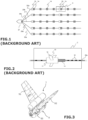
- a seismic vessel 21 tows the network of seismic streamers 20a to 20e.
- the hydrophones are referenced 16 in Figure 2 , which illustrates in detail the block referenced C in Figure 1 (i.e. a portion of the streamer referenced 20a).
- the seismic method is based on an analysis of reflected seismic waves.
- one or more submerged seismic sources are activated in order to propagate omnidirectional seismic wave trains.
- the pressure wave generated by the seismic source(s) passes through the column of water and propagates through the different layers of the seabed.
- the reflected seismic waves i.e. reflected acoustic signals
- These acoustic signals are processed and retransmitted by telemetry from the seismic streamers to the operator station situated on the seismic vessel, where the processing of the raw data is carried out (in an alternative solution, the seismic acoustic signals are stored for a later processing).
- Control of the positions of streamers lies in the implementation of navigation control devices (also referred to as "birds") (white squares referenced 10 in Figure 1 ). They are installed at regular intervals (every 300 meters for example) along the seismic streamers.
- the function of birds is to guide the streamers between themselves.
- the birds 10 are used to control the depth as well as the lateral position of the streamers.
- each bird 10 includes a body 11 equipped with motorized pivoting wings 12 (or more generally means of mechanical moving) making it possible to modify the position of the streamers laterally between them (this is referred to a horizontal driving) and drive the streamers in immersion (this is referred to a vertical driving).
- motorized pivoting wings 12 or more generally means of mechanical moving
- acoustic nodes are distributed along the streamers. These acoustic nodes are represented by hatched squares, referenced 14, in Figures 1 and 2 . As shown in Figure 1 , some acoustic nodes 14 of the network are integrated in a bird 10 (case of Figure 2 ), and others are not.
- Birds must be reliable and robust to keep depth and lateral control on the equipment constituted by the birds themselves and by the instrumented cables of the streamers.
- a bird can face internal failures that can lead to a loss of control. Furthermore, a bird and a sub-sea equipment are exposed to harsh environment, such as ice, fishing nets or debris, that can damage it, the bird being then likely to breaking down, not responding to the orders, or loosing control.
- Sensors can be affected by an excessive depth of the streamer. There can be a mechanical deformation on cable and/or birds due to excessive depth, overload, excessive torsion or tangle between the cables.
- a known solution is to add additional equipment, commonly called “retriever”, to the marine equipment, such as the bird, that is to be retrieved.
- a retriever system is for example known from patent US 5 404 339 .
- the retriever system comprises a hollow body that includes a big bag and a bottle of gas for blowing the bag when predetermined excessive depth is reached by the retriever so that the big bag exits the hollow body.
- known retriever systems have drawbacks. In particular, it happens that the big bag be damaged when exiting the hollow body. Furthermore, known retriever systems are cumbersome causing noise on surrounding sensors. Also, it requires significant space for storage on board a vessel. Finally, it is heavy to handle during operations on a vessel deck.
- Document GB1169273 discloses an apparatus for inflating and releasing an inflatable buoy from a submerged vessel, having an opening through which the buoy can be released normally that is closed by a locked cover.
- a normally shut first valve seals off an enclosure from the exterior of the structure.
- the apparatus has a cartridge holder, and a piston located in a cylinder into which ignition products resulting from ignition of a cartridge in the holder pass.
- the piston controls a second valve located in a passage extending between a first connector for connection to a source of high-pressure gas and a second connector located in the enclosure for connection to the buoy.
- a mechanism causes the first valve to open to allow the enclosure to flood and also unlocks and tends to eject the cover.
- Document US3123842 discloses an apparatus for locating and recovering an object disposed on the bed of a body of water, which comprises an ejectable floatation device adapted to be ejected from the body and ascend to the surface of the body of water.
- the device comprises a gas pressurized vessel, an ejector cylinder having an ejector piston therein engageable with an abutment on the object disposed within the cylinder.
- the device comprises means for delivering gas from the vessel to the cylinder during ejection of the device from the object.
- Means are provided for delivering gas from the vessel to a bag for inflation of the latter to ambient water pressure.
- the retriever system is configured so that, when the inflating system is activated, the first inflatable element is inflated at least partially before inflation of the second inflatable element.
- the retriever system comprises a valve system that can be moved between:
- the first inflatable element is configured to, when being inflated, move the valve system from the closed position to the opened position.
- the retriever system comprises a coupling interface that is coupled to the valve system and that partially covers the first inflatable element when the cap closes the first opening of the hollow body, to enable guiding of the movement of the valve system from the closed position to the opened position when the first inflatable element is inflating, while letting the first inflatable element exit out the hollow body through the first opening once the cap is removed.
- an area of an outer surface of the cap that corresponds to a surface of the cap that is in contact with water when in a closing position of the cap and when the retriever system is underwater, is defined in function of:
- the valve mechanism includes a spring and a closing element that is movable between a closing position wherein the closing element closes a gas communication path between the first inflatable element and the second inflatable element, and an opening position wherein the closing element frees the gas communication path between the first inflatable element and the second inflatable element,
- At least part of the inflating system is inside the second inflatable element.
- the first inflatable element is configured to, when inflated and having exited the hollow body, present an elongated shape.
- the second inflatable element is configured to, when inflated and having exited the hollow body, present a spherical shape.
- the retriever system comprises an attachment system, for instance a pin or a plastic screw, configured to enable attachment of the cap to the hollow body in a position wherein the cap closes said opening, said attachment system being configured for failing in predefined conditions, for instance when a predefined force or pressure is applied to the cap.
- an attachment system for instance a pin or a plastic screw
- an assembly comprising:
- the marine equipment being a control device, referred to as a bird, having at least two wings for controlling a position of an instrumented cable, referred to as a streamer, adapted to be towed in water, the retriever system extends between said at least two wings of the control device.
- the marine equipment comprising a pressure detection system
- the inflating system is configured to be activated in function of a pressure detected by said pressure detection system.
- a retriever system 1 coupled to a marine equipment.
- the retriever system 1 can be coupled to the marine equipment 9 by using for instance clamping means.
- the retriever system 1 can be clamped directly on the streamer through collars, or clamped on positioning devices, or inserted inline along the streamer (dedicated inline module).
- the retriever system 1 may be integrated in the marine equipment.
- the body of the retriever system may be part of the corresponding body of the marine equipment.
- FIG 3 illustrates an embodiment, wherein the marine equipment is a control device, referred to as a bird 9.
- the marine equipment provided with the retriever system 1 may also be a streamer or part of a streamer. Therefore, the following specification that is made with regard to a bird 9 also applies to other marine equipment, such as a streamer, that may be provided with the retriever system.
- the bird 9 has two wings 91, 92 for controlling the position of an instrumented cable, referred to as a streamer, adapted to be towed in water.
- the retriever system 1 extends between said at least two wings 91, 92 of the bird 9.
- the longitudinal axis of the retriever is parallel to the longitudinal axis of the bird.
- the bird 9 may also include a pressure detection system 95.
- the retriever system 1 comprises a hollow body 100.
- the hollow body 100 can be elongated.
- the hollow body has a general tubular or cylindrical shape.
- the shape may be not completely cylindrical but rather with a bulb shape.
- the hollow body 100 has a first opening 111 at a first extremity.
- a cap 18 enables to close the first opening 111, as shown in particular in Figure 4 and Figure 5 , while at Figures 5A, 5B and 6 the cap 18 has been removed.
- the retriever system 1 comprises an attachment system 17, for instance a pin or a plastic screw, configured to enable attachment of the cap 18 to the hollow body 100 in a position wherein the cap 18 closes said opening 111.
- the attachment system 17 avoids non-desired ejection of the cap, in particular on board the vessel in a storage state of the retriever system 1.
- the attachment system 17 is configured for failing in predefined conditions, in particular when a predefined force or pressure is applied to the cap 18.
- a buoyancy assembly 2 is housed in the hollow body 100.
- the buoyancy assembly 2 is adapted to exit the hollow body 100 when the cap 18 is removed.
- a linkage system 19 enables to maintain the buoyancy assembly 2 linked to the hollow body 100 of the retriever system 1, in particular when said buoyancy assembly 2 is out of said hollow body 100.
- the linkage system 19 may comprise a flexible link, extensible or not, such as a rope, wire, string or cord.
- the buoyancy assembly 2 comprises a first inflatable element 3 and a second inflatable element 4.
- the first inflatable element 3 is a foldable element.
- the first inflatable element 3 is folded when the buoyancy assembly 2 is positioned in the hollow body 100 without being inflated ( Figure 4 ), and can be unfolded by being inflated ( Figures 5 to 6 ), what causes the buoyancy assembly 2 to exit the hollow body 100 as explained hereinafter.
- the second inflatable element 4 is also a foldable element.
- the first inflatable element 3 is configured to, when inflated and having exited the hollow body 100, present an elongated shape.
- the first inflatable element 3 has a cylindrical shape with a circular cross section.
- the second inflatable element 4 is configured to, when inflated and having exited the hollow body 100, present a spherical shape.
- the retriever system 1 comprises an inflating system 5 that includes an inflating generator and an activation system 51, 52 to activate the inflating generator to provide the first inflatable element 3 with pressurized fluid and, at a later stage, provide the second inflatable element 4 with pressurized fluid, as explained hereinafter.
- the inflating generator can comprise a pressurized gas bottle 53 or a mechanism to cause specific substance, such as powder or liquid or a solid compound, to react with another substance, and generate gas usable to inflate the first inflatable element 3 and the second inflatable element 4.
- the inflating system 5 is inside the second inflatable element 4.
- the inflating generator for instance a pressurized gas bottle, extends inside the second inflatable element 4.
- the first inflatable element 3 and the second inflatable element 4 are coupled one to the other by a coupling system.
- the coupling system comprises a first annular element 23, a second annular element 24 and between said first and second annular elements, an intermediate element 25.
- an opening of the first inflatable element 3 is fixed to the first annular element 23, and an opening of the second inflatable element 4 is fixed to the second annular element 24.
- First annular element 23, second annular element 24 and intermediate element 25 may be connected one to the other or being parts of a same element.
- the coupling system in particular the intermediate element 25 as illustrated at Figures 4 to 6 , supports or receive the activation system 51, 52.
- a gas communication path is provided in the coupling system to allow the gas coming from the inflating generator to pass from the first inflatable element 3 to the second inflatable element 4.
- a valve mechanism 54 enables to close or open the gas communication path.
- annular opening of the first annular element 23 communicates with the interior of the first inflatable element 3 and the annular opening of the second annular element 24 communicates with the interior of the second inflatable element 4.
- the intermediate element 25 has a gas path 235 that communicates with the annular opening of first annular element 23, and thus with the interior of first inflatable element 3, and a gas path 245 that communicates with the annular opening of second annular element 24, and thus with the interior of second inflatable element 4.
- Activation system 51, 52 of the inflating system 5 may comprise a puncturing system 52 and a pyroelectric actuator 51 to command the puncturing system 52 so as to cause perforation of the inflating generator.
- Puncturing system 52 can comprise a punch or puncturing element that enables to open a gas pressurized bottle 53 (as an example of inflating generator) as a result of an activation of the pyroelectric actuator 51.
- Activation of the inflating generator provides gas to the first inflatable element 3 and, as explained hereafter, when a valve mechanism 54is moved in an open position, to the second inflatable element 4.
- the hollow body 100 and the buoyancy assembly 2 may be arranged so that, when the first inflatable element 3 is in a rest position, and that the inflating system 5 is activated, the first inflatable element 3 begins to be inflated by expanding inside the hollow body 100 (see for instance Figure 5 ).
- the inflating system 5 comprises a valve mechanism 54 that is configured to prevent inflating of the second inflatable element 4 while the second inflatable element 4 has not exited the hollow body.
- the valve mechanism 54 is arranged so as to open the gas communication path after the second inflatable element 4 has entirely exited the hollow body 100.
- the valve mechanism 54 that controls the opening or closure of the gas communication path between first and second inflatable elements may be configured to prevent inflating of the second inflatable element while said valve mechanism 54, or said gas communication path, is submitted to a pressure that is under a predefined threshold, and to enable said inflating of the second inflatable element when said pressure reaches or exceeds said predefined threshold.
- the pressure threshold may be settled in function of the technical features of the first inflatable element and of the second inflatable element.
- the pressure threshold associated with the valve mechanism can be settled so as to let the second inflatable element exit the hollow body before inflation of said second inflatable element.
- the pressure threshold associated with the second inflatable element may be settled so that the second inflatable element has exited the hollow body before that the internal pressure of said second inflatable element exceeds a predefined pressure value that may compromise or interfere with a safe exit of the second inflatable element from the hollow body.
- valve mechanism 54 closes communication between paths 235, 245, and thus, communication between the first inflatable element 3 and the second inflatable element 4 is closed.
- valve mechanism 54 is positioned in the buoyancy assembly 2 between the first inflatable element 3 and the second inflatable element 4.
- valve mechanism 54 is positioned upstream the second inflatable element 4 by reference with the exit direction of the buoyancy assembly 2 with regard to the hollow body 100.
- valve mechanism 54 is positioned proximate the extremity of the second inflatable element 4 that is opposite to the cap 18.
- the valve mechanism 54 includes a spring 542 and a closing element 541, also referred to as a spring-loaded finger.
- the closing element is movable between a closing position wherein the closing element 541 closes the gas communication path between the first inflatable element 3 and the second inflatable element 4, and an opening position wherein the closing element 541 frees the gas communication path between the first inflatable element 3 and the second inflatable element 4.
- the closing element 541 When the buoyancy assembly 2 is housed in the hollow body 100, the closing element 541 is maintained in the closing position by the internal wall of the hollow body 100, thus preventing the closing element 541 to be moved (along a radial path of the buoyancy assembly) by the spring 542 in the opening position.
- the spring 542 is thus maintained in a loaded state by the hollow body 10 as the closing element 541 is maintained in the closing position by the hollow body 10.
- the valve mechanism 54 thus enables to control the gas communication between first inflatable element 3 and second inflatable element 4.
- inflating system 5 When activated, inflating system 5 causes inflation of the first inflatable element 3. Inflation of the first inflatable element 3 causes the buoyancy assembly 2 to push onto the cap 18 ( Figure 5 ), what leads to the ejection of the cap ( Figure 5A ) when the force or pressure exerted by the buoyancy assembly 2 on the cap 18 is superior to a force or pressure threshold.
- said force or pressure threshold corresponds to a force or pressure necessary to brake the attachment system 17 arranged between the cap 18 and the hollow body 100.
- the attachment system 17 can comprise a screw, such as a plastic screw cooperating with a thread arranged in the cap.
- the pressurized gas bottle 53 is fixed to the coupling system so that the pressure inside the inflatable first element 3 generates a force that is transmitted to the pressurized gas bottle 53 that, as a result, pushes onto the cap 18.
- the buoyancy assembly 2 exits out of the hollow body 100 ( Figure 6 ).
- the inflating system 5 is configured to start inflating the second inflatable element 4 when said second inflatable element 4 is out of the hollow body 100.
- the second inflatable element 4 may start inflating a little in the hollow body 100 while the cap 18 has not yet been ejected. Once the cap 18 is ejected and that the second inflatable element 4 has exited the hollow body 100, inflation of said second inflatable element can continue outside the hollow body 100.
- Such conception of the retriever system 1 enables to cause the second inflatable element 4 to exit the hollow body 100 when the first inflatable element 3 is being inflated or is inflated and that the cap 18 is removed/expulsed, while the second inflatable element 4 has not yet started to inflate or has inflated just a little, thus preventing the second inflatable element 4 from being damaged, for instance by being cut by the edge of the opening 111, when exiting the hollow body.
- Activation of the inflation system 5 causes the first inflatable element 3 to inflate ( Figure 5 ), what causes the cap 18 to be ejected as a result of the force applied by the buoyancy assembly 2 on the interior face of the cap 18 ( Figure 5A ). Then, the buoyancy assembly 2 begins to exit the hollow body 100, having the second inflatable element 4, that was arranged proximate to the now expulsed cap 18, exiting first the hollow body.
- valve mechanism 54 Thanks to the positioning of the valve mechanism 54 between the first and second inflatable elements 3, 4, when the part of the buoyancy assembly that supports the valve mechanism 54 has exited the hollow body, the second inflatable elements has already exited the hollow body, and the valve mechanism 54 automatically switches on the opened position that frees the communication between the first inflatable element 3 and the second inflatable element 4 ( Figure 5B ).
- the pressurized gas contained in the pressurized gas bottle 53 thus flows from the first inflatable element 3 to the second inflatable element 4 causing the second inflatable element 4 to inflate ( Figure 6 ).
- the second inflatable element 4 when inflated, may have a volume greater than the one of the first inflatable element 3.
- the retriever system comprises a valve system 61 that enables, when opened, to equalize pressure inside and outside the hollow body.
- the valve system 61 can be moved between a closed position wherein the valve system 61 closes a second opening 106 of the hollow body 100, and an opened position wherein said second opening 106 of the hollow body 100 is opened so as to let external water enter the hollow body 100.
- the second opening 106 is opposite to the first opening 111.
- the first inflatable element 3 is configured to, when being inflated, move the valve 61 system from the closed position to the opened position.
- the retriever system 1 comprises a coupling interface 63 that is coupled to the valve 61 system and that partially covers the first inflatable element 3 to enable guiding of the movement of the valve 61 system from the closed position to the opened position when the first inflatable element 3 is inflating.
- the first inflatable element 3 unfolds by being inflated what causes the first inflatable element 3 to push onto the coupling interface 63 that supports the valve 61 system.
- the coupling interface 63 is designed to let the first inflatable element 3 exits out of the hollow body 100 through the first opening 111 once the cap 18 is removed. In other words, the coupling interface does not restrain movement of the buoyancy assembly in the direction of the cap.
- the retriever system 1 is configured to activate the inflating system 5 at a predefined depth to cause inflation of the first inflatable element 3, what moves the valve 61 system in the opened position.
- the predefined depth may correspond to high depth.
- the predefined depth may for instance be between 80 and 90 meters, in particular when considering seismic applications.
- the area of the outer surface of the cap 18, that corresponds to the surface of the cap that is in contact with water when in a closing position of the cap and when the retriever system 1 is underwater, before opening of the valve 61 system, can be defined in function of (i) the area of the outer surface of the valve 61 system, that corresponds to the surface of the valve 61 system that is in contact with water when in the closed position of the valve system and when the retriever is underwater, and (ii) the water depth, or corresponding pressure, at which the inflating system 5 is intended to be activated.
- the value of the ratio of the area of the outer surface of the cap 18 and the area of the outer surface of the valve 61 system may for instance be about 100.
- valve system 61 of the retriever system enables the retriever system to be activated at high depth.
- the bird 9 comprises a pressure detection system 95.
- the pressure detection system 95 is configured to detect or measure the water pressure on the marine equipment.
- the inflating system 5 may be configured to be activated in function of a pressure detected by a pressure detection system such as said pressure detection system 95.
- the bird 9 may be configured to send an activation signal (also called trigger command) to the activating system 51, 52 of the inflating system 5
- the pressure detection system 95 of the bird may communicate with the activating system 51, 52 of the inflating system 5 with radio means or with connectors such as wire(s).
- the activation system 51, 52 may be configured to activate the inflating generator in predefined conditions.
- Predefined condition can include part or combination of the following events:
- the retriever system 1 can include a pressure detection system that is configured to activate the activation system 51, 52 of the inflating system 5 in function of the pressure detected or measured by said pressure detection system.
- the activation system 51, 52 of the inflating system 5 may be associated with a radio receiver included in the retriever system 1 and adapted to receive an activation signal from a remote transmitter, for instance positioned on board a vessel, and to control the activation system 51, 52 based on said received activation signal.
- Activation system 51, 52 of the inflating system 5 may also be configured to be manually controlled by an operator.
- the method includes a step of activating the activation system 51, 52.
- the pyroelectric actuator 51 causes the puncturing system 52 to perforate the inflating generator (see Figure 5 ). Then the gas exiting the inflating generator fills and unfolds the first inflatable element 3.
- inflating of the first inflatable element 3 causes the valve 61 system to be moved in the open position by being pushed by the first inflatable element 3. Then water enters the hollow body trough opening 106 and fills the hollow body around the buoyancy assembly 2.
- pressure tends to equalize between inside and outside the hollow body 100 (or container) and reduce the effort needed to open (or eject) the cap 18.
- first inflatable element 3 Inflating of the first inflatable element 3 make the first inflatable element 3 extend and thus first inflatable element 3 pushes the buoyancy assembly, and in particular the inflating generator, against the cap 18.
- the cap 18 is then ejected from the hollow body. When the cap 18 is ejected, first opening 111 is free and the buoyancy assembly 2 can exit the hollow body 100.
- expulsion or removing of the cap results from the inflating of the first inflatable element 3.
- the cap may be expulsed by other means independently of the inflating, for instance by a pressure mechanism coupled to that cap and that is automatically activated on a pressure threshold to cause the ejection of the cap.
- valve mechanism 54 moves in an open position that enables to inflate the second inflatable element 4 that has exited the hollow body 100.
- the finger that was blocking the gas communication path between first inflatable element 3 and second inflatable element 4 is moved by its associated spring away from the communication path so that gas can pass from the first inflatable element 3 to second inflatable element 4.
- the first and second inflatable elements are inflated in a two-time sequence.
- the retriever system 1 can be configured so that, when the inflating system 5 is activated, the first inflatable element 3 is inflated at least partially before inflation of the second inflatable element 4, so as to let the second inflatable element 4 exit the hollow body 100 before inflation of said second inflatable element 4 or before that the internal pressure of said second inflatable element 4 exceeds a predefined threshold.
- the retriever system comprises a hollow body and a cap as explained above.
- the buoyancy assembly may comprise an inflatable element, for instance only one inflatable element or a plurality, and an inflating system configured to, when activated, inflate said inflatable element.
- Inflating system may be as recited above.
- the retriever system comprises a valve system that can be moved between a closed position wherein the valve system closes a second opening of the hollow body, and an opened position wherein said second opening of the hollow body is opened so as to let external water enter the hollow body.
- the inflatable element is configured to, when being inflated, move the valve system from the closed position to the opened position.
- the inflatable element can be a foldable bag as proposed in the other embodiments.
- the inflatable element may be designed so that entering of the water in the hollow body enables the inflatable element to eject the cap so as to let the inflatable element exit the hollow body while remaining linked to the hollow body.
- the retriever system proposed in the above embodiment may be used to execute a method for retrieving a marine equipment coupled to a retriever system.
- the method comprises a step of inflating the inflatable element to move the valve system from the closed position to the opened position that lets external water enter the hollow body. Then the cap is ejected by the force exerted by the inflatable element directly or indirectly on the cap. The inflatable element exits the hollow body while remaining linked to the hollow body.
- the retriever system provides a compact retriever that limit acoustic and mechanical noise on seismic acquisition. Reduced dimension of the retriever system enables the retriever system to be positioned on the body of the bird, in particular between two wings of the bird. Noise on seismic sensors is minimized. Compacity of the retriever system allows its storing and easy handling on deck. Similarly, using low weight material, such as composite material, for designing the hollow body of the system retriever enable to ease its handling on deck.
Landscapes
- Engineering & Computer Science (AREA)
- Life Sciences & Earth Sciences (AREA)
- Chemical & Material Sciences (AREA)
- Combustion & Propulsion (AREA)
- Mechanical Engineering (AREA)
- Ocean & Marine Engineering (AREA)
- Physics & Mathematics (AREA)
- Geology (AREA)
- Acoustics & Sound (AREA)
- Environmental & Geological Engineering (AREA)
- Oceanography (AREA)
- Remote Sensing (AREA)
- General Life Sciences & Earth Sciences (AREA)
- General Physics & Mathematics (AREA)
- Geophysics (AREA)
- Chemical Kinetics & Catalysis (AREA)
- Pipe Accessories (AREA)
- Burglar Alarm Systems (AREA)
- Tents Or Canopies (AREA)
- Catching Or Destruction (AREA)
Description
- Embodiments of the subject matter disclosed herein generally relate to methods and systems and, more particularly, to mechanisms and techniques for retrieving a marine equipment.
- It is sought more particularly here below in this document to describe problems existing in the field of seismic data acquisition for oil prospecting industry. The invention of course is not limited to this particular field of application but is of interest for any technique that has to cope with closely related or similar issues and problems.
- Marine seismic data acquisition and processing generate a profile (image) of the geophysical structure (subsurface) under the seafloor.
- While this profile does not provide an accurate location for oil and gas, it suggests, to those trained in the field, the presence or absence of oil and/or gas. Thus, providing a high-resolution image of the subsurface is an ongoing process for the exploration of natural resources, including, among others, oil and/or gas.
- The operations of acquiring seismic data on site conventionally use networks of seismic sensors, like accelerometers, geophones or hydrophones. We consider below the context of seismic data acquisition in a marine environment, in which the seismic sensors are hydrophones. The hydrophones are distributed along cables in order to form linear acoustic antennas (also referred to as "streamers" or "seismic streamers"). As shown in
Figure 1 , aseismic vessel 21 tows the network ofseismic streamers 20a to 20e. The hydrophones are referenced 16 inFigure 2 , which illustrates in detail the block referenced C inFigure 1 (i.e. a portion of the streamer referenced 20a). - The seismic method is based on an analysis of reflected seismic waves. Thus, to collect geophysical data in a marine environment, one or more submerged seismic sources are activated in order to propagate omnidirectional seismic wave trains. The pressure wave generated by the seismic source(s) passes through the column of water and propagates through the different layers of the seabed. The reflected seismic waves (i.e. reflected acoustic signals) are then detected by the hydrophones distributed over the length of the seismic streamers. These acoustic signals are processed and retransmitted by telemetry from the seismic streamers to the operator station situated on the seismic vessel, where the processing of the raw data is carried out (in an alternative solution, the seismic acoustic signals are stored for a later processing).
- During seismic surveys, it is important to precisely locate the streamers in particular for monitoring the position of the hydrophones (distributed along the seismic streamers) in order to obtain a satisfactory precision of the image of the seabed in the exploration zone; for detecting the movements of the streamers with respect to one another (the streamers are often subjected to various external natural constraints of variable magnitude, such as the wind, waves, currents); and for monitoring the navigation of streamers, in particular in a situation of bypassing an obstacle (such as an oil barge).
- Control of the positions of streamers lies in the implementation of navigation control devices (also referred to as "birds") (white squares referenced 10 in
Figure 1 ). They are installed at regular intervals (every 300 meters for example) along the seismic streamers. - Examples of birds are disclosed in
U.S. Patent No. 9,475,553 - The function of birds is to guide the streamers between themselves. In other words, the
birds 10 are used to control the depth as well as the lateral position of the streamers. - For this purpose, and as illustrated in
Figure 2 , eachbird 10 includes abody 11 equipped with motorized pivoting wings 12 (or more generally means of mechanical moving) making it possible to modify the position of the streamers laterally between them (this is referred to a horizontal driving) and drive the streamers in immersion (this is referred to a vertical driving). - To carry out the localization of the seismic streamers (allowing a precise horizontal driving of the streamers by the birds), acoustic nodes are distributed along the streamers. These acoustic nodes are represented by hatched squares, referenced 14, in
Figures 1 and 2 . As shown inFigure 1 , someacoustic nodes 14 of the network are integrated in a bird 10 (case ofFigure 2 ), and others are not. - Birds must be reliable and robust to keep depth and lateral control on the equipment constituted by the birds themselves and by the instrumented cables of the streamers.
- As any electromechanical equipment, a bird can face internal failures that can lead to a loss of control. Furthermore, a bird and a sub-sea equipment are exposed to harsh environment, such as ice, fishing nets or debris, that can damage it, the bird being then likely to breaking down, not responding to the orders, or loosing control.
- In case of loss of control or other failure of a bird, the following damages can occur. Sensors can be affected by an excessive depth of the streamer. There can be a mechanical deformation on cable and/or birds due to excessive depth, overload, excessive torsion or tangle between the cables.
- Other external failures may occur such as the failure of the vessel or of the monitoring system, leading to damages of the sensors and/or birds and/or streamers. Indeed, as already said, the streamers and birds are exposed to a harsh environment, and a portion of streamer may be cut, for example by a shark, an excessive tension or an excessive twisting or by hanging to an anchor.
- A known solution is to add additional equipment, commonly called "retriever", to the marine equipment, such as the bird, that is to be retrieved.
- A retriever system is for example known from
patent US 5 404 339 . The retriever system comprises a hollow body that includes a big bag and a bottle of gas for blowing the bag when predetermined excessive depth is reached by the retriever so that the big bag exits the hollow body. - However, known retriever systems have drawbacks. In particular, it happens that the big bag be damaged when exiting the hollow body. Furthermore, known retriever systems are cumbersome causing noise on surrounding sensors. Also, it requires significant space for storage on board a vessel. Finally, it is heavy to handle during operations on a vessel deck.
- Document
GB1169273 - Document
US3123842 discloses an apparatus for locating and recovering an object disposed on the bed of a body of water, which comprises an ejectable floatation device adapted to be ejected from the body and ascend to the surface of the body of water. The device comprises a gas pressurized vessel, an ejector cylinder having an ejector piston therein engageable with an abutment on the object disposed within the cylinder. The device comprises means for delivering gas from the vessel to the cylinder during ejection of the device from the object. Means are provided for delivering gas from the vessel to a bag for inflation of the latter to ambient water pressure. - Thus, there is a need to provide retriever systems and methods for retrieving marine equipment that enable to overcome at least part of the drawbacks of the known retriever systems.
- According to an embodiment, there is a retriever system for retrieving a marine equipment, according to
Claim 1. - According to a particular aspect, the retriever system is configured so that, when the inflating system is activated, the first inflatable element is inflated at least partially before inflation of the second inflatable element.
- According to a particular aspect, the retriever system comprises a valve system that can be moved between:
- a closed position wherein the valve system closes a second opening of the hollow body, and
- an opened position wherein said second opening of the hollow body is opened so as to let external water enter the hollow body.
- According to a particular aspect, the first inflatable element is configured to, when being inflated, move the valve system from the closed position to the opened position.
- According to a particular aspect, the retriever system comprises a coupling interface that is coupled to the valve system and that partially covers the first inflatable element when the cap closes the first opening of the hollow body, to enable guiding of the movement of the valve system from the closed position to the opened position when the first inflatable element is inflating, while letting the first inflatable element exit out the hollow body through the first opening once the cap is removed.
- According to a particular aspect, an area of an outer surface of the cap, that corresponds to a surface of the cap that is in contact with water when in a closing position of the cap and when the retriever system is underwater, is defined in function of:
- an area of the outer surface of the valve system, that corresponds to a surface of the valve system that is in contact with water when in the closed position of the valve system and when the retriever system is underwater, and
- water depth, or corresponding pressure, at which the inflating system is intended to be activated.
- According to a particular aspect, the valve mechanism includes a spring and a closing element that is movable between a closing position wherein the closing element closes a gas communication path between the first inflatable element and the second inflatable element, and an opening position wherein the closing element frees the gas communication path between the first inflatable element and the second inflatable element,
- wherein, when the buoyancy assembly is housed in the hollow body, the closing element is maintained in the closing position by the hollow body that prevents the closing element to be moved by the spring in the opening position, and,
- when the portion of the buoyancy assembly that has the valve mechanism, has exited the hollow body, the closing element is moved in the open position by said spring to free the gas communication path.
- According to a particular aspect, at least part of the inflating system is inside the second inflatable element.
- According to a particular aspect, the first inflatable element is configured to, when inflated and having exited the hollow body, present an elongated shape.
- According to a particular aspect, the second inflatable element is configured to, when inflated and having exited the hollow body, present a spherical shape.
- According to a particular aspect, the retriever system comprises an attachment system, for instance a pin or a plastic screw, configured to enable attachment of the cap to the hollow body in a position wherein the cap closes said opening, said attachment system being configured for failing in predefined conditions, for instance when a predefined force or pressure is applied to the cap.
- According to another embodiment, there is an assembly comprising:
- a marine equipment, and
- a retriever system as discussed above, said retriever system being coupled to said marine equipment.
- According to a particular aspect, the marine equipment being a control device, referred to as a bird, having at least two wings for controlling a position of an instrumented cable, referred to as a streamer, adapted to be towed in water, the retriever system extends between said at least two wings of the control device.
- According to a particular aspect, the marine equipment comprising a pressure detection system, the inflating system is configured to be activated in function of a pressure detected by said pressure detection system.
- According to another embodiment, there is a method for retrieving a marine equipment coupled to a retriever system as discussed above, wherein the method comprises the following steps:
- inflating the first inflatable element causing exit, from the hollow body, of at least the second inflatable element of the buoyancy assembly, and
- inflating the second inflatable element that has exited the hollow body.
- The invention is described in more detail below by way of the figures that show embodiments of the invention.
-
Figure 1 already described with reference to the prior art, presents an example of network of seismic streamers towed by a seismic vessel;
Figure 2 , already described with reference to the prior art, illustrates in detail the block referenced C inFigure 1 (i.e. a portion of the streamer); -
Figure 3 is a perspective view of an assembly comprising a marine equipment and a retriever system according to an embodiment of the invention; -
Figure 4 is a cross sectional view of a retriever system according to an embodiment of the invention, in a configuration wherein a buoyancy assembly is contained in a hollow body having an opening closed by a cap, for instance in a storage or navigation state of the retriever system;-
Figure 5 is a cross sectional view of a retriever system according to an embodiment of the invention, in a configuration wherein a valve system is moved in an open position by an inflated element; -
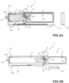
Figure 5A is a cross sectional view of a retriever system according to an embodiment of the invention, in a configuration wherein a first inflatable element of a buoyancy assembly inflates inside the hollow body of the retriever system, causing expulsion of a closure cap at an extremity of the hollow body; -
Figure 5B is a cross sectional view of a retriever system according to an embodiment of the invention, in a configuration wherein a buoyancy assembly is exiting the hollow body of the retriever system; -
Figure 6 is a cross sectional view of a retriever system according to an embodiment of the invention, in a configuration wherein a buoyancy assembly has exited the hollow body of the retriever system, while remaining attached to the hollow body.
-
- The following description of the embodiments refers to the accompanying drawings. The same reference numbers in different drawings identify the same or similar elements. The following detailed description does not limit the invention. Instead, the scope of the invention is defined by the appended claims.
- Reference throughout the specification to "one embodiment" or "an embodiment" means that a particular feature, structure or characteristic described in connection with an embodiment is included in at least one embodiment of the subject matter disclosed. Thus, the appearance of the phrases "in one embodiment" or "in an embodiment" in various places throughout the specification is not necessarily referring to the same embodiment. Further, the particular features, structures or characteristics may be combined in any suitable manner in one or more embodiments.
- According to various embodiments, it is proposed a
retriever system 1 coupled to a marine equipment. - The
retriever system 1 can be coupled to themarine equipment 9 by using for instance clamping means. Theretriever system 1 can be clamped directly on the streamer through collars, or clamped on positioning devices, or inserted inline along the streamer (dedicated inline module). - According to various embodiments, the
retriever system 1 may be integrated in the marine equipment. In particular, the body of the retriever system may be part of the corresponding body of the marine equipment. -
Figure 3 illustrates an embodiment, wherein the marine equipment is a control device, referred to as abird 9. The marine equipment provided with theretriever system 1, may also be a streamer or part of a streamer. Therefore, the following specification that is made with regard to abird 9 also applies to other marine equipment, such as a streamer, that may be provided with the retriever system. - In the embodiment illustrated at
Figure 3 , thebird 9 has twowings retriever system 1 extends between said at least twowings bird 9. The longitudinal axis of the retriever is parallel to the longitudinal axis of the bird. - As explained hereinafter, the
bird 9 may also include apressure detection system 95. - As illustrated in the embodiment of
Figure 4 , theretriever system 1 comprises ahollow body 100. Thehollow body 100 can be elongated. For instance, the hollow body has a general tubular or cylindrical shape. According to another embodiment, the shape may be not completely cylindrical but rather with a bulb shape. - The
hollow body 100 has afirst opening 111 at a first extremity. Acap 18 enables to close thefirst opening 111, as shown in particular inFigure 4 and Figure 5 , while atFigures 5A, 5B and6 thecap 18 has been removed. - According to a particular aspect, the
retriever system 1 comprises anattachment system 17, for instance a pin or a plastic screw, configured to enable attachment of thecap 18 to thehollow body 100 in a position wherein thecap 18 closes saidopening 111. Theattachment system 17 avoids non-desired ejection of the cap, in particular on board the vessel in a storage state of theretriever system 1. - The
attachment system 17 is configured for failing in predefined conditions, in particular when a predefined force or pressure is applied to thecap 18. - A
buoyancy assembly 2 is housed in thehollow body 100. Thebuoyancy assembly 2 is adapted to exit thehollow body 100 when thecap 18 is removed. - A
linkage system 19 enables to maintain thebuoyancy assembly 2 linked to thehollow body 100 of theretriever system 1, in particular when saidbuoyancy assembly 2 is out of saidhollow body 100. Thelinkage system 19 may comprise a flexible link, extensible or not, such as a rope, wire, string or cord. - According to embodiments, the
buoyancy assembly 2 comprises a firstinflatable element 3 and a secondinflatable element 4. - In the embodiments of
Figures 4 to 6 , the firstinflatable element 3 is a foldable element. In particular, the firstinflatable element 3 is folded when thebuoyancy assembly 2 is positioned in thehollow body 100 without being inflated (Figure 4 ), and can be unfolded by being inflated (Figures 5 to 6 ), what causes thebuoyancy assembly 2 to exit thehollow body 100 as explained hereinafter. In the embodiments ofFigures 4 to 6 , the secondinflatable element 4 is also a foldable element. - According to an embodiment and as illustrated in particular at
Figure 6 , the firstinflatable element 3 is configured to, when inflated and having exited thehollow body 100, present an elongated shape. - For instance, the first
inflatable element 3 has a cylindrical shape with a circular cross section. According to an embodiment and as illustrated atFigure 6 , the secondinflatable element 4 is configured to, when inflated and having exited thehollow body 100, present a spherical shape. - The
retriever system 1 comprises aninflating system 5 that includes an inflating generator and anactivation system inflatable element 3 with pressurized fluid and, at a later stage, provide the secondinflatable element 4 with pressurized fluid, as explained hereinafter. - The inflating generator can comprise a
pressurized gas bottle 53 or a mechanism to cause specific substance, such as powder or liquid or a solid compound, to react with another substance, and generate gas usable to inflate the firstinflatable element 3 and the secondinflatable element 4. - According to embodiments, at least part of the
inflating system 5 is inside the secondinflatable element 4. In particular and as illustrated inFigures 4 to 6 , the inflating generator, for instance a pressurized gas bottle, extends inside the secondinflatable element 4. - The first
inflatable element 3 and the secondinflatable element 4 are coupled one to the other by a coupling system. - According to embodiments, the coupling system comprises a first
annular element 23, a secondannular element 24 and between said first and second annular elements, anintermediate element 25. In particular, an opening of the firstinflatable element 3 is fixed to the firstannular element 23, and an opening of the secondinflatable element 4 is fixed to the secondannular element 24. - First
annular element 23, secondannular element 24 andintermediate element 25 may be connected one to the other or being parts of a same element. - According to embodiments, the coupling system, in particular the
intermediate element 25 as illustrated atFigures 4 to 6 , supports or receive theactivation system - A gas communication path is provided in the coupling system to allow the gas coming from the inflating generator to pass from the first
inflatable element 3 to the secondinflatable element 4. - As explained hereinafter, a
valve mechanism 54 enables to close or open the gas communication path. - In particular, the annular opening of the first
annular element 23 communicates with the interior of the firstinflatable element 3 and the annular opening of the secondannular element 24 communicates with the interior of the secondinflatable element 4. - According to the embodiments illustrated at
Figures 4 to 6 , theintermediate element 25 has agas path 235 that communicates with the annular opening of firstannular element 23, and thus with the interior of firstinflatable element 3, and agas path 245 that communicates with the annular opening of secondannular element 24, and thus with the interior of secondinflatable element 4. -
Activation system inflating system 5 may comprise apuncturing system 52 and apyroelectric actuator 51 to command thepuncturing system 52 so as to cause perforation of the inflating generator. Puncturingsystem 52 can comprise a punch or puncturing element that enables to open a gas pressurized bottle 53 (as an example of inflating generator) as a result of an activation of thepyroelectric actuator 51. - Activation of the inflating generator provides gas to the first
inflatable element 3 and, as explained hereafter, when a valve mechanism 54is moved in an open position, to the secondinflatable element 4. - The
hollow body 100 and thebuoyancy assembly 2 may be arranged so that, when the firstinflatable element 3 is in a rest position, and that theinflating system 5 is activated, the firstinflatable element 3 begins to be inflated by expanding inside the hollow body 100 (see for instanceFigure 5 ). - The inflating
system 5 comprises avalve mechanism 54 that is configured to prevent inflating of the secondinflatable element 4 while the secondinflatable element 4 has not exited the hollow body. In the embodiments ofFigures 4 to 6 , thevalve mechanism 54 is arranged so as to open the gas communication path after the secondinflatable element 4 has entirely exited thehollow body 100. - According to another embodiment, the
valve mechanism 54 that controls the opening or closure of the gas communication path between first and second inflatable elements, may be configured to prevent inflating of the second inflatable element while saidvalve mechanism 54, or said gas communication path, is submitted to a pressure that is under a predefined threshold, and to enable said inflating of the second inflatable element when said pressure reaches or exceeds said predefined threshold. In that case the pressure threshold may be settled in function of the technical features of the first inflatable element and of the second inflatable element. In particular the pressure threshold associated with the valve mechanism can be settled so as to let the second inflatable element exit the hollow body before inflation of said second inflatable element. According to embodiments, the pressure threshold associated with the second inflatable element may be settled so that the second inflatable element has exited the hollow body before that the internal pressure of said second inflatable element exceeds a predefined pressure value that may compromise or interfere with a safe exit of the second inflatable element from the hollow body. - In particular, while the second
inflatable element 4 is contained in the hollow body, thevalve mechanism 54 closes communication betweenpaths inflatable element 3 and the secondinflatable element 4 is closed. - According to embodiments, the
valve mechanism 54 is positioned in thebuoyancy assembly 2 between the firstinflatable element 3 and the secondinflatable element 4. - In particular, the
valve mechanism 54 is positioned upstream the secondinflatable element 4 by reference with the exit direction of thebuoyancy assembly 2 with regard to thehollow body 100. - According to particular embodiment, the
valve mechanism 54 is positioned proximate the extremity of the secondinflatable element 4 that is opposite to thecap 18. - According to embodiments, and as disclosed in
Figures 4 to 6 , thevalve mechanism 54 includes aspring 542 and aclosing element 541, also referred to as a spring-loaded finger. The closing element is movable between a closing position wherein theclosing element 541 closes the gas communication path between the firstinflatable element 3 and the secondinflatable element 4, and an opening position wherein theclosing element 541 frees the gas communication path between the firstinflatable element 3 and the secondinflatable element 4. - When the
buoyancy assembly 2 is housed in thehollow body 100, theclosing element 541 is maintained in the closing position by the internal wall of thehollow body 100, thus preventing theclosing element 541 to be moved (along a radial path of the buoyancy assembly) by thespring 542 in the opening position. Thespring 542 is thus maintained in a loaded state by thehollow body 10 as theclosing element 541 is maintained in the closing position by thehollow body 10. - When the portion of the
buoyancy assembly 2 that has thevalve mechanism 54, has exited thehollow body 100, the internal wall of the hollow is no more in contact with theclosing element 541 so that theclosing element 541 is moved in the open position by thespring 542 that unloads. The gas communication path is thus free. - The
valve mechanism 54 thus enables to control the gas communication between firstinflatable element 3 and secondinflatable element 4. - When activated, inflating
system 5 causes inflation of the firstinflatable element 3. Inflation of the firstinflatable element 3 causes thebuoyancy assembly 2 to push onto the cap 18 (Figure 5 ), what leads to the ejection of the cap (Figure 5A ) when the force or pressure exerted by thebuoyancy assembly 2 on thecap 18 is superior to a force or pressure threshold. - According to embodiment said force or pressure threshold corresponds to a force or pressure necessary to brake the
attachment system 17 arranged between thecap 18 and thehollow body 100. Theattachment system 17 can comprise a screw, such as a plastic screw cooperating with a thread arranged in the cap. - As illustrated in the embodiment of
Figures 4 to 6 , thepressurized gas bottle 53 is fixed to the coupling system so that the pressure inside the inflatablefirst element 3 generates a force that is transmitted to thepressurized gas bottle 53 that, as a result, pushes onto thecap 18. - Once the
cap 18 has been ejected, thebuoyancy assembly 2 exits out of the hollow body 100 (Figure 6 ). - According to embodiments, the inflating
system 5 is configured to start inflating the secondinflatable element 4 when said secondinflatable element 4 is out of thehollow body 100. - According to another embodiment, the second
inflatable element 4 may start inflating a little in thehollow body 100 while thecap 18 has not yet been ejected. Once thecap 18 is ejected and that the secondinflatable element 4 has exited thehollow body 100, inflation of said second inflatable element can continue outside thehollow body 100. - Such conception of the
retriever system 1 enables to cause the secondinflatable element 4 to exit thehollow body 100 when the firstinflatable element 3 is being inflated or is inflated and that thecap 18 is removed/expulsed, while the secondinflatable element 4 has not yet started to inflate or has inflated just a little, thus preventing the secondinflatable element 4 from being damaged, for instance by being cut by the edge of theopening 111, when exiting the hollow body. - Activation of the
inflation system 5 causes the firstinflatable element 3 to inflate (Figure 5 ), what causes thecap 18 to be ejected as a result of the force applied by thebuoyancy assembly 2 on the interior face of the cap 18 (Figure 5A ). Then, thebuoyancy assembly 2 begins to exit thehollow body 100, having the secondinflatable element 4, that was arranged proximate to the now expulsedcap 18, exiting first the hollow body. Thanks to the positioning of thevalve mechanism 54 between the first and secondinflatable elements valve mechanism 54 has exited the hollow body, the second inflatable elements has already exited the hollow body, and thevalve mechanism 54 automatically switches on the opened position that frees the communication between the firstinflatable element 3 and the second inflatable element 4 (Figure 5B ). The pressurized gas contained in thepressurized gas bottle 53 thus flows from the firstinflatable element 3 to the secondinflatable element 4 causing the secondinflatable element 4 to inflate (Figure 6 ). - As illustrated at
Figure 6 , when inflated, the secondinflatable element 4 may have a volume greater than the one of the firstinflatable element 3. - The retriever system comprises a
valve system 61 that enables, when opened, to equalize pressure inside and outside the hollow body. Thevalve system 61 can be moved between a closed position wherein thevalve system 61 closes asecond opening 106 of thehollow body 100, and an opened position wherein saidsecond opening 106 of thehollow body 100 is opened so as to let external water enter thehollow body 100. - As illustrated in the embodiments of
Figures 4 to 6 , thesecond opening 106 is opposite to thefirst opening 111. - In the opened position of the
valve system 61, water fills the hollow-body around thebuoyancy assembly 2. As a result, pressure inside and outside the hollow body is equalized, what makes easier the ejection ofcap 18. - The first
inflatable element 3 is configured to, when being inflated, move thevalve 61 system from the closed position to the opened position. - The
retriever system 1 comprises acoupling interface 63 that is coupled to thevalve 61 system and that partially covers the firstinflatable element 3 to enable guiding of the movement of thevalve 61 system from the closed position to the opened position when the firstinflatable element 3 is inflating. In particular, the firstinflatable element 3 unfolds by being inflated what causes the firstinflatable element 3 to push onto thecoupling interface 63 that supports thevalve 61 system. - However, the
coupling interface 63 is designed to let the firstinflatable element 3 exits out of thehollow body 100 through thefirst opening 111 once thecap 18 is removed. In other words, the coupling interface does not restrain movement of the buoyancy assembly in the direction of the cap. - According to embodiments, the
retriever system 1 is configured to activate theinflating system 5 at a predefined depth to cause inflation of the firstinflatable element 3, what moves thevalve 61 system in the opened position. The predefined depth may correspond to high depth. The predefined depth may for instance be between 80 and 90 meters, in particular when considering seismic applications. - The area of the outer surface of the
cap 18, that corresponds to the surface of the cap that is in contact with water when in a closing position of the cap and when theretriever system 1 is underwater, before opening of thevalve 61 system, can be defined in function of (i) the area of the outer surface of thevalve 61 system, that corresponds to the surface of thevalve 61 system that is in contact with water when in the closed position of the valve system and when the retriever is underwater, and (ii) the water depth, or corresponding pressure, at which theinflating system 5 is intended to be activated. - The value of the ratio of the area of the outer surface of the
cap 18 and the area of the outer surface of thevalve 61 system may for instance be about 100. - Contrary to some state-of-the-art retriever systems that cannot work at high depth because required pressure to release airbag equals external water pressure, the
valve system 61 of the retriever system according to embodiments enables the retriever system to be activated at high depth. - According to a particular embodiment and as illustrated at
Figure 3 , thebird 9 comprises apressure detection system 95. Thepressure detection system 95 is configured to detect or measure the water pressure on the marine equipment. - The inflating
system 5 may be configured to be activated in function of a pressure detected by a pressure detection system such as saidpressure detection system 95. In particular, thebird 9 may be configured to send an activation signal (also called trigger command) to the activatingsystem inflating system 5 Thepressure detection system 95 of the bird may communicate with the activatingsystem inflating system 5 with radio means or with connectors such as wire(s). - The
activation system - a receiver of the bird or a receiver of the retriever system receives a remote command to actuate the
inflating system 5. The remote command may be emitted from remote device, for instance on board a vessel, - a physical parameter, such as pressure outside the bird, exceeds a threshold and a corresponding detection system, that can be integrated or deported from the retriever system, triggers the
activation system - The
retriever system 1 can include a pressure detection system that is configured to activate theactivation system inflating system 5 in function of the pressure detected or measured by said pressure detection system. - In another embodiment, the
activation system inflating system 5 may be associated with a radio receiver included in theretriever system 1 and adapted to receive an activation signal from a remote transmitter, for instance positioned on board a vessel, and to control theactivation system Activation system inflating system 5 may also be configured to be manually controlled by an operator. - An embodiment of a method for retrieving a marine equipment that can be executed with a
retriever system 1 according to various embodiments recited above, is now discussed. The method includes a step of activating theactivation system pyroelectric actuator 51 causes thepuncturing system 52 to perforate the inflating generator (seeFigure 5 ). Then the gas exiting the inflating generator fills and unfolds the firstinflatable element 3. - In case the retriever system is provided with the
valve system 61 andcorresponding coupling interface 63, inflating of the firstinflatable element 3 causes thevalve 61 system to be moved in the open position by being pushed by the firstinflatable element 3. Then water enters the hollowbody trough opening 106 and fills the hollow body around thebuoyancy assembly 2. Thus, pressure tends to equalize between inside and outside the hollow body 100 (or container) and reduce the effort needed to open (or eject) thecap 18. - Inflating of the first
inflatable element 3 make the firstinflatable element 3 extend and thus firstinflatable element 3 pushes the buoyancy assembly, and in particular the inflating generator, against thecap 18. Thecap 18 is then ejected from the hollow body. When thecap 18 is ejected,first opening 111 is free and thebuoyancy assembly 2 can exit thehollow body 100. - According to a preferred embodiment, expulsion or removing of the cap results from the inflating of the first
inflatable element 3. But according to other embodiments, the cap may be expulsed by other means independently of the inflating, for instance by a pressure mechanism coupled to that cap and that is automatically activated on a pressure threshold to cause the ejection of the cap. - Once the portion of the buoyancy assembly that has the
valve mechanism 54, has exited the hollow body, thevalve mechanism 54 moves in an open position that enables to inflate the secondinflatable element 4 that has exited thehollow body 100. In particular the finger that was blocking the gas communication path between firstinflatable element 3 and secondinflatable element 4, is moved by its associated spring away from the communication path so that gas can pass from the firstinflatable element 3 to secondinflatable element 4. - In other words, the first and second inflatable elements are inflated in a two-time sequence.
- According to embodiments, the
retriever system 1 can be configured so that, when theinflating system 5 is activated, the firstinflatable element 3 is inflated at least partially before inflation of the secondinflatable element 4, so as to let the secondinflatable element 4 exit thehollow body 100 before inflation of said secondinflatable element 4 or before that the internal pressure of said secondinflatable element 4 exceeds a predefined threshold. - According to a particular embodiment that is not claimed, the retriever system comprises a hollow body and a cap as explained above. The buoyancy assembly may comprise an inflatable element, for instance only one inflatable element or a plurality, and an inflating system configured to, when activated, inflate said inflatable element. Inflating system may be as recited above. In this particular embodiment the retriever system comprises a valve system that can be moved between a closed position wherein the valve system closes a second opening of the hollow body, and an opened position wherein said second opening of the hollow body is opened so as to let external water enter the hollow body.
- The inflatable element is configured to, when being inflated, move the valve system from the closed position to the opened position. The inflatable element can be a foldable bag as proposed in the other embodiments. The inflatable element may be designed so that entering of the water in the hollow body enables the inflatable element to eject the cap so as to let the inflatable element exit the hollow body while remaining linked to the hollow body.
- The retriever system proposed in the above embodiment may be used to execute a method for retrieving a marine equipment coupled to a retriever system. The method comprises a step of inflating the inflatable element to move the valve system from the closed position to the opened position that lets external water enter the hollow body. Then the cap is ejected by the force exerted by the inflatable element directly or indirectly on the cap. The inflatable element exits the hollow body while remaining linked to the hollow body.
- According to embodiments, the retriever system provides a compact retriever that limit acoustic and mechanical noise on seismic acquisition. Reduced dimension of the retriever system enables the retriever system to be positioned on the body of the bird, in particular between two wings of the bird. Noise on seismic sensors is minimized. Compacity of the retriever system allows its storing and easy handling on deck. Similarly, using low weight material, such as composite material, for designing the hollow body of the system retriever enable to ease its handling on deck.
- The disclosed embodiments provide a retriever system and a method for retrieving a marine equipment. It should be understood that this description is not intended to limit the invention. On the contrary, the exemplary embodiments are intended to cover alternatives, modifications and equivalents, which are included in the scope of the invention as defined by the appended claims. Further, in the detailed description of the exemplary embodiments, numerous specific details are set forth in order to provide a comprehensive understanding of the claimed invention. However, one skilled in the art would understand that various embodiments may be practiced without such specific details.
- This written description uses examples of the subject matter disclosed to enable any person skilled in the art to practice the same, including making and using any devices or systems and performing any incorporated methods. The patentable scope of the subject matter is defined by the claims, and may include other examples that occur to those skilled in the art. Such other examples are intended to be within the scope of the claims.
Claims (12)
- A retriever system (1) for retrieving a marine equipment (9), said retriever system (1) comprising:- a hollow body (100) having a first opening (111),- a cap (18) adapted to close the first opening (111) of the hollow body (100) and adapted to be removed to free said first opening (111),- a buoyancy assembly (2) housed in the hollow body (100) and adapted to exit the hollow body when the cap (18) is removed,- a linkage system (19) to maintain the buoyancy assembly (2) linked to the hollow body of the retriever system, when said buoyancy assembly (2) is out of said hollow body (100) of the retriever system,wherein said buoyancy assembly (2) comprises:- a first inflatable element (3) and a second inflatable element (4),- an inflating system (5) configured to, when activated, inflate the first inflatable element (3), so as to enable exiting of at least the second inflatable element (4) of the buoyancy assembly (2) out of the hollow body (100),said inflating system (5) being configured to start or to continue inflating the second inflatable element (4) when said second inflatable element (4) is out of the hollow body (100),and wherein the inflating system (5) comprises an inflating generator and an activation system (51, 52) to activate the inflating generator to provide the first inflatable element (3) with gas;characterised in thatthe inflating system (5) further comprises:
a valve mechanism (54) that is configured to:- prevent inflating of the second inflatable element (4) while said second inflatable element (4) extends inside the hollow body, and- enable said inflating of the second inflatable element (4) after the second inflatable element (4) has exited the hollow body. - The retriever system (1) according to claim 1, wherein the retriever system (1) is configured so that, when the inflating system (5) is activated, the first inflatable element (3) is inflated at least partially before inflation of the second inflatable element (4).
- The retriever system (1) according to claim 1 or 2, wherein the retriever system comprises a valve system (61) that can be moved between:- a closed position wherein the valve system (61) closes a second opening of the hollow body (100), and- an opened position wherein said second opening of the hollow body (100) is opened so as to let external water enter the hollow body (100).
- The retriever system (1) according to claim 3, wherein the first inflatable element (3) is configured to, when being inflated, move the valve system (61) from the closed position to the opened position,
wherein the retriever system (1) comprises a coupling interface (63) that is coupled to the valve system (61) and that partially covers the first inflatable element (3) when the cap (18) closes the first opening (111) of the hollow body, to enable guiding of the movement of the valve system (61) from the closed position to the opened position when the first inflatable element (3) is inflating, while letting the first inflatable element (3) exit out the hollow body (100) through the first opening (111) once the cap (18) is removed. - The retriever system (1) according to any one of claims 3 to 4, wherein an area of an outer surface of the cap (18), that corresponds to a surface of the cap that is in contact with water when in a closing position of the cap and when the retriever system (1) is underwater, is defined in function of:- an area of an outer surface of the valve system (61), that corresponds to a surface of the valve system (61) that is in contact with water when in the closed position of the valve system and when the retriever system is underwater, and- water depth, or corresponding pressure, at which the inflating system (5) is intended to be activated.
- The retriever system (1) according to any one of claims 1 to 5, wherein the valve mechanism (54) includes a spring (542) and a closing element (541) that is movable between a closing position wherein the closing element (541) closes a gas communication path between the first inflatable element (3) and the second inflatable element (4), and an opening position wherein the closing element (541) frees the gas communication path between the first inflatable element and the second inflatable element (4),wherein, when the buoyancy assembly (2) is housed in the hollow body (100), the closing element (541) is maintained in the closing position by the hollow body (100) that prevents the closing element (541) to be moved by the spring (542) in the opening position, and,when the portion of the buoyancy assembly (2) that has the valve mechanism (54), has exited the hollow body (100), the closing element (541) is moved in the open position by said spring (542) to free the gas communication path.
- The retriever system (1) according to any one of claims 1 to 6, wherein at least part of the inflating system (5) is inside the second inflatable element (4).
- The retriever system (1) according to any one of claims 1 to 7, wherein the retriever system (1) comprises an attachment system (17), for instance a pin or a plastic screw, configured to enable attachment of the cap (18) to the hollow body (100) in a position wherein the cap (18) closes said opening (111), said attachment system being configured for failing in predefined conditions, for instance when a predefined force or pressure is applied to the cap (18).
- An assembly comprising:- a marine equipment (9), and- a retriever system (1) according to any one of claims 1 to 8, said retriever system (1) being coupled to said marine equipment (9).
- The assembly of claim 9, wherein the marine equipment (9) is a control device, referred to as a bird, having at least two wings (91, 92) for controlling a position of an instrumented cable, referred to as a streamer, adapted to be towed in water, and the retriever system (1) extends between said at least two wings (91, 92) of the control device (9).
- The assembly of claim 10, wherein the marine equipment (9) comprises a pressure detection system (95), and the inflating system (5) is configured to be activated in function of a pressure detected by said pressure detection system.
- A method for retrieving a marine equipment (9) coupled to a retriever system (1) according to any one of claims 1 to 8, wherein the method comprises the following steps:- inflating the first inflatable element (3) causing exit, from the hollow body (100), of at least the second inflatable element (4) of the buoyancy assembly (2), and- inflating the second inflatable element (4) that has exited the hollow body (100).
Applications Claiming Priority (2)
| Application Number | Priority Date | Filing Date | Title |
|---|---|---|---|
| US16/205,796 US10562598B1 (en) | 2018-11-30 | 2018-11-30 | Retriever system for a marine equipment and method |
| PCT/IB2019/001324 WO2020109868A2 (en) | 2018-11-30 | 2019-11-29 | Retriever system for a marine equipment and method |
Publications (2)
| Publication Number | Publication Date |
|---|---|
| EP3887243A2 EP3887243A2 (en) | 2021-10-06 |
| EP3887243B1 true EP3887243B1 (en) | 2025-06-18 |
Family
ID=69185622
Family Applications (1)
| Application Number | Title | Priority Date | Filing Date |
|---|---|---|---|
| EP19839658.2A Active EP3887243B1 (en) | 2018-11-30 | 2019-11-29 | Retriever system for a marine equipment and method |
Country Status (6)
| Country | Link |
|---|---|
| US (1) | US10562598B1 (en) |
| EP (1) | EP3887243B1 (en) |
| AU (1) | AU2019386380B2 (en) |
| BR (1) | BR112021009995A2 (en) |
| MX (1) | MX2021005873A (en) |
| WO (1) | WO2020109868A2 (en) |
Families Citing this family (1)
| Publication number | Priority date | Publication date | Assignee | Title |
|---|---|---|---|---|
| US11104405B1 (en) * | 2020-12-02 | 2021-08-31 | The United States Of America As Represented By The Secretary Of The Navy | Deep water buoyancy device |
Family Cites Families (8)
| Publication number | Priority date | Publication date | Assignee | Title |
|---|---|---|---|---|
| US3123842A (en) * | 1964-03-10 | Gas ejected apparatus for locating | ||
| GB1169273A (en) * | 1967-03-09 | 1969-11-05 | Ml Aviation Co Ltd | Inflatable Buoys |
| US4823325A (en) * | 1984-03-12 | 1989-04-18 | Syntrieve, Inc. | Streamer retrieval system and method |
| US5404339A (en) * | 1994-02-25 | 1995-04-04 | Concord Technologies Inc. | Retriever for a seismic streamer cable |
| US7232354B2 (en) * | 2005-06-09 | 2007-06-19 | Manfred Bradley Olson | Inflatable buoyancy device with water-dependant triggering mechanism |
| US7540796B2 (en) * | 2007-06-15 | 2009-06-02 | Fredrick Spears | Inflatable buoyancy device with water-dependant triggering mechanism |
| US8998535B2 (en) * | 2012-05-18 | 2015-04-07 | Pgs Geophysical As | Method and system of retriever systems for marine geophysical survey sensor streamers |
| EP2857868B1 (en) | 2013-10-07 | 2018-12-05 | Sercel | Wing releasing system for a navigation control device |
-
2018
- 2018-11-30 US US16/205,796 patent/US10562598B1/en active Active
-
2019
- 2019-11-29 BR BR112021009995-6A patent/BR112021009995A2/en active Search and Examination
- 2019-11-29 MX MX2021005873A patent/MX2021005873A/en unknown
- 2019-11-29 AU AU2019386380A patent/AU2019386380B2/en active Active
- 2019-11-29 EP EP19839658.2A patent/EP3887243B1/en active Active
- 2019-11-29 WO PCT/IB2019/001324 patent/WO2020109868A2/en not_active Ceased
Also Published As
| Publication number | Publication date |
|---|---|
| WO2020109868A3 (en) | 2020-07-23 |
| MX2021005873A (en) | 2021-10-13 |
| AU2019386380B2 (en) | 2023-02-09 |
| AU2019386380A1 (en) | 2021-06-24 |
| BR112021009995A2 (en) | 2021-08-17 |
| US10562598B1 (en) | 2020-02-18 |
| WO2020109868A2 (en) | 2020-06-04 |
| EP3887243A2 (en) | 2021-10-06 |
Similar Documents
| Publication | Publication Date | Title |
|---|---|---|
| US7310287B2 (en) | Method and apparatus for seismic data acquisition | |
| EP3177944B1 (en) | Overboard system for deployment and retrieval of autonomous seismic nodes | |
| CA2581193C (en) | Method and apparatus for seismic data acquisition | |
| US6612886B2 (en) | In-line cable retriever | |
| US4823325A (en) | Streamer retrieval system and method | |
| EP2770345A2 (en) | Activation Electronics and Method for Seismic Equipment Recovery Device | |
| US9290239B2 (en) | Control device for positioning an instrumented cable provided with buoyancy means for retrieving the control device and instrumented cable from submerged positioning | |
| US20180052246A1 (en) | Wavegate for a seismic surface vessel | |
| AU2019386380B2 (en) | Retriever system for a marine equipment and method | |
| US8926222B2 (en) | Method and system of depth triggers for marine geophysical survey cable retriever systems | |
| EP3304132B1 (en) | Smart streamer recovery device | |
| CA2887400C (en) | Method and apparatus for seismic data acquisition | |
| EP2910978A1 (en) | Retriever system for a streamer |
Legal Events
| Date | Code | Title | Description |
|---|---|---|---|
| STAA | Information on the status of an ep patent application or granted ep patent |
Free format text: STATUS: UNKNOWN |
|
| STAA | Information on the status of an ep patent application or granted ep patent |
Free format text: STATUS: THE INTERNATIONAL PUBLICATION HAS BEEN MADE |
|
| PUAI | Public reference made under article 153(3) epc to a published international application that has entered the european phase |
Free format text: ORIGINAL CODE: 0009012 |
|
| STAA | Information on the status of an ep patent application or granted ep patent |
Free format text: STATUS: REQUEST FOR EXAMINATION WAS MADE |
|
| 17P | Request for examination filed |
Effective date: 20210503 |
|
| AK | Designated contracting states |
Kind code of ref document: A2 Designated state(s): AL AT BE BG CH CY CZ DE DK EE ES FI FR GB GR HR HU IE IS IT LI LT LU LV MC MK MT NL NO PL PT RO RS SE SI SK SM TR |
|
| DAV | Request for validation of the european patent (deleted) | ||
| DAX | Request for extension of the european patent (deleted) | ||
| STAA | Information on the status of an ep patent application or granted ep patent |
Free format text: STATUS: EXAMINATION IS IN PROGRESS |
|
| 17Q | First examination report despatched |
Effective date: 20230322 |
|
| REG | Reference to a national code |
Ref country code: DE Ref legal event code: R079 Ipc: G01V0001380000 Ref country code: DE Ref legal event code: R079 Ref document number: 602019071348 Country of ref document: DE Free format text: PREVIOUS MAIN CLASS: B63B0022120000 Ipc: G01V0001380000 |
|
| GRAP | Despatch of communication of intention to grant a patent |
Free format text: ORIGINAL CODE: EPIDOSNIGR1 |
|
| STAA | Information on the status of an ep patent application or granted ep patent |
Free format text: STATUS: GRANT OF PATENT IS INTENDED |
|
| RIC1 | Information provided on ipc code assigned before grant |
Ipc: G01V 1/20 20060101ALN20250107BHEP Ipc: B63B 21/66 20060101ALI20250107BHEP Ipc: B63B 22/12 20060101ALI20250107BHEP Ipc: G01V 1/38 20060101AFI20250107BHEP |
|
| INTG | Intention to grant announced |
Effective date: 20250122 |
|
| GRAS | Grant fee paid |
Free format text: ORIGINAL CODE: EPIDOSNIGR3 |
|
| GRAA | (expected) grant |
Free format text: ORIGINAL CODE: 0009210 |
|
| STAA | Information on the status of an ep patent application or granted ep patent |
Free format text: STATUS: THE PATENT HAS BEEN GRANTED |
|
| AK | Designated contracting states |
Kind code of ref document: B1 Designated state(s): AL AT BE BG CH CY CZ DE DK EE ES FI FR GB GR HR HU IE IS IT LI LT LU LV MC MK MT NL NO PL PT RO RS SE SI SK SM TR |
|
| REG | Reference to a national code |
Ref country code: GB Ref legal event code: FG4D |
|
| REG | Reference to a national code |
Ref country code: CH Ref legal event code: EP |
|
| REG | Reference to a national code |
Ref country code: DE Ref legal event code: R096 Ref document number: 602019071348 Country of ref document: DE |
|
| REG | Reference to a national code |
Ref country code: CH Ref legal event code: EP |
|
| REG | Reference to a national code |
Ref country code: IE Ref legal event code: FG4D |
|
| PG25 | Lapsed in a contracting state [announced via postgrant information from national office to epo] |
Ref country code: FI Free format text: LAPSE BECAUSE OF FAILURE TO SUBMIT A TRANSLATION OF THE DESCRIPTION OR TO PAY THE FEE WITHIN THE PRESCRIBED TIME-LIMIT Effective date: 20250618 |
|
| REG | Reference to a national code |
Ref country code: LT Ref legal event code: MG9D |
|
| PG25 | Lapsed in a contracting state [announced via postgrant information from national office to epo] |
Ref country code: GR Free format text: LAPSE BECAUSE OF FAILURE TO SUBMIT A TRANSLATION OF THE DESCRIPTION OR TO PAY THE FEE WITHIN THE PRESCRIBED TIME-LIMIT Effective date: 20250919 |
|
| PG25 | Lapsed in a contracting state [announced via postgrant information from national office to epo] |
Ref country code: BG Free format text: LAPSE BECAUSE OF FAILURE TO SUBMIT A TRANSLATION OF THE DESCRIPTION OR TO PAY THE FEE WITHIN THE PRESCRIBED TIME-LIMIT Effective date: 20250618 |
|
| PG25 | Lapsed in a contracting state [announced via postgrant information from national office to epo] |
Ref country code: HR Free format text: LAPSE BECAUSE OF FAILURE TO SUBMIT A TRANSLATION OF THE DESCRIPTION OR TO PAY THE FEE WITHIN THE PRESCRIBED TIME-LIMIT Effective date: 20250618 |
|
| PG25 | Lapsed in a contracting state [announced via postgrant information from national office to epo] |
Ref country code: RS Free format text: LAPSE BECAUSE OF FAILURE TO SUBMIT A TRANSLATION OF THE DESCRIPTION OR TO PAY THE FEE WITHIN THE PRESCRIBED TIME-LIMIT Effective date: 20250918 |
|
| REG | Reference to a national code |
Ref country code: NL Ref legal event code: MP Effective date: 20250618 |
|
| PG25 | Lapsed in a contracting state [announced via postgrant information from national office to epo] |
Ref country code: LV Free format text: LAPSE BECAUSE OF FAILURE TO SUBMIT A TRANSLATION OF THE DESCRIPTION OR TO PAY THE FEE WITHIN THE PRESCRIBED TIME-LIMIT Effective date: 20250618 |
|
| PG25 | Lapsed in a contracting state [announced via postgrant information from national office to epo] |
Ref country code: NL Free format text: LAPSE BECAUSE OF FAILURE TO SUBMIT A TRANSLATION OF THE DESCRIPTION OR TO PAY THE FEE WITHIN THE PRESCRIBED TIME-LIMIT Effective date: 20250618 |
|
| PG25 | Lapsed in a contracting state [announced via postgrant information from national office to epo] |
Ref country code: PT Free format text: LAPSE BECAUSE OF FAILURE TO SUBMIT A TRANSLATION OF THE DESCRIPTION OR TO PAY THE FEE WITHIN THE PRESCRIBED TIME-LIMIT Effective date: 20251020 |
|
| REG | Reference to a national code |
Ref country code: AT Ref legal event code: MK05 Ref document number: 1804681 Country of ref document: AT Kind code of ref document: T Effective date: 20250618 |
|
| PG25 | Lapsed in a contracting state [announced via postgrant information from national office to epo] |
Ref country code: IS Free format text: LAPSE BECAUSE OF FAILURE TO SUBMIT A TRANSLATION OF THE DESCRIPTION OR TO PAY THE FEE WITHIN THE PRESCRIBED TIME-LIMIT Effective date: 20251018 |
|
| PGFP | Annual fee paid to national office [announced via postgrant information from national office to epo] |
Ref country code: GB Payment date: 20251121 Year of fee payment: 7 |
|
| PGFP | Annual fee paid to national office [announced via postgrant information from national office to epo] |
Ref country code: NO Payment date: 20251125 Year of fee payment: 7 |
|
| PG25 | Lapsed in a contracting state [announced via postgrant information from national office to epo] |
Ref country code: AT Free format text: LAPSE BECAUSE OF FAILURE TO SUBMIT A TRANSLATION OF THE DESCRIPTION OR TO PAY THE FEE WITHIN THE PRESCRIBED TIME-LIMIT Effective date: 20250618 Ref country code: SM Free format text: LAPSE BECAUSE OF FAILURE TO SUBMIT A TRANSLATION OF THE DESCRIPTION OR TO PAY THE FEE WITHIN THE PRESCRIBED TIME-LIMIT Effective date: 20250618 |
|
| PG25 | Lapsed in a contracting state [announced via postgrant information from national office to epo] |
Ref country code: CZ Free format text: LAPSE BECAUSE OF FAILURE TO SUBMIT A TRANSLATION OF THE DESCRIPTION OR TO PAY THE FEE WITHIN THE PRESCRIBED TIME-LIMIT Effective date: 20250618 |
|
| PG25 | Lapsed in a contracting state [announced via postgrant information from national office to epo] |
Ref country code: PL Free format text: LAPSE BECAUSE OF FAILURE TO SUBMIT A TRANSLATION OF THE DESCRIPTION OR TO PAY THE FEE WITHIN THE PRESCRIBED TIME-LIMIT Effective date: 20250618 |
|
| PG25 | Lapsed in a contracting state [announced via postgrant information from national office to epo] |
Ref country code: EE Free format text: LAPSE BECAUSE OF FAILURE TO SUBMIT A TRANSLATION OF THE DESCRIPTION OR TO PAY THE FEE WITHIN THE PRESCRIBED TIME-LIMIT Effective date: 20250618 |
|
| PG25 | Lapsed in a contracting state [announced via postgrant information from national office to epo] |
Ref country code: RO Free format text: LAPSE BECAUSE OF FAILURE TO SUBMIT A TRANSLATION OF THE DESCRIPTION OR TO PAY THE FEE WITHIN THE PRESCRIBED TIME-LIMIT Effective date: 20250618 Ref country code: SK Free format text: LAPSE BECAUSE OF FAILURE TO SUBMIT A TRANSLATION OF THE DESCRIPTION OR TO PAY THE FEE WITHIN THE PRESCRIBED TIME-LIMIT Effective date: 20250618 |
|
| PG25 | Lapsed in a contracting state [announced via postgrant information from national office to epo] |
Ref country code: ES Free format text: LAPSE BECAUSE OF FAILURE TO SUBMIT A TRANSLATION OF THE DESCRIPTION OR TO PAY THE FEE WITHIN THE PRESCRIBED TIME-LIMIT Effective date: 20250618 |
|
| REG | Reference to a national code |
Ref country code: DE Ref legal event code: R097 Ref document number: 602019071348 Country of ref document: DE |
|
| PG25 | Lapsed in a contracting state [announced via postgrant information from national office to epo] |
Ref country code: DK Free format text: LAPSE BECAUSE OF FAILURE TO SUBMIT A TRANSLATION OF THE DESCRIPTION OR TO PAY THE FEE WITHIN THE PRESCRIBED TIME-LIMIT Effective date: 20250618 |
|
| PG25 | Lapsed in a contracting state [announced via postgrant information from national office to epo] |
Ref country code: IT Free format text: LAPSE BECAUSE OF FAILURE TO SUBMIT A TRANSLATION OF THE DESCRIPTION OR TO PAY THE FEE WITHIN THE PRESCRIBED TIME-LIMIT Effective date: 20250618 |
|
| PLBE | No opposition filed within time limit |
Free format text: ORIGINAL CODE: 0009261 |
|
| STAA | Information on the status of an ep patent application or granted ep patent |
Free format text: STATUS: NO OPPOSITION FILED WITHIN TIME LIMIT |
|
| REG | Reference to a national code |
Ref country code: CH Ref legal event code: L10 Free format text: ST27 STATUS EVENT CODE: U-0-0-L10-L00 (AS PROVIDED BY THE NATIONAL OFFICE) Effective date: 20260430 |