EP3886742B1 - Surgical tool for positioning a surgical device, surgical device and kit - Google Patents
Surgical tool for positioning a surgical device, surgical device and kit Download PDFInfo
- Publication number
- EP3886742B1 EP3886742B1 EP19805508.9A EP19805508A EP3886742B1 EP 3886742 B1 EP3886742 B1 EP 3886742B1 EP 19805508 A EP19805508 A EP 19805508A EP 3886742 B1 EP3886742 B1 EP 3886742B1
- Authority
- EP
- European Patent Office
- Prior art keywords
- surgical
- surgical device
- tool
- free end
- coupling system
- Prior art date
- Legal status (The legal status is an assumption and is not a legal conclusion. Google has not performed a legal analysis and makes no representation as to the accuracy of the status listed.)
- Active
Links
Images




Classifications
-
- A—HUMAN NECESSITIES
- A61—MEDICAL OR VETERINARY SCIENCE; HYGIENE
- A61B—DIAGNOSIS; SURGERY; IDENTIFICATION
- A61B17/00—Surgical instruments, devices or methods
- A61B17/56—Surgical instruments or methods for treatment of bones or joints; Devices specially adapted therefor
- A61B17/58—Surgical instruments or methods for treatment of bones or joints; Devices specially adapted therefor for osteosynthesis, e.g. bone plates, screws or setting implements
- A61B17/88—Osteosynthesis instruments; Methods or means for implanting or extracting internal or external fixation devices
- A61B17/8875—Screwdrivers, spanners or wrenches
- A61B17/8886—Screwdrivers, spanners or wrenches holding the screw head
-
- A—HUMAN NECESSITIES
- A61—MEDICAL OR VETERINARY SCIENCE; HYGIENE
- A61B—DIAGNOSIS; SURGERY; IDENTIFICATION
- A61B17/00—Surgical instruments, devices or methods
- A61B17/56—Surgical instruments or methods for treatment of bones or joints; Devices specially adapted therefor
- A61B17/58—Surgical instruments or methods for treatment of bones or joints; Devices specially adapted therefor for osteosynthesis, e.g. bone plates, screws or setting implements
- A61B17/88—Osteosynthesis instruments; Methods or means for implanting or extracting internal or external fixation devices
- A61B17/8875—Screwdrivers, spanners or wrenches
- A61B17/8886—Screwdrivers, spanners or wrenches holding the screw head
- A61B17/8888—Screwdrivers, spanners or wrenches holding the screw head at its central region
-
- A—HUMAN NECESSITIES
- A61—MEDICAL OR VETERINARY SCIENCE; HYGIENE
- A61B—DIAGNOSIS; SURGERY; IDENTIFICATION
- A61B17/00—Surgical instruments, devices or methods
- A61B17/16—Instruments for performing osteoclasis; Drills or chisels for bones; Trepans
- A61B17/1655—Instruments for performing osteoclasis; Drills or chisels for bones; Trepans for tapping
-
- A—HUMAN NECESSITIES
- A61—MEDICAL OR VETERINARY SCIENCE; HYGIENE
- A61B—DIAGNOSIS; SURGERY; IDENTIFICATION
- A61B17/00—Surgical instruments, devices or methods
- A61B17/56—Surgical instruments or methods for treatment of bones or joints; Devices specially adapted therefor
- A61B17/58—Surgical instruments or methods for treatment of bones or joints; Devices specially adapted therefor for osteosynthesis, e.g. bone plates, screws or setting implements
- A61B17/68—Internal fixation devices, including fasteners and spinal fixators, even if a part thereof projects from the skin
- A61B17/70—Spinal positioners or stabilisers, e.g. stabilisers comprising fluid filler in an implant
- A61B17/7074—Tools specially adapted for spinal fixation operations other than for bone removal or filler handling
- A61B17/7076—Tools specially adapted for spinal fixation operations other than for bone removal or filler handling for driving, positioning or assembling spinal clamps or bone anchors specially adapted for spinal fixation
- A61B17/7077—Tools specially adapted for spinal fixation operations other than for bone removal or filler handling for driving, positioning or assembling spinal clamps or bone anchors specially adapted for spinal fixation for moving bone anchors attached to vertebrae, thereby displacing the vertebrae
-
- A—HUMAN NECESSITIES
- A61—MEDICAL OR VETERINARY SCIENCE; HYGIENE
- A61B—DIAGNOSIS; SURGERY; IDENTIFICATION
- A61B17/00—Surgical instruments, devices or methods
- A61B17/56—Surgical instruments or methods for treatment of bones or joints; Devices specially adapted therefor
- A61B17/58—Surgical instruments or methods for treatment of bones or joints; Devices specially adapted therefor for osteosynthesis, e.g. bone plates, screws or setting implements
- A61B17/68—Internal fixation devices, including fasteners and spinal fixators, even if a part thereof projects from the skin
- A61B17/70—Spinal positioners or stabilisers, e.g. stabilisers comprising fluid filler in an implant
- A61B17/7074—Tools specially adapted for spinal fixation operations other than for bone removal or filler handling
- A61B17/7076—Tools specially adapted for spinal fixation operations other than for bone removal or filler handling for driving, positioning or assembling spinal clamps or bone anchors specially adapted for spinal fixation
- A61B17/7082—Tools specially adapted for spinal fixation operations other than for bone removal or filler handling for driving, positioning or assembling spinal clamps or bone anchors specially adapted for spinal fixation for driving, i.e. rotating, screws or screw parts specially adapted for spinal fixation, e.g. for driving polyaxial or tulip-headed screws
-
- A—HUMAN NECESSITIES
- A61—MEDICAL OR VETERINARY SCIENCE; HYGIENE
- A61B—DIAGNOSIS; SURGERY; IDENTIFICATION
- A61B17/00—Surgical instruments, devices or methods
- A61B17/56—Surgical instruments or methods for treatment of bones or joints; Devices specially adapted therefor
- A61B17/58—Surgical instruments or methods for treatment of bones or joints; Devices specially adapted therefor for osteosynthesis, e.g. bone plates, screws or setting implements
- A61B17/68—Internal fixation devices, including fasteners and spinal fixators, even if a part thereof projects from the skin
- A61B17/84—Fasteners therefor or fasteners being internal fixation devices
- A61B17/86—Pins or screws or threaded wires; nuts therefor
- A61B17/8605—Heads, i.e. proximal ends projecting from bone
- A61B17/861—Heads, i.e. proximal ends projecting from bone specially shaped for gripping driver
- A61B17/8615—Heads, i.e. proximal ends projecting from bone specially shaped for gripping driver at the central region of the screw head
-
- A—HUMAN NECESSITIES
- A61—MEDICAL OR VETERINARY SCIENCE; HYGIENE
- A61B—DIAGNOSIS; SURGERY; IDENTIFICATION
- A61B17/00—Surgical instruments, devices or methods
- A61B17/56—Surgical instruments or methods for treatment of bones or joints; Devices specially adapted therefor
- A61B17/58—Surgical instruments or methods for treatment of bones or joints; Devices specially adapted therefor for osteosynthesis, e.g. bone plates, screws or setting implements
- A61B17/88—Osteosynthesis instruments; Methods or means for implanting or extracting internal or external fixation devices
- A61B17/8875—Screwdrivers, spanners or wrenches
- A61B17/8877—Screwdrivers, spanners or wrenches characterised by the cross-section of the driver bit
- A61B17/8883—Screwdrivers, spanners or wrenches characterised by the cross-section of the driver bit the driver bit acting on the periphery of the screw head
-
- A—HUMAN NECESSITIES
- A61—MEDICAL OR VETERINARY SCIENCE; HYGIENE
- A61B—DIAGNOSIS; SURGERY; IDENTIFICATION
- A61B17/00—Surgical instruments, devices or methods
- A61B2017/00367—Details of actuation of instruments, e.g. relations between pushing buttons, or the like, and activation of the tool, working tip, or the like
- A61B2017/00389—Button or wheel for performing multiple functions, e.g. rotation of shaft and end effector
-
- A—HUMAN NECESSITIES
- A61—MEDICAL OR VETERINARY SCIENCE; HYGIENE
- A61B—DIAGNOSIS; SURGERY; IDENTIFICATION
- A61B17/00—Surgical instruments, devices or methods
- A61B2017/00477—Coupling
Definitions
- This invention concerns a surgical tool for positioning a surgical device which is adapted for being used in a patient, a surgical device that can be coupled to that surgical tool and a kit for positioning said surgical device.
- the surgical device that is the subject of this invention is, for example, a tapping attachment, or a screw, or any other tool that can be inserted into a patient and is equipped with a coupling and movement head.
- the surgical tool in turn, is adapted to act on this device to position it correctly and engage it inside the patient or to move it as required.
- the known surgical devices have a gripping head generally comprising a polygonal - e.g. hexagonal - external profile to be grasped and moved in rotation by instruments similar to compass screwdrivers or having a notch for interacting with flat-headed screwdriver tips or blade heads such as those of retractors or other surgical instruments.
- the rotational coupling is guaranteed: the tool is able to couple with the surgical device to screw it into its seat once the surgeon has positioned it inside the patient.
- the surgeon must place the device free-handed in position in a site that has body fluids, soft tissues, and very little space for manoeuvre.
- the manual positioning inevitably requires more operating space to allow the surgeon to handle the tapping attachment or screw with their fingers, for example, and to position them in contact with the vertebrae: the wound will also be widened. The device must then be held in place with the hands to engage it with the tool or left free if there is not enough space, with the risk that it may move from its correct position.
- the screws that are already positioned and secured to the vertebrae must be engaged by the retractor tips that interfere with the pedicle screw tulip. This operation may not be very stable and requires extreme manual skill on the part of the surgeon.
- the tapping attachment is used to create the path via which the implant is then inserted, such as a pedicle screw.
- the tapping attachment is a screw, generally with a double thread, adapted to make the hole inside which the pedicle screw is then inserted, which will then remain in situ.
- the tapping attachment generally has a stem with a diameter slightly smaller than that of the screw that then, with its thread, interacts with the bone and couples itself to the walls of the same in a stable manner.
- the tapping devices dedicated to this function are monoblock devices: once the "tapping" surgical manoeuvre is complete, the device is removed, leaving the channel in the bone open with possible loss of blood. The implant is then inserted through this channel to be able to proceed with standard surgical manoeuvres (distraction, discectomy, etc.
- the tapping attachment has in fact the sole purpose of creating the channel for inserting the implant, without any possibility of allowing even the standard surgical manoeuvres mentioned above.
- the overall size of the implant may hinder the proper execution of subsequent surgical manoeuvres.
- a surgical tool is further known from the US 9,801,667 B2 , from which the preamble of claim 1 derives.
- the purpose of this invention is to overcome the disadvantages encountered in currently known surgical tools and devices.
- the purpose of this invention is to provide a surgical device that can be used for surgical manoeuvres without hindering their proper execution.
- the purpose of this invention is to present a device that, once positioned, serves both as a plug for possible blood loss and as an anchorage to the bone in order to proceed with standard surgical manoeuvres.
- the purpose of this invention is to propose a surgical tool that can be easily used with said surgical device and that also allows an axial engagement to be created with the latter.
- the purpose of this invention is to propose a kit for positioning a surgical device that allows the creation of an axial engagement system between the tool and the device, facilitating the insertion of the latter inside the patient without the risk of their reciprocally disengaging, so as to speed up the surgical time and facilitate the positioning manoeuvres for the surgeon.
- a surgical tool for positioning a surgical device adapted for being engaged in a patient as described in claim 1 by a surgical device that can be coupled to that surgical tool as described in claim 6 and by a kit for positioning said surgical device as presented in claim 10.
- this invention concerns a surgical tool for positioning a surgical device comprising a gripping portion, a rod protruding from the gripping portion along a main development direction of the tool up to its free end and a coupling system adapted to being coupled with a surgical device that can be engaged with a patient and is operatively active at the free end.
- the coupling system comprises an axial retention assembly comprising, at the free end of the rod, two opposite semispherical portions, facing each other for their respective flat surfaces, separated from each other by an axial notch made partially along the rod.
- the restraint system comprises, in addition, a central clutch which is selectively movable between a locking position, in which the central clutch approaches the free end of the rod and is interposed between the two semispherical portions, preventing the reciprocal approach thereof so as to block the two semispherical portions inside a seat of the surgical device, and a disengagement position, in which the central clutch moves away from the free end of the rod and at which the two semispherical portions can approach each other to allow the tool to come out of the surgical device.
- the seat of the surgical device inside which the coupling system is inserted is a semispherical cavity counter-shaped to the two semispherical portions when free to approach.
- the clutch when interposed between them, it pushes them radially outwards, preventing them from coming out of the semispherical cavity present in the surgical device. This prevents the tool and the surgical device from being axially disengaged.
- the coupling system also comprises a nut screw adapted to interact with a threaded portion of the clutch to promote its axial translation.
- the nut screw is integral with the gripping portion.
- the surgical tool also comprises movement means directly active on the central clutch to axially rotate it.
- the movement means preferably comprise a driving handwheel that is integral with the central clutch.
- the coupling system comprises a rotational engaging assembly comprising a sleeve protruding from the gripping portion along the tool's main development direction up to its free end, which has a polygonal internal profile that can be engaged with the internal profile of the surgical device, which also has a corresponding polygonal shape
- the sleeve contains the above-mentioned rod inside.
- the invention concerns a surgical device comprising a gripping head with a semispherical cavity adapted to be engaged with the coupling system of the surgical tool.
- This gripping head has a polygonal external profile, adapted to be engaged with a corresponding polygonal profile of the coupling system of the surgical tool.
- the surgical device also has a stem with a first and a second external thread. These threads have different pitches to each other.
- the invention also concerns a kit for positioning a surgical device comprising a surgical tool as described above and at least one surgical device with a head that can be coupled with the coupling system of the surgical tool.
- the number 1 designates in its entirety a surgical tool for the positioning of a surgical device, according to this invention.
- the surgical tool 1 comprises a gripping portion 2 from which a rod 3 extends along a main development direction X coinciding with the axis 1a of the tool 1.
- the rod 3 extends from the gripping portion 2 up to its own free end 3a.
- the tool 1 also comprises a coupling system 4 adapted to be coupled with a surgical device 10, represented in Figures 3a and 3b , which can be engaged with a patient and is operatively active at the free end 3a of said rod 3.
- the surgical device 10 is, for example, a tapping attachment or a polyaxial screw and has a gripping head 12 and a stem 13.
- the gripping head 12 is shaped so as to connect with the above-mentioned coupling system 4.
- it has a semispherical cavity 11 adapted to be engaged with an axial retention assembly 5 of the coupling system 4 of the surgical tool 1, as described below.
- the gripping head 12 also has a polygonal external profile 14 adapted to be engaged with a rotational engaging assembly 16 of the coupling system 4, having a corresponding polygonal internal profile 15, as will be described below in more detail.
- the surgical device 10 in addition, comprises a stem 17 having a first 17a and a second 17b external thread.
- the first 17a and the second 17b external threads have different pitches from each other: in particular, the first thread 17a, the one closest to the free end 17' of the stem, opposite to the head 12, is greater than the second thread 17b interposed between the first thread 17a and the head 12 of the surgical device.
- the tapping attachment has a central axial cavity 24 that places the semispherical cavity 11 in fluidic connection with the free end 17'.
- This central axial cavity 24 can be used for inserting Kirschner wires, or the like.
- the coupling system 4 can be engaged inside a semispherical cavity 11 present in the surgical device 10, in particular in the semispherical cavity 11 obtained in the head 12 of the surgical device 10, which can be seen in Figure 3b .
- the coupling system 4 is used, when used for the first time, to ensure that the tool 1 axially retains the device 10, and to prevent the device from accidentally coming out, once it has been coupled, unless the connection is deactivated.
- the coupling system 4 comprises an axial retention assembly 5 that comprises, at the free end 3a of said rod 3, two opposite semispherical portions 6a and 6b, facing each other for their respective flat surfaces 7.
- the two semispherical portions, in particular the two facing surfaces 7, are separated from each other by an axial notch 8 partially made along the axis 1a of the rod 3.
- the rod 3 has an axial notch 8 that divides the free end 3a into two semispherical portions 6a and 6b facing each other.
- the rod 3 has an axial channel inside of which a central clutch 9 is slidably inserted.
- the central clutch 9 is selectively movable between a locking position, in which it approaches the free end 3a of the rod 3 and is interposed between the two semispherical portions 6a and 6b preventing their reciprocal approach, and a disengagement position, in which it moves away from the free end 3a of the rod 3 and at which the two semispherical portions 6a and 6b may approach to allow the tool to come out of the surgical device 10.
- the free end 3a of the rod 3, in particular the two semispherical portions 6a and 6b, are inserted inside the semispherical cavity 11 of the head 12 of the surgical device 10, slightly approaching each other.
- the free end 3a is inserted via an intervention into the semispherical cavity 11.
- the two semispherical portions 6a and 6b tend to approach each other to pass through the outer circular edge of the semispherical cavity.
- the clutch By activating the axial retention assembly 5, the clutch is axially advanced towards the free end 3a, interposing itself between the two semispherical portions and filling the gap between them, preventing them from approaching each other.
- the tool cannot come out axially from the device because to do so the two semispherical portions would have to approach each other in order to pass through the external circular edge of the semispherical cavity of the head of the surgical device.
- the central clutch 9 has a threaded portion 18 interacting with a nut screw 19.
- the coupling system 4 comprises a nut screw 19 adapted to interact with the threaded portion 18 of the central clutch 9.
- the nut screw 19 is integral with the gripping portion 2 of the tool 1.
- the nut screw 19 can, preferably, be integral with and an integral part of the load-bearing or protective outer structure of the tool 1.
- the movement means 20 comprise a driving handwheel 21 integral with the central clutch 9.
- the driving handwheel 21 can be welded, made of one piece, or connected via a clutch pin 9. By rotating the handwheel 21, the rotation is also transmitted to the central clutch 9; following the rotation, the threaded portion 18 interacts with the nut screw 19 promoting the axial translation of the central clutch 9 in one direction or the other.
- the coupling system 4 serves to move the device 10, so as, for example, to promote the rotation of the device 10 around its rotation axis 10a, and to position it correctly inside the patient.
- the tool acts as a screwdriver to screw the surgical device into the bone.
- the coupling system 4 also comprises a rotational engaging assembly 16.
- This rotational engaging assembly 16 comprises a sleeve 22 protruding from the gripping portion 2 along a development direction X of the main tool up to its own free end 22a.
- the sleeve 22 is internally hollow and contains the above-mentioned rod 3 that slides inside it.
- the sleeve 22, at its free end 22a, has a polygonal internal profile 15 that can be engaged with the surgical device 1.
- the polygonal internal profile 15 of the sleeve 22 can be engaged with the polygonal external profile 14 of the head 12 of the surgical device 10.
- the set of the surgical tool 1 and of at least one surgical device 10, in accordance with what is described in this invention, defines a kit 100 for positioning a surgical device.
- surgeon then connects the head 12 of the device to the coupling system 4, in particular they insert the free end 3a of the rod 3 of the axial retention assembly 5 into the semispherical cavity 11 of the head 12, exerting slight pressure.
- the polygonal external profile 14 of the head 12 is inserted inside the free end 22a of the sleeve 22, matching the polygonal internal profile 15 of the free end 22a of the sleeve itself.
- the surgeon acts again on the handwheel 21 by rotating it.
- the screw-leadscrew coupling between the threaded portion 18 of the central clutch 9 and the nut screw 19 connected to the gripping portion of the tool transforms the rotation of the handwheel 21 into an axial translation of the central clutch 9.
- the central clutch 9 advances towards the free end 3a of the rod 3, interposing itself between the two semispherical portions 6a and 6b of the rod 3.
- the presence of the central clutch 9 between the two semispherical portions 6a and 6b prevents the latter from approaching and, on the contrary, exerts a slight thrust in the external radial direction, moving the two semispherical portions away from each other.
- the two semispherical portions tend to widen inside the semispherical cavity of the head of the device, preventing the tool from coming out and disengaging the surgical device, which becomes an extension of the tool itself and can thus be easily handled.
- the tool can be used as a normal screwdriver: the coupling between the two external and internal polygonal profiles respectively of the device head and of the sleeve ensures the rotational engagement: by rotating the tool, the device is also rotated, which can be screwed into its seat.
- the tool can be removed by acting again on the movement means, then on the handwheel, which moves the clutch away from the free end of the rod, making the two semispherical portions free, again, to approach each other. By pulling the tool with a light force, it detaches itself from the device.
- the particular constraint and connection mechanism between the head of the surgical device, and in particular the semispherical cavity present in the device head, and the particular geometry of the axial retention assembly comprising the two semispherical portions, is adapted to easily act on the devices placed in position with subsequent surgical manoeuvres, without the need to remove, for example, the tapping attachment and to immediately position the pedicle screw.
- FIG. 7 One example of such a surgical tool is shown in Figure 7 , where a retractor 200 is represented the tips of which are each made with two semispherical portions adapted for being inserted inside devices such as the one covered by this invention.
- the retractor may also comprise the axial retention assembly, not shown in Figure 7 .
- the interaction between the tool and the device ensures the very important axial engagement for the installation of the device itself, avoiding the need for preliminary manual manoeuvres to position the tapping attachment or the screw.
- a tapping attachment can also be used for distraction manoeuvres between vertebrae using a retractor equipped with a tip designed to interact with the head of the tapping device already positioned.
Landscapes
- Health & Medical Sciences (AREA)
- Orthopedic Medicine & Surgery (AREA)
- Surgery (AREA)
- Life Sciences & Earth Sciences (AREA)
- Neurology (AREA)
- Medical Informatics (AREA)
- Public Health (AREA)
- Heart & Thoracic Surgery (AREA)
- Engineering & Computer Science (AREA)
- Molecular Biology (AREA)
- Animal Behavior & Ethology (AREA)
- General Health & Medical Sciences (AREA)
- Biomedical Technology (AREA)
- Veterinary Medicine (AREA)
- Nuclear Medicine, Radiotherapy & Molecular Imaging (AREA)
- Oral & Maxillofacial Surgery (AREA)
- Dentistry (AREA)
- Surgical Instruments (AREA)
- Manipulator (AREA)
Description
- This invention concerns a surgical tool for positioning a surgical device which is adapted for being used in a patient, a surgical device that can be coupled to that surgical tool and a kit for positioning said surgical device.
- In particular, the surgical device that is the subject of this invention is, for example, a tapping attachment, or a screw, or any other tool that can be inserted into a patient and is equipped with a coupling and movement head.
- The surgical tool, in turn, is adapted to act on this device to position it correctly and engage it inside the patient or to move it as required.
- There are known surgical tools such as screwdrivers, retractors, or the like that interact with surgical devices such as tapping attachments, screws, or the like to position them by screwing them inside vertebrae or bone structures or that interact with them to dislocate vertebrae from their original position.
- The known surgical devices have a gripping head generally comprising a polygonal - e.g. hexagonal - external profile to be grasped and moved in rotation by instruments similar to compass screwdrivers or having a notch for interacting with flat-headed screwdriver tips or blade heads such as those of retractors or other surgical instruments.
- In the first case (head with polygonal external profile) the rotational coupling is guaranteed: the tool is able to couple with the surgical device to screw it into its seat once the surgeon has positioned it inside the patient.
- The surgeon must place the device free-handed in position in a site that has body fluids, soft tissues, and very little space for manoeuvre.
- There is a high risk that the surgical device will escape the surgeon's hands or that its correct positioning in the seat, and its subsequent coupling to the tool, will be complicated.
- In addition, the manual positioning inevitably requires more operating space to allow the surgeon to handle the tapping attachment or screw with their fingers, for example, and to position them in contact with the vertebrae: the wound will also be widened. The device must then be held in place with the hands to engage it with the tool or left free if there is not enough space, with the risk that it may move from its correct position. Alternatively, when using other tools, such as a vertebral retractor, the screws that are already positioned and secured to the vertebrae must be engaged by the retractor tips that interfere with the pedicle screw tulip. This operation may not be very stable and requires extreme manual skill on the part of the surgeon.
- The applicant therefore encountered the need for an axial engagement system between the tool and the device that allows the surgeon to insert the device inside the patient directly with the tool, without the risk of the two disengaging, or a secure coupling that allows easier and safer manoeuvrability and interaction between the tool and the surgical device. In addition, the tapping attachment is used to create the path via which the implant is then inserted, such as a pedicle screw.
- The tapping attachment is a screw, generally with a double thread, adapted to make the hole inside which the pedicle screw is then inserted, which will then remain in situ. The tapping attachment generally has a stem with a diameter slightly smaller than that of the screw that then, with its thread, interacts with the bone and couples itself to the walls of the same in a stable manner.
- Currently, the tapping devices dedicated to this function are monoblock devices: once the "tapping" surgical manoeuvre is complete, the device is removed, leaving the channel in the bone open with possible loss of blood. The implant is then inserted through this channel to be able to proceed with standard surgical manoeuvres (distraction, discectomy, etc. The tapping attachment has in fact the sole purpose of creating the channel for inserting the implant, without any possibility of allowing even the standard surgical manoeuvres mentioned above. However, the overall size of the implant (consisting of two main components: the stem or pedicle screw and the head or tulip) may hinder the proper execution of subsequent surgical manoeuvres.
- A surgical tool is further known from the
US 9,801,667 B2 claim 1 derives. - Another surgical tool is known from the
US 2004/147928 A1 . - Therefore, the need arose to have a surgical device, such as a tapping attachment, that directly allows surgical manoeuvres to be undertaken, which were hitherto impossible to perform with a normal tapping attachment, without the need to place a classic pedicle screw in situ.
- The purpose of this invention is to overcome the disadvantages encountered in currently known surgical tools and devices.
- Therefore, the purpose of this invention is to provide a surgical device that can be used for surgical manoeuvres without hindering their proper execution.
- The purpose of this invention is to present a device that, once positioned, serves both as a plug for possible blood loss and as an anchorage to the bone in order to proceed with standard surgical manoeuvres.
- Furthermore, the purpose of this invention is to propose a surgical tool that can be easily used with said surgical device and that also allows an axial engagement to be created with the latter.
- Finally, the purpose of this invention is to propose a kit for positioning a surgical device that allows the creation of an axial engagement system between the tool and the device, facilitating the insertion of the latter inside the patient without the risk of their reciprocally disengaging, so as to speed up the surgical time and facilitate the positioning manoeuvres for the surgeon.
- The purpose is achieved by a surgical tool for positioning a surgical device adapted for being engaged in a patient as described in
claim 1, by a surgical device that can be coupled to that surgical tool as described in claim 6 and by a kit for positioning said surgical device as presented inclaim 10. - In particular, this invention concerns a surgical tool for positioning a surgical device comprising a gripping portion, a rod protruding from the gripping portion along a main development direction of the tool up to its free end and a coupling system adapted to being coupled with a surgical device that can be engaged with a patient and is operatively active at the free end.
- The coupling system comprises an axial retention assembly comprising, at the free end of the rod, two opposite semispherical portions, facing each other for their respective flat surfaces, separated from each other by an axial notch made partially along the rod. The restraint system comprises, in addition, a central clutch which is selectively movable between a locking position, in which the central clutch approaches the free end of the rod and is interposed between the two semispherical portions, preventing the reciprocal approach thereof so as to block the two semispherical portions inside a seat of the surgical device, and a disengagement position, in which the central clutch moves away from the free end of the rod and at which the two semispherical portions can approach each other to allow the tool to come out of the surgical device.
- Advantageously, the seat of the surgical device inside which the coupling system is inserted is a semispherical cavity counter-shaped to the two semispherical portions when free to approach. In this way, when the clutch is interposed between them, it pushes them radially outwards, preventing them from coming out of the semispherical cavity present in the surgical device. This prevents the tool and the surgical device from being axially disengaged.
- The coupling system also comprises a nut screw adapted to interact with a threaded portion of the clutch to promote its axial translation. Advantageously, the nut screw is integral with the gripping portion.
- The surgical tool also comprises movement means directly active on the central clutch to axially rotate it.
- The movement means preferably comprise a driving handwheel that is integral with the central clutch.
- The coupling system comprises a rotational engaging assembly comprising a sleeve protruding from the gripping portion along the tool's main development direction up to its free end, which has a polygonal internal profile that can be engaged with the internal profile of the surgical device, which also has a corresponding polygonal shape
- The sleeve contains the above-mentioned rod inside.
- The invention concerns a surgical device comprising a gripping head with a semispherical cavity adapted to be engaged with the coupling system of the surgical tool.
- This gripping head has a polygonal external profile, adapted to be engaged with a corresponding polygonal profile of the coupling system of the surgical tool.
- The surgical device also has a stem with a first and a second external thread. These threads have different pitches to each other.
- The invention also concerns a kit for positioning a surgical device comprising a surgical tool as described above and at least one surgical device with a head that can be coupled with the coupling system of the surgical tool.
- Additional characteristics and benefits will be more apparent from the dependent claims and from the detailed description of a preferred, but not exclusive, embodiment of a surgical tool, a surgical device, and a kit for positioning a surgical device via a surgical tool, according to this invention.
- This invention will be made clearer by the following detailed description, with reference to the attached drawings provided by way of example only, wherein:
-
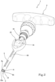
Figure 1 shows a front view of a surgical tool in accordance with this invention; -
Figure 2 shows a perspective view of the surgical tool shown inFigure 1 ; -
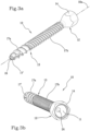
Figures 3a and 3b show two perspective views of the surgical device in accordance with this invention; -
Figure 4 shows a perspective view of a kit for positioning a surgical device via a surgical tool in accordance with this invention; -
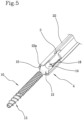
Figure 5 shows an enlarged and partially sectioned detail of the kit illustrated inFigure 4 ; -
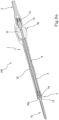
Figure 6a shows a sectioned perspective view along the development axis of the kit shown inFigure 4 ; -
Figure 6b shows an enlarged view of a detail fromFigure 6a ; -
Figure 7 shows an example of a surgical instrument that can be coupled with the device that is the subject of this invention. - In the above figures, the
number 1 designates in its entirety a surgical tool for the positioning of a surgical device, according to this invention. - The
surgical tool 1 comprises agripping portion 2 from which arod 3 extends along a main development direction X coinciding with theaxis 1a of thetool 1. Therod 3 extends from thegripping portion 2 up to its ownfree end 3a. - The
tool 1 also comprises a coupling system 4 adapted to be coupled with asurgical device 10, represented inFigures 3a and 3b , which can be engaged with a patient and is operatively active at thefree end 3a of saidrod 3. - The
surgical device 10 is, for example, a tapping attachment or a polyaxial screw and has a grippinghead 12 and astem 13. - As shown in
Figures 3a and 3b , the grippinghead 12 is shaped so as to connect with the above-mentioned coupling system 4. In particular, it has asemispherical cavity 11 adapted to be engaged with an axial retention assembly 5 of the coupling system 4 of thesurgical tool 1, as described below. In addition, the grippinghead 12 also has a polygonalexternal profile 14 adapted to be engaged with a rotational engagingassembly 16 of the coupling system 4, having a corresponding polygonalinternal profile 15, as will be described below in more detail. - The
surgical device 10, in addition, comprises astem 17 having a first 17a and a second 17b external thread. The first 17a and the second 17b external threads have different pitches from each other: in particular, thefirst thread 17a, the one closest to the free end 17' of the stem, opposite to thehead 12, is greater than thesecond thread 17b interposed between thefirst thread 17a and thehead 12 of the surgical device. - In the case of tapping, in fact, there is the need to make a first penetration into the bone having a thread with a larger pitch so as to have a higher feed rate equal to the revolutions of the tool. Following this, a thread with the same pitch as the screw follows, which will then be positioned in place of the tapping attachment.
- Advantageously, the tapping attachment has a central
axial cavity 24 that places thesemispherical cavity 11 in fluidic connection with the free end 17'. This centralaxial cavity 24 can be used for inserting Kirschner wires, or the like. - Returning now to the
surgical tool 1, the coupling system 4 can be engaged inside asemispherical cavity 11 present in thesurgical device 10, in particular in thesemispherical cavity 11 obtained in thehead 12 of thesurgical device 10, which can be seen inFigure 3b . - The coupling system 4 is used, when used for the first time, to ensure that the
tool 1 axially retains thedevice 10, and to prevent the device from accidentally coming out, once it has been coupled, unless the connection is deactivated. - For this purpose, the coupling system 4 comprises an axial retention assembly 5 that comprises, at the
free end 3a of saidrod 3, two oppositesemispherical portions axial notch 8 partially made along theaxis 1a of therod 3. - In other words, at the
free end 3a, therod 3 has anaxial notch 8 that divides thefree end 3a into twosemispherical portions - Internally, the
rod 3 has an axial channel inside of which acentral clutch 9 is slidably inserted. - The
central clutch 9 is selectively movable between a locking position, in which it approaches thefree end 3a of therod 3 and is interposed between the twosemispherical portions free end 3a of therod 3 and at which the twosemispherical portions surgical device 10. - The
free end 3a of therod 3, in particular the twosemispherical portions semispherical cavity 11 of thehead 12 of thesurgical device 10, slightly approaching each other. - By sliding the clutch and interposing it between the two semispherical portions, they can no longer approach each other but remain spaced apart and pushed radially outwards: this prevents the
free end 3a from coming out of thesemispherical cavity 11 of thehead 12. - In other words, by exerting a light thrust, the
free end 3a is inserted via an intervention into thesemispherical cavity 11. During this operation, the twosemispherical portions - By activating the axial retention assembly 5, the clutch is axially advanced towards the
free end 3a, interposing itself between the two semispherical portions and filling the gap between them, preventing them from approaching each other. Thus, the tool cannot come out axially from the device because to do so the two semispherical portions would have to approach each other in order to pass through the external circular edge of the semispherical cavity of the head of the surgical device. - The axial engagement between the tool and the device is thus guaranteed.
- To promote axial translation, the
central clutch 9 has a threadedportion 18 interacting with anut screw 19. - In particular, the coupling system 4 comprises a
nut screw 19 adapted to interact with the threadedportion 18 of thecentral clutch 9. In particular, as shown inFigure 1 , thenut screw 19 is integral with the grippingportion 2 of thetool 1. Thenut screw 19 can, preferably, be integral with and an integral part of the load-bearing or protective outer structure of thetool 1. To move it more easily, there are also movement means 20 directly active on thecentral clutch 9 to axially rotate it. In detail, the movement means 20 comprise a drivinghandwheel 21 integral with thecentral clutch 9. The drivinghandwheel 21 can be welded, made of one piece, or connected via aclutch pin 9. By rotating thehandwheel 21, the rotation is also transmitted to thecentral clutch 9; following the rotation, the threadedportion 18 interacts with thenut screw 19 promoting the axial translation of thecentral clutch 9 in one direction or the other. - In a second use, the coupling system 4 serves to move the
device 10, so as, for example, to promote the rotation of thedevice 10 around itsrotation axis 10a, and to position it correctly inside the patient. - In the case, therefore, of a tapping attachment or pedicle screw, the tool acts as a screwdriver to screw the surgical device into the bone.
- To achieve this second use, the coupling system 4 also comprises a rotational engaging
assembly 16. This rotational engagingassembly 16 comprises asleeve 22 protruding from the grippingportion 2 along a development direction X of the main tool up to its ownfree end 22a. - The
sleeve 22 is internally hollow and contains the above-mentionedrod 3 that slides inside it. - The
sleeve 22, at itsfree end 22a, has a polygonalinternal profile 15 that can be engaged with thesurgical device 1. In particular, the polygonalinternal profile 15 of thesleeve 22 can be engaged with the polygonalexternal profile 14 of thehead 12 of thesurgical device 10. - The set of the
surgical tool 1 and of at least onesurgical device 10, in accordance with what is described in this invention, defines akit 100 for positioning a surgical device. - In use, when the surgeon has to position a surgical device, such as a tapping attachment or a pedicle screw, which has to be positioned inside a bone, they prepare the
tool 1 by first acting on the drivinghandwheel 21, so that thecentral clutch 9 is moved away from thefree end 3a of therod 3. Thus, the clutch is not interposed between the twosemispherical portions semispherical cavity 11 of thehead 12. - The surgeon then connects the
head 12 of the device to the coupling system 4, in particular they insert thefree end 3a of therod 3 of the axial retention assembly 5 into thesemispherical cavity 11 of thehead 12, exerting slight pressure. - The polygonal
external profile 14 of thehead 12 is inserted inside thefree end 22a of thesleeve 22, matching the polygonalinternal profile 15 of thefree end 22a of the sleeve itself. - At this point, the surgeon acts again on the
handwheel 21 by rotating it. The screw-leadscrew coupling between the threadedportion 18 of thecentral clutch 9 and thenut screw 19 connected to the gripping portion of the tool transforms the rotation of thehandwheel 21 into an axial translation of thecentral clutch 9. Using thehandwheel 21, thecentral clutch 9 advances towards thefree end 3a of therod 3, interposing itself between the twosemispherical portions rod 3. The presence of thecentral clutch 9 between the twosemispherical portions - Once the axial engagement is assured, the tool can be used as a normal screwdriver: the coupling between the two external and internal polygonal profiles respectively of the device head and of the sleeve ensures the rotational engagement: by rotating the tool, the device is also rotated, which can be screwed into its seat.
- Once the device is inserted into the bone, the tool can be removed by acting again on the movement means, then on the handwheel, which moves the clutch away from the free end of the rod, making the two semispherical portions free, again, to approach each other. By pulling the tool with a light force, it detaches itself from the device.
- The particular constraint and connection mechanism between the head of the surgical device, and in particular the semispherical cavity present in the device head, and the particular geometry of the axial retention assembly comprising the two semispherical portions, is adapted to easily act on the devices placed in position with subsequent surgical manoeuvres, without the need to remove, for example, the tapping attachment and to immediately position the pedicle screw.
- In fact, during a normal surgical operation that involves, for example, the distraction of two vertebrae, usually at least a couple of tapping attachments are inserted to make respective holes that are then removed to be replaced by pedicle screws. The retractor acts on the screws with many drawbacks due to the larger size of the screw heads and an unstable interaction between retractors and screws.
- By instead adopting the engagement system described in this invention - in particular the use of surgical devices comprising heads equipped with semispherical cavities and tools with tips with two semispherical portions, adapted for being inserted by interlocking inside the semispherical cavity - the drawbacks encountered in the previous technique are resolved.
- One example of such a surgical tool is shown in
Figure 7 , where aretractor 200 is represented the tips of which are each made with two semispherical portions adapted for being inserted inside devices such as the one covered by this invention. The retractor may also comprise the axial retention assembly, not shown inFigure 7 . - The interaction between the tool and the device ensures the very important axial engagement for the installation of the device itself, avoiding the need for preliminary manual manoeuvres to position the tapping attachment or the screw.
- This makes it possible to create an axial engagement between the tool and the device, so that the device becomes an extension of the tool, greatly facilitating operations for the surgeon.
- The special shape of the head of the device allows the device to be used for subsequent standard surgical manoeuvres as well, without the need to remove the first device, with the risk of blood loss, to position the device designed for subsequent surgical manoeuvres. In detail, a tapping attachment can also be used for distraction manoeuvres between vertebrae using a retractor equipped with a tip designed to interact with the head of the tapping device already positioned.
Claims (10)
- A surgical tool for positioning a surgical device (10) comprising- a gripping portion (2);- a rod (3) protruding from said gripping portion (2) along a main development direction (X) of the tool up to a free end (3a) thereof;- a coupling system (4) adapted to be coupled to the surgical device (10) which can be engaged with a patient and operatively active at said free end (3a); said coupling system (4) comprising an axial retention assembly (5) comprising, at said free end (3a) of said rod (3), two opposite semispherical portions (6a, 6b), facing each other for the respective flat surfaces (7), separated from each other by an axial notch (8) made partially along said rod (3), and a central clutch (9) which is selectively movable between a locking position, in which the central clutch (9) approaches the free end (3a) of said rod (3) and interposed between the two semispherical portions (6a, 6b), preventing the reciprocal approach thereof so as to block said two semispherical portions (6a, 6b) within a seat of said surgical device (10), and a disengagement position, in which the central clutch (9) moves away from the free end (3a) of said rod (3) and at which the two semispherical portions (6a, 6b) can approach to allow said tool to come out of the surgical device (10); characterized in that said coupling system (4) comprises a rotational engaging assembly (16) comprising a sleeve (22) containing said rod (3) inside, protruding from said gripping portion (2) along a main development direction (X) of the tool up to a free end (22a) thereof which has a polygonal internal profile (15) which can be engaged with said surgical device (10).
- A surgical tool according to the preceding claim, characterized in that said coupling system (4) comprises a nut screw (19) adapted to interact on a threaded portion (18) of said central clutch (9) to promote the axial translation thereof.
- A surgical tool according to the preceding claim, characterized in that said nut screw (19) is integral with said gripping portion (2).
- A surgical tool according to one of the preceding claims, characterized in that it comprises movement means (20) which are directly active on said central clutch (9) to axially rotate it.
- A surgical tool according to the preceding claim, characterized in that said movement means (20) comprise a driving handwheel (21) which is integral with said central clutch (9).
- A surgical device comprising a gripping head (12) having a semispherical cavity (11) adapted to be engaged with a coupling system (4) of a surgical tool (1) according to one or more of the claims from 1 to 5.
- A surgical device according to the preceding claim, characterized in that said gripping head (12) has a polygonal external profile (14), adapted to be engaged with a corresponding polygonal internal profile (15) of a coupling system (4) of the surgical tool (1) according to one or more of the claims from 1 to 5.
- A surgical device according to claim 6 or 7, characterized in that it has a stem (13) with a first (17a) and a second (17b) external thread.
- A surgical device according to the preceding claim, characterized in that said first (17a) and second (17b) external threads have mutually different pitches.
- A kit (100) for positioning a surgical device comprising:- a surgical tool (1) for positioning a surgical device (10) according to any one of the claims from 1 to 5;- at least one surgical device (10) provided with a head (12) which can be coupled to the coupling system (4) of said surgical tool (1).
Applications Claiming Priority (2)
| Application Number | Priority Date | Filing Date | Title |
|---|---|---|---|
| IT102018000010562A IT201800010562A1 (en) | 2018-11-26 | 2018-11-26 | SURGICAL TOOL FOR POSITIONING A SURGICAL DEVICE AND SURGICAL DEVICE AND KIT FOR THE POSITIONING OF SAID SURGICAL DEVICE |
| PCT/IB2019/060020 WO2020109940A1 (en) | 2018-11-26 | 2019-11-21 | Surgical tool for positioning a surgical device, surgical device and kit |
Publications (2)
| Publication Number | Publication Date |
|---|---|
| EP3886742A1 EP3886742A1 (en) | 2021-10-06 |
| EP3886742B1 true EP3886742B1 (en) | 2024-03-13 |
Family
ID=65409410
Family Applications (1)
| Application Number | Title | Priority Date | Filing Date |
|---|---|---|---|
| EP19805508.9A Active EP3886742B1 (en) | 2018-11-26 | 2019-11-21 | Surgical tool for positioning a surgical device, surgical device and kit |
Country Status (7)
| Country | Link |
|---|---|
| US (2) | US11950821B2 (en) |
| EP (1) | EP3886742B1 (en) |
| JP (1) | JP7135212B2 (en) |
| AU (1) | AU2019389876B2 (en) |
| ES (1) | ES2984040T3 (en) |
| IT (1) | IT201800010562A1 (en) |
| WO (1) | WO2020109940A1 (en) |
Families Citing this family (2)
| Publication number | Priority date | Publication date | Assignee | Title |
|---|---|---|---|---|
| EP4088674B1 (en) * | 2021-05-12 | 2023-11-29 | Biedermann Technologies GmbH & Co. KG | Instrument for use in surgery |
| US12318125B2 (en) * | 2021-09-11 | 2025-06-03 | Biofusion Management and Manufacturing, LLC | Variable head driver for use with surgical implants |
Family Cites Families (13)
| Publication number | Priority date | Publication date | Assignee | Title |
|---|---|---|---|---|
| JPS5953017U (en) * | 1982-09-30 | 1984-04-07 | 瑞穂医科工業株式会社 | Intramedullary driving rod horizontal set screw driver |
| US20040147928A1 (en) * | 2002-10-30 | 2004-07-29 | Landry Michael E. | Spinal stabilization system using flexible members |
| US7811288B2 (en) * | 2004-12-02 | 2010-10-12 | Zimmer Spine, Inc. | Instruments and methods for adjusting separation distance of vertebral bodies with a minimally invasive spinal stabilization procedure |
| US7331263B2 (en) * | 2006-03-31 | 2008-02-19 | Sdgi Holdings, Inc. | Surgical screwdrivers with torque control and methods of use |
| US8048129B2 (en) * | 2007-08-15 | 2011-11-01 | Zimmer Spine, Inc. | MIS crosslink apparatus and methods for spinal implant |
| US7947064B2 (en) * | 2007-11-28 | 2011-05-24 | Zimmer Spine, Inc. | Stabilization system and method |
| US9801667B2 (en) * | 2007-12-07 | 2017-10-31 | Nexus Spine, L.L.C. | Instruments, tools, and methods for presson pedicle screws |
| US8900240B2 (en) * | 2010-02-12 | 2014-12-02 | Pioneer Surgical Technology, Inc. | Spinal rod and screw securing apparatus and method |
| US20110257690A1 (en) * | 2010-04-20 | 2011-10-20 | Warsaw Orthopedic, Inc. | Transverse and Sagittal Adjusting Screw |
| US20120247284A1 (en) * | 2011-03-28 | 2012-10-04 | Synthes Usa, Llc | Interlock driving instrument |
| US20130150864A1 (en) * | 2011-12-12 | 2013-06-13 | Warsaw Orthopedic, Inc. | Surgical instrument and method |
| US20150250521A1 (en) * | 2012-10-18 | 2015-09-10 | Deroyal Industries Inc. | Driver Apparatus For A Pedicle Screw Assembly |
| US10363073B2 (en) * | 2016-07-13 | 2019-07-30 | Medos International Sàrl | Bone anchor assemblies and related instrumentation |
-
2018
- 2018-11-26 IT IT102018000010562A patent/IT201800010562A1/en unknown
-
2019
- 2019-11-21 EP EP19805508.9A patent/EP3886742B1/en active Active
- 2019-11-21 AU AU2019389876A patent/AU2019389876B2/en active Active
- 2019-11-21 US US17/297,096 patent/US11950821B2/en active Active
- 2019-11-21 JP JP2021529384A patent/JP7135212B2/en active Active
- 2019-11-21 WO PCT/IB2019/060020 patent/WO2020109940A1/en not_active Ceased
- 2019-11-21 ES ES19805508T patent/ES2984040T3/en active Active
-
2024
- 2024-04-02 US US18/625,079 patent/US12575870B2/en active Active
Also Published As
| Publication number | Publication date |
|---|---|
| US20220008109A1 (en) | 2022-01-13 |
| US11950821B2 (en) | 2024-04-09 |
| AU2019389876A1 (en) | 2021-06-10 |
| US12575870B2 (en) | 2026-03-17 |
| ES2984040T3 (en) | 2024-10-28 |
| AU2019389876B2 (en) | 2022-08-11 |
| WO2020109940A1 (en) | 2020-06-04 |
| US20240245440A1 (en) | 2024-07-25 |
| IT201800010562A1 (en) | 2020-05-26 |
| EP3886742A1 (en) | 2021-10-06 |
| JP7135212B2 (en) | 2022-09-12 |
| JP2022511758A (en) | 2022-02-01 |
Similar Documents
| Publication | Publication Date | Title |
|---|---|---|
| US12575870B2 (en) | Surgical tool for positioning a surgical device, surgical device and kit | |
| EP4272686B1 (en) | Bone anchor assemblies and related instrumentation | |
| US10874438B2 (en) | Bone anchor assemblies and related instrumentation | |
| EP2881056B1 (en) | Extension device for a bone anchor, in particular for minimally invasive surgery | |
| CN110494090B (en) | Bone anchor assemblies and related instruments | |
| US10463402B2 (en) | Bone anchor assemblies and related instrumentation | |
| US9254160B2 (en) | Driver assembly with guidewire control mechanism | |
| EP2896378A1 (en) | Quick-lock driver for a bone screw | |
| EP2772212B1 (en) | Instrument for inserting a bone anchoring element and system of such an instrument and a polyaxial bone anchoring element | |
| US10390967B2 (en) | Inserter guide and driver system | |
| JP2019516467A (en) | Medical device for temporarily fastening multiaxial pedicle screws | |
| JP2007512100A (en) | Cannula fastener system | |
| US12004783B2 (en) | Instrument for use in surgery | |
| EP2906132B1 (en) | Fixing means for fixation of bone fragments at bone fractures | |
| EP3838197B1 (en) | Instrument for use with a bone anchoring device |
Legal Events
| Date | Code | Title | Description |
|---|---|---|---|
| STAA | Information on the status of an ep patent application or granted ep patent |
Free format text: STATUS: UNKNOWN |
|
| STAA | Information on the status of an ep patent application or granted ep patent |
Free format text: STATUS: THE INTERNATIONAL PUBLICATION HAS BEEN MADE |
|
| PUAI | Public reference made under article 153(3) epc to a published international application that has entered the european phase |
Free format text: ORIGINAL CODE: 0009012 |
|
| STAA | Information on the status of an ep patent application or granted ep patent |
Free format text: STATUS: REQUEST FOR EXAMINATION WAS MADE |
|
| 17P | Request for examination filed |
Effective date: 20210422 |
|
| AK | Designated contracting states |
Kind code of ref document: A1 Designated state(s): AL AT BE BG CH CY CZ DE DK EE ES FI FR GB GR HR HU IE IS IT LI LT LU LV MC MK MT NL NO PL PT RO RS SE SI SK SM TR |
|
| DAV | Request for validation of the european patent (deleted) | ||
| DAX | Request for extension of the european patent (deleted) | ||
| P01 | Opt-out of the competence of the unified patent court (upc) registered |
Effective date: 20230630 |
|
| RIC1 | Information provided on ipc code assigned before grant |
Ipc: A61B 17/88 20060101ALI20230821BHEP Ipc: A61B 17/86 20060101ALI20230821BHEP Ipc: A61B 17/16 20060101ALI20230821BHEP Ipc: A61B 17/70 20060101AFI20230821BHEP |
|
| GRAP | Despatch of communication of intention to grant a patent |
Free format text: ORIGINAL CODE: EPIDOSNIGR1 |
|
| STAA | Information on the status of an ep patent application or granted ep patent |
Free format text: STATUS: GRANT OF PATENT IS INTENDED |
|
| INTG | Intention to grant announced |
Effective date: 20231011 |
|
| GRAS | Grant fee paid |
Free format text: ORIGINAL CODE: EPIDOSNIGR3 |
|
| GRAA | (expected) grant |
Free format text: ORIGINAL CODE: 0009210 |
|
| STAA | Information on the status of an ep patent application or granted ep patent |
Free format text: STATUS: THE PATENT HAS BEEN GRANTED |
|
| AK | Designated contracting states |
Kind code of ref document: B1 Designated state(s): AL AT BE BG CH CY CZ DE DK EE ES FI FR GB GR HR HU IE IS IT LI LT LU LV MC MK MT NL NO PL PT RO RS SE SI SK SM TR |
|
| REG | Reference to a national code |
Ref country code: GB Ref legal event code: FG4D |
|
| REG | Reference to a national code |
Ref country code: CH Ref legal event code: EP |
|
| REG | Reference to a national code |
Ref country code: DE Ref legal event code: R096 Ref document number: 602019048296 Country of ref document: DE |
|
| REG | Reference to a national code |
Ref country code: IE Ref legal event code: FG4D |
|
| PG25 | Lapsed in a contracting state [announced via postgrant information from national office to epo] |
Ref country code: LT Free format text: LAPSE BECAUSE OF FAILURE TO SUBMIT A TRANSLATION OF THE DESCRIPTION OR TO PAY THE FEE WITHIN THE PRESCRIBED TIME-LIMIT Effective date: 20240313 |
|
| REG | Reference to a national code |
Ref country code: LT Ref legal event code: MG9D |
|
| PG25 | Lapsed in a contracting state [announced via postgrant information from national office to epo] |
Ref country code: GR Free format text: LAPSE BECAUSE OF FAILURE TO SUBMIT A TRANSLATION OF THE DESCRIPTION OR TO PAY THE FEE WITHIN THE PRESCRIBED TIME-LIMIT Effective date: 20240614 |
|
| REG | Reference to a national code |
Ref country code: NL Ref legal event code: MP Effective date: 20240313 |
|
| PG25 | Lapsed in a contracting state [announced via postgrant information from national office to epo] |
Ref country code: RS Free format text: LAPSE BECAUSE OF FAILURE TO SUBMIT A TRANSLATION OF THE DESCRIPTION OR TO PAY THE FEE WITHIN THE PRESCRIBED TIME-LIMIT Effective date: 20240613 Ref country code: HR Free format text: LAPSE BECAUSE OF FAILURE TO SUBMIT A TRANSLATION OF THE DESCRIPTION OR TO PAY THE FEE WITHIN THE PRESCRIBED TIME-LIMIT Effective date: 20240313 |
|
| PG25 | Lapsed in a contracting state [announced via postgrant information from national office to epo] |
Ref country code: RS Free format text: LAPSE BECAUSE OF FAILURE TO SUBMIT A TRANSLATION OF THE DESCRIPTION OR TO PAY THE FEE WITHIN THE PRESCRIBED TIME-LIMIT Effective date: 20240613 Ref country code: NO Free format text: LAPSE BECAUSE OF FAILURE TO SUBMIT A TRANSLATION OF THE DESCRIPTION OR TO PAY THE FEE WITHIN THE PRESCRIBED TIME-LIMIT Effective date: 20240613 Ref country code: LT Free format text: LAPSE BECAUSE OF FAILURE TO SUBMIT A TRANSLATION OF THE DESCRIPTION OR TO PAY THE FEE WITHIN THE PRESCRIBED TIME-LIMIT Effective date: 20240313 Ref country code: HR Free format text: LAPSE BECAUSE OF FAILURE TO SUBMIT A TRANSLATION OF THE DESCRIPTION OR TO PAY THE FEE WITHIN THE PRESCRIBED TIME-LIMIT Effective date: 20240313 Ref country code: GR Free format text: LAPSE BECAUSE OF FAILURE TO SUBMIT A TRANSLATION OF THE DESCRIPTION OR TO PAY THE FEE WITHIN THE PRESCRIBED TIME-LIMIT Effective date: 20240614 Ref country code: FI Free format text: LAPSE BECAUSE OF FAILURE TO SUBMIT A TRANSLATION OF THE DESCRIPTION OR TO PAY THE FEE WITHIN THE PRESCRIBED TIME-LIMIT Effective date: 20240313 Ref country code: BG Free format text: LAPSE BECAUSE OF FAILURE TO SUBMIT A TRANSLATION OF THE DESCRIPTION OR TO PAY THE FEE WITHIN THE PRESCRIBED TIME-LIMIT Effective date: 20240313 |
|
| REG | Reference to a national code |
Ref country code: AT Ref legal event code: MK05 Ref document number: 1665007 Country of ref document: AT Kind code of ref document: T Effective date: 20240313 |
|
| PG25 | Lapsed in a contracting state [announced via postgrant information from national office to epo] |
Ref country code: SE Free format text: LAPSE BECAUSE OF FAILURE TO SUBMIT A TRANSLATION OF THE DESCRIPTION OR TO PAY THE FEE WITHIN THE PRESCRIBED TIME-LIMIT Effective date: 20240313 Ref country code: LV Free format text: LAPSE BECAUSE OF FAILURE TO SUBMIT A TRANSLATION OF THE DESCRIPTION OR TO PAY THE FEE WITHIN THE PRESCRIBED TIME-LIMIT Effective date: 20240313 |
|
| PG25 | Lapsed in a contracting state [announced via postgrant information from national office to epo] |
Ref country code: NL Free format text: LAPSE BECAUSE OF FAILURE TO SUBMIT A TRANSLATION OF THE DESCRIPTION OR TO PAY THE FEE WITHIN THE PRESCRIBED TIME-LIMIT Effective date: 20240313 |
|
| PG25 | Lapsed in a contracting state [announced via postgrant information from national office to epo] |
Ref country code: NL Free format text: LAPSE BECAUSE OF FAILURE TO SUBMIT A TRANSLATION OF THE DESCRIPTION OR TO PAY THE FEE WITHIN THE PRESCRIBED TIME-LIMIT Effective date: 20240313 |
|
| PG25 | Lapsed in a contracting state [announced via postgrant information from national office to epo] |
Ref country code: IS Free format text: LAPSE BECAUSE OF FAILURE TO SUBMIT A TRANSLATION OF THE DESCRIPTION OR TO PAY THE FEE WITHIN THE PRESCRIBED TIME-LIMIT Effective date: 20240713 |
|
| PG25 | Lapsed in a contracting state [announced via postgrant information from national office to epo] |
Ref country code: SM Free format text: LAPSE BECAUSE OF FAILURE TO SUBMIT A TRANSLATION OF THE DESCRIPTION OR TO PAY THE FEE WITHIN THE PRESCRIBED TIME-LIMIT Effective date: 20240313 Ref country code: PT Free format text: LAPSE BECAUSE OF FAILURE TO SUBMIT A TRANSLATION OF THE DESCRIPTION OR TO PAY THE FEE WITHIN THE PRESCRIBED TIME-LIMIT Effective date: 20240715 |
|
| PG25 | Lapsed in a contracting state [announced via postgrant information from national office to epo] |
Ref country code: EE Free format text: LAPSE BECAUSE OF FAILURE TO SUBMIT A TRANSLATION OF THE DESCRIPTION OR TO PAY THE FEE WITHIN THE PRESCRIBED TIME-LIMIT Effective date: 20240313 Ref country code: CZ Free format text: LAPSE BECAUSE OF FAILURE TO SUBMIT A TRANSLATION OF THE DESCRIPTION OR TO PAY THE FEE WITHIN THE PRESCRIBED TIME-LIMIT Effective date: 20240313 |
|
| PG25 | Lapsed in a contracting state [announced via postgrant information from national office to epo] |
Ref country code: AT Free format text: LAPSE BECAUSE OF FAILURE TO SUBMIT A TRANSLATION OF THE DESCRIPTION OR TO PAY THE FEE WITHIN THE PRESCRIBED TIME-LIMIT Effective date: 20240313 |
|
| PG25 | Lapsed in a contracting state [announced via postgrant information from national office to epo] |
Ref country code: PL Free format text: LAPSE BECAUSE OF FAILURE TO SUBMIT A TRANSLATION OF THE DESCRIPTION OR TO PAY THE FEE WITHIN THE PRESCRIBED TIME-LIMIT Effective date: 20240313 |
|
| REG | Reference to a national code |
Ref country code: ES Ref legal event code: FG2A Ref document number: 2984040 Country of ref document: ES Kind code of ref document: T3 Effective date: 20241028 |
|
| PG25 | Lapsed in a contracting state [announced via postgrant information from national office to epo] |
Ref country code: SK Free format text: LAPSE BECAUSE OF FAILURE TO SUBMIT A TRANSLATION OF THE DESCRIPTION OR TO PAY THE FEE WITHIN THE PRESCRIBED TIME-LIMIT Effective date: 20240313 |
|
| PG25 | Lapsed in a contracting state [announced via postgrant information from national office to epo] |
Ref country code: SM Free format text: LAPSE BECAUSE OF FAILURE TO SUBMIT A TRANSLATION OF THE DESCRIPTION OR TO PAY THE FEE WITHIN THE PRESCRIBED TIME-LIMIT Effective date: 20240313 Ref country code: SK Free format text: LAPSE BECAUSE OF FAILURE TO SUBMIT A TRANSLATION OF THE DESCRIPTION OR TO PAY THE FEE WITHIN THE PRESCRIBED TIME-LIMIT Effective date: 20240313 Ref country code: RO Free format text: LAPSE BECAUSE OF FAILURE TO SUBMIT A TRANSLATION OF THE DESCRIPTION OR TO PAY THE FEE WITHIN THE PRESCRIBED TIME-LIMIT Effective date: 20240313 Ref country code: PT Free format text: LAPSE BECAUSE OF FAILURE TO SUBMIT A TRANSLATION OF THE DESCRIPTION OR TO PAY THE FEE WITHIN THE PRESCRIBED TIME-LIMIT Effective date: 20240715 Ref country code: PL Free format text: LAPSE BECAUSE OF FAILURE TO SUBMIT A TRANSLATION OF THE DESCRIPTION OR TO PAY THE FEE WITHIN THE PRESCRIBED TIME-LIMIT Effective date: 20240313 Ref country code: IS Free format text: LAPSE BECAUSE OF FAILURE TO SUBMIT A TRANSLATION OF THE DESCRIPTION OR TO PAY THE FEE WITHIN THE PRESCRIBED TIME-LIMIT Effective date: 20240713 Ref country code: EE Free format text: LAPSE BECAUSE OF FAILURE TO SUBMIT A TRANSLATION OF THE DESCRIPTION OR TO PAY THE FEE WITHIN THE PRESCRIBED TIME-LIMIT Effective date: 20240313 Ref country code: CZ Free format text: LAPSE BECAUSE OF FAILURE TO SUBMIT A TRANSLATION OF THE DESCRIPTION OR TO PAY THE FEE WITHIN THE PRESCRIBED TIME-LIMIT Effective date: 20240313 Ref country code: AT Free format text: LAPSE BECAUSE OF FAILURE TO SUBMIT A TRANSLATION OF THE DESCRIPTION OR TO PAY THE FEE WITHIN THE PRESCRIBED TIME-LIMIT Effective date: 20240313 |
|
| REG | Reference to a national code |
Ref country code: DE Ref legal event code: R097 Ref document number: 602019048296 Country of ref document: DE |
|
| PG25 | Lapsed in a contracting state [announced via postgrant information from national office to epo] |
Ref country code: DK Free format text: LAPSE BECAUSE OF FAILURE TO SUBMIT A TRANSLATION OF THE DESCRIPTION OR TO PAY THE FEE WITHIN THE PRESCRIBED TIME-LIMIT Effective date: 20240313 |
|
| PLBE | No opposition filed within time limit |
Free format text: ORIGINAL CODE: 0009261 |
|
| STAA | Information on the status of an ep patent application or granted ep patent |
Free format text: STATUS: NO OPPOSITION FILED WITHIN TIME LIMIT |
|
| PG25 | Lapsed in a contracting state [announced via postgrant information from national office to epo] |
Ref country code: DK Free format text: LAPSE BECAUSE OF FAILURE TO SUBMIT A TRANSLATION OF THE DESCRIPTION OR TO PAY THE FEE WITHIN THE PRESCRIBED TIME-LIMIT Effective date: 20240313 |
|
| 26N | No opposition filed |
Effective date: 20241216 |
|
| PG25 | Lapsed in a contracting state [announced via postgrant information from national office to epo] |
Ref country code: SI Free format text: LAPSE BECAUSE OF FAILURE TO SUBMIT A TRANSLATION OF THE DESCRIPTION OR TO PAY THE FEE WITHIN THE PRESCRIBED TIME-LIMIT Effective date: 20240313 |
|
| PG25 | Lapsed in a contracting state [announced via postgrant information from national office to epo] |
Ref country code: MC Free format text: LAPSE BECAUSE OF FAILURE TO SUBMIT A TRANSLATION OF THE DESCRIPTION OR TO PAY THE FEE WITHIN THE PRESCRIBED TIME-LIMIT Effective date: 20240313 |
|
| PG25 | Lapsed in a contracting state [announced via postgrant information from national office to epo] |
Ref country code: LU Free format text: LAPSE BECAUSE OF NON-PAYMENT OF DUE FEES Effective date: 20241121 |
|
| REG | Reference to a national code |
Ref country code: BE Ref legal event code: MM Effective date: 20241130 |
|
| PG25 | Lapsed in a contracting state [announced via postgrant information from national office to epo] |
Ref country code: BE Free format text: LAPSE BECAUSE OF NON-PAYMENT OF DUE FEES Effective date: 20241130 |
|
| PG25 | Lapsed in a contracting state [announced via postgrant information from national office to epo] |
Ref country code: IE Free format text: LAPSE BECAUSE OF NON-PAYMENT OF DUE FEES Effective date: 20241121 |
|
| REG | Reference to a national code |
Ref country code: CH Ref legal event code: U11 Free format text: ST27 STATUS EVENT CODE: U-0-0-U10-U11 (AS PROVIDED BY THE NATIONAL OFFICE) Effective date: 20251201 |
|
| PGFP | Annual fee paid to national office [announced via postgrant information from national office to epo] |
Ref country code: DE Payment date: 20251126 Year of fee payment: 7 |
|
| PGFP | Annual fee paid to national office [announced via postgrant information from national office to epo] |
Ref country code: GB Payment date: 20251125 Year of fee payment: 7 |
|
| PGFP | Annual fee paid to national office [announced via postgrant information from national office to epo] |
Ref country code: IT Payment date: 20251127 Year of fee payment: 7 |
|
| PGFP | Annual fee paid to national office [announced via postgrant information from national office to epo] |
Ref country code: FR Payment date: 20251124 Year of fee payment: 7 |
|
| PGFP | Annual fee paid to national office [announced via postgrant information from national office to epo] |
Ref country code: CH Payment date: 20251201 Year of fee payment: 7 |
|
| PGFP | Annual fee paid to national office [announced via postgrant information from national office to epo] |
Ref country code: ES Payment date: 20251209 Year of fee payment: 7 |
|
| PG25 | Lapsed in a contracting state [announced via postgrant information from national office to epo] |
Ref country code: HU Free format text: LAPSE BECAUSE OF FAILURE TO SUBMIT A TRANSLATION OF THE DESCRIPTION OR TO PAY THE FEE WITHIN THE PRESCRIBED TIME-LIMIT; INVALID AB INITIO Effective date: 20191121 |
|
| PG25 | Lapsed in a contracting state [announced via postgrant information from national office to epo] |
Ref country code: CY Free format text: LAPSE BECAUSE OF FAILURE TO SUBMIT A TRANSLATION OF THE DESCRIPTION OR TO PAY THE FEE WITHIN THE PRESCRIBED TIME-LIMIT; INVALID AB INITIO Effective date: 20191121 |