EP3886735B1 - Disposable acetabular modular reamer and method of manufaturing - Google Patents
Disposable acetabular modular reamer and method of manufaturing Download PDFInfo
- Publication number
- EP3886735B1 EP3886735B1 EP19824127.5A EP19824127A EP3886735B1 EP 3886735 B1 EP3886735 B1 EP 3886735B1 EP 19824127 A EP19824127 A EP 19824127A EP 3886735 B1 EP3886735 B1 EP 3886735B1
- Authority
- EP
- European Patent Office
- Prior art keywords
- arcuate
- apex
- extending
- reamer head
- apex region
- Prior art date
- Legal status (The legal status is an assumption and is not a legal conclusion. Google has not performed a legal analysis and makes no representation as to the accuracy of the status listed.)
- Active
Links
Images




Classifications
-
- A—HUMAN NECESSITIES
- A61—MEDICAL OR VETERINARY SCIENCE; HYGIENE
- A61B—DIAGNOSIS; SURGERY; IDENTIFICATION
- A61B17/00—Surgical instruments, devices or methods
- A61B17/16—Instruments for performing osteoclasis; Drills or chisels for bones; Trepans
- A61B17/1613—Component parts
- A61B17/1615—Drill bits, i.e. rotating tools extending from a handpiece to contact the worked material
- A61B17/1617—Drill bits, i.e. rotating tools extending from a handpiece to contact the worked material with mobile or detachable parts
-
- A—HUMAN NECESSITIES
- A61—MEDICAL OR VETERINARY SCIENCE; HYGIENE
- A61B—DIAGNOSIS; SURGERY; IDENTIFICATION
- A61B17/00—Surgical instruments, devices or methods
- A61B17/16—Instruments for performing osteoclasis; Drills or chisels for bones; Trepans
- A61B17/1642—Instruments for performing osteoclasis; Drills or chisels for bones; Trepans for producing a curved bore
-
- A—HUMAN NECESSITIES
- A61—MEDICAL OR VETERINARY SCIENCE; HYGIENE
- A61F—FILTERS IMPLANTABLE INTO BLOOD VESSELS; PROSTHESES; DEVICES PROVIDING PATENCY TO, OR PREVENTING COLLAPSING OF, TUBULAR STRUCTURES OF THE BODY, e.g. STENTS; ORTHOPAEDIC, NURSING OR CONTRACEPTIVE DEVICES; FOMENTATION; TREATMENT OR PROTECTION OF EYES OR EARS; BANDAGES, DRESSINGS OR ABSORBENT PADS; FIRST-AID KITS
- A61F2/00—Filters implantable into blood vessels; Prostheses, i.e. artificial substitutes or replacements for parts of the body; Appliances for connecting them with the body; Devices providing patency to, or preventing collapsing of, tubular structures of the body, e.g. stents
- A61F2/02—Prostheses implantable into the body
- A61F2/30—Joints
- A61F2/46—Special tools for implanting artificial joints
- A61F2/4603—Special tools for implanting artificial joints for insertion or extraction of endoprosthetic joints or of accessories thereof
-
- A—HUMAN NECESSITIES
- A61—MEDICAL OR VETERINARY SCIENCE; HYGIENE
- A61F—FILTERS IMPLANTABLE INTO BLOOD VESSELS; PROSTHESES; DEVICES PROVIDING PATENCY TO, OR PREVENTING COLLAPSING OF, TUBULAR STRUCTURES OF THE BODY, e.g. STENTS; ORTHOPAEDIC, NURSING OR CONTRACEPTIVE DEVICES; FOMENTATION; TREATMENT OR PROTECTION OF EYES OR EARS; BANDAGES, DRESSINGS OR ABSORBENT PADS; FIRST-AID KITS
- A61F2/00—Filters implantable into blood vessels; Prostheses, i.e. artificial substitutes or replacements for parts of the body; Appliances for connecting them with the body; Devices providing patency to, or preventing collapsing of, tubular structures of the body, e.g. stents
- A61F2/02—Prostheses implantable into the body
- A61F2/30—Joints
- A61F2/46—Special tools for implanting artificial joints
- A61F2/4603—Special tools for implanting artificial joints for insertion or extraction of endoprosthetic joints or of accessories thereof
- A61F2/4609—Special tools for implanting artificial joints for insertion or extraction of endoprosthetic joints or of accessories thereof of acetabular cups
-
- A—HUMAN NECESSITIES
- A61—MEDICAL OR VETERINARY SCIENCE; HYGIENE
- A61F—FILTERS IMPLANTABLE INTO BLOOD VESSELS; PROSTHESES; DEVICES PROVIDING PATENCY TO, OR PREVENTING COLLAPSING OF, TUBULAR STRUCTURES OF THE BODY, e.g. STENTS; ORTHOPAEDIC, NURSING OR CONTRACEPTIVE DEVICES; FOMENTATION; TREATMENT OR PROTECTION OF EYES OR EARS; BANDAGES, DRESSINGS OR ABSORBENT PADS; FIRST-AID KITS
- A61F2/00—Filters implantable into blood vessels; Prostheses, i.e. artificial substitutes or replacements for parts of the body; Appliances for connecting them with the body; Devices providing patency to, or preventing collapsing of, tubular structures of the body, e.g. stents
- A61F2/02—Prostheses implantable into the body
- A61F2/30—Joints
- A61F2/46—Special tools for implanting artificial joints
- A61F2/4603—Special tools for implanting artificial joints for insertion or extraction of endoprosthetic joints or of accessories thereof
- A61F2/4612—Special tools for implanting artificial joints for insertion or extraction of endoprosthetic joints or of accessories thereof of shoulders
-
- A—HUMAN NECESSITIES
- A61—MEDICAL OR VETERINARY SCIENCE; HYGIENE
- A61B—DIAGNOSIS; SURGERY; IDENTIFICATION
- A61B17/00—Surgical instruments, devices or methods
- A61B17/00234—Surgical instruments, devices or methods for minimally invasive surgery
-
- A—HUMAN NECESSITIES
- A61—MEDICAL OR VETERINARY SCIENCE; HYGIENE
- A61B—DIAGNOSIS; SURGERY; IDENTIFICATION
- A61B17/00—Surgical instruments, devices or methods
- A61B17/16—Instruments for performing osteoclasis; Drills or chisels for bones; Trepans
- A61B17/1662—Instruments for performing osteoclasis; Drills or chisels for bones; Trepans for particular parts of the body
- A61B17/1664—Instruments for performing osteoclasis; Drills or chisels for bones; Trepans for particular parts of the body for the hip
- A61B17/1666—Instruments for performing osteoclasis; Drills or chisels for bones; Trepans for particular parts of the body for the hip for the acetabulum
-
- A—HUMAN NECESSITIES
- A61—MEDICAL OR VETERINARY SCIENCE; HYGIENE
- A61B—DIAGNOSIS; SURGERY; IDENTIFICATION
- A61B17/00—Surgical instruments, devices or methods
- A61B17/16—Instruments for performing osteoclasis; Drills or chisels for bones; Trepans
- A61B17/1662—Instruments for performing osteoclasis; Drills or chisels for bones; Trepans for particular parts of the body
- A61B17/1684—Instruments for performing osteoclasis; Drills or chisels for bones; Trepans for particular parts of the body for the shoulder
-
- A—HUMAN NECESSITIES
- A61—MEDICAL OR VETERINARY SCIENCE; HYGIENE
- A61B—DIAGNOSIS; SURGERY; IDENTIFICATION
- A61B17/00—Surgical instruments, devices or methods
- A61B2017/0023—Surgical instruments, devices or methods disposable
-
- A—HUMAN NECESSITIES
- A61—MEDICAL OR VETERINARY SCIENCE; HYGIENE
- A61B—DIAGNOSIS; SURGERY; IDENTIFICATION
- A61B17/00—Surgical instruments, devices or methods
- A61B2017/00526—Methods of manufacturing
-
- A—HUMAN NECESSITIES
- A61—MEDICAL OR VETERINARY SCIENCE; HYGIENE
- A61B—DIAGNOSIS; SURGERY; IDENTIFICATION
- A61B17/00—Surgical instruments, devices or methods
- A61B17/16—Instruments for performing osteoclasis; Drills or chisels for bones; Trepans
- A61B2017/1602—Mills
Definitions
- This document pertains generally, but not by way of limitation, to orthopedic devices, and, more particularly, to reamer heads and methods of manufacturing reamer heads.
- the reamer head can include a driver interface that can be attached to a universal driver.
- a driver interface that can be attached to a universal driver.
- EP2359755A1 discloses a disposable acetabular reamer designed to improve tissue removal efficiency.
- the reamer device comprises a reamer cutting shell and a reamer driver interface.
- the reamer cutting shell has a hemispherical structure with a plurality of spaced apart rib portions that extend from a central region located about an apex of the shell.
- a tissue cutting surface further extends along a longitudinal leading edge, trailing edge or both leading and trailing rib portions.
- the tissue cutting surface further comprises a series of alternating cutting teeth and notches which are bent at a rake angle.
- an orthopedic reamer head as set out in claim 1.
- Optional features are set out in claims 2 to 10.
- the surgeon can ream the bone surface using a driver that is adapted to interface with a reamer head.
- the reamer head can include cutting elements, that, when rotated by the driver, scrape the bone surface to remove bone and carry the bone away from the implant site.
- the reamer heads and methods of manufacturing described herein reduce the cost to produce the reamer head. Therefore, it can be feasible to provide the reamer head as a disposable, one-time use product.
- a disposable reamer head eliminates the need to clean and sterilize the reamer head and eliminates a source of cross-contamination between patients.
- FIGS. 1A , 1B and 2-6 show various views of an illustrative example of an orthopedic reamer head 10 and elements thereof.
- the orthopedic reamer head 10 can include a body 100 and a cutting system 200. Together the body 100 and the cutting system 200 form a reamer head 10 having a modular design.
- the shape of the body 100 when rotated, can facilitate reaming an acetabulum to prepare the acetabulum to receive an implant.
- the reamer head 10 is configured to ream a generally hemispherical shape to approximate the shape of an acetabulum or acetabular implant.
Landscapes
- Health & Medical Sciences (AREA)
- Orthopedic Medicine & Surgery (AREA)
- Life Sciences & Earth Sciences (AREA)
- Transplantation (AREA)
- Animal Behavior & Ethology (AREA)
- Oral & Maxillofacial Surgery (AREA)
- Veterinary Medicine (AREA)
- Engineering & Computer Science (AREA)
- Biomedical Technology (AREA)
- Heart & Thoracic Surgery (AREA)
- Public Health (AREA)
- General Health & Medical Sciences (AREA)
- Surgery (AREA)
- Physical Education & Sports Medicine (AREA)
- Cardiology (AREA)
- Vascular Medicine (AREA)
- Molecular Biology (AREA)
- Medical Informatics (AREA)
- Nuclear Medicine, Radiotherapy & Molecular Imaging (AREA)
- Dentistry (AREA)
- Prostheses (AREA)
- Surgical Instruments (AREA)
Description
- This application claims the benefit of
U.S. Provisional Patent Application Serial No. 62/772,736, filed on November 29, 2018 - This document pertains generally, but not by way of limitation, to orthopedic devices, and, more particularly, to reamer heads and methods of manufacturing reamer heads.
- Bone degradation, disease and injury are a common occurrence that can be treated with surgical intervention using an orthopedic device such as an orthopedic implant. Orthopedic implants can be used, for example, to replace a joint or portion of a joint, or to provide fixation to a fractured bone while it heals.
- In order to implant an orthopedic device, such as a hip implant, the surgeon can prepare the bone surface by a process such as reaming. Reaming can be accomplished using a reamer head having cutting elements thereon. The reamer head can be rotated to remove and shape the bone at the implant site. One such implant site can include an acetabulum of a hip bone, and the bone can be shaped to mimic the natural hemispherical shape of an acetabulum.
- To provide rotation for the reaming process, the reamer head can include a driver interface that can be attached to a universal driver. When the reamer head is rotated by the universal driver with the reamer head located at a bone surface, the cutting elements on the reamer head remove the bone material.
-
EP2359755A1 discloses a disposable acetabular reamer designed to improve tissue removal efficiency. The reamer device comprises a reamer cutting shell and a reamer driver interface. The reamer cutting shell has a hemispherical structure with a plurality of spaced apart rib portions that extend from a central region located about an apex of the shell. A tissue cutting surface further extends along a longitudinal leading edge, trailing edge or both leading and trailing rib portions. The tissue cutting surface further comprises a series of alternating cutting teeth and notches which are bent at a rake angle. - According to an aspect, there is provided an orthopedic reamer head as set out in
claim 1. Optional features are set out in claims 2 to 10. - According to another aspect, there is provided a method of manufacturing an orthopedic reamer head as set out in
claim 11. Optional features are set out in claims 12 to 15. - In the drawings, which are not necessarily drawn to scale, like numerals may describe similar components in different views. Like numerals having different letter suffixes may represent different instances of similar components. The drawings illustrate generally, by way of example, but not by way of limitation, various examples discussed in the present document.
-
FIG. 1A shows a perspective view of an illustrative orthopedic reamer head including a body and a cutting system, in accordance with at least one example. -
FIG. 1B shows a close-up perspective view of a portion of the reamer head ofFIG. 1A , in accordance with at least one example. -
FIG. 2 shows another perspective the reamer head ofFIG. 1A with the body shown as partially transparent and only one arcuate element shown in solid, in accordance with at least one example. -
FIG. 3 shows a cross-sectional view of the body and one arcuate element ofFIG. 1A taken along line A-A', in accordance with at least one example. -
FIG. 4 shows the arcuate element ofFIGS. 1A , in accordance with at least one example. -
FIG. 5 shows a top view of the body of the reamer head ofFIG. 1A without the cutting system, in accordance with at least one example. -
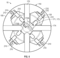
FIG. 6 shows a bottom view of the reamer head ofFIG. 1A including the body and the cutting system, in accordance with at least one example. -
FIG. 7 shows a top view of another illustrative reamer head for minimally invasive surgery (MIS) including a body and at least one arcuate element, in accordance with at least one example. -
FIG. 8 is a flow chart illustrating an example method of manufacturing the orthopedic reamer heads described herein, in accordance with at least one example. - As discussed above, orthopedic implants can be secured to bone to replace a joint or a portion of a joint. To implant an orthopedic device, the surgeon can prepare the bone by removing bone material and shaping the bone to receive the implant.
- In some hip replacement procedures, to remove and shape the bone, the surgeon can ream the bone surface using a driver that is adapted to interface with a reamer head. The reamer head can include cutting elements, that, when rotated by the driver, scrape the bone surface to remove bone and carry the bone away from the implant site.
- Conventional reamer heads are generally cleaned and sterilized after a surgery and reused between patients. Cleaning and sterilizing can be expensive and not all hospitals are able to staff the cleaning facilities all the time. In addition, even after cleaning and sterilizing, the possibility of cross-contamination between patients can still occur.
- The reamer heads and methods of manufacturing described herein reduce the cost to produce the reamer head. Therefore, it can be feasible to provide the reamer head as a disposable, one-time use product. A disposable reamer head eliminates the need to clean and sterilize the reamer head and eliminates a source of cross-contamination between patients.
-
FIGS. 1A ,1B and2-6 show various views of an illustrative example of anorthopedic reamer head 10 and elements thereof. As a general overview and as shown in the perspective view of thereamer head 10, theorthopedic reamer head 10 can include abody 100 and acutting system 200. Together thebody 100 and thecutting system 200 form areamer head 10 having a modular design. - The shape of the
body 100, when rotated, can facilitate reaming an acetabulum to prepare the acetabulum to receive an implant. When thebody 100 is rotated, thereamer head 10 is configured to ream a generally hemispherical shape to approximate the shape of an acetabulum or acetabular implant. - In some examples, the
body 100 can be generally dome-shaped and/or generally hemispherical-shaped. In some examples, a generally hemispherical-shaped dome is not necessarily a perfect or complete hemisphere, but rather thebody 100 has a generally hemispherical form or is provided as a portion of a dome or a portion of a hemisphere. A hemispherical shape can include a generally or substantially hemispherical shape configured to prepare the bone for an acetabular implant, or an implant at another ball and socket joint such as a shoulder joint. - To prepare the bone surface, the
reamer head 10 is rotated at a bone surface using rotational motion provided by a driver (e.g., a universal driver). Thebody 100 of thereamer head 10 can include a driver interface 170 (FIGS. 3 ,5 and6 ) that is configured to be coupled to a driver to receive the rotational motion from the driver. Thedriver interface 170 can be cross-shaped and can extend across thebase 130 of thebody 100. - In some examples, the
body 100, including thedriver interface 170 can be integrally molded as one-piece component including a common polymeric material for theentire body 100 including thedriver interface 170. - In some examples, the
body 100 can be formed of a plurality of polymeric materials and can include a single or multiple components integrally molded to one another. For example, a lower grade polymer can form the majority of thebody 100, while a higher-grade polymer can be used to form the driver interface 170 (FIGS. 3 ,6 and7 ). The use of various polymeric materials can provide the necessary strength at thedriver interface 170, while minimizing the cost of the rest of thebody 100 by using a lower grade and less expensive polymeric material where feasible. - Referring to
FIG. 1A , in a perspective view of thebody 100, thebody 100 can have an outer surface 110 (e.g., outer dome surface) that extends from an apex region 122 (e.g., proximate an apex 120) to abase 130. Arecess 140 can be formed in theouter surface 110 to receive thecutting system 200. Therecess 140 can include at least onearcuate channel 142 extending from a portion of thebody 100 at or near the apex 120 towards thebase 130. At or near the apex 120 can be defined as in theapex region 122, which is shown in further detail inFIG. 5 . - As shown in the example of
FIG. 1A , therecess 140 can include a plurality ofarcuate channels 142 extending away from the apex 120 along a plurality of directions (e.g., 148, 149;FIG. 5 ). The plurality ofdirections base 130. As shown inFIG. 5 , the plurality ofarcuate channels 142 can be arranged in a generally starburst arrangement extending from theapex region 122. - In some examples, the
recess 140 in theouter surface 110 that is configured to accept thecutting system 200 can be formed by multiple recess formations in theouter surface 110 and is not necessarily limited to a single recess, a continuous recess, or a recess of uniform depth. In some examples, thearcuate channels 142 that make up therecess 140 can include apertures (FIG. 5 ) having at least a portion that extends through a thickness of thebody 100, the thickness extending from theouter surface 110 to an inner surface 112 (FIG. 3 ). - The
illustrative body 100 ofFIG. 1A shows the plurality ofarcuate channels 142 as fourarcuate channels 142 arranged in a generally starburst arrangement. However, in some examples, therecess 140 can include any number ofarcuate channels 142, such as one, two, three, four, five, six, seven or eightarcuate channels 142, or more than eightarcuate channels 142. The starburst arrangement shown is merely one example of a starburst. - The
body 100, having a generally dome or hemispherical shape, may not include a perfectlygeometric apex 120, but rather an imaginary apex orapex region 122 proximate the location where the geometric apex would be located if thebody 100 was an exact dome or hemisphere. In some examples, and as shown inFIG. 5 , theapex region 122 can include a circumference around the apex 120 (imaginary apex or an apex axis 124) that extends outward to include a specifiedcircumference 121. In some examples, the specifiedcircumference 121 of theapex region 122 corresponds to thediameter 123 of theapex region 122. In some examples, thediameter 123 of theapex region 122 can be 1.5 inches (3.81 cm) around theapex axis 124 and extending from theouter surface 110 to theinner surface 112 along the apex axis 124 (FIG. 3 ). In a possibly more preferred example, the specifiedcircumference 121 of theapex region 122 can include asmaller diameter 123 of 1.0 inches (2.54 cm) around theapex axis 124. In a possibly most preferred example, the specifiedcircumference 121 of theapex region 122 can include adiameter 123 of 0.5 inches (1.27 cm) around theapex axis 124. - The
body 100 supports thecutting system 200 that facilitates the cutting action of thereamer head 10. As shown in the example ofFIG. 1A , thecutting system 200 can include a plurality ofarcuate elements 210 configured to cut bone.FIG. 4 shows a perspective view of an examplearcuate element 210 of the cutting system without thebody 100. As shown inFIGS. 1A andFIG. 4 together, each of thearcuate elements 210 can extend from afirst end portion 220 proximate the apex 120 to asecond end portion 230 more distal from the apex 120, towards or proximate thebase 130. - As shown in
FIG. 1A , like thearcuate channels 142 of thebody 100, thearcuate elements 210 of thecutting system 200 can also extend outward in a generally starburst arrangement. The generally starburst arrangement can includearcuate elements 210 extending away from the apex 120 (the imaginary apex, apex axis 124), or anywhere in theapex region 122 of thebody 100 towards thebase 130. - Also, like the arrangement of the
arcuate channels 142, thecutting system 200 can include any number ofarcuate elements 210, such as one, two, three, four, five, six, seven or eightarcuate elements 210, or more than eightarcuate elements 210. However, in at least one example, thereamer head 10 can include a singlearcuate element 210 and a singlearcuate channel 142. - In some examples and as shown in the close-up view of
FIG. 1B ,first end portions 220 of at least two of the plurality ofarcuate elements 210 can overlap or be located adjacent to one another. For example, as shown inFIG 1B , at least one of the plurality ofarcuate elements 210 can extend across the apex 120. For example, first end portion 220A of thearcuate element 210A can overlay the apex 120 (e.g., imaginary apex, or apex region 122). Other of the plurality ofarcuate elements first end portions arcuate elements arcuate element 210A. - In at least one example, at least two of the
first end portions apex region 122. - As show in
FIG. 1A , each of the plurality ofarcuate elements 210 can be located in a respective one of the plurality ofarcuate channels 142 formed in thebody 100. Thearcuate elements 210 can be coupled to thebody 100, for example: by retention features that create a snap-fit connection between thearcuate elements 210 and thebody 100; by integrally molding thearcuate elements 210 into thebody 100; or by other attachment methods such as fasteners, adhesives or heat-staking. Thecutting system 200 can be formed from stamped metal, such as surgical steel or another biocompatible material having sufficient strength to be retained by thebody 100 and to cut bone. - As shown in
FIGS. 1A ,3 and4 , at least one of thearcuate elements 210 can include the cuttingelements 250 configured to remove bone. The cuttingelements 250 can extend outward from the respectivearcuate channel 142 beyond theouter surface 110. For example, the cuttingelements 250 can extend outward radially from the generally hemispheric shapedbody 100. Because the cuttingelements 250 extend beyond theouter surface 110, when thereamer head 10 is placed at an implant site of the bone, such as an acetabulum, the cuttingelements 250 can come into contact with the bone. - As shown in
FIGS. 1A ,1B and4 , eacharcuate element 210 can include a plurality of cuttingelements 250. However, in some examples, one or more of thearcuate elements 210 can include asingle cutting element 250, or differentarcuate elements 210 can include different numbers, size, shape or arrangement of the cuttingelements 250. - Although the number of arcuate elements in
FIG. 1A is shown as four. In some examples, thearcuate elements 210 can be provided in multiples of four, such as four, eight or twelvearcuate elements 210. Having a pluralityarcuate elements 210 in multiples of four can make it possible to tool and fabricate a reamer head more easily, while still being able to interface with conventional drivers that are designed to engage with a standard driver interface (e.g., 170;FIG. 6 ) having a four cross-bar arrangement. The depth of cut, the number of cuttingelements 250 and orientation can be varied within the multiple of four to minimize tooling and fabrication costs. In other examples, different number of cutting elements and orientation can be provided, including a number that is not a multiple of four. - Another feature of the
driver interface 170 can include anarcuate element support 176 as shown inFIGS. 1A and3 . Thearcuate element support 176 can extend away from thedriver interface 170 towards theapex region aperture 126 and can include a support surface(s) 178 configured to support one or morearcuate elements 210. Thearcuate element support 176 can include avertical channel 171 that extends parallel to the apex axis 124 (FIG. 3 ). In some examples thevertical channel 171 can be defined as agap 173 between afirst portion 176A of anarcuate element support 176 and asecond portion 176B of anarcuate element support 176. In some examples thevertical channel 171 can be defined as agap 173 between afirst portion 170A of adriver interface 170 and asecond portion 170B of a driver interface 170 (FIG. 6 ). In some examples the gap may be in a range between 0.1 inches (0.254 cm) and 0.4 inches (1.016 cm). - To facilitate molding of the complex features of the
body 100, including integrally molding thedriver interface 170, thebody 100 can include an apex region aperture 126 (FIGS. 1A ,3 and5 ) extending from theouter surface 110 to theinner surface 172 of thebody 100. Theapex region aperture 126 can allow tooling for molding thearcuate element support 176 and/or driver interface 170 a passageway through thebody 100 along the apex axis 124 (see,mold direction 124A inFIG. 3 ). - Integrally molding the
driver interface 170 can include providing a first mold cavity that forms theapex region aperture 126 and/or theinner surface 172 of the driver interface 17. A second corresponding mold cavity can be supplied from the opposite side of thebody 100 to mold thebase 130 and/or anouter surface 174 of the driver interface 170 (FIGS. 3 and6 ). In some examples, theapex region aperture 126 can be cross-shaped (e.g., generally cross-shaped) corresponding to the shape of thedriver interface 170 to allow egress of the first mold cavity through theapex region aperture 126 following the molding process. - In some examples, the
arcuate elements 210 can be formed into an arcuate shape prior to assembly with thebody 100 as shown inFIG. 4 . However, in some examples, thearcuate element 210 can be planar prior to assembly, and forced into a curved shape by attachment to thebody 100, thus taking on the arcuate shape in the assembly process. Thearcuate elements 210 can be formed from stamped metal, such as surgical steel or can be formed of another biocompatible material. - In some examples, to provide a specific cutting sharpness, the cutting
elements 250 can be sharpened after being stamped. In other examples, the cuttingelements 250 may not be sharpened (e.g., no post processing) after being stamped. To achieve a specified sharpness without post-processing, the cuttingelements 250 can be stamped such that a material blank for thearcuate element 210 is pierced at an angle (e.g., cuttingelements 250 die cut to the shape shown inFIGS. 1B and4 ) to create abreakaway edge 252 that results in a specified sharpness. - In some examples, cutting
elements 250 can take on a variety of other forms including, protruding elements, studs, and abrasive materials. In some examples, the cutting elements can have three-dimensionally formed holes like a cheese grater. - With reference to
FIG. 5 , each of the plurality ofarcuate channels 142 can extend in a different direction. For example, one of thearcuate channels 142 can extend generally along (but not necessarily aligned to) afirst direction 148 from the apex 120 toward thebase 130. Likewise, a second arcuate channel (another of 142) can extend generally along (but not necessarily aligned to) asecond direction 149 from the apex 120 towards another location on thebase 130. The second direction being different than the first direction. - In some examples, instead of providing individual
arcuate elements 210 that extend along the same arc, two or more of thearcuate elements 210 can be incorporated into one longer arcuate element. For example, a single arcuate element that incorporates two of thearcuate elements 210 into one longer arcuate element can extend from proximate one portion of thebase 130, over theapex region 122 and down towards the opposite side of thebase 130. - As shown in the cross-sectional view of
FIG. 3 , a snap-fit connection can be used to secure thearcuate elements 210 to thebody 100. For example, theretention elements 260 can be slid intoretention apertures 160 in thebody 100. Thebody 100 can further includeretention surfaces 162 configured to receive theretention elements 260. The retention surfaces 162 can retain thearcuate elements 210 in thearcuate channels 142. - As shown in
FIG. 3 , the retention surfaces 162 can capture theretention element 260 of thearcuate element 210 to prevent thearcuate element 210 from being removed from thearcuate channel 142. The retention surfaces 162 andretention elements 260 can be any curved, planar or irregularly shaped features that are suitable for providing a secure snap-fit connection. - With reference to
FIG. 5 , thebody 100 can include one or morebone disposal apertures 150 extending through thebody 100 from theouter surface 110 to aninner surface 112 that is opposite the outer surface 110 (FIG. 3 ). The one or morebone disposal apertures 150 can allow bone that has been cut from the bone site to be collected and removed from the bone site. Removing the bone prevents bone or other tissue fragments from interfering with the implant. In addition, the removed bone can be mixed with other materials to fill voids between the bone surface and the implant. In some examples, each of thearcuate channels 142 can include a respectivebone disposal aperture 150. -
FIG. 7 shows a top view of another illustrativeorthopedic reamer head 20.Reamer head 20 shares similarities with the example ofreamer head 10 ofFIGS. 1A ,1B and2-6 , therefore it is understood that features described with respect to the example ofFIGS. 1A ,1B and2-6 can be included inreamer head 20 and vice-versa. In addition, like numerals can represent like elements, and therefore all the features ofreamer head 20 will not be described in full detail. -
Reamer head 20 shows an example of an orthopedic tool having a reduced size over a standard tool.Reamer head 20 is designed to provide the benefits ofreamer head 10 but also be capable of fitting into a smaller incision during minimally invasive surgery (MIS). In some examples, thereamer head 20 is similar to thereamer head 10 except that the dome or hemispherical-shape of thebody 100 is a truncated dome or hemisphere to be able to fit into the smaller MIS incision. For example, thebody 300 includes opposing first and secondtruncated portions -
Reamer head 20 can otherwise include abody 300 that is generally dome shaped and similar to body 100 (except for thetruncated portions 302, 304) and can include thecutting system 200 coupled to thebody 300. Thebody 300 can have the various recesses and apertures extending therethrough as previously described in the examples ofFIGS. 1A ,1B and2-6 . -
FIG. 8 shows a flow chart illustrating an example method of manufacturing 800 thereamer head 10 ofFIGS. 1A ,1B and2-6 . The example method of manufacturing 800 (hereinafter method 800) described herein is merely illustrative in nature. Although aspects of themethod 800 can be used with and will be described with reference to theexample reamer head 10, themethod 800 can also be used with other reamer heads (includingreamer head 20 ofFIG. 7 ) or other orthopedic tools. Themethod 800 is not limited to the steps specified herein. Themethod 800 can include fewer steps or additional method steps other than those described in this disclosure. - Step 810 can include providing, receiving or manufacturing a
body 100. Thebody 100 can have a generally dome shape including anouter surface 110 extending from anapex region 120 to abase 130. Theouter surface 110 can include arecess 140 extending along a direction from the apex region 122 (e.g., proximate the apex or an imaginary apex 120) towards thebase 130. Therecess 140 can include at least onearcuate channel 142. In some examples, therecess 140 is a plurality of recesses that together form the at least onearcuate channel 142. - In some examples, step 810 can include integrally molding a driver interface with the body. Integrally molding a
driver interface 170 with thebody 100 can include providing, receiving or manufacturing a first mold cavity that forms anapex region aperture 126 proximate the apex 120 orapex region 122 of thebody 100. - Step 820 can include providing, receiving or manufacturing a
cutting system 200 including anarcuate element 210 extending from a first end portion to a second end portion, thearcuate element 210 including a cutting element for removing the bone. In some examples thecutting system 200 can include a one-piece design. - Step 830 can include inserting at least a portion of the
arcuate element 210 into anarcuate channel 142 such that at least a portion of thearcuate element 210 extends outward from thearcuate channel 142 beyond theouter surface 110 of thebody 100. - Step 830 can further include engaging a
retention element 260 of thearcuate element 210 with aretention surface 162 on thebody 100 such that thearcuate element 210 is retained by thebody 100 with at least a portion of the cuttingelement 250 remaining extended outward beyond theouter surface 110. - In some examples the inserting
step 830 can include inserting a plurality of thearcuate element 210 into a plurality of thearcuate channel 142. In some examples, inserting the plurality ofarcuate elements 210 into the plurality ofarcuate channels 142 can include repeatingstep 830 until the plurality ofarcuate elements 210 are arranged in a starburst formation along theouter surface 110. The starburst formation extending away from the apex 120 (or the imaginary apex), or theapex region 122 of thebody 100 towards thebase 130. - As the
arcuate elements 210 are inserted into thearcuate channels 142, step 830 can include placingfirst end portions arcuate elements FIG. 1B . In some examples, at least one of the plurality ofarcuate elements 210 can extend across the apex 120. For example, each of the plurality ofarcuate elements 210 can be inserted into one of the plurality ofarcuate channels 142, and when at least one of the arcuate elements (e.g., 210A;FIG. 1B ) is fully seated in thearcuate channel 142, the first end portion 220A of thearcuate element 210A can overlay the apex 120 (e.g., proximate, near, on, over the apex 120, imaginary apex, or apex region 122). As a second or subsequent arcuate elements (e.g., 210B, 210C, 210D;FIG. 1B ) are inserted and seated, thefirst end portions 220 of thearcuate elements arcuate element 210A. In some examples, step 830 can include overlapping at least two of the plurality ofarcuate elements 210 proximate anapex region 122. - The
method 800 provides reamer heads, including but not limited toreamer head 10, having a modular design that can be made cost effective enough for disposable applications, without sacrificing the performance provided in a re-usable reamer head design. - The above detailed description includes references to the accompanying drawings, which form a part of the detailed description. The drawings show, by way of illustration, specific examples in which the invention can be practiced. These examples are also referred to herein as "examples." Such examples can include elements in addition to those shown or described. However, the present inventors also contemplate examples in which only those elements shown or described are provided. Moreover, the present inventors also contemplate examples using any combination or permutation of those elements shown or described (or one or more aspects thereof), either with respect to a particular example (or one or more aspects thereof), or with respect to other examples (or one or more aspects thereof) shown or described herein.
- In this document, the terms "a" or "an" are used, as is common in patent documents, to include one or more than one, independent of any other instances or usages of "at least one" or "one or more." In this document, the term "or" is used to refer to a nonexclusive or, such that "A or B" includes "A but not B," "B but not A," and "A and B," unless otherwise indicated. In this document, the terms "including" and "in which" are used as the plain-English equivalents of the respective terms "comprising" and "wherein." Also, in the following claims, the terms "including" and "comprising" are open-ended, that is, a system, device, article, composition, formulation, or process that includes elements in addition to those listed after such a term in a claim are still deemed to fall within the scope of that claim. Moreover, in the following claims, the terms "first," "second," and "third," etc. are used merely as labels, and are not intended to impose numerical requirements on their objects.
- The above description is intended to be illustrative, and not restrictive. For example, the above-described examples (or one or more aspects thereof) may be used in combination with each other. Other examples can be used, such as by one of ordinary skill in the art upon reviewing the above description. The Abstract is provided to allow the reader to quickly ascertain the nature of the technical disclosure. It is submitted with the understanding that it will not be used to interpret or limit the scope or meaning of the claims. Also, in the above Detailed Description, various features may be grouped together to streamline the disclosure. This should not be interpreted as intending that an unclaimed disclosed feature is essential to any claim. Rather, inventive subject matter may lie in less than all features of a particular disclosed example. The scope of the invention should be determined with reference to the appended claims, along with the full scope to which such claims are entitled.
Claims (15)
- An orthopedic reamer head (10) for preparing a bone to receive an implant, the orthopedic reamer head (10) comprising:a body (100) having a generally dome shape and an outer surface (110) extending from an apex region (122) to a base (130), the outer surface having (110) a recess (140) including an arcuate channel (142), the arcuate channel (142) extending along a direction from proximate the apex region (122) towards the base (130); anda cutting system (200) having an arcuate element (210), the arcuate element (210) including a cutting element (250) for removing bone and a retention element (260) extending from a side of the arcuate element (210) opposite of the cutting element (250), whereinat least a portion of the arcuate element (210) is located in the arcuate channel (142),at least a portion of the cutting element (250) extends out of the arcuate channel (142) beyond the outer surface (110),the arcuate element (210) extends from a first end portion (220) proximate the apex region to a second end portion (230) proximate the base (130) and characterised in thatthe retention element (260) is at least partially received within a retention aperture (160) in the body (100) and forms a snap-fit connection therewith.
- The orthopedic reamer head of claim 1, wherein the arcuate element (210) extends across an apex (120) of the body (100).
- The orthopedic reamer head of claim 1 or claim 2, wherein the recess (140) includes a plurality of the arcuate channel (142), and wherein the cutting system (200) comprises a plurality of the arcuate element (210), and wherein each of the plurality of arcuate elements (210) are located in one of the plurality of arcuate channels (142).
- The orthopedic reamer head (10) of claim 3, wherein each of the plurality of arcuate elements (210) extend away from the apex region (121) such that the cutting system (200) is arranged in a starburst formation.
- The orthopedic reamer head (10) of any of claims 1-4, wherein the body (100) has a thickness extending from the outer surface (110) to an inner surface (112) opposite the outer surface (110), and wherein the apex region (122) comprises an apex region aperture (126) extending from the outer surface (110) to the inner surface (112).
- The orthopedic reamer head (10) of any of claims 1-5, further comprising a bone disposal aperture (150) extending through the body (100) from the outer surface (110) to an inner surface (112) opposite the outer surface (110).
- The orthopedic reamer head (10) of any of claims 1-6, wherein the body (100) is generally hemispherical-shaped.
- The orthopedic reamer head (10) of claim 1 or claim 2, wherein:the body (100) includes a generally hemispherical-dome shape , the outer dome surface (110) having a recess (140) including a plurality of arcuate channels (142), the plurality of arcuate channels (142) extending from the apex region (122) towards the base (130), the plurality of arcuate channels (142) arranged in a starburst arrangement;the cutting system (200) has a plurality of arcuate elements (210) extending outward in a starburst arrangement from the apex region (122) to second end portions (230) towards the base (130), wherein each of the plurality of arcuate elements (210) is located in one of the plurality of arcuate channels (142); and wherein at least one of the plurality of arcuate elements (210) includes a cutting element (250) for removing the bone.
- The orthopedic reamer head (10) of claim 8, further comprising a driver interface (170) extending across the base (130) of the body, the driver interface (170) including an arcuate element support (176) extending away from the driver interface towards the apex region (122), wherein the arcuate element support (176) includes a support surface (178) configured to support at least one of the plurality of arcuate elements (210).
- The orthopedic reamer head (10) of any of claims 8-9, wherein the apex region (122) includes an apex axis (124) and extends outward along an apex axis to include a circumference around the apex axis (124) having a diameter of 1.5 inches (3.81 cm).
- A method of manufacturing an orthopedic reamer head (10) for preparing a bone, the method comprising:providing, receiving or manufacturing a body (100) having a generally dome shape including an outer dome surface (110) extending from an apex region (122) to a base (130), the outer dome surface (110) having a recess (140) extending along a direction from the apex region (122) to the base (130), the recess including an arcuate channel (142);providing, receiving or manufacturing a cutting system (200) including an arcuate element (210), the arcuate element including a cutting element (250) for removing the bone and a retention element (260) extending from a side of the arcuate element (210) opposite of the cutting element (250); andinserting at least a portion of the arcuate element (210) into the arcuate channel (142), the arcuate element (210) extending from a first end portion (220) proximate the apex region to a second end portion (230) proximate the base (130), wherein at least a portion of the arcuate element (210) extends outward from the arcuate channel (142) beyond the outer dome surface (110) , and characterised in that the retention element (260) is at least partially received within a retention aperture (160) in the body (100) and forms a snap-fit connection therewith.
- The method of claim 11, further comprising engaging the arcuate element (210) with a retention surface (162) on the body (100) such that the arcuate element (210) is retained by the body 100) with at least a portion of the cutting element (250) remaining extended outward beyond the outer dome surface (110).
- The method of any of claims 11-12, wherein the inserting the at least a portion of the arcuate element (210) into the arcuate channel (142) includes inserting a plurality of arcuate elements (210) into a plurality of arcuate channels (142), wherein the plurality of arcuate channels (142) are arranged in a generally starburst formation along the outer dome surface (110) extending away from the apex region (122) of the body towards the base (130).
- The method of any of claim 11-13, further comprising integrally molding a driver interface (170) with the body (100), wherein integrally molding a driver interface (170) includes providing, receiving or manufacturing a first mold cavity that forms an apex region aperture (126) proximate the apex region (122) of the body (100).
- The method of any of claims 11-14, wherein the arcuate element extends across an apex (120) of the body (100).
Applications Claiming Priority (2)
| Application Number | Priority Date | Filing Date | Title |
|---|---|---|---|
| US201862772736P | 2018-11-29 | 2018-11-29 | |
| PCT/US2019/063703 WO2020113072A1 (en) | 2018-11-29 | 2019-11-27 | Disposable acetabular modular reamer and method of manufaturing |
Publications (2)
| Publication Number | Publication Date |
|---|---|
| EP3886735A1 EP3886735A1 (en) | 2021-10-06 |
| EP3886735B1 true EP3886735B1 (en) | 2025-07-02 |
Family
ID=68966063
Family Applications (1)
| Application Number | Title | Priority Date | Filing Date |
|---|---|---|---|
| EP19824127.5A Active EP3886735B1 (en) | 2018-11-29 | 2019-11-27 | Disposable acetabular modular reamer and method of manufaturing |
Country Status (3)
| Country | Link |
|---|---|
| US (1) | US11540844B2 (en) |
| EP (1) | EP3886735B1 (en) |
| WO (1) | WO2020113072A1 (en) |
Families Citing this family (1)
| Publication number | Priority date | Publication date | Assignee | Title |
|---|---|---|---|---|
| US11540844B2 (en) | 2018-11-29 | 2023-01-03 | Zimmer, Inc. | Disposable acetabular modular reamer and methods |
Family Cites Families (5)
| Publication number | Priority date | Publication date | Assignee | Title |
|---|---|---|---|---|
| EP2359755B1 (en) * | 2010-02-12 | 2014-01-15 | Greatbatch Ltd. | Disposable reamer |
| US10092304B2 (en) | 2014-09-30 | 2018-10-09 | Depuy Ireland Unlimited Company | Orthopaedic surgical instrument assembly for reaming a patient's acetabulum |
| EP3127494B1 (en) | 2015-08-07 | 2018-06-27 | Greatbatch Ltd. | Bi-directional reamer assembly |
| GB2544095A (en) * | 2015-11-06 | 2017-05-10 | Embody Orthopaedic Ltd | Rotary cutter for preparing the acetabular socket for a hip implant |
| US11540844B2 (en) | 2018-11-29 | 2023-01-03 | Zimmer, Inc. | Disposable acetabular modular reamer and methods |
-
2019
- 2019-11-27 US US16/698,364 patent/US11540844B2/en active Active
- 2019-11-27 EP EP19824127.5A patent/EP3886735B1/en active Active
- 2019-11-27 WO PCT/US2019/063703 patent/WO2020113072A1/en not_active Ceased
Also Published As
| Publication number | Publication date |
|---|---|
| US20200170653A1 (en) | 2020-06-04 |
| US11540844B2 (en) | 2023-01-03 |
| WO2020113072A1 (en) | 2020-06-04 |
| EP3886735A1 (en) | 2021-10-06 |
Similar Documents
| Publication | Publication Date | Title |
|---|---|---|
| JP7466267B2 (en) | Fusion cage with integrated fixation and insertion features | |
| US9107677B2 (en) | Disposable surgical hemispherical cutter for convex and concave surfaces | |
| US8900251B2 (en) | Radial deployment surgical tool | |
| EP2957245B1 (en) | Disposable cutter acetabular reamer | |
| CA2860795C (en) | Medical reamers and methods of forming the same | |
| US20180206859A1 (en) | Femoral hip stem explant system and methods of using the same | |
| AU2004316340B2 (en) | Intervertebral implant and surgical method for spondylosyndesis of a lumbar vertebral column | |
| US20170181756A1 (en) | Limited use acetabular reamer | |
| JP2013531517A5 (en) | ||
| US9173663B2 (en) | Adapter for a surgical reamer driver | |
| JP2011139918A (en) | Apparatus and method for minimally invasive total joint replacement | |
| US11478257B2 (en) | Tool for cutting bone for surgical use | |
| EP3023063A1 (en) | Orthopaedic reamer connector | |
| US20160100957A1 (en) | Acetabular explant apparatus, system, and method | |
| US10603052B2 (en) | Bone cutter for creating hemispherical cavities | |
| WO2014063197A1 (en) | A surgical instrument | |
| US11540844B2 (en) | Disposable acetabular modular reamer and methods | |
| EP1582155B1 (en) | Acetabular instrument | |
| EP3911279B1 (en) | Sizer, introducer and template device | |
| US10022133B2 (en) | Surgical tool with shroud and alignment feature | |
| HK40053366B (en) | Sizer, introducer and template device | |
| HK40053366A (en) | Sizer, introducer and template device |
Legal Events
| Date | Code | Title | Description |
|---|---|---|---|
| STAA | Information on the status of an ep patent application or granted ep patent |
Free format text: STATUS: UNKNOWN |
|
| STAA | Information on the status of an ep patent application or granted ep patent |
Free format text: STATUS: THE INTERNATIONAL PUBLICATION HAS BEEN MADE |
|
| PUAI | Public reference made under article 153(3) epc to a published international application that has entered the european phase |
Free format text: ORIGINAL CODE: 0009012 |
|
| STAA | Information on the status of an ep patent application or granted ep patent |
Free format text: STATUS: REQUEST FOR EXAMINATION WAS MADE |
|
| 17P | Request for examination filed |
Effective date: 20210629 |
|
| AK | Designated contracting states |
Kind code of ref document: A1 Designated state(s): AL AT BE BG CH CY CZ DE DK EE ES FI FR GB GR HR HU IE IS IT LI LT LU LV MC MK MT NL NO PL PT RO RS SE SI SK SM TR |
|
| DAV | Request for validation of the european patent (deleted) | ||
| DAX | Request for extension of the european patent (deleted) | ||
| STAA | Information on the status of an ep patent application or granted ep patent |
Free format text: STATUS: EXAMINATION IS IN PROGRESS |
|
| 17Q | First examination report despatched |
Effective date: 20230322 |
|
| GRAP | Despatch of communication of intention to grant a patent |
Free format text: ORIGINAL CODE: EPIDOSNIGR1 |
|
| STAA | Information on the status of an ep patent application or granted ep patent |
Free format text: STATUS: GRANT OF PATENT IS INTENDED |
|
| INTG | Intention to grant announced |
Effective date: 20250206 |
|
| GRAS | Grant fee paid |
Free format text: ORIGINAL CODE: EPIDOSNIGR3 |
|
| GRAA | (expected) grant |
Free format text: ORIGINAL CODE: 0009210 |
|
| STAA | Information on the status of an ep patent application or granted ep patent |
Free format text: STATUS: THE PATENT HAS BEEN GRANTED |
|
| AK | Designated contracting states |
Kind code of ref document: B1 Designated state(s): AL AT BE BG CH CY CZ DE DK EE ES FI FR GB GR HR HU IE IS IT LI LT LU LV MC MK MT NL NO PL PT RO RS SE SI SK SM TR |
|
| REG | Reference to a national code |
Ref country code: GB Ref legal event code: FG4D |
|
| P01 | Opt-out of the competence of the unified patent court (upc) registered |
Free format text: CASE NUMBER: APP_25682/2025 Effective date: 20250528 |
|
| REG | Reference to a national code |
Ref country code: CH Ref legal event code: EP |
|
| REG | Reference to a national code |
Ref country code: DE Ref legal event code: R096 Ref document number: 602019072034 Country of ref document: DE |
|
| REG | Reference to a national code |
Ref country code: IE Ref legal event code: FG4D |
|
| REG | Reference to a national code |
Ref country code: NL Ref legal event code: MP Effective date: 20250702 |
|
| PG25 | Lapsed in a contracting state [announced via postgrant information from national office to epo] |
Ref country code: PT Free format text: LAPSE BECAUSE OF FAILURE TO SUBMIT A TRANSLATION OF THE DESCRIPTION OR TO PAY THE FEE WITHIN THE PRESCRIBED TIME-LIMIT Effective date: 20251103 |
|
| PG25 | Lapsed in a contracting state [announced via postgrant information from national office to epo] |
Ref country code: NL Free format text: LAPSE BECAUSE OF FAILURE TO SUBMIT A TRANSLATION OF THE DESCRIPTION OR TO PAY THE FEE WITHIN THE PRESCRIBED TIME-LIMIT Effective date: 20250702 |
|
| REG | Reference to a national code |
Ref country code: AT Ref legal event code: MK05 Ref document number: 1808344 Country of ref document: AT Kind code of ref document: T Effective date: 20250702 |
|
| PG25 | Lapsed in a contracting state [announced via postgrant information from national office to epo] |
Ref country code: IS Free format text: LAPSE BECAUSE OF FAILURE TO SUBMIT A TRANSLATION OF THE DESCRIPTION OR TO PAY THE FEE WITHIN THE PRESCRIBED TIME-LIMIT Effective date: 20251102 |
|
| PGFP | Annual fee paid to national office [announced via postgrant information from national office to epo] |
Ref country code: DE Payment date: 20251021 Year of fee payment: 7 |
|
| PGFP | Annual fee paid to national office [announced via postgrant information from national office to epo] |
Ref country code: GB Payment date: 20251114 Year of fee payment: 7 |
|
| PG25 | Lapsed in a contracting state [announced via postgrant information from national office to epo] |
Ref country code: NO Free format text: LAPSE BECAUSE OF FAILURE TO SUBMIT A TRANSLATION OF THE DESCRIPTION OR TO PAY THE FEE WITHIN THE PRESCRIBED TIME-LIMIT Effective date: 20251002 |
|
| REG | Reference to a national code |
Ref country code: LT Ref legal event code: MG9D |
|
| PG25 | Lapsed in a contracting state [announced via postgrant information from national office to epo] |
Ref country code: AT Free format text: LAPSE BECAUSE OF FAILURE TO SUBMIT A TRANSLATION OF THE DESCRIPTION OR TO PAY THE FEE WITHIN THE PRESCRIBED TIME-LIMIT Effective date: 20250702 |
|
| PG25 | Lapsed in a contracting state [announced via postgrant information from national office to epo] |
Ref country code: FI Free format text: LAPSE BECAUSE OF FAILURE TO SUBMIT A TRANSLATION OF THE DESCRIPTION OR TO PAY THE FEE WITHIN THE PRESCRIBED TIME-LIMIT Effective date: 20250702 |
|
| PG25 | Lapsed in a contracting state [announced via postgrant information from national office to epo] |
Ref country code: HR Free format text: LAPSE BECAUSE OF FAILURE TO SUBMIT A TRANSLATION OF THE DESCRIPTION OR TO PAY THE FEE WITHIN THE PRESCRIBED TIME-LIMIT Effective date: 20250702 |
|
| PG25 | Lapsed in a contracting state [announced via postgrant information from national office to epo] |
Ref country code: GR Free format text: LAPSE BECAUSE OF FAILURE TO SUBMIT A TRANSLATION OF THE DESCRIPTION OR TO PAY THE FEE WITHIN THE PRESCRIBED TIME-LIMIT Effective date: 20251003 |
|
| PG25 | Lapsed in a contracting state [announced via postgrant information from national office to epo] |
Ref country code: SE Free format text: LAPSE BECAUSE OF FAILURE TO SUBMIT A TRANSLATION OF THE DESCRIPTION OR TO PAY THE FEE WITHIN THE PRESCRIBED TIME-LIMIT Effective date: 20250702 Ref country code: CZ Free format text: LAPSE BECAUSE OF FAILURE TO SUBMIT A TRANSLATION OF THE DESCRIPTION OR TO PAY THE FEE WITHIN THE PRESCRIBED TIME-LIMIT Effective date: 20250702 |
|
| PG25 | Lapsed in a contracting state [announced via postgrant information from national office to epo] |
Ref country code: LV Free format text: LAPSE BECAUSE OF FAILURE TO SUBMIT A TRANSLATION OF THE DESCRIPTION OR TO PAY THE FEE WITHIN THE PRESCRIBED TIME-LIMIT Effective date: 20250702 |
|
| PG25 | Lapsed in a contracting state [announced via postgrant information from national office to epo] |
Ref country code: PL Free format text: LAPSE BECAUSE OF FAILURE TO SUBMIT A TRANSLATION OF THE DESCRIPTION OR TO PAY THE FEE WITHIN THE PRESCRIBED TIME-LIMIT Effective date: 20250702 Ref country code: BG Free format text: LAPSE BECAUSE OF FAILURE TO SUBMIT A TRANSLATION OF THE DESCRIPTION OR TO PAY THE FEE WITHIN THE PRESCRIBED TIME-LIMIT Effective date: 20250702 |
|
| PG25 | Lapsed in a contracting state [announced via postgrant information from national office to epo] |
Ref country code: RS Free format text: LAPSE BECAUSE OF FAILURE TO SUBMIT A TRANSLATION OF THE DESCRIPTION OR TO PAY THE FEE WITHIN THE PRESCRIBED TIME-LIMIT Effective date: 20251002 |
|
| PG25 | Lapsed in a contracting state [announced via postgrant information from national office to epo] |
Ref country code: ES Free format text: LAPSE BECAUSE OF FAILURE TO SUBMIT A TRANSLATION OF THE DESCRIPTION OR TO PAY THE FEE WITHIN THE PRESCRIBED TIME-LIMIT Effective date: 20250702 |
|
| PG25 | Lapsed in a contracting state [announced via postgrant information from national office to epo] |
Ref country code: RO Free format text: LAPSE BECAUSE OF FAILURE TO SUBMIT A TRANSLATION OF THE DESCRIPTION OR TO PAY THE FEE WITHIN THE PRESCRIBED TIME-LIMIT Effective date: 20250702 |
|
| PG25 | Lapsed in a contracting state [announced via postgrant information from national office to epo] |
Ref country code: SM Free format text: LAPSE BECAUSE OF FAILURE TO SUBMIT A TRANSLATION OF THE DESCRIPTION OR TO PAY THE FEE WITHIN THE PRESCRIBED TIME-LIMIT Effective date: 20250702 |
|
| PG25 | Lapsed in a contracting state [announced via postgrant information from national office to epo] |
Ref country code: DK Free format text: LAPSE BECAUSE OF FAILURE TO SUBMIT A TRANSLATION OF THE DESCRIPTION OR TO PAY THE FEE WITHIN THE PRESCRIBED TIME-LIMIT Effective date: 20250702 |
|
| PG25 | Lapsed in a contracting state [announced via postgrant information from national office to epo] |
Ref country code: IT Free format text: LAPSE BECAUSE OF FAILURE TO SUBMIT A TRANSLATION OF THE DESCRIPTION OR TO PAY THE FEE WITHIN THE PRESCRIBED TIME-LIMIT Effective date: 20250702 |
|
| PG25 | Lapsed in a contracting state [announced via postgrant information from national office to epo] |
Ref country code: EE Free format text: LAPSE BECAUSE OF FAILURE TO SUBMIT A TRANSLATION OF THE DESCRIPTION OR TO PAY THE FEE WITHIN THE PRESCRIBED TIME-LIMIT Effective date: 20250702 Ref country code: SK Free format text: LAPSE BECAUSE OF FAILURE TO SUBMIT A TRANSLATION OF THE DESCRIPTION OR TO PAY THE FEE WITHIN THE PRESCRIBED TIME-LIMIT Effective date: 20250702 |
|
| PLBE | No opposition filed within time limit |
Free format text: ORIGINAL CODE: 0009261 |
|
| STAA | Information on the status of an ep patent application or granted ep patent |
Free format text: STATUS: NO OPPOSITION FILED WITHIN TIME LIMIT |