EP3886408B1 - Display apparatus and control method thereof - Google Patents
Display apparatus and control method thereof Download PDFInfo
- Publication number
- EP3886408B1 EP3886408B1 EP20202096.2A EP20202096A EP3886408B1 EP 3886408 B1 EP3886408 B1 EP 3886408B1 EP 20202096 A EP20202096 A EP 20202096A EP 3886408 B1 EP3886408 B1 EP 3886408B1
- Authority
- EP
- European Patent Office
- Prior art keywords
- display
- camera
- processor
- photographing
- image
- Prior art date
- Legal status (The legal status is an assumption and is not a legal conclusion. Google has not performed a legal analysis and makes no representation as to the accuracy of the status listed.)
- Active
Links
Images








Classifications
-
- G—PHYSICS
- G06—COMPUTING OR CALCULATING; COUNTING
- G06F—ELECTRIC DIGITAL DATA PROCESSING
- G06F3/00—Input arrangements for transferring data to be processed into a form capable of being handled by the computer; Output arrangements for transferring data from processing unit to output unit, e.g. interface arrangements
- G06F3/01—Input arrangements or combined input and output arrangements for interaction between user and computer
- G06F3/03—Arrangements for converting the position or the displacement of a member into a coded form
- G06F3/041—Digitisers, e.g. for touch screens or touch pads, characterised by the transducing means
- G06F3/042—Digitisers, e.g. for touch screens or touch pads, characterised by the transducing means by opto-electronic means
- G06F3/0425—Digitisers, e.g. for touch screens or touch pads, characterised by the transducing means by opto-electronic means using a single imaging device like a video camera for tracking the absolute position of a single or a plurality of objects with respect to an imaged reference surface, e.g. video camera imaging a display or a projection screen, a table or a wall surface, on which a computer generated image is displayed or projected
-
- H—ELECTRICITY
- H04—ELECTRIC COMMUNICATION TECHNIQUE
- H04N—PICTORIAL COMMUNICATION, e.g. TELEVISION
- H04N5/00—Details of television systems
- H04N5/64—Constructional details of receivers, e.g. cabinets or dust covers
-
- H—ELECTRICITY
- H04—ELECTRIC COMMUNICATION TECHNIQUE
- H04N—PICTORIAL COMMUNICATION, e.g. TELEVISION
- H04N23/00—Cameras or camera modules comprising electronic image sensors; Control thereof
- H04N23/60—Control of cameras or camera modules
- H04N23/61—Control of cameras or camera modules based on recognised objects
-
- H—ELECTRICITY
- H04—ELECTRIC COMMUNICATION TECHNIQUE
- H04M—TELEPHONIC COMMUNICATION
- H04M1/00—Substation equipment, e.g. for use by subscribers
- H04M1/02—Constructional features of telephone sets
- H04M1/0202—Portable telephone sets, e.g. cordless phones, mobile phones or bar type handsets
- H04M1/0206—Portable telephones comprising a plurality of mechanically joined movable body parts, e.g. hinged housings
- H04M1/0208—Portable telephones comprising a plurality of mechanically joined movable body parts, e.g. hinged housings characterized by the relative motions of the body parts
- H04M1/0225—Rotatable telephones, i.e. the body parts pivoting to an open position around an axis perpendicular to the plane they define in closed position
-
- F—MECHANICAL ENGINEERING; LIGHTING; HEATING; WEAPONS; BLASTING
- F16—ENGINEERING ELEMENTS AND UNITS; GENERAL MEASURES FOR PRODUCING AND MAINTAINING EFFECTIVE FUNCTIONING OF MACHINES OR INSTALLATIONS; THERMAL INSULATION IN GENERAL
- F16M—FRAMES, CASINGS OR BEDS OF ENGINES, MACHINES OR APPARATUS, NOT SPECIFIC TO ENGINES, MACHINES OR APPARATUS PROVIDED FOR ELSEWHERE; STANDS; SUPPORTS
- F16M11/00—Stands or trestles as supports for apparatus or articles placed thereon ; Stands for scientific apparatus such as gravitational force meters
- F16M11/02—Heads
- F16M11/04—Means for attachment of apparatus; Means allowing adjustment of the apparatus relatively to the stand
- F16M11/06—Means for attachment of apparatus; Means allowing adjustment of the apparatus relatively to the stand allowing pivoting
- F16M11/10—Means for attachment of apparatus; Means allowing adjustment of the apparatus relatively to the stand allowing pivoting around a horizontal axis
- F16M11/105—Means for attachment of apparatus; Means allowing adjustment of the apparatus relatively to the stand allowing pivoting around a horizontal axis the horizontal axis being the roll axis, e.g. for creating a landscape-portrait rotation
-
- G—PHYSICS
- G06—COMPUTING OR CALCULATING; COUNTING
- G06F—ELECTRIC DIGITAL DATA PROCESSING
- G06F1/00—Details not covered by groups G06F3/00 - G06F13/00 and G06F21/00
- G06F1/16—Constructional details or arrangements
- G06F1/1601—Constructional details related to the housing of computer displays, e.g. of CRT monitors, of flat displays
- G06F1/1605—Multimedia displays, e.g. with integrated or attached speakers, cameras, microphones
-
- G—PHYSICS
- G09—EDUCATION; CRYPTOGRAPHY; DISPLAY; ADVERTISING; SEALS
- G09G—ARRANGEMENTS OR CIRCUITS FOR CONTROL OF INDICATING DEVICES USING STATIC MEANS TO PRESENT VARIABLE INFORMATION
- G09G3/00—Control arrangements or circuits, of interest only in connection with visual indicators other than cathode-ray tubes
- G09G3/20—Control arrangements or circuits, of interest only in connection with visual indicators other than cathode-ray tubes for presentation of an assembly of a number of characters, e.g. a page, by composing the assembly by combination of individual elements arranged in a matrix no fixed position being assigned to or needed to be assigned to the individual characters or partial characters
-
- H—ELECTRICITY
- H04—ELECTRIC COMMUNICATION TECHNIQUE
- H04M—TELEPHONIC COMMUNICATION
- H04M1/00—Substation equipment, e.g. for use by subscribers
- H04M1/02—Constructional features of telephone sets
- H04M1/0202—Portable telephone sets, e.g. cordless phones, mobile phones or bar type handsets
- H04M1/0206—Portable telephones comprising a plurality of mechanically joined movable body parts, e.g. hinged housings
- H04M1/0241—Portable telephones comprising a plurality of mechanically joined movable body parts, e.g. hinged housings using relative motion of the body parts to change the operational status of the telephone set, e.g. switching on/off, answering incoming call
- H04M1/0243—Portable telephones comprising a plurality of mechanically joined movable body parts, e.g. hinged housings using relative motion of the body parts to change the operational status of the telephone set, e.g. switching on/off, answering incoming call using the relative angle between housings
-
- H—ELECTRICITY
- H04—ELECTRIC COMMUNICATION TECHNIQUE
- H04M—TELEPHONIC COMMUNICATION
- H04M1/00—Substation equipment, e.g. for use by subscribers
- H04M1/02—Constructional features of telephone sets
- H04M1/0202—Portable telephone sets, e.g. cordless phones, mobile phones or bar type handsets
- H04M1/026—Details of the structure or mounting of specific components
- H04M1/0264—Details of the structure or mounting of specific components for a camera module assembly
-
- H—ELECTRICITY
- H04—ELECTRIC COMMUNICATION TECHNIQUE
- H04N—PICTORIAL COMMUNICATION, e.g. TELEVISION
- H04N21/00—Selective content distribution, e.g. interactive television or video on demand [VOD]
- H04N21/40—Client devices specifically adapted for the reception of or interaction with content, e.g. set-top-box [STB]; Operations thereof
- H04N21/41—Structure of client; Structure of client peripherals
- H04N21/422—Input-only peripherals, i.e. input devices connected to specially adapted client devices, e.g. global positioning system [GPS]
- H04N21/4223—Cameras
-
- H—ELECTRICITY
- H04—ELECTRIC COMMUNICATION TECHNIQUE
- H04N—PICTORIAL COMMUNICATION, e.g. TELEVISION
- H04N21/00—Selective content distribution, e.g. interactive television or video on demand [VOD]
- H04N21/40—Client devices specifically adapted for the reception of or interaction with content, e.g. set-top-box [STB]; Operations thereof
- H04N21/43—Processing of content or additional data, e.g. demultiplexing additional data from a digital video stream; Elementary client operations, e.g. monitoring of home network or synchronising decoder's clock; Client middleware
- H04N21/442—Monitoring of processes or resources, e.g. detecting the failure of a recording device, monitoring the downstream bandwidth, the number of times a movie has been viewed, the storage space available from the internal hard disk
- H04N21/44213—Monitoring of end-user related data
-
- H—ELECTRICITY
- H04—ELECTRIC COMMUNICATION TECHNIQUE
- H04N—PICTORIAL COMMUNICATION, e.g. TELEVISION
- H04N23/00—Cameras or camera modules comprising electronic image sensors; Control thereof
- H04N23/45—Cameras or camera modules comprising electronic image sensors; Control thereof for generating image signals from two or more image sensors being of different type or operating in different modes, e.g. with a CMOS sensor for moving images in combination with a charge-coupled device [CCD] for still images
-
- H—ELECTRICITY
- H04—ELECTRIC COMMUNICATION TECHNIQUE
- H04N—PICTORIAL COMMUNICATION, e.g. TELEVISION
- H04N23/00—Cameras or camera modules comprising electronic image sensors; Control thereof
- H04N23/57—Mechanical or electrical details of cameras or camera modules specially adapted for being embedded in other devices
-
- H—ELECTRICITY
- H04—ELECTRIC COMMUNICATION TECHNIQUE
- H04N—PICTORIAL COMMUNICATION, e.g. TELEVISION
- H04N23/00—Cameras or camera modules comprising electronic image sensors; Control thereof
- H04N23/60—Control of cameras or camera modules
-
- H—ELECTRICITY
- H04—ELECTRIC COMMUNICATION TECHNIQUE
- H04N—PICTORIAL COMMUNICATION, e.g. TELEVISION
- H04N23/00—Cameras or camera modules comprising electronic image sensors; Control thereof
- H04N23/60—Control of cameras or camera modules
- H04N23/66—Remote control of cameras or camera parts, e.g. by remote control devices
-
- H—ELECTRICITY
- H04—ELECTRIC COMMUNICATION TECHNIQUE
- H04N—PICTORIAL COMMUNICATION, e.g. TELEVISION
- H04N23/00—Cameras or camera modules comprising electronic image sensors; Control thereof
- H04N23/60—Control of cameras or camera modules
- H04N23/695—Control of camera direction for changing a field of view, e.g. pan, tilt or based on tracking of objects
-
- H—ELECTRICITY
- H04—ELECTRIC COMMUNICATION TECHNIQUE
- H04N—PICTORIAL COMMUNICATION, e.g. TELEVISION
- H04N23/00—Cameras or camera modules comprising electronic image sensors; Control thereof
- H04N23/90—Arrangement of cameras or camera modules, e.g. multiple cameras in TV studios or sports stadiums
-
- H—ELECTRICITY
- H04—ELECTRIC COMMUNICATION TECHNIQUE
- H04N—PICTORIAL COMMUNICATION, e.g. TELEVISION
- H04N5/00—Details of television systems
- H04N5/222—Studio circuitry; Studio devices; Studio equipment
- H04N5/262—Studio circuits, e.g. for mixing, switching-over, change of character of image, other special effects ; Cameras specially adapted for the electronic generation of special effects
- H04N5/2628—Alteration of picture size, shape, position or orientation, e.g. zooming, rotation, rolling, perspective, translation
-
- H—ELECTRICITY
- H04—ELECTRIC COMMUNICATION TECHNIQUE
- H04N—PICTORIAL COMMUNICATION, e.g. TELEVISION
- H04N5/00—Details of television systems
- H04N5/64—Constructional details of receivers, e.g. cabinets or dust covers
- H04N5/655—Construction or mounting of chassis, e.g. for varying the elevation of the tube
-
- G—PHYSICS
- G06—COMPUTING OR CALCULATING; COUNTING
- G06F—ELECTRIC DIGITAL DATA PROCESSING
- G06F1/00—Details not covered by groups G06F3/00 - G06F13/00 and G06F21/00
- G06F1/16—Constructional details or arrangements
- G06F1/1613—Constructional details or arrangements for portable computers
- G06F1/1615—Constructional details or arrangements for portable computers with several enclosures having relative motions, each enclosure supporting at least one I/O or computing function
- G06F1/1622—Constructional details or arrangements for portable computers with several enclosures having relative motions, each enclosure supporting at least one I/O or computing function with enclosures rotating around an axis perpendicular to the plane they define or with ball-joint coupling, e.g. PDA with display enclosure orientation changeable between portrait and landscape by rotation with respect to a coplanar body enclosure
-
- G—PHYSICS
- G06—COMPUTING OR CALCULATING; COUNTING
- G06F—ELECTRIC DIGITAL DATA PROCESSING
- G06F2200/00—Indexing scheme relating to G06F1/04 - G06F1/32
- G06F2200/16—Indexing scheme relating to G06F1/16 - G06F1/18
- G06F2200/161—Indexing scheme relating to constructional details of the monitor
- G06F2200/1614—Image rotation following screen orientation, e.g. switching from landscape to portrait mode
-
- G—PHYSICS
- G06—COMPUTING OR CALCULATING; COUNTING
- G06F—ELECTRIC DIGITAL DATA PROCESSING
- G06F2200/00—Indexing scheme relating to G06F1/04 - G06F1/32
- G06F2200/16—Indexing scheme relating to G06F1/16 - G06F1/18
- G06F2200/163—Indexing scheme relating to constructional details of the computer
- G06F2200/1637—Sensing arrangement for detection of housing movement or orientation, e.g. for controlling scrolling or cursor movement on the display of an handheld computer
-
- G—PHYSICS
- G09—EDUCATION; CRYPTOGRAPHY; DISPLAY; ADVERTISING; SEALS
- G09G—ARRANGEMENTS OR CIRCUITS FOR CONTROL OF INDICATING DEVICES USING STATIC MEANS TO PRESENT VARIABLE INFORMATION
- G09G2340/00—Aspects of display data processing
- G09G2340/04—Changes in size, position or resolution of an image
- G09G2340/0492—Change of orientation of the displayed image, e.g. upside-down, mirrored
-
- H—ELECTRICITY
- H04—ELECTRIC COMMUNICATION TECHNIQUE
- H04M—TELEPHONIC COMMUNICATION
- H04M2250/00—Details of telephonic subscriber devices
- H04M2250/52—Details of telephonic subscriber devices including functional features of a camera
Definitions
- the disclosure relates to a display apparatus and a control method thereof, and more particularly, to a display apparatus which includes a rotatable display and a control method thereof.
- a user may arrange a display in a horizontal or a vertical direction, and be provided with images at various angles at which the user wants to view the images.
- the photographing direction of the camera of the display apparatus may also be changed. For example, as the photographing direction of the camera faces upward, there is a problem that a user located in the front of the display apparatus cannot be photographed correctly by the camera.
- US 2006/274155 discloses a method and terminal for changing the operation mode in a mobile terminal in order to automatically offer an upright display of an image.
- US 2017/111570 discloses a mobile terminal comprising a rotatable display and a plurality of cameras.
- KR 20190017113 discloses an electronic device including first and second cameras.
- a display apparatus that can control photographing direction of a camera according to a direction of a display, and a control method thereof.
- a display apparatus as set out in claim 1.
- a control method of a display apparatus as set out in claim 8.
- the expressions “A or B,” “at least one of A and/or B,” or “one or more of A and/or B” and the like may include all possible combinations of the listed items.
- “A or B,” “at least one of A and B,” or “at least one of A or B” may refer to all of the following cases: (1) including at least one A, (2) including at least one B, or (3) including at least one A and at least one B.
- one element e.g., a first element
- another element e.g., a second element
- the description that one element is "directly coupled” or “directly connected” to another element can be interpreted to mean that still another element (e.g., a third element) does not exist between the one element and the another element.
- a module or “a part” performs at least one function or operation, and maybe implemented as hardware or software, or as a combination of hardware and software. Further, a plurality of “modules” or “parts” may be integrated into at least one module and implemented as at least one processor, except “modules” or “parts” which need to be implemented as specific hardware.
- the expression “configured to” used in the disclosure may be interchangeably used with other expressions such as “suitable for,” “having the capacity to,” “designed to,” “adapted to,” “made to,” and “capable of,” depending on cases.
- the term “configured to” does not necessarily mean that a device is “specifically designed to” in terms of hardware. Instead, under some circumstances, the expression “a device configured to” may mean that the device “is capable of' performing an operation together with another device or component.
- a processor configured to perform A, B, and C may mean a dedicated processor (e.g., an embedded processor) for performing the corresponding operations, or a generic-purpose processor (e.g., a CPU or an application processor) that can perform the corresponding operations by executing one or more software programs stored in a memory device.
- a dedicated processor e.g., an embedded processor
- a generic-purpose processor e.g., a CPU or an application processor
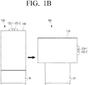
- FIG. 1 is a diagram illustrating a display apparatus according to an embodiment.
- the display apparatus 100 may be implemented as a TV.
- the display apparatus 100 is not limited thereto.
- the display apparatus 100 includes a rotatable display 110.
- the display apparatus 100 may include a stand 10, and the display 110 may be mounted to be rotatable on the stand 10.
- the display apparatus 100 includes a motor for rotating the display 110.
- the display apparatus 100 rotates the display 110 oriented (arranged) in a horizontal direction (or landscape orientation) to be oriented in a vertical direction (or portrait orientation). Also, the display apparatus 100 rotates the display 110 oriented (arranged) in a vertical direction to be oriented a horizontal direction.
- the display apparatus 100 includes a plurality of cameras 120-1, ..., 120-n (here, n is an integer which is greater than or equal to 2).
- the plurality of cameras 120-1, ..., 120-n may be provided on one side of the housing of the display apparatus 100.
- the plurality of cameras 120-1, ..., 120-n may be provided on the vertical side which is relatively short in the housing of the display 110.
- the plurality of cameras 120-1, ..., 120-n may be provided in the bezel area of the display 110, and in this case, the plurality of cameras 120-1, ..., 120-n maybe provided in the bezel area on the vertical side which is relatively short.
- FIG. 1A and FIG. 1B it is illustrated that there are only two cameras 120-1 and 120-2, but this is only an example, and the display apparatus 100 can include two or more cameras.
- the display apparatus 100 includes two cameras 120-1 and 120-2 for photographing images.
- photographing an image means capturing a moving image (video) or one more still images/pictures.
- the plurality of cameras 120-1 and 120-2 are rotated, and the display apparatus 100 includes a motor for rotating each camera 120-1, 120-2, etc.
- each camera 120-1 and 120-2 may respectively rotate in an up-down direction and a left-right direction in the housing wherein the plurality of cameras 120-1 and 120-2 are included, or the housing itself, wherein the plurality of cameras 120-1 and 120-2 are included, may rotate in an up-down direction and a left-right direction.
- the photographing directions of the cameras 120-1 and 120-2 may be changed.
- each camera 120-1 and 120-2 rotates in an upward direction or a downward direction
- the photographing directions of each camera 120-1 and 120-2 may be changed to be more upward or more downward than the directions before rotation.
- the photographing directions of each camera 120-1 and 120-2 may be changed to be more leftward or more rightward than the directions before rotation.
- the display apparatus 100 controls the cameras according to the arrangement state of the display 110, for example, whether the display 110 is arranged in a horizontal direction or a vertical direction, and more detailed explanation will be provided below.
- FIG. 2 is a block diagram illustrating a configuration of a display apparatus according to an embodiment.
- the display apparatus 100 includes a display 110, a plurality of cameras 120-1 and 120-2, and a processor 130.
- the display 110 is mounted on the display apparatus 100 to be rotatable.
- the display 110 may be mounted on the stand 10 so as to allow the display apparatus 100 stand from the ground or the floor, and may be arranged in a horizontal direction or a vertical direction. Also, the display 110 arranged in the horizontal direction is rotated to the vertical direction, and the display 110 arranged in the vertical direction is rotated to the horizontal direction.
- the display apparatus 100 includes a motor for rotating the display 110.
- the display 110 may be implemented as various types of displays such as a liquid crystal display (LCD), light emitting diodes (LEDs), organic light emitting diodes (OLEDs), quantum dot light emitting diodes (QLEDs), etc.
- LCD liquid crystal display
- LEDs light emitting diodes
- OLEDs organic light emitting diodes
- QLEDs quantum dot light emitting diodes
- the plurality of cameras 120-1 and 120-2 may respectively photograph images.
- each camera 120-1 and 120-2 may include an image sensor and a lens, etc.
- the plurality of cameras 120-1 and 120-2 may be arranged at different angles from each other.
- the plurality of cameras 120-1 and 120-2 includes a first camera 120-1 capturing images using a general lens and a second camera 120-2 capturing images using a wide-angle (or an ultra wide-angle) lens having a greater view of angle than a general lens.
- the processor 130 may control the overall operations of the display apparatus 100. Specifically, the processor 130 is electrically connected with the display 110 and the plurality of cameras 120-1 and 120-2, and control these components.
- the processor 130 may include a central processing unit (CPU) or an application processor (AP). Also, the processor 130 may execute one or more software programs stored in the memory according to at least one instruction stored in the memory of the display apparatus 100.
- CPU central processing unit
- AP application processor
- the processor 130 may execute one or more software programs stored in the memory according to at least one instruction stored in the memory of the display apparatus 100.
- the processor 130 may perform photographing by using one of the plurality of cameras 120-1 and 120-2. Then, the processor 130 may display the photographed image on the display 110.
- the processor 130 may perform photographing by using one of the plurality of cameras 120-1 and 120-2.
- the processor 130 may perform photographing by using the first camera 120-1 performing photographing by using a general lens among the plurality of cameras 120-1 and 120-2.
- the processor 130 may rotate the display 110 to the horizontal direction.
- the processor 130 may drive the motor for rotating the display 110, and thereby rotate the display 110 from the vertical direction to the horizontal direction.
- a user command maybe received from a remote controller for controlling the display apparatus 100, or may be input through a button or touch screen provided on the display apparatus 100.
- the processor 130 may rotate the display 110 to the horizontal direction according to a user command, and stop photographing through the camera. That is, the processor 130 may stop photographing by the first camera 120-1 that was performing photographing while the display 110 was arranged in the vertical direction.
- the processor 130 may perform photographing by using the second camera 120-2.
- the second camera 120-2 may be a camera having a greater angle of view than the first camera 120-1. That is, the second camera 120-2 may be a camera performing photographing by using a wide-angle (or an ultra wide-angle) lens having a greater angle of view than a general lens.
- the processor 130 may perform photographing by using the first camera 120-1 among the plurality of cameras 120-1 and 120-2 while the display 110 is arranged in the vertical direction, and if a user command for rotating the display 110 to the horizontal direction is input, the processor 130 may rotate the display 110 to the horizontal direction, stop photographing through the first camera 120-1, and perform photographing through the second camera 120-2.
- the processor 130 may control the display 110 to display an image photographed by the second camera 120-2.
- the image photographed by the second camera 120-2 may be displayed on the display 110.
- the processor 130 may identify an object included in the image photographed through the first camera 120-1 in the image photographed through the second camera 120-2, and display the image photographed by using the second camera 120-2 on the display 110 such that the identified object is displayed in the center area of the display 110 arranged in the horizontal direction.
- the processor 130 photographs an image through the first camera 120-1, and identifies an object in the photographed image.
- the object may include a person's face, etc.
- the processor 130 may rotate the display 110 arranged in the vertical direction to the horizontal direction according to a user command, and as the display 110 rotates, the processor 130 may control the first camera 120-1 to stop photographing, and control the second camera 120-2 to start photographing.
- the processor 130 may identify an object identical to the object identified in the image photographed through the first camera 120-1 in the image photographed through the second camera 120-2. Based on identifying an identical object in the image photographed through the second camera 120-2, the image photographed through the second camera 120-2 may be displayed on the display 110 arranged in the horizontal direction such that the identified object is displayed in the center area of the display 110 arranged in the horizontal direction.
- the processor 130 may detect an area including a person's face in the image photographed through the first camera 120-1 by using a face detection algorithm, etc., and acquire first feature data by analyzing the eyes, nose, mouth, etc. in the detected area.
- the processor 130 may detect an area including a face in the image photographed through the second camera 120-2 and acquire second feature data by analyzing the eyes, nose, mouth, etc. in the detected area. Then, the processor 130 may compare the second feature data with the first feature data acquired in the image photographed through the first camera 120-1, and determine a face area wherein the feature data coincide (or, match) in the image photographed through the second camera 120-2.
- the processor 130 may determine an area including the same face as the face identified in the image photographed through the first camera 120-1 in the image photographed through the second camera 120-2.
- the processor 130 may display the image photographed through the second camera 120-2 on the display 110, such that the area determined in the image photographed through the second camera 120-2 is displayed in the center area of the display 110 arranged in the horizontal direction.
- the processor 130 may rotate the display 110 in the vertical direction, and stop photographing through the second camera 120-2.
- the processor 130 may photograph an image through the first camera 120-1, and display the photographed image on the display 110 arranged in the vertical direction.
- the display apparatus 100 may change the camera performing photographing according to the arrangement state of the display 110.
- the problem of a user having to switch his or her position according to the arrangement of the display is addressed. Specifically, if the display 110 is rotated, the location wherein the camera performs photographing is changed, and in this case, a user has to change his or her location or position as the display 110 is rotated so that his or her appearance can be photographed accurately, and this may cause inconvenience to the user.
- a first image may be photographed through the first camera 120-1 while the display 110 is arranged in the vertical direction, and then, if the display 110 is rotated to the horizontal direction, a second image may be photographed by using the second camera 120-2 having a greater angle of view than the first camera 120-1.
- the processor 130 performs photographing by using a camera having a relatively wider angle of view than a camera used when the direction of the display 110 was arranged in the vertical direction.
- the processor 130 may detect a face detected in the image photographed when the display 110 was in the vertical direction in the image photographed when the display 110 was in the horizontal direction, and display the photographed image on the display 110 arranged in the horizontal direction such that the area including the detected face is displayed in the center portion of the display 110 arranged in the horizontal direction.
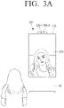
- the processor 130 may photograph an image by using the first camera 120-1 among the plurality of cameras 120-1 and 120-2, and display the photographed image 310 on the display 110.
- the processor 130 may rotate the display 110 to be arranged in the horizontal direction.
- the processor 130 may stop photographing using the first camera 120-1, referring to FIG. 3B , and start photographing an image using the second camera 120-2, and display the photographed image 320 on the display 110.
- the processor 130 may detect a face detected in the image 310 photographed when the display 110 was in the vertical direction in the image photographed when the display 110 was in the horizontal direction, and display the photographed image on the display 110 arranged in the horizontal direction such that the area including the detected face is displayed in the center portion of the display 110 arranged in the horizontal direction.
- the display apparatus 100 may photograph an image through the camera having a greater angle of view than when the display 110 is arranged in the vertical direction. Accordingly, even if photographing starts when the display 110 is in the vertical direction, and the display 110 is rotated in the horizontal direction afterwards, an image that photographed a user correctly can be provided.
- the processor 130 continues to photograph an image by using the first camera 120-1 among the plurality of cameras 120-1 and 120-2.
- the processor 130 detects an area including a person's face in the image photographed through the first camera 120-1, and acquires first feature data by analyzing the eyes, nose, mouth, etc. in the detected area.
- the processor 130 rotates the display 110 such that the display 110 is arranged in the horizontal direction.
- the processor 130 also performs photographing through the first camera 120-1 in case the display 110 is arranged in the horizontal direction.
- the processor 130 does not stop photographing through the first camera 120-1, and performs photographing through the first camera 120-1 even after the display 110 is arranged in the horizontal direction.
- the processor 130 detects an area wherein a person's face is included in the image photographed through the first camera 120-1, and acquires second feature data by analyzing the eyes, nose, mouth, etc. in the detected area.
- the processor 130 performs photographing by using the first camera 120-1.
- the processor 130 stops photographing through the first camera 120-1, and perform photographing by using the second camera 120-2.
- the display apparatus 100 may be configured to stand at a tilted angle ⁇ from the ground as shown in FIG. 4 , for instance.
- the photographing direction 410 of the camera may be directed upward at a specific angle with respect to the horizontal plane.
- the camera may not accurately or correctly photograph a user located in the front of the display apparatus 100 if the camera's angle of view is not wide enough to capture an image of the user.
- the display apparatus 100 may identify the tilting angle by which the display 110 is tilted, and photograph an image by rotating the camera based on the identified tilting angle.
- the display apparatus 100 may further include a sensor.
- the sensor may include at least one of an acceleration sensor, a tilt sensor, a gyro sensor, or a 3-axis magnetic sensor.
- the sensor may collect data and transmit the sensed data to the processor 130.
- the senor may measure the gravitational acceleration of each of the X axis, the Y axis, and the Z axis of the display 110.
- the display 110 mounted on the stand 10 may also be arranged slantingly.
- the gravitational acceleration of at least one axis measured by the sensor may be measured as a value which is not om/sec 2 , and here, the square root of the sum of the squares of the components of the three axes, i.e., the size of the vector sum maybe a specific value (e.g., 9.8m/sec 2 ).
- the sensor may detect the respective acceleration for the X axis, the Y axis, and the Z axis directions on the coordinate system.
- each axis and the gravitational acceleration corresponding thereto may be changed.
- the processor 130 may identify the tilting angle of the display 110 by using the gravitational acceleration transmitted from the sensor.
- the tilting angle may mean an angle by which the display 110 is tilted with respect to the plane perpendicular to the ground or floor on which the display apparatus 100 is made to stand. That is, the tiling angle is an angle between a surface of the display 110 and the plane perpendicular to the ground or floor.
- the processor 130 may calculate the tilting angle of the display 110 (e.g., ⁇ in FIG. 4 ) by using the acceleration measured with respect to each axis component transmitted from the sensor.
- the processor 130 determines the tilting angle of the display 110 by using an acceleration sensor, but this is merely an example, and the processor 130 may determine the tilting angle of the display 110 by using various sensors such as a tilt sensor, a gyro sensor, a magnetic sensor, etc.
- the processor 130 may identify the tilting angle of the display 110 based on sensing data received from the sensor.
- the processor 130 may identify the tilting angle of the display 110 based on sensing data received from the sensor while the display 110 is arranged in the vertical direction.
- the processor 130 may rotate the photographing angle of the camera based on the identified tilting angle.
- the camera may be a first camera 120-1.
- the processor 130 may determine the tilting angle of the display 110 while the display 110 is arranged in the vertical direction, and drive a motor of the first camera 120-1 to rotate the photographing angle of the first camera 120-1 to the lower direction as much as the determined tilting angle.
- the tilting angle of the display 110 is ⁇ 1 ° while the display 110 is arranged in the vertical direction.
- the processor 130 may rotate the photographing angle of the first camera 120-1 to a lower direction as much as ⁇ 1 °.
- the processor 130 may rotate the first camera 120-1 to the lower direction in the housing, or rotate the housing itself in which the first camera 120-1 is included.
- the angle of view 520 of the first camera 120-1 is directed toward the lower side as much as ⁇ 1 ° compared to the angle of view 510 before the first camera 120-1 was rotated.
- the display apparatus 100 can photograph a user in front of the display apparatus 100 more accurately.
- the processor 130 may identify the tilting angle of the display 110 based on sensing data received from the sensor.
- the processor 130 may rotate the photographing angle of the camera based on the identified tilting angle.
- the camera may be a second camera 120-2.
- the processor 130 may determine the tilting angle of the display 110, and drive the motor of the second camera 120-2 to rotate the photographing angle of the second camera 120-2 to the lower direction as much as the tilting angle.
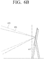
- the tilting angle of the display 110 is ⁇ 2 ° while the display 110 is arranged in the horizontal direction.
- the processor 130 may rotate the photographing angle of the second camera 120-2 to the lower direction as much as ⁇ 2 °.
- the processor 130 may rotate the second camera 120-2 to the lower direction in the housing, or rotate the housing itself in which the second camera 120-2 is included.
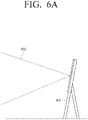
- the angle of view 620 of the second camera 120-2 is lowered as much as ⁇ 2 ° compared to the angle of view 610 before the second camera 120-2 is rotated.
- the display apparatus 100 can photograph a user in the front of the display apparatus 100 more accurately.
- the photographing direction of the camera is changed according to the tilting degree of the display 110 with respect to the ground.
- a user in front of the display apparatus 100 can be photographed more accurately.
- a user may want to change the direction of the display 110 according to the purpose of using the display apparatus 100.
- the user may want to arrange the display 110 in the vertical direction.
- the user may want to arrange the display 110 in the horizontal direction.
- the camera may be used or may not be used.
- the display apparatus 100 may automatically cover the camera by using the camera cover, and thereby protect the privacy of the user.
- the processor 130 may photograph an image by using the first camera 120-1 among the plurality of cameras 120-1 and 120-2.
- the processor 130 may perform photographing by using the first camera 120-1.
- the processor 130 may finish the executed application, and stop photographing by the first camera 120-1.
- the processor 130 may rotate the display 110 to the horizontal direction.
- the processor 130 may drive the camera cover such that the camera cover covers the plurality of cameras 120-1 and 120-2.
- the processor 130 may drive the camera cover to cover the plurality of cameras 120-1 and 120-2.
- the plurality of cameras 120-1 and 120-2 maybe covered.
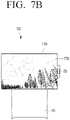
- the processor 130 may photograph the user located in front of the display apparatus 100 by using the first camera 120-1, and display the photographed image 710 on the display 110.
- the processor 130 may finish the application.
- the processor 130 may rotate the display 110 to the horizontal direction.
- the processor 130 may cover the plurality of cameras 120-1 and 120-2 through the camera cover 20.
- the processor 130 may display a broadcasting image 720 on the display 110 arranged in the horizontal direction based on a broadcasting signal received from an external device providing the broadcasting signal.
- the display apparatus 100 covers the camera by using the camera cover when a user does not wish to use the camera.
- the privacy of the user can be protected.
- the method of covering the camera is not limited thereto.
- FIG. 8 is a block diagram illustrating a detailed configuration of a display apparatus according to an embodiment.
- the display apparatus 100 may include a display 110, a plurality of cameras 120 (120-1 and 120-2), a processor 130, a sensor 140, an interface 150, a communication interface 160, a speaker 170, and a memory 180.
- these components may be controlled by the processor 130.
- FIG. 8 The components illustrated in FIG. 8 are merely examples, and depending on embodiments, at least some components can be omitted, or other components can be added.
- the display 110, the plurality of cameras 120, and the processor 130 may perform the functions as described above, and thus overlapping explanation for these components will be omitted.
- the sensor 140 may include at least one of an acceleration sensor, a tilt sensor, a gyro sensor, or a magnetic sensor, and may transmit the sensed data to the processor 130.
- the processor 130 may determine the tilting angle and rotation, etc. of the display 110 by using the sensing data received from the sensor 140.
- a method of measuring the tilting angle and rotation, etc. of the display 110 by using an accelerometer, etc. may be implemented among various methods.
- the interface 150 may be connected with various external apparatuses.
- the interface 150 may be connected with external apparatuses by using various communication methods such as a high definition multimedia interface (HDMI), a universal serial bus (USB), etc.
- HDMI high definition multimedia interface
- USB universal serial bus
- the interface 150 may include an HDMI interface 151 including at least one HDMI port for HDMI communication, and a USB interface 152 including a USB port for USB 2.0 and/or USB 3.0 communication.
- the external apparatuses may include a dongle, a set top box, etc.
- the HDMI interface 151 may include a plurality of HDMI ports, and the dongle and the set top box may respectively be connected through each HDMI port.
- the dongle may be connected with a USB port.
- the processor 130 may display images received from external apparatuses respectively connected with the HDMI interface 151 and the USB interface 152 on the display 110, and output audio received from the external apparatuses through the speaker 170.
- the interface 150 may include a component terminal, an optical terminal, an Ethernet terminal for connection with a local area network (LAN) cable, etc.
- LAN local area network
- the communication interface 160 may perform communication with external apparatuses.
- the communication interface 160 may include a Wi-Fi module 161 for Wi-Fi communication and a Bluetooth module 162 for Bluetooth communication.
- the Wi-Fi module 161 may be connected with an access point, and access the Internet through the access point and perform communication with a server.
- the processor 130 may execute an application stored in the memory 180 according to a user command and access the server providing services through the application, and receive various data such as images and audio from the server through the Wi-Fi module 161.
- the Bluetooth module 162 may perform communication with apparatuses located in vicinity to the display apparatus 100.
- the processor 130 may control the Bluetooth module 162 such that it performs pairing with an apparatus located around the display apparatus 100.
- an electronic apparatus such as a remote controller may be communicatively connected to the electronic apparatus.
- the processor 130 may control the display apparatus 100 according to the received control command.
- the processor 130 may rotate the display 110 arranged in the horizontal direction to the vertical direction, or rotate the display 110 arranged in the vertical direction to the horizontal direction based on the received user command.
- the communicator 160 may include a local area network (LAN) module.
- the LAN module may access the Internet through a LAN cable connected with an Ethernet terminal and perform communication with the server.
- the processor 130 may execute an application stored in the memory 180 according to a user command and access the server providing services through the application, and receive various data such as images and audio from the server through the LAN module.
- the processor 130 may display the received images on the display 110, and output the received audio through the speaker 170.
- the speaker 170 may output audio.
- the processor 130 may output audio received from the dongle, the set top box, the server, etc. through the speaker 170.
- the memory 180 may store various instructions, software programs, applications, and data, etc. related to the display apparatus 100.
- the processor 130 may execute one or more software programs stored in the memory 180 according to at least one instruction stored in the memory 180, and control the overall operations of the display apparatus 100.
- the plurality of cameras 120-1 and 120-2 may be housed inside the display apparatus 100.
- a dongle an apparatus including a plurality of cameras
- the processor 130 may control the plurality of cameras included in the dongle according to the direction in which the display 110 is arranged.
- the dongle may include a plurality of cameras having different angle of views from one another.
- the plurality of cameras may include a first camera performing photographing by using a general lens and a second camera performing photographing by using a wide-angle (or, an ultra wide-angle) lens having a greater angle of view than an angle of view of the general lens.
- the processor 130 may transmit a control command for performing photographing through the first camera among the plurality of cameras of the dongle to the dongle through the interface 150.
- the processor 130 may transmit a control command for performing photographing through the second camera among the plurality of cameras of the dongle to the dongle through the interface 150.
- the processor 130 may transmit a control command for rotating the camera of the dongle to the lower side direction as much as the tilting angle to the dongle through the interface 150, based on the tilting angle of the display 110.
- the processor 130 may transmit a control command for covering the plurality of cameras to the dongle through the interface 150.
- the processor 130 may determine that a user does not want to use the camera.
- the dongle may perform an operation according to a control command received from the display apparatus 100.
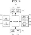
- FIG. 9 is a block diagram illustrating a configuration of a dongle according to an embodiment.
- the dongle 200 may include a plurality of cameras 210, an interface 220, a communication interface 230, a memory 240, and a processor 250.
- Each of the plurality of cameras 210 may photograph images.
- Each camera 210-1, 210-2 may include an image sensor and a lens, etc.
- the number of camera is not limited thereto, but may include more than two cameras.
- the plurality of cameras 210-1, 210-2 may have different angle of views from one another.
- the plurality of cameras 210 may include a first camera 210-1 performing photographing by using a general lens and a second camera 210-2 performing photographing by using a wide-angle (or, an ultra wide-angle) lens having a greater angle of view than that of a general lens.
- the plurality of cameras 210-1, 210-2 may be rotated. That is, the dongle 200 may include a motor, etc. configured to rotate each camera 210-1, 210-2.
- each camera 210-1, 210-2 may respectively rotate in an up-down direction and a left-right direction in the housing of the dongle 200 in which the plurality of cameras 210-1, 210-2 are included,. Also, the dongle 200 may rotate in an up-down direction and a left-right direction while it is connected with the display apparatus 100.
- the interface 220 may be connected with the display apparatus 100.
- the interface 220 may be connected with the display apparatus 100 by using various communication methods such as an HDMI, a USB, etc.
- the interface 220 may include an HDMI interface 221 including an HDMI connector or an HDMI port for HDMI communication, and a USB interface 222 including a USB connector or a USB port for USB 2.0 and/or USB 3.0 communication. Also, the interface 220 may be directly connected with the display apparatus 100, or connected with the display apparatus 100 through a separate cable.
- the communication interface 230 may perform communication with external apparatuses. Specifically, the communication interface 230 may perform communication with external apparatuses by using various communication methods such as mobile communication, Wi-Fi, Bluetooth, etc.
- the communicator 230 may include a mobile communication module 231 for mobile communication such as 3rd Generation (3G), 3rd Generation Partnership Project (3GPP), Long Term Evolution (LTE), 5th Generation (5G), etc., a Wi-Fi module 232 for Wi-Fi communication, and a Bluetooth module 233 for Bluetooth communication.
- a mobile communication module 231 for mobile communication such as 3rd Generation (3G), 3rd Generation Partnership Project (3GPP), Long Term Evolution (LTE), 5th Generation (5G), etc.
- 3GPP 3rd Generation Partnership Project
- LTE Long Term Evolution
- 5G 5th Generation
- the mobile communication module 231 may access the Internet through a mobile communication network and perform communication with the server
- the Wi-Fi module 232 may be connected with the access point, and access the Internet through the access point, and perform communication with the server.
- the Bluetooth module 233 may perform communication with apparatuses located around the dongle 200.
- the memory 240 may store various instructions and software programs, etc. related to the operations of the dongle 200.
- the memory 240 may include a flash memory 241 and a RAM 242.
- the processor 250 may control the overall operations of the dongle 200. That is, the processor 250 may be electrically connected with the plurality of cameras 210-1, 210-2, the interface 220, the communicator 230, and the memory 240, and control these components.
- the processor 250 may include a central processing unit (CPU) or an application processor (AP). Also, the processor 250 may execute one or more software programs stored in the memory 130 according to one or more instructions stored in the memory 240.
- CPU central processing unit
- AP application processor
- the processor 250 may execute one or more software programs stored in the memory 130 according to one or more instructions stored in the memory 240.
- the processor 250 may drive the operating system (OS) stored in the flash memory 241 by using the RAM 242.
- OS may be an OS used in portable apparatuses such as smartphones, tablets, etc. like Android, etc.
- the power applied to the dongle 200 may be provided from the display apparatus 100 connected with the dongle 200 through a USB interface 222.
- the dongle 200 may include a separate battery for supplying power.
- the processor 250 may load an application stored in the flash memory 241 on the RAM 242 and execute the application through the OS.
- the application maybe an application program executed based on the OS of the dongle 200.
- the application may be an application program that can be executed in Android.
- the application may be stored in the memory 240 in the manufacturing stage of the dongle 200, or downloaded from a server providing the application (e.g., play store, etc.) according to a user command and stored in the memory 240.
- the processor 250 may control various operations of the dongle 200 based on a control command received from the display apparatus 100 through the interface 220.
- the processor 250 may perform photographing through the first camera 210-1, and transmit the photographed image to the display apparatus 100 through the interface 220.
- the processor 250 may perform photographing through the second camera 210-2, and transmit the photographed image to the display apparatus 100 through the interface 220.
- the processor 250 may rotate the camera to the lower direction at the received angle, and transmit an image photographed through the rotated camera to the display apparatus 100 through the interface 220.
- the processor 250 may cover the plurality of cameras 210-1, 210-2 with the camera cover.
- the dongle 200 may include a camera cover for covering the plurality of cameras 210-1, 210-2, and accordingly, if a control command for covering the plurality of cameras is received, the processor 250 may drive the camera cover to cover the plurality of cameras 210-1, 210-2.
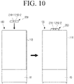
- FIG. 10 is a diagram illustrating a method of connecting a dongle to a display apparatus according to an embodiment.
- the dongle 200 maybe connected with the display apparatus 100.
- the dongle 200 may be connected with the display 110 on one side (e.g., the vertical side) of the display 110 of the display apparatus 100.
- the display apparatus 100 may provide a video call function by using the camera included in the dongle 200.
- a user is performing a video call with another user by using an electronic apparatus (e.g., a mobile phone).
- an electronic apparatus e.g., a mobile phone
- a first electronic apparatus of a user may transmit an image photographed through the camera of the first electronic apparatus and audio received by a microphone of the first electronic apparatus to a second electronic apparatus (e.g., a mobile phone) of another user through the server.
- the first electronic apparatus may then receive an image and audio from the second electronic apparatus of another user through the server.
- the first electronic apparatus of the user may transmit the image and audio received from the second electronic apparatus to the display apparatus 100, and the display apparatus 100 may output the received image and audio respectively through the display and the speaker provided in the display apparatus 100.
- the display apparatus 100 may perform a video call with the second electronic apparatus of another user in place of the first electronic apparatus of the user using the camera included in the dongle 200.
- a user may execute an application for a video call installed on the first electronic apparatus, log in through his or her user account, and perform a video call with a counterpart by using the logged-in user account.
- the first electronic apparatus may perform communication with the display apparatus 100 by using a near field wireless communication (NFC) method.
- NFC near field wireless communication
- the first electronic apparatus and the display apparatus 100 may respectively include a NFC communication module.
- the first electronic apparatus of the user may transmit information on an application for a video call (e.g., identification information such as the name of the application, etc.) and information on the logged-in user account (e.g., the ID and the password, etc.) to the display apparatus 100 by using a near field wireless communication method.
- information on an application for a video call e.g., identification information such as the name of the application, etc.
- information on the logged-in user account e.g., the ID and the password, etc.
- the processor 130 of the display apparatus 100 may receive the information on the application and the information on the user account from the first electronic apparatus.
- the processor 130 may determine an application for a video call among at least one application installed on the display apparatus 100 by using the received information on the application, and execute the determined application. Then, the processor 130 may perform log-in by using the received information on the user account, and receive an image and audio from the second electronic apparatus of the counterpart through the server.
- the processor 130 may output the received image and audio respectively through the display 110 and the speaker 170.
- the processor 130 may transmit a control command for performing photographing through the camera to the dongle 200 through the interface 150.
- the processor 250 may perform photographing by using any one camera among the plurality of cameras 210-1, 210-2 according to the control command received from the display apparatus 100, and transmit the photographed image to the display apparatus 100 through the interface 220.
- the processor 130 may receive audio through the microphone provided on the display apparatus 100, and control the communication interface 160 to transmit the audio received through the microphone and the image received from the dongle 200 to the second electronic apparatus of the counterpart through the server.
- the mobile phone 1100 when a user is performing a video call with a counterpart by using a mobile phone 1100 as shown in FIG. 11A , the mobile phone 1100 maybe in the vicinity of the display apparatus 100 or may come in contact the display apparatus 100 as shown in FIG. 11B .
- the display apparatus 100 may display an image received from the second electronic apparatus of the counterpart of the call on the display 110, and output audio received from the second electronic apparatus of the counterpart of the call through the speaker 170 of the display apparatus 100.
- the display apparatus 100 may transmit audio received through the microphone provided on the display apparatus 100 and an image photographed at the dongle 200 to the second electronic apparatus of the counterpart of the call.
- the display apparatus 100 can provide a seamless video call for a user in place of an electronic apparatus of the user.
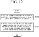
- FIG. 12 is a flowchart illustrating a control method of a display apparatus according to an embodiment.
- the display apparatus may be a rotatable display.
- photographing may be performed by using a camera among a plurality of cameras at operation S1210.
- the display may be rotated to be oriented in the horizontal direction and photographing through the camera may be stopped at operation S1220.
- the plurality of cameras may include a first camera and a second camera having a greater angle of view than that of the first camera.
- photographing may be performed by using the first camera, and at operation S1220, if a user command is input, photographing through the first camera may be stopped and photographing may be performed through the second camera.
- an object included in a first image photographed through the first camera may be identified in a second image photographed through the second camera, and the second image photographed through the second camera maybe displayed on the display such that the identified object is displayed in the center area of the display arranged in the horizontal direction.
- the display may be rotated to the horizontal direction, and the camera cover may be driven such that the camera cover covers the plurality of cameras.
- the tilting angle of the display may be identified based on sensing data received from the sensor, and the photographing angle of the first camera may be rotated based on the identified angle.
- the photographing angle of the camera may be rotated to a lower direction as much as the identified angle.
- the tilted angle of the display may be identified based on sensing data received from the sensor, and the photographing angle of the second camera may be rotated based on the identified angle.
- Various embodiments described above may be implemented as software including instructions stored in machine-readable storage media, which can be read by machines (e.g., computers).
- the machines may refer to apparatuses that call instructions stored in a storage medium, and can operate according to the called instructions, and the apparatuses may include the apparatus according to the aforementioned embodiments.
- the processor may perform a function corresponding to the instruction by itself, or by using other components under its control.
- An instruction may include a code that is generated or executed by a compiler or an interpreter.
- a storage medium that is readable by machines may be provided in the form of a non-transitory storage medium.
- 'non-transitory' may mean that a storage medium is tangible, and does not include signals (e.g., electromagnetic waves), but does not distinguish a case where data is stored in the storage medium semi-permanently and a case where data is stored in the storage medium temporarily.
- 'a non-transitory storage medium' may include a buffer in which data is temporarily stored.
- a computer program product refers to a product, and it can be traded between a seller and a buyer.
- a computer program product can be distributed in the form of a storage medium that is readable by machines (e.g., a compact disc read only memory (CD-ROM)), or may be distributed through an application store (e.g., play store TM) or distributed directly between two user devices (e.g., smartphones), and distributed on-line (e.g., download or upload).
- an application store e.g., play store TM
- two user devices e.g., smartphones
- distributed on-line e.g., download or upload
- at least a portion of a computer program product may be stored in a storage medium such as the server of the manufacturer, the server of the application store, and the memory of the relay server at least temporarily, or may be generated temporarily.
Landscapes
- Engineering & Computer Science (AREA)
- Signal Processing (AREA)
- Multimedia (AREA)
- General Engineering & Computer Science (AREA)
- Theoretical Computer Science (AREA)
- General Physics & Mathematics (AREA)
- Physics & Mathematics (AREA)
- Human Computer Interaction (AREA)
- Computer Hardware Design (AREA)
- Mechanical Engineering (AREA)
- Health & Medical Sciences (AREA)
- Databases & Information Systems (AREA)
- Computer Networks & Wireless Communication (AREA)
- Social Psychology (AREA)
- General Health & Medical Sciences (AREA)
- Controls And Circuits For Display Device (AREA)
- User Interface Of Digital Computer (AREA)
- Studio Devices (AREA)
- Devices For Indicating Variable Information By Combining Individual Elements (AREA)
Description
- The disclosure relates to a display apparatus and a control method thereof, and more particularly, to a display apparatus which includes a rotatable display and a control method thereof.
- Recently, with the development of electronic technologies, various electronic apparatuses are being developed, and in particular, a display apparatus including a rotatable display has been developed.
- With the rotatable display apparatus, a user may arrange a display in a horizontal or a vertical direction, and be provided with images at various angles at which the user wants to view the images.
- However, if a camera is disposed on top of the rotatable display apparatus, the photographing direction of the camera of the display apparatus may also be changed. For example, as the photographing direction of the camera faces upward, there is a problem that a user located in the front of the display apparatus cannot be photographed correctly by the camera.
-
US 2006/274155 discloses a method and terminal for changing the operation mode in a mobile terminal in order to automatically offer an upright display of an image. -
US 2017/111570 discloses a mobile terminal comprising a rotatable display and a plurality of cameras. -
KR 20190017113 - Provided are a display apparatus that can control photographing direction of a camera according to a direction of a display, and a control method thereof.
- Additional aspects will be set forth in part in the description which follows, and in part, will be apparent from the description, or may be learned by practice of the presented embodiments.
- According to an aspect of the invention, there is provided a display apparatus as set out in claim 1. According to another aspect of the invention, there is provided a control method of a display apparatus as set out in claim 8.
- The above and other aspects, features and advantages of certain embodiments will become more apparent from the following description, taken in conjunction with the accompanying drawings, in which:
-
FIG. 1A is a diagram illustrating rotation of a display according to an embodiment; -
FIG. 1B is a diagram illustrating rotation of a display according to an embodiment; -
FIG. 2 is a block diagram illustrating a configuration of a display apparatus according to an embodiment; -
FIG. 3A is a diagram illustrating a method of performing photographing through a camera according to a direction of a display according to an embodiment; -
FIG. 3B is a diagram illustrating a method of performing photographing through a camera according to a direction of a display according to an embodiment; -
FIG. 4 is a diagram illustrating a display apparatus made to stand on a bottom according to an embodiment; -
FIG. 5A is a diagram illustrating a method of changing a photographing direction of a camera in case a display is arranged in a vertical direction according to an embodiment; -
FIG. 5B is a diagram illustrating a method of changing a photographing direction of a camera in case a display is arranged in a vertical direction according to an embodiment; -
FIG. 6A is a diagram illustrating a method of changing a photographing direction of a camera in case a display is arranged in a vertical direction according to an embodiment; -
FIG. 6B is a diagram illustrating a method of changing a photographing direction of a camera in case a display is arranged in a vertical direction according to an embodiment; -
FIG. 7A is a diagram illustrating a method of covering a camera by a camera cover according to an embodiment; -
FIG. 7B is a diagram illustrating a method of covering a camera by a camera cover according to an embodiment; -
FIG. 8 is a block diagram illustrating a detailed configuration of a display apparatus according to an embodiment; -
FIG. 9 is a block diagram illustrating a configuration of a dongle according to an embodiment; -
FIG. 10 is a diagram illustrating a method of connecting a dongle to a display apparatus according to an embodiment; -
FIG. 11A is a diagram illustrating a method of providing a video call function through a camera of a dongle according to an embodiment; -
FIG. 11B is a diagram illustrating a method of providing a video call function through a camera of a dongle according to an embodiment; -
FIG. 11C is a diagram illustrating a method of providing a video call function through a camera of a dongle according to an embodiment; and -
FIG. 12 is a flow chart illustrating a control method of a display apparatus according to an embodiment. - Hereinafter, various embodiments of the disclosure will be described with reference to the accompanying drawings. Also, with respect to the detailed description of the drawings, similar components may be designated by similar reference numerals.
- In the disclosure, terms such as "have," "may have," "include," and "may include" should be construed as denoting that characteristics and elements such as numerical values, functions, operations, and components, and the terms are not intended to exclude the existence of additional characteristics.
- Also, in the disclosure, the expressions "A or B," "at least one of A and/or B," or "one or more of A and/or B" and the like may include all possible combinations of the listed items. For example, "A or B," "at least one of A and B," or "at least one of A or B" may refer to all of the following cases: (1) including at least one A, (2) including at least one B, or (3) including at least one A and at least one B.
- In addition, the expressions "first," "second" and the like used in the disclosure may be used to describe various elements regardless of any order and/or degree of importance. Also, such expressions are used only to distinguish one element from another element, and are not intended to limit the elements.
- Further, the description in the disclosure that one element (e.g., a first element) is "(operatively or communicatively) coupled with/to" or "connected to" another element (e.g., a second element) should be interpreted to include both the case where the one element is directly coupled to the another element, and the case where the one element is coupled to the another element through still another element (e.g., a third element). In contrast, the description that one element (e.g., a first element) is "directly coupled" or "directly connected" to another element (e.g., a second element) can be interpreted to mean that still another element (e.g., a third element) does not exist between the one element and the another element.
- Also, in the disclosure, "a module" or "a part" performs at least one function or operation, and maybe implemented as hardware or software, or as a combination of hardware and software. Further, a plurality of "modules" or "parts" may be integrated into at least one module and implemented as at least one processor, except "modules" or "parts" which need to be implemented as specific hardware.
- In addition, the expression "configured to" used in the disclosure may be interchangeably used with other expressions such as "suitable for," "having the capacity to," "designed to," "adapted to," "made to," and "capable of," depending on cases. The term "configured to" does not necessarily mean that a device is "specifically designed to" in terms of hardware. Instead, under some circumstances, the expression "a device configured to" may mean that the device "is capable of' performing an operation together with another device or component. For example, the phrase "a processor configured to perform A, B, and C" may mean a dedicated processor (e.g., an embedded processor) for performing the corresponding operations, or a generic-purpose processor (e.g., a CPU or an application processor) that can perform the corresponding operations by executing one or more software programs stored in a memory device.
- Hereinafter, the disclosure will be described in detail with reference to the accompanying drawings.
-
FIG. 1 is a diagram illustrating a display apparatus according to an embodiment. - According to an embodiment, the
display apparatus 100 may be implemented as a TV. However, thedisplay apparatus 100 is not limited thereto. - Also, as in
FIG. 1A andFIG. 1B , thedisplay apparatus 100 includes arotatable display 110. - Specifically, the
display apparatus 100 may include astand 10, and thedisplay 110 may be mounted to be rotatable on thestand 10. Thedisplay apparatus 100 includes a motor for rotating thedisplay 110. - As shown in
FIGS. 1A and1B , thedisplay apparatus 100 rotates thedisplay 110 oriented (arranged) in a horizontal direction (or landscape orientation) to be oriented in a vertical direction (or portrait orientation). Also, thedisplay apparatus 100 rotates thedisplay 110 oriented (arranged) in a vertical direction to be oriented a horizontal direction. - The
display apparatus 100 includes a plurality of cameras 120-1, ..., 120-n (here, n is an integer which is greater than or equal to 2). - Here, the plurality of cameras 120-1, ..., 120-n may be provided on one side of the housing of the
display apparatus 100. - For example, referring to
FIG. 1A andFIG. 1B , in case the width of thedisplay 110 is longer than the length, the plurality of cameras 120-1, ..., 120-n may be provided on the vertical side which is relatively short in the housing of thedisplay 110. - However, this is just an example, and the plurality of cameras 120-1, ..., 120-n may be provided in the bezel area of the
display 110, and in this case, the plurality of cameras 120-1, ..., 120-n maybe provided in the bezel area on the vertical side which is relatively short. - In
FIG. 1A andFIG. 1B , it is illustrated that there are only two cameras 120-1 and 120-2, but this is only an example, and thedisplay apparatus 100 can include two or more cameras. - Hereinafter, for the convenience of explanation, it will be assumed that the
display apparatus 100 includes two cameras 120-1 and 120-2 for photographing images. Herein, the term "photographing an image" means capturing a moving image (video) or one more still images/pictures. - The plurality of cameras 120-1 and 120-2 are rotated, and the
display apparatus 100 includes a motor for rotating each camera 120-1, 120-2, etc. - In this case, each camera 120-1 and 120-2 may respectively rotate in an up-down direction and a left-right direction in the housing wherein the plurality of cameras 120-1 and 120-2 are included, or the housing itself, wherein the plurality of cameras 120-1 and 120-2 are included, may rotate in an up-down direction and a left-right direction.
- Accordingly, the photographing directions of the cameras 120-1 and 120-2 may be changed.
- For example, in case each camera 120-1 and 120-2 rotates in an upward direction or a downward direction, the photographing directions of each camera 120-1 and 120-2 may be changed to be more upward or more downward than the directions before rotation. Also, in case each camera 120-1 and 120-2 rotates in a leftward direction or a rightward direction, the photographing directions of each camera 120-1 and 120-2 may be changed to be more leftward or more rightward than the directions before rotation.
- Accordingly, the
display apparatus 100 controls the cameras according to the arrangement state of thedisplay 110, for example, whether thedisplay 110 is arranged in a horizontal direction or a vertical direction, and more detailed explanation will be provided below. -
FIG. 2 is a block diagram illustrating a configuration of a display apparatus according to an embodiment. - Referring to
FIG. 2 , thedisplay apparatus 100 includes adisplay 110, a plurality of cameras 120-1 and 120-2, and aprocessor 130. - The
display 110 is mounted on thedisplay apparatus 100 to be rotatable. - For example, the
display 110 may be mounted on thestand 10 so as to allow thedisplay apparatus 100 stand from the ground or the floor, and may be arranged in a horizontal direction or a vertical direction. Also, thedisplay 110 arranged in the horizontal direction is rotated to the vertical direction, and thedisplay 110 arranged in the vertical direction is rotated to the horizontal direction. For this, thedisplay apparatus 100 includes a motor for rotating thedisplay 110. - Also, the
display 110 may be implemented as various types of displays such as a liquid crystal display (LCD), light emitting diodes (LEDs), organic light emitting diodes (OLEDs), quantum dot light emitting diodes (QLEDs), etc. - The plurality of cameras 120-1 and 120-2 may respectively photograph images. For this, each camera 120-1 and 120-2 may include an image sensor and a lens, etc.
- Here, the plurality of cameras 120-1 and 120-2 may be arranged at different angles from each other. For example, the plurality of cameras 120-1 and 120-2 includes a first camera 120-1 capturing images using a general lens and a second camera 120-2 capturing images using a wide-angle (or an ultra wide-angle) lens having a greater view of angle than a general lens.
- The
processor 130 may control the overall operations of thedisplay apparatus 100. Specifically, theprocessor 130 is electrically connected with thedisplay 110 and the plurality of cameras 120-1 and 120-2, and control these components. - The
processor 130 may include a central processing unit (CPU) or an application processor (AP). Also, theprocessor 130 may execute one or more software programs stored in the memory according to at least one instruction stored in the memory of thedisplay apparatus 100. - For example, in case the
display 110 is arranged in a vertical direction, theprocessor 130 may perform photographing by using one of the plurality of cameras 120-1 and 120-2. Then, theprocessor 130 may display the photographed image on thedisplay 110. - While the
display 110 is arranged in a vertical direction, if an application for photographing a picture or a moving image according to a user command is executed, or an application for a video call is executed, theprocessor 130 may perform photographing by using one of the plurality of cameras 120-1 and 120-2. - In this case, the
processor 130 may perform photographing by using the first camera 120-1 performing photographing by using a general lens among the plurality of cameras 120-1 and 120-2. - If a user command for rotating the
display 110 arranged in a vertical direction to a horizontal direction is input, theprocessor 130 may rotate thedisplay 110 to the horizontal direction. - Specifically, the
processor 130 may drive the motor for rotating thedisplay 110, and thereby rotate thedisplay 110 from the vertical direction to the horizontal direction. - Here, a user command maybe received from a remote controller for controlling the
display apparatus 100, or may be input through a button or touch screen provided on thedisplay apparatus 100. - The
processor 130 may rotate thedisplay 110 to the horizontal direction according to a user command, and stop photographing through the camera. That is, theprocessor 130 may stop photographing by the first camera 120-1 that was performing photographing while thedisplay 110 was arranged in the vertical direction. - Instead, the
processor 130 may perform photographing by using the second camera 120-2. - Here, the second camera 120-2 may be a camera having a greater angle of view than the first camera 120-1. That is, the second camera 120-2 may be a camera performing photographing by using a wide-angle (or an ultra wide-angle) lens having a greater angle of view than a general lens.
- Specifically, the
processor 130 may perform photographing by using the first camera 120-1 among the plurality of cameras 120-1 and 120-2 while thedisplay 110 is arranged in the vertical direction, and if a user command for rotating thedisplay 110 to the horizontal direction is input, theprocessor 130 may rotate thedisplay 110 to the horizontal direction, stop photographing through the first camera 120-1, and perform photographing through the second camera 120-2. - Then, the
processor 130 may control thedisplay 110 to display an image photographed by the second camera 120-2. - Accordingly, in case the
display 110 is arranged in the horizontal direction, the image photographed by the second camera 120-2 may be displayed on thedisplay 110. - In this case, the
processor 130 may identify an object included in the image photographed through the first camera 120-1 in the image photographed through the second camera 120-2, and display the image photographed by using the second camera 120-2 on thedisplay 110 such that the identified object is displayed in the center area of thedisplay 110 arranged in the horizontal direction. - Specifically, while the
display 110 is arranged in the vertical direction, theprocessor 130 photographs an image through the first camera 120-1, and identifies an object in the photographed image. Here, the object may include a person's face, etc. - Then, the
processor 130 may rotate thedisplay 110 arranged in the vertical direction to the horizontal direction according to a user command, and as thedisplay 110 rotates, theprocessor 130 may control the first camera 120-1 to stop photographing, and control the second camera 120-2 to start photographing. - In this case, the
processor 130 may identify an object identical to the object identified in the image photographed through the first camera 120-1 in the image photographed through the second camera 120-2. Based on identifying an identical object in the image photographed through the second camera 120-2, the image photographed through the second camera 120-2 may be displayed on thedisplay 110 arranged in the horizontal direction such that the identified object is displayed in the center area of thedisplay 110 arranged in the horizontal direction. - That is, the
processor 130 may detect an area including a person's face in the image photographed through the first camera 120-1 by using a face detection algorithm, etc., and acquire first feature data by analyzing the eyes, nose, mouth, etc. in the detected area. - Then, the
processor 130 may detect an area including a face in the image photographed through the second camera 120-2 and acquire second feature data by analyzing the eyes, nose, mouth, etc. in the detected area. Then, theprocessor 130 may compare the second feature data with the first feature data acquired in the image photographed through the first camera 120-1, and determine a face area wherein the feature data coincide (or, match) in the image photographed through the second camera 120-2. - That is, the
processor 130 may determine an area including the same face as the face identified in the image photographed through the first camera 120-1 in the image photographed through the second camera 120-2. - Then, the
processor 130 may display the image photographed through the second camera 120-2 on thedisplay 110, such that the area determined in the image photographed through the second camera 120-2 is displayed in the center area of thedisplay 110 arranged in the horizontal direction. - In addition, if a user command for rotating the
display 110 arranged in the horizontal direction to the vertical direction is input, theprocessor 130 may rotate thedisplay 110 in the vertical direction, and stop photographing through the second camera 120-2. - In this case, the
processor 130 may photograph an image through the first camera 120-1, and display the photographed image on thedisplay 110 arranged in the vertical direction. - As described above, the
display apparatus 100 may change the camera performing photographing according to the arrangement state of thedisplay 110. - According to the embodiments described above, the problem of a user having to switch his or her position according to the arrangement of the display is addressed. Specifically, if the
display 110 is rotated, the location wherein the camera performs photographing is changed, and in this case, a user has to change his or her location or position as thedisplay 110 is rotated so that his or her appearance can be photographed accurately, and this may cause inconvenience to the user. - Accordingly, a first image may be photographed through the first camera 120-1 while the
display 110 is arranged in the vertical direction, and then, if thedisplay 110 is rotated to the horizontal direction, a second image may be photographed by using the second camera 120-2 having a greater angle of view than the first camera 120-1. - This is because, if the
display 110 is rotated from the vertical direction to the horizontal direction, the location of the camera is changed to be relatively more leftward or rightward than when the direction was the vertical direction. Accordingly, in case thedisplay 110 is arranged in the horizontal direction, theprocessor 130 performs photographing by using a camera having a relatively wider angle of view than a camera used when the direction of thedisplay 110 was arranged in the vertical direction. - Then, the
processor 130 may detect a face detected in the image photographed when thedisplay 110 was in the vertical direction in the image photographed when thedisplay 110 was in the horizontal direction, and display the photographed image on thedisplay 110 arranged in the horizontal direction such that the area including the detected face is displayed in the center portion of thedisplay 110 arranged in the horizontal direction. - Accordingly, even if the location of the camera performing photographing is changed as the direction of the
display 110 is changed, an image of the user can be photographed correctly and provided to the user without causing inconvenience to the user. - For example, referring to
FIG. 3A , while thedisplay 110 is arranged in the vertical direction, theprocessor 130 may photograph an image by using the first camera 120-1 among the plurality of cameras 120-1 and 120-2, and display the photographedimage 310 on thedisplay 110. - Then, in response to a user command for rotating the
display 110 arranged in the vertical direction to the horizontal direction being input, theprocessor 130 may rotate thedisplay 110 to be arranged in the horizontal direction. - In this case, the
processor 130 may stop photographing using the first camera 120-1, referring toFIG. 3B , and start photographing an image using the second camera 120-2, and display the photographedimage 320 on thedisplay 110. - Here, the
processor 130 may detect a face detected in theimage 310 photographed when thedisplay 110 was in the vertical direction in the image photographed when thedisplay 110 was in the horizontal direction, and display the photographed image on thedisplay 110 arranged in the horizontal direction such that the area including the detected face is displayed in the center portion of thedisplay 110 arranged in the horizontal direction. - That is, referring to
FIG. 3A andFIG. 3B , when thedisplay 110 is arranged in the horizontal direction, thedisplay apparatus 100 may photograph an image through the camera having a greater angle of view than when thedisplay 110 is arranged in the vertical direction. Accordingly, even if photographing starts when thedisplay 110 is in the vertical direction, and thedisplay 110 is rotated in the horizontal direction afterwards, an image that photographed a user correctly can be provided. - In the aforementioned embodiments, it was described that, if the
display 110 is rotated to the horizontal direction, photographing by the first camera 120-1 is stopped, and photographing is performed through the second camera 120-2, but this is merely an example. - According to the invention, while the
display 110 is arranged in the horizontal direction, theprocessor 130 continues to photograph an image by using the first camera 120-1 among the plurality of cameras 120-1 and 120-2. - In this case, while the
display 110 is arranged in the vertical direction, theprocessor 130 detects an area including a person's face in the image photographed through the first camera 120-1, and acquires first feature data by analyzing the eyes, nose, mouth, etc. in the detected area. - Then, if a user command for rotating the
display 110 is input, theprocessor 130 rotates thedisplay 110 such that thedisplay 110 is arranged in the horizontal direction. - Here, the
processor 130 also performs photographing through the first camera 120-1 in case thedisplay 110 is arranged in the horizontal direction. - That is, the
processor 130 does not stop photographing through the first camera 120-1, and performs photographing through the first camera 120-1 even after thedisplay 110 is arranged in the horizontal direction. - Then, while the
display 110 is arranged in the horizontal direction, theprocessor 130 detects an area wherein a person's face is included in the image photographed through the first camera 120-1, and acquires second feature data by analyzing the eyes, nose, mouth, etc. in the detected area. - In this case, if the first feature data acquired from the image photographed while the
display 110 was arranged in the horizontal direction and the second feature data acquired from the image photographed while thedisplay 110 was arranged in the vertical direction coincide or match, theprocessor 130 performs photographing by using the first camera 120-1. - However, in case a facial area is not detected from the image photographed while the
display 110 was arranged in the horizontal direction, or the second feature data acquired from the image photographed while thedisplay 110 was arranged in the vertical direction is not acquired from the image photographed while thedisplay 110 was arranged in the horizontal direction, theprocessor 130 stops photographing through the first camera 120-1, and perform photographing by using the second camera 120-2. - According to an embodiment, in the case in which the
display apparatus 100 stands on the ground or floor using thestand 10, thedisplay apparatus 100 may be configured to stand at a tilted angle θ from the ground as shown inFIG. 4 , for instance. - For example, if the
display apparatus 100 is tilted, the photographingdirection 410 of the camera may be directed upward at a specific angle with respect to the horizontal plane. Thus, the camera may not accurately or correctly photograph a user located in the front of thedisplay apparatus 100 if the camera's angle of view is not wide enough to capture an image of the user. - Therefore, the
display apparatus 100 may identify the tilting angle by which thedisplay 110 is tilted, and photograph an image by rotating the camera based on the identified tilting angle. - Here, the
display apparatus 100 may further include a sensor. Here, the sensor may include at least one of an acceleration sensor, a tilt sensor, a gyro sensor, or a 3-axis magnetic sensor. The sensor may collect data and transmit the sensed data to theprocessor 130. - For example, if the sensor is an acceleration sensor, the sensor may measure the gravitational acceleration of each of the X axis, the Y axis, and the Z axis of the
display 110. - Here, in a case in which the
display apparatus 100 is standing slantingly from the horizontal plane, thedisplay 110 mounted on thestand 10 may also be arranged slantingly. Thus, the gravitational acceleration of at least one axis measured by the sensor may be measured as a value which is not om/sec2, and here, the square root of the sum of the squares of the components of the three axes, i.e., the size of the vector sum maybe a specific value (e.g., 9.8m/sec2). The sensor may detect the respective acceleration for the X axis, the Y axis, and the Z axis directions on the coordinate system. Here, according to the location of the sensor being attached to thedisplay apparatus 100, each axis and the gravitational acceleration corresponding thereto may be changed. - The
processor 130 may identify the tilting angle of thedisplay 110 by using the gravitational acceleration transmitted from the sensor. - Here, the tilting angle may mean an angle by which the
display 110 is tilted with respect to the plane perpendicular to the ground or floor on which thedisplay apparatus 100 is made to stand. That is, the tiling angle is an angle between a surface of thedisplay 110 and the plane perpendicular to the ground or floor. - In this case, the
processor 130 may calculate the tilting angle of the display 110 (e.g., θ inFIG. 4 ) by using the acceleration measured with respect to each axis component transmitted from the sensor. - In the aforementioned embodiment, it was described that the
processor 130 determines the tilting angle of thedisplay 110 by using an acceleration sensor, but this is merely an example, and theprocessor 130 may determine the tilting angle of thedisplay 110 by using various sensors such as a tilt sensor, a gyro sensor, a magnetic sensor, etc. - As described above, the
processor 130 may identify the tilting angle of thedisplay 110 based on sensing data received from the sensor. - Furthermore, the
processor 130 may identify the tilting angle of thedisplay 110 based on sensing data received from the sensor while thedisplay 110 is arranged in the vertical direction. - Then, the
processor 130 may rotate the photographing angle of the camera based on the identified tilting angle. Here, the camera may be a first camera 120-1. - Specifically, the
processor 130 may determine the tilting angle of thedisplay 110 while thedisplay 110 is arranged in the vertical direction, and drive a motor of the first camera 120-1 to rotate the photographing angle of the first camera 120-1 to the lower direction as much as the determined tilting angle. - For example, referring to
FIG. 5A , we may assume that the tilting angle of thedisplay 110 is θ1° while thedisplay 110 is arranged in the vertical direction. - In this case, as shown in
FIG. 5B , theprocessor 130 may rotate the photographing angle of the first camera 120-1 to a lower direction as much as θ1°. Here, theprocessor 130 may rotate the first camera 120-1 to the lower direction in the housing, or rotate the housing itself in which the first camera 120-1 is included. - Accordingly, as illustrated in
FIG. 5A andFIG. 5B , the angle ofview 520 of the first camera 120-1 is directed toward the lower side as much as θ1° compared to the angle ofview 510 before the first camera 120-1 was rotated. Thus, thedisplay apparatus 100 can photograph a user in front of thedisplay apparatus 100 more accurately. - In addition, if the
display 110 arranged in the vertical direction is rotated to the horizontal direction based on a user command for rotating thedisplay 110, theprocessor 130 may identify the tilting angle of thedisplay 110 based on sensing data received from the sensor. - Then, the
processor 130 may rotate the photographing angle of the camera based on the identified tilting angle. Here, the camera may be a second camera 120-2. - Specifically, when the
display 110 is arranged in the horizontal direction, theprocessor 130 may determine the tilting angle of thedisplay 110, and drive the motor of the second camera 120-2 to rotate the photographing angle of the second camera 120-2 to the lower direction as much as the tilting angle. - For example, referring to
FIG. 6A , it may be assumed that the tilting angle of thedisplay 110 is θ2° while thedisplay 110 is arranged in the horizontal direction. - In this case, as shown in
FIG. 6B , theprocessor 130 may rotate the photographing angle of the second camera 120-2 to the lower direction as much as θ2°. Here, theprocessor 130 may rotate the second camera 120-2 to the lower direction in the housing, or rotate the housing itself in which the second camera 120-2 is included. - Accordingly, as illustrated in
FIG. 6A andFIG. 6B , the angle ofview 620 of the second camera 120-2 is lowered as much as θ2° compared to the angle ofview 610 before the second camera 120-2 is rotated. Thus, thedisplay apparatus 100 can photograph a user in the front of thedisplay apparatus 100 more accurately. - As described above, according to an embodiment, the photographing direction of the camera is changed according to the tilting degree of the
display 110 with respect to the ground. Thus, a user in front of thedisplay apparatus 100 can be photographed more accurately. - As another example, a user may want to change the direction of the
display 110 according to the purpose of using thedisplay apparatus 100. - For example, when a user wants to photograph himself or herself by using the camera, or perform a video call with another user by using the camera, the user may want to arrange the
display 110 in the vertical direction. Also, when a user wants to view an image through broadcasting (in particular, an image of which width is longer than the length) or gaming, the user may want to arrange thedisplay 110 in the horizontal direction. - As indicated above, according to the direction in which the
display 110 is arranged, the camera may be used or may not be used. - For example, when a user does not use the camera, the
display apparatus 100 may automatically cover the camera by using the camera cover, and thereby protect the privacy of the user. - Specifically, when the
display 110 is arranged in the vertical direction, theprocessor 130 may photograph an image by using the first camera 120-1 among the plurality of cameras 120-1 and 120-2. - For example, if an application for photographing a picture or a moving image according to a user command is executed, or an application for a video call is executed while the
display 110 is arranged in the vertical direction, theprocessor 130 may perform photographing by using the first camera 120-1. - Then, when a user command for finishing the executed application is input, the
processor 130 may finish the executed application, and stop photographing by the first camera 120-1. - Afterwards, if a user command for rotating the
display 110 arranged in the vertical direction to the horizontal direction is input, theprocessor 130 may rotate thedisplay 110 to the horizontal direction. - In this case, the
processor 130 may drive the camera cover such that the camera cover covers the plurality of cameras 120-1 and 120-2. - Specifically, while the
display 110 is rotated to the horizontal direction, or after thedisplay 110 is rotated to the horizontal direction, theprocessor 130 may drive the camera cover to cover the plurality of cameras 120-1 and 120-2. - Accordingly, while the
display 110 is arranged in the horizontal direction, the plurality of cameras 120-1 and 120-2 maybe covered. - For example, referring to
FIG. 7A , when thedisplay 110 is arranged in the vertical direction, if an application for photographing a picture or a moving image is executed, theprocessor 130 may photograph the user located in front of thedisplay apparatus 100 by using the first camera 120-1, and display the photographedimage 710 on thedisplay 110. - Then, when a user command for finishing the executed application is input, the
processor 130 may finish the application. - Afterwards, if a user command for rotating the
display 110 is input, theprocessor 130 may rotate thedisplay 110 to the horizontal direction. - In this case, as shown in
FIG. 7B , theprocessor 130 may cover the plurality of cameras 120-1 and 120-2 through thecamera cover 20. - Afterwards, if a user command for displaying broadcasting is input, the
processor 130 may display abroadcasting image 720 on thedisplay 110 arranged in the horizontal direction based on a broadcasting signal received from an external device providing the broadcasting signal. - As described above, the
display apparatus 100 covers the camera by using the camera cover when a user does not wish to use the camera. Thus, the privacy of the user can be protected. However, the method of covering the camera is not limited thereto. -
FIG. 8 is a block diagram illustrating a detailed configuration of a display apparatus according to an embodiment. - Referring to
FIG. 8 , thedisplay apparatus 100 may include adisplay 110, a plurality of cameras 120 (120-1 and 120-2), aprocessor 130, asensor 140, aninterface 150, acommunication interface 160, aspeaker 170, and amemory 180. Here, these components may be controlled by theprocessor 130. - The components illustrated in
FIG. 8 are merely examples, and depending on embodiments, at least some components can be omitted, or other components can be added. - The
display 110, the plurality ofcameras 120, and theprocessor 130 may perform the functions as described above, and thus overlapping explanation for these components will be omitted. - The
sensor 140 may include at least one of an acceleration sensor, a tilt sensor, a gyro sensor, or a magnetic sensor, and may transmit the sensed data to theprocessor 130. - In this case, the
processor 130 may determine the tilting angle and rotation, etc. of thedisplay 110 by using the sensing data received from thesensor 140. Here, a method of measuring the tilting angle and rotation, etc. of thedisplay 110 by using an accelerometer, etc. may be implemented among various methods. - The
interface 150 may be connected with various external apparatuses. As an example, theinterface 150 may be connected with external apparatuses by using various communication methods such as a high definition multimedia interface (HDMI), a universal serial bus (USB), etc. - The
interface 150 may include anHDMI interface 151 including at least one HDMI port for HDMI communication, and aUSB interface 152 including a USB port for USB 2.0 and/or USB 3.0 communication. - The external apparatuses may include a dongle, a set top box, etc. In this case, the
HDMI interface 151 may include a plurality of HDMI ports, and the dongle and the set top box may respectively be connected through each HDMI port. Also, the dongle may be connected with a USB port. - In this case, the
processor 130 may display images received from external apparatuses respectively connected with theHDMI interface 151 and theUSB interface 152 on thedisplay 110, and output audio received from the external apparatuses through thespeaker 170. - Furthermore, the
interface 150 may include a component terminal, an optical terminal, an Ethernet terminal for connection with a local area network (LAN) cable, etc. - The
communication interface 160 may perform communication with external apparatuses. Here, thecommunication interface 160 may include a Wi-Fi module 161 for Wi-Fi communication and aBluetooth module 162 for Bluetooth communication. - The Wi-
Fi module 161 may be connected with an access point, and access the Internet through the access point and perform communication with a server. - For example, the
processor 130 may execute an application stored in thememory 180 according to a user command and access the server providing services through the application, and receive various data such as images and audio from the server through the Wi-Fi module 161. - The
Bluetooth module 162 may perform communication with apparatuses located in vicinity to thedisplay apparatus 100. - For example, the
processor 130 may control theBluetooth module 162 such that it performs pairing with an apparatus located around thedisplay apparatus 100. For example, an electronic apparatus such as a remote controller may be communicatively connected to the electronic apparatus. - In this case, if a control command is received from the electronic apparatus through the
Bluetooth module 162, theprocessor 130 may control thedisplay apparatus 100 according to the received control command. - For example, if a user command for rotating the
display 110 is received from the electronic apparatus through theBluetooth module 162, theprocessor 130 may rotate thedisplay 110 arranged in the horizontal direction to the vertical direction, or rotate thedisplay 110 arranged in the vertical direction to the horizontal direction based on the received user command. - Also, the
communicator 160 may include a local area network (LAN) module. The LAN module may access the Internet through a LAN cable connected with an Ethernet terminal and perform communication with the server. - For example, the
processor 130 may execute an application stored in thememory 180 according to a user command and access the server providing services through the application, and receive various data such as images and audio from the server through the LAN module. - When images and audio, etc. are received through the
communication interface 160, theprocessor 130 may display the received images on thedisplay 110, and output the received audio through thespeaker 170. - The
speaker 170 may output audio. Here, theprocessor 130 may output audio received from the dongle, the set top box, the server, etc. through thespeaker 170. - The
memory 180 may store various instructions, software programs, applications, and data, etc. related to thedisplay apparatus 100. - Here, the
processor 130 may execute one or more software programs stored in thememory 180 according to at least one instruction stored in thememory 180, and control the overall operations of thedisplay apparatus 100. - As illustrated in
FIG. 1A andFIG. 1B , the plurality of cameras 120-1 and 120-2 may be housed inside thedisplay apparatus 100. - However, this is merely an example, and an apparatus including a plurality of cameras (hereinafter, referred to as a dongle) may be connected to the
display apparatus 100 through theinterface 150 of thedisplay apparatus 100, and theprocessor 130 may control the plurality of cameras included in the dongle according to the direction in which thedisplay 110 is arranged. - In this case, the dongle may include a plurality of cameras having different angle of views from one another.
- For example, the plurality of cameras may include a first camera performing photographing by using a general lens and a second camera performing photographing by using a wide-angle (or, an ultra wide-angle) lens having a greater angle of view than an angle of view of the general lens.
- For example, in case the
display 110 is arranged in the vertical direction, theprocessor 130 may transmit a control command for performing photographing through the first camera among the plurality of cameras of the dongle to the dongle through theinterface 150. In addition, when thedisplay 110 is arranged in the horizontal direction, theprocessor 130 may transmit a control command for performing photographing through the second camera among the plurality of cameras of the dongle to the dongle through theinterface 150. - Also, the
processor 130 may transmit a control command for rotating the camera of the dongle to the lower side direction as much as the tilting angle to the dongle through theinterface 150, based on the tilting angle of thedisplay 110. - In addition, if it is determined that a user does not want to use the camera, the
processor 130 may transmit a control command for covering the plurality of cameras to the dongle through theinterface 150. - Here, as an example, in case an application using the camera is not executed, and the
display 110 is arranged in the horizontal direction, theprocessor 130 may determine that a user does not want to use the camera. - Accordingly, the dongle may perform an operation according to a control command received from the
display apparatus 100. -
FIG. 9 is a block diagram illustrating a configuration of a dongle according to an embodiment. - Referring to
FIG. 9 , thedongle 200 may include a plurality ofcameras 210, aninterface 220, acommunication interface 230, amemory 240, and aprocessor 250. - Each of the plurality of
cameras 210 may photograph images. Each camera 210-1, 210-2 may include an image sensor and a lens, etc. Here, the number of camera is not limited thereto, but may include more than two cameras. - The plurality of cameras 210-1, 210-2 may have different angle of views from one another. For example, the plurality of
cameras 210 may include a first camera 210-1 performing photographing by using a general lens and a second camera 210-2 performing photographing by using a wide-angle (or, an ultra wide-angle) lens having a greater angle of view than that of a general lens. - Also, the plurality of cameras 210-1, 210-2 may be rotated. That is, the
dongle 200 may include a motor, etc. configured to rotate each camera 210-1, 210-2. - In this case, each camera 210-1, 210-2 may respectively rotate in an up-down direction and a left-right direction in the housing of the
dongle 200 in which the plurality of cameras 210-1, 210-2 are included,. Also, thedongle 200 may rotate in an up-down direction and a left-right direction while it is connected with thedisplay apparatus 100. - The
interface 220 may be connected with thedisplay apparatus 100. As an example, theinterface 220 may be connected with thedisplay apparatus 100 by using various communication methods such as an HDMI, a USB, etc. - Specifically, the
interface 220 may include anHDMI interface 221 including an HDMI connector or an HDMI port for HDMI communication, and aUSB interface 222 including a USB connector or a USB port for USB 2.0 and/or USB 3.0 communication. Also, theinterface 220 may be directly connected with thedisplay apparatus 100, or connected with thedisplay apparatus 100 through a separate cable. - The
communication interface 230 may perform communication with external apparatuses. Specifically, thecommunication interface 230 may perform communication with external apparatuses by using various communication methods such as mobile communication, Wi-Fi, Bluetooth, etc. - The
communicator 230 may include amobile communication module 231 for mobile communication such as 3rd Generation (3G), 3rd Generation Partnership Project (3GPP), Long Term Evolution (LTE), 5th Generation (5G), etc., a Wi-Fi module 232 for Wi-Fi communication, and aBluetooth module 233 for Bluetooth communication. - Specifically, the
mobile communication module 231 may access the Internet through a mobile communication network and perform communication with the server, and the Wi-Fi module 232 may be connected with the access point, and access the Internet through the access point, and perform communication with the server. Also, theBluetooth module 233 may perform communication with apparatuses located around thedongle 200. - The
memory 240 may store various instructions and software programs, etc. related to the operations of thedongle 200. Thememory 240 may include aflash memory 241 and aRAM 242. - The
processor 250 may control the overall operations of thedongle 200. That is, theprocessor 250 may be electrically connected with the plurality of cameras 210-1, 210-2, theinterface 220, thecommunicator 230, and thememory 240, and control these components. - The
processor 250 may include a central processing unit (CPU) or an application processor (AP). Also, theprocessor 250 may execute one or more software programs stored in thememory 130 according to one or more instructions stored in thememory 240. - For example, if power is applied to the
dongle 200, theprocessor 250 may drive the operating system (OS) stored in theflash memory 241 by using theRAM 242. Here, the OS may be an OS used in portable apparatuses such as smartphones, tablets, etc. like Android, etc. - The power applied to the
dongle 200 may be provided from thedisplay apparatus 100 connected with thedongle 200 through aUSB interface 222. However, depending on embodiments, thedongle 200 may include a separate battery for supplying power. - Also, the
processor 250 may load an application stored in theflash memory 241 on theRAM 242 and execute the application through the OS. - Here, the application maybe an application program executed based on the OS of the
dongle 200. For example, in a case in which the OS installed on thedongle 200 is Android, the application may be an application program that can be executed in Android. In this case, the application may be stored in thememory 240 in the manufacturing stage of thedongle 200, or downloaded from a server providing the application (e.g., play store, etc.) according to a user command and stored in thememory 240. - Furthermore, the
processor 250 may control various operations of thedongle 200 based on a control command received from thedisplay apparatus 100 through theinterface 220. - Specifically, if a control command for performing photographing through the first camera 210-1 among the plurality of cameras 210-1, 210-2 is received from the
display apparatus 100, theprocessor 250 may perform photographing through the first camera 210-1, and transmit the photographed image to thedisplay apparatus 100 through theinterface 220. - Also, if a control command for performing photographing through the second camera 210-2 among the plurality of cameras 210-1, 210-2 is received from the
display apparatus 100, theprocessor 250 may perform photographing through the second camera 210-2, and transmit the photographed image to thedisplay apparatus 100 through theinterface 220. - In addition, if a control command for rotating at least one of the plurality of cameras 210-1, 210-2 to a lower direction at a specific angle (e.g., the tilting angle of the display 110) is received from the
display apparatus 100, theprocessor 250 may rotate the camera to the lower direction at the received angle, and transmit an image photographed through the rotated camera to thedisplay apparatus 100 through theinterface 220. - Also, if a control command for covering the plurality of cameras 210-1, 210-2 is received from the
display apparatus 100, theprocessor 250 may cover the plurality of cameras 210-1, 210-2 with the camera cover. - Here, the
dongle 200 may include a camera cover for covering the plurality of cameras 210-1, 210-2, and accordingly, if a control command for covering the plurality of cameras is received, theprocessor 250 may drive the camera cover to cover the plurality of cameras 210-1, 210-2. -
FIG. 10 is a diagram illustrating a method of connecting a dongle to a display apparatus according to an embodiment. - The
dongle 200 maybe connected with thedisplay apparatus 100. For example, as illustrated inFIG. 10 , thedongle 200 may be connected with thedisplay 110 on one side (e.g., the vertical side) of thedisplay 110 of thedisplay apparatus 100. - The
display apparatus 100 may provide a video call function by using the camera included in thedongle 200. - For example, it may be assumed that a user is performing a video call with another user by using an electronic apparatus (e.g., a mobile phone).
- Specifically, a first electronic apparatus of a user may transmit an image photographed through the camera of the first electronic apparatus and audio received by a microphone of the first electronic apparatus to a second electronic apparatus (e.g., a mobile phone) of another user through the server. The first electronic apparatus may then receive an image and audio from the second electronic apparatus of another user through the server. Based on the communication with the second electronic apparatus, the first electronic apparatus of the user may transmit the image and audio received from the second electronic apparatus to the
display apparatus 100, and thedisplay apparatus 100 may output the received image and audio respectively through the display and the speaker provided in thedisplay apparatus 100. - In this case, the
display apparatus 100 may perform a video call with the second electronic apparatus of another user in place of the first electronic apparatus of the user using the camera included in thedongle 200. Here, more detailed explanation will be made below. - Specifically, a user may execute an application for a video call installed on the first electronic apparatus, log in through his or her user account, and perform a video call with a counterpart by using the logged-in user account.
- Here, if the first electronic apparatus is within a predetermined distance from the
display apparatus 100, or contacts thedisplay apparatus 100, the first electronic apparatus may perform communication with thedisplay apparatus 100 by using a near field wireless communication (NFC) method. - Accordingly, the first electronic apparatus and the
display apparatus 100 may respectively include a NFC communication module. - Therefore, the first electronic apparatus of the user may transmit information on an application for a video call (e.g., identification information such as the name of the application, etc.) and information on the logged-in user account (e.g., the ID and the password, etc.) to the
display apparatus 100 by using a near field wireless communication method. - Accordingly, the
processor 130 of thedisplay apparatus 100 may receive the information on the application and the information on the user account from the first electronic apparatus. - In this case, the
processor 130 may determine an application for a video call among at least one application installed on thedisplay apparatus 100 by using the received information on the application, and execute the determined application. Then, theprocessor 130 may perform log-in by using the received information on the user account, and receive an image and audio from the second electronic apparatus of the counterpart through the server. - Then, the
processor 130 may output the received image and audio respectively through thedisplay 110 and thespeaker 170. - Also, the
processor 130 may transmit a control command for performing photographing through the camera to thedongle 200 through theinterface 150. In this case, theprocessor 250 may perform photographing by using any one camera among the plurality of cameras 210-1, 210-2 according to the control command received from thedisplay apparatus 100, and transmit the photographed image to thedisplay apparatus 100 through theinterface 220. - Furthermore, the
processor 130 may receive audio through the microphone provided on thedisplay apparatus 100, and control thecommunication interface 160 to transmit the audio received through the microphone and the image received from thedongle 200 to the second electronic apparatus of the counterpart through the server. - For example, when a user is performing a video call with a counterpart by using a
mobile phone 1100 as shown inFIG. 11A , themobile phone 1100 maybe in the vicinity of thedisplay apparatus 100 or may come in contact thedisplay apparatus 100 as shown inFIG. 11B . - In this case, referring to
FIG. 11C , thedisplay apparatus 100 may display an image received from the second electronic apparatus of the counterpart of the call on thedisplay 110, and output audio received from the second electronic apparatus of the counterpart of the call through thespeaker 170 of thedisplay apparatus 100. - Then, the
display apparatus 100 may transmit audio received through the microphone provided on thedisplay apparatus 100 and an image photographed at thedongle 200 to the second electronic apparatus of the counterpart of the call. - As described above, according to an embodiment, the
display apparatus 100 can provide a seamless video call for a user in place of an electronic apparatus of the user. -
FIG. 12 is a flowchart illustrating a control method of a display apparatus according to an embodiment. - Here, the display apparatus may be a rotatable display.
- First, in a case in which the display is arranged in the vertical direction, photographing may be performed by using a camera among a plurality of cameras at operation S1210.
- Then, if a user command for rotating the display arranged in the vertical direction to the horizontal direction is input, the display may be rotated to be oriented in the horizontal direction and photographing through the camera may be stopped at operation S1220.
- The plurality of cameras may include a first camera and a second camera having a greater angle of view than that of the first camera.
- At operation S1210, when the display is arranged in the vertical direction, photographing may be performed by using the first camera, and at operation S1220, if a user command is input, photographing through the first camera may be stopped and photographing may be performed through the second camera.
- Here, an object included in a first image photographed through the first camera may be identified in a second image photographed through the second camera, and the second image photographed through the second camera maybe displayed on the display such that the identified object is displayed in the center area of the display arranged in the horizontal direction.
- Also, if a user command is input, the display may be rotated to the horizontal direction, and the camera cover may be driven such that the camera cover covers the plurality of cameras.
- Also, while the display is arranged in the vertical direction, the tilting angle of the display may be identified based on sensing data received from the sensor, and the photographing angle of the first camera may be rotated based on the identified angle.
- Here, the photographing angle of the camera may be rotated to a lower direction as much as the identified angle.
- Also, if the display is rotated to the horizontal direction according to a user command, the tilted angle of the display may be identified based on sensing data received from the sensor, and the photographing angle of the second camera may be rotated based on the identified angle.
- According to the various embodiments described above, even if the location of the camera performing photographing is changed as the direction of the display is changed, a user can be accurately photographed without causing inconvenience to the user.
- Also, even if the display apparatus stands on the ground or the floor while being tilted, a user in front of the display apparatus can be accurately photographed as the photographing direction of the camera is changed.
- Various embodiments described above may be implemented as software including instructions stored in machine-readable storage media, which can be read by machines (e.g., computers). The machines may refer to apparatuses that call instructions stored in a storage medium, and can operate according to the called instructions, and the apparatuses may include the apparatus according to the aforementioned embodiments. In a case in which an instruction is executed by a processor, the processor may perform a function corresponding to the instruction by itself, or by using other components under its control. An instruction may include a code that is generated or executed by a compiler or an interpreter. A storage medium that is readable by machines may be provided in the form of a non-transitory storage medium. Here, the term 'non-transitory' may mean that a storage medium is tangible, and does not include signals (e.g., electromagnetic waves), but does not distinguish a case where data is stored in the storage medium semi-permanently and a case where data is stored in the storage medium temporarily. For example, 'a non-transitory storage medium' may include a buffer in which data is temporarily stored.
- Also, various embodiments described herein may be provided through a computer program product. A computer program product refers to a product, and it can be traded between a seller and a buyer. A computer program product can be distributed in the form of a storage medium that is readable by machines (e.g., a compact disc read only memory (CD-ROM)), or may be distributed through an application store (e.g., play store TM) or distributed directly between two user devices (e.g., smartphones), and distributed on-line (e.g., download or upload). In the case of on-line distribution, at least a portion of a computer program product may be stored in a storage medium such as the server of the manufacturer, the server of the application store, and the memory of the relay server at least temporarily, or may be generated temporarily.
- While embodiments of the disclosure have been shown and described, the disclosure is not limited to the aforementioned specific embodiments, and various modifications can be made by those having ordinary skill in the art to which the disclosure belongs, without departing from the scope of the invention as claimed by the appended claims.
Claims (13)
- A display apparatus (100) comprising:a display (110) configured to be rotatable;a plurality of cameras (120-1, ..., 120-n) including a first camera (120-1) and a second camera (120-2), the second camera (120-2) having an angle of view that is greater than an angle of view of the first camera (120-1);a motor for rotating the display (110); anda processor (130) configured to:based on the display (110) being oriented in a portrait orientation, control the first camera (120-1) of the plurality of cameras (120-1, ..., 120-n) to perform photographing of a first image and identify an object included in the first image,based on a user command being received while the first camera (120-1) is performing photographing of the first image, control the motor to rotate the display (110) to be oriented in a landscape orientation, and control the first camera (120-1) to perform photographing of a second image, andbased on identifying that the object is not in the second image, control the first camera (120-1) to stop photographing, and control the second camera (120-2) of the plurality of cameras (120-1, ..., (120-n) to perform photographing of a third image.
- The display apparatus of claim 1, wherein the processor is further configured to:
based on identifying the object in the third image, control the display to display the third image such that the object is displayed in a center area of the display oriented in the landscape orientation. - The display apparatus of claim 1, further comprising a camera cover, wherein the processor is further configured to, based on the user command being received, rotate the display to be oriented in the landscape orientation and drive the camera cover to cover the plurality of cameras.
- The display apparatus of claim 1, further comprising:a sensor (140),wherein the processor is further configured to:identify a tilting angle of the plane of the display relative to the perpendicular from the ground based on sensing data obtained from the sensor while the display is oriented in the portrait orientation, androtate a first photographing angle of the first camera based on the tilting angle.
- The display apparatus of claim 4, wherein the processor is further configured to:
rotate the first photographing angle of the first camera in a lower direction by the tilting angle. - The display apparatus of claim 4, wherein the processor is further configured to:
based on the display rotating to be oriented in the landscape orientation according to the user command, identify the tilting angle of the display based on the sensing data received from the sensor, and rotate a second photographing angle of the second camera based on the tilting angle. - The display apparatus according to claim 1, wherein the user command comprises at least one of a user input for rotating the display or a user input for controlling the display to display a broadcasting signal received from an external device.
- A control method of a display apparatus (100) including a rotatable display (110), the method comprising:based on the display being oriented in a portrait orientation, controlling a first camera (120-1) of a plurality of cameras (120-1, ..., 120-n) included in the display apparatus (100) to perform photographing of a first image and identifying an object included in the first image;based on a user command being received while the first camera (120-1) is performing photographing of the first image, controlling a motor included in the display apparatus (100) to rotate the display (110) to be oriented in a landscape orientation, controlling the first camera (120-1) to perform photographing of a second image and identifying the object in the second image; andbased on identifying the object is not in the second image, controlling the first camera (120-1) to stop photographing, and controlling a second camera (120-2) of the plurality of cameras (120-1, ..., 120-n) to perform photographing of a third image,wherein the second camera (120-2) has an angle of view that is greater than an angle of view of the first camera (120-1).
- The control method of claim 8, further comprising:
based on identifying the object in the third image, controlling the display to display the third image such that the object is displayed in a center area of the display oriented in the landscape orientation. - The control method of claim 8, further comprising:
based on the user command being received, rotating the display to be oriented in the landscape orientation and driving a camera cover included in the display apparatus to cover the plurality of cameras. - The control method of claim 8, further comprising:identifying, by a sensor (140), a tilting angle of the plane of the display relative to the perpendicular from the ground based on sensing data obtained from the sensor while the display is oriented in the portrait orientation; androtating a first photographing angle of the first camera based on the tilting angle.
- The control method of claim 11, wherein the rotating the first photographing angle of the first camera further comprises:
rotating the first photographing angle of the first camera in a lower direction by the tiling angle. - The control method of claim 11, further comprising:based on the display rotating to be oriented in the landscape orientation according to the user command, identifying the tilting angle of the display based on the sensing data received from the sensor; androtating a second photographing angle of the second camera based on the tilting angle.
Applications Claiming Priority (1)
| Application Number | Priority Date | Filing Date | Title |
|---|---|---|---|
| KR1020200035101A KR20210118616A (en) | 2020-03-23 | 2020-03-23 | Display apparatus and the control method thereof |
Publications (2)
| Publication Number | Publication Date |
|---|---|
| EP3886408A1 EP3886408A1 (en) | 2021-09-29 |
| EP3886408B1 true EP3886408B1 (en) | 2023-01-11 |
Family
ID=72943878
Family Applications (1)
| Application Number | Title | Priority Date | Filing Date |
|---|---|---|---|
| EP20202096.2A Active EP3886408B1 (en) | 2020-03-23 | 2020-10-15 | Display apparatus and control method thereof |
Country Status (5)
| Country | Link |
|---|---|
| US (1) | US11644928B2 (en) |
| EP (1) | EP3886408B1 (en) |
| KR (1) | KR20210118616A (en) |
| CN (1) | CN113438432B (en) |
| WO (1) | WO2021194030A1 (en) |
Families Citing this family (4)
| Publication number | Priority date | Publication date | Assignee | Title |
|---|---|---|---|---|
| USD1009858S1 (en) * | 2019-06-03 | 2024-01-02 | Apple Inc. | Electronic device |
| KR102803131B1 (en) * | 2020-04-02 | 2025-05-07 | 삼성전자주식회사 | Image projecting apparatus and controlling method thereof |
| US20240410518A1 (en) * | 2021-11-04 | 2024-12-12 | Lg Electronics Inc. | Display device |
| WO2025211693A1 (en) * | 2024-04-02 | 2025-10-09 | 삼성전자 주식회사 | Electronic device comprising plurality of cameras, and control method therefor |
Family Cites Families (34)
| Publication number | Priority date | Publication date | Assignee | Title |
|---|---|---|---|---|
| JP3733258B2 (en) * | 1999-02-23 | 2006-01-11 | キヤノン株式会社 | Image photographing device, image photographing method, storage medium, video conference system |
| JP3722653B2 (en) * | 1999-08-31 | 2005-11-30 | 松下電器産業株式会社 | Surveillance camera device and display method of surveillance camera |
| JP2004193860A (en) | 2002-12-10 | 2004-07-08 | Canon Inc | Electronics |
| EP1536633A1 (en) * | 2003-11-27 | 2005-06-01 | Sony Corporation | Photographing apparatus and method, supervising system, program and recording medium |
| KR100703332B1 (en) | 2005-06-07 | 2007-04-03 | 삼성전자주식회사 | How to change the operation mode of a mobile terminal |
| KR20080067464A (en) | 2007-01-16 | 2008-07-21 | 삼성전자주식회사 | Camera integrated image display device and image correction method |
| JP2010141735A (en) * | 2008-12-12 | 2010-06-24 | Olympus Imaging Corp | Image capturing apparatus |
| US20100295782A1 (en) * | 2009-05-21 | 2010-11-25 | Yehuda Binder | System and method for control based on face ore hand gesture detection |
| KR101641151B1 (en) | 2009-12-10 | 2016-07-20 | 휴렛-팩커드 디벨롭먼트 컴퍼니, 엘.피. | Portable computer having a tilt camera assembly |
| JP5534166B2 (en) | 2009-12-11 | 2014-06-25 | 日本電気株式会社 | Mobile terminal with camera and camera imaging direction adjustment method |
| KR101598926B1 (en) | 2010-04-16 | 2016-03-02 | 삼성전자 주식회사 | Shutter glasses |
| US10296205B2 (en) * | 2011-12-12 | 2019-05-21 | Sony Corporation | User interface for controlling a display scale of an image |
| KR101969931B1 (en) * | 2012-01-10 | 2019-04-17 | 삼성전자주식회사 | Apparatus and method for controlling rotation of display image |
| KR20130087886A (en) * | 2012-01-30 | 2013-08-07 | 삼성전자주식회사 | Display apparatus |
| KR101881525B1 (en) | 2012-01-31 | 2018-07-25 | 삼성전자 주식회사 | Display apparatus, upgrade apparatus, display system including the same and the control method thereof |
| CN102724402A (en) * | 2012-06-08 | 2012-10-10 | 中兴通讯股份有限公司 | Shooting device as well as processing method and processing device of shooting image |
| KR20140133363A (en) | 2013-05-10 | 2014-11-19 | 삼성전자주식회사 | Display apparatus and Method for controlling the display apparatus thereof |
| US9369170B2 (en) * | 2014-03-04 | 2016-06-14 | Michael Sorrentino | Mobile device case with movable camera cover |
| KR102241073B1 (en) | 2014-06-10 | 2021-04-16 | 엘지전자 주식회사 | Mobile terminal |
| US11016276B2 (en) * | 2014-12-18 | 2021-05-25 | Fugro Roames Pty Limited | Imaging system |
| US9749543B2 (en) * | 2015-07-21 | 2017-08-29 | Lg Electronics Inc. | Mobile terminal having two cameras and method for storing images taken by two cameras |
| US10948994B2 (en) * | 2016-02-29 | 2021-03-16 | Huawei Technologies Co., Ltd. | Gesture control method for wearable system and wearable system |
| KR102529119B1 (en) * | 2016-06-27 | 2023-05-04 | 삼성전자주식회사 | Method and device for acquiring depth information of object and recordimg medium thereof |
| US10116874B2 (en) * | 2016-06-30 | 2018-10-30 | Microsoft Technology Licensing, Llc | Adaptive camera field-of-view |
| KR20180020689A (en) * | 2016-08-19 | 2018-02-28 | 엘지전자 주식회사 | Mobile device |
| US20190260863A1 (en) | 2016-08-30 | 2019-08-22 | Xleap, Inc. | Information processing terminal |
| KR20180113261A (en) * | 2017-04-06 | 2018-10-16 | 엘지전자 주식회사 | Mobile terminal and method of controlling the same |
| US10567630B2 (en) | 2017-05-12 | 2020-02-18 | Microsoft Technology Licensing, Llc | Image capture using a hinged device with multiple cameras |
| KR102378472B1 (en) | 2017-08-10 | 2022-03-25 | 삼성전자주식회사 | Method for capturing image using camera including driving device capable of rotating mirror and electronic device |
| CN107809594B (en) * | 2017-11-10 | 2019-09-27 | 维沃移动通信有限公司 | A shooting method and mobile terminal |
| JP2019153049A (en) * | 2018-03-02 | 2019-09-12 | パナソニックIpマネジメント株式会社 | Display device, display control method and control program |
| KR20190141866A (en) * | 2018-06-15 | 2019-12-26 | 삼성전자주식회사 | Electronic device and method for identifying photographing intention of user |
| CN111866565B (en) * | 2019-04-26 | 2022-09-02 | 三星电子株式会社 | Display device and control method of display device |
| CN110445978B (en) * | 2019-06-24 | 2020-12-15 | 华为技术有限公司 | A shooting method and equipment |
-
2020
- 2020-03-23 KR KR1020200035101A patent/KR20210118616A/en active Pending
- 2020-09-09 WO PCT/KR2020/012160 patent/WO2021194030A1/en not_active Ceased
- 2020-09-11 US US17/017,782 patent/US11644928B2/en active Active
- 2020-10-15 EP EP20202096.2A patent/EP3886408B1/en active Active
- 2020-11-12 CN CN202011258671.XA patent/CN113438432B/en active Active
Also Published As
| Publication number | Publication date |
|---|---|
| US20210294455A1 (en) | 2021-09-23 |
| CN113438432A (en) | 2021-09-24 |
| US11644928B2 (en) | 2023-05-09 |
| KR20210118616A (en) | 2021-10-01 |
| WO2021194030A1 (en) | 2021-09-30 |
| CN113438432B (en) | 2024-12-31 |
| EP3886408A1 (en) | 2021-09-29 |
Similar Documents
| Publication | Publication Date | Title |
|---|---|---|
| US11644928B2 (en) | Display apparatus and control method thereof | |
| KR102857563B1 (en) | Electronic device for providing camera preview image and operating method thereof | |
| EP3736660B1 (en) | Foldable device and method for controlling image capturing by using plurality of cameras | |
| KR102777564B1 (en) | Foldable electronic device including rotating camera and method for taking pictures in the foldable electronic device | |
| EP2802966B1 (en) | Device and method for controlling rotation of displayed image | |
| CN109040600B (en) | Mobile device, system and method for panoramic scene shooting and browsing | |
| US20200409545A1 (en) | Display adaptation method and apparatus for application, and storage medium | |
| US11356607B2 (en) | Electing camera modes for electronic devices having multiple display panels | |
| KR20110133698A (en) | Method and device for operating camera function in portable terminal | |
| KR20210101698A (en) | Electronic device and method for controlling electronic device | |
| EP4068043B1 (en) | Foldable electronic device comprising camera | |
| EP3573329B1 (en) | Electronic device and method of automatically switching to panorama capture mode | |
| CN111982305A (en) | Temperature measuring method, device and computer storage medium | |
| WO2022134632A1 (en) | Work processing method and apparatus | |
| KR20210040680A (en) | The electronic device including a plurality of cameras, the shape of which changes and the method for shooting image | |
| KR102521557B1 (en) | Electronic device controlling image display based on scroll input and method thereof | |
| KR102781700B1 (en) | Standing device for providing screen of electronic device as hologram | |
| US11842119B2 (en) | Display system that displays virtual object, display device and method of controlling same, and storage medium | |
| CN110152293A (en) | Method and device for locating manipulation object, and method and device for locating game object | |
| KR20210136659A (en) | Electronic device for providing augmented reality service and operating method thereof | |
| KR20190141866A (en) | Electronic device and method for identifying photographing intention of user | |
| CN111917904B (en) | Control method and electronic device | |
| KR102502376B1 (en) | A mobile terminal interlocking with the terminal holder and a method for controlling the terminal holder using the same | |
| KR20210101621A (en) | Method of controlling a camera and an electronic device supporting the same | |
| CN120228707B (en) | Robot control method, apparatus, device and storage medium |
Legal Events
| Date | Code | Title | Description |
|---|---|---|---|
| PUAI | Public reference made under article 153(3) epc to a published international application that has entered the european phase |
Free format text: ORIGINAL CODE: 0009012 |
|
| STAA | Information on the status of an ep patent application or granted ep patent |
Free format text: STATUS: REQUEST FOR EXAMINATION WAS MADE |
|
| 17P | Request for examination filed |
Effective date: 20210810 |
|
| AK | Designated contracting states |
Kind code of ref document: A1 Designated state(s): AL AT BE BG CH CY CZ DE DK EE ES FI FR GB GR HR HU IE IS IT LI LT LU LV MC MK MT NL NO PL PT RO RS SE SI SK SM TR |
|
| GRAP | Despatch of communication of intention to grant a patent |
Free format text: ORIGINAL CODE: EPIDOSNIGR1 |
|
| STAA | Information on the status of an ep patent application or granted ep patent |
Free format text: STATUS: GRANT OF PATENT IS INTENDED |
|
| RIC1 | Information provided on ipc code assigned before grant |
Ipc: H04N 5/232 20060101ALI20220711BHEP Ipc: H04N 5/225 20060101ALI20220711BHEP Ipc: H04N 5/262 20060101ALI20220711BHEP Ipc: H04N 5/247 20060101ALI20220711BHEP Ipc: G06F 1/16 20060101ALI20220711BHEP Ipc: H04M 1/02 20060101AFI20220711BHEP |
|
| INTG | Intention to grant announced |
Effective date: 20220801 |
|
| RIN1 | Information on inventor provided before grant (corrected) |
Inventor name: HWANG, TAEDON Inventor name: JIN, SUHWAN Inventor name: YOON, EUNGSIK Inventor name: YOON, SEUNGIL Inventor name: SOH, BYUNGSEOK Inventor name: KANG, KUNSOK |
|
| GRAS | Grant fee paid |
Free format text: ORIGINAL CODE: EPIDOSNIGR3 |
|
| GRAA | (expected) grant |
Free format text: ORIGINAL CODE: 0009210 |
|
| STAA | Information on the status of an ep patent application or granted ep patent |
Free format text: STATUS: THE PATENT HAS BEEN GRANTED |
|
| AK | Designated contracting states |
Kind code of ref document: B1 Designated state(s): AL AT BE BG CH CY CZ DE DK EE ES FI FR GB GR HR HU IE IS IT LI LT LU LV MC MK MT NL NO PL PT RO RS SE SI SK SM TR |
|
| REG | Reference to a national code |
Ref country code: GB Ref legal event code: FG4D |
|
| REG | Reference to a national code |
Ref country code: CH Ref legal event code: EP |
|
| REG | Reference to a national code |
Ref country code: DE Ref legal event code: R096 Ref document number: 602020007507 Country of ref document: DE |
|
| REG | Reference to a national code |
Ref country code: IE Ref legal event code: FG4D |
|
| REG | Reference to a national code |
Ref country code: NL Ref legal event code: FP Ref country code: AT Ref legal event code: REF Ref document number: 1544101 Country of ref document: AT Kind code of ref document: T Effective date: 20230215 |
|
| REG | Reference to a national code |
Ref country code: LT Ref legal event code: MG9D |
|
| REG | Reference to a national code |
Ref country code: AT Ref legal event code: MK05 Ref document number: 1544101 Country of ref document: AT Kind code of ref document: T Effective date: 20230111 |
|
| PG25 | Lapsed in a contracting state [announced via postgrant information from national office to epo] |
Ref country code: RS Free format text: LAPSE BECAUSE OF FAILURE TO SUBMIT A TRANSLATION OF THE DESCRIPTION OR TO PAY THE FEE WITHIN THE PRESCRIBED TIME-LIMIT Effective date: 20230111 Ref country code: PT Free format text: LAPSE BECAUSE OF FAILURE TO SUBMIT A TRANSLATION OF THE DESCRIPTION OR TO PAY THE FEE WITHIN THE PRESCRIBED TIME-LIMIT Effective date: 20230511 Ref country code: NO Free format text: LAPSE BECAUSE OF FAILURE TO SUBMIT A TRANSLATION OF THE DESCRIPTION OR TO PAY THE FEE WITHIN THE PRESCRIBED TIME-LIMIT Effective date: 20230411 Ref country code: LV Free format text: LAPSE BECAUSE OF FAILURE TO SUBMIT A TRANSLATION OF THE DESCRIPTION OR TO PAY THE FEE WITHIN THE PRESCRIBED TIME-LIMIT Effective date: 20230111 Ref country code: LT Free format text: LAPSE BECAUSE OF FAILURE TO SUBMIT A TRANSLATION OF THE DESCRIPTION OR TO PAY THE FEE WITHIN THE PRESCRIBED TIME-LIMIT Effective date: 20230111 Ref country code: HR Free format text: LAPSE BECAUSE OF FAILURE TO SUBMIT A TRANSLATION OF THE DESCRIPTION OR TO PAY THE FEE WITHIN THE PRESCRIBED TIME-LIMIT Effective date: 20230111 Ref country code: ES Free format text: LAPSE BECAUSE OF FAILURE TO SUBMIT A TRANSLATION OF THE DESCRIPTION OR TO PAY THE FEE WITHIN THE PRESCRIBED TIME-LIMIT Effective date: 20230111 Ref country code: AT Free format text: LAPSE BECAUSE OF FAILURE TO SUBMIT A TRANSLATION OF THE DESCRIPTION OR TO PAY THE FEE WITHIN THE PRESCRIBED TIME-LIMIT Effective date: 20230111 |
|
| PG25 | Lapsed in a contracting state [announced via postgrant information from national office to epo] |
Ref country code: SE Free format text: LAPSE BECAUSE OF FAILURE TO SUBMIT A TRANSLATION OF THE DESCRIPTION OR TO PAY THE FEE WITHIN THE PRESCRIBED TIME-LIMIT Effective date: 20230111 Ref country code: PL Free format text: LAPSE BECAUSE OF FAILURE TO SUBMIT A TRANSLATION OF THE DESCRIPTION OR TO PAY THE FEE WITHIN THE PRESCRIBED TIME-LIMIT Effective date: 20230111 Ref country code: IS Free format text: LAPSE BECAUSE OF FAILURE TO SUBMIT A TRANSLATION OF THE DESCRIPTION OR TO PAY THE FEE WITHIN THE PRESCRIBED TIME-LIMIT Effective date: 20230511 Ref country code: GR Free format text: LAPSE BECAUSE OF FAILURE TO SUBMIT A TRANSLATION OF THE DESCRIPTION OR TO PAY THE FEE WITHIN THE PRESCRIBED TIME-LIMIT Effective date: 20230412 Ref country code: FI Free format text: LAPSE BECAUSE OF FAILURE TO SUBMIT A TRANSLATION OF THE DESCRIPTION OR TO PAY THE FEE WITHIN THE PRESCRIBED TIME-LIMIT Effective date: 20230111 |
|
| REG | Reference to a national code |
Ref country code: DE Ref legal event code: R097 Ref document number: 602020007507 Country of ref document: DE |
|
| PG25 | Lapsed in a contracting state [announced via postgrant information from national office to epo] |
Ref country code: SM Free format text: LAPSE BECAUSE OF FAILURE TO SUBMIT A TRANSLATION OF THE DESCRIPTION OR TO PAY THE FEE WITHIN THE PRESCRIBED TIME-LIMIT Effective date: 20230111 Ref country code: RO Free format text: LAPSE BECAUSE OF FAILURE TO SUBMIT A TRANSLATION OF THE DESCRIPTION OR TO PAY THE FEE WITHIN THE PRESCRIBED TIME-LIMIT Effective date: 20230111 Ref country code: EE Free format text: LAPSE BECAUSE OF FAILURE TO SUBMIT A TRANSLATION OF THE DESCRIPTION OR TO PAY THE FEE WITHIN THE PRESCRIBED TIME-LIMIT Effective date: 20230111 Ref country code: DK Free format text: LAPSE BECAUSE OF FAILURE TO SUBMIT A TRANSLATION OF THE DESCRIPTION OR TO PAY THE FEE WITHIN THE PRESCRIBED TIME-LIMIT Effective date: 20230111 Ref country code: CZ Free format text: LAPSE BECAUSE OF FAILURE TO SUBMIT A TRANSLATION OF THE DESCRIPTION OR TO PAY THE FEE WITHIN THE PRESCRIBED TIME-LIMIT Effective date: 20230111 |
|
| PLBE | No opposition filed within time limit |
Free format text: ORIGINAL CODE: 0009261 |
|
| STAA | Information on the status of an ep patent application or granted ep patent |
Free format text: STATUS: NO OPPOSITION FILED WITHIN TIME LIMIT |
|
| PG25 | Lapsed in a contracting state [announced via postgrant information from national office to epo] |
Ref country code: SK Free format text: LAPSE BECAUSE OF FAILURE TO SUBMIT A TRANSLATION OF THE DESCRIPTION OR TO PAY THE FEE WITHIN THE PRESCRIBED TIME-LIMIT Effective date: 20230111 |
|
| 26N | No opposition filed |
Effective date: 20231012 |
|
| PG25 | Lapsed in a contracting state [announced via postgrant information from national office to epo] |
Ref country code: SI Free format text: LAPSE BECAUSE OF FAILURE TO SUBMIT A TRANSLATION OF THE DESCRIPTION OR TO PAY THE FEE WITHIN THE PRESCRIBED TIME-LIMIT Effective date: 20230111 |
|
| PG25 | Lapsed in a contracting state [announced via postgrant information from national office to epo] |
Ref country code: IT Free format text: LAPSE BECAUSE OF FAILURE TO SUBMIT A TRANSLATION OF THE DESCRIPTION OR TO PAY THE FEE WITHIN THE PRESCRIBED TIME-LIMIT Effective date: 20230111 Ref country code: MC Free format text: LAPSE BECAUSE OF FAILURE TO SUBMIT A TRANSLATION OF THE DESCRIPTION OR TO PAY THE FEE WITHIN THE PRESCRIBED TIME-LIMIT Effective date: 20230111 |
|
| REG | Reference to a national code |
Ref country code: CH Ref legal event code: PL |
|
| REG | Reference to a national code |
Ref country code: BE Ref legal event code: MM Effective date: 20231031 |
|
| PG25 | Lapsed in a contracting state [announced via postgrant information from national office to epo] |
Ref country code: LU Free format text: LAPSE BECAUSE OF NON-PAYMENT OF DUE FEES Effective date: 20231015 |
|
| PG25 | Lapsed in a contracting state [announced via postgrant information from national office to epo] |
Ref country code: LU Free format text: LAPSE BECAUSE OF NON-PAYMENT OF DUE FEES Effective date: 20231015 |
|
| PG25 | Lapsed in a contracting state [announced via postgrant information from national office to epo] |
Ref country code: CH Free format text: LAPSE BECAUSE OF NON-PAYMENT OF DUE FEES Effective date: 20231031 |
|
| PG25 | Lapsed in a contracting state [announced via postgrant information from national office to epo] |
Ref country code: FR Free format text: LAPSE BECAUSE OF NON-PAYMENT OF DUE FEES Effective date: 20231031 Ref country code: CH Free format text: LAPSE BECAUSE OF NON-PAYMENT OF DUE FEES Effective date: 20231031 |
|
| PG25 | Lapsed in a contracting state [announced via postgrant information from national office to epo] |
Ref country code: BE Free format text: LAPSE BECAUSE OF NON-PAYMENT OF DUE FEES Effective date: 20231031 |
|
| PG25 | Lapsed in a contracting state [announced via postgrant information from national office to epo] |
Ref country code: IE Free format text: LAPSE BECAUSE OF NON-PAYMENT OF DUE FEES Effective date: 20231015 |
|
| PG25 | Lapsed in a contracting state [announced via postgrant information from national office to epo] |
Ref country code: IE Free format text: LAPSE BECAUSE OF NON-PAYMENT OF DUE FEES Effective date: 20231015 |
|
| PG25 | Lapsed in a contracting state [announced via postgrant information from national office to epo] |
Ref country code: BG Free format text: LAPSE BECAUSE OF FAILURE TO SUBMIT A TRANSLATION OF THE DESCRIPTION OR TO PAY THE FEE WITHIN THE PRESCRIBED TIME-LIMIT Effective date: 20230111 |
|
| PG25 | Lapsed in a contracting state [announced via postgrant information from national office to epo] |
Ref country code: BG Free format text: LAPSE BECAUSE OF FAILURE TO SUBMIT A TRANSLATION OF THE DESCRIPTION OR TO PAY THE FEE WITHIN THE PRESCRIBED TIME-LIMIT Effective date: 20230111 |
|
| GBPC | Gb: european patent ceased through non-payment of renewal fee |
Effective date: 20241015 |
|
| PG25 | Lapsed in a contracting state [announced via postgrant information from national office to epo] |
Ref country code: GB Free format text: LAPSE BECAUSE OF NON-PAYMENT OF DUE FEES Effective date: 20241015 |
|
| PG25 | Lapsed in a contracting state [announced via postgrant information from national office to epo] |
Ref country code: CY Free format text: LAPSE BECAUSE OF FAILURE TO SUBMIT A TRANSLATION OF THE DESCRIPTION OR TO PAY THE FEE WITHIN THE PRESCRIBED TIME-LIMIT; INVALID AB INITIO Effective date: 20201015 |
|
| PG25 | Lapsed in a contracting state [announced via postgrant information from national office to epo] |
Ref country code: HU Free format text: LAPSE BECAUSE OF FAILURE TO SUBMIT A TRANSLATION OF THE DESCRIPTION OR TO PAY THE FEE WITHIN THE PRESCRIBED TIME-LIMIT; INVALID AB INITIO Effective date: 20201015 |
|
| PGFP | Annual fee paid to national office [announced via postgrant information from national office to epo] |
Ref country code: NL Payment date: 20250922 Year of fee payment: 6 |
|
| PG25 | Lapsed in a contracting state [announced via postgrant information from national office to epo] |
Ref country code: TR Free format text: LAPSE BECAUSE OF FAILURE TO SUBMIT A TRANSLATION OF THE DESCRIPTION OR TO PAY THE FEE WITHIN THE PRESCRIBED TIME-LIMIT Effective date: 20230111 |
|
| PGFP | Annual fee paid to national office [announced via postgrant information from national office to epo] |
Ref country code: DE Payment date: 20250922 Year of fee payment: 6 |