EP3886311A1 - Determination method and apparatus for bldc counter-electromotive force zero crossing point threshold, and storage medium - Google Patents
Determination method and apparatus for bldc counter-electromotive force zero crossing point threshold, and storage medium Download PDFInfo
- Publication number
- EP3886311A1 EP3886311A1 EP18944189.2A EP18944189A EP3886311A1 EP 3886311 A1 EP3886311 A1 EP 3886311A1 EP 18944189 A EP18944189 A EP 18944189A EP 3886311 A1 EP3886311 A1 EP 3886311A1
- Authority
- EP
- European Patent Office
- Prior art keywords
- bemf
- zero
- errors
- crossing
- signal
- Prior art date
- Legal status (The legal status is an assumption and is not a legal conclusion. Google has not performed a legal analysis and makes no representation as to the accuracy of the status listed.)
- Granted
Links
Images




Classifications
-
- H—ELECTRICITY
- H02—GENERATION; CONVERSION OR DISTRIBUTION OF ELECTRIC POWER
- H02P—CONTROL OR REGULATION OF ELECTRIC MOTORS, ELECTRIC GENERATORS OR DYNAMO-ELECTRIC CONVERTERS; CONTROLLING TRANSFORMERS, REACTORS OR CHOKE COILS
- H02P6/00—Arrangements for controlling synchronous motors or other dynamo-electric motors using electronic commutation dependent on the rotor position; Electronic commutators therefor
- H02P6/14—Electronic commutators
- H02P6/16—Circuit arrangements for detecting position
- H02P6/18—Circuit arrangements for detecting position without separate position detecting elements
- H02P6/182—Circuit arrangements for detecting position without separate position detecting elements using back-emf in windings
Definitions
- the high-speed miniaturized BLDC motor has increasingly extensive application fields, particularly in small power tools such as hand-held vacuum cleaners.
- the BLDC sensorless drive control technology is advantageous since it does not rely on position sensors to achieve commutation.
- An embodiment of the present disclosure provides a method for determining BEMF zero-crossing thresholds of a BLDC motor.
- the method includes:
- determining the errors of the BEMF zero-crossing points by using the obtained at least two first time intervals includes:
- the BEMF of the BLDC is sampled for multiple times using the acquisition function of the ADC module during the high level of the PWM control period, and whether the BEMF crosses zero is determined by comparing the terminal voltage of the suspended phase and the reference voltage of BEMF after the sampling is completed.
- phase A as an example, during a mechanical period of the body of the motor, the waveform of terminal voltage at the winding of phase A is shown in FIG. 1a , where phase A is suspended during BC and CB, and the waveform of terminal voltage thereof is shown in FIG. 1b .
- the three phases of BLDC 201 are respectively connected to three groups of voltage-divider resistors, i.e., the voltage-divider resistors 202 for three-phase terminal voltages, and the three-phase terminal voltages are acquired through an ADC module in MCU 207. Resistances and inductances are provided in BLDC 201.
- the angular position of the commutation is spaced by 30° from the angular position of the BEMF zero-crossing point, and the mechanical period of one motor body includes six intervals between the BEMF zero-crossing points.
- the angular interval between the BEMF zero-crossing points of two adjacent sectors is 60°.
- the resistances and inductances of the motor are asymmetric or the resistances of the voltage-divider resistors for the three-phase terminal voltages change, the angular positions of the zero-crossing points of the terminal voltage signals are shifted, and the interval between the BEMF zero-crossing points of two adjacent sectors is no longer 60°, which leads to the commutation error caused by the BLDC and reduces the driving performance.
- determining the errors of the BEMF zero-crossing points by using the obtained at least two first time intervals includes:
- the vertical correction algorithm is first described in detail.
- the two time intervals of the BEMF zero-crossing points corresponding to phase A and phase B are calculated according to the abovementioned relationship, and the horizontal errors of the BEMF zero-crossing points for phase A and phase B of the BLDC are obtained.
- the horizontal error of the BEMF zero-crossing point for phase C is a number opposite to the sum of the horizontal errors of the BEMF zero-crossing points for phase A and phase B, i.e., the set of horizontal errors of the BEMF zero-crossing points caused by the asymmetry of the resistances and inductances of the motor (i.e., the second set of errors) is determined.
- the BEMF zero-crossing threshold is obtained by making a difference between the vertical correction increment of the BEMF zero-crossing threshold and the horizontal correction increment of the BEMF zero-crossing threshold; and when the direction of the zero-crossing point is from negative to positive, the BEMF zero-crossing threshold is obtained by summing the vertical correction increment of the BEMF zero-crossing threshold with the horizontal correction increment of the BEMF zero-crossing threshold.
- bus system 1303 is used to implement the connection communication between these components.
- Bus system 1303 includes, in addition to data bus, power bus, control bus, and status signal bus.
- bus system 1303 is labeled as bus system 1303 in FIG. 13 .
Landscapes
- Engineering & Computer Science (AREA)
- Power Engineering (AREA)
- Control Of Motors That Do Not Use Commutators (AREA)
- Measurement Of Current Or Voltage (AREA)
Abstract
Description
- The present disclosure relates to the technical field of motor control, and more particularly, to a method and a device for determining Back Electromotive Force (BEMF) zero-crossing thresholds of a Brushless Direct Current (BLDC) motor.
- The high-speed miniaturized BLDC motor has increasingly extensive application fields, particularly in small power tools such as hand-held vacuum cleaners. The BLDC sensorless drive control technology is advantageous since it does not rely on position sensors to achieve commutation.
- Currently, in the technical field of BLDC sensorless drive control, there are multiple methods for detecting a rotor position of a motor, of which the method for Back Electromotive Force (BEMF) zero-crossing detection is simple and effective and thus is widely applied. The basic principle of the method for EEMF zero-crossing detection is that when a BEMF of a phase winding of BLDC crosses zero, a direct axis of a rotor coincides with the axis of the phase winding, such that the rotor position of the motor may be obtained through determining a BEMF zero-crossing point of each phase winding.
- In the related art, a BLDC terminal voltage signal is acquired by an analog-to-digital converter (ADC) module during the high level of the pulse width modulation (PWM), and then the position of the BEMF zero-crossing point is determined.
- However, in practical applications, resistances of voltage-divider resistors for the three-phase terminal voltages would be shifted, and the parameters such as the resistances and inductances of the motor would be asymmetric. In this case, the detected zero-crossing signal of the terminal voltage would be shifted, which eventually leads to a commutation error, thereby affecting the driving performance.
- To solve the technical problems existing in the related art, an embodiment of the present disclosure provides a method and a device for determining BEMF zero-crossing thresholds of a BLDC motor, and a storage medium.
- An embodiment of the present disclosure provides a method for determining BEMF zero-crossing thresholds of a BLDC motor. The method includes:
- detecting a time interval between BEMF zero-crossing points of two adjacent sectors of the BLDC motor to obtain at least two first time intervals;
- determining errors of the BEMF zero-crossing points by using the obtained at least two first time intervals;
- converging the determined errors of the BEMF zero-crossing points to obtain correction increments of the BEMF zero-crossing thresholds; and
- determining BEMF zero-crossing thresholds by using the obtained correction increments of the BEMF zero-crossing thresholds, the determined BEMF zero-crossing thresholds being configured to determine whether respective BEMFs cross zero.
- In the above-described scheme, determining the errors of the BEMF zero-crossing points by using the obtained at least two first time intervals includes:
- determining a first error of each phase of the BLDC motor by using the obtained at least two first time intervals in combination with a relationship between a half-period angle of a first BEMF signal and a corresponding half-period angle of a second BEMF signal, so as to obtain a first set of errors, wherein the first BEMF signal is an ideal BEMF signal, and the second BEMF signal is an actual BEMF signal; and
- converging errors in the first set of errors to obtain the correction increments of the BEMF zero-crossing thresholds.
- In the above-described scheme, determining the errors of the BEMF zero-crossing points by using the obtained at least two first time intervals includes:
- determining a second error of each phase of the BLDC motor by using the obtained at least two first time intervals in combination with a relationship between a zero point angle interval of two adjacent sectors of a first BEMF signal and a zero point angle interval of two corresponding adjacent sectors of a second BEMF signal, so as to obtain a second set of errors, wherein the first BEMF signal is an ideal BEMF signal, and the second BEMF signal is an actual BEMF signal; and
- converging errors in the second set of errors to obtain the correction increments of the BEMF zero-crossing thresholds.
- In the above-described scheme, determining the errors of the BEMF zero-crossing points by using the obtained at least two first time intervals includes:
- determining a first error of each phase of the BLDC motor by using the obtained at least two first time intervals in combination with a relationship between a half-period angle of a first BEMF signal and a corresponding half-period angle of a second BEMF signal, so as to obtain a first set of errors; and determining a second error of each phase of the BLDC motor by using the obtained at least two first time intervals in combination with a relationship between a zero point angle interval of two adjacent sectors of the first BEMF signal and a zero point angle interval of two corresponding adjacent sectors of the second BEMF signal, so as to obtain a second set of errors, wherein the first BEMF signal is an ideal BEMF signal, and the second BEMF signal is an actual BEMF signal;
- converging errors in the first set of errors to obtain first correction increments of the BEMF zero-crossing thresholds, and converging errors in the second set of errors to obtain second correction increments of the BEMF zero-crossing thresholds; and
- determining the BEMF zero-crossing thresholds by using the first correction increments of the BEMF zero-crossing thresholds and the second correction increments of the BEMF zero-crossing thresholds.
- In the above-described scheme, determining a first error of each phase of the BLDC motor by using the obtained at least two first time intervals in combination with a relationship between a half-period angle of a first BEMF signal and a corresponding half-period angle of a second BEMF signal includes:
- determining, using the obtained at least two first time intervals, time intervals of BEMF zero-crossing points of sectors corresponding to a half period of a mechanical period of a body of the BLDC motor, so as to obtain at least two second time intervals; and
- determining the first error of each phase of the BLDC motor by using the obtained at least two second time intervals in combination with the relationship between the half-period angle of the first BEMF signal and the corresponding half-period angle of the second BEMF signal.
- In the above-described scheme, converging the determined error signals of the BEMF zero-crossing points to obtain the correction increments of the BEMF zero-crossing thresholds includes:
converging the determined error signals of the BEMF zero-crossing points with a Proportional Integral (PI) controller to obtain the correction increments of the BEMF zero-crossing thresholds. - In the above scheme, the method further includes:
- comparing a terminal voltage with the determined BEMF zero-crossing thresholds to obtain comparison results; and
- determining whether respective BEMFs cross zero based on the comparison results.
- An embodiment of the present disclosure further provides a device for determining BEMF zero-crossing thresholds of a BLDC motor. The device includes:
- a detecting unit configured to detect a time interval between BEMF zero-crossing points of two adjacent sectors of the BLDC motor to obtain at least two first time intervals;
- a first determining unit configured to determine errors of the BEMF zero-crossing points by using the obtained at least two first time intervals;
- a second determining unit configured to converge the determined errors of the BEMF zero-crossing points to obtain correction increments of the BEMF zero-crossing thresholds; and
- a third determining unit configured to determine the BEMF zero-crossing thresholds by using the correction increments of the BEMF zero-crossing thresholds, the determined BEMF zero-crossing thresholds being configured to determine whether respective BEMFs cross zero.
- In the above-described scheme, the first determining unit is configured to determine a first error of each phase of the BLDC motor by using the obtained at least two first time intervals in combination with a relationship between a half-period angle of a first BEMF signal and a corresponding half-period angle of a second BEMF signal, so as to obtain a first set of errors, wherein the first BEMF signal is an ideal BEMF signal, and the second BEMF signal is an actual BEMF signal.
- The second determining unit is configured to converge errors in the first set of errors to obtain the correction increments of the BEMF zero-crossing thresholds.
- In the above-mentioned scheme, the first determining unit is configured to determine a second error of each phase of the BLDC motor by using the obtained at least two first time intervals in combination with a relationship between a zero point angle interval of two adjacent sectors of a first BEMF signal and a zero point angle interval of two corresponding adjacent sectors of a second BEMF signal, so as to obtain a second set of errors, wherein the first BEMF signal is an ideal BEMF signal, and the second BEMF signal is an actual BEMF signal.
- The second determining unit is configured to converge errors in the second set of errors to obtain the correction increments of the BEMF zero-crossing thresholds.
- In the above-described scheme, the first determining unit is configured to: determine a first error of each phase of the BLDC motor by using the obtained at least two first time intervals in combination with a relationship between a half-period angle of a first BEMF signal and a corresponding half-period angle of a second BEMF signal, so as to obtain a first set of errors; and determine a second error of each phase of the BLDC motor by using the obtained at least two first time intervals in combination with a relationship between a zero point angle interval of two adjacent sectors of the first BEMF signal and a zero point angle interval of two corresponding adjacent sectors of the second BEMF signal, so as to obtain a second set of errors, wherein the first BEMF signal is an ideal BEMF signal, and the second BEMF signal is an actual BEMF signal.
- The second determining unit is configured to converge errors in the first set of errors to obtain first correction increments of the BEMF zero-crossing thresholds; and converge errors in the second set of errors to obtain second correction increments of the BEMF zero-crossing thresholds.
- The third determining unit is configured to determine the BEMF zero-crossing thresholds by using the first correction increments of the BEMF zero-crossing thresholds and the second correction increments of the BEMF zero-crossing thresholds
- An embodiment of the present disclosure further provides a device for determining BEMF zero-crossing thresholds of a BLDC motor. The device includes a processor and a memory configured to store computer programs executable on the processor.
- The processor is configured to perform, when executing the computer programs, operations of any one of the methods described above.
- An embodiment of the present disclosure further provides a storage medium having stored thereon computer programs that, when executed by a processor, implement operations of any one of the methods described above.
- According to the method, the device and the storage medium for determining BEMF zero-crossing thresholds of a BLDC motor provided in the embodiments of the present disclosure, a time interval between BEMF zero-crossing points of two adjacent sectors of the BLDC motor is detected to obtain at least two first time intervals; errors of the BEMF zero-crossing points are determined by using the obtained at least two first time intervals; the determined errors of the BEMF zero-crossing points are converged to obtain correction increments of the BEMF zero-crossing thresholds; and BEMF zero-crossing thresholds are determined by using the obtained correction increments of the BEMF zero-crossing thresholds. According to the scheme provided in the embodiments of the present disclosure, the errors of the BEMF zero-crossing points are determined, such that the actual BEMF zero-crossing thresholds are determined, and the positions of the BEMF zero-crossing points may be accurately detected, thereby ensuring the driving performance of the BLDC and improving the reliability of the product. Furthermore, according to the scheme in the embodiments of the present disclosure, commutation errors caused by non-ideal factors are eliminated by means of software; as such, hardware costs are not increased, and implementation is simple and convenient.
-
-
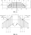
FIG. 1a is a schematic diagram of a waveform of terminal voltage at the winding of phase A in the zero-crossing detection of BEMF in the related art; -
FIG. 1b is a schematic diagram of a waveform of terminal voltage of phase A in the zero-crossing detection of BEMF in the related art; -
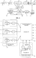
FIG. 2 is a schematic structural diagram of a hardware system with BLDC applied to an electronic device according to an embodiment of the present disclosure; -
FIG. 3 is a schematic diagram of an ideal waveform of BEMF and the numbering of sectors of the BLDC motor according to an embodiment of the present disclosure; -
FIG. 4 is a flowchart of a method for determining BEMF zero-crossing thresholds of a BLDC motor according to an embodiment of the present disclosure; -
FIG. 5 is a schematic structural diagram of a hardware system with BLDC applied to an electronic device according to an embodiment of the present disclosure; -
FIG. 6 is a schematic structural diagram of a system for determining BEMF zero-crossing thresholds of a BLDC motor according to an embodiment of the present disclosure; -
FIG. 7 is a schematic diagram of modules for implementing a method for determining BEMF zero-crossing thresholds of a BLDC motor according to an embodiment of the present disclosure; -
FIG. 8 is a schematic diagram of a relationship between an actual BEMF signal model and an ideal BEMF signal model resulting from shifts of resistances of voltage-divider resistors for the three-phase terminal voltages according to an embodiment of the present disclosure; -
FIG. 9 is a schematic diagram of an equivalent structure of a control algorithm of a controller according to an embodiment of the present disclosure; -
FIG. 10 is a schematic diagram of a relationship between an actual BEMF signal model and an ideal BEMF signal model generated by asymmetry of resistances and inductances of a motor according to an embodiment of the present disclosure; -
FIG. 11 is a flowchart of commutation implemented by a BLDC motor according to an embodiment of the present disclosure; -
FIG. 12 is a schematic structural diagram of a device for determining BEMF zero-crossing thresholds of a BLDC motor according to an embodiment of the present disclosure; -
FIG. 13 is a schematic diagram of hardware structure of a device for determining BEMF zero-crossing thresholds of a BLDC motor according to an embodiment of the present disclosure; -
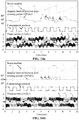
FIG. 14a is a schematic diagram showing commutation positions at which resistances of voltage-divider resistors for the three-phase terminal voltages are shifted and the resistances and inductances of the motor are asymmetric, without using the scheme of the embodiment of the present disclosure; and -
FIG. 14b is a schematic diagram showing commutation positions at which resistances of voltage-divider resistors for the three-phase terminal voltages are shifted and the resistances and inductances of the motor are asymmetric, using the scheme of the embodiment of the present disclosure. - To make the objective, technical solution, and advantages of the embodiments of the present disclosure clearer, specific technical solutions of the present disclosure are further described in detail below in conjunction with the accompanying drawings of the embodiments of the present disclosure. The following examples serve to illustrate the present disclosure, but are not intended to limit the scope of the present disclosure.
- As described above, in the related art, when controlling the BLDC, the BEMF of the BLDC is sampled for multiple times using the acquisition function of the ADC module during the high level of the PWM control period, and whether the BEMF crosses zero is determined by comparing the terminal voltage of the suspended phase and the reference voltage of BEMF after the sampling is completed. Taking phase A as an example, during a mechanical period of the body of the motor, the waveform of terminal voltage at the winding of phase A is shown in
FIG. 1a , where phase A is suspended during BC and CB, and the waveform of terminal voltage thereof is shown inFIG. 1b . While the PWM is turned on, the terminal voltage of phase A is UA=eA+Vdc/2 (where eA is the BEMF of phase A, and Vdc/2 is the reference voltage of BEMF). When UA= Vdc/2, eA=0, which is the zero-crossing time of the BEMF of phase A. At time a1 inFIG. 1b , UA<Vdc/2, the BEMF does not cross zero, and at time a2 in the next PWM control period, UA>Vdc/2, at which it is detected that the BEMF has crossed zero. Similarly, during CB, the terminal voltage of phase A tends to decrease. At time b2, UA>Vdc/2, the BEMF does not cross zero, and at time b3, UA<Vdc/2, at which it is detected that the BEMF has cross zero. - In the related art, the premise of using the scheme of zero-crossing detection of BEMF is that resistances of voltage-divider resistors for the three-phase terminal voltages are fixed, and the resistances and inductances of the motor are fully symmetrical. However, in practical processes, the following phenomenon occurs:
- 1. The resistances of the voltage-divider resistors for the three-phase terminal voltages would change due to external factors such as a temperature rise or aging, such that the ratio of voltage dividing is shifted, thereby affecting the accuracy of the terminal voltage detection. Upon the abovementioned phenomenon, there is a deviation between the terminal voltage obtained through sampling by the voltage-divider resistor and the actual value of the terminal voltage.
- 2. Since the resistance and inductance of the high-speed motor are small, there is easily asymmetry of the resistance and inductance in the actual manufacturing process. This may be caused by modular manufacturing, asymmetric turns, and unequal contact resistances in the circuits. Upon the abovementioned phenomenon, there is a deviation between the terminal voltage of the suspended phase and the BEMF signal thereof.
- In case of the abovementioned two phenomena, the conventional sensorless BLDC driving method based on zero-crossing detection for BEMF is affected by the following non-ideal factors: the shifts of the resistances of the voltage-divider resistors for the three-phase terminal voltages, and the asymmetry of the resistances and inductances of the motor. In case of the abovementioned two non-ideal phenomena, the zero-crossing signal of the terminal voltage is shifted and eventually causes a commutation error, which affects the driving performance.
- In view of the above, in the embodiments of the present disclosure, the time interval between BEMF zero-crossing points of two adjacent sectors of the BLDC motor is detected to obtain at least two first time intervals; the errors of the BEMF zero-crossing points is obtained by using the obtained at least two first time intervals; the determined errors of the BEMF zero-crossing points are converged to obtain the correction increments of the BEMF zero-crossing thresholds; the BEMF zero-crossing thresholds are determined by using the obtained correction increments of the BEMF zero-crossing thresholds, and the positions of the BEMF zero-crossing points may be accurately detected according to the determined BEMF zero-crossing thresholds, such that the commutation accuracy may be improved.
-
FIG. 2 is a schematic structural diagram of a hardware system with BLDC applied to an electronic device. As shown inFIG. 2 , the hardware system includesBLDC 201, voltage-divider resistors 202 for three-phase terminal voltages, a three-phasefull bridge 203, acapacitor 204, abattery 205, acurrent sampling resistance 206, and a MicroController Unit (MCU) 207. TheMCU 207 controls the three-phasefull bridge 203 through a drive signal, thereby controlling theBLDC 201. The three phases ofBLDC 201 are respectively connected to three groups of voltage-divider resistors, i.e., the voltage-divider resistors 202 for three-phase terminal voltages, and the three-phase terminal voltages are acquired through an ADC module inMCU 207. Resistances and inductances are provided inBLDC 201. - The embodiment of the disclosure provides an improved strategy for the impact of the shift of the resistances of the voltage-
divider resistors 202 for the three-phase terminal voltages, and/or the asymmetry of the resistances and inductances in theBLDC 201. -
FIG. 3 is a schematic diagram of an ideal waveform of BEMF and the numbering of sectors of the BLDC motor. InFIG. 3 ,waveform 301, waveform 302 andwaveform 303 are waveforms of BEMF of phase A, phase B and phase C of the BLDC, respectively. The phase difference among the three phases is 120° and the mechanical period of one motor body includes six sectors numbered assector 1,sector 2,sector 3,sector 4,sector 5 andsector 6. The sector boundary is the angular position at which the BLDC commutates. In an ideal state, the angular interval between the sectors is 60°. - The angular position of the commutation is spaced by 30° from the angular position of the BEMF zero-crossing point, and the mechanical period of one motor body includes six intervals between the BEMF zero-crossing points. In an ideal state, the angular interval between the BEMF zero-crossing points of two adjacent sectors is 60°. However, when the resistances and inductances of the motor are asymmetric or the resistances of the voltage-divider resistors for the three-phase terminal voltages change, the angular positions of the zero-crossing points of the terminal voltage signals are shifted, and the interval between the BEMF zero-crossing points of two adjacent sectors is no longer 60°, which leads to the commutation error caused by the BLDC and reduces the driving performance. In practical applications, the time interval between the BEMF zero-crossing points is easily detected by software, and the time interval t between the BEMF zero-crossing points and the angle θ of the BEMF zero-crossing point have a corresponding relationship as shown in Equation 1 (here, θ and t refer to the same abscissa region in
FIG. 3 ).
- Therefore, in the embodiment of the disclosure, the scheme starts from detecting the actual time interval between the BEMF zero-crossing points, and aims to correct, through a series of correction means, the interval between the BEMF zero-crossing points of adjacent sectors into uniform 60° .
- An embodiment of the present disclosure provides a method for determining BEMF zero-crossing thresholds of a BLDC motor. As shown in
FIG. 4 , the method includes steps S101 to S104. - In S101, a time interval between BEMF zero-crossing points of two adjacent sectors of the BLDC motor is detected to obtain at least two first time intervals.
- Here, in practical applications, the BLDC of the embodiment of the present invention employs a sensorless drive control technique.
- When the BLDC has six sectors, the time interval between the BEMF zero-crossing points of two adjacent sectors refers to the time interval between the BEMF zero-crossing points of six adjacent sectors in
FIG. 3 , the six adjacent intervals between the BEMF zero-crossing points are numbered as t 12 , t 23 , t 34 , t 45 , t 56 and t61, which together constitute the duration of the mechanical period of the motor body. Herein, the subscripts of the numbering represent the numbering of the sectors, for example, t 12 represents the time interval between the BEMF zero-crossing points ofadjacent sectors - In practical applications, the time interval between the BEMF zero-crossing points of two adjacent sectors of the BLDC may be obtained by a timer.
- In S102, errors of the BEMF zero-crossing points are determined by using the obtained at least two first time intervals.
- Here, the error of the BEMF zero-crossing point is a signal of difference between the actual BEMF signal and the ideal BEMF signal after the BEMF of BLDC is shifted due to non-ideal factors. The error of the BEMF zero-crossing point is determined by using the relationship between the ideal BEMF signal and the actual BEMF signal that has been shifted compared to the ideal BEMF signal, and the error of the BEMF zero-crossing point may be calculated according to the obtained at least two first time intervals.
- In practical applications, as previously described, the non-ideal factors may include the shifts of the resistances of the voltage-divider resistors for the three-phase terminal voltages and/or the asymmetry of the resistances and inductances of the motor.
- In S103, the determined errors of the BEMF zero-crossing points are converged to obtain correction increments of the BEMF zero-crossing thresholds.
- Here, the converging refers to processing the determined errors of the BEMF zero-crossing points, such that the errors of the BEMF zero-
crossing points approach 0, thereby eliminating the errors. There are many technical means for converging the errors of the BEMF zero-crossing points, such as using a controller. - Here, the correction increments of the BEMF zero-crossing thresholds are correction values applied to the shifts of the BEMF zero-crossing points due to non-ideal factors, such as a small vertical correction amount of the BEMF near Vdc / 2 as shown in
FIG. 1b . - In S104, BEMF zero-crossing thresholds are determined by using the obtained correction increments of the BEMF zero-crossing thresholds, the determined BEMF zero-crossing thresholds being configured to determine whether respective BEMFs cross zero.
- Here, in practical applications, when the BLDC has six sectors, the zero-crossing thresholds of BEMF are zero-crossing thresholds τ 1, τ 2, τ 3, τ 4, τ 5 and τ 6 of BEMF among the six adjacent sectors, i.e., the actual value of BEMF shown in
FIG. 1b . The BEMF zero-crossing thresholds obtained in the present embodiment of the present disclosure may provide an accurate commutation basis to the motor, so as to eliminate commutation errors caused by non-ideal factors. - According to the method for determining BEMF zero-crossing thresholds of a BLDC motor, a time interval between BEMF zero-crossing points of two adjacent sectors of the BLDC motor is detected to obtain at least two first time intervals; errors of the BEMF zero-crossing points are determined by using the obtained at least two first time intervals; the determined errors of the BEMF zero-crossing points are converged to obtain correction increments of the BEMF zero-crossing thresholds; and BEMF zero-crossing thresholds are determined by using the obtained correction increments of the BEMF zero-crossing thresholds. Since the errors of the BEMF zero-crossing points of the BLDC are determined, the actual BEMF zero-crossing thresholds are determined, such that the positions of the BEMF zero-crossing points may be accurately detected, the driving performance of the BLDC is ensured, and the reliability of the product is improved. Furthermore, according to the scheme in the embodiment of the disclosure, the commutation errors caused by non-ideal factors are eliminated through merely a software algorithm, i.e., an algorithm for determining BEMF zero-crossing thresholds, without increasing hardware costs, and the scheme is easy to implement.
- In practical applications, when the resistances of the voltage-divider resistors for the three-phase terminal voltages are shifted, and the resistances and inductances of the motor are symmetrical, it is possible to eliminate merely the influence caused by the shifts of the resistances of the voltage-divider resistors for the three-phase terminal voltages.
- In view of the above, in one embodiment, in S102 and S103, determining the errors of the BEMF zero-crossing points by using the obtained at least two first time intervals includes:
- determining a first error of each phase of the BLDC motor by using the obtained at least two first time intervals in combination with a relationship between a half-period angle of a first BEMF signal and a corresponding half-period angle of a second BEMF signal, so as to obtain a first set of errors, wherein the first BEMF signal is an ideal BEMF signal, and the second BEMF signal is an actual BEMF signal; and
- converging errors in the first set of errors to obtain the correction increments of the BEMF zero-crossing thresholds.
- Here, in practical applications, such errors may be referred to as vertical errors.
- When the resistances of the voltage-divider resistors for the three-phase terminal voltages are not shifted, and the resistances and inductances of the motor are asymmetric, it is possible to eliminate merely the influence of the asymmetry caused by the resistances and inductances of the motor.
- In view of the above, in one embodiment, in S102 and S103, determining the errors of the BEMF zero-crossing points by using the obtained at least two first time intervals includes:
- determining a second error of each phase of the BLDC motor by using the obtained at least two first time intervals in combination with a relationship between a zero point angle interval of two adjacent sectors of a first BEMF signal and a zero point angle interval of two corresponding adjacent sectors of a second BEMF signal, so as to obtain a second set of errors, wherein the first BEMF signal is an ideal BEMF signal, and the second BEMF signal is an actual BEMF signal; and
- converging errors in the second set of errors to obtain the correction increments of the BEMF zero-crossing thresholds.
- Here, in practical applications, such errors may be referred to as horizontal errors.
- When resistances of the voltage-divider resistors for the three-phase terminal voltages are shifted, and the resistances and inductances of the motor are asymmetric, the influence caused by these two factors needs to be eliminated.
- In view of the above, in an embodiment, in S102 to 104, determining the errors of the BEMF zero-crossing points by using the obtained at least two first time intervals includes:
- determining a first error of each phase of the BLDC motor by using the obtained at least two first time intervals in combination with a relationship between a half-period angle of a first BEMF signal and a corresponding half-period angle of a second BEMF signal, so as to obtain a first set of errors; and determining a second error of each phase of the BLDC motor by using the obtained at least two first time intervals in combination with a relationship between a zero point angle interval of two adjacent sectors of the first BEMF signal and a zero point angle interval of two corresponding adjacent sectors of the second BEMF signal, so as to obtain a second set of errors, wherein the first BEMF signal is an ideal BEMF signal, and the second BEMF signal is an actual BEMF signal;
- converging errors in the first set of errors to obtain first correction increments of the BEMF zero-crossing thresholds, and converging errors in the second set of errors to obtain second correction increments of the BEMF zero-crossing thresholds; and
- determining the BEMF zero-crossing thresholds by using the first correction increments of the BEMF zero-crossing thresholds and the second correction increments of the BEMF zero-crossing thresholds.
- In one embodiment, determining a first error of each phase of the BLDC motor by using the obtained at least two first time intervals in combination with a relationship between a half-period angle of a first BEMF signal and a corresponding half-period angle of a second BEMF signal includes:
- determining, using the obtained at least two first time intervals, time intervals of BEMF zero-crossing points of sectors corresponding to a half period of a mechanical period a body of of the BLDC motor, so as to obtain at least two second time intervals; and
- determining the first error of each phase of the BLDC motor by using the obtained at least two second time intervals in combination with the relationship between the half-period angle of the first BEMF signal and the corresponding half-period angle of the second BEMF signal.
- The present disclosure is described in detail below in connection with specific application examples.
- In an application embodiment, the BLDC has 6 sectors and is implemented using the hardware system with the BLDC applied to the electronic device as shown in
FIG. 5 . As shown inFIG. 5 , the system includesBLDC 501, voltage-divider resistors 502 for three-phase terminal voltages, a three-phasefull bridge 503, acapacitor 504, abattery 505, acurrent sampling resistance 506 and aMCU 507. - The composition shown in
FIG. 5 is similar to the composition shown inFIG. 2 , except that the voltage-divider resistors 502 for three-phase terminal voltages. The BEMF sampling scheme based on the resistance divider is used inFIG. 2 , and the BEMF sampling scheme based on the virtual neutral-point is used inFIG. 5 . Although the BEMF sampling scheme based on the resistance divider used inFIG. 2 is not employed inFIG. 5 , in practical applications, the system shown inFIG. 5 may also suffer from the asymmetry of the resistances and inductances of the motor and the shifts of the resistances of the voltage-divider resistors for the three-phase terminal voltages (the shifts of the resistances of the voltage-divider resistors502 for the three-phase terminal voltages). Here, the shifts of the resistances of the voltage-divider resistors for the three-phase terminal voltages may be represented by: shifts in the resistances at the terminals of three phases, or other situations equivalent to a shift in the resistances, such as the situations that the voltage drops of three phases at the branch side are inconsistent, and the on-state voltage drops of the switching tubes in the branches are inconsistent. - In an application embodiment, a system for determining BEMF zero-crossing thresholds of a BLDC motor shown in
FIG. 6 is used. As shown inFIG. 6 , the control system includes a rotational speed loop controller 601, a current loop controller 602, a commutation logic module 603, a PWM module 604, a three-phase full bridge 605, a BLDC 606, a timer B 607, a timer A 608, analgorithm module 609 for determining the BEMF zero-crossing thresholds, a zero-crossingdetection module 610, anADC sampling module 611 and a voltage-divider resistor module 612 for the three-phase terminal voltages. - The time interval between the BEMF zero-crossing points of BLDC is measured at least six times continuously by timer A 608, to obtain six time intervals between the BEMF zero-crossing points within the duration of one mechanical period of the body of the motor, and then the most recent six measured time intervals t12, t23, t 34 , t 45 , t 56 and t61 between the zero-crossing points of two adjacent sectors are input to the
algorithm module 609 for determining the BEMF zero-crossing thresholds, so as to generate the BEMF zero-crossing thresholds by thealgorithm module 609 for determining the BEMF zero-crossing thresholds. - The ADC sampling module 611 (corresponding to the function of the voltage-
divider resistors 502 for three-phase terminal voltages inFIG. 5 and the function of BEMF sampling of MCU 507) acquires the terminal voltages in real time during the high level of the PWM module 604 through the voltage-divider resistor module 612 (corresponding to the voltage-divider resistors 502 for three-phase terminal voltages inFIG. 5 ). The differences between the acquired terminal voltage signals and the above-mentioned BEMF zero-crossing thresholds are obtained and inputted to the zero-crossing detection module 610 (corresponding to the function of zero-crossing detection ofMCU 507 inFIG. 5 ) . When the difference between the terminal voltage signal and the BEMF zero-crossing threshold is 0, the BEMF zero-crossing point occurs. Each time the BEMF zero-crossing point occurs, the timer B 607 first enables the 30° delay and the commutation logic module 603 is triggered. Starting from measuring the time interval between the BEMF zero-crossing points of the BLDC, the above processes are cyclically performed in the control system. The zero-crossing threshold is calculated each time by thealgorithm module 609 for determining the BEMF zero-crossing thresholds, and is used to determine the occurrence of zero-crossing point in the next mechanical period of the body of the motor. As such, the position of the BEMF zero-crossing point may be accurately detected, and the commutation accuracy may be greatly improved. - It is to be noted that the structure shown in
FIG. 6 employs a double closed-loop (for rotational speed and current) control structure, i.e., rotational speed loop controller 601 and current loop controller 602, to implement system functions. The difference between the given rotational speed signal and the feedback rotational speed signal is obtained, and the constant current signal is output to current controller 602 through rotational speed controller 601. Then the difference between the constant current signal and the feedback current signal is obtained, and the voltage signal is output to the commutation logic module. Finally BLDC 606 is driven through PWM module 604 and three-phase full bridge 605. The double closed-loop (for rotational speed and current) control structure may be extended to any structure, such as a rotational speed single loop or double closed-loop for power and current. That is, rotational speed loop controller 601 and current loop controller 602 may be replaced by the rotational speed loop controller only, or the power loop controller and the current loop controller, or other equivalent structures capable of achieving the functions herein, depending on actual application requirements. - In an application embodiment, the algorithm for determining BEMF zero-crossing thresholds of a BLDC motor shown in
FIG. 7 is specifically employed to correct the BEMF zero-crossing thresholds of the BLDC motor. - As shown in
FIG. 7 , the correction algorithm mainly includes a vertical correction algorithm, a horizontal correction algorithm, and a threshold feedback algorithm. Herein, the vertical correction algorithm is mainly used to calculate a vertical error (an error caused by the shifts of resistances of the voltage-divider resistors for the three-phase terminal voltages); the horizontal correction algorithm is mainly used to calculate a horizontal error (an error caused by asymmetry of the resistances and inductances of the motor); the threshold feedback algorithm is mainly used to determine the actual BEMF zero-crossing thresholds. - In practical applications, the processor may use both the vertical correction algorithm and the horizontal correction algorithm to calculate corresponding errors, which do not affect each other and are respectively responsible for correcting commutation errors caused by different non-ideal factors. In practical applications, when there is an influence of only one non-ideal factor in a specific application, i.e., there are only shifts of resistances of voltage-divider resistors for the three-phase terminal voltages or an asymmetry of the resistances and inductances of the motor, one of the correction algorithms may be separately used to realize the correction function correspondingly. Since the situation is the most complicated and any one of the correction modules described above should be adopted when two non-ideal factors are present, the implementation of the three-part correction algorithm when two non-ideal factors are present is described in detail herein. It is to be understood by those skilled in the art that when only one non-ideal factor is present, one of the vertical correction algorithm and the horizontal correction algorithm may be correspondingly employed in conjunction with the threshold feedback algorithm to correct the BEMF zero-crossing thresholds.
- Each of the algorithms of
FIG. 7 is described in detail below. - The vertical correction algorithm is first described in detail.
- Ideally, the BEMF signals obtained from the terminal voltages will be distributed symmetrically on both sides of V dc /2. That is, the BEMF signals of
half period 180° are evenly distributed on both sides of Vdc /2. When the resistances of the voltage-divider resistors for the three-phase terminal voltages are shifted, there is a direct current deviation between the terminal voltage signal and the ideal design value after the voltage dividing, which is manifested in that the actual BEMF signals are no longer uniformly distributed on both sides of V dc /2, but a certain vertical offset is generated on the basis of the ideal BEMF signal, thereby causing a zero-crossing detection error. -
FIG. 8 shows the relationship between the actual BEMF signal model and the ideal BEMF signal model resulting from the shifts of resistances of the voltage-divider resistors for the three-phase terminal voltages. Here, 801 is an ideal BEMF signal model of phase B (a phase of a random example), and 802 is an actual BEMF signal model of phase B after a vertical offset is generated due to the shifts of the resistances of the voltage-divider resistors for the three-phase terminal voltages. Correspondingly, in phase B, the upper half-period angle and the lower half-period angle of the ideal BEMF signal are respectively represented by θ 25 and θ 52; the upper half-period angle and the lower half-period angle of the actual BEMF signal are represented by θ̂ 25 and θ̂ 52, respectively. The vertical error of the BEMF zero-crossing point of phase B is represented by εVB. - In
FIG. 8 , there is the following basic relationship:
- Since θ 25 = θ52 = π, it may be obtained:

- When the upper half-period time interval of phase B is denoted by t25 and the lower half-period time interval of phase B is denoted by t52, the relationship between θ̂25 and t25 and the relationship between θ̂52 and t52 are as follows:

- Substituting formula (4) into formula (3), it may be obtained:

- Similarly, for the other two phases (phase A and phase C), the vertical errors of the BEMF zero-crossing points are:


- Here, it may be seen from the above derivation that, according to the relationship between the half-period angle of the ideal BEMF signal and the corresponding half-period angle of the actual BEMF signal, for each phase of the BLDC, the relationship between the vertical error of the BEMF zero-crossing point caused by the shifts of the resistances of the voltage-divider resistors for the three-phase terminal voltages and the time interval of the BEMF zero-crossing points is obtained, such that the vertical error is determined through software.
- According to the time interval between the BEMF zero-crossing points of the BLDC measured by the timer for six consecutive times, six time intervals t12, t23, t 34 , t 45 , t 56 and t 61 between the BEMF zero-crossing points in one mechanical period of a body of the motor are obtained, then two time intervals t 36 and t 36 , t 25 and t 52, and t 14 and t 41 between the BEMF zero-crossing points of two half-periods corresponding to phase A, phase B and phase C are obtained.
- The two time intervals between the BEMF zero-crossing points of two half-periods corresponding to phase A, phase B and phase C are calculated according to the above-mentioned relationship, and the vertical errors of the BEMF zero-crossing points of each phase of the BLDC is obtained. Here, a set of vertical errors (i.e., a first set of errors) of the BEMF zero-crossing points caused by the shifts of the resistances of the voltage-divider resistors for the three-phase terminal voltages are determined.
- The vertical errors of the BEMF zero-crossing points of the BLDC for phase A, phase B and phase C are respectively input to the controller. Here, the controller may use the PI controller to converge the error signals of the BEMF zero-crossing points according to the classical PI parameter tuning method, so as to eliminate the errors.
- The PI controller may be specifically implemented in combination with an equivalent structure of a control algorithm of a controller shown in
FIG. 9 , and the PI controller for each phase may be implemented by using the equivalent structure of the control algorithm ofFIG. 9 . - The open-loop transfer function GOL is:

- Here, kp and ki is the PI proportional and integral gain; ω is the motor speed, λ is the permanent magnet flux, and tperiod is the mechanical period of the body of the motor. According to the classical PI parameter tuning method, kp and ki may be set to:


- Here, ω c is the desired control bandwidth angular frequency. For example, when the bandwidth is 10 Hz,


- Here, the vertical errors of the BEMF zero-crossing points of the BLDC for phases A, B and C are input to the PI controller, and the vertical correction increments τ VA, τ VB and τ VC of the BEMF zero-crossing thresholds are obtained.
- The horizontal correction algorithm is described in detail below.
FIG. 10 illustrates the relationship between the actual BEMF signal model and the ideal BEMF signal model generated by asymmetry of resistances and inductances of a motor. InFIG. 10 , 1001, 1002 and 1003 are ideal BEMF signal models for phases A, B and C, respectively; 1004, 1005 and 1006 are actual BEMF signal models for phase A, phase B and phase C respectively after the horizontal offsets are generated due to the asymmetry of resistances and inductances of the motor; θ 12 , θ 23, θ 34, θ 45, θ 56 and θ 61 are the angular intervals of the zero-crossing points of the ideal BEMF signal between two adjacent sectors; θ̂ 12' θ̂ 23, θ̂ 34, θ̂ 45, θ̂ 56 and θ̂ 61 are the angular intervals of the zero-crossing points of the actual BEMF signal between two adjacent sectors; and εHA, εHB and εHC are the horizontal errors of the BEMF zero-crossing points for phases A, B and C, respectively. - When the resistances and inductances of the motor are asymmetric, for example, as shown in
FIG. 10 , when the impedance for phase A is greater than the impedance for phase B (two phases randomly exemplified), the terminal voltage forsector 2 is smaller than the ideal value; and the terminal voltage forsector 5 is greater than the ideal value. In particular, the actual BEMF signal for phase C is shifted to the right compared to the ideal BEMF signal for phase C (from 1002 to 1005 inFIG. 10 ). It may therefore be inferred that: - the BEMF signal for phase C is affected by the resistances and inductances for phases A and B;
- the BEMF signal for phase B is affected by the resistances and inductances for phases A and C; and
- the BEMF signal for phase A is affected by the resistances and inductances for phases B and C.
- The specific effect is manifested as a lead or a lag, depending on the relative magnitudes of the corresponding resistances and inductances.
- In
FIG. 10 , there is the following basic relationship:
- Furthermore, according to the characteristics caused by the asymmetric of the resistances and inductances of the motor, when the impedance for phase A (for example, in
FIG. 10 ) is larger than the impedance for phase B, the BEMF signal for phase C is shifted to the right (lagging); and when the impedance for phase A is smaller than the impedance for phase B, the BEMF signal for phase C is shifted to the left (leading). Due to the periodicity of the logic, it may be concluded that the sum of the shifts of three phases is zero, i.e., there is a relationship as follows:
- All of θ 12 to θ 61 are


- According to the relationship illustrated in
FIG. 10 , the variables in parentheses and outside parentheses in Equation 13 have the same values theoretically, i.e., θ̂ 12 =θ̂ 45, θ̂ 23 =θ̂ 56 and θ̂ 34 = θ̂ 61, and according to the corresponding relationship (Equation 1) between the time interval between the BEMF zero-crossing points and the angles of the BEMF zero-crossing points, a formula for calculating the equivalent error inEquation 10 may be obtained:
- Here, it may be seen from the above derivation that, according to the relationship between the angular interval of zero-crossing points of two adjacent sectors of the ideal BEMF signal and the angular interval of zero-crossing points of two corresponding adjacent sectors of the actual BEMF signal, the relationship, for each phase of the BLDC, between the horizontal errors of the BEMF zero-crossing points caused by the asymmetry of the resistances and inductances of the motor, and the time interval of the BEMF zero-crossing points is obtained, and thus the horizontal error is determined by software.
- It is to be noted that, in practical applications, the relationship between phase A and phase B is not necessarily related to these two phases, but may be related to two random phases of the three phases. However, it should be noted that when the two phases in
relationship 14 are no longer phase A and phase B, but other two phases, the corresponding time interval of the BEMF zero-crossing points needs to be adjusted, and a specific adjustment method may be obtained through referring to the above process. - According to the time interval of the BEMF zero-crossing points of the BLDC measured by the timer for six consecutive times, six time intervals t 12, t23, t 34 , t 45 , t 56 and t61 of the BEMF zero-crossing points in one mechanical period of a body of the motor are obtained, and then two time intervals of the BEMF zero-crossing points corresponding to phase A and phase B are obtained: t 12+t 45 and t 23+t 56; and t 12+t 45 and t 34+t 61, respectively.
- The two time intervals of the BEMF zero-crossing points corresponding to phase A and phase B are calculated according to the abovementioned relationship, and the horizontal errors of the BEMF zero-crossing points for phase A and phase B of the BLDC are obtained. The horizontal error of the BEMF zero-crossing point for phase C is a number opposite to the sum of the horizontal errors of the BEMF zero-crossing points for phase A and phase B, i.e., the set of horizontal errors of the BEMF zero-crossing points caused by the asymmetry of the resistances and inductances of the motor (i.e., the second set of errors) is determined.
- The horizontal errors of the BEMF zero-crossing points for phase A, phase B and phase C of the BLDC are input to the controller respectively. Here, the controller may adopt the PI controller, and according to the classical PI parameter tuning method, the error signals of the BEMF zero-crossing points may be converged, so as to eliminate the error.
- The specific implementation of the PI controller is the same as that in the vertical correction algorithm, and details are not described herein.
- Here, the vertical errors of the BEMF zero-crossing points for phase A, phase B and phase C of the BLDC are input to the PI controller to obtain the horizontal correction increments τ HA, τ HB and τ HC of the BEMF zero-crossing thresholds.
- The threshold feedback algorithm is described in detail below.
- Here, the BEMF zero-crossing thresholds are determined by using the vertical correction increments of the BEMF zero-crossing thresholds and the horizontal correction increments of the BEMF zero-crossing thresholds.
- Here, when the direction of the zero-crossing point is from positive to negative, the BEMF zero-crossing threshold is obtained by making a difference between the vertical correction increment of the BEMF zero-crossing threshold and the horizontal correction increment of the BEMF zero-crossing threshold; and when the direction of the zero-crossing point is from negative to positive, the BEMF zero-crossing threshold is obtained by summing the vertical correction increment of the BEMF zero-crossing threshold with the horizontal correction increment of the BEMF zero-crossing threshold.
- The correction increment of the BEMF zero-crossing threshold is then summed with the reference voltage of the BEMF zero-crossing point to obtain the corrected BEMF zero-crossing threshold.
- Here, the calculation of the six zero-crossing thresholds τ 1 to τ 6 corresponding to the six sectors is as follows:

- In
Equation 15, the horizontal correction increments of the BEMF zero-crossing thresholds are subtracted insectors sectors FIG. 10 as an example, the actual zero-crossing signal detected is ahead of the ideal zero-crossing point by a phase of εHA. When the threshold ofsector 6 is increased and the threshold ofsector 3 is decreased, the actual zero-crossing position may be moved to the right at the same time. When εHA is converged to 0, the actual zero-crossing position coincides with the ideal zero-crossing position. - It is to be noted that, when only the threshold correction corresponding to the vertical correction or the horizontal error is performed according to the actual situation, it is necessary to remove the unused corresponding correction increments of the BEMF zero-crossing thresholds in
equation 15. -
FIG. 11 is a flowchart of commutation implemented by a BLDC motor according to an embodiment of the present disclosure. As shown inFIG. 11 , the flow includes (1)-(9). - (1) It is detected that the BEMF crosses zero.
- (2) The processes of stopping, reading and restarting timer A are performed to obtain the time intervals t12, t 23 , t 34 , t 45, t 56 and t 61, of the zero-crossing points.
- (3) The vertical correction is performed to obtain τ VA, τ VB and τ VC.
- (4) The horizontal correction is performed to obtain τ HA, τ HE and τ HC.
- (5) The threshold feedback calculation is performed to obtain τ 1 and τ 6;
- (6) τ 1- τ 6 are compared with the terminal voltage to determine whether respective BEMFs cross zero.
- (7) When the determination result is that the BEMF crosses zero, timer B is set and started.
- (8) The commutation is performed according to the commutation sequence.
- (9) Timer B is stopped.
- By repeatedly performing the above-mentioned operations (1) to (9), an accurate commutation of BLDC may be realized.
- As may be seen from the above description, in the embodiment of the disclosure, through measuring the time interval between zero-crossing points of adjacent sectors, the error between each zero-crossing point and the ideal position is reconstructed according to the mathematical relationship. Then, the PI controller continuously adjusts the BEMF zero-crossing thresholds such that each zero-crossing point is converged to a desired position, thereby improving the commutation accuracy. The correction is divided into two parts, of which the vertical correction part is responsible for correcting the commutation error caused by the shifts of the resistances of the voltage-divider resistors; and the horizontal correction part is responsible for correcting the commutation error caused by the asymmetry of the resistances and inductances of the motor. The two sets of controllers may operate at the same time without affecting each other, thereby eliminating the errors finally.
- In order to implement the method of the embodiment of the present disclosure, the embodiment of the present disclosure further provides a device for determining BEMF zero-crossing thresholds of a BLDC motor.
FIG. 12 is a structural diagram of the device of the embodiment of the present disclosure. As shown inFIG. 12 , thedevice 1200 includes a detectingunit 1201, a first determiningunit 1202, a second determiningunit 1203 and a third determiningunit 1204. - The detecting
unit 1201 is configured to detect a time interval between BEMF zero-crossing points of two adjacent sectors of the BLDC motor to obtain at least two first time intervals. - The first determining
unit 1202 is configured to determine errors of the BEMF zero-crossing points by using the obtained at least two first time intervals. - The second determining
unit 1203 is configured to converge the determined errors of the BEMF zero-crossing points to obtain correction increments of the BEMF zero-crossing thresholds. - The third determining
unit 1204 is configured to determine the BEMF zero-crossing thresholds by using the correction increments of the BEMF zero-crossing thresholds, the determined BEMF zero-crossing thresholds being configured to determine whether respective BEMFs cross zero. - In one embodiment, the first determining
unit 1201 is configured to determine a first error of each phase of the BLDC motor by using the obtained at least two first time intervals in combination with a relationship between a half-period angle of a first BEMF signal and a corresponding half-period angle of a second BEMF signal, so as to obtain a first set of errors. Herein, the first BEMF signal is an ideal BEMF signal, and the second BEMF signal is an actual BEMF signal. - The second determining
unit 1202 is configured to converge errors in the first set of errors to obtain the correction increments of the BEMF zero-crossing thresholds. - In one embodiment, the first determining
unit 1201 is configured to determine a second error of each phase of the BLDC motor by using the obtained at least two first time intervals in combination with a relationship between a zero point angle interval of two adjacent sectors of a first BEMF signal and a zero point angle interval of two corresponding adjacent sectors of a second BEMF signal, so as to obtain a second set of errors. Herein, the first BEMF signal is an ideal BEMF signal, and the second BEMF signal is an actual BEMF signal. - The second determining
unit 1202 is configured to converge errors in the second set of errors to obtain the correction increments of the BEMF zero-crossing thresholds. - In one embodiment, the first determining
unit 1201 is configured to: determine a first error of each phase of the BLDC motor by using the obtained at least two first time intervals in combination with a relationship between a half-period angle of a first BEMF signal and a corresponding half-period angle of a second BEMF signal, so as to obtain a first set of errors; and determine a second error of each phase of the BLDC motor by using the obtained at least two first time intervals in combination with a relationship between a zero point angle interval of two adjacent sectors of the first BEMF signal and a zero point angle interval of two corresponding adjacent sectors of the second BEMF signal, so as to obtain a second set of errors. Herein, the first BEMF signal is an ideal BEMF signal, and the second BEMF signal is an actual BEMF signal. - The second determining
unit 1202 is configured converge errors in the first set of errors to obtain first correction increments of the BEMF zero-crossing thresholds; and converge errors in the second set of errors to obtain second correction increments of the BEMF zero-crossing thresholds. - A third determining
unit 1203 configured to determine the BEMF zero-crossing thresholds by using the first correction increments of the BEMF zero-crossing thresholds and the second correction increments of the BEMF zero-crossing thresholds. - In practical applications, the detecting
unit 1201, the first determiningunit 1202, the second determiningunit 1203 and the third determiningunit 1204 may be implemented by a processor in the device for determining the BEMF zero-crossing thresholds of the BLDC motor. - It should be noted that the device for determining the BEMF zero-crossing thresholds of the BLDC motor provided in the above-described embodiment is described by way of example only with respect to the partitioning of the program modules when determining the BEMF zero-crossing thresholds of the BLDC. In practical applications, the above-described processing may be allocated to different program modules, i.e., the internal structure of the device may be partitioned to different program modules to perform all or part of the processing described above. In addition, the device for determining the BEMF zero-crossing thresholds of the BLDC motor provided in the above-mentioned embodiments and the method embodiments for determining the BEMF zero-crossing thresholds of the BLDC motor belong to the same concept. For the specific implementation thereof, references may be made to the method embodiments, and details are not described herein.
- Based on the hardware implementation of the program modules described above, and in order to implement the methods of the embodiments of the present disclosure, an embodiment of the present disclosure provides a device for determining the BEMF zero-crossing thresholds of the BLDC motor. As shown in
FIG. 13 , the device includes aprocessor 1301 and amemory 1302 configured to store computer programs executable on the processor. - The
processor 1301 is configured to execute the method provided by one or more of the above-described solutions when the computer programs are executed. - In practice, as shown in
FIG. 13 , the components of thedevice 1300 are coupled together by abus system 1303. It will be appreciated thatbus system 1303 is used to implement the connection communication between these components.Bus system 1303 includes, in addition to data bus, power bus, control bus, and status signal bus. For clarity, however, the various bus is labeled asbus system 1303 inFIG. 13 . - In an exemplary embodiment, the embodiment of the disclosure further provides a storage medium. The storage medium is a computer-readable storage medium, such as a
memory 1302 including computer programs executable by theprocessor 1301 of thedevice 1300 for determining the BEMF zero-crossing thresholds of the BLDC motor to perform operations described in the foregoing methods. The computer-readable storage medium may be FRAM (ferromagnetic random access memory), Read Only Memory (ROM), Programmable Read-Only Memory (PROM), Erasable Programmable Read-Only Memory (EPROM), Electrically Erasable Programmable Read-Only Memory (EEPROM), Flash Memory (Flash Memory), magnetic surface memory, optical disk, or memory such as CD-ROM (Compact Disc Read-Only Memory). - To better illustrate that the solution of the embodiments of the disclosure is capable of eliminating errors, an experiment regarding commutation positions is performed.
- The experimental conditions include a BLDC rotation speed ω of 20000 r/min, and the following:
1. The shifts of the resistances of the voltage-divider resistors for the three-phase terminal voltages are shown in Table 1:Table 1 Phase A Phase B Phase C Ratio of actual terminal voltage division to ideal terminal voltage division 110% 100% 90%
2. The asymmetry of the resistances and inductances of the motor is shown in Table 2:Table 2 Phase A Phase B Phase C Resistance RA=38.1 mΩ RB=37.5 mΩ RC=43.5 mΩ Inductance LA=27.5 uH LB=27.2 uH LC=28.6 uH - Thus, the experiment is carried out in the condition of two non-ideal factors, i.e., the resistances of the voltage-divider resistors for the three-phase terminal voltages are shifted and the resistances and inductances of the motor are asymmetric.
-
FIG. 14 illustrates the commutation positions with the scheme in the embodiment of the present disclosure and without the scheme in the embodiment of the present disclosure.FIG. 14a illustrates commutation positions without the scheme in the embodiment of the disclosure, at which the resistances of the voltage-divider resistors for the three-phase terminal voltages are shifted and the resistances and inductances of the motor are asymmetric. It may be seen fromFIG. 14a that, under the influence of two non-ideal factors, the angular interval of the BEMF zero-crossing points of adjacent sectors of the BLDC is not an ideal 60°, the commutation positions are not uniform, and there is a significant fluctuation in the phase current. -
FIG. 14b illustrates commutation positions with the scheme in the embodiment of the disclosure, at which the resistances of the voltage-divider resistors for the three-phase terminal voltages are shifted and the resistances and inductances of the motor are asymmetric. As may be seen fromFIG. 14b , with the scheme in the embodiment of the present disclosure, the angular intervals of the BEMF zero-crossing points of adjacent sectors of the BLDC are all 60°, the commutation positions are uniform, and the phase current fluctuation disappears. Therefore, with the algorithm for determining the BEMF zero-crossing thresholds of the BLDC motor, the error of the BEMF zero-crossing points of the BLDC may be automatically and dynamically corrected. - It should be noted that the terms "first", "second" or the like are used to distinguish among similar objects, rather than describing a specific order or sequence.
- In addition, any combination of the technical solutions described in the embodiments of the present disclosure may be used without conflict.
- The foregoing description is merely illustrative of the preferred embodiments of the present disclosure and is not intended to limit the scope of protection of the present disclosure.
Claims (13)
- A method for determining Back Electromotive Force (BEMF) zero-crossing thresholds of a Brushless Direct Current (BLDC) motor, comprising:detecting a time interval between BEMF zero-crossing points of two adjacent sectors of the BLDC motor to obtain at least two first time intervals;determining errors of the BEMF zero-crossing points by using the obtained at least two first time intervals;converging the determined errors of the BEMF zero-crossing points to obtain correction increments of the BEMF zero-crossing thresholds; anddetermining the BEMF zero-crossing thresholds by using the obtained correction increments of the BEMF zero-crossing thresholds, the determined BEMF zero-crossing thresholds being configured to determine whether respective BEMFs cross zero.
- The method of claim 1, wherein determining the errors of the BEMF zero-crossing points by using the obtained at least two first time intervals comprises:determining a first error of each phase of the BLDC motor by using the obtained at least two first time intervals in combination with a relationship between a half-period angle of a first BEMF signal and a corresponding half-period angle of a second BEMF signal, so as to obtain a first set of errors, wherein the first BEMF signal is an ideal BEMF signal, and the second BEMF signal is an actual BEMF signal; andconverging errors in the first set of errors to obtain the correction increments of the BEMF zero-crossing thresholds.
- The method of claim 1, wherein determining the errors of the BEMF zero-crossing points by using the obtained at least two first time intervals comprises:determining a second error of each phase of the BLDC motor by using the obtained at least two first time intervals in combination with a relationship between a zero point angle interval of two adjacent sectors of a first BEMF signal and a zero point angle interval of two corresponding adjacent sectors of a second BEMF signal, so as to obtain a second set of errors, wherein the first BEMF signal is an ideal BEMF signal, and the second BEMF signal is an actual BEMF signal; andconverging errors in the second set of errors to obtain the correction increments of the BEMF zero-crossing thresholds.
- The method of claim 1, wherein determining the errors of the BEMF zero-crossing points by using the obtained at least two first time intervals comprises:determining a first error of each phase of the BLDC motor by using the obtained at least two first time intervals in combination with a relationship between a half-period angle of a first BEMF signal and a corresponding half-period angle of a second BEMF signal, so as to obtain a first set of errors; and determining a second error of each phase of the BLDC motor by using the obtained at least two first time intervals in combination with a relationship between a zero point angle interval of two adjacent sectors of the first BEMF signal and a zero point angle interval of two corresponding adjacent sectors of the second BEMF signal, so as to obtain a second set of errors, wherein the first BEMF signal is an ideal BEMF signal, and the second BEMF signal is an actual BEMF signal;converging errors in the first set of errors to obtain first correction increments of the BEMF zero-crossing thresholds, and converging errors in the second set of errors to obtain second correction increments of the BEMF zero-crossing thresholds; anddetermining the BEMF zero-crossing thresholds by using the first correction increments of the BEMF zero-crossing thresholds and the second correction increments of the BEMF zero-crossing thresholds.
- The method of claim 2 or 4, wherein determining the first error of each phase of the BLDC motor by using the obtained at least two first time intervals in combination with the relationship between the half-period angle of the first BEMF signal and the corresponding half-period angle of the second BEMF signal comprises:determining, using the obtained at least two first time intervals, time intervals of BEMF zero-crossing points of sectors corresponding to a half period of a mechanical period of a body of the BLDC motor, so as to obtain at least two second time intervals; anddetermining the first error of each phase of the BLDC motor by using the obtained at least two second time intervals in combination with the relationship between the half-period angle of the first BEMF signal and the corresponding half-period angle of the second BEMF signal.
- The method of claim 1, wherein converging the determined error signals of the BEMF zero-crossing points to obtain the correction increments of the BEMF zero-crossing thresholds comprises:
converging the determined error signals of the BEMF zero-crossing points with a Proportional Integral (PI) controller to obtain the correction increments of the BEMF zero-crossing thresholds. - The method of claim 1, further comprising:comparing a terminal voltage with the determined BEMF zero-crossing thresholds to obtain comparison results; anddetermining whether respective BEMFs cross zero based on the comparison results.
- A device for determining Back Electromotive Force (BEMF) zero-crossing thresholds of a Brushless Direct Current (BLDC) motor, the device comprising:a detecting unit configured to detect a time interval between BEMF zero-crossing points of two adjacent sectors of the BLDC motor to obtain at least two first time intervals;a first determining unit configured to determine errors of the BEMF zero-crossing points by using the obtained at least two first time intervals;a second determining unit configured to converge the determined errors of the BEMF zero-crossing points to obtain correction increments of the BEMF zero-crossing thresholds; anda third determining unit configured to determine the BEMF zero-crossing thresholds by using the correction increments of the BEMF zero-crossing thresholds, the determined BEMF zero-crossing thresholds being configured to determine whether respective BEMFs cross zero.
- The device of claim 8, wherein:the first determining unit is configured to determine a first error of each phase of the BLDC motor by using the obtained at least two first time intervals in combination with a relationship between a half-period angle of a first BEMF signal and a corresponding half-period angle of a second BEMF signal, so as to obtain a first set of errors, wherein the first BEMF signal is an ideal BEMF signal, and the second BEMF signal is an actual BEMF signal; andthe second determining unit is configured to converge errors in the first set of errors to obtain the correction increments of the BEMF zero-crossing thresholds.
- The device of claim 8, wherein:the first determining unit is configured to determine a second error of each phase of the BLDC motor by using the obtained at least two first time intervals in combination with a relationship between a zero point angle interval of two adjacent sectors of a first BEMF signal and a zero point angle interval of two corresponding adjacent sectors of a second BEMF signal, so as to obtain a second set of errors, wherein the first BEMF signal is an ideal BEMF signal, and the second BEMF signal is an actual BEMF signal; andthe second determining unit is configured to converge errors in the second set of errors to obtain the correction increments of the BEMF zero-crossing thresholds.
- The device of claim 8, wherein:the first determining unit is configured to: determine a first error of each phase of the BLDC motor by using the obtained at least two first time intervals in combination with a relationship between a half-period angle of a first BEMF signal and a corresponding half-period angle of a second BEMF signal, so as to obtain a first set of errors; and determine a second error of each phase of the BLDC motor by using the obtained at least two first time intervals in combination with a relationship between a zero point angle interval of two adjacent sectors of the first BEMF signal and a zero point angle interval of two corresponding adjacent sectors of the second BEMF signal, so as to obtain a second set of errors, wherein the first BEMF signal is an ideal BEMF signal, and the second BEMF signal is an actual BEMF signal;the second determining unit is configured to converge errors in the first set of errors to obtain first correction increments of the BEMF zero-crossing thresholds; and converge errors in the second set of errors to obtain second correction increments of the BEMF zero-crossing thresholds; andthe third determining unit is configured to determine the BEMF zero-crossing thresholds by using the first correction increments of the BEMF zero-crossing thresholds and the second correction increments of the BEMF zero-crossing thresholds.
- A device for determining Back Electromotive Force (BEMF) zero-crossing thresholds of a Brushless Direct Current (BLDC) motor, comprising a processor and a memory configured to store computer programs executable on the processor,
wherein the processor is configured to perform, when executing the computer programs, operations of the method of any one of claims 1 to 7. - A storage medium having stored thereon computer programs that, when executed by a processor, implement operations of the method of any one of claims 1 to 7.
Applications Claiming Priority (1)
| Application Number | Priority Date | Filing Date | Title |
|---|---|---|---|
| PCT/CN2018/124500 WO2020133113A1 (en) | 2018-12-27 | 2018-12-27 | Determination method and apparatus for bldc counter-electromotive force zero crossing point threshold, and storage medium |
Publications (3)
| Publication Number | Publication Date |
|---|---|
| EP3886311A1 true EP3886311A1 (en) | 2021-09-29 |
| EP3886311A4 EP3886311A4 (en) | 2021-12-01 |
| EP3886311B1 EP3886311B1 (en) | 2024-05-08 |
Family
ID=71128485
Family Applications (1)
| Application Number | Title | Priority Date | Filing Date |
|---|---|---|---|
| EP18944189.2A Active EP3886311B1 (en) | 2018-12-27 | 2018-12-27 | Determination method and apparatus for bldc counter-electromotive force zero crossing point threshold, and storage medium |
Country Status (5)
| Country | Link |
|---|---|
| US (1) | US11716037B2 (en) |
| EP (1) | EP3886311B1 (en) |
| JP (1) | JP7809515B2 (en) |
| CN (1) | CN111630771B (en) |
| WO (1) | WO2020133113A1 (en) |
Families Citing this family (4)
| Publication number | Priority date | Publication date | Assignee | Title |
|---|---|---|---|---|
| WO2022099669A1 (en) * | 2020-11-16 | 2022-05-19 | 博世电动工具(中国)有限公司 | Electric tool and three-phase electric motor control device and method thereof |
| CN114915719B (en) * | 2021-02-09 | 2024-04-05 | 浙江宇视科技有限公司 | Self-checking method and device for pan-tilt camera equipment, pan-tilt camera equipment and medium |
| EP4187776B1 (en) * | 2021-11-30 | 2024-10-02 | NXP USA, Inc. | Electric motor fault detection |
| CN118393214B (en) * | 2024-06-25 | 2024-09-13 | 杭州瑞盟科技股份有限公司 | A back electromotive force zero-crossing detection circuit |
Family Cites Families (21)
| Publication number | Priority date | Publication date | Assignee | Title |
|---|---|---|---|---|
| US4540921A (en) * | 1984-04-19 | 1985-09-10 | General Electric Company | Laundry apparatus and method of controlling such |
| US6121736A (en) * | 1998-07-10 | 2000-09-19 | Matsushita Electric Industrial Co., Ltd. | Control apparatus for motor, and motor unit having the control apparatus |
| JP3476067B2 (en) | 1999-08-09 | 2003-12-10 | シャープ株式会社 | Motor control device |
| JP2003102190A (en) | 2001-09-21 | 2003-04-04 | Matsushita Electric Ind Co Ltd | Wide-angle conduction control device for DC brushless motor |
| US7893638B2 (en) * | 2006-11-30 | 2011-02-22 | Denso Corporation | Apparatus and method for driving rotary machine |
| US7893643B2 (en) | 2007-01-26 | 2011-02-22 | Stmicroelectronics, Inc. | Pair pole asymmetry compensation in back electromotive force zero cross detection |
| JP2010063300A (en) | 2008-09-05 | 2010-03-18 | Sanden Corp | Inverter |
| GB0916543D0 (en) * | 2009-09-21 | 2009-10-28 | Melexis Tessenderlo Nv | Control of sinusoidally driven brushless dc (bldc) motors |
| WO2012008107A1 (en) * | 2010-07-12 | 2012-01-19 | パナソニック株式会社 | Phase-shift detection device, motor drive device, brushless motor, and phase-shift detection method |
| US9106167B2 (en) * | 2012-08-31 | 2015-08-11 | Melexis Technologies Nv | Method and apparatus for driving a sensorless BLDC/PMSM motor |
| KR101397785B1 (en) | 2012-12-17 | 2014-05-20 | 삼성전기주식회사 | Apparatus and method for operating motor |
| KR101504026B1 (en) | 2013-09-06 | 2015-03-18 | 삼성전기주식회사 | Apparatus and method for motor drive control, and motor system using the same |
| US9768717B2 (en) * | 2014-12-15 | 2017-09-19 | Stmicroelectronics S.R.L. | Method of driving brushless motors, corresponding device, motor and computer program product |
| CN106059409B (en) * | 2016-05-27 | 2018-06-08 | 北京航空航天大学 | A kind of brushless DC motor without position sensor rotor commutation error calibration method and control system |
| JP2018133971A (en) | 2017-02-17 | 2018-08-23 | 株式会社リコー | DRIVE DEVICE, DRIVE SYSTEM, IMAGE FORMING DEVICE, CONVEYING DEVICE, AND DRIVE METHOD |
| CN107395072B (en) * | 2017-08-31 | 2019-10-18 | 哈尔滨工程大学 | A method for phase compensation of brushless DC motor without position sensor |
| CN107769635A (en) * | 2017-10-23 | 2018-03-06 | 贵州航天林泉电机有限公司 | A kind of brshless DC motor commutation phase compensation method |
| CN107579684B (en) * | 2017-11-02 | 2019-12-13 | 北京航空航天大学 | Sensorless brushless direct current motor commutation error correction method based on neural network controller |
| CN108631658A (en) | 2018-03-30 | 2018-10-09 | 江苏美的清洁电器股份有限公司 | The back-emf zero passage detection method, apparatus and control system of dust catcher, motor |
| CN110829905B (en) * | 2018-03-30 | 2021-03-16 | 江苏美的清洁电器股份有限公司 | Counter potential zero-crossing detection method, device and control system for dust collector and motor |
| JP7118937B2 (en) * | 2019-09-13 | 2022-08-16 | 株式会社東芝 | switching power supply circuit |
-
2018
- 2018-12-27 JP JP2021534150A patent/JP7809515B2/en active Active
- 2018-12-27 EP EP18944189.2A patent/EP3886311B1/en active Active
- 2018-12-27 CN CN201880039612.8A patent/CN111630771B/en active Active
- 2018-12-27 WO PCT/CN2018/124500 patent/WO2020133113A1/en not_active Ceased
- 2018-12-27 US US17/418,243 patent/US11716037B2/en active Active
Also Published As
| Publication number | Publication date |
|---|---|
| CN111630771B (en) | 2024-01-19 |
| US11716037B2 (en) | 2023-08-01 |
| JP2022514535A (en) | 2022-02-14 |
| US20220115970A1 (en) | 2022-04-14 |
| CN111630771A (en) | 2020-09-04 |
| EP3886311A4 (en) | 2021-12-01 |
| WO2020133113A1 (en) | 2020-07-02 |
| JP7809515B2 (en) | 2026-02-02 |
| EP3886311B1 (en) | 2024-05-08 |
Similar Documents
| Publication | Publication Date | Title |
|---|---|---|
| EP3886311B1 (en) | Determination method and apparatus for bldc counter-electromotive force zero crossing point threshold, and storage medium | |
| CN102315814B (en) | Motor vector control method based on Hall position sensor | |
| Li et al. | High-stability position-sensorless control method for brushless DC motors at low speed | |
| CN104767435B (en) | Non sensor brushless motor commutation phase place real-time correction method based on neutral point voltage | |
| CN109194206B (en) | A fault-tolerant control method for brushless DC motors | |
| CN108712127B (en) | Method and device for controlling switched reluctance motor without position sensor | |
| Liu et al. | Sensorless commutation deviation correction of brushless DC motor with three-phase asymmetric back-EMF | |
| CN106452225A (en) | Real-time correction system and method for commutation phase of sensorless brushless DC motor | |
| KR20050057148A (en) | Motor drive control | |
| CN109546903B (en) | Compensation method for voltage sampling offset of brushless direct current motor without position sensor | |
| JP7058725B2 (en) | Motor control device | |
| JP2010029028A (en) | Motor controller | |
| CN114865989A (en) | Permanent magnet synchronous motor rotation fault detection and control method | |
| US20140285179A1 (en) | Control System For Multi-Phase Rotary Machines | |
| CN117614320A (en) | A motor control method | |
| JP2011004538A (en) | Inverter device | |
| JP4051833B2 (en) | Vector controller for permanent magnet synchronous motor | |
| CN108599652B (en) | Model predictive control method for three-phase four-switch permanent magnet synchronous motor system based on effective switching time | |
| CN109586625B (en) | Driving method and device of brushless direct current motor | |
| JP2024507359A (en) | System and method for motor control through improved position measurement | |
| JPH11122975A (en) | Brushless DC motor control method and device | |
| CN111064396B (en) | Brushless direct current motor power factor correction method based on virtual neutral point voltage | |
| CN110932637B (en) | Rotor position identification method in stationary state of permanent magnet synchronous motor | |
| CN116707361A (en) | Control method and device of direct current brushless motor, computer equipment and storage medium | |
| CN114696705B (en) | Method and device for estimating position of motor rotor, motor driver and household appliance |
Legal Events
| Date | Code | Title | Description |
|---|---|---|---|
| STAA | Information on the status of an ep patent application or granted ep patent |
Free format text: STATUS: THE INTERNATIONAL PUBLICATION HAS BEEN MADE |
|
| PUAI | Public reference made under article 153(3) epc to a published international application that has entered the european phase |
Free format text: ORIGINAL CODE: 0009012 |
|
| STAA | Information on the status of an ep patent application or granted ep patent |
Free format text: STATUS: REQUEST FOR EXAMINATION WAS MADE |
|
| 17P | Request for examination filed |
Effective date: 20210624 |
|
| AK | Designated contracting states |
Kind code of ref document: A1 Designated state(s): AL AT BE BG CH CY CZ DE DK EE ES FI FR GB GR HR HU IE IS IT LI LT LU LV MC MK MT NL NO PL PT RO RS SE SI SK SM TR |
|
| A4 | Supplementary search report drawn up and despatched |
Effective date: 20211029 |
|
| RIC1 | Information provided on ipc code assigned before grant |
Ipc: H02P 6/182 20160101AFI20211025BHEP |
|
| DAV | Request for validation of the european patent (deleted) | ||
| DAX | Request for extension of the european patent (deleted) | ||
| STAA | Information on the status of an ep patent application or granted ep patent |
Free format text: STATUS: EXAMINATION IS IN PROGRESS |
|
| 17Q | First examination report despatched |
Effective date: 20230622 |
|
| GRAP | Despatch of communication of intention to grant a patent |
Free format text: ORIGINAL CODE: EPIDOSNIGR1 |
|
| STAA | Information on the status of an ep patent application or granted ep patent |
Free format text: STATUS: GRANT OF PATENT IS INTENDED |
|
| INTG | Intention to grant announced |
Effective date: 20240215 |
|
| GRAS | Grant fee paid |
Free format text: ORIGINAL CODE: EPIDOSNIGR3 |
|
| GRAA | (expected) grant |
Free format text: ORIGINAL CODE: 0009210 |
|
| STAA | Information on the status of an ep patent application or granted ep patent |
Free format text: STATUS: THE PATENT HAS BEEN GRANTED |
|
| AK | Designated contracting states |
Kind code of ref document: B1 Designated state(s): AL AT BE BG CH CY CZ DE DK EE ES FI FR GB GR HR HU IE IS IT LI LT LU LV MC MK MT NL NO PL PT RO RS SE SI SK SM TR |
|
| REG | Reference to a national code |
Ref country code: GB Ref legal event code: FG4D |
|
| REG | Reference to a national code |
Ref country code: CH Ref legal event code: EP |
|
| REG | Reference to a national code |
Ref country code: DE Ref legal event code: R096 Ref document number: 602018069413 Country of ref document: DE |
|
| REG | Reference to a national code |
Ref country code: IE Ref legal event code: FG4D |
|
| REG | Reference to a national code |
Ref country code: LT Ref legal event code: MG9D |
|
| REG | Reference to a national code |
Ref country code: NL Ref legal event code: MP Effective date: 20240508 |
|
| PG25 | Lapsed in a contracting state [announced via postgrant information from national office to epo] |
Ref country code: IS Free format text: LAPSE BECAUSE OF FAILURE TO SUBMIT A TRANSLATION OF THE DESCRIPTION OR TO PAY THE FEE WITHIN THE PRESCRIBED TIME-LIMIT Effective date: 20240908 |
|
| PG25 | Lapsed in a contracting state [announced via postgrant information from national office to epo] |
Ref country code: BG Free format text: LAPSE BECAUSE OF FAILURE TO SUBMIT A TRANSLATION OF THE DESCRIPTION OR TO PAY THE FEE WITHIN THE PRESCRIBED TIME-LIMIT Effective date: 20240508 |
|
| PG25 | Lapsed in a contracting state [announced via postgrant information from national office to epo] |
Ref country code: HR Free format text: LAPSE BECAUSE OF FAILURE TO SUBMIT A TRANSLATION OF THE DESCRIPTION OR TO PAY THE FEE WITHIN THE PRESCRIBED TIME-LIMIT Effective date: 20240508 Ref country code: FI Free format text: LAPSE BECAUSE OF FAILURE TO SUBMIT A TRANSLATION OF THE DESCRIPTION OR TO PAY THE FEE WITHIN THE PRESCRIBED TIME-LIMIT Effective date: 20240508 |
|
| PG25 | Lapsed in a contracting state [announced via postgrant information from national office to epo] |
Ref country code: GR Free format text: LAPSE BECAUSE OF FAILURE TO SUBMIT A TRANSLATION OF THE DESCRIPTION OR TO PAY THE FEE WITHIN THE PRESCRIBED TIME-LIMIT Effective date: 20240809 |
|
| PG25 | Lapsed in a contracting state [announced via postgrant information from national office to epo] |
Ref country code: PT Free format text: LAPSE BECAUSE OF FAILURE TO SUBMIT A TRANSLATION OF THE DESCRIPTION OR TO PAY THE FEE WITHIN THE PRESCRIBED TIME-LIMIT Effective date: 20240909 |
|
| REG | Reference to a national code |
Ref country code: AT Ref legal event code: MK05 Ref document number: 1685842 Country of ref document: AT Kind code of ref document: T Effective date: 20240508 |
|
| PG25 | Lapsed in a contracting state [announced via postgrant information from national office to epo] |
Ref country code: NL Free format text: LAPSE BECAUSE OF FAILURE TO SUBMIT A TRANSLATION OF THE DESCRIPTION OR TO PAY THE FEE WITHIN THE PRESCRIBED TIME-LIMIT Effective date: 20240508 |
|
| PG25 | Lapsed in a contracting state [announced via postgrant information from national office to epo] |
Ref country code: ES Free format text: LAPSE BECAUSE OF FAILURE TO SUBMIT A TRANSLATION OF THE DESCRIPTION OR TO PAY THE FEE WITHIN THE PRESCRIBED TIME-LIMIT Effective date: 20240508 |
|
| PG25 | Lapsed in a contracting state [announced via postgrant information from national office to epo] |
Ref country code: AT Free format text: LAPSE BECAUSE OF FAILURE TO SUBMIT A TRANSLATION OF THE DESCRIPTION OR TO PAY THE FEE WITHIN THE PRESCRIBED TIME-LIMIT Effective date: 20240508 |
|
| PG25 | Lapsed in a contracting state [announced via postgrant information from national office to epo] |
Ref country code: PL Free format text: LAPSE BECAUSE OF FAILURE TO SUBMIT A TRANSLATION OF THE DESCRIPTION OR TO PAY THE FEE WITHIN THE PRESCRIBED TIME-LIMIT Effective date: 20240508 |
|
| PG25 | Lapsed in a contracting state [announced via postgrant information from national office to epo] |
Ref country code: LV Free format text: LAPSE BECAUSE OF FAILURE TO SUBMIT A TRANSLATION OF THE DESCRIPTION OR TO PAY THE FEE WITHIN THE PRESCRIBED TIME-LIMIT Effective date: 20240508 |
|
| PG25 | Lapsed in a contracting state [announced via postgrant information from national office to epo] |
Ref country code: PT Free format text: LAPSE BECAUSE OF FAILURE TO SUBMIT A TRANSLATION OF THE DESCRIPTION OR TO PAY THE FEE WITHIN THE PRESCRIBED TIME-LIMIT Effective date: 20240909 Ref country code: PL Free format text: LAPSE BECAUSE OF FAILURE TO SUBMIT A TRANSLATION OF THE DESCRIPTION OR TO PAY THE FEE WITHIN THE PRESCRIBED TIME-LIMIT Effective date: 20240508 Ref country code: NO Free format text: LAPSE BECAUSE OF FAILURE TO SUBMIT A TRANSLATION OF THE DESCRIPTION OR TO PAY THE FEE WITHIN THE PRESCRIBED TIME-LIMIT Effective date: 20240808 Ref country code: NL Free format text: LAPSE BECAUSE OF FAILURE TO SUBMIT A TRANSLATION OF THE DESCRIPTION OR TO PAY THE FEE WITHIN THE PRESCRIBED TIME-LIMIT Effective date: 20240508 Ref country code: LV Free format text: LAPSE BECAUSE OF FAILURE TO SUBMIT A TRANSLATION OF THE DESCRIPTION OR TO PAY THE FEE WITHIN THE PRESCRIBED TIME-LIMIT Effective date: 20240508 Ref country code: IS Free format text: LAPSE BECAUSE OF FAILURE TO SUBMIT A TRANSLATION OF THE DESCRIPTION OR TO PAY THE FEE WITHIN THE PRESCRIBED TIME-LIMIT Effective date: 20240908 Ref country code: HR Free format text: LAPSE BECAUSE OF FAILURE TO SUBMIT A TRANSLATION OF THE DESCRIPTION OR TO PAY THE FEE WITHIN THE PRESCRIBED TIME-LIMIT Effective date: 20240508 Ref country code: GR Free format text: LAPSE BECAUSE OF FAILURE TO SUBMIT A TRANSLATION OF THE DESCRIPTION OR TO PAY THE FEE WITHIN THE PRESCRIBED TIME-LIMIT Effective date: 20240809 Ref country code: FI Free format text: LAPSE BECAUSE OF FAILURE TO SUBMIT A TRANSLATION OF THE DESCRIPTION OR TO PAY THE FEE WITHIN THE PRESCRIBED TIME-LIMIT Effective date: 20240508 Ref country code: ES Free format text: LAPSE BECAUSE OF FAILURE TO SUBMIT A TRANSLATION OF THE DESCRIPTION OR TO PAY THE FEE WITHIN THE PRESCRIBED TIME-LIMIT Effective date: 20240508 Ref country code: BG Free format text: LAPSE BECAUSE OF FAILURE TO SUBMIT A TRANSLATION OF THE DESCRIPTION OR TO PAY THE FEE WITHIN THE PRESCRIBED TIME-LIMIT Effective date: 20240508 Ref country code: AT Free format text: LAPSE BECAUSE OF FAILURE TO SUBMIT A TRANSLATION OF THE DESCRIPTION OR TO PAY THE FEE WITHIN THE PRESCRIBED TIME-LIMIT Effective date: 20240508 Ref country code: RS Free format text: LAPSE BECAUSE OF FAILURE TO SUBMIT A TRANSLATION OF THE DESCRIPTION OR TO PAY THE FEE WITHIN THE PRESCRIBED TIME-LIMIT Effective date: 20240808 |
|
| P01 | Opt-out of the competence of the unified patent court (upc) registered |
Free format text: CASE NUMBER: APP_64766/2024 Effective date: 20241206 |
|
| PG25 | Lapsed in a contracting state [announced via postgrant information from national office to epo] |
Ref country code: DK Free format text: LAPSE BECAUSE OF FAILURE TO SUBMIT A TRANSLATION OF THE DESCRIPTION OR TO PAY THE FEE WITHIN THE PRESCRIBED TIME-LIMIT Effective date: 20240508 |
|
| PG25 | Lapsed in a contracting state [announced via postgrant information from national office to epo] |
Ref country code: EE Free format text: LAPSE BECAUSE OF FAILURE TO SUBMIT A TRANSLATION OF THE DESCRIPTION OR TO PAY THE FEE WITHIN THE PRESCRIBED TIME-LIMIT Effective date: 20240508 |
|
| PG25 | Lapsed in a contracting state [announced via postgrant information from national office to epo] |
Ref country code: CZ Free format text: LAPSE BECAUSE OF FAILURE TO SUBMIT A TRANSLATION OF THE DESCRIPTION OR TO PAY THE FEE WITHIN THE PRESCRIBED TIME-LIMIT Effective date: 20240508 |
|
| PG25 | Lapsed in a contracting state [announced via postgrant information from national office to epo] |
Ref country code: SK Free format text: LAPSE BECAUSE OF FAILURE TO SUBMIT A TRANSLATION OF THE DESCRIPTION OR TO PAY THE FEE WITHIN THE PRESCRIBED TIME-LIMIT Effective date: 20240508 Ref country code: RO Free format text: LAPSE BECAUSE OF FAILURE TO SUBMIT A TRANSLATION OF THE DESCRIPTION OR TO PAY THE FEE WITHIN THE PRESCRIBED TIME-LIMIT Effective date: 20240508 |
|
| PG25 | Lapsed in a contracting state [announced via postgrant information from national office to epo] |
Ref country code: SM Free format text: LAPSE BECAUSE OF FAILURE TO SUBMIT A TRANSLATION OF THE DESCRIPTION OR TO PAY THE FEE WITHIN THE PRESCRIBED TIME-LIMIT Effective date: 20240508 |
|
| PG25 | Lapsed in a contracting state [announced via postgrant information from national office to epo] |
Ref country code: SM Free format text: LAPSE BECAUSE OF FAILURE TO SUBMIT A TRANSLATION OF THE DESCRIPTION OR TO PAY THE FEE WITHIN THE PRESCRIBED TIME-LIMIT Effective date: 20240508 Ref country code: SK Free format text: LAPSE BECAUSE OF FAILURE TO SUBMIT A TRANSLATION OF THE DESCRIPTION OR TO PAY THE FEE WITHIN THE PRESCRIBED TIME-LIMIT Effective date: 20240508 Ref country code: RO Free format text: LAPSE BECAUSE OF FAILURE TO SUBMIT A TRANSLATION OF THE DESCRIPTION OR TO PAY THE FEE WITHIN THE PRESCRIBED TIME-LIMIT Effective date: 20240508 Ref country code: EE Free format text: LAPSE BECAUSE OF FAILURE TO SUBMIT A TRANSLATION OF THE DESCRIPTION OR TO PAY THE FEE WITHIN THE PRESCRIBED TIME-LIMIT Effective date: 20240508 Ref country code: DK Free format text: LAPSE BECAUSE OF FAILURE TO SUBMIT A TRANSLATION OF THE DESCRIPTION OR TO PAY THE FEE WITHIN THE PRESCRIBED TIME-LIMIT Effective date: 20240508 Ref country code: CZ Free format text: LAPSE BECAUSE OF FAILURE TO SUBMIT A TRANSLATION OF THE DESCRIPTION OR TO PAY THE FEE WITHIN THE PRESCRIBED TIME-LIMIT Effective date: 20240508 |
|
| PG25 | Lapsed in a contracting state [announced via postgrant information from national office to epo] |
Ref country code: IT Free format text: LAPSE BECAUSE OF FAILURE TO SUBMIT A TRANSLATION OF THE DESCRIPTION OR TO PAY THE FEE WITHIN THE PRESCRIBED TIME-LIMIT Effective date: 20240508 |
|
| REG | Reference to a national code |
Ref country code: DE Ref legal event code: R097 Ref document number: 602018069413 Country of ref document: DE |
|
| PLBE | No opposition filed within time limit |
Free format text: ORIGINAL CODE: 0009261 |
|
| STAA | Information on the status of an ep patent application or granted ep patent |
Free format text: STATUS: NO OPPOSITION FILED WITHIN TIME LIMIT |
|
| 26N | No opposition filed |
Effective date: 20250211 |
|
| PG25 | Lapsed in a contracting state [announced via postgrant information from national office to epo] |
Ref country code: SI Free format text: LAPSE BECAUSE OF FAILURE TO SUBMIT A TRANSLATION OF THE DESCRIPTION OR TO PAY THE FEE WITHIN THE PRESCRIBED TIME-LIMIT Effective date: 20240508 |
|
| PG25 | Lapsed in a contracting state [announced via postgrant information from national office to epo] |
Ref country code: MC Free format text: LAPSE BECAUSE OF FAILURE TO SUBMIT A TRANSLATION OF THE DESCRIPTION OR TO PAY THE FEE WITHIN THE PRESCRIBED TIME-LIMIT Effective date: 20240508 |
|
| REG | Reference to a national code |
Ref country code: CH Ref legal event code: PL |
|
| PG25 | Lapsed in a contracting state [announced via postgrant information from national office to epo] |
Ref country code: LU Free format text: LAPSE BECAUSE OF NON-PAYMENT OF DUE FEES Effective date: 20241227 |
|
| PG25 | Lapsed in a contracting state [announced via postgrant information from national office to epo] |
Ref country code: SE Free format text: LAPSE BECAUSE OF FAILURE TO SUBMIT A TRANSLATION OF THE DESCRIPTION OR TO PAY THE FEE WITHIN THE PRESCRIBED TIME-LIMIT Effective date: 20240508 |
|
| REG | Reference to a national code |
Ref country code: BE Ref legal event code: MM Effective date: 20241231 |
|
| PG25 | Lapsed in a contracting state [announced via postgrant information from national office to epo] |
Ref country code: BE Free format text: LAPSE BECAUSE OF NON-PAYMENT OF DUE FEES Effective date: 20241231 |
|
| PG25 | Lapsed in a contracting state [announced via postgrant information from national office to epo] |
Ref country code: CH Free format text: LAPSE BECAUSE OF NON-PAYMENT OF DUE FEES Effective date: 20241231 |
|
| PG25 | Lapsed in a contracting state [announced via postgrant information from national office to epo] |
Ref country code: IE Free format text: LAPSE BECAUSE OF NON-PAYMENT OF DUE FEES Effective date: 20241227 |
|
| PGFP | Annual fee paid to national office [announced via postgrant information from national office to epo] |
Ref country code: DE Payment date: 20251212 Year of fee payment: 8 |
|
| PGFP | Annual fee paid to national office [announced via postgrant information from national office to epo] |
Ref country code: GB Payment date: 20251211 Year of fee payment: 8 |
|
| PGFP | Annual fee paid to national office [announced via postgrant information from national office to epo] |
Ref country code: FR Payment date: 20251212 Year of fee payment: 8 |