EP3886272A1 - Anti-noise component - Google Patents
Anti-noise component Download PDFInfo
- Publication number
- EP3886272A1 EP3886272A1 EP18943393.1A EP18943393A EP3886272A1 EP 3886272 A1 EP3886272 A1 EP 3886272A1 EP 18943393 A EP18943393 A EP 18943393A EP 3886272 A1 EP3886272 A1 EP 3886272A1
- Authority
- EP
- European Patent Office
- Prior art keywords
- conductive member
- plug
- noise component
- metal housing
- connector
- Prior art date
- Legal status (The legal status is an assumption and is not a legal conclusion. Google has not performed a legal analysis and makes no representation as to the accuracy of the status listed.)
- Granted
Links
Images










Classifications
-
- H—ELECTRICITY
- H01—ELECTRIC ELEMENTS
- H01R—ELECTRICALLY-CONDUCTIVE CONNECTIONS; STRUCTURAL ASSOCIATIONS OF A PLURALITY OF MUTUALLY-INSULATED ELECTRICAL CONNECTING ELEMENTS; COUPLING DEVICES; CURRENT COLLECTORS
- H01R4/00—Electrically-conductive connections between two or more conductive members in direct contact, i.e. touching one another; Means for effecting or maintaining such contact; Electrically-conductive connections having two or more spaced connecting locations for conductors and using contact members penetrating insulation
- H01R4/56—Electrically-conductive connections between two or more conductive members in direct contact, i.e. touching one another; Means for effecting or maintaining such contact; Electrically-conductive connections having two or more spaced connecting locations for conductors and using contact members penetrating insulation one conductor screwing into another
-
- H—ELECTRICITY
- H01—ELECTRIC ELEMENTS
- H01R—ELECTRICALLY-CONDUCTIVE CONNECTIONS; STRUCTURAL ASSOCIATIONS OF A PLURALITY OF MUTUALLY-INSULATED ELECTRICAL CONNECTING ELEMENTS; COUPLING DEVICES; CURRENT COLLECTORS
- H01R13/00—Details of coupling devices of the kinds covered by groups H01R12/70 or H01R24/00 - H01R33/00
- H01R13/648—Protective earth or shield arrangements on coupling devices, e.g. anti-static shielding
- H01R13/658—High frequency shielding arrangements, e.g. against EMI [Electro-Magnetic Interference] or EMP [Electro-Magnetic Pulse]
- H01R13/6591—Specific features or arrangements of connection of shield to conductive members
-
- H—ELECTRICITY
- H01—ELECTRIC ELEMENTS
- H01R—ELECTRICALLY-CONDUCTIVE CONNECTIONS; STRUCTURAL ASSOCIATIONS OF A PLURALITY OF MUTUALLY-INSULATED ELECTRICAL CONNECTING ELEMENTS; COUPLING DEVICES; CURRENT COLLECTORS
- H01R13/00—Details of coupling devices of the kinds covered by groups H01R12/70 or H01R24/00 - H01R33/00
- H01R13/62—Means for facilitating engagement or disengagement of coupling parts or for holding them in engagement
- H01R13/622—Screw-ring or screw-casing
-
- H—ELECTRICITY
- H01—ELECTRIC ELEMENTS
- H01R—ELECTRICALLY-CONDUCTIVE CONNECTIONS; STRUCTURAL ASSOCIATIONS OF A PLURALITY OF MUTUALLY-INSULATED ELECTRICAL CONNECTING ELEMENTS; COUPLING DEVICES; CURRENT COLLECTORS
- H01R13/00—Details of coupling devices of the kinds covered by groups H01R12/70 or H01R24/00 - H01R33/00
- H01R13/648—Protective earth or shield arrangements on coupling devices, e.g. anti-static shielding
- H01R13/658—High frequency shielding arrangements, e.g. against EMI [Electro-Magnetic Interference] or EMP [Electro-Magnetic Pulse]
- H01R13/6591—Specific features or arrangements of connection of shield to conductive members
- H01R13/6596—Specific features or arrangements of connection of shield to conductive members the conductive member being a metal grounding panel
-
- H—ELECTRICITY
- H01—ELECTRIC ELEMENTS
- H01R—ELECTRICALLY-CONDUCTIVE CONNECTIONS; STRUCTURAL ASSOCIATIONS OF A PLURALITY OF MUTUALLY-INSULATED ELECTRICAL CONNECTING ELEMENTS; COUPLING DEVICES; CURRENT COLLECTORS
- H01R24/00—Two-part coupling devices, or either of their cooperating parts, characterised by their overall structure
- H01R24/38—Two-part coupling devices, or either of their cooperating parts, characterised by their overall structure having concentrically or coaxially arranged contacts
- H01R24/40—Two-part coupling devices, or either of their cooperating parts, characterised by their overall structure having concentrically or coaxially arranged contacts specially adapted for high frequency
- H01R24/52—Two-part coupling devices, or either of their cooperating parts, characterised by their overall structure having concentrically or coaxially arranged contacts specially adapted for high frequency mounted in or to a panel or structure
-
- H—ELECTRICITY
- H01—ELECTRIC ELEMENTS
- H01R—ELECTRICALLY-CONDUCTIVE CONNECTIONS; STRUCTURAL ASSOCIATIONS OF A PLURALITY OF MUTUALLY-INSULATED ELECTRICAL CONNECTING ELEMENTS; COUPLING DEVICES; CURRENT COLLECTORS
- H01R4/00—Electrically-conductive connections between two or more conductive members in direct contact, i.e. touching one another; Means for effecting or maintaining such contact; Electrically-conductive connections having two or more spaced connecting locations for conductors and using contact members penetrating insulation
- H01R4/26—Connections in which at least one of the connecting parts has projections which bite into or engage the other connecting part in order to improve the contact
-
- H—ELECTRICITY
- H05—ELECTRIC TECHNIQUES NOT OTHERWISE PROVIDED FOR
- H05K—PRINTED CIRCUITS; CASINGS OR CONSTRUCTIONAL DETAILS OF ELECTRIC APPARATUS; MANUFACTURE OF ASSEMBLAGES OF ELECTRICAL COMPONENTS
- H05K9/00—Screening of apparatus or components against electric or magnetic fields
- H05K9/0007—Casings
- H05K9/0018—Casings with provisions to reduce aperture leakages in walls, e.g. terminals, connectors, cables
-
- H—ELECTRICITY
- H01—ELECTRIC ELEMENTS
- H01R—ELECTRICALLY-CONDUCTIVE CONNECTIONS; STRUCTURAL ASSOCIATIONS OF A PLURALITY OF MUTUALLY-INSULATED ELECTRICAL CONNECTING ELEMENTS; COUPLING DEVICES; CURRENT COLLECTORS
- H01R9/00—Structural associations of a plurality of mutually-insulated electrical connecting elements, e.g. terminal strips or terminal blocks; Terminals or binding posts mounted upon a base or in a case; Bases therefor
- H01R9/03—Connectors arranged to contact a plurality of the conductors of a multiconductor cable, e.g. tapping connections
- H01R9/05—Connectors arranged to contact a plurality of the conductors of a multiconductor cable, e.g. tapping connections for coaxial cables
- H01R9/0515—Connection to a rigid planar substrate, e.g. printed circuit board
Definitions
- the present invention relates to an anti-noise component.
- Patent Literature 1 discloses a technology for filling the gap by using a member (hereinafter referred to as a "conductive member") made of a conductive material. This is to avoid occurrence of electromagnetic noise leakage due to the gap.
- Patent Literature 1 JP S63-55378 U
- an external conductor at an end portion of a coaxial cable is in contact with the conductive member, and the external conductor and the conductive member are thus electrically connected with each other.
- a sheath at the end portion of the coaxial cable (electric cable 12) is removed, so that the external conductor (shielding layer 12a) at the end portion of the coaxial cable is exposed.
- the exposed external conductor is folded. Inside the metal housing (connector case 14 made of metal), the folded external conductor is in contact with an inner interferential portion of the conductive member (conductive adapter 16).
- the external conductor at the end portion of the thus processed coaxial cable is in contact with the conductive member in the metal housing.
- works for opening and closing the metal housing is required in order to electrically connect the external conductor and the conductive member with each other.
- Patent Literature 1 As described above, the technology described in Patent Literature 1 has a problem in that works required in connecting the coaxial cable are troublesome.
- the present invention has been made to solve such problems as mentioned above, and an object thereof is to provide an anti-noise component for which works required in connecting a coaxial cable are simplified.
- An anti-noise component of the present invention is an anti-noise component for a connector including a plug provided on an end portion of a coaxial cable and a jack provided at an opening of a metal housing of an electronic device, the anti-noise component including a first conductive member having a cylindrical shape, the plug being inserted into or held by the first conductive member, and a second conductive member having a cylindrical shape, the first conductive member being inserted into the second conductive member, wherein a holding portion for the plug is formed on an inner circumferential portion of the first conductive member, an external thread portion is formed on an outer circumferential portion of the first conductive member, an internal thread portion is formed on an inner circumferential portion of the second conductive member, the external thread portion can be screwed into engagement with the internal thread portion, a flange portion is formed at a first end of the second conductive member, and a joining portion to be joined to an outer face of the metal housing is formed on the flange portion.
- the structure as described above enables an anti-noise component for which works required in connecting a coaxial cable is simplified to be achieved.
- FIG. 1 is an explanatory diagram illustrating a main part of a connector on which an anti-noise component according to a first embodiment is to be mounted, in a state before a plug is connected to a jack.
- FIG. 2 is a perspective view illustrating the plug of the connector on which the anti-noise component according to the first embodiment is to be mounted.
- a connector 200 on which an anti-noise component 100 according to the first embodiment is to be mounted will be described with reference to FIGS. 1 and 2 .
- a reference numeral 1 represents a metal housing.
- a circuit board 2 is provided in the metal housing 1, and a jack 3 is mounted on the circuit board 2.
- the jack 3 is inserted in an opening 11 of the metal housing 1.
- An end portion 31 of the jack 3 thus protrudes out of the metal housing 1.
- the metal housing 1, the circuit board 2, and the jack 3 constitute a main part of a main unit of an electronic device 300.
- the electronic device 300 processes high-frequency signals. More specifically, the electronic device 300 processes RF signals.
- a coaxial cable 4 is used to input RF signals to the electronic device 300 or to output RF signals by the electronic device 300.
- a plug 5 is provided on the end portion of the coaxial cable 4.
- the jack 3 and the plug 5 constitute a main part of the connector 200.
- the connector 200 is a Sub Miniature Type A (SMA) connector.
- the plug 5 includes a hexagonal connecting nut 51.
- an end portion 52 of the plug 5 protrudes from the connecting nut 51.
- a stepped portion 53 is thus formed between the connecting nut 51 and the end portion 52.
- L1 represents a dimension of the connecting nut 51 in the axial direction (hereinafter referred to as an "axial length").
- D1 represents a dimension of the opening 11 (hereinafter referred to as an "opening diameter”.
- FIG. 3 is an exploded sectional view illustrating a main part of the anti-noise component according to the first embodiment.
- FIG. 4 is an exploded perspective view of the main part of the anti-noise component according to the first embodiment.
- FIG. 5 is another exploded perspective view of the main part of the anti-noise component according to the first embodiment.
- the anti-noise component 100 according to the first embodiment will be described with reference to FIGS. 3 to 5 .
- the anti-noise component 100 is constituted by a pair of conductive members 6 and 7 having substantially cylindrical shapes.
- one conductive member 6 of the pair of conductive members 6 and 7 will be referred to as a "first conductive member”
- the other conductive member 7 will be referred to as a "second conductive member”.
- one end 61 of the ends 61 and 62 of the first conductive member 6 will be referred to as a "first end”
- the other end 62 will be referred to as a "second end”.
- first end 71 of the ends 71 and 72 of the second conductive member 7 will be referred to as a "first end”, and the other end 72 will be referred to as a "second end”.
- first end 61 is an end on the same side as the first end 71
- second end 62 is an end on the same side as the second end 72.
- the plug 5 is inserted into the first conductive member 6.
- a holding portion for the plug 5 is formed on the inner circumferential portion of the first conductive member 6.
- the inner circumferential portion of the first conductive member 6 has a shape corresponding to the shape of the connecting nut 51.
- the connecting nut 51 has a hexagonal shape
- the inner circumferential portion of the first conductive member 6 also has a hexagonal shape.
- a stepped portion (hereinafter referred to as a "stopper portion") 63 corresponding to the stepped portion 53 is formed at the inner circumferential portion of the first conductive member 6.
- the plug 5 When the plug 5 is inserted into the first conductive member 6 through the second end 62, the outer circumferential portion of the connecting nut 51 comes in contact with the inner circumferential portion of the first conductive member 6, and the stepped portion 53 comes in contact with the stopper portion 63. In this manner, the plug 5 is fitted into the first conductive member 6. As a result, the plug 5 is held by the first conductive member 6. In addition, in this state, the end portion 52 of the plug 5 protrudes out of the first conductive member 6 through the first end 61.
- the holding portion for the plug 5 is formed in this manner.
- the first conductive member 6 is inserted into the second conductive member 7.
- an external thread portion 64 is formed on an outer circumferential portion of the first conductive member 6, and an internal thread portion 73 on an inner circumferential portion of the second conductive member 7.
- the external thread portion 64 can be screwed into engagement with the internal thread portion 73.
- L2 represents the axial length of the first conductive member 6.
- the axial length L2 of the first conductive member 6 is set to a value larger than the axial length L1 of the connecting nut 51 (see FIG. 1 ).
- the external thread portion 64 is formed on substantially a half, on the first end 61 side, of the outer circumferential portion of the first conductive member 6.
- a flange portion 74 is formed at the first end 71 of the second conductive member 7.
- a joining portion to be joined to an outer face of the metal housing 1 is formed on the flange portion 74.
- the flange portion 74 has a substantially disc-like shape, and a plurality of projections 75 is formed on the flange portion 74.
- D2 represents the diameter of the flange portion 74.
- the diameter D2 of the flange portion 74 is set to a value larger than the opening diameter D1 of the opening 11 (see FIG. 1 ). The joining portion to be joined to the outer face of the metal housing 1 is thus formed.
- a user inserts the plug 5 into the first conductive member 6 through the second end 62.
- the plug 5 is in a state of being inserted in the first conductive member 6.
- the inner circumferential portion of the first conductive member 6 has a hexagonal shape
- the outer circumferential portion of the connecting nut 51 is in contact with the inner circumferential portion of the first conductive member 6.
- the stepped portion 53 is in contact with the stopper portion 63.
- the plug 5 is fitted into the first conductive member 6. In this manner, the plug 5 is held in the first conductive member 6.
- the user screws the external thread portion 64 into the internal thread portion 73 to insert the first conductive member 6 into the second conductive member 7.
- the external thread portion 64 is in engagement with the internal thread portion 73, that is, the first conductive member 6 is inserted in the second conductive member 7.
- the user inserts the end portion 52 of the plug 5 into the end portion 31 of the jack 3. Subsequently, the user turns the first conductive member 6 relative to the jack 3. As a result, the second conductive member 7 turns integrally with the first conductive member 6. In addition, as the connecting nut 51 turns integrally with the first conductive member 6, the plug 5 turns integrally with the first conductive member 6.
- the user turns the second conductive member 7 relative to the first conductive member 6.
- the turning direction in this process is opposite the turning direction of the external thread portion 64 being screwed into engagement with the internal thread portion 73.
- the second conductive member 7 moves in the axial direction. More specifically, the second conductive member 7 moves in the direction toward the metal housing 1.
- the movement of the second conductive member 7 in this direction brings the projections 75 in engagement with the outer face of the metal housing 1 and the flange portion 74 in contact or substantially in contact with the outer face of the metal housing 1 as illustrated in FIGs. 11 and 12 .
- the second conductive member 7 is joined to the metal housing 1, and the second conductive member 7 is electrically connected with the metal housing 1.
- the plug 5 is made of metal, and electrically connected with an external conductor (not illustrated) of the coaxial cable 4.
- the metal housing 1, the plug 5, the first conductive member 6, and the second conductive member 7 are electrically connected with each other. In this manner, occurrence of electromagnetic noise leakage through the opening 11 can be avoided. As a result, occurrence of electromagnetic noise on other electronic devices can be reduced.
- the anti-noise component 100 complies with the coaxial cable 4 with the plug 5.
- no special processing is needed on an end portion of the coaxial cable 4 when connecting the coaxial cable 4 to the electronic device 300.
- the processing is not needed on RF signal transmission lines, the quality of transmission of RF signals can be improved.
- the anti-noise component 100 is to be electrically connected with the external conductor (more specifically, the plug 5) of the coaxial cable 4 outside of the metal housing 1, and to be electrically connected with the metal housing 1 outside of the metal housing 1. This eliminates the need for works inside the metal housing 1 when the anti-noise component 100 is mounted onto the connector 200. Thus, the metal housing 1 need not be opened and closed when the anti-noise component 100 is mounted onto the connector 200.
- the connector 200 is not limited to an SMA connector, but may be of any type.
- the connector 200 may be an N-type connector.
- knurling may be performed on an outer circumferential portion of the plug 5.
- the holding portion for the plug 5 at the inner circumferential portion of the first conductive member 6 may be in any form adapted to the type of the connector 200 and is not limited to the specific examples mentioned above.
- the holing portion for the plug 5 may be formed by knurling the inner circumferential portion of the first conductive member 6.
- the plug 5 may be held by the first conductive member 6 in such a manner that the knurled portion at the outer circumferential portion of the plug 5 and the knurled portion at the inner circumferential portion of the first conductive member 6 are in engagement with each other.
- the joining portion of the flange portion 74 to be joined to the outer face of the metal housing 1 may have any shape that enables the joining, and is not limited to the specific example mentioned above.
- the joining portion may be formed in such a manner that the flange portion 74 has a substantially disc-like shape and that one projection 75 is formed on the flange portion 74.
- the joining portion may be formed in such a manner that the flange portion 74 has a shape of a tooth lock washer.
- the shape of the first conductive member 6 may have a substantially cylindrical shape as mentioned above, and need not have a perfectly cylindrical shape.
- the shape of the second conductive member 7 may have a substantially cylindrical shape having the flange portion 74 as described above, and need not have a perfectly cylindrical shape.
- the meaning of the term "cylindrical” used in the claims of the present application covers such subsequently cylindrical shapes.
- the anti-noise component 100 of the first embodiment is an anti-noise component 100 for the connector 200 including the plug 5 provided on the end portion of the coaxial cable 4 and the jack 3 provided at the opening 11 of the metal housing 1 of the electronic device 300
- the anti-noise component 100 includes the cylindrical first conductive member 6 into which the plug 5 is inserted and the cylindrical second conductive member 7 into which the first conductive member 6 is inserted
- the holding portion for the plug 5 is formed on the inner circumferential portion of the first conductive member 6
- the external thread portion 64 is formed on the outer circumferential portion of the first conductive member 6
- the internal thread portion 73 is formed on the inner circumferential portion of the second conductive member 7
- the external thread portion 64 can be screwed into engagement with the internal thread portion 73
- the flange portion 74 is formed at the first end 71 of the second conductive member 7, and the joining portion to be joined to the outer face of the metal housing 1 is formed on the flange portion 74.
- FIG. 13 is an exploded sectional view illustrating a main part of an anti-noise component according to a second embodiment.
- An anti-noise component 100a according to the second embodiment will be described with reference to FIG. 13 .
- components that are similar to those illustrated in FIGS. 3 to 5 are designated by the same reference numerals, and the description thereof will not be repeated.
- the connector 200 on which the anti-noise component 100a is to be mounted is similar to the connector 200 on which the anti-noise component 100 is to be mounted, the description thereof will not be repeated.
- the anti-noise component 100a is constituted by a first conductive member 6a and the second conductive member 7.
- the axial length L2a of the first conductive member 6a differs from the axial length L2 of the first conductive member 6 (see FIG. 3 ).
- the axial length L2a of the first conductive member 6a is set to a value smaller than the axial length L1 of the connecting nut 51 (see FIG. 1 ). Specifically, for example, the axial length L2a of the first conductive member 6a is set to a value that is substantially a half of the axial length L1 of the connecting nut 51.
- substantially a half (hereinafter referred to as a "first half part") of the connecting nut 51 is located inside the first conductive member 6 and the remaining substantial half (hereinafter referred to as a "second half part") of the connecting nut 51 protrudes out of the first conductive member 6 through the second end 62.
- the external thread portion 64 is formed on the whole or substantially the whole of the outer circumferential portion of the first conductive member 6.
- the user inserts the plug 5 into the first conductive member 6a through the second end 62.
- the plug is inserted in the first conductive member 6a.
- the first half part of connecting nut 51 is located inside the first conductive member 6a, and the second half part of the connecting nut 51 protrudes out of the first conductive member 6a through the second end 62.
- the user screws the external thread portion 64 into the internal thread portion 73 to insert the first conductive member 6a into the second conductive member 7.
- the external thread portion 64 is into engagement with the internal thread portion 73, that is, the first conductive member 6a is inserted in the second conductive member 7.
- the user inserts the end portion 52 of the plug 5 into the end portion 31 of the jack 3. Subsequently, the user places a torque wrench on the second half part of the connecting nut 51 to turn the connecting nut 51 relative to the jack 3. As a result, the plug 5, the first conductive member 6, and the second conductive member 7 turn integrally with each other. Use of the torque wrench enables these members to be turned with any torque.
- the user turns the second conductive member 7 relative to the plug 5 and the first conductive member 6a.
- the turning direction in this process is opposite the turning direction of the external thread portion 64 being screwed into engagement with the internal thread portion 73.
- the second conductive member 7 moves in the axial direction. More specifically, the second conductive member 7 moves in the direction toward the metal housing 1.
- the movement of the second conductive member 7 in this direction brings the projections 75 in engagement with the outer face of the metal housing 1 and the flange portion 74 in contact or substantially in contact with the outer face of the metal housing 1 as illustrated in FIGs. 16 and 17 .
- the second conductive member 7 is joined to the metal housing 1, and the second conductive member 7 is electrically connected with the metal housing 1.
- the axial length L2a of the first conductive member 6a may be any value smaller than the axial length L1 of the connecting nut 51, and is not limited to the value that is substantially a half of the axial length L1 of the connecting nut 51.
- the axial length L2a of the first conductive member 6a is, however, preferably set to a suitable value in terms of making the amount by which the connecting nut 51 protrudes from the first conductive member 6a be sufficiently large to enable placement of the torque wrench.
- the connector 200 is of a type in which the plug 5 includes the connecting nut 51, and the axial length L2a of the first conductive member 6a is set to a value smaller than the axial length L1 of the connecting nut 51. This enables use of a torque wrench to turn the plug 5. As a result, turning with any torque can be achieved.
- FIG. 18 is an explanatory diagram illustrating a main part of a connector on which an anti-noise component according to a third embodiment is to be mounted, in a state before a plug is connected to a jack.
- FIG. 19 is a perspective view illustrating the plug of the connector on which the anti-noise component according to the third embodiment is to be mounted.
- a connector 200b on which an anti-noise component 100b according to the third embodiment is to be mounted will be described with reference to FIGS. 18 and 19 . Note that, in FIGS. 18 and 19 , components that are similar to those illustrated in FIGS. 1 and 2 are designated by the same reference numerals, and the description thereof will not be repeated.
- the connector 200b is an N-type connector.
- a knurled portion 54 is provided on an outer circumferential portion of a plug 5b.
- FIG. 20 is an exploded perspective view of a main part of the anti-noise component according to the third embodiment.
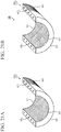
- FIG. 21A is a perspective view illustrating a first component of a first conductive member of the anti-noise component according to the third embodiment.
- FIG. 21B is a perspective view illustrating a second component of the first conductive member of the anti-noise component according to the third embodiment.
- the anti-noise component 100b according to the third embodiment will be described with reference to FIGS. 20 and 21 .
- a knurled portion 65 is provided on an inner circumferential portion of a first conductive member 6b. In this manner, a holding portion for the plug 5b is formed.
- the first conductive member 6b is constituted by a pair of components 66 1 and 66 2 having substantially semi-cylindrical shapes.
- a projecting portion (hereinafter referred to as a "first projecting portion") and a recessed portion (hereinafter referred to as a “first recessed portion”) are formed on a joining face of one component (hereinafter referred to as a "first component”) 66 1 to be joined to the other component (hereinafter referred to as a "second component”) 66 2 .
- a projecting portion (hereinafter referred to as a "second projecting portion") and a recessed portion (hereinafter referred to as a “second recessed portion”) are formed on a joining face of the second component 66 2 to be joined to the first component 66 1 .
- the first projecting portion is constituted by a plurality of projections 67i
- the second recessed portion is constituted by a plurality of holes 68 2 .
- the projections 67i are associated one-to-one with the holes 68 2 .
- each of the projections 67i can be fitted to the associated one of the holes 68 2 .
- the second projecting portion is constituted by a plurality of projections 67 2
- the first recessed portion is constituted by a plurality of holes 68 1 .
- the projections 67 2 are associated one-to-one with the holes 68 1 .
- each of the projections 672 can be fitted to the associated one of the holes 68 1 .
- the anti-noise component 100b is structured as described above.
- the user fits each of the projections 67 1 and 67 2 into the associated one of the holes 68 1 and 68 2 with the plug 5b between the components 66 1 and 66 2 , so that the components 66 1 and 66 2 are joined together.
- the plug 5b is held between the components 66 1 and 66 2 .
- the knurled portion 54 is into engagement with the knurled portion 65.
- the user screws the external thread portion 64 into the internal thread portion 73 to insert the first conductive member 6b into the second conductive member 7.
- the external thread portion 64 is in engagement with the internal thread portion 73, that is, the first conductive member 6b is inserted in the second conductive member 7.
- the user inserts the end portion 52 of the plug 5b into the end portion 31 of the jack 3. Subsequently, the user turns the first conductive member 6b relative to the jack 3. As a result, the second conductive member 7 turns integrally with the first conductive member 6b. In addition, because the knurled portion 54 is in engagement with the knurled portion 65, the plug 5b turns integrally with the first conductive member 6b.
- the user turns the second conductive member 7 relative to the first conductive member 6b.
- the turning direction in this process is opposite the turning direction of the external thread portion 64 being screwed into engagement with the internal thread portion 73.
- the second conductive member 7 moves in the axial direction. More specifically, the second conductive member 7 moves in the direction toward the metal housing 1.
- the movement of the second conductive member 7 in this direction brings the projections 75 in engagement with the outer face of the metal housing 1 and the flange portion 74 in contact or substantially in contact with the outer face of the metal housing 1 as illustrated in FIG. 25 .
- the second conductive member 7 is joined to the metal housing 1, and the second conductive member 7 is electrically connected with the metal housing 1.
- the knurled portion 65 may be provided on an inner circumferential portion of at least one of the first component 66 1 and the second component 66 2 . In addition, the knurled portion 65 may be provided on at least part of the inner circumferential portion.
- the axial length of the first conductive member 6b may be set to a value similar to that of the axial length L2 of the first conductive member 6 or may be set to a value similar to that of the axial length L2a of the first conductive member 6a, for example.
- the axial length of the first conductive member 6b may be set to a value as large as the axial length L2 or may be set a value as small as the axial length L2a.
- first projecting portion is not limited to the projections 67i.
- first projecting portion may be constituted by one projection 67i, a plurality of elongated projections, or one elongated projection.
- second recessed portion may be in any form associated with the first projecting portion, and is not limited to the holes 68 2 .
- the second recessed portion may be constituted by one hole 68 2 , a plurality of grooves, or one groove.
- the second projecting portion is not limited to the projections 67 2 .
- the second projecting portion may be constituted by one projection 67 2 , a plurality of elongated projections, or one elongated projection.
- the first recessed portion may be in any form associated with the second projecting portion, and is not limited to the holes 68 1 .
- the first recessed portion may be constituted by one hole 68 1 , a plurality of grooves, or one groove.
- the components 66 1 and 66 2 may not include the second projecting portion and the first recessed portion. In other words, the components 66 1 and 66 2 may include only the first projecting portion and the second recessed portion.
- the components 66 1 and 66 2 may not include the first projecting portion and the second recessed portion. In other words, the components 66 1 and 66 2 may include only the second projecting portion and the first recessed portion.
- first component 66 1 may have a substantially semi-cylindrical shape as mentioned above, and need not have a perfectly semi-cylindrical shape.
- second component 66 2 need may have a substantially semi-cylindrical shape as mentioned above, and need not have a perfectly semi-cylindrical shape.
- the meaning of the term "semi-cylindrical" used in the claims of the present application covers such subsequently semi-cylindrical shapes.
- the first conductive member 6 of the anti-noise component 100 may be constituted by a pair of substantially semi-cylindrical components (that is, the first component and the second component).
- the first conductive member 6 adapted to the SMA connector 200 may be constituted by the first component and the second component.
- the first conductive member 6a of the anti-noise component 100a may be constituted by a pair of substantially semi-cylindrical components (that is, the first component and the second component).
- the first conductive member 6a adapted to the SMA connector 200 may be constituted by the first component and the second component.
- anti-noise component 100b various modifications similar to those described in the first embodiment, that is, various modifications similar to those of the anti-noise component 100 can be adopted.
- anti-noise component 100b various modifications similar to those described in the second embodiment, that is, various modifications similar to those of the anti-noise component 100a can be adopted.
- the anti-noise component 100b of the third embodiment is an anti-noise component 100b for the connector 200b including the plug 5b provided on the end portion of the coaxial cable 4 and the jack 3 provided at the opening 11 of the metal housing 1 of the electronic device 300
- the anti-noise component 100b includes the cylindrical first conductive member 6b by which the plug 5b is held and the cylindrical second conductive member 7 into which the first conductive member 6b is inserted
- the holding portion for the plug 5b is formed on the inner circumferential portion of the first conductive member 6b
- the external thread portion 64 is formed on the outer circumferential portion of the first conductive member 6b
- the internal thread portion 73 is formed on the inner circumferential portion of the second conductive member 7, the external thread portion 64 can be screwed into engagement with the internal thread portion 73
- the flange portion 74 is formed at the first end 71 of the second conductive member 7, and the joining portion to be joined to the outer face of the metal housing 1 is formed on the flange portion
- the first conductive member 6b is constituted by a pair of components 66 1 and 66 2 having semi-cylindrical shapes, and the plug 5b is held between the components 66 1 and 66 2 .
- the anti-noise component 100b that complies with the N-type connector 200b, for example, can be achieved.
- FIG. 26 is an exploded perspective view of a main part of an anti-noise component according to a fourth embodiment.
- An anti-noise component 100c according to the fourth embodiment will be described with reference to FIG. 26 .
- components that are similar to those illustrated in FIGS. 3 to 5 are designated by the same reference numerals, and the description thereof will not be repeated.
- a connector 200 on which the anti-noise component 100c is to be mounted is similar to the connector 200 on which the anti-noise component 100 is to be mounted, the description thereof will not be repeated.
- a first conductive member 6c is constituted by a pair of components 66 1 ' and 66 2 ' having substantially semi-cylindrical shapes. Specifically, the first conductive member 6c is constituted by a first component 66 1 ' and a second component 66 2 '.
- the first component 66 1 ' has a first projecting portion and a first recessed portion
- the second component 66 2 ' has a second projecting portion and a second recessed portion.
- the first projecting portion is constituted by a plurality of projections 67i, for example.
- the first recessed portion is constituted by a plurality of holes 68 1 (not illustrated), for example.
- the second projecting portion is constituted by a plurality of projections 67 2 , for example.
- the second recessed portion is constituted by a plurality of holes 68 2 (not illustrated), for example.
- An inner circumferential portion of the first conductive member 6c has a shape corresponding to the shape of the plug 5. In this manner, a holding portion for the plug 5 is formed.
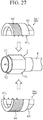
- a portion (hereinafter referred to as a "polygonal portion”) 69 having a shape corresponding to the shape of the connecting nut 51 is formed at a second end 62 of the first conductive member 6c.
- the connecting nut 51 has a hexagonal shape, and thus the polygonal portion 69 also has a hexagonal shape.
- the polygonal portion 69 has the same size as the connecting nut 51.
- the user can place a wrench on the polygonal portion 69 to turn the first conductive member 6c with the wrench.
- the user can use a typical torque wrench for SMA connectors, that is, a 5/16-inch torque wrench. As a result, turning with any torque can be achieved.
- the anti-noise component 100c is structured as described above.
- the user fits each of the projections 67 1 and 67 2 into the associated one of the holes 68 1 and 68 2 (not illustrated) with the plug 5 between the components 66 1 ' and 66 2 ', so that the components 66 1 ' and 66 2 ' are joined together.
- the plug 5 is held between the components 66 1 ' and 662'.
- the user screws the external thread portion 64 into the internal thread portion 73 to insert the first conductive member 6c into the second conductive member 7.
- the external thread portion 64 is into engagement with the internal thread portion 73, that is, the first conductive member 6c is inserted in the second conductive member 7.
- the user inserts the end portion 52 of the plug 5 into the end portion 31 of the jack 3. Subsequently, the user places a wrench on the polygonal portion 69 to turn the first conductive member 6c relative to the jack 3.
- the second conductive member 7 turns integrally with the first conductive member 6c
- the plug 5 turns integrally with the first conductive member 6c.
- the user turns the second conductive member 7 relative to the first conductive member 6c.
- the turning direction in this process is opposite the turning direction of the external thread portion 64 being screwed into engagement with the internal thread portion 73.
- the second conductive member 7 moves in the axial direction. More specifically, the second conductive member 7 moves in the direction toward the metal housing 1.
- the movement of the second conductive member 7 in this direction brings the projections 75 in engagement with the outer face of the metal housing 1 and the flange portion 74 in contact or substantially in contact with the outer face of the metal housing 1 as illustrated in FIG. 31 .
- the second conductive member 7 is joined to the metal housing 1, and the second conductive member 7 is electrically connected with the metal housing 1.
- the shape and the size of the polygonal portion 69 may be any shape and size with which the first conductive member 6c can be turned with a wrench, and are not limited to the specific example described above. As described above, however, in terms of allowing use of a typical torque wrench for SMA connectors, the shape and the size of the polygonal portion 69 are more preferably set to a shape and a size corresponding to those of the connecting nut 51.
- anti-noise component 100c various modifications similar to those described in the first embodiment, that is, various modifications similar to those of the anti-noise component 100 can be adopted.
- anti-noise component 100c various modifications similar to those described in the second embodiment, that is, various modifications similar to those of the anti-noise component 100a can be adopted.
- anti-noise component 100c various modifications similar to those described in the third embodiment, that is, various modifications similar to those of the anti-noise component 100b can be applied.
- the polygonal portion 69 for a wrench is formed at the second end 62 of the first conductive member 6c. This enables use of a wrench to turn the first conductive member 6c. As a result, a torque wrench can be used to achieve turning with any torque. In addition, this enables so-called "retightening".
- An anti-noise component of the present invention can be used for electronic devices that process RF signals, for example.
Landscapes
- Engineering & Computer Science (AREA)
- Microelectronics & Electronic Packaging (AREA)
- Coupling Device And Connection With Printed Circuit (AREA)
- Details Of Connecting Devices For Male And Female Coupling (AREA)
Abstract
Description
- The present invention relates to an anti-noise component.
- In related art, electronic devices that process high-frequency signals such as radio-frequency (RF) signals have been developed. Coaxial cables are used for transmission of RF signals.
- In related art, a structure in which an end portion of a coaxial cable is inserted in an opening of a metal housing of an electronic device, so that the coaxial cable is connected to the electronic device, has been developed. In this structure, a gap is formed between an outer circumferential portion of the end portion of the coaxial cable and an inner wall of the opening of the metal housing. This gap causes leakage of electromagnetic noise. As a result, there has been a problem of occurrence of electromagnetic noise in other electronic devices.
- In this regard,
Patent Literature 1 discloses a technology for filling the gap by using a member (hereinafter referred to as a "conductive member") made of a conductive material. This is to avoid occurrence of electromagnetic noise leakage due to the gap. - Patent Literature 1:
JP S63-55378 U - According to the technology described in
Patent Literature 1, an external conductor at an end portion of a coaxial cable is in contact with the conductive member, and the external conductor and the conductive member are thus electrically connected with each other. Specifically, as illustrated inFIG. 1 ofPatent Literature 1, a sheath at the end portion of the coaxial cable (electric cable 12) is removed, so that the external conductor (shielding layer 12a) at the end portion of the coaxial cable is exposed. In addition, the exposed external conductor is folded. Inside the metal housing (connector case 14 made of metal), the folded external conductor is in contact with an inner interferential portion of the conductive member (conductive adapter 16). - Thus, according to the technology described in
Patent Literature 1, when connecting the coaxial cable, works for removing the sheath at the end portion of the coaxial cable, works for folding the external conductor at the end portion of the coaxial cable, and the like are required. In other words, works for special processing on the end portion of the coaxial cable are required. - In addition, according to the technology described in
Patent Literature 1, the external conductor at the end portion of the thus processed coaxial cable is in contact with the conductive member in the metal housing. Thus, works for opening and closing the metal housing is required in order to electrically connect the external conductor and the conductive member with each other. - As described above, the technology described in
Patent Literature 1 has a problem in that works required in connecting the coaxial cable are troublesome. - The present invention has been made to solve such problems as mentioned above, and an object thereof is to provide an anti-noise component for which works required in connecting a coaxial cable are simplified.
- An anti-noise component of the present invention is an anti-noise component for a connector including a plug provided on an end portion of a coaxial cable and a jack provided at an opening of a metal housing of an electronic device, the anti-noise component including a first conductive member having a cylindrical shape, the plug being inserted into or held by the first conductive member, and a second conductive member having a cylindrical shape, the first conductive member being inserted into the second conductive member, wherein a holding portion for the plug is formed on an inner circumferential portion of the first conductive member, an external thread portion is formed on an outer circumferential portion of the first conductive member, an internal thread portion is formed on an inner circumferential portion of the second conductive member, the external thread portion can be screwed into engagement with the internal thread portion, a flange portion is formed at a first end of the second conductive member, and a joining portion to be joined to an outer face of the metal housing is formed on the flange portion.
- According to the present invention, the structure as described above enables an anti-noise component for which works required in connecting a coaxial cable is simplified to be achieved.
-
-
FIG. 1 is an explanatory diagram illustrating a main part of a connector on which an anti-noise component according to a first embodiment is to be mounted, in a state before a plug is connected to a jack. -
FIG. 2 is a perspective view illustrating the plug of the connector on which the anti-noise component according to the first embodiment is to be mounted. -
FIG. 3 is an exploded sectional view illustrating a main part of the anti-noise component according to the first embodiment. -
FIG. 4 is an exploded perspective view of the main part of the anti-noise component according to the first embodiment. -
FIG. 5 is another exploded perspective view of the main part of the anti-noise component according to the first embodiment. -
FIG. 6 is an explanatory diagram illustrating a state before the plug is inserted into a first conductive member. -
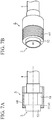
FIG. 7A is an explanatory diagram illustrating a state after the plug is inserted into the first conductive member.FIG. 7B is another explanatory diagram illustrating the state after the plug is inserted into the first conductive member. -
FIG. 8 is an explanatory diagram illustrating a state after the plug is inserted into the first conductive member and before the first conductive member is inserted into a second conductive member. -
FIG. 9A is an explanatory diagram illustrating a state after the first conductive member is inserted into the second conductive member.FIG. 9B is another explanatory diagram illustrating the state after the first conductive member is inserted into the second conductive member. -
FIG. 10 is an explanatory diagram illustrating a state after the first conductive member is inserted into the second conductive member and before the plug is connected to the jack. -
FIG. 11 is an explanatory diagram illustrating a state after the plug is connected to the jack and before the second conductive member is joined to a metal housing. -
FIG. 12 is an explanatory diagram illustrating a state after the plug is connected to the jack and after the second conductive member is joined to the metal housing. -
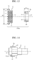
FIG. 13 is an exploded sectional view illustrating a main part of an anti-noise component according to a second embodiment. -
FIG. 14 is an explanatory diagram illustrating a state after a plug is inserted into a first conductive member. -
FIG. 15 is an explanatory diagram illustrating a state in after the first conductive member is inserted into a second conductive member. -
FIG. 16 is an explanatory diagram illustrating a state after the plug is connected to a jack and before the second conductive member is joined to a metal housing. -
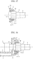
FIG. 17 is an explanatory diagram illustrating a state after the plug is connected to the jack and after the second conductive member is joined to the metal housing. -
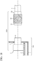
FIG. 18 is an explanatory diagram illustrating a main part of a connector on which an anti-noise component according to a third embodiment is to be mounted, in a state before a plug is connected to a jack. -
FIG. 19 is a perspective view illustrating the plug of the connector on which the anti-noise component according to the third embodiment is to be mounted. -
FIG. 20 is an exploded perspective view of a main part of the anti-noise component according to the third embodiment. -
FIG. 21A is a perspective view illustrating a first component of a first conductive member of the anti-noise component according to the third embodiment.FIG. 21B is a perspective view illustrating a second component of the first conductive member of the anti-noise component according to the third embodiment. -
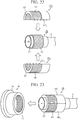
FIG. 22 is an explanatory diagram illustrating a state before the plug is held by the first conductive member. -
FIG. 23 is an explanatory diagram illustrating a state after the plug is held by the first conductive member and before the first conductive member is inserted into a second conductive member. -
FIG. 24 is an explanatory diagram illustrating a state after the plug is connected to the jack and before the second conductive member is joined to a metal housing. -
FIG. 25 is an explanatory diagram illustrating a state after the plug is connected to the jack and after the second conductive member is joined to the metal housing. -
FIG. 26 is an exploded perspective view of a main part of an anti-noise component according to a fourth embodiment. -
FIG. 27 is an explanatory diagram illustrating a state before a plug is held by a first conductive member. -
FIG. 28 is an explanatory diagram illustrating a state after the plug is held by the first conductive member and before the first conductive member is inserted into a second conductive member. -
FIG. 29 is an explanatory diagram illustrating a state after the first conductive member is inserted into the second conductive member. -
FIG. 30 is an explanatory diagram illustrating a state after the plug is connected to a jack and before the second conductive member is joined to a metal housing. -
FIG. 31 is an explanatory diagram illustrating a state after the plug is connected to the jack and after the second conductive member is joined to the metal housing. - Embodiments for carrying out the invention will now be described with reference to the accompanying drawings for more detailed explanation of the invention.
-
FIG. 1 is an explanatory diagram illustrating a main part of a connector on which an anti-noise component according to a first embodiment is to be mounted, in a state before a plug is connected to a jack.FIG. 2 is a perspective view illustrating the plug of the connector on which the anti-noise component according to the first embodiment is to be mounted. Aconnector 200 on which ananti-noise component 100 according to the first embodiment is to be mounted will be described with reference toFIGS. 1 and2 . - In
FIG. 1 , areference numeral 1 represents a metal housing. Acircuit board 2 is provided in themetal housing 1, and ajack 3 is mounted on thecircuit board 2. Thejack 3 is inserted in anopening 11 of themetal housing 1. Anend portion 31 of thejack 3 thus protrudes out of themetal housing 1. - The
metal housing 1, thecircuit board 2, and thejack 3 constitute a main part of a main unit of anelectronic device 300. Theelectronic device 300 processes high-frequency signals. More specifically, theelectronic device 300 processes RF signals. Acoaxial cable 4 is used to input RF signals to theelectronic device 300 or to output RF signals by theelectronic device 300. - A
plug 5 is provided on the end portion of thecoaxial cable 4. Thejack 3 and theplug 5 constitute a main part of theconnector 200. In the example illustrated inFIGS. 1 and2 , theconnector 200 is a Sub Miniature Type A (SMA) connector. Thus, theplug 5 includes a hexagonal connectingnut 51. In addition, anend portion 52 of theplug 5 protrudes from the connectingnut 51. A steppedportion 53 is thus formed between the connectingnut 51 and theend portion 52. - In
FIG. 1 , L1 represents a dimension of the connectingnut 51 in the axial direction (hereinafter referred to as an "axial length"). In addition, D1 represents a dimension of the opening 11 (hereinafter referred to as an "opening diameter". -
FIG. 3 is an exploded sectional view illustrating a main part of the anti-noise component according to the first embodiment.FIG. 4 is an exploded perspective view of the main part of the anti-noise component according to the first embodiment.FIG. 5 is another exploded perspective view of the main part of the anti-noise component according to the first embodiment. Theanti-noise component 100 according to the first embodiment will be described with reference toFIGS. 3 to 5 . - As illustrated in
FIGS. 3 to 5 , theanti-noise component 100 is constituted by a pair ofconductive members conductive member 6 of the pair ofconductive members conductive member 7 will be referred to as a "second conductive member". In addition, oneend 61 of theends conductive member 6 will be referred to as a "first end", and theother end 62 will be referred to as a "second end". In addition, oneend 71 of theends conductive member 7 will be referred to as a "first end", and theother end 72 will be referred to as a "second end". Thus, thefirst end 61 is an end on the same side as thefirst end 71, and thesecond end 62 is an end on the same side as thesecond end 72. - The
plug 5 is inserted into the firstconductive member 6. A holding portion for theplug 5 is formed on the inner circumferential portion of the firstconductive member 6. - Specifically, the inner circumferential portion of the first
conductive member 6 has a shape corresponding to the shape of the connectingnut 51. In the example illustrated inFIGS. 3 to 5 , because the connectingnut 51 has a hexagonal shape, the inner circumferential portion of the firstconductive member 6 also has a hexagonal shape. In addition, a stepped portion (hereinafter referred to as a "stopper portion") 63 corresponding to the steppedportion 53 is formed at the inner circumferential portion of the firstconductive member 6. - When the
plug 5 is inserted into the firstconductive member 6 through thesecond end 62, the outer circumferential portion of the connectingnut 51 comes in contact with the inner circumferential portion of the firstconductive member 6, and the steppedportion 53 comes in contact with thestopper portion 63. In this manner, theplug 5 is fitted into the firstconductive member 6. As a result, theplug 5 is held by the firstconductive member 6. In addition, in this state, theend portion 52 of theplug 5 protrudes out of the firstconductive member 6 through thefirst end 61. - The holding portion for the
plug 5 is formed in this manner. - The first
conductive member 6 is inserted into the secondconductive member 7. Specifically, anexternal thread portion 64 is formed on an outer circumferential portion of the firstconductive member 6, and aninternal thread portion 73 on an inner circumferential portion of the secondconductive member 7. Theexternal thread portion 64 can be screwed into engagement with theinternal thread portion 73. - In
FIG. 3 , L2 represents the axial length of the firstconductive member 6. The axial length L2 of the firstconductive member 6 is set to a value larger than the axial length L1 of the connecting nut 51 (seeFIG. 1 ). Thus, when theplug 5 is inserted into the firstconductive member 6, the whole or substantially the whole of the connectingnut 51 is located inside the firstconductive member 6. In addition, theexternal thread portion 64 is formed on substantially a half, on thefirst end 61 side, of the outer circumferential portion of the firstconductive member 6. - In addition, a
flange portion 74 is formed at thefirst end 71 of the secondconductive member 7. A joining portion to be joined to an outer face of themetal housing 1 is formed on theflange portion 74. - Specifically, in the example illustrated in
FIGS. 3 to 5 , theflange portion 74 has a substantially disc-like shape, and a plurality ofprojections 75 is formed on theflange portion 74. InFIG. 3 , D2 represents the diameter of theflange portion 74. The diameter D2 of theflange portion 74 is set to a value larger than the opening diameter D1 of the opening 11 (seeFIG. 1 ). The joining portion to be joined to the outer face of themetal housing 1 is thus formed. - Next, a method for connecting the
coaxial cable 4 to theelectronic device 300 and mounting theanti-noise component 100 onto theconnector 200 will be explained with reference toFIGS. 6 to 12 . - First, as illustrated in
FIG. 6 , a user inserts theplug 5 into the firstconductive member 6 through thesecond end 62. As a result, as illustrated inFIG. 7 , theplug 5 is in a state of being inserted in the firstconductive member 6. - At this point, because the inner circumferential portion of the first
conductive member 6 has a hexagonal shape, the outer circumferential portion of the connectingnut 51 is in contact with the inner circumferential portion of the firstconductive member 6. In addition, the steppedportion 53 is in contact with thestopper portion 63. In other words, theplug 5 is fitted into the firstconductive member 6. In this manner, theplug 5 is held in the firstconductive member 6. - Subsequently, as illustrated in
FIG. 8 , the user screws theexternal thread portion 64 into theinternal thread portion 73 to insert the firstconductive member 6 into the secondconductive member 7. As a result, as illustrated inFIG. 9 , theexternal thread portion 64 is in engagement with theinternal thread portion 73, that is, the firstconductive member 6 is inserted in the secondconductive member 7. - Subsequently, as illustrated in
FIG. 10 , the user inserts theend portion 52 of theplug 5 into theend portion 31 of thejack 3. Subsequently, the user turns the firstconductive member 6 relative to thejack 3. As a result, the secondconductive member 7 turns integrally with the firstconductive member 6. In addition, as the connectingnut 51 turns integrally with the firstconductive member 6, theplug 5 turns integrally with the firstconductive member 6. - The turning of the
plug 5 relative to thejack 3 screws an external thread portion (not illustrated) formed on an outer circumferential portion of theend portion 31 of thejack 3 into engagement with an internal thread portion (not illustrated) formed on an inner circumferential portion of theend portion 52 of theplug 5. As a result, as illustrated inFIG. 11 , theplug 5 is connected with thejack 3. - Subsequently, the user turns the second
conductive member 7 relative to the firstconductive member 6. The turning direction in this process is opposite the turning direction of theexternal thread portion 64 being screwed into engagement with theinternal thread portion 73. As a result, the secondconductive member 7 moves in the axial direction. More specifically, the secondconductive member 7 moves in the direction toward themetal housing 1. - The movement of the second
conductive member 7 in this direction brings theprojections 75 in engagement with the outer face of themetal housing 1 and theflange portion 74 in contact or substantially in contact with the outer face of themetal housing 1 as illustrated inFIGs. 11 and 12 . Thus, the secondconductive member 7 is joined to themetal housing 1, and the secondconductive member 7 is electrically connected with themetal housing 1. - As a result, the connection of the
coaxial cable 4 to theelectronic device 300 is completed, and the mounting of theanti-noise component 100 onto theconnector 200 is completed. - Next, effects of the
anti-noise component 100 will be explained. - Typically, the
plug 5 is made of metal, and electrically connected with an external conductor (not illustrated) of thecoaxial cable 4. In the state in which the mounting of theanti-noise component 100 onto theconnector 200 is completed, themetal housing 1, theplug 5, the firstconductive member 6, and the secondconductive member 7 are electrically connected with each other. In this manner, occurrence of electromagnetic noise leakage through theopening 11 can be avoided. As a result, occurrence of electromagnetic noise on other electronic devices can be reduced. - In addition, the
anti-noise component 100 complies with thecoaxial cable 4 with theplug 5. Thus, no special processing is needed on an end portion of thecoaxial cable 4 when connecting thecoaxial cable 4 to theelectronic device 300. In addition, because the processing is not needed on RF signal transmission lines, the quality of transmission of RF signals can be improved. - In addition, the
anti-noise component 100 is to be electrically connected with the external conductor (more specifically, the plug 5) of thecoaxial cable 4 outside of themetal housing 1, and to be electrically connected with themetal housing 1 outside of themetal housing 1. This eliminates the need for works inside themetal housing 1 when theanti-noise component 100 is mounted onto theconnector 200. Thus, themetal housing 1 need not be opened and closed when theanti-noise component 100 is mounted onto theconnector 200. - Next, modifications of the
anti-noise component 100 and theconnector 200 will be described. - First, the
connector 200 is not limited to an SMA connector, but may be of any type. For example, theconnector 200 may be an N-type connector. Thus, instead of the connectingnut 51 provided on theplug 5, knurling may be performed on an outer circumferential portion of theplug 5. - In addition, the holding portion for the
plug 5 at the inner circumferential portion of the firstconductive member 6 may be in any form adapted to the type of theconnector 200 and is not limited to the specific examples mentioned above. For example, in the case where theconnector 200 is an N-type connector, the holing portion for theplug 5 may be formed by knurling the inner circumferential portion of the firstconductive member 6. Specifically, theplug 5 may be held by the firstconductive member 6 in such a manner that the knurled portion at the outer circumferential portion of theplug 5 and the knurled portion at the inner circumferential portion of the firstconductive member 6 are in engagement with each other. - In addition, the joining portion of the
flange portion 74 to be joined to the outer face of themetal housing 1 may have any shape that enables the joining, and is not limited to the specific example mentioned above. For example, the joining portion may be formed in such a manner that theflange portion 74 has a substantially disc-like shape and that oneprojection 75 is formed on theflange portion 74. Alternatively, for example, the joining portion may be formed in such a manner that theflange portion 74 has a shape of a tooth lock washer. - In addition, the shape of the first
conductive member 6 may have a substantially cylindrical shape as mentioned above, and need not have a perfectly cylindrical shape. In addition, the shape of the secondconductive member 7 may have a substantially cylindrical shape having theflange portion 74 as described above, and need not have a perfectly cylindrical shape. The meaning of the term "cylindrical" used in the claims of the present application covers such subsequently cylindrical shapes. - As described above, the
anti-noise component 100 of the first embodiment is ananti-noise component 100 for theconnector 200 including theplug 5 provided on the end portion of thecoaxial cable 4 and thejack 3 provided at theopening 11 of themetal housing 1 of theelectronic device 300, theanti-noise component 100 includes the cylindrical firstconductive member 6 into which theplug 5 is inserted and the cylindrical secondconductive member 7 into which the firstconductive member 6 is inserted, the holding portion for theplug 5 is formed on the inner circumferential portion of the firstconductive member 6, theexternal thread portion 64 is formed on the outer circumferential portion of the firstconductive member 6, theinternal thread portion 73 is formed on the inner circumferential portion of the secondconductive member 7, theexternal thread portion 64 can be screwed into engagement with theinternal thread portion 73, theflange portion 74 is formed at thefirst end 71 of the secondconductive member 7, and the joining portion to be joined to the outer face of themetal housing 1 is formed on theflange portion 74. In this manner, occurrence of electromagnetic noise leakage through theopening 11 can be avoided. As a result, occurrence of electromagnetic noise on other electronic devices can be reduced. In addition, the need for works for applying special processing on the end portion of thecoaxial cable 4, works for opening and closing themetal housing 1, and the like in connecting thecoaxial cable 4 to theelectronic device 300, that is, in mounting theanti-noise component 100 onto theconnector 200 can be eliminated. Consequently, works required in connecting thecoaxial cable 4, that is, in mounting theanti-noise component 100 can be simplified. -
FIG. 13 is an exploded sectional view illustrating a main part of an anti-noise component according to a second embodiment. Ananti-noise component 100a according to the second embodiment will be described with reference toFIG. 13 . Note that, inFIG. 13 , components that are similar to those illustrated inFIGS. 3 to 5 are designated by the same reference numerals, and the description thereof will not be repeated. In addition, because theconnector 200 on which theanti-noise component 100a is to be mounted is similar to theconnector 200 on which theanti-noise component 100 is to be mounted, the description thereof will not be repeated. - As illustrated in
FIG. 13 , theanti-noise component 100a is constituted by a firstconductive member 6a and the secondconductive member 7. In theanti-noise component 100a, the axial length L2a of the firstconductive member 6a differs from the axial length L2 of the first conductive member 6 (seeFIG. 3 ). - Specifically, the axial length L2a of the first
conductive member 6a is set to a value smaller than the axial length L1 of the connecting nut 51 (seeFIG. 1 ). Specifically, for example, the axial length L2a of the firstconductive member 6a is set to a value that is substantially a half of the axial length L1 of the connectingnut 51. Thus, when theplug 5 is inserted into the firstconductive member 6 through thesecond end 62, substantially a half (hereinafter referred to as a "first half part") of the connectingnut 51 is located inside the firstconductive member 6 and the remaining substantial half (hereinafter referred to as a "second half part") of the connectingnut 51 protrudes out of the firstconductive member 6 through thesecond end 62. In addition, theexternal thread portion 64 is formed on the whole or substantially the whole of the outer circumferential portion of the firstconductive member 6. - Next, a method for connecting the
coaxial cable 4 to theelectronic device 300 and mounting theanti-noise component 100a onto theconnector 200 will be explained with reference toFIGS. 14 to 17 . - First, the user inserts the
plug 5 into the firstconductive member 6a through thesecond end 62. As a result, as illustrated inFIG. 14 , the plug is inserted in the firstconductive member 6a. At this point, as described above, the first half part of connectingnut 51 is located inside the firstconductive member 6a, and the second half part of the connectingnut 51 protrudes out of the firstconductive member 6a through thesecond end 62. - Subsequently, the user screws the
external thread portion 64 into theinternal thread portion 73 to insert the firstconductive member 6a into the secondconductive member 7. As a result, as illustrated inFIG. 15 , theexternal thread portion 64 is into engagement with theinternal thread portion 73, that is, the firstconductive member 6a is inserted in the secondconductive member 7. - Subsequently, the user inserts the
end portion 52 of theplug 5 into theend portion 31 of thejack 3. Subsequently, the user places a torque wrench on the second half part of the connectingnut 51 to turn the connectingnut 51 relative to thejack 3. As a result, theplug 5, the firstconductive member 6, and the secondconductive member 7 turn integrally with each other. Use of the torque wrench enables these members to be turned with any torque. - The turning of the
plug 5 relative to thejack 3 screws an external thread portion (not illustrated) formed on an outer circumferential portion of theend portion 31 of thejack 3 into engagement with an internal thread portion (not illustrated) formed on an inner circumferential portion of theend portion 52 of theplug 5. As a result, as illustrated inFIG. 16 , theplug 5 is connected with thejack 3. - Subsequently, the user turns the second
conductive member 7 relative to theplug 5 and the firstconductive member 6a. The turning direction in this process is opposite the turning direction of theexternal thread portion 64 being screwed into engagement with theinternal thread portion 73. As a result, the secondconductive member 7 moves in the axial direction. More specifically, the secondconductive member 7 moves in the direction toward themetal housing 1. - The movement of the second
conductive member 7 in this direction brings theprojections 75 in engagement with the outer face of themetal housing 1 and theflange portion 74 in contact or substantially in contact with the outer face of themetal housing 1 as illustrated inFIGs. 16 and17 . Thus, the secondconductive member 7 is joined to themetal housing 1, and the secondconductive member 7 is electrically connected with themetal housing 1. - As a result, the connection of the
coaxial cable 4 to theelectronic device 300 is completed, and the mounting of theanti-noise component 100a onto theconnector 200 is completed. - Note that the axial length L2a of the first
conductive member 6a may be any value smaller than the axial length L1 of the connectingnut 51, and is not limited to the value that is substantially a half of the axial length L1 of the connectingnut 51. The axial length L2a of the firstconductive member 6a is, however, preferably set to a suitable value in terms of making the amount by which the connectingnut 51 protrudes from the firstconductive member 6a be sufficiently large to enable placement of the torque wrench. - In addition, for the
anti-noise component 100a, various modifications similar to those described in the first embodiment, that is, various modifications similar to those of theanti-noise component 100 can be adopted. - As described above, in the
anti-noise component 100a of the second embodiment, theconnector 200 is of a type in which theplug 5 includes the connectingnut 51, and the axial length L2a of the firstconductive member 6a is set to a value smaller than the axial length L1 of the connectingnut 51. This enables use of a torque wrench to turn theplug 5. As a result, turning with any torque can be achieved. -
FIG. 18 is an explanatory diagram illustrating a main part of a connector on which an anti-noise component according to a third embodiment is to be mounted, in a state before a plug is connected to a jack.FIG. 19 is a perspective view illustrating the plug of the connector on which the anti-noise component according to the third embodiment is to be mounted. Aconnector 200b on which ananti-noise component 100b according to the third embodiment is to be mounted will be described with reference toFIGS. 18 and19 . Note that, inFIGS. 18 and19 , components that are similar to those illustrated inFIGS. 1 and2 are designated by the same reference numerals, and the description thereof will not be repeated. - As illustrated in
FIGS. 18 and19 , theconnector 200b is an N-type connector. Thus, aknurled portion 54 is provided on an outer circumferential portion of aplug 5b. -
FIG. 20 is an exploded perspective view of a main part of the anti-noise component according to the third embodiment.FIG. 21A is a perspective view illustrating a first component of a first conductive member of the anti-noise component according to the third embodiment.FIG. 21B is a perspective view illustrating a second component of the first conductive member of the anti-noise component according to the third embodiment. Theanti-noise component 100b according to the third embodiment will be described with reference toFIGS. 20 and21 . - As illustrated in
FIGS. 20 and21 , aknurled portion 65 is provided on an inner circumferential portion of a firstconductive member 6b. In this manner, a holding portion for theplug 5b is formed. - In addition, the first
conductive member 6b is constituted by a pair of components 661 and 662 having substantially semi-cylindrical shapes. A projecting portion (hereinafter referred to as a "first projecting portion") and a recessed portion (hereinafter referred to as a "first recessed portion") are formed on a joining face of one component (hereinafter referred to as a "first component") 661 to be joined to the other component (hereinafter referred to as a "second component") 662. Similarly, a projecting portion (hereinafter referred to as a "second projecting portion") and a recessed portion (hereinafter referred to as a "second recessed portion") are formed on a joining face of the second component 662 to be joined to the first component 661. - In the example illustrated in
FIGS. 20 and21 , the first projecting portion is constituted by a plurality of projections 67i, and the second recessed portion is constituted by a plurality of holes 682. The projections 67i are associated one-to-one with the holes 682. Thus, each of the projections 67i can be fitted to the associated one of the holes 682. - Similarly, in the example illustrated in
FIGS. 20 and21 , the second projecting portion is constituted by a plurality of projections 672, and the first recessed portion is constituted by a plurality of holes 681. The projections 672 are associated one-to-one with the holes 681. Thus, each of theprojections 672 can be fitted to the associated one of the holes 681. - The
anti-noise component 100b is structured as described above. - Next, a method for connecting the
coaxial cable 4 to theelectronic device 300 and mounting theanti-noise component 100b onto theconnector 200b will be explained with reference toFIGS. 22 to 25 . - First, as illustrated in
FIG. 22 , the user fits each of the projections 671 and 672 into the associated one of the holes 681 and 682 with theplug 5b between the components 661 and 662, so that the components 661 and 662 are joined together. As a result, as illustrated inFIG. 23 , theplug 5b is held between the components 661 and 662. In other words, theknurled portion 54 is into engagement with theknurled portion 65. - Subsequently, as illustrated in
FIG. 23 , the user screws theexternal thread portion 64 into theinternal thread portion 73 to insert the firstconductive member 6b into the secondconductive member 7. As a result, as illustrated inFIG. 24 , theexternal thread portion 64 is in engagement with theinternal thread portion 73, that is, the firstconductive member 6b is inserted in the secondconductive member 7. - Subsequently, the user inserts the
end portion 52 of theplug 5b into theend portion 31 of thejack 3. Subsequently, the user turns the firstconductive member 6b relative to thejack 3. As a result, the secondconductive member 7 turns integrally with the firstconductive member 6b. In addition, because theknurled portion 54 is in engagement with theknurled portion 65, theplug 5b turns integrally with the firstconductive member 6b. - The turning of the
plug 5b relative to thejack 3 screws an external thread portion (not illustrated) formed on an outer circumferential portion of theend portion 31 of thejack 3 into engagement with an internal thread portion (not illustrated) formed on an inner circumferential portion of theend portion 52 of theplug 5b. As a result, as illustrated inFIG. 24 , theplug 5b is connected with thejack 3. - Subsequently, as illustrated in
FIG. 24 , the user turns the secondconductive member 7 relative to the firstconductive member 6b. The turning direction in this process is opposite the turning direction of theexternal thread portion 64 being screwed into engagement with theinternal thread portion 73. As a result, the secondconductive member 7 moves in the axial direction. More specifically, the secondconductive member 7 moves in the direction toward themetal housing 1. - The movement of the second
conductive member 7 in this direction brings theprojections 75 in engagement with the outer face of themetal housing 1 and theflange portion 74 in contact or substantially in contact with the outer face of themetal housing 1 as illustrated inFIG. 25 . Thus, the secondconductive member 7 is joined to themetal housing 1, and the secondconductive member 7 is electrically connected with themetal housing 1. - As a result, the connection of the
coaxial cable 4 to theelectronic device 300 is completed, and the mounting of theanti-noise component 100b onto theconnector 200b is completed. - Note that the
knurled portion 65 may be provided on an inner circumferential portion of at least one of the first component 661 and the second component 662. In addition, theknurled portion 65 may be provided on at least part of the inner circumferential portion. - In addition, the axial length of the first
conductive member 6b may be set to a value similar to that of the axial length L2 of the firstconductive member 6 or may be set to a value similar to that of the axial length L2a of the firstconductive member 6a, for example. In other words, the axial length of the firstconductive member 6b may be set to a value as large as the axial length L2 or may be set a value as small as the axial length L2a. - In addition, the first projecting portion is not limited to the projections 67i. For example, the first projecting portion may be constituted by one projection 67i, a plurality of elongated projections, or one elongated projection. In addition, the second recessed portion may be in any form associated with the first projecting portion, and is not limited to the holes 682. For example, the second recessed portion may be constituted by one hole 682, a plurality of grooves, or one groove.
- In addition, the second projecting portion is not limited to the projections 672. For example, the second projecting portion may be constituted by one projection 672, a plurality of elongated projections, or one elongated projection. In addition, the first recessed portion may be in any form associated with the second projecting portion, and is not limited to the holes 681. For example, the first recessed portion may be constituted by one hole 681, a plurality of grooves, or one groove.
- In addition, the components 661 and 662 may not include the second projecting portion and the first recessed portion. In other words, the components 661 and 662 may include only the first projecting portion and the second recessed portion.
- In addition, the components 661 and 662 may not include the first projecting portion and the second recessed portion. In other words, the components 661 and 662 may include only the second projecting portion and the first recessed portion.
- In addition, the first component 661 may have a substantially semi-cylindrical shape as mentioned above, and need not have a perfectly semi-cylindrical shape. In addition, the second component 662 need may have a substantially semi-cylindrical shape as mentioned above, and need not have a perfectly semi-cylindrical shape. The meaning of the term "semi-cylindrical" used in the claims of the present application covers such subsequently semi-cylindrical shapes.
- In addition, in a manner similar to the first
conductive member 6b of theanti-noise component 100b, the firstconductive member 6 of theanti-noise component 100 may be constituted by a pair of substantially semi-cylindrical components (that is, the first component and the second component). Specifically, the firstconductive member 6 adapted to theSMA connector 200 may be constituted by the first component and the second component. - In addition, in a manner similar to the first
conductive member 6b of theanti-noise component 100b, the firstconductive member 6a of theanti-noise component 100a may be constituted by a pair of substantially semi-cylindrical components (that is, the first component and the second component). Specifically, the firstconductive member 6a adapted to theSMA connector 200 may be constituted by the first component and the second component. - Additionally, for the
anti-noise component 100b, various modifications similar to those described in the first embodiment, that is, various modifications similar to those of theanti-noise component 100 can be adopted. In addition, for theanti-noise component 100b, various modifications similar to those described in the second embodiment, that is, various modifications similar to those of theanti-noise component 100a can be adopted. - As described above, the
anti-noise component 100b of the third embodiment is ananti-noise component 100b for theconnector 200b including theplug 5b provided on the end portion of thecoaxial cable 4 and thejack 3 provided at theopening 11 of themetal housing 1 of theelectronic device 300, theanti-noise component 100b includes the cylindrical firstconductive member 6b by which theplug 5b is held and the cylindrical secondconductive member 7 into which the firstconductive member 6b is inserted, the holding portion for theplug 5b is formed on the inner circumferential portion of the firstconductive member 6b, theexternal thread portion 64 is formed on the outer circumferential portion of the firstconductive member 6b, theinternal thread portion 73 is formed on the inner circumferential portion of the secondconductive member 7, theexternal thread portion 64 can be screwed into engagement with theinternal thread portion 73, theflange portion 74 is formed at thefirst end 71 of the secondconductive member 7, and the joining portion to be joined to the outer face of themetal housing 1 is formed on theflange portion 74. In this manner, occurrence of electromagnetic noise leakage through theopening 11 can be avoided. As a result, occurrence of electromagnetic noise on other electronic devices can be reduced. In addition, the need for works for applying special processing on the end portion of thecoaxial cable 4, works for opening and closing themetal housing 1, and the like in connecting thecoaxial cable 4 to theelectronic device 300, that is, in mounting theanti-noise component 100b onto theconnector 200b can be eliminated. Consequently, works required in connecting thecoaxial cable 4, that is, in mounting theanti-noise component 100b can be simplified. - In addition, in the
anti-noise component 100b of the third embodiment, the firstconductive member 6b is constituted by a pair of components 661 and 662 having semi-cylindrical shapes, and theplug 5b is held between the components 661 and 662. As a result, theanti-noise component 100b that complies with the N-type connector 200b, for example, can be achieved. -
FIG. 26 is an exploded perspective view of a main part of an anti-noise component according to a fourth embodiment. Ananti-noise component 100c according to the fourth embodiment will be described with reference toFIG. 26 . Note that, inFIG. 26 , components that are similar to those illustrated inFIGS. 3 to 5 are designated by the same reference numerals, and the description thereof will not be repeated. In addition, because aconnector 200 on which theanti-noise component 100c is to be mounted is similar to theconnector 200 on which theanti-noise component 100 is to be mounted, the description thereof will not be repeated. - As illustrated in
FIG. 26 , a firstconductive member 6c is constituted by a pair of components 661' and 662' having substantially semi-cylindrical shapes.
Specifically, the firstconductive member 6c is constituted by a first component 661' and a second component 662'. - The first component 661' has a first projecting portion and a first recessed portion, and the second component 662' has a second projecting portion and a second recessed portion. The first projecting portion is constituted by a plurality of projections 67i, for example. The first recessed portion is constituted by a plurality of holes 681 (not illustrated), for example. The second projecting portion is constituted by a plurality of projections 672, for example. The second recessed portion is constituted by a plurality of holes 682 (not illustrated), for example.
- An inner circumferential portion of the first
conductive member 6c has a shape corresponding to the shape of theplug 5. In this manner, a holding portion for theplug 5 is formed. - Note that a portion (hereinafter referred to as a "polygonal portion") 69 having a shape corresponding to the shape of the connecting
nut 51 is formed at asecond end 62 of the firstconductive member 6c. In the example illustrated inFIG. 26 , the connectingnut 51 has a hexagonal shape, and thus thepolygonal portion 69 also has a hexagonal shape. In addition, thepolygonal portion 69 has the same size as the connectingnut 51. - Thus, for turning the first
conductive member 6c, the user can place a wrench on thepolygonal portion 69 to turn the firstconductive member 6c with the wrench. - In this process, the user can use a typical torque wrench for SMA connectors, that is, a 5/16-inch torque wrench. As a result, turning with any torque can be achieved.
- The
anti-noise component 100c is structured as described above. - Next, a method for connecting the
coaxial cable 4 to theelectronic device 300 and mounting theanti-noise component 100c onto theconnector 200 will be explained with reference toFIGS. 27 to 31 . - First, as illustrated in
FIG. 27 , the user fits each of the projections 671 and 672 into the associated one of the holes 681 and 682 (not illustrated) with theplug 5 between the components 661' and 662', so that the components 661' and 662' are joined together. As a result, as illustrated inFIG. 28 , theplug 5 is held between the components 661' and 662'. - Subsequently, as illustrated in
FIG. 28 , the user screws theexternal thread portion 64 into theinternal thread portion 73 to insert the firstconductive member 6c into the secondconductive member 7. As a result, as illustrated inFIG. 29 , theexternal thread portion 64 is into engagement with theinternal thread portion 73, that is, the firstconductive member 6c is inserted in the secondconductive member 7. - Subsequently, the user inserts the
end portion 52 of theplug 5 into theend portion 31 of thejack 3. Subsequently, the user places a wrench on thepolygonal portion 69 to turn the firstconductive member 6c relative to thejack 3. Thus, the secondconductive member 7 turns integrally with the firstconductive member 6c, and theplug 5 turns integrally with the firstconductive member 6c. - The turning of the
plug 5 relative to thejack 3 screws an external thread portion (not illustrated) formed on an outer circumferential portion of theend portion 31 of thejack 3 into engagement with an internal thread portion (not illustrated) formed on an inner circumferential portion of theend portion 52 of theplug 5. As a result, as illustrated inFIG. 30 , theplug 5 is connected with thejack 3. - Subsequently, as illustrated in
FIG. 30 , the user turns the secondconductive member 7 relative to the firstconductive member 6c. The turning direction in this process is opposite the turning direction of theexternal thread portion 64 being screwed into engagement with theinternal thread portion 73. As a result, the secondconductive member 7 moves in the axial direction. More specifically, the secondconductive member 7 moves in the direction toward themetal housing 1. - The movement of the second
conductive member 7 in this direction brings theprojections 75 in engagement with the outer face of themetal housing 1 and theflange portion 74 in contact or substantially in contact with the outer face of themetal housing 1 as illustrated inFIG. 31 . Thus, the secondconductive member 7 is joined to themetal housing 1, and the secondconductive member 7 is electrically connected with themetal housing 1. - As a result, the connection of the
coaxial cable 4 to theelectronic device 300 is completed, and the mounting of theanti-noise component 100c onto theconnector 200 is completed. - Note that the shape and the size of the
polygonal portion 69 may be any shape and size with which the firstconductive member 6c can be turned with a wrench, and are not limited to the specific example described above. As described above, however, in terms of allowing use of a typical torque wrench for SMA connectors, the shape and the size of thepolygonal portion 69 are more preferably set to a shape and a size corresponding to those of the connectingnut 51. - Additionally, for the
anti-noise component 100c, various modifications similar to those described in the first embodiment, that is, various modifications similar to those of theanti-noise component 100 can be adopted. In addition, for theanti-noise component 100c, various modifications similar to those described in the second embodiment, that is, various modifications similar to those of theanti-noise component 100a can be adopted. In addition, for theanti-noise component 100c, various modifications similar to those described in the third embodiment, that is, various modifications similar to those of theanti-noise component 100b can be applied. - As described above, according to the
anti-noise component 100c of the fourth embodiment, thepolygonal portion 69 for a wrench is formed at thesecond end 62 of the firstconductive member 6c. This enables use of a wrench to turn the firstconductive member 6c. As a result, a torque wrench can be used to achieve turning with any torque. In addition, this enables so-called "retightening". - Note that the embodiments of the present invention can be freely combined, any components in the embodiments can be modified, and any components in the embodiments can be omitted within the scope of the invention of the present application.
- An anti-noise component of the present invention can be used for electronic devices that process RF signals, for example.
- 1: metal housing, 2: circuit board, 3: jack, 4: coaxial cable, 5, 5b: plug, 6, 6a, 6b, 6c: conductive member (first conductive member), 7: conductive member (second conductive member), 11: opening, 31: end portion, 51: connecting nut, 52: end portion, 53: stepped portion, 54: knurled portion, 61: end (first end), 62: end (second end), 63: stopper portion, 64: external thread portion, 65: knurled portion, 661: component (first component), 661': component (first component), 662: component (second component), 662': component (second component), 67i: projection, 672: projection, 681: hole, 682: hole, 69: polygonal portion, 71: end (first end), 72: end (second end), 73: internal thread portion, 74: flange portion, 75: projection, 100, 100a, 100b, 100c: anti-noise component, 200, 200b: connector, 300: electronic device
Claims (4)
- An anti-noise component for a connector including a plug provided on an end portion of a coaxial cable, and a jack provided at an opening of a metal housing of an electronic device, the anti-noise component comprising:a first conductive member having a cylindrical shape, the plug being inserted into or held by the first conductive member, and a second conductive member having a cylindrical shape, the first conductive member being inserted into the second conductive member, whereina holding portion for the plug is formed on an inner circumferential portion of the first conductive member,an external thread portion is formed on an outer circumferential portion of the first conductive member, an internal thread portion is formed on an inner circumferential portion of the second conductive member, and the external thread portion can be screwed into engagement with the internal thread portion, anda flange portion is formed at a first end of the second conductive member, and a joining portion to be joined to an outer face of the metal housing is formed on the flange portion.
- The anti-noise component according to claim 1, whereinthe connector is of a type with the plug including a connecting nut, andthe first conductive member has an axial length set to a value smaller than an axial length of the connecting nut.
- The anti-noise component according to claim 1, wherein the first conductive member is constituted by a pair of components having semi-cylindrical shapes, and the plug is held between the components.
- The anti-noise component according to claim 1, wherein a polygonal portion for a wrench is formed at a second end of the first conductive member.
Applications Claiming Priority (1)
| Application Number | Priority Date | Filing Date | Title |
|---|---|---|---|
| PCT/JP2018/046807 WO2020129188A1 (en) | 2018-12-19 | 2018-12-19 | Anti-noise component |
Publications (3)
| Publication Number | Publication Date |
|---|---|
| EP3886272A1 true EP3886272A1 (en) | 2021-09-29 |
| EP3886272A4 EP3886272A4 (en) | 2021-12-01 |
| EP3886272B1 EP3886272B1 (en) | 2024-02-28 |
Family
ID=71101156
Family Applications (1)
| Application Number | Title | Priority Date | Filing Date |
|---|---|---|---|
| EP18943393.1A Active EP3886272B1 (en) | 2018-12-19 | 2018-12-19 | Anti-noise component |
Country Status (4)
| Country | Link |
|---|---|
| US (1) | US11735869B2 (en) |
| EP (1) | EP3886272B1 (en) |
| JP (1) | JP6833141B2 (en) |
| WO (1) | WO2020129188A1 (en) |
Families Citing this family (1)
| Publication number | Priority date | Publication date | Assignee | Title |
|---|---|---|---|---|
| WO2022264392A1 (en) * | 2021-06-18 | 2022-12-22 | 三菱電機株式会社 | Connector panel |
Family Cites Families (13)
| Publication number | Priority date | Publication date | Assignee | Title |
|---|---|---|---|---|
| US3104120A (en) * | 1958-12-01 | 1963-09-17 | Ahlport Brodie | Coupling for conduits |
| JPS6355378U (en) | 1986-09-29 | 1988-04-13 | ||
| US4822293A (en) * | 1987-11-20 | 1989-04-18 | General Dynamics, Pomona Division | Bell housing sealing assembly for mounted connector |
| US6250960B1 (en) * | 2000-07-12 | 2001-06-26 | Pct International, Inc. | Female to female CATV splice connector |
| US20100199813A1 (en) * | 2009-02-11 | 2010-08-12 | Neil Patrick Phillips | Torque Wrenches for Coaxial Patch Cords and Related Assemblies and Methods |
| JP5494927B2 (en) * | 2009-08-03 | 2014-05-21 | 株式会社リコー | Camera unit and sensing device |
| US8430687B2 (en) * | 2011-04-01 | 2013-04-30 | Ppc Broadband, Inc. | Method and apparatus for a snap retained push-on connector with port adapter |
| WO2013089160A1 (en) * | 2011-12-13 | 2013-06-20 | 矢崎総業株式会社 | Structure for fixing electrical connection section, connector, and method for connecting connector |
| JP6059454B2 (en) * | 2012-06-22 | 2017-01-11 | 株式会社キーエンス | Liquid level measuring device |
| EP2944969B1 (en) * | 2013-01-08 | 2020-12-30 | Mitsubishi Electric Corporation | Antenna and cable connection status verification device and verification method |
| GB2544126B8 (en) * | 2016-02-15 | 2019-02-27 | Servelec Tech Limited | Connector enclosure |
| JP6704806B2 (en) * | 2016-07-01 | 2020-06-03 | ホシデン株式会社 | Connector module and vehicle-mounted camera using the same |
| DE102016222862B4 (en) * | 2016-11-21 | 2019-03-14 | Festo Ag & Co. Kg | Electromechanical connector device and method for its assembly |
-
2018
- 2018-12-19 EP EP18943393.1A patent/EP3886272B1/en active Active
- 2018-12-19 JP JP2020560707A patent/JP6833141B2/en active Active
- 2018-12-19 WO PCT/JP2018/046807 patent/WO2020129188A1/en not_active Ceased
-
2021
- 2021-05-27 US US17/332,102 patent/US11735869B2/en active Active
Also Published As
| Publication number | Publication date |
|---|---|
| WO2020129188A1 (en) | 2020-06-25 |
| EP3886272A4 (en) | 2021-12-01 |
| US11735869B2 (en) | 2023-08-22 |
| EP3886272B1 (en) | 2024-02-28 |
| JPWO2020129188A1 (en) | 2021-02-18 |
| US20210288448A1 (en) | 2021-09-16 |
| JP6833141B2 (en) | 2021-02-24 |
Similar Documents
| Publication | Publication Date | Title |
|---|---|---|
| US10658790B2 (en) | Splice connector assemblies with sealing gland | |
| KR100880051B1 (en) | How to connect a coaxial cable to a coaxial cable connector that does not require pretreatment and this coaxial cable connector | |
| US10109935B2 (en) | L-type inner terminal, T-type coaxial connector including the L-type inner terminal, and method for producing the L-type coaxial connector | |
| EP2722937A1 (en) | Connector | |
| US5576675A (en) | Microwave connector with an inner conductor that provides an axially resilient coaxial connection | |
| US20090186503A1 (en) | Xlr cable connector | |
| US20120034809A1 (en) | Electrical plug-in connector and electrical plug-in connection | |
| US5658171A (en) | Sealed coaxial feedthrough connector | |
| JP2019062732A (en) | Electrical contact device, electrical connection unit and method of assembling an electrical cable | |
| CN101188336A (en) | Connectors for prefabricated cables | |
| US20110059648A1 (en) | Audio Jack Connector Device | |
| CN104247156B (en) | Insulation body of plug-in connector | |
| US11735869B2 (en) | Anti-noise component | |
| US4672342A (en) | Method and means of construction of a coaxial cable and connector-transformer assembly for connecting coaxial cables of different impedance | |
| CN113826284A (en) | Coaxial cable connector sleeve with cut-out | |
| CN112803184B (en) | HF terminals of HF connectors and methods to improve connector signal integrity. | |
| US8430687B2 (en) | Method and apparatus for a snap retained push-on connector with port adapter | |
| US20210098919A1 (en) | Terminal fitting | |
| US6612870B1 (en) | Connector of the input/output type with grounded shielded cables and method of producing and of mounting such a connector | |
| US20070155231A1 (en) | Coaxial cable connector | |
| EP4007086B1 (en) | Line tube adapter assembly and endoscope | |
| CN110299653A (en) | A kind of SMA type radio frequency (RF) coaxial connector that semi-rigid cable and phase-adjustable section is coupled | |
| US6007383A (en) | Rear connection device for a screened cable electrical connector | |
| JP2019200898A (en) | Shield connector | |
| JPH0119827Y2 (en) |
Legal Events
| Date | Code | Title | Description |
|---|---|---|---|
| STAA | Information on the status of an ep patent application or granted ep patent |
Free format text: STATUS: THE INTERNATIONAL PUBLICATION HAS BEEN MADE |
|
| PUAI | Public reference made under article 153(3) epc to a published international application that has entered the european phase |
Free format text: ORIGINAL CODE: 0009012 |
|
| STAA | Information on the status of an ep patent application or granted ep patent |
Free format text: STATUS: REQUEST FOR EXAMINATION WAS MADE |
|
| 17P | Request for examination filed |
Effective date: 20210527 |
|
| AK | Designated contracting states |
Kind code of ref document: A1 Designated state(s): AL AT BE BG CH CY CZ DE DK EE ES FI FR GB GR HR HU IE IS IT LI LT LU LV MC MK MT NL NO PL PT RO RS SE SI SK SM TR |
|
| A4 | Supplementary search report drawn up and despatched |
Effective date: 20211102 |
|
| RIC1 | Information provided on ipc code assigned before grant |
Ipc: H01R 9/05 20060101ALN20211026BHEP Ipc: H01R 4/26 20060101ALN20211026BHEP Ipc: H05K 9/00 20060101ALI20211026BHEP Ipc: H01R 4/56 20060101ALI20211026BHEP Ipc: H01R 13/622 20060101ALI20211026BHEP Ipc: B25B 13/06 20060101ALI20211026BHEP Ipc: H01R 24/52 20110101AFI20211026BHEP |
|
| DAV | Request for validation of the european patent (deleted) | ||
| DAX | Request for extension of the european patent (deleted) | ||
| RIC1 | Information provided on ipc code assigned before grant |
Ipc: H01R 9/05 20060101ALN20230803BHEP Ipc: H01R 4/26 20060101ALN20230803BHEP Ipc: H05K 9/00 20060101ALI20230803BHEP Ipc: H01R 4/56 20060101ALI20230803BHEP Ipc: H01R 13/622 20060101ALI20230803BHEP Ipc: B25B 13/06 20060101ALI20230803BHEP Ipc: H01R 24/52 20110101AFI20230803BHEP |
|
| GRAP | Despatch of communication of intention to grant a patent |
Free format text: ORIGINAL CODE: EPIDOSNIGR1 |
|
| STAA | Information on the status of an ep patent application or granted ep patent |
Free format text: STATUS: GRANT OF PATENT IS INTENDED |
|
| INTG | Intention to grant announced |
Effective date: 20230911 |
|
| GRAS | Grant fee paid |
Free format text: ORIGINAL CODE: EPIDOSNIGR3 |
|
| GRAA | (expected) grant |
Free format text: ORIGINAL CODE: 0009210 |
|
| STAA | Information on the status of an ep patent application or granted ep patent |
Free format text: STATUS: THE PATENT HAS BEEN GRANTED |
|
| AK | Designated contracting states |
Kind code of ref document: B1 Designated state(s): AL AT BE BG CH CY CZ DE DK EE ES FI FR GB GR HR HU IE IS IT LI LT LU LV MC MK MT NL NO PL PT RO RS SE SI SK SM TR |
|
| REG | Reference to a national code |
Ref country code: GB Ref legal event code: FG4D |
|
| REG | Reference to a national code |
Ref country code: CH Ref legal event code: EP |
|
| P01 | Opt-out of the competence of the unified patent court (upc) registered |
Effective date: 20240205 |
|
| REG | Reference to a national code |
Ref country code: DE Ref legal event code: R096 Ref document number: 602018066075 Country of ref document: DE |
|
| REG | Reference to a national code |
Ref country code: IE Ref legal event code: FG4D |
|
| REG | Reference to a national code |
Ref country code: LT Ref legal event code: MG9D |
|
| PG25 | Lapsed in a contracting state [announced via postgrant information from national office to epo] |
Ref country code: IS Free format text: LAPSE BECAUSE OF FAILURE TO SUBMIT A TRANSLATION OF THE DESCRIPTION OR TO PAY THE FEE WITHIN THE PRESCRIBED TIME-LIMIT Effective date: 20240628 |
|
| REG | Reference to a national code |
Ref country code: NL Ref legal event code: MP Effective date: 20240228 |
|
| PG25 | Lapsed in a contracting state [announced via postgrant information from national office to epo] |
Ref country code: LT Free format text: LAPSE BECAUSE OF FAILURE TO SUBMIT A TRANSLATION OF THE DESCRIPTION OR TO PAY THE FEE WITHIN THE PRESCRIBED TIME-LIMIT Effective date: 20240228 |
|
| PG25 | Lapsed in a contracting state [announced via postgrant information from national office to epo] |
Ref country code: GR Free format text: LAPSE BECAUSE OF FAILURE TO SUBMIT A TRANSLATION OF THE DESCRIPTION OR TO PAY THE FEE WITHIN THE PRESCRIBED TIME-LIMIT Effective date: 20240529 |
|
| PG25 | Lapsed in a contracting state [announced via postgrant information from national office to epo] |
Ref country code: HR Free format text: LAPSE BECAUSE OF FAILURE TO SUBMIT A TRANSLATION OF THE DESCRIPTION OR TO PAY THE FEE WITHIN THE PRESCRIBED TIME-LIMIT Effective date: 20240228 Ref country code: NL Free format text: LAPSE BECAUSE OF FAILURE TO SUBMIT A TRANSLATION OF THE DESCRIPTION OR TO PAY THE FEE WITHIN THE PRESCRIBED TIME-LIMIT Effective date: 20240228 Ref country code: RS Free format text: LAPSE BECAUSE OF FAILURE TO SUBMIT A TRANSLATION OF THE DESCRIPTION OR TO PAY THE FEE WITHIN THE PRESCRIBED TIME-LIMIT Effective date: 20240528 |
|
| PG25 | Lapsed in a contracting state [announced via postgrant information from national office to epo] |
Ref country code: ES Free format text: LAPSE BECAUSE OF FAILURE TO SUBMIT A TRANSLATION OF THE DESCRIPTION OR TO PAY THE FEE WITHIN THE PRESCRIBED TIME-LIMIT Effective date: 20240228 |
|
| PG25 | Lapsed in a contracting state [announced via postgrant information from national office to epo] |
Ref country code: RS Free format text: LAPSE BECAUSE OF FAILURE TO SUBMIT A TRANSLATION OF THE DESCRIPTION OR TO PAY THE FEE WITHIN THE PRESCRIBED TIME-LIMIT Effective date: 20240528 Ref country code: NO Free format text: LAPSE BECAUSE OF FAILURE TO SUBMIT A TRANSLATION OF THE DESCRIPTION OR TO PAY THE FEE WITHIN THE PRESCRIBED TIME-LIMIT Effective date: 20240528 Ref country code: NL Free format text: LAPSE BECAUSE OF FAILURE TO SUBMIT A TRANSLATION OF THE DESCRIPTION OR TO PAY THE FEE WITHIN THE PRESCRIBED TIME-LIMIT Effective date: 20240228 Ref country code: LT Free format text: LAPSE BECAUSE OF FAILURE TO SUBMIT A TRANSLATION OF THE DESCRIPTION OR TO PAY THE FEE WITHIN THE PRESCRIBED TIME-LIMIT Effective date: 20240228 Ref country code: IS Free format text: LAPSE BECAUSE OF FAILURE TO SUBMIT A TRANSLATION OF THE DESCRIPTION OR TO PAY THE FEE WITHIN THE PRESCRIBED TIME-LIMIT Effective date: 20240628 Ref country code: HR Free format text: LAPSE BECAUSE OF FAILURE TO SUBMIT A TRANSLATION OF THE DESCRIPTION OR TO PAY THE FEE WITHIN THE PRESCRIBED TIME-LIMIT Effective date: 20240228 Ref country code: GR Free format text: LAPSE BECAUSE OF FAILURE TO SUBMIT A TRANSLATION OF THE DESCRIPTION OR TO PAY THE FEE WITHIN THE PRESCRIBED TIME-LIMIT Effective date: 20240529 Ref country code: FI Free format text: LAPSE BECAUSE OF FAILURE TO SUBMIT A TRANSLATION OF THE DESCRIPTION OR TO PAY THE FEE WITHIN THE PRESCRIBED TIME-LIMIT Effective date: 20240228 Ref country code: ES Free format text: LAPSE BECAUSE OF FAILURE TO SUBMIT A TRANSLATION OF THE DESCRIPTION OR TO PAY THE FEE WITHIN THE PRESCRIBED TIME-LIMIT Effective date: 20240228 Ref country code: BG Free format text: LAPSE BECAUSE OF FAILURE TO SUBMIT A TRANSLATION OF THE DESCRIPTION OR TO PAY THE FEE WITHIN THE PRESCRIBED TIME-LIMIT Effective date: 20240228 |
|
| PG25 | Lapsed in a contracting state [announced via postgrant information from national office to epo] |
Ref country code: PT Free format text: LAPSE BECAUSE OF FAILURE TO SUBMIT A TRANSLATION OF THE DESCRIPTION OR TO PAY THE FEE WITHIN THE PRESCRIBED TIME-LIMIT Effective date: 20240628 Ref country code: PL Free format text: LAPSE BECAUSE OF FAILURE TO SUBMIT A TRANSLATION OF THE DESCRIPTION OR TO PAY THE FEE WITHIN THE PRESCRIBED TIME-LIMIT Effective date: 20240228 |
|
| REG | Reference to a national code |
Ref country code: AT Ref legal event code: MK05 Ref document number: 1662127 Country of ref document: AT Kind code of ref document: T Effective date: 20240228 |
|
| PG25 | Lapsed in a contracting state [announced via postgrant information from national office to epo] |
Ref country code: SE Free format text: LAPSE BECAUSE OF FAILURE TO SUBMIT A TRANSLATION OF THE DESCRIPTION OR TO PAY THE FEE WITHIN THE PRESCRIBED TIME-LIMIT Effective date: 20240228 Ref country code: PT Free format text: LAPSE BECAUSE OF FAILURE TO SUBMIT A TRANSLATION OF THE DESCRIPTION OR TO PAY THE FEE WITHIN THE PRESCRIBED TIME-LIMIT Effective date: 20240628 Ref country code: PL Free format text: LAPSE BECAUSE OF FAILURE TO SUBMIT A TRANSLATION OF THE DESCRIPTION OR TO PAY THE FEE WITHIN THE PRESCRIBED TIME-LIMIT Effective date: 20240228 Ref country code: LV Free format text: LAPSE BECAUSE OF FAILURE TO SUBMIT A TRANSLATION OF THE DESCRIPTION OR TO PAY THE FEE WITHIN THE PRESCRIBED TIME-LIMIT Effective date: 20240228 |
|
| PG25 | Lapsed in a contracting state [announced via postgrant information from national office to epo] |
Ref country code: DK Free format text: LAPSE BECAUSE OF FAILURE TO SUBMIT A TRANSLATION OF THE DESCRIPTION OR TO PAY THE FEE WITHIN THE PRESCRIBED TIME-LIMIT Effective date: 20240228 |
|
| PG25 | Lapsed in a contracting state [announced via postgrant information from national office to epo] |
Ref country code: SM Free format text: LAPSE BECAUSE OF FAILURE TO SUBMIT A TRANSLATION OF THE DESCRIPTION OR TO PAY THE FEE WITHIN THE PRESCRIBED TIME-LIMIT Effective date: 20240228 |
|
| PG25 | Lapsed in a contracting state [announced via postgrant information from national office to epo] |
Ref country code: CZ Free format text: LAPSE BECAUSE OF FAILURE TO SUBMIT A TRANSLATION OF THE DESCRIPTION OR TO PAY THE FEE WITHIN THE PRESCRIBED TIME-LIMIT Effective date: 20240228 Ref country code: EE Free format text: LAPSE BECAUSE OF FAILURE TO SUBMIT A TRANSLATION OF THE DESCRIPTION OR TO PAY THE FEE WITHIN THE PRESCRIBED TIME-LIMIT Effective date: 20240228 |
|
| PG25 | Lapsed in a contracting state [announced via postgrant information from national office to epo] |
Ref country code: AT Free format text: LAPSE BECAUSE OF FAILURE TO SUBMIT A TRANSLATION OF THE DESCRIPTION OR TO PAY THE FEE WITHIN THE PRESCRIBED TIME-LIMIT Effective date: 20240228 |
|
| PG25 | Lapsed in a contracting state [announced via postgrant information from national office to epo] |
Ref country code: SK Free format text: LAPSE BECAUSE OF FAILURE TO SUBMIT A TRANSLATION OF THE DESCRIPTION OR TO PAY THE FEE WITHIN THE PRESCRIBED TIME-LIMIT Effective date: 20240228 |
|
| PG25 | Lapsed in a contracting state [announced via postgrant information from national office to epo] |
Ref country code: SM Free format text: LAPSE BECAUSE OF FAILURE TO SUBMIT A TRANSLATION OF THE DESCRIPTION OR TO PAY THE FEE WITHIN THE PRESCRIBED TIME-LIMIT Effective date: 20240228 Ref country code: SK Free format text: LAPSE BECAUSE OF FAILURE TO SUBMIT A TRANSLATION OF THE DESCRIPTION OR TO PAY THE FEE WITHIN THE PRESCRIBED TIME-LIMIT Effective date: 20240228 Ref country code: RO Free format text: LAPSE BECAUSE OF FAILURE TO SUBMIT A TRANSLATION OF THE DESCRIPTION OR TO PAY THE FEE WITHIN THE PRESCRIBED TIME-LIMIT Effective date: 20240228 Ref country code: EE Free format text: LAPSE BECAUSE OF FAILURE TO SUBMIT A TRANSLATION OF THE DESCRIPTION OR TO PAY THE FEE WITHIN THE PRESCRIBED TIME-LIMIT Effective date: 20240228 Ref country code: DK Free format text: LAPSE BECAUSE OF FAILURE TO SUBMIT A TRANSLATION OF THE DESCRIPTION OR TO PAY THE FEE WITHIN THE PRESCRIBED TIME-LIMIT Effective date: 20240228 Ref country code: CZ Free format text: LAPSE BECAUSE OF FAILURE TO SUBMIT A TRANSLATION OF THE DESCRIPTION OR TO PAY THE FEE WITHIN THE PRESCRIBED TIME-LIMIT Effective date: 20240228 Ref country code: AT Free format text: LAPSE BECAUSE OF FAILURE TO SUBMIT A TRANSLATION OF THE DESCRIPTION OR TO PAY THE FEE WITHIN THE PRESCRIBED TIME-LIMIT Effective date: 20240228 |
|
| REG | Reference to a national code |
Ref country code: DE Ref legal event code: R097 Ref document number: 602018066075 Country of ref document: DE |
|
| PG25 | Lapsed in a contracting state [announced via postgrant information from national office to epo] |
Ref country code: IT Free format text: LAPSE BECAUSE OF FAILURE TO SUBMIT A TRANSLATION OF THE DESCRIPTION OR TO PAY THE FEE WITHIN THE PRESCRIBED TIME-LIMIT Effective date: 20240228 |
|
| PG25 | Lapsed in a contracting state [announced via postgrant information from national office to epo] |
Ref country code: IT Free format text: LAPSE BECAUSE OF FAILURE TO SUBMIT A TRANSLATION OF THE DESCRIPTION OR TO PAY THE FEE WITHIN THE PRESCRIBED TIME-LIMIT Effective date: 20240228 |
|
| PLBE | No opposition filed within time limit |
Free format text: ORIGINAL CODE: 0009261 |
|
| STAA | Information on the status of an ep patent application or granted ep patent |
Free format text: STATUS: NO OPPOSITION FILED WITHIN TIME LIMIT |
|
| 26N | No opposition filed |
Effective date: 20241129 |
|
| PG25 | Lapsed in a contracting state [announced via postgrant information from national office to epo] |
Ref country code: SI Free format text: LAPSE BECAUSE OF FAILURE TO SUBMIT A TRANSLATION OF THE DESCRIPTION OR TO PAY THE FEE WITHIN THE PRESCRIBED TIME-LIMIT Effective date: 20240228 |
|
| PG25 | Lapsed in a contracting state [announced via postgrant information from national office to epo] |
Ref country code: MC Free format text: LAPSE BECAUSE OF FAILURE TO SUBMIT A TRANSLATION OF THE DESCRIPTION OR TO PAY THE FEE WITHIN THE PRESCRIBED TIME-LIMIT Effective date: 20240228 |
|
| REG | Reference to a national code |
Ref country code: CH Ref legal event code: PL |
|
| PG25 | Lapsed in a contracting state [announced via postgrant information from national office to epo] |
Ref country code: LU Free format text: LAPSE BECAUSE OF NON-PAYMENT OF DUE FEES Effective date: 20241219 |
|
| REG | Reference to a national code |
Ref country code: BE Ref legal event code: MM Effective date: 20241231 |
|
| PG25 | Lapsed in a contracting state [announced via postgrant information from national office to epo] |
Ref country code: BE Free format text: LAPSE BECAUSE OF NON-PAYMENT OF DUE FEES Effective date: 20241231 |
|
| PG25 | Lapsed in a contracting state [announced via postgrant information from national office to epo] |
Ref country code: CH Free format text: LAPSE BECAUSE OF NON-PAYMENT OF DUE FEES Effective date: 20241231 |
|
| PG25 | Lapsed in a contracting state [announced via postgrant information from national office to epo] |
Ref country code: IE Free format text: LAPSE BECAUSE OF NON-PAYMENT OF DUE FEES Effective date: 20241219 |
|
| PGFP | Annual fee paid to national office [announced via postgrant information from national office to epo] |
Ref country code: DE Payment date: 20251028 Year of fee payment: 8 |
|
| PGFP | Annual fee paid to national office [announced via postgrant information from national office to epo] |
Ref country code: GB Payment date: 20251030 Year of fee payment: 8 |
|
| PGFP | Annual fee paid to national office [announced via postgrant information from national office to epo] |
Ref country code: FR Payment date: 20251117 Year of fee payment: 8 |