EP3886239A1 - Battery and powered apparatus provided with battery - Google Patents
Battery and powered apparatus provided with battery Download PDFInfo
- Publication number
- EP3886239A1 EP3886239A1 EP20712824.0A EP20712824A EP3886239A1 EP 3886239 A1 EP3886239 A1 EP 3886239A1 EP 20712824 A EP20712824 A EP 20712824A EP 3886239 A1 EP3886239 A1 EP 3886239A1
- Authority
- EP
- European Patent Office
- Prior art keywords
- battery
- hole
- casing
- conductive member
- insulating member
- Prior art date
- Legal status (The legal status is an assumption and is not a legal conclusion. Google has not performed a legal analysis and makes no representation as to the accuracy of the status listed.)
- Pending
Links
- 229920000098 polyolefin Polymers 0.000 claims description 10
- 239000002245 particle Substances 0.000 claims description 5
- 239000004800 polyvinyl chloride Substances 0.000 claims description 5
- 229920000915 polyvinyl chloride Polymers 0.000 claims description 4
- 229920001973 fluoroelastomer Polymers 0.000 claims description 3
- -1 polyethylene Polymers 0.000 description 8
- 238000005476 soldering Methods 0.000 description 8
- 239000004743 Polypropylene Substances 0.000 description 7
- 229920001155 polypropylene Polymers 0.000 description 7
- 239000004698 Polyethylene Substances 0.000 description 5
- 238000002347 injection Methods 0.000 description 5
- 239000007924 injection Substances 0.000 description 5
- 239000007788 liquid Substances 0.000 description 5
- 229920000573 polyethylene Polymers 0.000 description 5
- 239000004020 conductor Substances 0.000 description 4
- 229920003023 plastic Polymers 0.000 description 4
- 239000004033 plastic Substances 0.000 description 4
- 229910001220 stainless steel Inorganic materials 0.000 description 4
- 239000010935 stainless steel Substances 0.000 description 4
- 229910000838 Al alloy Inorganic materials 0.000 description 3
- 229910000851 Alloy steel Inorganic materials 0.000 description 3
- 229910000881 Cu alloy Inorganic materials 0.000 description 3
- 229910000640 Fe alloy Inorganic materials 0.000 description 3
- 229910000990 Ni alloy Inorganic materials 0.000 description 3
- 239000004952 Polyamide Substances 0.000 description 3
- 239000004642 Polyimide Substances 0.000 description 3
- XECAHXYUAAWDEL-UHFFFAOYSA-N acrylonitrile butadiene styrene Chemical compound C=CC=C.C=CC#N.C=CC1=CC=CC=C1 XECAHXYUAAWDEL-UHFFFAOYSA-N 0.000 description 3
- 229920000122 acrylonitrile butadiene styrene Polymers 0.000 description 3
- 239000004676 acrylonitrile butadiene styrene Substances 0.000 description 3
- 239000003792 electrolyte Substances 0.000 description 3
- 229910052751 metal Inorganic materials 0.000 description 3
- 239000002184 metal Substances 0.000 description 3
- 229920002647 polyamide Polymers 0.000 description 3
- 229920000728 polyester Polymers 0.000 description 3
- 229920001721 polyimide Polymers 0.000 description 3
- 229920002943 EPDM rubber Polymers 0.000 description 2
- 229920000181 Ethylene propylene rubber Polymers 0.000 description 2
- 239000004793 Polystyrene Substances 0.000 description 2
- 239000011149 active material Substances 0.000 description 2
- 229910010293 ceramic material Inorganic materials 0.000 description 2
- 230000007797 corrosion Effects 0.000 description 2
- 238000005260 corrosion Methods 0.000 description 2
- 239000005038 ethylene vinyl acetate Substances 0.000 description 2
- 229920001200 poly(ethylene-vinyl acetate) Polymers 0.000 description 2
- 239000004417 polycarbonate Substances 0.000 description 2
- 229920000515 polycarbonate Polymers 0.000 description 2
- 229910001339 C alloy Inorganic materials 0.000 description 1
- 229910052782 aluminium Inorganic materials 0.000 description 1
- XAGFODPZIPBFFR-UHFFFAOYSA-N aluminium Chemical compound [Al] XAGFODPZIPBFFR-UHFFFAOYSA-N 0.000 description 1
- 238000010586 diagram Methods 0.000 description 1
- 238000004146 energy storage Methods 0.000 description 1
- 238000005516 engineering process Methods 0.000 description 1
- 239000012535 impurity Substances 0.000 description 1
- 238000001746 injection moulding Methods 0.000 description 1
- 238000009434 installation Methods 0.000 description 1
- 238000002955 isolation Methods 0.000 description 1
- 238000003698 laser cutting Methods 0.000 description 1
- 239000011244 liquid electrolyte Substances 0.000 description 1
- 238000004519 manufacturing process Methods 0.000 description 1
- QMQXDJATSGGYDR-UHFFFAOYSA-N methylidyneiron Chemical compound [C].[Fe] QMQXDJATSGGYDR-UHFFFAOYSA-N 0.000 description 1
- 229920002223 polystyrene Polymers 0.000 description 1
- 238000004080 punching Methods 0.000 description 1
- 238000007789 sealing Methods 0.000 description 1
Images




Classifications
-
- H—ELECTRICITY
- H01—ELECTRIC ELEMENTS
- H01M—PROCESSES OR MEANS, e.g. BATTERIES, FOR THE DIRECT CONVERSION OF CHEMICAL ENERGY INTO ELECTRICAL ENERGY
- H01M50/00—Constructional details or processes of manufacture of the non-active parts of electrochemical cells other than fuel cells, e.g. hybrid cells
- H01M50/50—Current conducting connections for cells or batteries
- H01M50/572—Means for preventing undesired use or discharge
- H01M50/584—Means for preventing undesired use or discharge for preventing incorrect connections inside or outside the batteries
- H01M50/586—Means for preventing undesired use or discharge for preventing incorrect connections inside or outside the batteries inside the batteries, e.g. incorrect connections of electrodes
-
- H—ELECTRICITY
- H01—ELECTRIC ELEMENTS
- H01M—PROCESSES OR MEANS, e.g. BATTERIES, FOR THE DIRECT CONVERSION OF CHEMICAL ENERGY INTO ELECTRICAL ENERGY
- H01M10/00—Secondary cells; Manufacture thereof
- H01M10/04—Construction or manufacture in general
- H01M10/0422—Cells or battery with cylindrical casing
- H01M10/0427—Button cells
-
- H—ELECTRICITY
- H01—ELECTRIC ELEMENTS
- H01M—PROCESSES OR MEANS, e.g. BATTERIES, FOR THE DIRECT CONVERSION OF CHEMICAL ENERGY INTO ELECTRICAL ENERGY
- H01M50/00—Constructional details or processes of manufacture of the non-active parts of electrochemical cells other than fuel cells, e.g. hybrid cells
- H01M50/10—Primary casings; Jackets or wrappings
- H01M50/102—Primary casings; Jackets or wrappings characterised by their shape or physical structure
- H01M50/109—Primary casings; Jackets or wrappings characterised by their shape or physical structure of button or coin shape
-
- H—ELECTRICITY
- H01—ELECTRIC ELEMENTS
- H01M—PROCESSES OR MEANS, e.g. BATTERIES, FOR THE DIRECT CONVERSION OF CHEMICAL ENERGY INTO ELECTRICAL ENERGY
- H01M50/00—Constructional details or processes of manufacture of the non-active parts of electrochemical cells other than fuel cells, e.g. hybrid cells
- H01M50/10—Primary casings; Jackets or wrappings
- H01M50/147—Lids or covers
- H01M50/148—Lids or covers characterised by their shape
- H01M50/153—Lids or covers characterised by their shape for button or coin cells
-
- H—ELECTRICITY
- H01—ELECTRIC ELEMENTS
- H01M—PROCESSES OR MEANS, e.g. BATTERIES, FOR THE DIRECT CONVERSION OF CHEMICAL ENERGY INTO ELECTRICAL ENERGY
- H01M50/00—Constructional details or processes of manufacture of the non-active parts of electrochemical cells other than fuel cells, e.g. hybrid cells
- H01M50/10—Primary casings; Jackets or wrappings
- H01M50/183—Sealing members
- H01M50/186—Sealing members characterised by the disposition of the sealing members
-
- H—ELECTRICITY
- H01—ELECTRIC ELEMENTS
- H01M—PROCESSES OR MEANS, e.g. BATTERIES, FOR THE DIRECT CONVERSION OF CHEMICAL ENERGY INTO ELECTRICAL ENERGY
- H01M50/00—Constructional details or processes of manufacture of the non-active parts of electrochemical cells other than fuel cells, e.g. hybrid cells
- H01M50/10—Primary casings; Jackets or wrappings
- H01M50/183—Sealing members
- H01M50/186—Sealing members characterised by the disposition of the sealing members
- H01M50/188—Sealing members characterised by the disposition of the sealing members the sealing members being arranged between the lid and terminal
-
- H—ELECTRICITY
- H01—ELECTRIC ELEMENTS
- H01M—PROCESSES OR MEANS, e.g. BATTERIES, FOR THE DIRECT CONVERSION OF CHEMICAL ENERGY INTO ELECTRICAL ENERGY
- H01M50/00—Constructional details or processes of manufacture of the non-active parts of electrochemical cells other than fuel cells, e.g. hybrid cells
- H01M50/20—Mountings; Secondary casings or frames; Racks, modules or packs; Suspension devices; Shock absorbers; Transport or carrying devices; Holders
- H01M50/247—Mountings; Secondary casings or frames; Racks, modules or packs; Suspension devices; Shock absorbers; Transport or carrying devices; Holders specially adapted for portable devices, e.g. mobile phones, computers, hand tools or pacemakers
-
- H—ELECTRICITY
- H01—ELECTRIC ELEMENTS
- H01M—PROCESSES OR MEANS, e.g. BATTERIES, FOR THE DIRECT CONVERSION OF CHEMICAL ENERGY INTO ELECTRICAL ENERGY
- H01M50/00—Constructional details or processes of manufacture of the non-active parts of electrochemical cells other than fuel cells, e.g. hybrid cells
- H01M50/20—Mountings; Secondary casings or frames; Racks, modules or packs; Suspension devices; Shock absorbers; Transport or carrying devices; Holders
- H01M50/249—Mountings; Secondary casings or frames; Racks, modules or packs; Suspension devices; Shock absorbers; Transport or carrying devices; Holders specially adapted for aircraft or vehicles, e.g. cars or trains
-
- H—ELECTRICITY
- H01—ELECTRIC ELEMENTS
- H01M—PROCESSES OR MEANS, e.g. BATTERIES, FOR THE DIRECT CONVERSION OF CHEMICAL ENERGY INTO ELECTRICAL ENERGY
- H01M50/00—Constructional details or processes of manufacture of the non-active parts of electrochemical cells other than fuel cells, e.g. hybrid cells
- H01M50/20—Mountings; Secondary casings or frames; Racks, modules or packs; Suspension devices; Shock absorbers; Transport or carrying devices; Holders
- H01M50/251—Mountings; Secondary casings or frames; Racks, modules or packs; Suspension devices; Shock absorbers; Transport or carrying devices; Holders specially adapted for stationary devices, e.g. power plant buffering or backup power supplies
-
- H—ELECTRICITY
- H01—ELECTRIC ELEMENTS
- H01M—PROCESSES OR MEANS, e.g. BATTERIES, FOR THE DIRECT CONVERSION OF CHEMICAL ENERGY INTO ELECTRICAL ENERGY
- H01M50/00—Constructional details or processes of manufacture of the non-active parts of electrochemical cells other than fuel cells, e.g. hybrid cells
- H01M50/50—Current conducting connections for cells or batteries
- H01M50/528—Fixed electrical connections, i.e. not intended for disconnection
-
- H—ELECTRICITY
- H01—ELECTRIC ELEMENTS
- H01M—PROCESSES OR MEANS, e.g. BATTERIES, FOR THE DIRECT CONVERSION OF CHEMICAL ENERGY INTO ELECTRICAL ENERGY
- H01M50/00—Constructional details or processes of manufacture of the non-active parts of electrochemical cells other than fuel cells, e.g. hybrid cells
- H01M50/50—Current conducting connections for cells or batteries
- H01M50/531—Electrode connections inside a battery casing
- H01M50/538—Connection of several leads or tabs of wound or folded electrode stacks
-
- H—ELECTRICITY
- H01—ELECTRIC ELEMENTS
- H01M—PROCESSES OR MEANS, e.g. BATTERIES, FOR THE DIRECT CONVERSION OF CHEMICAL ENERGY INTO ELECTRICAL ENERGY
- H01M50/00—Constructional details or processes of manufacture of the non-active parts of electrochemical cells other than fuel cells, e.g. hybrid cells
- H01M50/50—Current conducting connections for cells or batteries
- H01M50/531—Electrode connections inside a battery casing
- H01M50/54—Connection of several leads or tabs of plate-like electrode stacks, e.g. electrode pole straps or bridges
-
- H—ELECTRICITY
- H01—ELECTRIC ELEMENTS
- H01M—PROCESSES OR MEANS, e.g. BATTERIES, FOR THE DIRECT CONVERSION OF CHEMICAL ENERGY INTO ELECTRICAL ENERGY
- H01M50/00—Constructional details or processes of manufacture of the non-active parts of electrochemical cells other than fuel cells, e.g. hybrid cells
- H01M50/50—Current conducting connections for cells or batteries
- H01M50/543—Terminals
-
- H—ELECTRICITY
- H01—ELECTRIC ELEMENTS
- H01M—PROCESSES OR MEANS, e.g. BATTERIES, FOR THE DIRECT CONVERSION OF CHEMICAL ENERGY INTO ELECTRICAL ENERGY
- H01M50/00—Constructional details or processes of manufacture of the non-active parts of electrochemical cells other than fuel cells, e.g. hybrid cells
- H01M50/50—Current conducting connections for cells or batteries
- H01M50/543—Terminals
- H01M50/545—Terminals formed by the casing of the cells
-
- H—ELECTRICITY
- H01—ELECTRIC ELEMENTS
- H01M—PROCESSES OR MEANS, e.g. BATTERIES, FOR THE DIRECT CONVERSION OF CHEMICAL ENERGY INTO ELECTRICAL ENERGY
- H01M50/00—Constructional details or processes of manufacture of the non-active parts of electrochemical cells other than fuel cells, e.g. hybrid cells
- H01M50/50—Current conducting connections for cells or batteries
- H01M50/572—Means for preventing undesired use or discharge
- H01M50/584—Means for preventing undesired use or discharge for preventing incorrect connections inside or outside the batteries
- H01M50/59—Means for preventing undesired use or discharge for preventing incorrect connections inside or outside the batteries characterised by the protection means
- H01M50/593—Spacers; Insulating plates
-
- H—ELECTRICITY
- H01—ELECTRIC ELEMENTS
- H01M—PROCESSES OR MEANS, e.g. BATTERIES, FOR THE DIRECT CONVERSION OF CHEMICAL ENERGY INTO ELECTRICAL ENERGY
- H01M2220/00—Batteries for particular applications
- H01M2220/10—Batteries in stationary systems, e.g. emergency power source in plant
-
- H—ELECTRICITY
- H01—ELECTRIC ELEMENTS
- H01M—PROCESSES OR MEANS, e.g. BATTERIES, FOR THE DIRECT CONVERSION OF CHEMICAL ENERGY INTO ELECTRICAL ENERGY
- H01M2220/00—Batteries for particular applications
- H01M2220/20—Batteries in motive systems, e.g. vehicle, ship, plane
-
- H—ELECTRICITY
- H01—ELECTRIC ELEMENTS
- H01M—PROCESSES OR MEANS, e.g. BATTERIES, FOR THE DIRECT CONVERSION OF CHEMICAL ENERGY INTO ELECTRICAL ENERGY
- H01M2220/00—Batteries for particular applications
- H01M2220/30—Batteries in portable systems, e.g. mobile phone, laptop
-
- Y—GENERAL TAGGING OF NEW TECHNOLOGICAL DEVELOPMENTS; GENERAL TAGGING OF CROSS-SECTIONAL TECHNOLOGIES SPANNING OVER SEVERAL SECTIONS OF THE IPC; TECHNICAL SUBJECTS COVERED BY FORMER USPC CROSS-REFERENCE ART COLLECTIONS [XRACs] AND DIGESTS
- Y02—TECHNOLOGIES OR APPLICATIONS FOR MITIGATION OR ADAPTATION AGAINST CLIMATE CHANGE
- Y02E—REDUCTION OF GREENHOUSE GAS [GHG] EMISSIONS, RELATED TO ENERGY GENERATION, TRANSMISSION OR DISTRIBUTION
- Y02E60/00—Enabling technologies; Technologies with a potential or indirect contribution to GHG emissions mitigation
- Y02E60/10—Energy storage using batteries
-
- Y—GENERAL TAGGING OF NEW TECHNOLOGICAL DEVELOPMENTS; GENERAL TAGGING OF CROSS-SECTIONAL TECHNOLOGIES SPANNING OVER SEVERAL SECTIONS OF THE IPC; TECHNICAL SUBJECTS COVERED BY FORMER USPC CROSS-REFERENCE ART COLLECTIONS [XRACs] AND DIGESTS
- Y02—TECHNOLOGIES OR APPLICATIONS FOR MITIGATION OR ADAPTATION AGAINST CLIMATE CHANGE
- Y02P—CLIMATE CHANGE MITIGATION TECHNOLOGIES IN THE PRODUCTION OR PROCESSING OF GOODS
- Y02P70/00—Climate change mitigation technologies in the production process for final industrial or consumer products
- Y02P70/50—Manufacturing or production processes characterised by the final manufactured product
Definitions
- the disclosure relates to a battery and a power consuming device having the battery.
- a battery usually includes a casing, a top cover, and a battery cell.
- the battery cell is received in the casing.
- the top cover is fixed in a top opening of the casing.
- a terminal post is fixed in the top cover, and electrically connected to the battery cell to supply electric power to outside components.
- an existing terminal post is shaped like a letter "I", that is, the terminal post may include a post body and two post plates disposed at opposite sides of the post body. The two post plates are secured to opposite surfaces of the top cover.
- an insulating pad is disposed between each of the post plates and the top cover.
- the present disclosure provides a battery including a battery cell.
- the battery cell includes a first electrode tab, a casing assembly receiving the battery cell, an insulating member, and a conductive member.
- the insulating member is connected between the casing assembly and the conductive member.
- the casing assembly defines a first through hole, the insulating member defines a second through hole connected to the first through hole, the first electrode tab is electrically connected to the conductive member.
- the conductive member covers the second through hole and seals the battery cell received in the casing assembly.
- the conductive member is adhered to the casing assembly through the insulating member.
- the insulating member is made of at least one of polyolefin, polyvinyl chloride, and fluoro-elastomer.
- the insulating member is made of nonpolar polyolefin and insulating particles dispersed in the nonpolar polyolefin.
- the insulating member and the conductive member are disposed inside of the casing assembly.
- the insulating member and the conductive member are disposed outside of the casing assembly.
- a thickness of the insulating member is in a range from 0.01 mm to 0.3 mm, and a thickness of the conductive member is in a range from 0.1 mm to 2 mm.
- the casing assembly includes a first casing and a second casing.
- the first casing defines a receiving space configured for receiving the battery cell.
- the second casing is connected to the first casing and closes the receiving space, and the first through hole is defined on the second casing.
- a central axis of the second through hole is aligned with a central axis of the first through hole, and a projection of the second through hole on the second casing is entirely disposed in the first through hole or covers the first through hole.
- a central axis of the second through hole is not aligned with a central axis of the first through hole, and a projection of the second through hole on the second casing is entirely disposed in the first through hole or covers the first through hole.
- a width of the insulating member is smaller than a width of the second casing, and a width of the conductive member is less than the width of the insulating member.
- the battery cell further includes a second electrode tab having a polarity different from a polarity of the first electrode tab, and the second electrode tab is electrically connected to the first casing.
- the battery cell further includes a first electrode plate and a second electrode plate, the first electrode tab and the second electrode tab are electrically connected to the first electrode plate and the second electrode plate, respectively.
- the first electrode plate and the second electrode plate are stacked or wound to form the battery cell.
- the first through hole and the second through hole are circular, and a diameter of each of the first through hole and the second through hole is not more than 100 mm.
- the present disclosure further includes a power consuming device including any above battery.
- the present disclosure electrically connects the first electrode tab to the conductive member, the polarity of the first electrode tab may be guided out of the casing assembly when an external conductor is connected to the conductive member. Therefore, the conductive member may be substituted for an existing terminal post.
- the present disclosure only adds two layers, the insulating member and the conductive member, on the casing assembly. That is, a thickness of the casing assembly is reduced. While a total size of the battery remains unchanged, the energy density of the battery is increased.
- 1 represents a power consuming device
- 10 represents a battery cell
- 11 represents a first electrode plate
- 12 represents a second electrode plate
- 20 represents a casing assembly
- 21 represents a second casing
- 22 represents a first casing
- 22a represents a bottom portion
- 22b represents a sidewall
- 30 represents an insulating member
- 40 represents a conductive member
- 100 and 200 represent a battery
- 101 represents a first electrode tab
- 102 represents a second electrode tab
- 210 represents a first through hole
- 211 represents a filling plug
- 220 represents a receiving space
- 300 represents a second through hole
- Ti, T 2 , or T 3 represents a thickness
- W 1 , W 2 , or W 3 represents a width.
- FIG. 1 to FIG. 4 illustrate an embodiment of a battery 100 including a battery cell 10 and a casing assembly 20 for receiving the battery cell 10.
- the battery cell 10 includes a first electrode tab 101.
- the battery 100 further includes an insulating member 30 and a conductive member 40.
- the insulating member 30 is connected between the casing assembly 20 and the conductive member 40.
- the casing assembly 20 defines a first through hole 210.
- the insulating member 30 defines a second through hole 300 connected to the first through hole 210.
- the first electrode tab 101 is electrically connected to the conductive member 40.
- the present disclosure electrically connects the first electrode tab 101 to the conductive member 40, the polarity of the first electrode tab 101 may be guided out of the casing assembly 20 when an external conductor is connected to the conductive member 40. Therefore, the conductive member 40 may be substituted for an existing terminal post.
- the present disclosure only adds two layers, the insulating member 30 and the conductive member 40, on the casing assembly 20. That is, a thickness of the casing assembly 20 is reduced. While a total size of the battery 100 remains unchanged, the energy density of the battery 100 is increased. Furthermore, this arrangement avoids electrode plates of the battery 100 being pierced by the terminal post during a crush test. Thus, a short circuit is avoided.
- the conductive member 40 covers the second through hole 300 and seals the battery cell 10 in the casing assembly 20. In other embodiments, the conductive member does not cover the second through hole. The battery is sealed by other components.
- the conductive member 40 is adhered to the casing assembly 20 through the insulating member 30. That is, the insulating member 30 not only electrically insulates the conductive member 40 from the casing assembly 20, but also adhesively connects the conductive member 40 to the casing assembly 20. Thus, the conductive member 40 seals the first through hole 210 of the casing assembly 20 to ensure the tightness of the casing assembly 20.
- the insulating member 30 may be made of at least one of polyolefin, polyvinyl chloride, and fluoro-elastomer.
- the insulating member 30 may be made of nonpolar polyolefin and insulating particles dispersed in the nonpolar polyolefin.
- the insulating particles ensure the insulating property of the insulating member 30.
- the nonpolar polyolefin may be selected from a group consisting of polyethylene (PE), polypropylene (PP), ethylene propylene diene monomer (EPDM), ethylene propylene rubber (EPR), ethylene-vinyl acetate copolymer (EVA), and any combination thereof.
- a size of the insulating particles may be in a range from 0.001 mm to 0.3 mm.
- the insulating member 30 may also be connected to the casing assembly 20 through thermal sealing, soldering, or injection molding.
- the conductive member 40 may also be connected to the insulating member 30 through soldering.
- the insulating member 30 and the conductive member 40 are disposed inside of the casing assembly 20.
- a flat shape of the case assembly 20 may be obtained, and the appearance of the battery 100 is more regular.
- an external short circuit is avoided.
- the external conductor can pass through the first through hole 210 and the second through hole 300, and then connect to the conductive member 40. As such, the polarity of the first electrode tab 101 may be guided out of the casing assembly 20.
- the insulating member 30 and the conductive member 40 are disposed outside of the casing assembly 20.
- the battery 100 may generate gas in the casing assembly 20 during a normal operation, which results in an increase of internal pressure.
- the conductive member 40 is pushed away and separated from the casing assembly 20 to achieve pressure relief.
- the battery 100 exploding is thus avoided to ensure the safety of the battery 100.
- the first electrode tab 101 can pass through the first through hole 210 and the second through hole 300, and then connect to the conductive member 40.
- the polarity of the first electrode tab 101 may be guided out of the casing assembly 20.
- a thickness T 1 of the insulating member 30 is in a range from 0.01 mm to 0.3 mm.
- the thickness T 1 may be 0.15 mm.
- a thickness T 2 of the conductive member 40 is in a range from 0.1 mm to 2 mm.
- the thickness T 2 may be 0.15 mm. Since the thicknesses of the insulating member 30 and the conductive member 40 are small, a total thickness of the battery 100 is reduced.
- a width W 1 of the insulating member 30 and a width W 2 of the conductive member 40 are each not more than 1000 mm.
- the width W 2 of the conductive member 40 may be less than the width W 1 of the insulating member 30.
- the insulating member 30 and the conductive member 40 are substantially flat and extend along two planes parallel to each other.
- the width W 1 is defined as being along any direction on the plane of the insulating member 30.
- the width W 2 is defined as being along the same direction on the plane of the conductive member 40.
- the insulating member 30 may be circular, square, oval, triangular, or polygonal.
- the conductive member 40 may also be circular, square, oval, triangular, or polygonal.
- the shape of the insulating member 30 may be the same as that of the conductive member 40, or may also be different from that of the conductive member 40.
- the conductive member 40 may be made of a metal.
- the conductive member 40 may be made of steel alloy, aluminum alloy, iron alloy, copper alloy, or nickel alloy.
- the conductive member 40 may be made of iron-carbon alloy (i.e., stainless steel) or aluminum.
- the casing assembly 20 includes a first casing 22 and a second casing 21.
- the first casing 22 defines a receiving space 220 for receiving the battery cell 10.
- the second casing 21 is connected to the first casing 22 to close the receiving space 220.
- the first through hole 210 is defined on the second casing 21.
- the insulating member 30 is connected between the second casing 21 and the conductive member 40.
- the width W 1 of the insulating member 30 may be smaller than a width W 3 of the second casing 21.
- the second casing 21 is substantially flat and extends along a plane parallel to the insulating member 30.
- the width W 1 is defined as being along any direction on the plane of the insulating member 30.
- the width W 3 is defined as being along the same direction on the plane of the second casing 21.
- the first through hole 210 may also be disposed at any position of the first casing 22.
- the insulating member 30 is connected between the first casing 22 and the conductive member 40.
- the first casing 22 includes a bottom portion 22a and a sidewall 22b surrounding the bottom portion 22a.
- the second casing 21 is opposite to the bottom portion 22a of the first casing 22.
- the first through hole 210 may be disposed at the bottom portion 22a of the first casing 22.
- the first through hole 210 may also be disposed at the sidewall 22b of the first casing 22.
- the first casing 22 may be made of a metal.
- the first casing 22 may be made of steel alloy, aluminum alloy, iron alloy, copper alloy, or nickel alloy.
- the first casing 22 is made of stainless steel.
- the first casing 22 may also be made of a plastic which is resistant to electrolyte corrosion.
- the first casing 22 may be made of polystyrene (PS), polypropylene (PP), polyethylene (PE), polyester (PET), polyvinyl chloride (PVC), polyimide (PI), acrylonitrile-butadiene-styrene plastic (ABS), polycarbonate (PC), or polyamide (PA).
- PS polystyrene
- PP polypropylene
- PE polyethylene
- PET polyester
- PVC polyvinyl chloride
- PI polyimide
- ABS acrylonitrile-butadiene-styrene plastic
- PC polycarbonate
- PA polyamide
- the first casing 22 is made of polypropylene.
- the second casing 21 may be made of a metal.
- the second casing 21 may be made of steel alloy, aluminum alloy, iron alloy, copper alloy, or nickel alloy.
- the second casing 21 is made of stainless steel.
- the second casing 21 may also be made of a plastic which is resistant to electrolyte corrosion.
- the second casing 21 may be made of polystyrene, polypropylene, polyethylene, polyester, polyvinyl chloride, polyimide, acrylonitrile-butadiene-styrene plastic, polycarbonate, or polyamide.
- the second casing 21 is made of polypropylene.
- the second casing 21 may also be made of ceramic material.
- the cross-sections of the first casing 22 and the second casing 21 may be circular, square, oval, triangular, or polygonal.
- first casing 22 and the second casing 21 may be cut into a desired shape by laser cutting or machine tool processing.
- the first casing 22 may also be formed by punching to form a recess (i.e., the receiving space).
- the first casing 22 and the second casing 21 may be connected together by soldering or snap-fitted together.
- the battery 100 may be a button battery.
- the first casing 22 and the second casing 21 are made of stainless steel.
- the first casing 22 and the second casing 21 are connected together by soldering.
- a width of the first casing 22 is not more than 1000 mm, and a height of the first casing 22 is not more than 1000 mm.
- the width W 3 of the second casing 21 is not more than 1000 mm, and a thickness T 3 of the second casing 21 is not more than 100 mm.
- a central axis of the second through hole 300 is aligned with a central axis of the first through hole 210, and a projection of the second through hole 300 on the second casing 21 is entirely disposed in the first through hole 210.
- the projection of the second through hole 300 on the second casing 21 may also cover the first through hole 210.
- the central axis of the second through hole 300 is not aligned with the central axis of the first through hole 210, and the projection of the second through hole 300 on the second casing 21 is entirely disposed in the first through hole 210 or covers the first through hole 210.
- the first through hole 210 and the second through hole 300 are circular, and a diameter of each of the first through hole 210 and the second through hole 300 is not more than 100 mm.
- the diameter of each of the first through hole 210 and the second through hole 300 is nearly 12 mm.
- the conductive member 40 covers the second through hole 300, the width W 2 of the conductive member 40 is greater than the diameter of the second through hole 300.
- the width W 1 of the insulating member 30 is greater than the diameter of the first through hole 210.
- the first through hole 210 and the second through hole 300 are not limited to being circular, and may also be square, oval, triangular, or polygonal.
- the battery cell 10 further includes a second electrode tab 102 having a polarity opposite that of the first electrode tab 101.
- the second electrode tab 102 is electrically connected to the first casing 22.
- the entire casing assembly 20 may have a polarity the same as that of the second electrode tab 102.
- the conductive member 40 can have a polarity the same as that of the first electrode tab 101. Since the conductive member 40 and the second casing 21 are electrically insulated from each other by the insulating member 30, the conductive member 40 and the casing assembly 20 may have opposite polarities.
- the first electrode tab 101 is a positive electrode tab
- the second electrode tab 102 is a negative electrode tab.
- the second electrode tab 102 may be electrically connected to the first casing 22 by soldering
- the first electrode tab 101 may be electrically connected to the conductive member 40 by soldering.
- the second electrode tab 102 may also be electrically connected to the second casing 21, which also allows the conductive member 40 and the casing assembly 20 to have opposite polarities.
- the battery cell 10 further includes a first electrode plate 11 and a second electrode plate 12.
- the first electrode tab 101 and the second electrode tab 102 are electrically connected to the first electrode plate 11 and the second electrode plate 12, respectively.
- the first electrode plate 11 includes a first current collector and a first active material layer disposed on the first current collector.
- the second electrode plate 12 includes a second current collector and a second active material layer disposed on the second current collector.
- the first electrode tab 101 and the second electrode tab 102 are respectively electrically connected to the first current collector and the second current collector through soldering.
- the first electrode plate 11 and the second electrode plate 12 are stacked together to form the battery cell 10.
- An isolation film (not shown) may be further disposed between the first electrode plate 11 and the second electrode plate 12.
- the second casing 21 includes a liquid injection hole (not shown).
- a liquid electrolyte may be injected into the battery through the liquid injection hole.
- a filling plug 211 is disposed in the liquid injection hole. The filling plug 211 seals the liquid injection hole, avoids leakage of the electrolyte, and prevents external impurities from entering the battery 100.
- the liquid injection hole can also be defined on the first casing 22.
- the present disclosure further provides another embodiment of a battery 200.
- the battery 200 is of the wound type. That is, the first electrode plate 11 and the second electrode plate 12 are wound to form the battery cell 10.
- the present disclosure further provides a power consuming device 1, which includes the battery 100 or the battery 200.
- the power consuming device 1 may be a consumer electronic product, such as a smart phone.
- the power consuming device 1 may also be an electric tool, an energy storage device, or a power device.
- the power consuming device 1 may be an electric vehicle.
Landscapes
- Chemical & Material Sciences (AREA)
- Chemical Kinetics & Catalysis (AREA)
- Electrochemistry (AREA)
- General Chemical & Material Sciences (AREA)
- Engineering & Computer Science (AREA)
- Manufacturing & Machinery (AREA)
- Life Sciences & Earth Sciences (AREA)
- Biophysics (AREA)
- Computer Hardware Design (AREA)
- Aviation & Aerospace Engineering (AREA)
- Sealing Battery Cases Or Jackets (AREA)
- Connection Of Batteries Or Terminals (AREA)
Abstract
Description
- The disclosure relates to a battery and a power consuming device having the battery.
- Batteries are widely used in portable electronic devices due to their portability. A battery usually includes a casing, a top cover, and a battery cell. The battery cell is received in the casing. The top cover is fixed in a top opening of the casing. A terminal post is fixed in the top cover, and electrically connected to the battery cell to supply electric power to outside components.
- However, to meet the installation requirements, an existing terminal post is shaped like a letter "I", that is, the terminal post may include a post body and two post plates disposed at opposite sides of the post body. The two post plates are secured to opposite surfaces of the top cover. To electrically insulate the terminal post from the top cover, an insulating pad is disposed between each of the post plates and the top cover. Thus, along a direction perpendicular to the top cover, there are four layers, including the two post plates and the two insulating pads, which are additionally added on the top cover, resulting in an increase of the total thickness of the top cover. The increased thickness further results in a loss of energy density.
- What is needed, is a battery having greater energy density.
- Furthermore, a power consuming device having the battery is also needed.
- The present disclosure provides a battery including a battery cell. The battery cell includes a first electrode tab, a casing assembly receiving the battery cell, an insulating member, and a conductive member. The insulating member is connected between the casing assembly and the conductive member. The casing assembly defines a first through hole, the insulating member defines a second through hole connected to the first through hole, the first electrode tab is electrically connected to the conductive member.
- In some embodiments, the conductive member covers the second through hole and seals the battery cell received in the casing assembly.
- In some embodiments, the conductive member is adhered to the casing assembly through the insulating member.
- In some embodiments, the insulating member is made of at least one of polyolefin, polyvinyl chloride, and fluoro-elastomer.
- In some embodiments, the insulating member is made of nonpolar polyolefin and insulating particles dispersed in the nonpolar polyolefin.
- In some embodiments, the insulating member and the conductive member are disposed inside of the casing assembly.
- In some embodiments, the insulating member and the conductive member are disposed outside of the casing assembly.
- In some embodiments, a thickness of the insulating member is in a range from 0.01 mm to 0.3 mm, and a thickness of the conductive member is in a range from 0.1 mm to 2 mm.
- In some embodiments, the casing assembly includes a first casing and a second casing. The first casing defines a receiving space configured for receiving the battery cell. The second casing is connected to the first casing and closes the receiving space, and the first through hole is defined on the second casing.
- In some embodiments, a central axis of the second through hole is aligned with a central axis of the first through hole, and a projection of the second through hole on the second casing is entirely disposed in the first through hole or covers the first through hole.
- In some embodiments, a central axis of the second through hole is not aligned with a central axis of the first through hole, and a projection of the second through hole on the second casing is entirely disposed in the first through hole or covers the first through hole.
- In some embodiments, a width of the insulating member is smaller than a width of the second casing, and a width of the conductive member is less than the width of the insulating member.
- In some embodiments, the battery cell further includes a second electrode tab having a polarity different from a polarity of the first electrode tab, and the second electrode tab is electrically connected to the first casing.
- In some embodiments, the battery cell further includes a first electrode plate and a second electrode plate, the first electrode tab and the second electrode tab are electrically connected to the first electrode plate and the second electrode plate, respectively. The first electrode plate and the second electrode plate are stacked or wound to form the battery cell.
- In some embodiments, the first through hole and the second through hole are circular, and a diameter of each of the first through hole and the second through hole is not more than 100 mm.
- The present disclosure further includes a power consuming device including any above battery.
- Since the present disclosure electrically connects the first electrode tab to the conductive member, the polarity of the first electrode tab may be guided out of the casing assembly when an external conductor is connected to the conductive member. Therefore, the conductive member may be substituted for an existing terminal post. Compared to a conventional battery which adds four layers on its casing assembly when a terminal post is applied, the present disclosure only adds two layers, the insulating member and the conductive member, on the casing assembly. That is, a thickness of the casing assembly is reduced. While a total size of the battery remains unchanged, the energy density of the battery is increased.
- Implementations of the present disclosure will now be described, by way of embodiments, with reference to the attached figures.
-
FIG. 1 is a perspective view of an embodiment of a battery according to the present disclosure. -
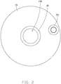
FIG. 2 is a top view of the battery ofFIG. 1 . -
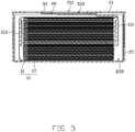
FIG. 3 is a cross-sectional view of the battery ofFIG. 1 . -
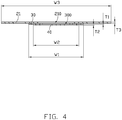
FIG. 4 is a cross-sectional view of a second casing, an insulating member, and a conductive member of the battery ofFIG. 3 . -
FIG. 5 is a cross-sectional view of the battery ofFIG. 1 in another embodiment. -
FIG. 6 is a cross-sectional view of a casing assembly of the battery ofFIG. 1 in another embodiment. -
FIG. 7 is a cross-sectional view of a casing assembly of the battery ofFIG. 1 in yet another embodiment. -
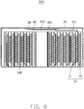
FIG. 8 is a cross-sectional view of the battery in yet another embodiment. -
FIG. 9 is a block diagram of an embodiment of a power consuming device according to the present disclosure. - Description of symbols for main elements: 1 represents a power consuming device, 10 represents a battery cell, 11 represents a first electrode plate, 12 represents a second electrode plate, 20 represents a casing assembly, 21 represents a second casing, 22 represents a first casing, 22a represents a bottom portion, 22b represents a sidewall, 30 represents an insulating member, 40 represents a conductive member, 100 and 200 represent a battery, 101 represents a first electrode tab, 102 represents a second electrode tab, 210 represents a first through hole, 211 represents a filling plug, 220 represents a receiving space, 300 represents a second through hole, Ti, T2, or T3 represents a thickness, and W1, W2, or W3 represents a width.
- Implementations of the disclosure will now be described, with reference to the drawings.
- Implementations of the disclosure will now be described, by way of embodiments only, with reference to the drawings. The disclosure is illustrative only, and changes may be made in the detail within the principles of the present disclosure. It will, therefore, be appreciated that the embodiments may be modified within the scope of the claims.
- Unless otherwise defined, all technical terms used herein have the same meaning as commonly understood by one of ordinary skill in the art. The technical terms used herein are not to be considered as limiting the scope of the embodiments.
- Implementations of the disclosure will now be described, by way of embodiments only, with reference to the drawings. It should be noted that non-conflicting details and features in the embodiments of the present disclosure may be combined with each other.
-
FIG. 1 to FIG. 4 illustrate an embodiment of abattery 100 including abattery cell 10 and acasing assembly 20 for receiving thebattery cell 10. Thebattery cell 10 includes afirst electrode tab 101. Thebattery 100 further includes an insulatingmember 30 and aconductive member 40. The insulatingmember 30 is connected between thecasing assembly 20 and theconductive member 40. Thecasing assembly 20 defines a first throughhole 210. The insulatingmember 30 defines a second throughhole 300 connected to the first throughhole 210. Thefirst electrode tab 101 is electrically connected to theconductive member 40. - Since the present disclosure electrically connects the
first electrode tab 101 to theconductive member 40, the polarity of thefirst electrode tab 101 may be guided out of thecasing assembly 20 when an external conductor is connected to theconductive member 40. Therefore, theconductive member 40 may be substituted for an existing terminal post. Compared to a conventional battery which adds four layers on its casing assembly when a terminal post is applied, the present disclosure only adds two layers, the insulatingmember 30 and theconductive member 40, on thecasing assembly 20. That is, a thickness of thecasing assembly 20 is reduced. While a total size of thebattery 100 remains unchanged, the energy density of thebattery 100 is increased. Furthermore, this arrangement avoids electrode plates of thebattery 100 being pierced by the terminal post during a crush test. Thus, a short circuit is avoided. - Referring to
FIGS. 1 to 4 , theconductive member 40 covers the second throughhole 300 and seals thebattery cell 10 in thecasing assembly 20. In other embodiments, the conductive member does not cover the second through hole. The battery is sealed by other components. - Referring to
FIG. 3 , in the embodiment, theconductive member 40 is adhered to thecasing assembly 20 through the insulatingmember 30. That is, the insulatingmember 30 not only electrically insulates theconductive member 40 from thecasing assembly 20, but also adhesively connects theconductive member 40 to thecasing assembly 20. Thus, theconductive member 40 seals the first throughhole 210 of thecasing assembly 20 to ensure the tightness of thecasing assembly 20. - Furthermore, the insulating
member 30 may be made of at least one of polyolefin, polyvinyl chloride, and fluoro-elastomer. For example, the insulatingmember 30 may be made of nonpolar polyolefin and insulating particles dispersed in the nonpolar polyolefin. The insulating particles ensure the insulating property of the insulatingmember 30. The nonpolar polyolefin may be selected from a group consisting of polyethylene (PE), polypropylene (PP), ethylene propylene diene monomer (EPDM), ethylene propylene rubber (EPR), ethylene-vinyl acetate copolymer (EVA), and any combination thereof. A size of the insulating particles may be in a range from 0.001 mm to 0.3 mm. - In another embodiment, the insulating
member 30 may also be connected to thecasing assembly 20 through thermal sealing, soldering, or injection molding. Theconductive member 40 may also be connected to the insulatingmember 30 through soldering. - Referring to
FIG. 3 , in the embodiment, the insulatingmember 30 and theconductive member 40 are disposed inside of thecasing assembly 20. Thus, a flat shape of thecase assembly 20 may be obtained, and the appearance of thebattery 100 is more regular. Furthermore, since there is a height difference between theconductive member 40 and a top surface of thecase assembly 20, an external short circuit is avoided. In this embodiment, the external conductor can pass through the first throughhole 210 and the second throughhole 300, and then connect to theconductive member 40. As such, the polarity of thefirst electrode tab 101 may be guided out of thecasing assembly 20. - Referring to
FIG. 5 , in another embodiment, the insulatingmember 30 and theconductive member 40 are disposed outside of thecasing assembly 20. Thebattery 100 may generate gas in thecasing assembly 20 during a normal operation, which results in an increase of internal pressure. When the internal pressure exceeds a predetermined value, theconductive member 40 is pushed away and separated from thecasing assembly 20 to achieve pressure relief. Thebattery 100 exploding is thus avoided to ensure the safety of thebattery 100. In this embodiment, thefirst electrode tab 101 can pass through the first throughhole 210 and the second throughhole 300, and then connect to theconductive member 40. When the external conductor is connected to theconductive member 40, the polarity of thefirst electrode tab 101 may be guided out of thecasing assembly 20. - Referring to
FIG. 4 , in the embodiment, a thickness T1 of the insulatingmember 30 is in a range from 0.01 mm to 0.3 mm. For example, the thickness T1 may be 0.15 mm. A thickness T2 of theconductive member 40 is in a range from 0.1 mm to 2 mm. For example, the thickness T2 may be 0.15 mm. Since the thicknesses of the insulatingmember 30 and theconductive member 40 are small, a total thickness of thebattery 100 is reduced. - Furthermore, a width W1 of the insulating
member 30 and a width W2 of theconductive member 40 are each not more than 1000 mm. The width W2 of theconductive member 40 may be less than the width W1 of the insulatingmember 30. The insulatingmember 30 and theconductive member 40 are substantially flat and extend along two planes parallel to each other. The width W1 is defined as being along any direction on the plane of the insulatingmember 30. The width W2 is defined as being along the same direction on the plane of theconductive member 40. - In the embodiment, the insulating
member 30 may be circular, square, oval, triangular, or polygonal. Theconductive member 40 may also be circular, square, oval, triangular, or polygonal. The shape of the insulatingmember 30 may be the same as that of theconductive member 40, or may also be different from that of theconductive member 40. - The
conductive member 40 may be made of a metal. For example, theconductive member 40 may be made of steel alloy, aluminum alloy, iron alloy, copper alloy, or nickel alloy. For example, theconductive member 40 may be made of iron-carbon alloy (i.e., stainless steel) or aluminum. - Referring to
FIG. 3 , in the embodiment, thecasing assembly 20 includes afirst casing 22 and asecond casing 21. Thefirst casing 22 defines a receivingspace 220 for receiving thebattery cell 10. Thesecond casing 21 is connected to thefirst casing 22 to close the receivingspace 220. The first throughhole 210 is defined on thesecond casing 21. In this embodiment, the insulatingmember 30 is connected between thesecond casing 21 and theconductive member 40. - Furthermore, the width W1 of the insulating
member 30 may be smaller than a width W3 of thesecond casing 21. Thesecond casing 21 is substantially flat and extends along a plane parallel to the insulatingmember 30. The width W1 is defined as being along any direction on the plane of the insulatingmember 30. The width W3 is defined as being along the same direction on the plane of thesecond casing 21. - Referring to
FIGS. 6 and7 , in another embodiment, the first throughhole 210 may also be disposed at any position of thefirst casing 22. In this embodiment, the insulatingmember 30 is connected between thefirst casing 22 and theconductive member 40. Thefirst casing 22 includes abottom portion 22a and asidewall 22b surrounding thebottom portion 22a. Thesecond casing 21 is opposite to thebottom portion 22a of thefirst casing 22. Referring toFIG. 6 , the first throughhole 210 may be disposed at thebottom portion 22a of thefirst casing 22. Referring toFIG. 7 , the first throughhole 210 may also be disposed at thesidewall 22b of thefirst casing 22. - The
first casing 22 may be made of a metal. For example, thefirst casing 22 may be made of steel alloy, aluminum alloy, iron alloy, copper alloy, or nickel alloy. For example, thefirst casing 22 is made of stainless steel. Thefirst casing 22 may also be made of a plastic which is resistant to electrolyte corrosion. For example, thefirst casing 22 may be made of polystyrene (PS), polypropylene (PP), polyethylene (PE), polyester (PET), polyvinyl chloride (PVC), polyimide (PI), acrylonitrile-butadiene-styrene plastic (ABS), polycarbonate (PC), or polyamide (PA). For example, thefirst casing 22 is made of polypropylene. Thefirst casing 22 may also be made of ceramic material. - The
second casing 21 may be made of a metal. For example, thesecond casing 21 may be made of steel alloy, aluminum alloy, iron alloy, copper alloy, or nickel alloy. For example, thesecond casing 21 is made of stainless steel. Thesecond casing 21 may also be made of a plastic which is resistant to electrolyte corrosion. For example, thesecond casing 21 may be made of polystyrene, polypropylene, polyethylene, polyester, polyvinyl chloride, polyimide, acrylonitrile-butadiene-styrene plastic, polycarbonate, or polyamide. For example, thesecond casing 21 is made of polypropylene. Thesecond casing 21 may also be made of ceramic material. - The cross-sections of the
first casing 22 and thesecond casing 21 may be circular, square, oval, triangular, or polygonal. - During manufacture, the
first casing 22 and thesecond casing 21 may be cut into a desired shape by laser cutting or machine tool processing. Thefirst casing 22 may also be formed by punching to form a recess (i.e., the receiving space). Thefirst casing 22 and thesecond casing 21 may be connected together by soldering or snap-fitted together. - In the embodiment, the
battery 100 may be a button battery. Thefirst casing 22 and thesecond casing 21 are made of stainless steel. Thefirst casing 22 and thesecond casing 21 are connected together by soldering. - Furthermore, a width of the
first casing 22 is not more than 1000 mm, and a height of thefirst casing 22 is not more than 1000 mm. Referring toFIG. 4 , the width W3 of thesecond casing 21 is not more than 1000 mm, and a thickness T3 of thesecond casing 21 is not more than 100 mm. - Referring to
FIG. 4 , in the embodiment, a central axis of the second throughhole 300 is aligned with a central axis of the first throughhole 210, and a projection of the second throughhole 300 on thesecond casing 21 is entirely disposed in the first throughhole 210. In another embodiment, the projection of the second throughhole 300 on thesecond casing 21 may also cover the first throughhole 210. - In another embodiment, the central axis of the second through
hole 300 is not aligned with the central axis of the first throughhole 210, and the projection of the second throughhole 300 on thesecond casing 21 is entirely disposed in the first throughhole 210 or covers the first throughhole 210. - Referring to
FIG. 1 andFIG. 2 , in the embodiment, the first throughhole 210 and the second throughhole 300 are circular, and a diameter of each of the first throughhole 210 and the second throughhole 300 is not more than 100 mm. For example, the diameter of each of the first throughhole 210 and the second throughhole 300 is nearly 12 mm. Furthermore, since theconductive member 40 covers the second throughhole 300, the width W2 of theconductive member 40 is greater than the diameter of the second throughhole 300. Moreover, the width W1 of the insulatingmember 30 is greater than the diameter of the first throughhole 210. In other embodiments, the first throughhole 210 and the second throughhole 300 are not limited to being circular, and may also be square, oval, triangular, or polygonal. - Referring to
FIG. 3 andFIG. 5 , in the embodiment, thebattery cell 10 further includes asecond electrode tab 102 having a polarity opposite that of thefirst electrode tab 101. Thesecond electrode tab 102 is electrically connected to thefirst casing 22. When thefirst casing 22 and thesecond casing 21 are connected together by soldering, theentire casing assembly 20 may have a polarity the same as that of thesecond electrode tab 102. Since thefirst electrode tab 101 is electrically connected to theconductive member 40, theconductive member 40 can have a polarity the same as that of thefirst electrode tab 101. Since theconductive member 40 and thesecond casing 21 are electrically insulated from each other by the insulatingmember 30, theconductive member 40 and thecasing assembly 20 may have opposite polarities. - In this embodiment, the
first electrode tab 101 is a positive electrode tab, and thesecond electrode tab 102 is a negative electrode tab. Thesecond electrode tab 102 may be electrically connected to thefirst casing 22 by soldering, and thefirst electrode tab 101 may be electrically connected to theconductive member 40 by soldering. - In another embodiment, the
second electrode tab 102 may also be electrically connected to thesecond casing 21, which also allows theconductive member 40 and thecasing assembly 20 to have opposite polarities. - Referring to
FIG. 3 andFIG. 5 , in the embodiment, thebattery cell 10 further includes afirst electrode plate 11 and asecond electrode plate 12. Thefirst electrode tab 101 and thesecond electrode tab 102 are electrically connected to thefirst electrode plate 11 and thesecond electrode plate 12, respectively. In detail, thefirst electrode plate 11 includes a first current collector and a first active material layer disposed on the first current collector. Thesecond electrode plate 12 includes a second current collector and a second active material layer disposed on the second current collector. Thefirst electrode tab 101 and thesecond electrode tab 102 are respectively electrically connected to the first current collector and the second current collector through soldering. Thefirst electrode plate 11 and thesecond electrode plate 12 are stacked together to form thebattery cell 10. An isolation film (not shown) may be further disposed between thefirst electrode plate 11 and thesecond electrode plate 12. - Referring to
FIG. 1 andFIG. 2 , in at least one embodiment, thesecond casing 21 includes a liquid injection hole (not shown). A liquid electrolyte may be injected into the battery through the liquid injection hole. A fillingplug 211 is disposed in the liquid injection hole. The fillingplug 211 seals the liquid injection hole, avoids leakage of the electrolyte, and prevents external impurities from entering thebattery 100. The liquid injection hole can also be defined on thefirst casing 22. - Referring to
FIG. 8 , the present disclosure further provides another embodiment of abattery 200. Different from thebattery 100, thebattery 200 is of the wound type. That is, thefirst electrode plate 11 and thesecond electrode plate 12 are wound to form thebattery cell 10. - Referring to
FIG. 9 , the present disclosure further provides apower consuming device 1, which includes thebattery 100 or thebattery 200. Thepower consuming device 1 may be a consumer electronic product, such as a smart phone. In other embodiments, thepower consuming device 1 may also be an electric tool, an energy storage device, or a power device. For example, thepower consuming device 1 may be an electric vehicle. - The embodiments shown and described above are only examples. Therefore, many commonly-known features and details are neither shown nor described. Even though numerous characteristics and advantages of the present technology have been set forth in the foregoing description, together with details of the structure and function of the present disclosure, the disclosure is illustrative only, and changes may be made in the detail, including in matters of shape, size, and arrangement of the parts within the principles of the present disclosure, up to and including the full extent established by the broad general meaning of the terms used in the claims. It will, therefore, be appreciated that the embodiments described above may be modified within the scope of the claims.
Claims (16)
- A battery comprising:a battery cell comprising a first electrode tab;a casing assembly receiving the battery cell;characterized in that, the battery further comprises an insulating member and a conductive member, the insulating member being connected between the casing assembly and the conductive member;the casing assembly defines a first through hole, the insulating member defines a second through hole connected to the first through hole, and the first electrode tab is electrically connected to the conductive member.
- The battery of claim 1, characterized in that the conductive member covers the second through hole and seals the battery cell received in the casing assembly.
- The battery of claim 1, characterized in that the conductive member is adhered to the casing assembly through the insulating member.
- The battery of claim 1, characterized in that the insulating member is made of at least one of polyolefin, polyvinyl chloride, and fluoro-elastomer.
- The battery of claim 4, characterized in that the insulating member is made of nonpolar polyolefin and insulating particles dispersed in the nonpolar polyolefin.
- The battery of claim 1, characterized in that the insulating member and the conductive member are disposed inside of the casing assembly.
- The battery of claim 1, characterized in that the insulating member and the conductive member are disposed outside of the casing assembly.
- The battery of claim 1, characterized in that a thickness of the insulating member is in a range from 0.01 mm to 0.3 mm, and a thickness of the conductive member is in a range from 0.1 mm to 2 mm.
- The battery of claim 1, characterized in that the casing assembly comprises a first casing and a second casing, the first casing defines a receiving space configured for receiving the battery cell, the second casing is connected to the first casing and closes the receiving space, and the first through hole is defined on the second casing.
- The battery of claim 9, characterized in that a central axis of the second through hole is aligned with a central axis of the first through hole, and a projection of the second through hole on the second casing is entirely disposed in the first through hole or covers the first through hole.
- The battery of claim 9, characterized in that a central axis of the second through hole is not aligned with a central axis of the first through hole, and a projection of the second through hole on the second casing is entirely disposed in the first through hole or covers the first through hole.
- The battery of claim 9, characterized in that a width of the insulating member is smaller than a width of the second casing, and a width of the conductive member is less than the width of the insulating member.
- The battery of claim 9, characterized in that the battery cell further comprises a second electrode tab having a polarity different from a polarity of the first electrode tab, and the second electrode tab is electrically connected to the first casing.
- The battery of claim 13, wherein the battery cell further comprises a first electrode plate and a second electrode plate, the first electrode tab and the second electrode tab are electrically connected to the first electrode plate and the second electrode plate, respectively, the first electrode plate and the second electrode plate are stacked or wound to form the battery cell.
- The battery of claim 1, characterized in that the first through hole and the second through hole are circular, and a diameter of each of the first through hole and the second through hole is not more than 100 mm.
- A power consuming device comprising:
a battery of any one of claims 1-15.
Applications Claiming Priority (1)
| Application Number | Priority Date | Filing Date | Title |
|---|---|---|---|
| PCT/CN2020/074482 WO2021155560A1 (en) | 2020-02-07 | 2020-02-07 | Battery and powered apparatus provided with battery |
Publications (2)
| Publication Number | Publication Date |
|---|---|
| EP3886239A1 true EP3886239A1 (en) | 2021-09-29 |
| EP3886239A4 EP3886239A4 (en) | 2021-09-29 |
Family
ID=77199706
Family Applications (1)
| Application Number | Title | Priority Date | Filing Date |
|---|---|---|---|
| EP20712824.0A Pending EP3886239A4 (en) | 2020-02-07 | 2020-02-07 | BATTERY AND POWER CONSUMPTION DEVICE WITH IT |
Country Status (6)
| Country | Link |
|---|---|
| US (2) | US11901590B2 (en) |
| EP (1) | EP3886239A4 (en) |
| JP (1) | JP7330955B2 (en) |
| KR (3) | KR102490178B1 (en) |
| CN (1) | CN113557630A (en) |
| WO (1) | WO2021155560A1 (en) |
Cited By (3)
| Publication number | Priority date | Publication date | Assignee | Title |
|---|---|---|---|---|
| EP3968443A4 (en) * | 2020-07-14 | 2022-03-16 | Ningde Amperex Technology Ltd. | BATTERY AND ELECTRICAL DEVICE EQUIPPED WITH SAID BATTERY |
| EP4156386A4 (en) * | 2020-12-04 | 2024-01-24 | Zhuhai CosMX Battery Co., Ltd. | BUTTON CELL AND ELECTRONIC DEVICE |
| US12021270B2 (en) | 2020-07-17 | 2024-06-25 | Dongguan Poweramp Technology Limited | Battery cell module and battery pack |
Families Citing this family (7)
| Publication number | Priority date | Publication date | Assignee | Title |
|---|---|---|---|---|
| EP4142039A4 (en) * | 2020-04-21 | 2025-01-22 | Samsung SDI Co., Ltd. | Secondary battery |
| KR102907169B1 (en) * | 2020-04-29 | 2025-12-31 | 삼성에스디아이 주식회사 | Rechargeable battery |
| KR20210158162A (en) * | 2020-06-23 | 2021-12-30 | 삼성에스디아이 주식회사 | Secondary battery |
| KR20220003395A (en) * | 2020-07-01 | 2022-01-10 | 삼성에스디아이 주식회사 | Rechargeable battery |
| CN114938691B (en) * | 2021-10-29 | 2024-07-02 | 宁德新能源科技有限公司 | Electrochemical device and electric equipment |
| CN114284570B (en) * | 2021-12-28 | 2024-06-21 | 宁德新能源科技有限公司 | Cells, batteries and electrical equipment |
| CN114552080A (en) * | 2022-02-21 | 2022-05-27 | 东莞市电的电子有限公司 | Button battery and surface treatment process of cover cap thereof |
Family Cites Families (29)
| Publication number | Priority date | Publication date | Assignee | Title |
|---|---|---|---|---|
| JPS56156666A (en) | 1980-05-07 | 1981-12-03 | Yuasa Battery Co Ltd | Lithium-iodine battery |
| JPH06248102A (en) * | 1992-12-28 | 1994-09-06 | Nippon Petrochem Co Ltd | Insulating material |
| US6083639A (en) * | 1997-08-22 | 2000-07-04 | Duracell Inc. | Current interrupter for electrochemical cells |
| KR101233573B1 (en) | 2011-01-27 | 2013-02-14 | 로베르트 보쉬 게엠베하 | Secondary battery |
| KR101577330B1 (en) * | 2011-11-01 | 2015-12-15 | 히다치 막셀 가부시키가이샤 | Sealed cell |
| JP6017873B2 (en) * | 2012-07-27 | 2016-11-02 | トヨタ自動車株式会社 | Sealed battery |
| US20150007943A1 (en) | 2013-07-08 | 2015-01-08 | Upm Raflatac Oy | Label, and an apparatus and a method for providing a label |
| KR20150032086A (en) * | 2013-09-17 | 2015-03-25 | 삼성에스디아이 주식회사 | Rechargeable battery having safty member |
| CN204289638U (en) | 2014-11-25 | 2015-04-22 | 江苏威盛电源有限公司 | Storage battery |
| KR101798926B1 (en) * | 2015-01-26 | 2017-11-17 | 주식회사 엘지화학 | Secondary Battery Having Insulative Member with Improved Structural Stability against External Force |
| CN204596909U (en) | 2015-03-25 | 2015-08-26 | 深圳金山电池有限公司 | A kind of Novel button lithium ion battery |
| KR102517901B1 (en) | 2015-10-02 | 2023-04-03 | 삼성에스디아이 주식회사 | Rechargeable battery |
| US11069916B2 (en) * | 2016-03-25 | 2021-07-20 | Sanyo Electric Co., Ltd. | Cylindrical battery |
| WO2018139453A1 (en) * | 2017-01-25 | 2018-08-02 | 三洋電機株式会社 | Secondary cell |
| KR102285642B1 (en) * | 2017-04-28 | 2021-08-04 | 주식회사 엘지에너지솔루션 | Battery Cell Comprising Electrode Lead Facing Outer Surface of Electrode Assembly |
| JP2019029225A (en) * | 2017-07-31 | 2019-02-21 | リチウム エナジー アンド パワー ゲゼルシャフト ミット ベシュレンクテル ハフッング ウント コンパニー コマンディトゲゼルシャフトLithium Energy and Power GmbH & Co. KG | Electricity storage element |
| JP7205050B2 (en) | 2017-09-01 | 2023-01-17 | 株式会社村田製作所 | Sealed power storage device |
| CN109659483B (en) | 2017-10-11 | 2021-08-03 | 宁德时代新能源科技股份有限公司 | Secondary battery top cover assembly and secondary battery |
| CN207381439U (en) | 2017-10-20 | 2018-05-18 | 宁德时代新能源科技股份有限公司 | Secondary battery top cover assembly and secondary battery |
| JP2019087341A (en) | 2017-11-02 | 2019-06-06 | 株式会社Gsユアサ | Power storage element |
| DE102018200159A1 (en) * | 2018-01-08 | 2019-07-11 | Robert Bosch Gmbh | Lid assembly for a battery cell and method of making the same |
| JP7453740B2 (en) * | 2018-03-29 | 2024-03-21 | 三洋電機株式会社 | Power storage device |
| CN208433426U (en) | 2018-04-27 | 2019-01-25 | 广东微电新能源有限公司 | Caps for batteries and batteries |
| CN208336402U (en) | 2018-07-04 | 2019-01-04 | 惠州市智键科技有限公司 | A kind of filled type button lithium ion battery |
| CN109192889B (en) * | 2018-08-22 | 2024-01-26 | 珠海微矩实业有限公司 | Micro battery |
| KR102711972B1 (en) * | 2018-10-08 | 2024-10-02 | 삼성에스디아이 주식회사 | Battery pack |
| CN109546018B (en) * | 2018-11-27 | 2021-09-17 | 欣旺达电子股份有限公司 | Battery top cover and power battery using same |
| CN209199997U (en) | 2019-01-22 | 2019-08-02 | 深圳市小机灵精密机械有限公司 | A kind of no pole ternary lithium battery cover plate |
| CN110048037A (en) | 2019-04-15 | 2019-07-23 | 欣旺达电子股份有限公司 | A kind of no pole power battery top cover and power battery |
-
2020
- 2020-02-07 JP JP2020518626A patent/JP7330955B2/en active Active
- 2020-02-07 CN CN202080000174.1A patent/CN113557630A/en active Pending
- 2020-02-07 KR KR1020207009402A patent/KR102490178B1/en active Active
- 2020-02-07 US US16/650,488 patent/US11901590B2/en active Active
- 2020-02-07 KR KR1020237001490A patent/KR102537762B1/en active Active
- 2020-02-07 WO PCT/CN2020/074482 patent/WO2021155560A1/en not_active Ceased
- 2020-02-07 EP EP20712824.0A patent/EP3886239A4/en active Pending
- 2020-02-07 KR KR1020237017381A patent/KR102561627B1/en active Active
-
2023
- 2023-12-29 US US18/400,838 patent/US12294119B2/en active Active
Cited By (4)
| Publication number | Priority date | Publication date | Assignee | Title |
|---|---|---|---|---|
| EP3968443A4 (en) * | 2020-07-14 | 2022-03-16 | Ningde Amperex Technology Ltd. | BATTERY AND ELECTRICAL DEVICE EQUIPPED WITH SAID BATTERY |
| US12183954B2 (en) | 2020-07-14 | 2024-12-31 | Ningde Amperex Technology Limited | Battery and electric device containing same |
| US12021270B2 (en) | 2020-07-17 | 2024-06-25 | Dongguan Poweramp Technology Limited | Battery cell module and battery pack |
| EP4156386A4 (en) * | 2020-12-04 | 2024-01-24 | Zhuhai CosMX Battery Co., Ltd. | BUTTON CELL AND ELECTRONIC DEVICE |
Also Published As
| Publication number | Publication date |
|---|---|
| US20240136679A1 (en) | 2024-04-25 |
| KR20210102835A (en) | 2021-08-20 |
| US12294119B2 (en) | 2025-05-06 |
| WO2021155560A1 (en) | 2021-08-12 |
| CN113557630A (en) | 2021-10-26 |
| KR20230016028A (en) | 2023-01-31 |
| KR102537762B1 (en) | 2023-05-26 |
| KR102561627B1 (en) | 2023-07-31 |
| JP2022522546A (en) | 2022-04-20 |
| KR102490178B1 (en) | 2023-01-18 |
| EP3886239A4 (en) | 2021-09-29 |
| JP7330955B2 (en) | 2023-08-22 |
| US11901590B2 (en) | 2024-02-13 |
| KR20230084310A (en) | 2023-06-12 |
| US20210408650A1 (en) | 2021-12-30 |
Similar Documents
| Publication | Publication Date | Title |
|---|---|---|
| US12294119B2 (en) | Battery and power consuming device having the same | |
| US11996570B2 (en) | Battery casing assembly and battery having the same | |
| JP4235538B2 (en) | Secondary battery unit | |
| JP4963609B2 (en) | Secondary battery | |
| US9564626B2 (en) | Rechargeable battery | |
| JP2007035638A (en) | Secondary battery | |
| US11108095B2 (en) | Secondary battery | |
| CN100438189C (en) | secondary battery | |
| EP2899779B1 (en) | Secondary battery | |
| US11522256B2 (en) | Secondary battery | |
| US12183954B2 (en) | Battery and electric device containing same | |
| EP2477257A1 (en) | Secondary battery | |
| KR20060112743A (en) | Cap assembly and a lithium ion secondary battery having the same | |
| WO2021237711A1 (en) | Battery and electrical device having same | |
| KR102043458B1 (en) | Secondary Battery | |
| CN117044014A (en) | End cap assemblies, battery cells, batteries and devices using batteries | |
| US20250105407A1 (en) | Secondary battery | |
| KR20200106694A (en) | Secondary battery | |
| KR100686837B1 (en) | Secondary battery | |
| KR20260054750A (en) | Battery module and electronic device using the same | |
| KR20250173898A (en) | Secondary battery |
Legal Events
| Date | Code | Title | Description |
|---|---|---|---|
| STAA | Information on the status of an ep patent application or granted ep patent |
Free format text: STATUS: UNKNOWN |
|
| STAA | Information on the status of an ep patent application or granted ep patent |
Free format text: STATUS: THE INTERNATIONAL PUBLICATION HAS BEEN MADE |
|
| PUAI | Public reference made under article 153(3) epc to a published international application that has entered the european phase |
Free format text: ORIGINAL CODE: 0009012 |
|
| STAA | Information on the status of an ep patent application or granted ep patent |
Free format text: STATUS: REQUEST FOR EXAMINATION WAS MADE |
|
| 17P | Request for examination filed |
Effective date: 20200331 |
|
| A4 | Supplementary search report drawn up and despatched |
Effective date: 20210628 |
|
| AK | Designated contracting states |
Kind code of ref document: A1 Designated state(s): AL AT BE BG CH CY CZ DE DK EE ES FI FR GB GR HR HU IE IS IT LI LT LU LV MC MK MT NL NO PL PT RO RS SE SI SK SM TR |
|
| DAV | Request for validation of the european patent (deleted) | ||
| DAX | Request for extension of the european patent (deleted) | ||
| STAA | Information on the status of an ep patent application or granted ep patent |
Free format text: STATUS: EXAMINATION IS IN PROGRESS |
|
| 17Q | First examination report despatched |
Effective date: 20241220 |