EP3886064A1 - Sales data processing device and method - Google Patents
Sales data processing device and method Download PDFInfo
- Publication number
- EP3886064A1 EP3886064A1 EP21162373.1A EP21162373A EP3886064A1 EP 3886064 A1 EP3886064 A1 EP 3886064A1 EP 21162373 A EP21162373 A EP 21162373A EP 3886064 A1 EP3886064 A1 EP 3886064A1
- Authority
- EP
- European Patent Office
- Prior art keywords
- data processing
- mode
- scanner
- sales data
- processing device
- Prior art date
- Legal status (The legal status is an assumption and is not a legal conclusion. Google has not performed a legal analysis and makes no representation as to the accuracy of the status listed.)
- Withdrawn
Links
Images


Classifications
-
- G—PHYSICS
- G06—COMPUTING OR CALCULATING; COUNTING
- G06Q—INFORMATION AND COMMUNICATION TECHNOLOGY [ICT] SPECIALLY ADAPTED FOR ADMINISTRATIVE, COMMERCIAL, FINANCIAL, MANAGERIAL OR SUPERVISORY PURPOSES; SYSTEMS OR METHODS SPECIALLY ADAPTED FOR ADMINISTRATIVE, COMMERCIAL, FINANCIAL, MANAGERIAL OR SUPERVISORY PURPOSES, NOT OTHERWISE PROVIDED FOR
- G06Q20/00—Payment architectures, schemes or protocols
- G06Q20/08—Payment architectures
- G06Q20/20—Point-of-sale [POS] network systems
- G06Q20/208—Input by product or record sensing, e.g. weighing or scanner processing
-
- G—PHYSICS
- G07—CHECKING-DEVICES
- G07G—REGISTERING THE RECEIPT OF CASH, VALUABLES, OR TOKENS
- G07G1/00—Cash registers
- G07G1/0018—Constructional details, e.g. of drawer, printing means, input means
-
- G—PHYSICS
- G07—CHECKING-DEVICES
- G07G—REGISTERING THE RECEIPT OF CASH, VALUABLES, OR TOKENS
- G07G1/00—Cash registers
- G07G1/0009—Details of the software in the checkout register, electronic cash register [ECR] or point of sale terminal [POS]
-
- G—PHYSICS
- G06—COMPUTING OR CALCULATING; COUNTING
- G06Q—INFORMATION AND COMMUNICATION TECHNOLOGY [ICT] SPECIALLY ADAPTED FOR ADMINISTRATIVE, COMMERCIAL, FINANCIAL, MANAGERIAL OR SUPERVISORY PURPOSES; SYSTEMS OR METHODS SPECIALLY ADAPTED FOR ADMINISTRATIVE, COMMERCIAL, FINANCIAL, MANAGERIAL OR SUPERVISORY PURPOSES, NOT OTHERWISE PROVIDED FOR
- G06Q20/00—Payment architectures, schemes or protocols
- G06Q20/08—Payment architectures
- G06Q20/20—Point-of-sale [POS] network systems
- G06Q20/209—Specified transaction journal output feature, e.g. printed receipt or voice output
-
- G—PHYSICS
- G07—CHECKING-DEVICES
- G07D—HANDLING OF COINS OR VALUABLE PAPERS, e.g. TESTING, SORTING BY DENOMINATIONS, COUNTING, DISPENSING, CHANGING OR DEPOSITING
- G07D1/00—Coin dispensers
- G07D1/02—Coin dispensers giving change
- G07D1/06—Coin dispensers giving change dispensing the difference between a sum paid and a sum charged
-
- G—PHYSICS
- G07—CHECKING-DEVICES
- G07D—HANDLING OF COINS OR VALUABLE PAPERS, e.g. TESTING, SORTING BY DENOMINATIONS, COUNTING, DISPENSING, CHANGING OR DEPOSITING
- G07D11/00—Devices accepting coins; Devices accepting, dispensing, sorting or counting valuable papers
- G07D11/60—User-interface arrangements
-
- G—PHYSICS
- G07—CHECKING-DEVICES
- G07G—REGISTERING THE RECEIPT OF CASH, VALUABLES, OR TOKENS
- G07G1/00—Cash registers
- G07G1/0036—Checkout procedures
- G07G1/0045—Checkout procedures with a code reader for reading of an identifying code of the article to be registered, e.g. barcode reader or radio-frequency identity [RFID] reader
-
- G—PHYSICS
- G07—CHECKING-DEVICES
- G07G—REGISTERING THE RECEIPT OF CASH, VALUABLES, OR TOKENS
- G07G1/00—Cash registers
- G07G1/0036—Checkout procedures
- G07G1/0045—Checkout procedures with a code reader for reading of an identifying code of the article to be registered, e.g. barcode reader or radio-frequency identity [RFID] reader
- G07G1/0054—Checkout procedures with a code reader for reading of an identifying code of the article to be registered, e.g. barcode reader or radio-frequency identity [RFID] reader with control of supplementary check-parameters, e.g. weight or number of articles
-
- G—PHYSICS
- G07—CHECKING-DEVICES
- G07G—REGISTERING THE RECEIPT OF CASH, VALUABLES, OR TOKENS
- G07G1/00—Cash registers
- G07G1/01—Details for indicating
-
- H—ELECTRICITY
- H04—ELECTRIC COMMUNICATION TECHNIQUE
- H04N—PICTORIAL COMMUNICATION, e.g. TELEVISION
- H04N1/00—Scanning, transmission or reproduction of documents or the like, e.g. facsimile transmission; Details thereof
- H04N1/0035—User-machine interface; Control console
- H04N1/00352—Input means
- H04N1/00384—Key input means, e.g. buttons or keypads
-
- H—ELECTRICITY
- H04—ELECTRIC COMMUNICATION TECHNIQUE
- H04N—PICTORIAL COMMUNICATION, e.g. TELEVISION
- H04N1/00—Scanning, transmission or reproduction of documents or the like, e.g. facsimile transmission; Details thereof
- H04N1/0035—User-machine interface; Control console
- H04N1/00405—Output means
- H04N1/00408—Display of information to the user, e.g. menus
- H04N1/00411—Display of information to the user, e.g. menus the display also being used for user input, e.g. touch screen
-
- G—PHYSICS
- G06—COMPUTING OR CALCULATING; COUNTING
- G06K—GRAPHICAL DATA READING; PRESENTATION OF DATA; RECORD CARRIERS; HANDLING RECORD CARRIERS
- G06K7/00—Methods or arrangements for sensing record carriers, e.g. for reading patterns
- G06K7/10—Methods or arrangements for sensing record carriers, e.g. for reading patterns by electromagnetic radiation, e.g. optical sensing; by corpuscular radiation
- G06K2007/10524—Hand-held scanners
-
- G—PHYSICS
- G06—COMPUTING OR CALCULATING; COUNTING
- G06K—GRAPHICAL DATA READING; PRESENTATION OF DATA; RECORD CARRIERS; HANDLING RECORD CARRIERS
- G06K7/00—Methods or arrangements for sensing record carriers, e.g. for reading patterns
- G06K7/10—Methods or arrangements for sensing record carriers, e.g. for reading patterns by electromagnetic radiation, e.g. optical sensing; by corpuscular radiation
- G06K7/14—Methods or arrangements for sensing record carriers, e.g. for reading patterns by electromagnetic radiation, e.g. optical sensing; by corpuscular radiation using light without selection of wavelength, e.g. sensing reflected white light
- G06K7/1404—Methods for optical code recognition
- G06K7/1408—Methods for optical code recognition the method being specifically adapted for the type of code
- G06K7/1413—1D bar codes
-
- G—PHYSICS
- G07—CHECKING-DEVICES
- G07D—HANDLING OF COINS OR VALUABLE PAPERS, e.g. TESTING, SORTING BY DENOMINATIONS, COUNTING, DISPENSING, CHANGING OR DEPOSITING
- G07D11/00—Devices accepting coins; Devices accepting, dispensing, sorting or counting valuable papers
- G07D11/10—Mechanical details
- G07D11/14—Inlet or outlet ports
-
- G—PHYSICS
- G07—CHECKING-DEVICES
- G07D—HANDLING OF COINS OR VALUABLE PAPERS, e.g. TESTING, SORTING BY DENOMINATIONS, COUNTING, DISPENSING, CHANGING OR DEPOSITING
- G07D2201/00—Coin dispensers
-
- G—PHYSICS
- G07—CHECKING-DEVICES
- G07D—HANDLING OF COINS OR VALUABLE PAPERS, e.g. TESTING, SORTING BY DENOMINATIONS, COUNTING, DISPENSING, CHANGING OR DEPOSITING
- G07D2211/00—Paper-money handling devices
Definitions
- the touch panel is integrated with the display.
- the settlement processing is a process of displaying the total amount of money due in the transaction (based on the commodity information stored in the RAM or the like in the registration processing), a process of calculating and displaying change due amount based on the deposit received from the customer, and a process of instructing the change dispenser to dispense the change due.
- the settlement processing also can also include a process of dispensing a receipt on which registered commodity information and settlement information (total amount, deposit amount, change amount, and the like) are printed.
Landscapes
- General Physics & Mathematics (AREA)
- Physics & Mathematics (AREA)
- Business, Economics & Management (AREA)
- Engineering & Computer Science (AREA)
- Accounting & Taxation (AREA)
- Multimedia (AREA)
- Signal Processing (AREA)
- Finance (AREA)
- Strategic Management (AREA)
- General Business, Economics & Management (AREA)
- Theoretical Computer Science (AREA)
- Human Computer Interaction (AREA)
- Cash Registers Or Receiving Machines (AREA)
Abstract
Description
- Embodiments described herein relate generally to a sales data processing device, such as a point-of-sales terminal, and a method of operating such a sales data processing apparatus.
- In recent years, in stores such as supermarkets, convenience stores, and mass merchandisers, there is a case in which the commodity data processing and settlement processing (collectively referred to as "transaction processing" or "checkout processing") at the sales data processing devices at the store can be switched between a clerk mode and a self-service mode. In the clerk mode, transaction processing at a sales data processing device, such as point-of-sales (POS) terminal, is performed by a store clerk. In a self-service mode, transaction processing (or at least some aspects thereof) is performed at a sales data processing device by the customer alone. At a busy time of the store, a clerk may switch a POS terminal to the clerk mode and performs the transaction processing. However, in a quiet time, all or some of the POS terminals at the store may be switched to the self-service mode so the customer can perform the transaction processing operations.
- However, in order to switch a POS terminal from the clerk mode to the self-service mode, or to switch a POS terminal from the self-service mode to the clerk mode, typically, the POS terminal, as a whole, must be rotated by about 180° to switch between facing the clerk position or the customer position, as shown in the related art (see, for example,
JP-A-2010-20370 -
-
FIG. 1 is a perspective view showing a POS terminal and peripheral devices. -
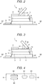
FIG. 2 is an explanatory diagram showing a POS terminal operating in a clerk mode. -
FIG. 3 is an explanatory diagram showing a POS terminal operating in a self-service mode. -
FIG. 4 is an explanatory diagram schematically showing a front surface (operation surface) of an automatic change dispenser. -
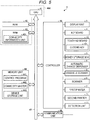
FIG. 5 is a block diagram of a POS terminal. -
FIG. 6 is a schematic memory map or data structure of a device storage unit. -
FIG. 7 is a block diagram showing schematic functional aspects of a POS terminal. -
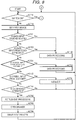
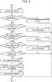
FIG. 8 is a flowchart of aspects of control processing of a POS terminal. -
FIG. 9 is a flowchart of aspects of control processing of a POS terminal. - At least one embodiment of the present disclosure provides a sales data processing device and a method of operating a sales data processing device that permits the sales data processing device to be easily switched back and forth between a clerk mode and a self-service mode.
- In general, according to one embodiment, a sales data processing device includes a display configured to rotate to face a first direction, from which a clerk operates the sale data processing device in a first mode, and a second direction different from the first direction, from which a customer operates the sales data processing device in a second mode. A detection unit is configured to detect whether the display faces the first direction or the second direction and indicate the first or second mode according to the detected first or second direction. A processor is configured to enable a first group of components to be operated in the first mode and to enable a second group of components to be operated in the second mode according to the indicated first or second mode of the detection unit.
- Preferably, the first group includes a first keyboard to be operated by a clerk, and the second group includes a touch panel integrated with the display.
- Preferably, the first group includes a first scanner that allows the clerk to read commodity information, the second group includes a second scanner that allows the customer to read commodity information.
- Preferably, the first scanner is a hand-held scanner.
- Preferably, the second scanner is a fixed scanner.
- Preferably, the detection unit comprises a mechanical switch configured to be activated by movement of the display to face the second direction.
- Preferably, the first group includes a cash drawer, and the second group includes an automatic change dispenser.
- Preferably, the first group includes a first printer, and the second group includes a second printer used when the customer operates the sales data processing device.
- The sales data processing apparatus may be configured as a point-of-sales terminal.
- There is also provided a non-transitory computer readable storage medium storing program instructions which, when executed by a processor of a sales data processing device having a display configured to rotate to face a first direction, from which a clerk operates the sale data processing device in a first mode, and a second direction different from the first direction, from which a customer operates the sales data processing device in a second mode, and a detection unit configured to detect whether the display faces the first direction or the second direction and indicate the first or second mode according to the detected first or second direction, cause the processor to perform a method comprising: enabling a first group of components to be operated for sales data processing when the first mode is indicated by the detection unit; and enabling a second group of components to be operated in for sales data processing when the second mode is indicated by the detection unit, wherein the first group and the second group are different from each other.
- Preferably, the first group includes a first keyboard, a first scanner, a cash drawer, and a first printer, and the second group includes a touch panel, a second scanner, a change dispenser, and a second printer.
- Preferably, the touch panel is integrated with the display.
- Preferably, the first scanner is a hand-held scanner.
- Preferably, the second scanner is a fixed scanner.
- Hereinafter, certain example embodiments will be described with reference to the drawings. In the example embodiments, a point of sales (POS) terminal will be described as one example of a sales data processing device, but the present disclosure is not limited to these example embodiments.
-
FIG. 1 is a perspective view showing an external appearance of aPOS terminal 1 of an embodiment and some peripheral devices connected to thePOS terminal 1. - Placement tables S can be arranged side by side in a store checkout region of the store. In some examples, only a single placement table S may be provided. The placement table S has a substantially rectangular surface and is a table on which the
POS terminal 1, amoney storage box 3, and anautomatic change dispenser 6 are placed. One side of the placement table S (facing side inFIG. 1 ) is a clerk side ST where a clerk is to be located, and the other side (far side inFIG. 1 ) of the placement table S is a customer side SK where a customer is to be located. - In a transaction with a customer, the
POS terminal 1 executes registration processing (processing related to obtaining commodity data for items being purchased in the transaction) and settlement processing for commodities being purchased by the customer. ThePOS terminal 1 reads code symbol, such as a barcode, attached to a commodity being purchased in the transaction and acquires a commodity code for specifying the corresponding commodity. The data processing executed based on the reading of the code symbol is a process by which thePOS terminal 1 displays the commodity name and price of the corresponding commodity and also stores the commodity information in a commodity information unit (a registered item list) or the like, based on commodity information (commodity name, price, and the like) of the registered commodity obtained based on the acquired commodity code. In some examples,POS terminal 1 may capture an image of the commodity being registered and acquire the corresponding commodity code for the commodity based on the captured image. - The settlement processing is a process of displaying the total amount of money due in the transaction (based on the commodity information stored in the RAM or the like in the registration processing), a process of calculating and displaying change due amount based on the deposit received from the customer, and a process of instructing the change dispenser to dispense the change due. The settlement processing also can also include a process of dispensing a receipt on which registered commodity information and settlement information (total amount, deposit amount, change amount, and the like) are printed.
- The
POS terminal 1 includes amain body 2 andmoney storage box 3. Themain body 2 has a power supply unit and a control circuit board built therein. In this example,main body 2 includes akeyboard 4, adisplay unit 5, afirst printer 7, and a touch screen 10 (integrated with display unit 5). Further, themain body 2 is connected to a hand-heldscanner 9 that can read a barcode attached to a commodity. Themoney storage box 3 includes adrawer 31 that can be opened toward the clerk side ST and thedrawer 31 stores money received from the customer or reserve money to be handed to the customer as change. - The keyboard 4 (first device, first keyboard) is a keyboard operated by a clerk. The
keyboard 4 is a keyboard provided in thePOS terminal 1 and includes numeric keys for entering numbers and various function keys. - The
display unit 5 is composed of, for example, a liquid crystal display. Thedisplay unit 5 displays characters and images on adisplay surface 52. Thedisplay unit 5 is configured to be horizontally rotatable about a support shaft 51 (seeFIGS. 2 and 3 ). Thedisplay unit 5 turns thedisplay surface 52 around thesupport shaft 51 toward the clerk side ST (first direction). When operating thePOS terminal 1, the clerk turns thedisplay unit 5 toward the clerk side ST. Further, thedisplay unit 5 turns thedisplay surface 52 around thesupport shaft 51 toward the customer side SK (second direction). When operating thePOS terminal 1, the customer turns thedisplay unit 5 toward the customer side SK. - The
touch screen 10 configured of a transparent touch panel is provided on the surface of thedisplay unit 5. A clerk or a customer operates thetouch screen 10 by pressing a position corresponding to a key displayed on thedisplay unit 5. By doing so, thetouch screen 10 permits selection of the keys, icons, and/or buttons displayed on thedisplay unit 5. Thetouch screen 10 provides, for example, a commodity key for selecting a commodity, a closingkey 101 that is to be operated for ending the commodity registration processing and moving to a closing (settlement) operation, or the like. - The first printer 7 (includes a thermal head, a storage unit for storing roll-shaped receipt paper, a conveyance unit (none of which is shown), and the like. The conveyance unit pulls out one end of the receipt paper from the storage unit and conveys the receipt paper, and the thermal head prints commodity information, settlement information, and the like regarding the commodity on the conveyed receipt paper. The
first printer 7 dispenses the printed receipt toward the clerk side ST. The clerk receives the receipt dispensed by thefirst printer 7. - Further, the
POS terminal 1 is connected to the money storage box 3 (first device). Themoney storage box 3 is installed under thePOS terminal 1. Themoney storage box 3 may be referred to as acash drawer 3 in some instances. Themoney storage box 3 stores thedrawer 31 inside. Themoney storage box 3 opens thedrawer 31 to the clerk side ST in response to an opening signal from thePOS terminal 1. Further, the openeddrawer 31 is closed in themoney storage box 3 by the clerk. Thedrawer 31 stores marketable securities including money such as coins and bills. The clerk deposits the purchase price of the commodity from the customer and stores the money in thedrawer 31. Further, the clerk takes out the change to be handed to the customer from thedrawer 31. - Further, the
POS terminal 1 is connected to the automatic change dispenser 6 (second device). Theautomatic change dispenser 6 is concerned with the price of commodity, stores the money input by the customer themselves, and pays out the change amount to the customer. Theautomatic change dispenser 6 will be described later with reference toFIG. 4 . - Further, the
POS terminal 1 connects to the handheld scanner 9 (also referred to as a "touch scanner"). Thehandheld scanner 9 reads a symbol attached to a commodity by a clerk holding in hand. ThePOS terminal 1 acquires a commodity code that specifies the commodity based on the read symbol. - Further, as will be described in detail with reference to
FIGS. 2 and 3 , thePOS terminal 1 connects to a second printer 71 (second device). The second printer 71 has the same configuration as thefirst printer 7. The second printer 71 prints commodity information, settlement information, and the like regarding the commodity on the receipt paper. The second printer 71 dispenses the printed receipt toward the customer side SK. The customer receives the receipt dispensed by the second printer 71. - The details will be described with reference to
FIGS. 2 and 3 , but thePOS terminal 1 connects to a stationary scanner 8 (second device, second scanner). Thescanner 8 has a built-in polygon mirror, scans a laser beam to emit the laser beam from thescanner 8, receives the reflected light reflected by the symbol, and reads the symbol. Thescanner 8 is operated by the customer to read the symbol attached to the commodity. Thescanner 8 may capture an image of the commodity and read the symbol. - Hereinafter, the
POS terminal 1 that operates in the clerk mode (first mode) will be described.FIG. 2 is an explanatory diagram showing thePOS terminal 1 operating in the clerk mode. As shown inFIG. 2 , thePOS terminal 1 includes adetection unit 11. Thedetection unit 11 is, for example, a mechanical switch. Thedetection unit 11 is switched off when thedisplay unit 5 faces the clerk side ST, but is switched on by thedisplay unit 5 abutting on thedetection unit 11 when thedisplay unit 5 faces the customer side SK side. In this way, thedetection unit 11 outputs different voltages when thedisplay unit 5 faces the clerk side ST and when thedisplay unit 5 faces the customer side SK. That is, due to the output from thedetection unit 11, it is possible to determine whether thedisplay unit 5 faces the clerk side ST or the customer side SK. Thedetection unit 11 may use, for example, a transmission-type optical sensor to switch off when thedisplay unit 5 faces the clerk side ST and to switch on by blocking the light by thedisplay unit 5 when thedisplay unit 5 faces the customer side SK. - In the case of
FIG. 2 , thedisplay surface 52 of thedisplay unit 5 faces the clerk side ST. Therefore, thedetection unit 11 detects that the switch is in the OFF state (that is, thedisplay surface 52 of thedisplay unit 5 faces the clerk side ST) and outputs a switch-off signal. When the POS terminal 1 (more precisely, acontrol unit 400 described later) receives the signal indicating that the switch is off from thedetection unit 11, thePOS terminal 1 sets thePOS terminal 1 in the clerk mode. In addition, inFIG. 2 , thehandheld scanner 9 is mounted on the clerk side ST of thePOS terminal 1 so that the clerk can operate thehandheld scanner 9. Thescanner 8 is mounted on the customer side SK of thePOS terminal 1 so that the customer can operate thescanner 8. - Next, the
POS terminal 1 that operates in the self-service mode (second mode) will be described.FIG. 3 is an explanatory diagram showing thePOS terminal 1 operating in the self-service mode. In the case ofFIG. 3 , thedisplay surface 52 of thedisplay unit 5 faces the customer side SK. Therefore, thedetection unit 11 detects that the switch is ON (that is, thedisplay surface 52 of thedisplay unit 5 faces the customer side SK) and outputs a switch-on signal. When the POS terminal 1 (more precisely, thecontrol unit 400 described later) receives the signal indicating that the switch is on from thedetection unit 11, thePOS terminal 1 sets thePOS terminal 1 in the self-service mode. - Next, the operation of the
automatic change dispenser 6 will be described.FIG. 4 is an explanatory view schematically showing the front (operation surface 61) of theautomatic change dispenser 6 as seen from the customer side SK. As shown inFIG. 4 , theoperation surface 61 of theautomatic change dispenser 6 faces the customer side SK. Theautomatic change dispenser 6 includes acoin insertion port 62, acoin payout port 63, abill insertion port 64, and abill payout port 65 on theoperation surface 61. Thecoin insertion port 62 is an opening for inserting a coin. The customer inserts the amount of coins out of the price paid for the purchase of the commodity into thecoin insertion port 62. The coins inserted into thecoin insertion port 62 are stored in theautomatic change dispenser 6 by denomination. Thecoin payout port 63 is a receiving port for receiving coins paid out from theautomatic change dispenser 6 when a change is generated for the paid price. The customer themselves takes the change paid out to thecoin payout port 63. - The
bill insertion port 64 is an opening for inserting a bill. The customer inserts the amount of bills out of the price paid for the purchase of the commodity into thebill insertion port 64. The bills inserted into thebill insertion port 64 are stored in theautomatic change dispenser 6 by denomination. Thebill payout port 65 is a receiving port for receiving bills paid out from theautomatic change dispenser 6 when a change is generated for the paid price. The customer themselves takes the change paid out to thebill payout port 65. - Next, the hardware configuration of the
POS terminal 1 will be described.FIG. 5 is a block diagram showing a hardware configuration of thePOS terminal 1. As shown inFIG. 5 , thePOS terminal 1 includes a central processing unit (CPU) 41, a read only memory (ROM) 42, a random-access memory (RAM) 43, a memory unit 44, and the like. The CPU 41 is a control subject. The ROM 42 stores various programs. The RAM 43 loads programs and various data. The memory unit 44 stores various programs. The CPU 41, the ROM 42, the RAM 43, and the memory unit 44 are connected to each other via abus 45. The CPU 41, the ROM 42, and the RAM 43 form thecontrol unit 400. That is, thecontrol unit 400 executes the control processing related to thePOS terminal 1 described later by the CPU 41 operating according to the control program stored in the ROM 42 or the memory unit 44 and loaded in the RAM 43. - The RAM 43 includes a commodity information unit 431. The commodity information unit 431 stores the commodity information of the data-processed commodity (the price of the commodity, the commodity name, and the like).
- The memory unit 44 is a nonvolatile memory such as a hard disc drive (HDD) or a flash memory that retains stored information even when the power is turned off. The memory unit 44 includes a control program region 441, a commodity master 442, and a
device list region 443. The control program region 441 stores a control program for controlling thePOS terminal 1. The commodity master 442 stores commodity information for each commodity available for purchase at the store. Thedevice list region 443 stores a list of first devices which are operable in the clerk mode and a list of second devices which are operable in the self-service mode. Thedevice list region 443 will be described further with reference toFIG. 6 . - In addition, the
control unit 400 is electrically connected to thedisplay unit 5, thekeyboard 4, thetouch screen 10, themoney storage box 3, theautomatic change dispenser 6, thehandheld scanner 9, thescanner 8, thefirst printer 7, the second printer 71, and thedetection unit 11, via thebus 45 and acontroller 46. - Further, the
control unit 400 is connected to acommunication unit 48 via thebus 45. Thecommunication unit 48 connects to anotherPOS terminal 1 or a store server (not shown) that is a higher-level device via a communication line to exchange information with each other. - The
device list region 443 stores information indicating which devices can operate when thePOS terminal 1 is in the clerk mode and which devices can operate when thePOS terminal 1 is in the self-service mode. Thedevice list region 443 includes an overall device list 4431 (referred to as a "device list"), a switch-off list 4432, and a switch-on list 4433. Thedevice list 4431 lists all devices connected to thePOS terminal 1. The switch-off list 4432 stores information indicating which of the connected devices in thedevice list 4431 are permitted to operate when thedetection unit 11 detects a switch-off. That is, the switch-off list 4432 stores information indicating which of the connected devices in thedevice list 443 operate when thedisplay surface 52 faces the clerk side ST. In the example ofFIG. 6 , those devices having a circle mark stored in switch-off list 4432 are operable in the clerk mode. That is, thekeyboard 4, thetouch screen 10, themoney storage box 3, thehandheld scanner 9, and thefirst printer 7 are the devices that can operate in the first mode after thedetection unit 11 detects the switch-off. These devices may be collectively referred to as "first devices" in some instances. - The switch-on list 4433 stores information indicting which of the connected devices in the
device list 4431 are operable after thedetection unit 11 detects a switch-on. That is, the switch-on list 4433 stores information indicating which of the devices in thedevice list 4431 operate when thedisplay surface 52 faces the customer side SK. In the example ofFIG. 6 , those devices having a circle mark in the switch-on list 4433 (that is, thetouch screen 10, theautomatic change dispenser 6, thescanner 8, and the second printer 71) are devices that can operate when in the second mode after thedetection unit 11 detects a switch-on. These devices can be collectively referred to as "second devices" in some instances. -
FIG. 7 is a block diagram showing aspects of a functional configuration of thePOS terminal 1. As shown inFIG. 7 , thecontrol unit 400 of thePOS terminal 1 functions as a device setting unit 401 and a processing unit 402 by following the control program stored in the ROM 42 or the control program region 441 of the memory unit 44. - The device setting unit 401 enables the first devices (the operable devices as indicated by the switch-off list 4432), to operate in the clerk mode (more particularly, when the
detection unit 11 detects that thedisplay surface 52 faces the clerk side ST). In this case, the second devices are inoperable (except thetouch screen 10 which is usable in both the clerk mode and the self-service mode). When thedetection unit 11 detects that thedisplay surface 52 faces the customer side SK, the second devices (the operable devices as indicated by the switch-on list 4433) to operate in the self-service mode. In this case, the first devices (other than touch screen 10) are inoperable. - Specifically, when the
detection unit 11 detects that thedisplay surface 52 faces the clerk side ST (that is, when thedetection unit 11 outputs the OFF signal), the device setting unit 401 sets thekeyboard 4, thetouch screen 10, themoney storage box 3, thehandheld scanner 9, and thefirst printer 7 to be operable. When thedetection unit 11 detects that thedisplay surface 52 faces the customer side SK (that is, when thedetection unit 11 outputs the ON signal), the device setting unit 401 sets thetouch screen 10, theautomatic change dispenser 6, thescanner 8, and the second printer 71 to be operable. - The processing unit 402 controls whichever devices are enabled devices. Specifically, the processing unit 402 controls the
keyboard 4, thetouch screen 10, themoney storage box 3, thehandheld scanner 9, and thefirst printer 7 when clerk mode is enabled. The processing unit 402 controls thetouch screen 10, theautomatic change dispenser 6, thescanner 8, and the second printer 71 when the self-service mode is enabled. -
FIGS. 8 and9 are flowcharts of control processing of thePOS terminal 1. The flowcharts shown inFIGS. 8 and9 illustrate the control performed based on the stored content of thedevice list region 443 shown inFIG. 6 . Therefore, if the stored content of thedevice list region 443 changes, the control of thePOS terminal 1 shown inFIGS. 8 and9 is changed according to the stored content of thedevice storage unit 443. - The
control unit 400 of thePOS terminal 1 determines whether the switch of thedetection unit 11 is turned on to determine whether thedisplay surface 52 of thedisplay unit 5 faces the clerk side ST or the customer side SK (ACT 11). When it is determined that the switch is off (No in ACT 11), the device setting unit 401 enables the first devices (the clerk-mode operable devices as listed in switch-off list 4432) to be operated (ACT 12). In this case, thecontrol unit 400 sets thePOS terminal 1 to be in the clerk mode. - Next, the
control unit 400 determines whether thekeyboard 4 is operated and data is input via the keyboard 4(ACT 21). When thekeyboard 4 is operated and data is input, the processing unit 402 executes data processing based on the input key data because thekeyboard 4 was set to be operable in ACT 12 (ACT 22). After ACT 22, thecontrol unit 400 returns toACT 11. When it is determined that thekeyboard 4 is not operated (No in ACT 21), thecontrol unit 400 determines whether thetouch screen 10 is operated and data is input (ACT 23). When thetouch screen 10 is operated (pressed) and data is input, the processing unit 402 executes data processing based on the input key data (ACT 22) because thetouch screen 10 is set to be operable in ACT 12. After ACT 22, thecontrol unit 400 returns toACT 11. - When it is determined that the
touch screen 10 is not operated (No in ACT 23), thecontrol unit 400 determines whether a symbol read by thehandheld scanner 9 is input (ACT 31). When it is determined that a symbol read by thehandheld scanner 9 is input (Yes in ACT 31), the processing unit 402 executes data processing related to the commodity based on the input symbol because thehandheld scanner 9 was set as an operable device in ACT 12 (ACT 32). In ACT 32, the processing unit 402 acquires a commodity code that identifies a commodity being registered, then reads the commodity information for the commodity from the commodity master 442, and stores the commodity information in the commodity information unit 431. After ACT 32, thecontrol unit 400 returns toACT 11. - When it is determined that the symbol is not read from the handheld scanner 9 (No in ACT 31), the
control unit 400 determines whether a symbol read by thescanner 8 is input (ACT 33). When it is determined that a symbol read by thescanner 8 is input (Yes in ACT 33), the processing unit 402 neglects (ignores) the input symbol (discards the read symbol) and does not execute the data processing related to the commodity because thescanner 8 was not set as an operable device in ACT 12 (ACT 34). After ACT 34, thecontrol unit 400 returns toACT 11. - If a symbol is not read from the scanner 8 (No in ACT 33), the
control unit 400 determines whether the closingkey 101 is operated (ACT 41). When it is determined that the closingkey 101 has been operated (Yes in ACT 41), thecontrol unit 400 executes the settlement processing based on the commodity information stored in the commodity information unit 431 (ACT 42). - Next, the processing unit 402 transmits a signal for opening the
drawer 31 to the money storage box 3 (which was set as operable in ACT 12) (ACT 43). Then, the processing unit 402 transmits the commodity information and the settlement information to the first printer 7 (which was set as operable in ACT 12) (ACT 44). Then, thecontrol unit 400 returns toACT 11. When it is determined that the closingkey 101 has not been operated (No in ACT 41), thecontrol unit 400 returns toACT 11. - If it is determined in
ACT 11 that the switch is on (Yes in ACT 11), the device setting unit 401 enables the second devices (the self-service mode operable devices as listed in switch-on list 4433) to be operated (ACT 13). In this case, thecontrol unit 400 sets thePOS terminal 1 in the self-service mode. - Next, the
control unit 400 determines whether thekeyboard 4 is operated and data is input (ACT 41). When thekeyboard 4 is operated and data is input, the processing unit 402 neglects (ignores) the key data from the keyboard 4 (ACT 42). That is, processing unit 402 does not execute the data processing based on the key data from thekeyboard 4 because thekeyboard 4 was not set as an operable device in ACT 13. After ACT 22, thecontrol unit 400 returns toACT 11. When it is determined that thekeyboard 4 is not operated (No in ACT 41), thecontrol unit 400 then determines whether thetouch screen 10 is operated and data is input (ACT 43). When thetouch screen 10 is operated and data is input, the processing unit 402 executes data processing based on the input key data because thetouch screen 10 is set as operable in ACT 13 (ACT 44). After ACT 44, thecontrol unit 400 returns toACT 11. - When it is determined that the
touch screen 10 is not operated (No in ACT 43), thecontrol unit 400 determines whether the symbol read by thehandheld scanner 9 is input (ACT 51). When it is determined that a symbol read by thehandheld scanner 9 is input (Yes in ACT 51), the processing unit 402 neglects (ignores) the input symbol because thehandheld scanner 9 was not set as operable in ACT 13 (ACT 52). That is, the processing unit 402 does not execute the data processing based on the symbol input from thehandheld scanner 9. - When it is determined that a symbol is not read from the handheld scanner 9 (No in ACT 51), the
control unit 400 determines whether a symbol read by thescanner 8 is input (ACT 53). When it is determined that a symbol read by thescanner 8 is input (Yes in ACT 53), since thescanner 8 was set as operable in ACT 13, the processing unit 402 executes the data processing for acquiring the commodity code that identifies the commodity based on the read symbol, reading the commodity information from the commodity master 442, and storing the commodity information in the commodity information unit 431 (ACT 54). After ACT 54, thecontrol unit 400 returns toACT 11. - When it is determined that a symbol is not read from the scanner 8 (No in ACT 53), the
control unit 400 determines whether the closingkey 101 has been operated (ACT 61). When it is determined that the closingkey 101 has been operated (Yes in ACT 61), thecontrol unit 400 executes the settlement processing based on the commodity information stored in the commodity information unit 431 (ACT 62). - Next, the processing unit 402 transmits the amount to be paid by the customer to settle the transaction based on the settlement processing to the automatic change dispenser 6 (which was set operable in ACT 13) (ACT 63). Then, the processing unit 402 transmits the commodity information and the settlement information to the second printer 71 (which was set as operable in ACT 13) (ACT 64). Then, the
control unit 400 returns toACT 11. If it is determined that the closingkey 101 has not yet been operated (No in ACT 61), thecontrol unit 400 returns toACT 11. - As described above, the
POS terminal 1 performs data processing for selling a commodity whenever the commodity information is input, and includes thedisplay unit 5 that enables thedisplay surface 52 for displaying information to be directed to the first direction from which a clerk operates thePOS terminal 1 in the clerk mode and the second direction (which is different from the first direction) from which a customer operates thePOS terminal 1 in the self-service mode. Thedetection unit 11 detects whether thedisplay surface 52 faces the first direction or the second direction. The setting unit 401 enables the first devices, which are those connected devices that can be used when thePOS terminal 1 is operated in the clerk mode, if thedetection unit 11 detects that thedisplay surface 52 faces the first direction. The setting unit 401 enables the second devices, which are those connected devices that can be used when thePOS terminal 1 is operated in the self-service mode, if thedetection unit 11 detects that thedisplay surface 52 faces the second direction. The processing unit 402 controls the first devices when they are enabled and the second devices when they are enabled. - Such a
POS terminal 1 can automatically operate in the appropriate manner for the clerk mode or the self-service mode according to switching of the facing direction thedisplay surface 52 or other triggering event. Therefore, it is possible to easily switch between the clerk mode and the self-service mode. - For example, in an embodiment, the
keyboard 4, thetouch screen 10, themoney storage box 3, thehandheld scanner 9, and thefirst printer 7 are the first devices, and thetouch screen 10, theautomatic change dispenser 6, thescanner 8, and the second printer 71 are the second devices. However, the present disclosure is not limited thereto and what is used as the first device and what is used as the second device may be appropriately selected depending on the necessary usage status of thePOS terminal 1 in the clerk mode or the self-service mode. - The control program executed by the
POS terminal 1 of an embodiment can be provided by being recorded on a non-transitory computer-readable recording medium such as a CD-ROM, a flexible disk (FD), a CD-R, or a digital versatile disk (DVD) as a file in an installable format or an executable format. - Furthermore, a control program executed by the
POS terminal 1 may be stored in a computer connected to a network such as the Internet and may be provided by being downloaded via the network. The program executed by thePOS terminal 1 of the embodiment may otherwise be provided or distributed via a network such as the Internet. - Further, the control program executed by the
POS terminal 1 of an embodiment may be provided by being incorporated in a ROM or the like in advance. - While certain embodiments have been described, these embodiments have been presented by way of example only, and are not intended to limit the scope of the inventions. Indeed, the novel embodiments described herein may be embodied in a variety of other forms; furthermore, various omissions, substitutions and changes in the form of the embodiments described herein may be made without departing from the scope of the inventions. The accompanying claims and their equivalents are intended to cover such forms or modifications as would fall within the scope of the inventions.
Claims (14)
- A sales data processing device, comprising:a display configured to rotate to face a first direction, from which a clerk operates the sale data processing device in a first mode, and a second direction different from the first direction, from which a customer operates the sales data processing device in a second mode;a detection unit configured to detect whether the display faces the first direction or the second direction and indicate the first or second mode according to the detected first or second direction; anda processor configured to enable a first group of components to be operated in the first mode and to enable a second group of components to be operated in the second mode according to the indicated first or second mode of the detection unit.
- The sales data processing device according to claim 1, wherein
the first group includes a first keyboard to be operated by a clerk, and
the second group includes a touch panel integrated with the display. - The sales data processing device according to claim 1 or 2, wherein
the first group includes a first scanner that allows the clerk to read commodity information, and
the second group includes a second scanner that allows the customer to read commodity information. - The sales data processing apparatus according to claim 3, wherein the first scanner is a hand-held scanner.
- The sales data processing apparatus according to claim 3 or 4, wherein the second scanner is a fixed scanner.
- The sales data processing apparatus according to any one of claims 1 to 5, wherein the detection unit comprises a mechanical switch configured to be activated by movement of the display to face the second direction.
- The sales data processing device according to any one of claims 1 to 6, wherein
the first group includes a cash drawer, and
the second group includes an automatic change dispenser. - The sales data processing device according to any one of claims 1 to 7, wherein
the first group includes a first printer, and
the second group includes a second printer used when the customer operates the sales data processing device. - The sales data processing apparatus according to any one of claims 1 to 8 configured as a point-of-sales terminal.
- A non-transitory computer readable storage medium storing program instructions which, when executed by a processor of a sales data processing device having a display configured to rotate to face a first direction, from which a clerk operates the sale data processing device in a first mode, and a second direction different from the first direction, from which a customer operates the sales data processing device in a second mode, and a detection unit configured to detect whether the display faces the first direction or the second direction and indicate the first or second mode according to the detected first or second direction, cause the processor to perform a method comprising:enabling a first group of components to be operated for sales data processing when the first mode is indicated by the detection unit; andenabling a second group of components to be operated in for sales data processing when the second mode is indicated by the detection unit, whereinthe first group and the second group are different from each other.
- The non-transitory computer readable storage medium according to claim 10, wherein
the first group includes a first keyboard, a first scanner, a cash drawer, and a first printer, and
the second group includes a touch panel, a second scanner, a change dispenser, and a second printer. - The non-transitory computer readable storage medium according to claim 11, wherein the touch panel is integrated with the display.
- The non-transitory computer readable storage medium according to claim 11 or 12, wherein the first scanner is a hand-held scanner.
- The non-transitory computer readable storage medium according to any one of claims 11 to 13, wherein the second scanner is a fixed scanner.
Applications Claiming Priority (1)
| Application Number | Priority Date | Filing Date | Title |
|---|---|---|---|
| JP2020054850A JP2021157314A (en) | 2020-03-25 | 2020-03-25 | Sales data processing device and program |
Publications (1)
| Publication Number | Publication Date |
|---|---|
| EP3886064A1 true EP3886064A1 (en) | 2021-09-29 |
Family
ID=75172996
Family Applications (1)
| Application Number | Title | Priority Date | Filing Date |
|---|---|---|---|
| EP21162373.1A Withdrawn EP3886064A1 (en) | 2020-03-25 | 2021-03-12 | Sales data processing device and method |
Country Status (4)
| Country | Link |
|---|---|
| US (1) | US20210304174A1 (en) |
| EP (1) | EP3886064A1 (en) |
| JP (1) | JP2021157314A (en) |
| CN (1) | CN113450513A (en) |
Families Citing this family (3)
| Publication number | Priority date | Publication date | Assignee | Title |
|---|---|---|---|---|
| US20210117980A1 (en) * | 2017-04-25 | 2021-04-22 | All It Top Co., Ltd. | Wired or wireless integrated biometric authentication terminal having multiple safety lock function and advertisement method using the same |
| US11782730B1 (en) | 2023-05-19 | 2023-10-10 | Lowe's Companies, Inc. | Operation-specific file system |
| US11983541B1 (en) | 2023-05-19 | 2024-05-14 | Lowe's Companies, Inc. | Operation-specific device configuration |
Citations (6)
| Publication number | Priority date | Publication date | Assignee | Title |
|---|---|---|---|---|
| JP2010020370A (en) | 2008-07-08 | 2010-01-28 | Ishida Co Ltd | Pos terminal device |
| US20140028541A1 (en) * | 2012-07-30 | 2014-01-30 | Binh T. Truong | Direction Based User Interface and Digital Sign Display |
| EP2824644A1 (en) * | 2013-07-09 | 2015-01-14 | Wincor Nixdorf International GmbH | Till system provided with a monitor screen that can be used on both sides |
| US20150363757A1 (en) * | 2014-06-11 | 2015-12-17 | Square, Inc. | Determining languages for a multilingual interface |
| US20160124627A1 (en) * | 2014-11-02 | 2016-05-05 | Clover Network, Inc. | Systems and methods for adjusting point-of-sale interfaces |
| JP2019153126A (en) * | 2018-03-05 | 2019-09-12 | 株式会社寺岡精工 | Commodity sales data processing device, commodity sales data processing system, and program |
Family Cites Families (33)
| Publication number | Priority date | Publication date | Assignee | Title |
|---|---|---|---|---|
| US5316107A (en) * | 1989-06-20 | 1994-05-31 | Siemens Nixdorf Informationssysteme Ag | Device for checking out goods |
| US6343739B1 (en) * | 1999-11-02 | 2002-02-05 | Ncr Corporation | Apparatus and method for operating a checkout system having a video camera for enhancing security during operation thereof |
| US6427915B1 (en) * | 1999-11-02 | 2002-08-06 | Ncr Corporation | Method of operating checkout system having modular construction |
| US6540137B1 (en) * | 1999-11-02 | 2003-04-01 | Ncr Corporation | Apparatus and method for operating a checkout system which has a number of payment devices for tendering payment during an assisted checkout transaction |
| US6390363B1 (en) * | 1999-11-02 | 2002-05-21 | Ncr Corporation | Apparatus and method for operating convertible checkout system which has a customer side and a personnel side |
| US6588549B2 (en) * | 2001-07-06 | 2003-07-08 | Ncr Corporation | Checkout system convertible between assisted and non-assisted configurations |
| US7048184B2 (en) * | 2002-06-21 | 2006-05-23 | International Business Machines Corporation | Multiple self-checkout system having integrated payment device |
| DE102005061734A1 (en) * | 2005-12-21 | 2007-07-05 | Wincor Nixdorf International Gmbh | Self-service checkout system |
| US7621446B2 (en) * | 2006-04-11 | 2009-11-24 | International Business Machines Corporation | Convertible self-checkout system |
| US7866546B1 (en) * | 2006-04-21 | 2011-01-11 | Pan-Oston | Automated checkout unit and method of use thereof |
| US8672225B2 (en) * | 2012-01-31 | 2014-03-18 | Ncr Corporation | Convertible barcode reader |
| US20090322706A1 (en) * | 2008-06-26 | 2009-12-31 | Symbol Technologies, Inc. | Information display with optical data capture |
| US7717235B2 (en) * | 2008-08-25 | 2010-05-18 | Symbol Technologies, Inc. | Convertible point-of-sale checkout terminal |
| JP2011191930A (en) * | 2010-03-12 | 2011-09-29 | Toshiba Tec Corp | Checkout processor and checkout processing program |
| JP5038450B2 (en) * | 2010-03-12 | 2012-10-03 | 東芝テック株式会社 | Checkout terminal device and guidance notification program |
| JP5606988B2 (en) * | 2011-04-25 | 2014-10-15 | 東芝テック株式会社 | Display input device |
| US9275526B2 (en) * | 2011-12-20 | 2016-03-01 | Wal-Mart Stores, Inc. | Checkout station |
| JP2013186580A (en) * | 2012-03-06 | 2013-09-19 | Toshiba Tec Corp | Data display device |
| US8985444B2 (en) * | 2012-05-29 | 2015-03-24 | Ncr Corporation | Checkout stand with a barcode reader on a bagging end |
| US9002733B2 (en) * | 2012-12-14 | 2015-04-07 | Wal-Mart Stores, Inc. | Checkout station |
| US8925811B2 (en) * | 2013-01-29 | 2015-01-06 | Ncr Corporation | Checkout system including rotating barcode reader |
| US9582793B2 (en) * | 2013-03-11 | 2017-02-28 | Certefi, Inc. | Point of sale system, inventory system, and methods thereof |
| US9033227B2 (en) * | 2013-05-20 | 2015-05-19 | Ncr Corporation | Methods and systems for performing security weight checks at checkouts |
| US9155406B1 (en) * | 2015-02-27 | 2015-10-13 | Ncr Corporation | Conversion lifting platform |
| US9829118B2 (en) * | 2015-07-30 | 2017-11-28 | Ncr Corporation | Cable guide |
| JP6638357B2 (en) * | 2015-12-04 | 2020-01-29 | カシオ計算機株式会社 | Sales processing device and sales processing method |
| TWM523161U (en) * | 2015-12-29 | 2016-06-01 | 飛捷科技股份有限公司 | Dual screen endpoint sales device |
| JP6826403B2 (en) * | 2016-09-12 | 2021-02-03 | 東芝テック株式会社 | Sales data processing equipment |
| JP7249741B2 (en) * | 2018-07-25 | 2023-03-31 | 東芝テック株式会社 | Registered payment device |
| JP2020060977A (en) * | 2018-10-10 | 2020-04-16 | 東芝テック株式会社 | Sales data processing device and program |
| US20200409416A1 (en) * | 2019-06-27 | 2020-12-31 | Ncr Corporation | Flexible point of sale device |
| CN210072832U (en) * | 2019-07-12 | 2020-02-14 | 腾讯科技(深圳)有限公司 | Cash register with double display screens |
| US20210064140A1 (en) * | 2019-08-29 | 2021-03-04 | Ncr Corporation | Terminal and Methods for Dynamic Switching between Point-Of-Sale (POS) Modes of Operation and Self-Service (SS) Modes of Operation |
-
2020
- 2020-03-25 JP JP2020054850A patent/JP2021157314A/en active Pending
-
2021
- 2021-01-26 US US17/158,589 patent/US20210304174A1/en not_active Abandoned
- 2021-02-19 CN CN202110189136.1A patent/CN113450513A/en active Pending
- 2021-03-12 EP EP21162373.1A patent/EP3886064A1/en not_active Withdrawn
Patent Citations (6)
| Publication number | Priority date | Publication date | Assignee | Title |
|---|---|---|---|---|
| JP2010020370A (en) | 2008-07-08 | 2010-01-28 | Ishida Co Ltd | Pos terminal device |
| US20140028541A1 (en) * | 2012-07-30 | 2014-01-30 | Binh T. Truong | Direction Based User Interface and Digital Sign Display |
| EP2824644A1 (en) * | 2013-07-09 | 2015-01-14 | Wincor Nixdorf International GmbH | Till system provided with a monitor screen that can be used on both sides |
| US20150363757A1 (en) * | 2014-06-11 | 2015-12-17 | Square, Inc. | Determining languages for a multilingual interface |
| US20160124627A1 (en) * | 2014-11-02 | 2016-05-05 | Clover Network, Inc. | Systems and methods for adjusting point-of-sale interfaces |
| JP2019153126A (en) * | 2018-03-05 | 2019-09-12 | 株式会社寺岡精工 | Commodity sales data processing device, commodity sales data processing system, and program |
Also Published As
| Publication number | Publication date |
|---|---|
| US20210304174A1 (en) | 2021-09-30 |
| JP2021157314A (en) | 2021-10-07 |
| CN113450513A (en) | 2021-09-28 |
Similar Documents
| Publication | Publication Date | Title |
|---|---|---|
| US20200054153A1 (en) | Checkout system | |
| US20210042729A1 (en) | Commodity registration apparatus, checkout apparatus, and information processing method | |
| JP7817469B2 (en) | Sales data processing device and program | |
| US20210304174A1 (en) | Sales data processing device and method | |
| JP7765573B2 (en) | Registration payment device and information processing program | |
| JP7670775B2 (en) | Self-payment device and program | |
| JP7770600B2 (en) | Registered payment device | |
| JP2023026628A (en) | Product data processing device and product data processing program | |
| JP7514693B2 (en) | Payment Device | |
| JP7170445B2 (en) | Registered payment device and information processing program | |
| JP7743117B2 (en) | Product sales data processing system | |
| JP2025003645A (en) | Registration settlement device and program | |
| JP7737882B2 (en) | Accounting devices and programs | |
| JP2018147183A (en) | Commodity sales data processing apparatus and management program | |
| JP7334321B2 (en) | Registration device and information processing program | |
| JP7505939B2 (en) | Payment Device | |
| JP2016103190A (en) | Commodity sales data processor and control program thereof | |
| JP2021140608A (en) | Weighing pricing equipment and sales system | |
| JP2012008840A (en) | Settlement device and program | |
| JP2026056474A (en) | Transaction processing system, transaction processing device, and information processing program | |
| US20210383348A1 (en) | Information processing apparatus and method | |
| JP2025129449A (en) | Payment device, its control program, and payment method for payment device |
Legal Events
| Date | Code | Title | Description |
|---|---|---|---|
| PUAI | Public reference made under article 153(3) epc to a published international application that has entered the european phase |
Free format text: ORIGINAL CODE: 0009012 |
|
| STAA | Information on the status of an ep patent application or granted ep patent |
Free format text: STATUS: THE APPLICATION HAS BEEN PUBLISHED |
|
| AK | Designated contracting states |
Kind code of ref document: A1 Designated state(s): AL AT BE BG CH CY CZ DE DK EE ES FI FR GB GR HR HU IE IS IT LI LT LU LV MC MK MT NL NO PL PT RO RS SE SI SK SM TR |
|
| STAA | Information on the status of an ep patent application or granted ep patent |
Free format text: STATUS: REQUEST FOR EXAMINATION WAS MADE |
|
| 17P | Request for examination filed |
Effective date: 20220329 |
|
| RBV | Designated contracting states (corrected) |
Designated state(s): AL AT BE BG CH CY CZ DE DK EE ES FI FR GB GR HR HU IE IS IT LI LT LU LV MC MK MT NL NO PL PT RO RS SE SI SK SM TR |
|
| STAA | Information on the status of an ep patent application or granted ep patent |
Free format text: STATUS: EXAMINATION IS IN PROGRESS |
|
| 17Q | First examination report despatched |
Effective date: 20240402 |
|
| STAA | Information on the status of an ep patent application or granted ep patent |
Free format text: STATUS: THE APPLICATION HAS BEEN WITHDRAWN |
|
| 18W | Application withdrawn |
Effective date: 20240802 |