EP3886003B1 - Method, apparatus and computer program product for determining the component of a magnetic field in a predetermined direction - Google Patents
Method, apparatus and computer program product for determining the component of a magnetic field in a predetermined direction Download PDFInfo
- Publication number
- EP3886003B1 EP3886003B1 EP20165571.9A EP20165571A EP3886003B1 EP 3886003 B1 EP3886003 B1 EP 3886003B1 EP 20165571 A EP20165571 A EP 20165571A EP 3886003 B1 EP3886003 B1 EP 3886003B1
- Authority
- EP
- European Patent Office
- Prior art keywords
- quantum system
- magnetic field
- predetermined direction
- component
- iteration
- Prior art date
- Legal status (The legal status is an assumption and is not a legal conclusion. Google has not performed a legal analysis and makes no representation as to the accuracy of the status listed.)
- Active
Links
Images


Classifications
-
- G—PHYSICS
- G01—MEASURING; TESTING
- G01R—MEASURING ELECTRIC VARIABLES; MEASURING MAGNETIC VARIABLES
- G01R33/00—Arrangements or instruments for measuring magnetic variables
- G01R33/02—Measuring direction or magnitude of magnetic fields or magnetic flux
- G01R33/035—Measuring direction or magnitude of magnetic fields or magnetic flux using superconductive devices
-
- G—PHYSICS
- G06—COMPUTING OR CALCULATING; COUNTING
- G06N—COMPUTING ARRANGEMENTS BASED ON SPECIFIC COMPUTATIONAL MODELS
- G06N10/00—Quantum computing, i.e. information processing based on quantum-mechanical phenomena
- G06N10/20—Models of quantum computing, e.g. quantum circuits or universal quantum computers
-
- G—PHYSICS
- G01—MEASURING; TESTING
- G01R—MEASURING ELECTRIC VARIABLES; MEASURING MAGNETIC VARIABLES
- G01R33/00—Arrangements or instruments for measuring magnetic variables
- G01R33/02—Measuring direction or magnitude of magnetic fields or magnetic flux
- G01R33/10—Plotting field distribution ; Measuring field distribution
-
- G—PHYSICS
- G06—COMPUTING OR CALCULATING; COUNTING
- G06F—ELECTRIC DIGITAL DATA PROCESSING
- G06F17/00—Digital computing or data processing equipment or methods, specially adapted for specific functions
- G06F17/10—Complex mathematical operations
- G06F17/14—Fourier, Walsh or analogous domain transformations, e.g. Laplace, Hilbert, Karhunen-Loeve, transforms
-
- G—PHYSICS
- G06—COMPUTING OR CALCULATING; COUNTING
- G06F—ELECTRIC DIGITAL DATA PROCESSING
- G06F17/00—Digital computing or data processing equipment or methods, specially adapted for specific functions
- G06F17/10—Complex mathematical operations
- G06F17/18—Complex mathematical operations for evaluating statistical data, e.g. average values, frequency distributions, probability functions, regression analysis
-
- G—PHYSICS
- G06—COMPUTING OR CALCULATING; COUNTING
- G06N—COMPUTING ARRANGEMENTS BASED ON SPECIFIC COMPUTATIONAL MODELS
- G06N10/00—Quantum computing, i.e. information processing based on quantum-mechanical phenomena
- G06N10/40—Physical realisations or architectures of quantum processors or components for manipulating qubits, e.g. qubit coupling or qubit control
-
- G—PHYSICS
- G06—COMPUTING OR CALCULATING; COUNTING
- G06N—COMPUTING ARRANGEMENTS BASED ON SPECIFIC COMPUTATIONAL MODELS
- G06N10/00—Quantum computing, i.e. information processing based on quantum-mechanical phenomena
- G06N10/60—Quantum algorithms, e.g. based on quantum optimisation, quantum Fourier or Hadamard transforms
-
- B—PERFORMING OPERATIONS; TRANSPORTING
- B82—NANOTECHNOLOGY
- B82Y—SPECIFIC USES OR APPLICATIONS OF NANOSTRUCTURES; MEASUREMENT OR ANALYSIS OF NANOSTRUCTURES; MANUFACTURE OR TREATMENT OF NANOSTRUCTURES
- B82Y10/00—Nanotechnology for information processing, storage or transmission, e.g. quantum computing or single electron logic
-
- G—PHYSICS
- G01—MEASURING; TESTING
- G01R—MEASURING ELECTRIC VARIABLES; MEASURING MAGNETIC VARIABLES
- G01R33/00—Arrangements or instruments for measuring magnetic variables
- G01R33/0064—Arrangements or instruments for measuring magnetic variables comprising means for performing simulations, e.g. of the magnetic variable to be measured
-
- G—PHYSICS
- G06—COMPUTING OR CALCULATING; COUNTING
- G06N—COMPUTING ARRANGEMENTS BASED ON SPECIFIC COMPUTATIONAL MODELS
- G06N7/00—Computing arrangements based on specific mathematical models
- G06N7/01—Probabilistic graphical models, e.g. probabilistic networks
Definitions
- the invention relates to a method, apparatus and computer program product for determining the component of a magnetic field in a predetermined direction.
- R denotes a measure for the required resources, e.g., the number of measurements, a characteristic measurement time or a characteristic measurement energy.
- protocols based on the Fourier and Kitaev algorithm are optimized for the determination of discrete magnetic fields, wherein at least one component of the magnetic field can only take on discrete values.
- the Ramsey delay time in each Ramsey experiment shows an exponential scaling behaviour within the sequence. Therefore, a practical application of such protocols is strongly limited in the relevant situation, where the magnetic field strength may be continuously distributed and the quantum system suffers from dephasing and decoherence.
- Document R1 describes modified Fourier and Kitaev algorithms that are used to determine magnetic fields using a superconducting transmon circuit as a probe.
- Document R2 provides a review on quantum sensing.
- an object of the invention is to overcome such limitations and provide a simple and practical method, apparatus and computer program product for determining magnetic fields with high precision.
- the invention relates to a method for determining the component of a magnetic field in a predetermined direction.
- the method comprises preparing a quantum system in a coherent superposition state, wherein the coherent superposition state is the same in each iteration and/or the coherent superposition state corresponds to an unbalanced superposition of at least three states with respective amplitudes and/or the coherent superposition state corresponds to the maximum modulus spin-projection in a direction perpendicular to the predetermined direction; (preparation step), letting the quantum system evolve for a delay time period, wherein the quantum system interacts with the magnetic field in the predetermined direction, wherein the interaction with the quantum system changes the relative phases of the coherent superposition state of the quantum system and an accumulated phase depends on the component of the magnetic field in the predetermined direction Revolution step), and performing a readout operation and a projective measurement on the quantum system wherein the projective measurement corresponds to a measurement of the spin polarization of the quantum system in the predetermined direction, (readout step).
- the preparation step, the evolution step and the readout step are iteratively repeated in an iteration loop, wherein the delay time period increases linearly by the same time increment after each iteration.
- the method further comprises determining the component of the magnetic field in the predetermined direction according to the outcome of the projective measurements (determination step).
- the steps of the method are carried out by a control and measurement unit.
- the proposed method allows determining the component of a magnetic field with high precision. Thereby, the preparation of the quantum system in a coherent superposition state and the linear increase of the delay time period after each iteration ensures the quantum advantage compared to classical metrological protocols. Moreover, since the delay time period increases only linearly, a large number of iterations and a large total phase accumulation time can be realized. Consequently, a high determination accuracy can be achieved and the proposed method can be carried out efficiently even in the case of continuous magnetic fields and in the presence of dissipation and decoherence. Moreover, the proposed method is far less complex and requires less experimental and computational resources. In particular, the delay time periods of the iteration loop may be predetermined.
- the origin or source of the magnetic field to be determined may be known and the predetermined direction may be chosen accordingly.
- the electromagnetic radiation characteristics of the origin or source may be known in advance and the predetermined direction may be chosen according to the electromagnetic radiation characteristics.
- the coherent superposition state is the same in each iteration of the iteration loop.
- the coherent superposition state may be prepared identically in each preparation step, e.g., by using the same control pulse frequencies in each iteration.
- the quantum system may be initialized in the ground state before each iteration of the preparation step.
- the quantum system may be cooled into the ground state after each projective measurement.
- the quantum system may also be forced into the ground state after each projective measurement on a short time scale using a reset operation carried out before the next iteration starts in the iteration loop.
- the preparing of the quantum system in the coherent superposition state may be achieved using a control pulse, e.g., generated by a signal generator.
- the coherent superposition state may be the eigenstate of a component of the spin operator in a direction perpendicular to the predetermined direction with the largest eigenvalue in terms of its absolute value.
- the coherent superposition state corresponds to the maximum modulus spin-projection in a direction perpendicular to the predetermined direction. Preparing the quantum system in such a coherent superposition state allows determining the component of the magnetic field with high precision in a large measurement range.
- the coherent superposition state may correspond to an unbalanced superposition of at least three states with respective amplitudes. Thereby, at least two amplitudes may differ from one another in terms of their absolute value.
- a coherent superposition state composed of a large number of pure states allows utilizing a larger spin projection in the predetermined direction and may further improve the sensitivity of the quantum system.
- the evolution step comprises an interaction of the quantum system with the magnetic field in the predetermined direction.
- a phase associated with each pure state forming the coherent superposition state accumulates during the delay time period. Thereby, the accumulated phase depends on the component of the magnetic field in the predetermined direction.
- the readout operation corresponds to a Fourier transform of the state of the quantum system.
- the readout operation may be performed on the quantum system before the projective measurement is carried out.
- the readout operation may be performed using a readout pulse, e.g., generated by the signal generator.
- the readout operation is carried out identically in each iteration, e.g., by using the same readout pulse frequencies in each iteration.
- the projective measurement corresponds to a measurement of the spin polarization of the quantum system in the predetermined direction.
- a measurement result of the projective measurement may be a component of the spin of the quantum system in the predetermined direction.
- the projective measurement determines a pure state of the quantum system after the readout operation. Thereby, the pure state corresponds to one of the states forming the coherent superposition state.
- the projective measurement of the quantum system may be performed using a probe pulse, e.g., generated by the signal generator.
- the projective measurement is a quantum non-demolition measurement.
- the number of iterations in the iteration loop may be predetermined.
- the number of iterations may be at least three.
- the number of iterations is at least 20.
- Most preferably, the number of iterations is at least 50.
- the iteration loop may also terminate when a desired determination accuracy is achieved.
- the desired determination accuracy may be compared to an inverse of the width of a probability distribution of the component of the magnetic field that is determined or updated after each iteration. For that purpose, at least part of the determination step may be iteratively repeated inside the iteration loop.
- the number of iterations may be determined such that the iteration loop terminates when a delay time period becomes larger than a coherence time of the quantum system.
- the number of iterations may also be determined such that the iteration loop terminates when the total phase accumulation time becomes larger than the coherence time of the quantum system, preferably larger than at least three times a coherence time of the quantum system, most preferably larger than at least ten times a coherence time of the quantum system.
- the total phase accumulation time may be defined as the sum of the delay time periods of all iterations in the iteration loop.
- the method may further comprise estimating an initial determination uncertainty for the component of the magnetic field in the predetermined direction.
- the time increment may be determined according to the initial determination uncertainty. Specifically, the time increment may correspond to the inverse of the initial determination uncertainty.
- the method may further comprise determining an initial probability distribution of the component of the magnetic field.
- the initial probability distribution may be determined as a constant or a uniform distribution (over a large range of magnetic fields), e.g. in the absence of prior knowledge about the component of the magnetic field.
- the initial probability distribution may also be determined to be a Gaussian function.
- the mean of the Gaussian function may correspond to an estimated value for the component of the magnetic field.
- the standard deviation of the Gaussian function may correspond to the estimate of the initial determination uncertainty.
- the estimated value for the component of the magnetic field and the estimated initial determination uncertainty may reflect the state of knowledge about the magnetic field before the first iteration of the iteration loop is actually carried out.
- the estimated value for the component of the magnetic field and the estimated initial determination uncertainty may be obtained in advance from a classical measurement protocol or from a numerical simulation or from an analytic argument.
- the method may further comprise estimating an expected information gain.
- the delay time period of the first iteration is determined according to the estimate of the expected information gain.
- the estimate of the expected information gain may correspond to the expected information gain after the first iteration.
- the information gain may be defined to correspond to a measure for the gain in knowledge about the component of the magnetic field in the predetermined direction obtained from a projective measurement.
- the expected information gain may be estimated according to a simulation of the dynamical evolution of the quantum system using a Hamiltonian and/or a Lindblad master equation (see further below).
- the delay time period of the first iteration in the iteration loop may then be determined as the saturation time of the information gain expected from the projective measurement in the first iteration.
- the component of the magnetic field may be determined using a Bayesian learning algorithm.
- a probability distribution of the component of the magnetic field may be updated according to Bayes theorem.
- An update of the initial probability distribution may be determined.
- An update may comprise multiplying a probability distribution of the component of the magnetic field with a probability distribution of finding the quantum system in a pure state after the readout operation.
- the probability distribution of finding the quantum system in a pure state after the readout operation used in the update may be chosen/selected according to the outcome of the projective measurement from a set of predetermined (calculated) probability distributions obtained from a simulation of the dynamical evolution of the quantum system (see further below). In other words, the outcome of a projective measurement determines which one of the predetermined probability distributions of finding the quantum system in a pure state is used in the update.
- the width of the probability distribution of the component of the magnetic field may correspond to the determination uncertainty of the proposed method.
- the determination uncertainty may decrease from iteration to iteration reflecting the information gain obtained after each iteration and reflecting an increase of the determination accuracy.
- the component of the magnetic field may be determined from an update of the probability distribution of the component of the magnetic field after the last iteration in the iteration loop.
- the component of the magnetic field may be determined as the mean value of the probability distribution of the component of the magnetic field updated according to Bayes theorem after the last iteration in the iteration loop.
- the method may further comprise simulating a dynamical evolution of the quantum system using a Lindblad master equation.
- the Lindblad master equation may constitute a model for the incoherent dynamics of the quantum system.
- the Lindblad master equation may comprise a decoherence rate and/or distributions may be calculated as a function of the component of a (reference) magnetic field in the predetermined direction (treated as a variable).
- the probability distributions may be determined for each pure state forming the coherent superposition state and may be stored electronically as a function or algebraic expression in an electronic storage unit.
- the expected information can be estimated and the delay time period of the first iteration can be determined.
- a set of probability distributions of finding the quantum system in a pure state after the readout operation can be calculated and used in the Bayesian learning algorithm in order to update the probability distribution of the magnetic field.
- the Heisenberg scaling limit can be reached for a total phase accumulation time comparable to the coherence time of the quantum system.
- a large number of iterations can be realized in practice and the component of the magnetic field can be determined with high precision.
- a finite coherence time does not pose a stringent limitation to the efficiency of the proposed method until the delay time period of the last iteration becomes comparable to the coherence time.
- the invention also relates to an apparatus for determining the component of a magnetic field in a predetermined direction.
- the apparatus comprises a quantum system and a control and measurement unit.
- the control and measurement unit is configured to carry out the steps of preparing the quantum system in a coherent superposition state, wherein the coherent superposition state is the same in each iteration and/or the coherent superposition state corresponds to an unbalanced superposition of at least three states with respective amplitudes and/or the coherent superposition state corresponds to the maximum modulus spin-projection in a direction perpendicular to the predetermined direction; (preparation step) and letting the quantum system evolve for a delay time period, wherein the quantum system interacts with the magnetic field in the predetermined direction, wherein the interaction with the quantum system changes the relative phases of the coherent superposition state of the quantum system and an accumulated phase depends on the component of the magnetic field in the predetermined direction (evolution step), and performing a readout operation and a projec-tive measurement on the quantum system, wherein the projective measurement corresponds to a measurement of the spin polarization of the quantum system in the predetermined direction (readout step), and iteratively repeating the preparation step, the evolution step and the
- the quantum system may correspond to a qubit or a d-dimensional qudit with d>2.
- the qubit or qudit states may form the computational basis and may correspond to the eigenstates of the component of the spin operator in the predetermined direction, wherein the spin may correspond to the magnetic moment of the quantum system.
- the magnetic moment of the quantum system may be the coupling constant of the quantum system interacting with the magnetic field in the predetermined direction.
- the quantum system comprises an experimentally controllable energy spectrum, wherein the energy level spacings in at least a part of the energy spectrum depend identically on the component of the magnetic field in the predetermined direction.
- the states forming the coherent superposition state e.g., the qudit states, may be chosen as the computational basis.
- an identical dependency may mean that the energy level spacings as a function of the component of the magnetic field in the predetermined direction are shifted with respect to each other by a constant energy shift.
- the constant energy shift does not depend on the component of the magnetic field. This may ensure linear phase accumulation dynamics.
- the quantum system may be a superconducting circuit. More specifically, the quantum system may comprise at least one transmon device, a charge qudit and/or a flux qudit. Alternatively, the quantum system may comprise a single atom in a trap or a single ion in a trap, a single semiconductor quantum dot, a photon or polariton inside a resonator or waveguide, or a Nitrogen-vacancy center in diamond.
- the control and measurement unit may further comprise at least one signal generator configured to generate control pulses for preparing the quantum system in the coherent superposition state.
- the signal generator may also be configured to generate readout pulses for performing readout operations on the quantum system.
- the signal generator may also be configured to generate probe pulses for performing projective measurements on the quantum system.
- the signal generator may comprise an arbitrary wave generator.
- the control pulses and readout pulses may be multi-tone pulses.
- the control and measuring unit may also comprise coupling means, e.g., configured to couple the signal generator with the quantum system.
- the control pulses or the readout pulses may interact with the quantum system directly via such coupling means.
- the probe pulses may interact with the quantum system indirectly via such coupling means.
- the coupling means may comprise a transmission line, a transmission line resonator, a gate or a flux line.
- the control and measurement unit may further comprise at least one detector or a detector unit. The at least one detector or detector unit may also be coupled to the quantum system.
- the control and measurement unit is configured to perform quantum non-demolition measurements on the quantum system.
- the control and measurement unit may further comprise a computing unit, an electronic evaluation unit and/or an electronic storage unit.
- the electronic storage unit may be part of the computing or the electronic evaluation unit.
- the electronic evaluation unit may be part of the computing unit.
- the computing unit or the electronic evaluation unit may comprise at least one of a processor, a CPU (central processing unit), a GPU (graphical processing unit).
- the computing unit may also be remotely connected to the evaluation unit.
- the computing unit or the evaluation unit may also be remotely connected to the control and measurement unit.
- the invention is also related to a computer program product comprising a computer program (or a sequence of instructions) using software means for performing the method for determining the component of a magnetic field in a predetermined direction, when the computer program runs in a computing unit.
- a computer program product comprising a computer program (or a sequence of instructions) using software means for performing the method for determining the component of a magnetic field in a predetermined direction, when the computer program runs in a computing unit.
- At least parts of the computer program can be formulated in a script language or a compiler language.
- the computer program can be stored directly stored in an internal memory, a memory unit or the data storage unit of the evaluation unit.
- the computer program product can be stored in machine-readable data carriers, preferably digital storage media.
- the invention may find applications in a wide range of technology.
- the invention may be used to determine magnetic fields originating from single atoms and ions, biological probes or quantum engineered systems, e.g., embedded in a quantum computer or quantum simulator.
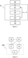
- Figure 1 shows a schematic flow diagram of an embodiment of the method for determining the component of a magnetic field H m in a predetermined direction.
- the method comprises a setup step S0.
- ⁇ 0 ⁇ , a time increment ⁇ t , a delay time period corresponding to a first iteration t 1 L and a number of iterations N are determined.
- a quantum system Q is initially prepared in its ground state.
- the method further comprises preparing the quantum system Q in the coherent superposition state
- the time period between the preparation step S1 and the readout operation in the readout step S3 is given by the delay time period t i L .
- the method further comprises determining the component of the magnetic field H m in the predetermined direction according to the outcome of the projective measurements (determination step S4).
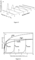
- FIG. 2 shows a schematic diagram of an embodiment of an apparatus for determining the component of a magnetic field H m in a predetermined direction.
- the apparatus comprises a quantum system Q and a control and measurement unit CM.
- the apparatus further comprises a dilution refrigerator as a refrigerating unit (not shown) configured to cool the quantum system Q into its ground state.
- the control and measurement unit CM is configured to carry out the steps of preparing the quantum system Q in the coherent superposition state
- ⁇ 0 ⁇ (preparation step S1) and letting the quantum system Q evolve for the delay time period t i L (evolution step S2) and performing a readout operation and a projective measurement on the quantum system Q (readout step S3), and iteratively repeating the preparation step S1, the evolution step S2 and the readout step S3, wherein the delay time period t i L increases linearly by the same time increment ⁇ t > 0 after each iteration, i.e., t i L t 1 L + i ⁇ 1 ⁇ t .
- the control and measurement unit CM is further configured to carry out the step of determining the component of the magnetic field H m in the predetermined direction according to the outcomes of the projective measurements (determination step S4).
- the quantum system Q is a superconducting circuit corresponding to a transmon device.
- the transmon device comprises a shunting capacitance and a superconducting loop interrupted by two Josephson junctions, wherein the superconducting loop is arranged such that it is threaded by the magnetic flux corresponding to the component of the magnetic field in the predetermined direction.
- the area of the superconducting loop is predetermined.
- the transmon device or the source of the magnetic field to be determined are arranged such that the normal vector of the superconducting loop corresponds to the predetermined direction.
- the predetermined direction corresponds to the z-direction of a Cartesian coordinate system with its origin corresponding to the geometric center of the superconducting loop.
- the transmon device couples capacitively to a transmission line resonator R.
- k ⁇ ( k ⁇ 0, 1, 2 ⁇ ).
- the qutrit states are the eigenstates of the component of the spin operator in the predetermined direction.
- the qutrit states correspond to the three projections - ⁇ , 0, ⁇ of the magnetic moment of the transmon device.
- the magnetic component ⁇ of the transmon device has been measured in advance and is thus predetermined.
- the charging energy E c is obtained from the total capacitance of the transmon device. Consequently, the energy level spacings E k , k +1 ( ⁇ ) depend identically on the reduced magnetic field ⁇ and on the component of the magnetic field H m in the predetermined direction.
- the control and measurement unit CM comprises a signal generator S.
- the signal generator S comprises an arbitrary wave generator.
- the signal generator S is configured to generate two-tone radio-frequency control pulses C 1 , C 2 , C 3 of rectangular shape for preparing the quantum system Q in the coherent superposition state
- the signal generator S is also configured to generate two-tone radio-frequency readout pulses R 1 , R 2 , R 3 of rectangular shape for performing readout operations on the quantum system Q. Additionally, the signal generator S is configured to generate probe pulses for performing projective measurements on the quantum system Q.
- the control and measurement unit CM comprises a detector D.
- the control and measurement unit CM and the detector D are configured to perform quantum non-demolition measurements on the quantum system Q.
- the control and measuring unit CM also comprises coupling means configured to couple the signal generator S with the quantum system Q (e.g., via a gate line) and with the transmission line resonator R (e.g., via a transmission line).
- the control and measuring unit CM also comprises coupling means configured to couple the detector D with the transmission line resonator (e.g., via a transmission line).
- the control and measurement unit CM comprises an electronic evaluation unit E and an electronic storage unit. The electronic storage unit is part of the electronic evaluation unit E.
- the pulse sequence comprises the control pulses C 1 , C 2 , C 3 for the preparation step S1 and the readout pulses R 1 , R 2 , R 3 for the readout operation in the readout step S3.
- the pulse sequence is brought into interaction with the quantum system Q via the coupling means connecting the signal generator S and the quantum system Q.
- the pulse durations of the control pulses C 1 , C 2 , C 3 and the readout pulses R 1 , R 2 , R 3 are considerably smaller than the delay time period t 1 L .
- the quantum system Q is configured to couple to the transmission line resonator R only dispersively.
- a resonance of the combined system (R and Q) is then probed using a probe pulse (not shown) generated by the signal generator S after a readout pulse R 1 , R 2 , R 3 .
- the probe pulse is a microwave pulse coupling to the transmission line resonator R via a transmission line. Since the transmission line resonator R is coupled to the quantum system Q, the probe pulse probes the energy spectrum of the combined system (R and Q).
- the state of the quantum system Q i.e., the measurement result of the projective measurement, is then obtained from the phase shift of the probe pulse reflected from the transmission line resonator R and measured with the detector D (dispersive readout). After each quantum non-demolition measurement, the quantum system Q relaxes again into its ground state before the next iteration starts.
- ⁇ 0 ⁇ are determined such that the coherent superposition state
- ⁇ 0 ⁇ is the eigenstate of the x-component ⁇ x (or x-projection) of the spin-operator ⁇ with the largest eigenvalue 1 in terms of its absolute value.
- ⁇ 0 ⁇ is written as a vector 1 / 2 , 1 / 2 , 1 / 2 ⁇ .
- ⁇ 0 ⁇ can be written more generally as e i ⁇ e i ⁇ / 2 , 1 / 2 , e ⁇ i ⁇ / 2 ⁇ with arbitrary real numbers ⁇ , ⁇ .
- the initial probability distribution of the component of the magnetic field is determined to be a Gaussian function P 0 ( ⁇
- ⁇ ) N ( ⁇ R , ⁇ 2 ) with a mean ⁇ R and the standard deviation ⁇ .
- the mean ⁇ R corresponds to an estimated value for the component of the magnetic field obtained from a classical measurement.
- the standard deviation ⁇ corresponds to an estimated initial determination uncertainty.
- the time increment may also be chosen differently and adapted to the requirements of an apparatus. However, the time increment should ideally not deviate more than an order of magnitude from the value ⁇ / ⁇ .
- an expected information gain is estimated and the delay time period of the first iteration t 1 L is determined according to the estimate of the expected information gain. More specifically, the delay time period of the first iteration t 1 L is determined to be the saturation time of the expected information gain corresponding to the first iteration.
- the expected information gain is determined from a simulation of the dynamical evolution of the quantum system Q during the first iteration before the first iteration is actually carried out as explained further below in more detail.
- ⁇ 1 ⁇ after the readout operation in the first iteration are calculated using a simulation of the dynamical evolution of the quantum system Q as explained further below.
- t 1 is treated as a variable for the delay time period.
- the unitary transformation matrix U 1 r ⁇ corresponds to the readout operation in the first iteration (for an explicit matrix representation see further below).
- the unitary transformation matrix U 1 p ⁇ corresponds to the preparation step S1 in the first iteration (for an explicit matrix representation see further below).
- the expected information gain corresponding to the first iteration ⁇ I 1 ⁇ is calculated.
- the expected information gain ⁇ I 1 ⁇ is calculated for different time arguments t.
- the preparation step S1 the preparing of the quantum system Q in the coherent superposition state
- ⁇ 0 ⁇ is the same in each iteration.
- the matrix elements of U ⁇ i p are obtained from the amplitudes of the coherent superposition state
- the control pulses C 1 , C 2 , C 3 feature the same control pulse frequencies in each iteration in the iteration loop IL.
- an interaction of the quantum system Q with the component of the magnetic field in the predetermined direction changes the relative phases of the state of the quantum system Q, i.e., ⁇ 0 ⁇ ⁇ i t , such that the qutrit state
- a readout operation is performed on the quantum system Q corresponding to a Fourier transform F 3 of the state of the quantum system Q.
- the readout operation corresponds to an interaction of the quantum system Q with a readout pulse R 1 , R 2 , R 3 before the projective measurement takes place.
- the readout operation corresponds to a Fourier transform of the state of the quantum system Q applied to the qutrit states
- the matrix elements of U i r are obtained from the Fourier transform F 3 and correspond to the readout pulse frequencies of a readout pulse R 1 , R 2 , R 3 .
- the readout pulses R 1 , R 2 , R 3 feature the same readout pulse frequencies in each iteration in the iteration loop IL.
- a projective measurement is performed on the quantum system Q after the readout operation.
- the projective measurement determines the state of the quantum system
- the measurement result ⁇ i is stored in the electronic storage unit after each iteration.
- the initial probability distribution is determined in the setup step S0.
- ⁇ , t n , s n ) is chosen from the probability distributions of finding the quantum system in a pure state calculated in the setup step S0 (and stored in the electronic storage unit) according to the actual outcome ⁇ n of the projective measurement.
- the time argument t n in each update corresponds to a delay time period t i L .
- the component of the magnetic field H m is obtained from the mean value of the probability distribution of the component of the magnetic field updated according to Bayes theorem according to the measurement result of the projective measurement obtained in the last iteration.
- Figure 4 shows an estimate of the expected information gain ⁇ I 1 ⁇ for different coherent superposition states and time arguments.
- An increase of the expected information gain ⁇ I 1 ⁇ then corresponds to a decrease of the width of the probability distribution of the component of the magnetic field and thus an increase of the determination accuracy.
- Figure 5 shows the probability distribution of the magnetic flux in the predetermined direction for the first 6 iterations.
- the magnetic flux corresponds to the component of the magnetic field in the predetermined direction threading the superconducting loop of the transmon device.
- the probability distribution of the magnetic flux thus corresponds to the probability distribution of the component of the magnetic field (up to a trivial variable transformation involving the predetermined area of the superconducting loop).
- the magnetic flux quantum is denoted by ⁇ 0 .
- the results of the proposed method are denoted by LAMA (with linearly increasing delay time periods).
- the LAMA method is compared with a classical protocol (with constant delay time periods), a Kitaev protocol (with exponentially increasing delay time periods) and a Fourier protocol (with exponentially decreasing delay time periods, wherein the corresponding graph in Figure 6 starts with the longest delay time period).
- the actual information gain I is obtained from the width ⁇ ( t ⁇ ) of the probability distribution of the component of the magnetic field as I ⁇ - ln ⁇ ( t ⁇ ) + ln ⁇ (0).
- the outcomes of the projective measurement are generated randomly and sampled from a probability distribution.
- the information gain shown in Figure 6 is obtained by averaging over the results of 1000 separately simulated iteration loops IL.
- the results of the proposed method (LAMA) are compared with the other protocols through simulating the operations of the latter in an analogous manner, although the number of iterations has been adapted slightly as required by the underlying algorithms.
- a coherence time T c 5 ⁇ s is predetermined.
- the results of the Fourier protocol are shown for three different choices of the delay time period in the first iteration.
- the proposed method (LAMA) provides a higher information gain already for total phase accumulation times smaller than the coherence time T c of the quantum system Q.
- FIG. 7 shows simulation results analogous to Figure 6 , but for different coherence times T c .
- the Kitaev protocol approaches the Heisenberg limit for total phase accumulation times t ⁇ smaller than the coherence time T c , but the scaling exponent almost drops to zero when the total phase accumulation time t ⁇ approaches the coherence time T c .
- the proposed method (LAMA) becomes much more efficient when the total phase accumulation time t ⁇ approaches the coherence time T C
- the proposed method (LAMA) becomes much more efficient when the total phase accumulation time t ⁇ becomes on the order of the coherence time T C and larger.
- a finite coherence time T C does not pose any notable limitation on the efficiency of the proposed method (LAMA) until the delay time period becomes comparable to the coherence time T C .
Landscapes
- Engineering & Computer Science (AREA)
- Physics & Mathematics (AREA)
- General Physics & Mathematics (AREA)
- Theoretical Computer Science (AREA)
- Data Mining & Analysis (AREA)
- Mathematical Physics (AREA)
- Computational Mathematics (AREA)
- Mathematical Analysis (AREA)
- Mathematical Optimization (AREA)
- Pure & Applied Mathematics (AREA)
- Condensed Matter Physics & Semiconductors (AREA)
- General Engineering & Computer Science (AREA)
- Software Systems (AREA)
- Computing Systems (AREA)
- Evolutionary Computation (AREA)
- Artificial Intelligence (AREA)
- Algebra (AREA)
- Probability & Statistics with Applications (AREA)
- Databases & Information Systems (AREA)
- Bioinformatics & Computational Biology (AREA)
- Evolutionary Biology (AREA)
- Operations Research (AREA)
- Bioinformatics & Cheminformatics (AREA)
- Life Sciences & Earth Sciences (AREA)
- Measuring Magnetic Variables (AREA)
- Superconductor Devices And Manufacturing Methods Thereof (AREA)
Description
- The invention relates to a method, apparatus and computer program product for determining the component of a magnetic field in a predetermined direction.
- In classical metrology, a method for determining a magnetic field value typically involves several independent measurements. Thereby, the scaling behaviour of the determination uncertainty is given by the standard quantum limit (or shot noise limit) δx ∝ 1/Rα with α=1/2, where R denotes a measure for the required resources, e.g., the number of measurements, a characteristic measurement time or a characteristic measurement energy. However, it is conjectured that in the framework of quantum metrology the standard quantum limit can be overcome and the precision of the method can be improved considerably using quantum resources.
- For example, phase estimation protocols have been proposed based on the Fourier algorithm or the Kitaev algorithm for achieving the fundamental Heisenberg scaling limit of quantum metrology with the scaling exponent α=1.
- According to these protocols a sequence of Ramsey experiments is carried out which, however, requires a delicate fine-tuning of various parameters for each experiment in the sequence.
- Moreover, protocols based on the Fourier and Kitaev algorithm are optimized for the determination of discrete magnetic fields, wherein at least one component of the magnetic field can only take on discrete values. Furthermore, the Ramsey delay time in each Ramsey experiment shows an exponential scaling behaviour within the sequence. Therefore, a practical application of such protocols is strongly limited in the relevant situation, where the magnetic field strength may be continuously distributed and the quantum system suffers from dephasing and decoherence.
- The following references are provided:
- [R1] S. Danilin et al, "Quantum-enhanced magnetometry by phase estimation algorithms with a single artificial atom", NPJ QUANTUM INFORMATION, vol. 4, no. 1, 29 June 2018 (2018-06-29), DOI: 10.1038/s41534-018-0078-y
- [R2] C.L. Degen et al: "Quantum Sensing", REVIEWS OF MODERN PHYSICS, vol. 89, no. 3, 1 July 2017 (2017-07-01), DOI: 10.1103/RevModPhys.89.035002
- Document R1 describes modified Fourier and Kitaev algorithms that are used to determine magnetic fields using a superconducting transmon circuit as a probe. Document R2 provides a review on quantum sensing.
- Thus, an object of the invention is to overcome such limitations and provide a simple and practical method, apparatus and computer program product for determining magnetic fields with high precision.
- This object of the invention is achieved by the method, apparatus and computer program product as described in
claims 1, 7 and 13. Advantageous developments and embodiments are described in the dependent claims. - The invention relates to a method for determining the component of a magnetic field in a predetermined direction. The method comprises preparing a quantum system in a coherent superposition state, wherein the coherent superposition state is the same in each iteration and/or the coherent superposition state corresponds to an unbalanced superposition of at least three states with respective amplitudes and/or the coherent superposition state corresponds to the maximum modulus spin-projection in a direction perpendicular to the predetermined direction; (preparation step), letting the quantum system evolve for a delay time period, wherein the quantum system interacts with the magnetic field in the predetermined direction, wherein the interaction with the quantum system changes the relative phases of the coherent superposition state of the quantum system and an accumulated phase depends on the component of the magnetic field in the predetermined direction Revolution step), and performing a readout operation and a projective measurement on the quantum system wherein the projective measurement corresponds to a measurement of the spin polarization of the quantum system in the predetermined direction, (readout step). The preparation step, the evolution step and the readout step are iteratively repeated in an iteration loop, wherein the delay time period increases linearly by the same time increment after each iteration. The method further comprises determining the component of the magnetic field in the predetermined direction according to the outcome of the projective measurements (determination step).
- The steps of the method are carried out by a control and measurement unit. The proposed method allows determining the component of a magnetic field with high precision. Thereby, the preparation of the quantum system in a coherent superposition state and the linear increase of the delay time period after each iteration ensures the quantum advantage compared to classical metrological protocols. Moreover, since the delay time period increases only linearly, a large number of iterations and a large total phase accumulation time can be realized. Consequently, a high determination accuracy can be achieved and the proposed method can be carried out efficiently even in the case of continuous magnetic fields and in the presence of dissipation and decoherence. Moreover, the proposed method is far less complex and requires less experimental and computational resources. In particular, the delay time periods of the iteration loop may be predetermined.
- The origin or source of the magnetic field to be determined may be known and the predetermined direction may be chosen accordingly. For example, the electromagnetic radiation characteristics of the origin or source may be known in advance and the predetermined direction may be chosen according to the electromagnetic radiation characteristics.
- Preferably, the coherent superposition state is the same in each iteration of the iteration loop. In particular, the coherent superposition state may be prepared identically in each preparation step, e.g., by using the same control pulse frequencies in each iteration. For that purpose, the quantum system may be initialized in the ground state before each iteration of the preparation step. For example, the quantum system may be cooled into the ground state after each projective measurement. The quantum system may also be forced into the ground state after each projective measurement on a short time scale using a reset operation carried out before the next iteration starts in the iteration loop.
- In the preparation step, the preparing of the quantum system in the coherent superposition state may be achieved using a control pulse, e.g., generated by a signal generator. The coherent superposition state may be the eigenstate of a component of the spin operator in a direction perpendicular to the predetermined direction with the largest eigenvalue in terms of its absolute value. Preferably, the coherent superposition state corresponds to the maximum modulus spin-projection in a direction perpendicular to the predetermined direction. Preparing the quantum system in such a coherent superposition state allows determining the component of the magnetic field with high precision in a large measurement range.
- Most preferably, the coherent superposition state may correspond to an unbalanced superposition of at least three states with respective amplitudes. Thereby, at least two amplitudes may differ from one another in terms of their absolute value. A coherent superposition state composed of a large number of pure states allows utilizing a larger spin projection in the predetermined direction and may further improve the sensitivity of the quantum system.
- The evolution step comprises an interaction of the quantum system with the magnetic field in the predetermined direction. In the evolution step, a phase associated with each pure state forming the coherent superposition state accumulates during the delay time period. Thereby, the accumulated phase depends on the component of the magnetic field in the predetermined direction.
- Preferably, the readout operation corresponds to a Fourier transform of the state of the quantum system. The readout operation may be performed on the quantum system before the projective measurement is carried out. Specifically, the readout operation may be performed using a readout pulse, e.g., generated by the signal generator. Preferably, the readout operation is carried out identically in each iteration, e.g., by using the same readout pulse frequencies in each iteration.
- The projective measurement corresponds to a measurement of the spin polarization of the quantum system in the predetermined direction. Correspondingly, a measurement result of the projective measurement may be a component of the spin of the quantum system in the predetermined direction. Preferably, the projective measurement determines a pure state of the quantum system after the readout operation. Thereby, the pure state corresponds to one of the states forming the coherent superposition state. The projective measurement of the quantum system may be performed using a probe pulse, e.g., generated by the signal generator. Preferably, the projective measurement is a quantum non-demolition measurement.
- The number of iterations in the iteration loop may be predetermined. The number of iterations may be at least three. Preferably, the number of iterations is at least 20. Most preferably, the number of iterations is at least 50. The iteration loop may also terminate when a desired determination accuracy is achieved. The desired determination accuracy may be compared to an inverse of the width of a probability distribution of the component of the magnetic field that is determined or updated after each iteration. For that purpose, at least part of the determination step may be iteratively repeated inside the iteration loop.
- The number of iterations may be determined such that the iteration loop terminates when a delay time period becomes larger than a coherence time of the quantum system. The number of iterations may also be determined such that the iteration loop terminates when the total phase accumulation time becomes larger than the coherence time of the quantum system, preferably larger than at least three times a coherence time of the quantum system, most preferably larger than at least ten times a coherence time of the quantum system. The total phase accumulation time may be defined as the sum of the delay time periods of all iterations in the iteration loop.
- The method may further comprise estimating an initial determination uncertainty for the component of the magnetic field in the predetermined direction. The time increment may be determined according to the initial determination uncertainty. Specifically, the time increment may correspond to the inverse of the initial determination uncertainty.
- The method may further comprise determining an initial probability distribution of the component of the magnetic field. The initial probability distribution may be determined as a constant or a uniform distribution (over a large range of magnetic fields), e.g. in the absence of prior knowledge about the component of the magnetic field. The initial probability distribution may also be determined to be a Gaussian function. The mean of the Gaussian function may correspond to an estimated value for the component of the magnetic field. The standard deviation of the Gaussian function may correspond to the estimate of the initial determination uncertainty.
- The estimated value for the component of the magnetic field and the estimated initial determination uncertainty may reflect the state of knowledge about the magnetic field before the first iteration of the iteration loop is actually carried out. Exemplary, the estimated value for the component of the magnetic field and the estimated initial determination uncertainty may be obtained in advance from a classical measurement protocol or from a numerical simulation or from an analytic argument.
- The method may further comprise estimating an expected information gain. Preferably, the delay time period of the first iteration is determined according to the estimate of the expected information gain. The estimate of the expected information gain may correspond to the expected information gain after the first iteration. Thereby, the information gain may be defined to correspond to a measure for the gain in knowledge about the component of the magnetic field in the predetermined direction obtained from a projective measurement. The expected information gain may be estimated according to a simulation of the dynamical evolution of the quantum system using a Hamiltonian and/or a Lindblad master equation (see further below). The delay time period of the first iteration in the iteration loop may then be determined as the saturation time of the information gain expected from the projective measurement in the first iteration.
- The component of the magnetic field may be determined using a Bayesian learning algorithm. Preferably, for each iteration a probability distribution of the component of the magnetic field may be updated according to Bayes theorem. For the first iteration, an update of the initial probability distribution may be determined. An update may comprise multiplying a probability distribution of the component of the magnetic field with a probability distribution of finding the quantum system in a pure state after the readout operation. The probability distribution of finding the quantum system in a pure state after the readout operation used in the update may be chosen/selected according to the outcome of the projective measurement from a set of predetermined (calculated) probability distributions obtained from a simulation of the dynamical evolution of the quantum system (see further below). In other words, the outcome of a projective measurement determines which one of the predetermined probability distributions of finding the quantum system in a pure state is used in the update.
- The width of the probability distribution of the component of the magnetic field may correspond to the determination uncertainty of the proposed method. By updating the probability distribution of the component of the magnetic field using Bayes theorem, the determination uncertainty may decrease from iteration to iteration reflecting the information gain obtained after each iteration and reflecting an increase of the determination accuracy. In particular, the component of the magnetic field may be determined from an update of the probability distribution of the component of the magnetic field after the last iteration in the iteration loop. In particular, the component of the magnetic field may be determined as the mean value of the probability distribution of the component of the magnetic field updated according to Bayes theorem after the last iteration in the iteration loop.
- The method may further comprise simulating a dynamical evolution of the quantum system using a Lindblad master equation. The Lindblad master equation may constitute a model for the incoherent dynamics of the quantum system. The Lindblad master equation may comprise a decoherence rate and/or distributions may be calculated as a function of the component of a (reference) magnetic field in the predetermined direction (treated as a variable). The probability distributions may be determined for each pure state forming the coherent superposition state and may be stored electronically as a function or algebraic expression in an electronic storage unit.
- With the simulation of the dynamical evolution of the quantum system as outlined above, the expected information can be estimated and the delay time period of the first iteration can be determined. Moreover, a set of probability distributions of finding the quantum system in a pure state after the readout operation can be calculated and used in the Bayesian learning algorithm in order to update the probability distribution of the magnetic field.
- With the proposed method the Heisenberg scaling limit can be reached for a total phase accumulation time comparable to the coherence time of the quantum system. A large number of iterations can be realized in practice and the component of the magnetic field can be determined with high precision. In particular, a finite coherence time does not pose a stringent limitation to the efficiency of the proposed method until the delay time period of the last iteration becomes comparable to the coherence time.
- The invention also relates to an apparatus for determining the component of a magnetic field in a predetermined direction. The apparatus comprises a quantum system and a control and measurement unit.
- The control and measurement unit is configured to carry out the steps of preparing the quantum system in a coherent superposition state, wherein the coherent superposition state is the same in each iteration and/or the coherent superposition state corresponds to an unbalanced superposition of at least three states with respective amplitudes and/or the coherent superposition state corresponds to the maximum modulus spin-projection in a direction perpendicular to the predetermined direction; (preparation step) and letting the quantum system evolve for a delay time period, wherein the quantum system interacts with the magnetic field in the predetermined direction, wherein the interaction with the quantum system changes the relative phases of the coherent superposition state of the quantum system and an accumulated phase depends on the component of the magnetic field in the predetermined direction (evolution step), and performing a readout operation and a projec-tive measurement on the quantum system, wherein the projective measurement corresponds to a measurement of the spin polarization of the quantum system in the predetermined direction (readout step), and iteratively repeating the preparation step, the evolution step and the readout step, wherein the delay time period increases linearly by the same time increment after each iteration. The control and measurement unit is further configured to carry out the step of determining the component of the magnetic field in the predetermined direction according to the outcomes of the projective measurements.
- The quantum system may correspond to a qubit or a d-dimensional qudit with d>2. The qubit or qudit states may form the computational basis and may correspond to the eigenstates of the component of the spin operator in the predetermined direction, wherein the spin may correspond to the magnetic moment of the quantum system. In particular, the magnetic moment of the quantum system may be the coupling constant of the quantum system interacting with the magnetic field in the predetermined direction. The qubit or qudit states may be energy eigenstates of the quantum system. More specifically, the quantum system may correspond to a qutrit, i.e., a qudit with d=3. The three qutrit states may then correspond, respectively, to the three components of the magnetic moment of the quantum system projected on the predetermined direction.
- Preferably, the quantum system comprises an experimentally controllable energy spectrum, wherein the energy level spacings in at least a part of the energy spectrum depend identically on the component of the magnetic field in the predetermined direction. From said part of the energy spectrum the states forming the coherent superposition state, e.g., the qudit states, may be chosen as the computational basis. Here, an identical dependency may mean that the energy level spacings as a function of the component of the magnetic field in the predetermined direction are shifted with respect to each other by a constant energy shift. In particular, the constant energy shift does not depend on the component of the magnetic field. This may ensure linear phase accumulation dynamics.
- The quantum system may be a superconducting circuit. More specifically, the quantum system may comprise at least one transmon device, a charge qudit and/or a flux qudit. Alternatively, the quantum system may comprise a single atom in a trap or a single ion in a trap, a single semiconductor quantum dot, a photon or polariton inside a resonator or waveguide, or a Nitrogen-vacancy center in diamond.
- The control and measurement unit may further comprise at least one signal generator configured to generate control pulses for preparing the quantum system in the coherent superposition state. The signal generator may also be configured to generate readout pulses for performing readout operations on the quantum system. The signal generator may also be configured to generate probe pulses for performing projective measurements on the quantum system. Specifically, the signal generator may comprise an arbitrary wave generator. The control pulses and readout pulses may be multi-tone pulses.
- The control and measuring unit may also comprise coupling means, e.g., configured to couple the signal generator with the quantum system. The control pulses or the readout pulses may interact with the quantum system directly via such coupling means. The probe pulses may interact with the quantum system indirectly via such coupling means. For example, the coupling means may comprise a transmission line, a transmission line resonator, a gate or a flux line. The control and measurement unit may further comprise at least one detector or a detector unit. The at least one detector or detector unit may also be coupled to the quantum system. Preferably, the control and measurement unit is configured to perform quantum non-demolition measurements on the quantum system.
- The control and measurement unit may further comprise a computing unit, an electronic evaluation unit and/or an electronic storage unit. The electronic storage unit may be part of the computing or the electronic evaluation unit. The electronic evaluation unit may be part of the computing unit. The computing unit or the electronic evaluation unit may comprise at least one of a processor, a CPU (central processing unit), a GPU (graphical processing unit). The computing unit may also be remotely connected to the evaluation unit. The computing unit or the evaluation unit may also be remotely connected to the control and measurement unit.
- The invention is also related to a computer program product comprising a computer program (or a sequence of instructions) using software means for performing the method for determining the component of a magnetic field in a predetermined direction, when the computer program runs in a computing unit. At least parts of the computer program can be formulated in a script language or a compiler language. The computer program can be stored directly stored in an internal memory, a memory unit or the data storage unit of the evaluation unit. The computer program product can be stored in machine-readable data carriers, preferably digital storage media.
- In summary, a simple and practical method, apparatus and computer program product for determining magnetic fields with remarkable sensitivity and precision are established. In particular, a near Heisenberg scaling can be achieved in situations where known metrological procedures become ineffective. Thereby, a component of a magnetic field can be determined with high precision using only modest computational and hardware resources.
- The invention may find applications in a wide range of technology. Exemplary, the invention may be used to determine magnetic fields originating from single atoms and ions, biological probes or quantum engineered systems, e.g., embedded in a quantum computer or quantum simulator.
- Exemplary embodiments of the invention are illustrated in the drawings and will now be described with reference to
figures 1 to 7 . - In the figures:
- Fig. 1
- shows a schematic flow diagram of an embodiment of the method,
- Fig. 2
- shows a schematic diagram of an embodiment of the apparatus,
- Fig. 3
- shows an exemplary pulse sequence corresponding to three iterations,
- Fig. 4
- shows an exemplary estimate of the expected information gain,
- Fig. 5
- shows exemplary updates of a probability distribution in the iteration loop,
- Fig. 6
- shows a comparison of the information gain obtained from different methods,
- Fig. 7
- shows the scaling behaviour of different methods.
-
Figure 1 shows a schematic flow diagram of an embodiment of the method for determining the component of a magnetic field Hm in a predetermined direction. - The method comprises a setup step S0. In the setup step S0, a coherent superposition state |ψ 0〉, a time increment Δt, a delay time period corresponding to a first iteration

- The method further comprises preparing the quantum system Q in the coherent superposition state |ψ 0〉 (preparation step S1), letting the quantum system Q evolve for the delay time period


- The method further comprises determining the component of the magnetic field Hm in the predetermined direction according to the outcome of the projective measurements (determination step S4).
-
Figure 2 shows a schematic diagram of an embodiment of an apparatus for determining the component of a magnetic field Hm in a predetermined direction. The apparatus comprises a quantum system Q and a control and measurement unit CM. The apparatus further comprises a dilution refrigerator as a refrigerating unit (not shown) configured to cool the quantum system Q into its ground state. - The control and measurement unit CM is configured to carry out the steps of preparing the quantum system Q in the coherent superposition state |ψ 0〉 (preparation step S1) and letting the quantum system Q evolve for the delay time period


- In an exemplary embodiment, the quantum system Q is a superconducting circuit corresponding to a transmon device. The transmon device comprises a shunting capacitance and a superconducting loop interrupted by two Josephson junctions, wherein the superconducting loop is arranged such that it is threaded by the magnetic flux corresponding to the component of the magnetic field in the predetermined direction. The area of the superconducting loop is predetermined. The transmon device or the source of the magnetic field to be determined are arranged such that the normal vector of the superconducting loop corresponds to the predetermined direction. In the following, the predetermined direction corresponds to the z-direction of a Cartesian coordinate system with its origin corresponding to the geometric center of the superconducting loop. Additionally, the transmon device couples capacitively to a transmission line resonator R.
- The quantum system Q is described by a qutrit (d=3) with three experimentally controllable states |k〉 (k = {0, 1, 2}). The qutrit states are the eigenstates of the component of the spin operator in the predetermined direction. Thus, the qutrit states correspond to the three projections -µ, 0, µ of the magnetic moment of the transmon device. Here, the magnetic component µ of the transmon device has been measured in advance and is thus predetermined.
- The Hamiltonian of the quantum system Q is given by


- The control and measurement unit CM comprises a signal generator S. The signal generator S comprises an arbitrary wave generator. The signal generator S is configured to generate two-tone radio-frequency control pulses C1, C2, C3 of rectangular shape for preparing the quantum system Q in the coherent superposition state |ψ 0〉. The signal generator S is also configured to generate two-tone radio-frequency readout pulses R1, R2, R3 of rectangular shape for performing readout operations on the quantum system Q. Additionally, the signal generator S is configured to generate probe pulses for performing projective measurements on the quantum system Q.
- The control and measurement unit CM comprises a detector D. The control and measurement unit CM and the detector D are configured to perform quantum non-demolition measurements on the quantum system Q. The control and measuring unit CM also comprises coupling means configured to couple the signal generator S with the quantum system Q (e.g., via a gate line) and with the transmission line resonator R (e.g., via a transmission line). The control and measuring unit CM also comprises coupling means configured to couple the detector D with the transmission line resonator (e.g., via a transmission line). Moreover, the control and measurement unit CM comprises an electronic evaluation unit E and an electronic storage unit. The electronic storage unit is part of the electronic evaluation unit E.
-
Figure 3 shows a pulse sequence generated by the signal generator S for the first three iterations (i = 1, 2, 3) in the iteration loop IL. The pulse sequence comprises the control pulses C1, C2, C3 for the preparation step S1 and the readout pulses R1, R2, R3 for the readout operation in the readout step S3. The pulse sequence is brought into interaction with the quantum system Q via the coupling means connecting the signal generator S and the quantum system Q. The pulse durations of the control pulses C1, C2, C3 and the readout pulses R1, R2, R3 are considerably smaller than the delay time period


- For the purpose of performing a quantum non-demolition measurement on the quantum system Q, the quantum system Q is configured to couple to the transmission line resonator R only dispersively. A resonance of the combined system (R and Q) is then probed using a probe pulse (not shown) generated by the signal generator S after a readout pulse R1, R2, R3. The probe pulse is a microwave pulse coupling to the transmission line resonator R via a transmission line. Since the transmission line resonator R is coupled to the quantum system Q, the probe pulse probes the energy spectrum of the combined system (R and Q). The state of the quantum system Q, i.e., the measurement result of the projective measurement, is then obtained from the phase shift of the probe pulse reflected from the transmission line resonator R and measured with the detector D (dispersive readout). After each quantum non-demolition measurement, the quantum system Q relaxes again into its ground state before the next iteration starts.
- In the following, further details and exemplary embodiments are provided:
In the setup step S0, the amplitudes of the coherent superposition state |ψ 0〉 are determined such that the coherent superposition state |ψ 0〉 corresponds to the maximum modulus spin-projection in the x-direction perpendicular to the predetermined z-direction. Specifically, the coherent superposition state is given by
largest eigenvalue 1 in terms of its absolute value. In the qutrit basis the coherent superposition state |ψ 0〉 is written as avector 

- In the setup step S0, the initial probability distribution of the component of the magnetic field is determined to be a Gaussian function P 0(ω|Ø) = N(ωR, σ 2) with a mean ωR and the standard deviation σ. The mean ωR corresponds to an estimated value for the component of the magnetic field obtained from a classical measurement. The standard deviation σ corresponds to an estimated initial determination uncertainty. The time increment Δt is obtained from the inverse of the estimated initial determination uncertainty σ as Δt = π/σ. In an alternative embodiment, the time increment may also be chosen differently and adapted to the requirements of an apparatus. However, the time increment should ideally not deviate more than an order of magnitude from the value π/σ.
- In the setup step S0, an expected information gain is estimated and the delay time period of the first iteration


- In general terms, the information gain ΔI n+1 is defined as a decrease in entropy ΔI n+1 = Sn -S n+1 with n = 0,.., N - 1. Thereby, the entropy is given by the Shannon entropy in terms of a probability distribution


- For n = 0, the probability distribution


- In the setup step S0, the probability distributions P(ξ̃ 1|ω, t 1, s 1) of finding the quantum system Q in the pure state |ξ̃ 1〉 after the readout operation in the first iteration are calculated using a simulation of the dynamical evolution of the quantum system Q as explained further below. The corresponding algebraic expressions for the probability distributions are electronically stored in the electronic storage unit as a function of the reduced magnetic field (treated as a variable) for all possible pure states ξ̃ 1 = {0, 1, 2}.
- More specifically, the dynamical evolution of the quantum system Q is simulated using a Lindblad master equation for the density matrix p̂ of the quantum system Q, i.e.,




- The probability distributions P(ξ̃ 1|ω, t 1, s 1) are then obtained from


- In an alternative embodiment, the probability distribution P(ξ̃ 1|ω, t 1, s 1) are obtained from a simulation using the Hamiltonian for the coherent dynamics of the quantum system Q, i.e.,



- Since the outcome of a projective measurement is not known before an iteration is actually carried out, the expected information gain 〈ΔI n+1〉 is defined in terms of an average over all possible outcomes ξ̃ n+1, i.e.,


- In the setup step S0, the expected information gain corresponding to the first iteration 〈ΔI 1〉 is calculated. The integral over the reduced magnetic field variable is estimated using a discretization with respect to the reduced magnetic field corresponding to an evenly spaced grid ωm with m = 1,.., M and M = 105 points according to


- Using these expression, the expected information gain 〈ΔI 1〉 is calculated for different time arguments t. In the setup step S0, the delay time period


- In an alternative embodiment, and for the quantum system Q corresponding to a qutrit, the delay time period


- In the preparation step S1, the preparing of the quantum system Q in the coherent superposition state |ψ 0〉 is achieved using a control pulse C1, C2, C3 interacting with the quantum system Q. In the iteration loop IL, the coherent superposition state |ψ 0〉 is the same in each iteration. Specifically, the preparation step S1 corresponds to a
unitary transformation 

- The matrix elements of

- In the evolution step S2, the quantum system Q evolves dynamically for a time given by the delay time period


0 ωti |k〉 during a time
- In the readout step S3, a readout operation is performed on the quantum system Q corresponding to a Fourier transform F 3 of the state of the quantum system Q. In each iteration, the same readout operation is performed. The readout operation corresponds to an interaction of the quantum system Q with a readout pulse R1, R2, R3 before the projective measurement takes place. Specifically, the readout operation corresponds to a Fourier transform of the state of the quantum system Q applied to the qutrit states |n〉 with n = {0, 1, 2}, i.e.,



- The matrix elements of

- In the readout step S3, a projective measurement is performed on the quantum system Q after the readout operation. The projective measurement determines the state of the quantum system |ξi 〉. The measurement result ξi is stored in the electronic storage unit after each iteration.
- In the determination step S4, the component of the magnetic field Hm is determined using a Bayesian learning algorithm. Specifically, the probability distribution of the component of the magnetic field is updated according to Bayes theorem for each iteration

- The initial probability distribution is determined in the setup step S0. In each update, the probability distribution P(ξn |ω, tn, s n ) is chosen from the probability distributions of finding the quantum system in a pure state calculated in the setup step S0 (and stored in the electronic storage unit) according to the actual outcome ξn of the projective measurement. The time argument tn in each update corresponds to a delay time period

-
Figure 4 shows an estimate of the expected information gain 〈ΔI 1〉 for different coherent superposition states and time arguments. Here, ωR = 0, σ = 2π/(90ns) and D 0 = 1. The saturation time of the expected information gain is Ts = 15 ns. Accordingly, the delay time period of the first iteration is
figure 4 , the unbalanced coherentsuperposition state 
superposition state 


-
Figure 5 shows the probability distribution of the magnetic flux in the predetermined direction for the first 6 iterations. The magnetic flux corresponds to the component of the magnetic field in the predetermined direction threading the superconducting loop of the transmon device. The probability distribution of the magnetic flux thus corresponds to the probability distribution of the component of the magnetic field (up to a trivial variable transformation involving the predetermined area of the superconducting loop). Infigure 5 , the magnetic flux quantum is denoted by φ 0. -
Figure 6 shows a simulation of the information gain as a function of the total phase accumulation time

Figure 6 starts with the longest delay time period). The maximal number of iterations considered is N = 50. InFigure 6 , the actual information gain I is obtained from the width δω(tφ ) of the probability distribution of the component of the magnetic field as I ≅ - ln δω(tφ ) + ln δω(0). InFigure 6 , the outcomes of the projective measurement are generated randomly and sampled from a probability distribution. The information gain shown inFigure 6 is obtained by averaging over the results of 1000 separately simulated iteration loops IL. The results of the proposed method (LAMA) are compared with the other protocols through simulating the operations of the latter in an analogous manner, although the number of iterations has been adapted slightly as required by the underlying algorithms. InFigure 6 , a coherence time Tc = 5 µs is predetermined. The results of the Fourier protocol are shown for three different choices of the delay time period in the first iteration. Clearly, the proposed method (LAMA) provides a higher information gain already for total phase accumulation times smaller than the coherence time Tc of the quantum system Q. -
Figure 7 shows simulation results analogous toFigure 6 , but for different coherence times Tc. The scaling behaviour of the proposed method (LAMA) for Tc = 5 µs (filled circles) is compared with the Kitaev protocol for Tc = 5 µs (empty circles), Tc = 10 µs (empty squares) and Tc = 30 µs (empty triangles) on a lin-log plot. The scaling exponent α is obtained from fitting the dependence of the width δω(tφ ) of the probability distribution of the component of the magnetic field on the total phase accumulation time tφ , i.e., δω(tφ ) = 1/(tφ )α. As shown inFigure 7 , the Kitaev protocol approaches the Heisenberg limit for total phase accumulation times tφ smaller than the coherence time Tc , but the scaling exponent almost drops to zero when the total phase accumulation time tφ approaches the coherence time Tc . On the contrary, the proposed method (LAMA) becomes much more efficient when the total phase accumulation time tφ approaches the coherence time TC On the contrary, the proposed method (LAMA) becomes much more efficient when the total phase accumulation time tφ becomes on the order of the coherence time TC and larger. In fact, a finite coherence time TC does not pose any notable limitation on the efficiency of the proposed method (LAMA) until the delay time period becomes comparable to the coherence time TC .
Claims (13)
- A method for determining the component of a magnetic field in a predetermined direction, comprising the steps of:(S1) preparing a quantum system (Q) in a coherent superposition state, wherein the coherent superposition state is the same in each iteration and/or the coherent superposition state corresponds to an unbalanced superposition of at least three states with respective amplitudes and/or the coherent superposition state corresponds to the maximum modulus spin-projection in a direction perpendicular to the predetermined direction;(S2) letting the quantum system (Q) evolve for a delay time period, wherein the quantum system (Q) interacts with the magnetic field in the predetermined direction, wherein the interaction with the quantum system (Q) changes the relative phases of the coherent superposition state of the quantum system (Q) and an accumulated phase depends on the component of the magnetic field in the predetermined direction,(S3) performing a readout operation and a projective measurement on the quantum system (Q), wherein the projective measurement corresponds to a measurement of the spin polarization of the quantum system (Q) in the predetermined direction, and iteratively repeating steps (S1), (S2) and (S3) in an iteration loop (IL),(S4) determining the component of the magnetic field in the predetermined direction according to the outcomes of the projective measurements, whereinthe steps of the method are carried out by a control and measurement unit (CM); and characterized in thatthe delay time period increases linearly by the same time increment after each iteration.
- The method according to claim 1, characterized in that the readout operation corresponds to a Fourier transform of the state of the quantum system (Q).
- The method according to one of the previous claims, characterized in that the number of iterations is predetermined and/or the number of iterations is determined such that the iteration loop terminates when a delay time period becomes larger than a coherence time of the quantum system (Q) and/or the number of iterations is determined such that the total phase accumulation time is larger than at least three times a coherence time of the quantum system (Q).
- The method according to one of the previous claims, characterized in that the method further comprises simulating a dynamical evolution of the quantum system (Q) using a Hamiltonian and/or a Lindblad master equation and estimating an expected information gain after a first iteration of the iteration loop (IL) according to the simulation of the dynamical evolution of the quantum system (Q), and determining the delay time period of the first iteration according to the estimate of the expected information gain.
- The method according to one of the previous claims, characterized in that the method further comprises estimating an initial determination uncertainty for the component of the magnetic field in the predetermined direction and determining the time increment according to the estimate of the initial determination uncertainty.
- The method according to one of the previous claims, characterized in that the component of the magnetic field is determined using a Bayesian learning algorithm and/or for each iteration a probability distribution of the component of the magnetic field is updated according to Bayes theorem using a predetermined probability distribution of finding the quantum system (Q) in a pure state according to the outcome of the projective measurement and/or the component of the magnetic field is determined from the probability distribution of the component of the magnetic field updated according to Bayes theorem using the result of the projective measurement in the last iteration.
- An apparatus for determining the component of a magnetic field in a predetermined direction, comprising a quantum system (Q) and a control and measurement unit (CM), wherein the control and measurement unit (CM) is configured to carry out the steps of (S1) preparing the quantum system (Q) in a coherent superposition state, wherein the coherent superposition state is the same in each iteration and/or the coherent superposition state corresponds to an unbalanced superposition of at least three states with respective amplitudes and/or the coherent superposition state corresponds to the maximum modulus spin-projection in a direction perpendicular to the predetermined direction; and (S2) letting the quantum system (Q) evolve for a delay time period, wherein the quantum system (Q) interacts with the magnetic field in the predetermined direction, wherein the interaction with the quantum system (Q) changes the relative phases of the coherent superposition state of the quantum system (Q) and an accumulated phase depends on the component of the magnetic field in the predetermined direction, and (S3) performing a readout operation and a projective measurement on the quantum system (Q), wherein the projective measurement corresponds to a measurement of the spin polarization of the quantum system (Q) in the predetermined direction, and iteratively repeating steps (S1), (S2) and (S3), wherein the control and measurement unit (CM) is further configured to carry out the step of (S4) determining the component of the magnetic field in the predetermined direction according to the outcomes of the projective measurements; and characterized in that
the delay time period increases linearly by the same time increment after each iteration. - The apparatus according to claim 7, characterized in that the quantum system (Q) corresponds to a d-dimensional qudit with d>2 and/or the quantum system (Q) comprises an experimentally controllable energy spectrum, wherein the energy level spacings in at least a part of the energy spectrum depend identically on the component of the magnetic field in the predetermined direction and/or the quantum system (Q) is a superconducting circuit.
- The apparatus according to claim 7 or 8, characterized in that the control and measurement unit (CM) further comprises at least one signal generator (S) configured to generate control pulses (C1, C2, C3) for preparing the quantum system (Q) in the coherent superposition state and/or readout pulses (R1, R2, R3) for performing readout operations on the quantum system (Q) and/or probe pulses for performing projective measurements on the quantum system (Q).
- The apparatus according to claim 7, 8 or 9, characterized in that the control and measurement unit (CM) further comprises at least one detector (D) and/or is configured to perform quantum non-demolition measurements on the quantum system (Q).
- The apparatus according to claims 7, 8, 9 or 10, characterized in that the control and measurement unit (CM) further comprises a computing unit and/or an electronic evaluation unit (E) and/or an electronic storage unit.
- The apparatus according to claim 7, 8, 9, 10 or 11, characterized in that the apparatus further comprises a refrigeration unit configured to cool the quantum system (Q) into its ground state.
- A computer program product comprising computer-readable instructions for performing a method according to one of the claims 1 to 6, when the computer program runs in a computing unit.
Priority Applications (6)
| Application Number | Priority Date | Filing Date | Title |
|---|---|---|---|
| EP20165571.9A EP3886003B8 (en) | 2020-03-25 | 2020-03-25 | Method, apparatus and computer program product for determining the component of a magnetic field in a predetermined direction |
| AU2021201695A AU2021201695B2 (en) | 2020-03-25 | 2021-03-17 | Method, apparatus and computer program product for determining the component of a magnetic field in a predetermined direction |
| JP2021050027A JP7250836B2 (en) | 2020-03-25 | 2021-03-24 | Methods, apparatus, and computer program products for determining components of a magnetic field in a given direction |
| KR1020210037727A KR102958682B1 (en) | 2020-03-25 | 2021-03-24 | Method, apparatus and computer program product for determining the component of a magnetic field in a predetermined direction |
| US17/211,369 US11977954B2 (en) | 2020-03-25 | 2021-03-24 | Method, apparatus and computer program product for determining the component of a magnetic field in a predetermined direction |
| CN202110322238.6A CN113449870B (en) | 2020-03-25 | 2021-03-25 | Method, device and computer program product for determining a component of a magnetic field in a predetermined direction |
Applications Claiming Priority (1)
| Application Number | Priority Date | Filing Date | Title |
|---|---|---|---|
| EP20165571.9A EP3886003B8 (en) | 2020-03-25 | 2020-03-25 | Method, apparatus and computer program product for determining the component of a magnetic field in a predetermined direction |
Publications (4)
| Publication Number | Publication Date |
|---|---|
| EP3886003A1 EP3886003A1 (en) | 2021-09-29 |
| EP3886003C0 EP3886003C0 (en) | 2024-12-04 |
| EP3886003B1 true EP3886003B1 (en) | 2024-12-04 |
| EP3886003B8 EP3886003B8 (en) | 2025-02-19 |
Family
ID=70008320
Family Applications (1)
| Application Number | Title | Priority Date | Filing Date |
|---|---|---|---|
| EP20165571.9A Active EP3886003B8 (en) | 2020-03-25 | 2020-03-25 | Method, apparatus and computer program product for determining the component of a magnetic field in a predetermined direction |
Country Status (6)
| Country | Link |
|---|---|
| US (1) | US11977954B2 (en) |
| EP (1) | EP3886003B8 (en) |
| JP (1) | JP7250836B2 (en) |
| KR (1) | KR102958682B1 (en) |
| CN (1) | CN113449870B (en) |
| AU (1) | AU2021201695B2 (en) |
Families Citing this family (8)
| Publication number | Priority date | Publication date | Assignee | Title |
|---|---|---|---|---|
| AU2022289736A1 (en) | 2021-06-11 | 2024-02-01 | Caleb JORDAN | System and method of flux bias for superconducting quantum circuits |
| US12524692B2 (en) * | 2021-06-19 | 2026-01-13 | Surjeet Rajendran | Protocols to exploit non linear quantum mechanics |
| CN114491859A (en) * | 2022-01-28 | 2022-05-13 | 苏州浪潮智能科技有限公司 | Automatic design method and device for superconducting quantum chip readout cavity and storage medium |
| CN114444703B (en) * | 2022-01-28 | 2024-07-02 | 中国科学技术大学 | Quantum bit frequency arrangement method |
| CN115526328B (en) * | 2022-09-26 | 2023-05-30 | 北京大学 | Method and device for calculating eigenvalue of system based on analog quantum device |
| CN115730664A (en) * | 2022-11-16 | 2023-03-03 | 阿里巴巴达摩院(杭州)科技有限公司 | Quantum bit processing method, computer readable storage medium and computer device |
| CN115952869B (en) * | 2023-01-16 | 2026-04-07 | 深圳量旋科技有限公司 | A method and apparatus for preparing pseudopure states based on radio frequency field inhomogeneities |
| CN118960573B (en) * | 2024-07-01 | 2025-09-23 | 深圳国际量子研究院 | A quantum precision measurement method based on photon number coherent superposition state |
Family Cites Families (19)
| Publication number | Priority date | Publication date | Assignee | Title |
|---|---|---|---|---|
| US20070239366A1 (en) * | 2004-06-05 | 2007-10-11 | Hilton Jeremy P | Hybrid classical-quantum computer architecture for molecular modeling |
| US7426444B2 (en) | 2006-04-19 | 2008-09-16 | Hewlett-Packard Development Company, L.P. | Methods for determining relative phase differences in entangled quantum states |
| US8244650B2 (en) * | 2007-06-12 | 2012-08-14 | D-Wave Systems Inc. | Systems, methods, and apparatus for recursive quantum computing algorithms |
| US8374994B2 (en) | 2009-11-16 | 2013-02-12 | International Business Machines Corporation | System and method of quantum computing using three-state representation of a qubit |
| CN102175641B (en) * | 2010-12-10 | 2013-03-20 | 中国科学院安徽光学精密机械研究所 | Trace gas detection device and method based on intermediate infrared quantum cascade laser direct absorption spectrum method |
| JP5956392B2 (en) | 2013-08-09 | 2016-07-27 | 日本電信電話株式会社 | Quantum state measuring apparatus and method |
| US9692423B2 (en) * | 2014-12-29 | 2017-06-27 | Wisconsin Alumni Research Foundation | System and method for circuit quantum electrodynamics measurement |
| US10250271B2 (en) | 2015-10-07 | 2019-04-02 | Kabushiki Kaisha Toshiba | Quantum computation apparatus and quantum computation method |
| DE102015016021A1 (en) * | 2015-12-11 | 2017-06-14 | Universität Leipzig | Method and device for the determination of static electric and / or static magnetic fields and the topology of components by means of a sensor technology based on quantum effects |
| EP3414583A4 (en) * | 2016-02-12 | 2019-10-30 | Yale University | CONTROL TECHNIQUES FOR QUANTUM SYSTEMS AND ASSOCIATED SYSTEMS AND METHODS |
| US10671937B2 (en) * | 2016-06-08 | 2020-06-02 | D-Wave Systems Inc. | Systems and methods for quantum computation |
| US10346508B2 (en) * | 2017-01-12 | 2019-07-09 | D-Wave Systems Inc. | Re-equilibrated quantum sampling |
| KR102417057B1 (en) * | 2017-06-26 | 2022-07-05 | 구글 엘엘씨 | Nonlinear Calibration of Quantum Computing Devices |
| US10262727B2 (en) * | 2017-07-10 | 2019-04-16 | Northrop Grumman Systems Corporation | Gradiometric flux qubit system |
| US10332023B2 (en) * | 2017-09-22 | 2019-06-25 | International Business Machines Corporation | Hardware-efficient variational quantum eigenvalue solver for quantum computing machines |
| US11010450B2 (en) | 2017-12-08 | 2021-05-18 | Microsoft Technology Licensing, Llc | Using random walks for iterative phase estimation |
| AU2018214017A1 (en) * | 2018-08-07 | 2020-02-27 | The University Of Melbourne | Quantum Spin Magnetometer |
| CN110162536B (en) | 2019-04-10 | 2021-07-16 | 深圳大学 | A quantum search method, system, electronic device and storage medium |
| CN110738321B (en) | 2019-10-15 | 2022-04-29 | 北京百度网讯科技有限公司 | A kind of quantum signal processing method and device |
-
2020
- 2020-03-25 EP EP20165571.9A patent/EP3886003B8/en active Active
-
2021
- 2021-03-17 AU AU2021201695A patent/AU2021201695B2/en active Active
- 2021-03-24 US US17/211,369 patent/US11977954B2/en active Active
- 2021-03-24 KR KR1020210037727A patent/KR102958682B1/en active Active
- 2021-03-24 JP JP2021050027A patent/JP7250836B2/en active Active
- 2021-03-25 CN CN202110322238.6A patent/CN113449870B/en active Active
Also Published As
| Publication number | Publication date |
|---|---|
| EP3886003A1 (en) | 2021-09-29 |
| AU2021201695A1 (en) | 2021-10-14 |
| EP3886003C0 (en) | 2024-12-04 |
| US20220308134A2 (en) | 2022-09-29 |
| AU2021201695B2 (en) | 2023-04-27 |
| CN113449870B (en) | 2024-04-05 |
| KR20210120869A (en) | 2021-10-07 |
| EP3886003B8 (en) | 2025-02-19 |
| KR102958682B1 (en) | 2026-04-29 |
| CN113449870A (en) | 2021-09-28 |
| US20210302513A1 (en) | 2021-09-30 |
| JP2021157798A (en) | 2021-10-07 |
| US11977954B2 (en) | 2024-05-07 |
| JP7250836B2 (en) | 2023-04-03 |
Similar Documents
| Publication | Publication Date | Title |
|---|---|---|
| EP3886003A1 (en) | Method, apparatus and computer program product for determining the component of a magnetic field in a predetermined direction | |
| Zhou et al. | Quantum approximate optimization algorithm: Performance, mechanism, and implementation on near-term devices | |
| US11537928B2 (en) | Quantum-classical system and method for matrix computations | |
| Ding et al. | Simultaneous estimation of multiple eigenvalues with short-depth quantum circuit on early fault-tolerant quantum computers | |
| US20210004709A1 (en) | Constructing and programming quantum hardware for quantum annealing processes | |
| US10250271B2 (en) | Quantum computation apparatus and quantum computation method | |
| US20210350269A1 (en) | Systems and methods for degeneracy mitigation in a quantum processor | |
| US8089286B2 (en) | System and method for quantum computer calibration and performance estimation | |
| Sahu et al. | Information scrambling at finite temperature in local quantum systems | |
| Antonini et al. | Singularity-free and non-chaotic inhomogeneous Mixmaster in polymer representation for the volume of the universe | |
| Marciniak et al. | Optimal metrology with variational quantum circuits on trapped ions | |
| EP4567684A1 (en) | Method for determining a quantum phase parameter and apparatus for implementing the same | |
| US12206412B2 (en) | Characterization of quantum logic circuits | |
| US20240177038A1 (en) | Quantum Signal Processing Methods and Systems for Composite Quantum Gate Calibration | |
| US20230027344A1 (en) | Variationally Optimized Measurement Method and Corresponding Clock Based On a Plurality of Controllable Quantum Systems | |
| Tat | Semiclassical Floquet-Markov master equation for Monte Carlo spin integration | |
| Yip | Open-system modeling of quantum annealing: theory and applications | |
| Yoshimura et al. | Measuring nonequilibrium retarded spin-spin Green's functions in an ion-trap-based quantum simulator | |
| EP4589490B1 (en) | Computer program, quantum operation evaluation method, and information processing apparatus | |
| Chen et al. | Background suppression in quantum sensing of dark matter via collective entangled-state projection | |
| US12488267B2 (en) | Shift rule for gradient determination in parameterised quantum evolutions | |
| EP4726611A1 (en) | Method, apparatus and computer program for computational approximation of an expectation value in a finite dimensional quantum system | |
| US12632758B2 (en) | Calibration of iSWAP gate on a superconducting quantum processing unit | |
| Neves | Observational imprints from Loop Quantum Cosmology | |
| Rita Barcelos Guerreiro Gonçalves | Observational imprints from Loop Quantum Cosmology |
Legal Events
| Date | Code | Title | Description |
|---|---|---|---|
| PUAI | Public reference made under article 153(3) epc to a published international application that has entered the european phase |
Free format text: ORIGINAL CODE: 0009012 |
|
| STAA | Information on the status of an ep patent application or granted ep patent |
Free format text: STATUS: REQUEST FOR EXAMINATION WAS MADE |
|
| 17P | Request for examination filed |
Effective date: 20210315 |
|
| AK | Designated contracting states |
Kind code of ref document: A1 Designated state(s): AL AT BE BG CH CY CZ DE DK EE ES FI FR GB GR HR HU IE IS IT LI LT LU LV MC MK MT NL NO PL PT RO RS SE SI SK SM TR |
|
| STAA | Information on the status of an ep patent application or granted ep patent |
Free format text: STATUS: EXAMINATION IS IN PROGRESS |
|
| 17Q | First examination report despatched |
Effective date: 20231031 |
|
| REG | Reference to a national code |
Free format text: PREVIOUS MAIN CLASS: G06N0010000000 Ref country code: DE Ref legal event code: R079 Ref document number: 602020042357 Country of ref document: DE Free format text: PREVIOUS MAIN CLASS: G06N0010000000 Ipc: G06N0010600000 |
|
| GRAP | Despatch of communication of intention to grant a patent |
Free format text: ORIGINAL CODE: EPIDOSNIGR1 |
|
| STAA | Information on the status of an ep patent application or granted ep patent |
Free format text: STATUS: GRANT OF PATENT IS INTENDED |
|
| RIC1 | Information provided on ipc code assigned before grant |
Ipc: G06N 7/01 20230101ALI20240617BHEP Ipc: G01R 33/035 20060101ALI20240617BHEP Ipc: G06N 10/60 20220101AFI20240617BHEP |
|
| INTG | Intention to grant announced |
Effective date: 20240626 |
|
| GRAS | Grant fee paid |
Free format text: ORIGINAL CODE: EPIDOSNIGR3 |
|
| GRAA | (expected) grant |
Free format text: ORIGINAL CODE: 0009210 |
|
| STAA | Information on the status of an ep patent application or granted ep patent |
Free format text: STATUS: THE PATENT HAS BEEN GRANTED |
|
| AK | Designated contracting states |
Kind code of ref document: B1 Designated state(s): AL AT BE BG CH CY CZ DE DK EE ES FI FR GB GR HR HU IE IS IT LI LT LU LV MC MK MT NL NO PL PT RO RS SE SI SK SM TR |
|
| RIN1 | Information on inventor provided before grant (corrected) |
Inventor name: ZEMLYANOV, VLADISLAV Inventor name: KIRSANOV, NIKITA Inventor name: PERELSHTEIN, MICHAEL |
|
| REG | Reference to a national code |
Ref country code: CH Ref legal event code: EP |
|
| REG | Reference to a national code |
Ref country code: DE Ref legal event code: R096 Ref document number: 602020042357 Country of ref document: DE |
|
| REG | Reference to a national code |
Ref country code: IE Ref legal event code: FG4D |
|
| GRAT | Correction requested after decision to grant or after decision to maintain patent in amended form |
Free format text: ORIGINAL CODE: EPIDOSNCDEC |
|
| REG | Reference to a national code |
Ref country code: CH Ref legal event code: PK Free format text: BERICHTIGUNG B8 |
|
| U01 | Request for unitary effect filed |
Effective date: 20241230 |
|
| U07 | Unitary effect registered |
Designated state(s): AT BE BG DE DK EE FI FR IT LT LU LV MT NL PT RO SE SI Effective date: 20250114 |
|
| RAP4 | Party data changed (patent owner data changed or rights of a patent transferred) |
Owner name: TERRA QUANTUM AG |
|
| U1H | Name or address of the proprietor changed after the registration of the unitary effect |
Owner name: TERRA QUANTUM AG; CH |
|
| U1N | Appointed representative for the unitary patent procedure changed after the registration of the unitary effect |
Representative=s name: LUCKE, ANDREAS; DE |
|
| PG25 | Lapsed in a contracting state [announced via postgrant information from national office to epo] |
Ref country code: HR Free format text: LAPSE BECAUSE OF FAILURE TO SUBMIT A TRANSLATION OF THE DESCRIPTION OR TO PAY THE FEE WITHIN THE PRESCRIBED TIME-LIMIT Effective date: 20241204 |
|
| PG25 | Lapsed in a contracting state [announced via postgrant information from national office to epo] |
Ref country code: ES Free format text: LAPSE BECAUSE OF FAILURE TO SUBMIT A TRANSLATION OF THE DESCRIPTION OR TO PAY THE FEE WITHIN THE PRESCRIBED TIME-LIMIT Effective date: 20241204 |
|
| PG25 | Lapsed in a contracting state [announced via postgrant information from national office to epo] |
Ref country code: NO Free format text: LAPSE BECAUSE OF FAILURE TO SUBMIT A TRANSLATION OF THE DESCRIPTION OR TO PAY THE FEE WITHIN THE PRESCRIBED TIME-LIMIT Effective date: 20250304 |
|
| PG25 | Lapsed in a contracting state [announced via postgrant information from national office to epo] |
Ref country code: GR Free format text: LAPSE BECAUSE OF FAILURE TO SUBMIT A TRANSLATION OF THE DESCRIPTION OR TO PAY THE FEE WITHIN THE PRESCRIBED TIME-LIMIT Effective date: 20250305 |
|
| PG25 | Lapsed in a contracting state [announced via postgrant information from national office to epo] |
Ref country code: RS Free format text: LAPSE BECAUSE OF FAILURE TO SUBMIT A TRANSLATION OF THE DESCRIPTION OR TO PAY THE FEE WITHIN THE PRESCRIBED TIME-LIMIT Effective date: 20250304 |
|
| U20 | Renewal fee for the european patent with unitary effect paid |
Year of fee payment: 6 Effective date: 20250325 |
|
| PG25 | Lapsed in a contracting state [announced via postgrant information from national office to epo] |
Ref country code: SM Free format text: LAPSE BECAUSE OF FAILURE TO SUBMIT A TRANSLATION OF THE DESCRIPTION OR TO PAY THE FEE WITHIN THE PRESCRIBED TIME-LIMIT Effective date: 20241204 |
|
| PG25 | Lapsed in a contracting state [announced via postgrant information from national office to epo] |
Ref country code: PL Free format text: LAPSE BECAUSE OF FAILURE TO SUBMIT A TRANSLATION OF THE DESCRIPTION OR TO PAY THE FEE WITHIN THE PRESCRIBED TIME-LIMIT Effective date: 20241204 |
|
| PG25 | Lapsed in a contracting state [announced via postgrant information from national office to epo] |
Ref country code: IS Free format text: LAPSE BECAUSE OF FAILURE TO SUBMIT A TRANSLATION OF THE DESCRIPTION OR TO PAY THE FEE WITHIN THE PRESCRIBED TIME-LIMIT Effective date: 20250404 |
|
| PGFP | Annual fee paid to national office [announced via postgrant information from national office to epo] |
Ref country code: CH Payment date: 20250401 Year of fee payment: 6 |
|
| PG25 | Lapsed in a contracting state [announced via postgrant information from national office to epo] |
Ref country code: SK Free format text: LAPSE BECAUSE OF FAILURE TO SUBMIT A TRANSLATION OF THE DESCRIPTION OR TO PAY THE FEE WITHIN THE PRESCRIBED TIME-LIMIT Effective date: 20241204 |
|
| PG25 | Lapsed in a contracting state [announced via postgrant information from national office to epo] |
Ref country code: CZ Free format text: LAPSE BECAUSE OF FAILURE TO SUBMIT A TRANSLATION OF THE DESCRIPTION OR TO PAY THE FEE WITHIN THE PRESCRIBED TIME-LIMIT Effective date: 20241204 |
|
| PLBE | No opposition filed within time limit |
Free format text: ORIGINAL CODE: 0009261 |
|
| STAA | Information on the status of an ep patent application or granted ep patent |
Free format text: STATUS: NO OPPOSITION FILED WITHIN TIME LIMIT |
|
| PG25 | Lapsed in a contracting state [announced via postgrant information from national office to epo] |
Ref country code: MC Free format text: LAPSE BECAUSE OF FAILURE TO SUBMIT A TRANSLATION OF THE DESCRIPTION OR TO PAY THE FEE WITHIN THE PRESCRIBED TIME-LIMIT Effective date: 20241204 |
|
| REG | Reference to a national code |
Ref country code: CH Ref legal event code: L10 Free format text: ST27 STATUS EVENT CODE: U-0-0-L10-L00 (AS PROVIDED BY THE NATIONAL OFFICE) Effective date: 20251015 |
|
| 26N | No opposition filed |
Effective date: 20250905 |
|
| PG25 | Lapsed in a contracting state [announced via postgrant information from national office to epo] |
Ref country code: IE Free format text: LAPSE BECAUSE OF NON-PAYMENT OF DUE FEES Effective date: 20250325 |
|
| REG | Reference to a national code |
Ref country code: CH Ref legal event code: U11 Free format text: ST27 STATUS EVENT CODE: U-0-0-U10-U11 (AS PROVIDED BY THE NATIONAL OFFICE) Effective date: 20260401 |
|
| PGFP | Annual fee paid to national office [announced via postgrant information from national office to epo] |
Ref country code: GB Payment date: 20260319 Year of fee payment: 7 |
|
| U20 | Renewal fee for the european patent with unitary effect paid |
Year of fee payment: 7 Effective date: 20260323 |