EP3885914A1 - Container image arrangement method and container image arrangement program - Google Patents
Container image arrangement method and container image arrangement program Download PDFInfo
- Publication number
- EP3885914A1 EP3885914A1 EP21150901.3A EP21150901A EP3885914A1 EP 3885914 A1 EP3885914 A1 EP 3885914A1 EP 21150901 A EP21150901 A EP 21150901A EP 3885914 A1 EP3885914 A1 EP 3885914A1
- Authority
- EP
- European Patent Office
- Prior art keywords
- node
- container
- container image
- worker
- nodes
- Prior art date
- Legal status (The legal status is an assumption and is not a legal conclusion. Google has not performed a legal analysis and makes no representation as to the accuracy of the status listed.)
- Withdrawn
Links
Images








Classifications
-
- G—PHYSICS
- G06—COMPUTING OR CALCULATING; COUNTING
- G06F—ELECTRIC DIGITAL DATA PROCESSING
- G06F9/00—Arrangements for program control, e.g. control units
- G06F9/06—Arrangements for program control, e.g. control units using stored programs, i.e. using an internal store of processing equipment to receive or retain programs
- G06F9/46—Multiprogramming arrangements
- G06F9/50—Allocation of resources, e.g. of the central processing unit [CPU]
- G06F9/5005—Allocation of resources, e.g. of the central processing unit [CPU] to service a request
- G06F9/5027—Allocation of resources, e.g. of the central processing unit [CPU] to service a request the resource being a machine, e.g. CPUs, Servers, Terminals
- G06F9/505—Allocation of resources, e.g. of the central processing unit [CPU] to service a request the resource being a machine, e.g. CPUs, Servers, Terminals considering the load
-
- G—PHYSICS
- G06—COMPUTING OR CALCULATING; COUNTING
- G06F—ELECTRIC DIGITAL DATA PROCESSING
- G06F11/00—Error detection; Error correction; Monitoring
- G06F11/07—Responding to the occurrence of a fault, e.g. fault tolerance
- G06F11/16—Error detection or correction of the data by redundancy in hardware
- G06F11/20—Error detection or correction of the data by redundancy in hardware using active fault-masking, e.g. by switching out faulty elements or by switching in spare elements
- G06F11/202—Error detection or correction of the data by redundancy in hardware using active fault-masking, e.g. by switching out faulty elements or by switching in spare elements where processing functionality is redundant
- G06F11/2048—Error detection or correction of the data by redundancy in hardware using active fault-masking, e.g. by switching out faulty elements or by switching in spare elements where processing functionality is redundant where the redundant components share neither address space nor persistent storage
-
- G—PHYSICS
- G06—COMPUTING OR CALCULATING; COUNTING
- G06F—ELECTRIC DIGITAL DATA PROCESSING
- G06F11/00—Error detection; Error correction; Monitoring
- G06F11/07—Responding to the occurrence of a fault, e.g. fault tolerance
- G06F11/16—Error detection or correction of the data by redundancy in hardware
- G06F11/20—Error detection or correction of the data by redundancy in hardware using active fault-masking, e.g. by switching out faulty elements or by switching in spare elements
- G06F11/202—Error detection or correction of the data by redundancy in hardware using active fault-masking, e.g. by switching out faulty elements or by switching in spare elements where processing functionality is redundant
- G06F11/2023—Failover techniques
- G06F11/2028—Failover techniques eliminating a faulty processor or activating a spare
-
- G—PHYSICS
- G06—COMPUTING OR CALCULATING; COUNTING
- G06F—ELECTRIC DIGITAL DATA PROCESSING
- G06F11/00—Error detection; Error correction; Monitoring
- G06F11/07—Responding to the occurrence of a fault, e.g. fault tolerance
- G06F11/16—Error detection or correction of the data by redundancy in hardware
- G06F11/20—Error detection or correction of the data by redundancy in hardware using active fault-masking, e.g. by switching out faulty elements or by switching in spare elements
- G06F11/202—Error detection or correction of the data by redundancy in hardware using active fault-masking, e.g. by switching out faulty elements or by switching in spare elements where processing functionality is redundant
- G06F11/2035—Error detection or correction of the data by redundancy in hardware using active fault-masking, e.g. by switching out faulty elements or by switching in spare elements where processing functionality is redundant without idle spare hardware
-
- G—PHYSICS
- G06—COMPUTING OR CALCULATING; COUNTING
- G06F—ELECTRIC DIGITAL DATA PROCESSING
- G06F11/00—Error detection; Error correction; Monitoring
- G06F11/30—Monitoring
- G06F11/3003—Monitoring arrangements specially adapted to the computing system or computing system component being monitored
- G06F11/301—Monitoring arrangements specially adapted to the computing system or computing system component being monitored where the computing system is a virtual computing platform, e.g. logically partitioned systems
-
- G—PHYSICS
- G06—COMPUTING OR CALCULATING; COUNTING
- G06F—ELECTRIC DIGITAL DATA PROCESSING
- G06F11/00—Error detection; Error correction; Monitoring
- G06F11/30—Monitoring
- G06F11/34—Recording or statistical evaluation of computer activity, e.g. of down time, of input/output operation ; Recording or statistical evaluation of user activity, e.g. usability assessment
- G06F11/3409—Recording or statistical evaluation of computer activity, e.g. of down time, of input/output operation ; Recording or statistical evaluation of user activity, e.g. usability assessment for performance assessment
-
- G—PHYSICS
- G06—COMPUTING OR CALCULATING; COUNTING
- G06F—ELECTRIC DIGITAL DATA PROCESSING
- G06F11/00—Error detection; Error correction; Monitoring
- G06F11/30—Monitoring
- G06F11/34—Recording or statistical evaluation of computer activity, e.g. of down time, of input/output operation ; Recording or statistical evaluation of user activity, e.g. usability assessment
- G06F11/3442—Recording or statistical evaluation of computer activity, e.g. of down time, of input/output operation ; Recording or statistical evaluation of user activity, e.g. usability assessment for planning or managing the needed capacity
-
- G—PHYSICS
- G06—COMPUTING OR CALCULATING; COUNTING
- G06F—ELECTRIC DIGITAL DATA PROCESSING
- G06F9/00—Arrangements for program control, e.g. control units
- G06F9/06—Arrangements for program control, e.g. control units using stored programs, i.e. using an internal store of processing equipment to receive or retain programs
- G06F9/44—Arrangements for executing specific programs
- G06F9/455—Emulation; Interpretation; Software simulation, e.g. virtualisation or emulation of application or operating system execution engines
- G06F9/45533—Hypervisors; Virtual machine monitors
- G06F9/45558—Hypervisor-specific management and integration aspects
-
- G—PHYSICS
- G06—COMPUTING OR CALCULATING; COUNTING
- G06F—ELECTRIC DIGITAL DATA PROCESSING
- G06F9/00—Arrangements for program control, e.g. control units
- G06F9/06—Arrangements for program control, e.g. control units using stored programs, i.e. using an internal store of processing equipment to receive or retain programs
- G06F9/46—Multiprogramming arrangements
- G06F9/50—Allocation of resources, e.g. of the central processing unit [CPU]
- G06F9/5061—Partitioning or combining of resources
- G06F9/5077—Logical partitioning of resources; Management or configuration of virtualized resources
-
- G—PHYSICS
- G06—COMPUTING OR CALCULATING; COUNTING
- G06F—ELECTRIC DIGITAL DATA PROCESSING
- G06F9/00—Arrangements for program control, e.g. control units
- G06F9/06—Arrangements for program control, e.g. control units using stored programs, i.e. using an internal store of processing equipment to receive or retain programs
- G06F9/44—Arrangements for executing specific programs
- G06F9/455—Emulation; Interpretation; Software simulation, e.g. virtualisation or emulation of application or operating system execution engines
- G06F9/45533—Hypervisors; Virtual machine monitors
- G06F9/45558—Hypervisor-specific management and integration aspects
- G06F2009/4557—Distribution of virtual machine instances; Migration and load balancing
-
- G—PHYSICS
- G06—COMPUTING OR CALCULATING; COUNTING
- G06F—ELECTRIC DIGITAL DATA PROCESSING
- G06F2201/00—Indexing scheme relating to error detection, to error correction, and to monitoring
- G06F2201/815—Virtual
Definitions
- the present invention relates to a container image arrangement method and a container image arrangement program.
- VM Virtual Machine
- container virtualization technology containers virtualization technology
- VM virtualization technology is a technology that performs virtualization by executing a guest OS (Operating System) on a host OS, and has large overhead for executing the guest OS.
- guest OS Operating System
- the container virtualization technology is a technology that virtualizes using only a part of a kernel of the guest OS. Since only the part of the kernel is used in this way, the container virtualization technology has an advantage that the overhead for virtualization is small and light compared with the VM virtualization technology.
- a plurality of user spaces are generated independent of each other. These user spaces are called containers, and an application program is executed in each of the containers. For example, there is DOCKER (registered trademark) as a container engine which is a program for generating the containers.
- the container Since the container has small overhead for virtualization as described above, the container can be easily migrated between nodes. Therefore, it is possible to easily construct a system having excellent scalability by generating the container for each of the plurality of nodes.
- a container image arrangement method executed by a processor included in a computer to execute a process, the computer being connected to each of a plurality of nodes, the process including: identifying a first node that has a first storage storing a container image and has a largest number of containers started from the container image among the plurality of nodes; determining whether the container operating in the first node is capable of starting in a second node among the plurality of nodes other than the first node, where the second has a second storage storing the container image; and storing the container image in a third storage included in a third node different from each of the first node and the second node among the plurality of the nodes when it is determined that the container is not capable of starting in the second node.
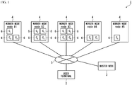
- FIG. 1 is a diagram illustrating the configuration of a system used in the study.
- a system 1 is a system for providing a service to a user terminal 2 such as a PC (Personal Computer), and includes a master node 3 and a plurality of worker nodes 4.
- the master node 3 and each worker node 4 are physical servers for example, and are connected to each other via a network 5 such as a LAN (Local Area Network). Virtual servers may be used as the master node 3 and each worker node 4.
- respective worker nodes 4 are identified by character strings "node #1", "node #2", “node #3", "node #4" and "node #5".
- Each of the worker nodes 4 executes a container engine such as DOCKER (registered trademark) on the host OS, so that each of a plurality of containers 6 starts in each worker node 4.
- DOCKER registered trademark
- the worker node 4 executes an application program having a different function in each of the containers 6, and hence a service combining these application programs is provided to the user terminal 2.
- an architecture that combines application programs having different functions is also called a microservice architecture.
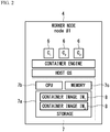
- FIG. 2 is a schematic diagram of the single worker node 4.
- the worker node 4 includes a storage 7a, a CPU (Central Processing Unit) 7b and a memory 7c, as physical resources 7.
- the storage 7a is a storage device such as an HDD (Hard Disk Drive) or an SSD (Solid State Drive), and stores container images 8.
- Each container image 8 is an image file that stores a part of a kernel of the guest OS.
- a name of the container image 8 for starting the container 6 with a name "C i " is represented by "IM i ".
- the container 6 of "C 2 " is started from the container image 8 of "IM 2 ".
- the CPU 7b and the memory 7c cooperate with each other to execute the above-mentioned container engine, so that the container 6 is started from the container image 8 stored in the storage 7a.
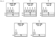
- FIG. 3 is a schematic diagram of the system used in the study at a normal time before failure. In this example, it is assumed that four containers 6 of "C 2 " are started in the worker node 4 of "node #2".
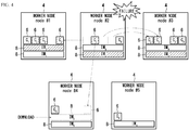
- FIG. 4 is a schematic diagram of the system used in the study at a failure time. As illustrated in FIG. 4 , a case where the worker node 4 of the "node #2" fails is considered. In this case, the four containers 6 of "C 2 " in the failed "node #2" cannot be used. Therefore, in order to continue to provide the service in the system 1, it is necessary to newly start the four containers 6 in the worker node 4 other than "node #2".
- the container 6 of "C 2 " operates in the worker nodes 4 of "node #1” and “node #3" as with the worker node 4 of "node #2" before the failure.
- the container image 8 of "IM 2 " required to start the container 6 of "C 2 " is stored in the storage 7a of each of the worker nodes 4 of "node #1” and "node #3". Therefore, when the container image 8 is used, the container 6 of "C 2 " can start immediately in each of the worker nodes 4 of "node #1" and "node #3".
- each the worker node 4 of "node #1” and “node #3” has only an amount of resources that can start only a part of the four containers 6 of "C 2 " that operate in the worker node 4 of "node #2".
- the worker node 4 of "node #1” has only an amount of surplus resources that can start only a single container 6 of "C 2 "
- the worker node 4 of "node #3” has only an amount of surplus resources that can start only two containers 6 of "C 2 ".
- a download source is a predetermined server connected to the network 5 (see FIG. 1 ), for example. Since this download takes some time, the container 6 of "C 2 " cannot start immediately in the worker node 4 of "node #4", and the availability of the system 1 is reduced.
- a time from downloading the container image 8 to starting the container 6 depends on a capacity of the container image 8 and a line speed of the network 5. As an example, when the container image 8 is already downloaded, a startup time of the container 6 is about several seconds. On the other hand, when the container image 8 is not downloaded yet, it takes more than ten seconds from downloading the container image 8 to starting the container 6. The following measure can be considered to make such download unnecessary.
- FIG. 5 is a schematic diagram illustrating a measure for making the download unnecessary.
- all the container images 8 of "IM 1 " to “IM 5 " are stored in advance in the storages 7a of all the worker nodes 4 of "node #1" to "node #5", as illustrated in FIG. 5 .
- the remaining worker nodes 4 can start the containers 6 of "C 1 " to "C 5 " without downloading the container images 8, thereby increasing the availability of the system 1.
- FIG. 6 is a diagram illustrating the system configuration of a system according to a present embodiment.
- a system 21 is a system for providing services to a user terminal 22 such as the PC, and includes a master node 23 and a plurality of worker nodes 24.
- Each of the master node 23 and the worker nodes 24 is a computer such as a physical server.
- the master node 23 and the worker nodes 24 are connected to each other via a network 25 such as a local area network (LAN).
- LAN local area network
- each of the worker nodes 24 is identified by any one of character strings "node #1", “node #2", ... and "node #n" for uniquely identifying each of the worker nodes 24.
- the system 21 may be constructed by using a cloud service provided by a cloud operator.
- the plurality of physical servers in the data center of the cloud operator are the master node 23 and the worker nodes 24. Further, the master node 23 and the worker nodes 24 may be realized by virtual servers.
- FIG. 7 is a schematic diagram of the worker node 24 according to the present embodiment.
- the worker node 24 includes a storage 27a, a CPU 27b, a memory 27c, and a NIC (Network Interface Card) 27d as physical resources 27.
- the storage 27a is a storage device such as an HDD or SSD, and stores at least one container image 28.
- the container image 28 is an image file that stores a part of the guest OS such as Linux (registered trademark). Also in the present embodiment, a name of the container image 28 for starting a container 26 with a name "C i " is represented by "IM i ", as with the example of FIG. 2 .
- the CPU 27b and the memory 27c cooperate to execute a host OS 29.
- the CPU 27b and the memory 27c cooperate to execute a container engine 30 such as the DOCKER (registered trademark) on the host OS 29, so that the container 26 is started from the container image 28 stored in the storage 27a.
- the CPU 27b and the memory 27c execute inside each container 26 an application program for providing the service to the user terminal 22 by the microservice architecture, for example.
- the NIC 27d is a communication interface for connecting the worker node 24 to the network 25.
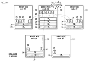
- FIGs. 8 to 10 are schematic diagrams illustrating the outline of the container image arrangement method according to the present embodiment.
- the worker nodes 24 that can anew and immediately start the container 26 of "C 2 " are the worker nodes 24 of "node #1” and “node #3" that store the container image 28 of "IM 2 " corresponding to "C 2 ".
- the master node 23 identifies the worker node 24 of "node #2" as a node having the largest number of containers 26 of "C 2 " in advance.
- the master node 23 determines whether the amounts of resources required to start all the containers 26 of "C 2 " operating in “node #2” can be secured in “node #1” and "node #3". When it is determined that the amounts of resources cannot be secured, the master node 23 instructs the worker node 24 of "node #4" or "node #5" that does not store the container image 28 of "IM 2 " to download the container image 28.
- FIG. 9 is a schematic diagram illustrating a case where the container image 28 of "IM 2 " is downloaded according to the instruction.
- FIG. 9 illustrates a case where the master node 23 instructs the worker node 24 of "node #4" to download the container image 28 of "IM 2 ".
- FIG. 10 is a schematic diagram illustrating a case where the worker node 24 of "node #2" actually fails in this state.
- FIG. 10 illustrates a case where three out of the four containers 26 of "C 2 " that operated in the worker node 24 of "node #2" before the failure are newly started in the worker nodes 24 of "node #1” and “node #3". And, the worker nodes 24 of "node #1” and “node #3” do not have the amount of resources to start the remaining single container 26 of "C 2 ", and the remaining single container 26 is started in the worker node 24 of "node #4".
- the worker node 24 of "node #4" downloads the container image 28 of "IM 2 " in advance before the failure of the worker node 24 of "node #2". Therefore, the worker node 24 of "node #4" does not need to download the container image 28 after the failure, and the container 26 of "C 2 " can start quickly in the worker node 24 of "node #4" without wasting download time.
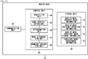
- FIG. 11 is a functional configuration diagram of the worker node 24 according to the present embodiment.
- the worker node 24 includes a communication unit 31, a storage unit 32 and a control unit 33.
- the communication unit 31 is a processing unit realized by the NIC 27d (see FIG. 7 ), and communicates with the master node 23 via the network 25.
- the storage unit 32 is an example of first to fourth storage units, and is realized by the storage 27a (see FIG. 7 ) and the memory 27c.
- the storage unit 32 stores the container image 28.
- FIG. 11 illustrates an example in which the storage unit 32 stores the container images 28 whose names are "IMi" to "IM m ", but the names of the container images 28 may be different for each of the worker nodes 24.
- the storage unit 32 stores resource usage information F 1 , container operation information F 2 and container image storage information F 3 .
- FIGs. 12A to 12C are schematic diagrams illustrating the resource usage information, the container operation information and the container image storage information, respectively.
- the resource usage information F 1 is information indicating the amount of resources currently used by its own node.
- the amount of resources includes a usage rate of the CPU 27b and a usage amount of the memory 27c.
- a total capacity of the memory 27c is also stored in the resource usage information F 1 .
- the container operation information F 2 is information in which the container 26, the number of operations, a CPU usage rate and a memory usage amount are associated with each other.
- the number of operations is the number of containers 26 operating in the its own node.
- the CPU usage rate and the memory usage amount represent a usage rate of the CPU and a usage amount of the memory which are used by the container 26.
- a total value of the CPU usage rates used by all of the plurality of containers 26 in operation is stored in the container operation information F2.
- the total value of the CPU usage rates of the two containers 26 is "30%”. The same also applies to the memory usage amount.
- the container image storage information F 3 is information indicating the container image 28 stored in the storage 27a of its own node.
- Each of the resource usage information F 1 , the container operation information F 2 and the container image storage information F 3 is periodically transmitted by the communication unit 31 to the master node 23 at intervals of about several seconds to several minutes.
- control unit 33 is a processing unit that controls the entire master node 23, and is realized by the CPU 27b and the memory 27c.
- control unit 33 has a container start-up unit 34, a collection unit 35, and a download execution unit 36.
- the container start-up unit 34 is a processing unit that starts the container 26 by using the container image 28.
- the collection unit 35 is a processing unit that periodically collects the resource usage information F 1 , the container operation information F 2 and the container image storage information F 3 , as described above, and stores them in the storage unit 32.
- the collection unit 35 collects the CPU usage rate, the memory usage amount, and the total memory capacity of its own device managed by the host OS 29, and stores them in the resource usage information F 1 .
- the collection unit 35 acquires the number of containers 26 operating in the own device, the CPU usage rate and the memory usage amount of the container 26 from the host OS 29, and stores them in the container operation information F 2 .
- the collection unit 35 acquires the name of the container image stored in the storage 27a of its own device from the host OS 29 and stores it in the container image storage information F 3 .
- the download execution unit 36 is a processing unit that downloads the container image 28 from the network 25 and stores it in the storage unit 32 when receiving an instruction from the master node 23.
- FIG. 13 is a functional configuration diagram of the master node 23 according to the present embodiment. As illustrated in FIG. 13 , the master node 23 includes a communication unit 41, a storage unit 42, and a control unit 43.
- the communication unit 41 is a processing unit that communicates with the master node 23 via the network 25.
- the storage unit 42 is an HDD or a memory, and stores node-by-node resource usage information G 1 , node-by-node container operation information G 2 , node-by-node container image storage information G 3 , and container image arrangement information G 4 .
- FIG. 14 is a schematic diagram of the node-by-node resource usage information G 1 .
- the node-by-node resource usage information G 1 is information indicating the CPU usage rate, the memory usage amount and the total memory capacity for each worker node 24.
- the master node 23 collects the resource usage information F 1 (see FIG. 12A ) from each worker node 24 and merges them to generate the node-by-node resource usage information G 1 .
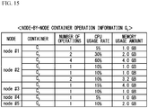
- FIG. 15 is a schematic diagram of the node-by-node container operation information G 2 .
- the node-by-node container operation information G 2 is information in which the container 26, the number of operations, the CPU usage rate and the memory usage amount for each of the worker nodes 24 are associated with each other. These items are the same as the items in the container operation information F 2 (see FIG. 12B ).
- the master node 23 collects the container operation information F 2 from each worker node 24 and merges them to generate the node-by-node container operation information G 2 .
- the total value of the CPU usage rates used by all of the plurality of containers 26 operating in the worker node 24 is stored in the node-by-node container operation information G 2 .
- the total value of the CPU usage rates of the four containers 26 is "60%". The same also applies to the memory usage amount.
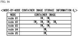
- FIG. 16 is a schematic diagram of the node-by-node container image storage information G 3 .
- the node-by-node container image storage information G 3 is information in which the container image 28 stored in the storage unit 32 of the worker node 24 is associated with the worker node 24.
- the master node 23 collects the container image storage information F 3 from each worker node 24 (see FIG. 12C ) and merges them to generate the node-by-node container image storage information G 3 .
- FIG. 17 is a schematic diagram of the container image arrangement information G 4 .
- the container image arrangement information G 4 is information indicating the worker node 24 where it is recommended to arrange the container image 28 in advance in case of the failure of the worker node 24. For example, it is recommended that the container image 28 of "IM 2 " for starting the container 26 of "C 2 " is stored in the storage 27a of each of the worker nodes 24 of "node #1", “node #2” and "node #3".
- control unit 43 is a processing unit that controls the overall operation of the master node 23, and includes an acquisition unit 44, a node identification unit 45, a determination unit 46, a node determination unit 47 and a download instruction unit 48.
- the acquisition unit 44 is a processing unit that collects the resource usage information F 1 , the container operation information F 2 and the container image storage information F 3 of FIGs. 12A to 12C from each worker node 24 via the communication unit 41.
- the acquisition unit 44 merges the resource usage information F 1 of the respective worker nodes 24 to generate the node-by-node resource usage information G 1 , and stores it in the storage unit 42.
- the acquisition unit 44 merges the container operation information F 2 of the respective worker nodes 24 to generate the node-by-node container operation information G 2 , and stores it in the storage unit 42.
- the acquisition unit 44 merges the container image storage information F 3 of the respective worker nodes 24 to generate the node-by-node container image storage information G 3 , and stores it in the storage unit 42.
- the node identification unit 45 identifies a node having the largest number of containers 26 of "C i " in operation started from the container image 28 of "IM i " among the worker nodes 24, based on the node-by-node container operation information G 2 (see FIG. 15 ).
- the worker node 24 of "node #2" which has the largest number of containers 26 of "C 2 " in operation, i.e., four containers 26 is identified.
- the determination unit 46 is a processing unit that determines whether the container 26 of "C i " operating in the worker node 24 identified by the node identification unit 45 can start in the other worker node 24 that stores the container image 28 of "IM i ".
- the determination unit 46 determines whether the four containers 26 of "C 2 " operating in the worker node 24 of "node #2" can start in the worker node 24 of "node #1" or "node #3". The details of a determination method are described later.
- the node determination unit 47 determines a node to download the container image 28 of "IM i ".
- the node determination unit 47 determines the node to download the container image 28 of "IMi” in this way, the node determination unit 47 adds the determined node as an arrangement destination node corresponding to "IM i " in the container image arrangement information G 4 ( FIG. 17 ).
- the download instruction unit 48 is a processing unit that instructs the worker node 24 determined by the node determination unit 47 to download the container image 28 of "IM i ". As an example, the download instruction unit 48 periodically instructs each of the arrangement destination nodes in the container image arrangement information G 4 ( FIG. 17 ) to download the container image corresponding to each of the arrangement destination nodes.
- a cycle for outputting the instruction is not particularly limited, but is several seconds to several minutes, for example.
- the download instruction unit 48 instructs either worker node 24 of "node #4" or “node #5" to download the container image 28 of "IM 2 ".
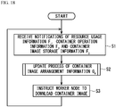
- FIG. 18 is a flowchart of the container image arrangement method according to the present embodiment.
- the communication unit 41 receives notifications of the resource usage information F 1 , the container operation information F 2 and the container image storage information F 3 from each worker node 24 (step S1).
- the node determination unit 47 performs an update process of the container image arrangement information G 4 (step S2). For example, the node determination unit 47 performs the update process of the container image arrangement information G 4 by using each of the resource usage information F 1 , the container operation information F 2 and the container image storage information F 3 . The details of the update process are described later.
- the download instruction unit 48 instructs the worker node 24 corresponding to the arrangement destination node of the container image arrangement information G 4 to download the container image 28 corresponding to the worker node 24 (step S3).
- the container image 28 defined in the container image arrangement information G4 is downloaded to the worker node 24 in advance before any of the worker nodes 24 fails. After that, the above-mentioned steps S1 to S3 are repeated at a cycle of several seconds to several tens of minutes.
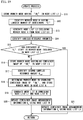
- FIG. 19 is a flowchart of the update process of the container image arrangement information G 4 according to the present embodiment.
- the node identification unit 45 identifies the worker node 24 that stores the container image 28 of "IM i " with reference to the node-by-node container image storage information G3 ( FIG. 16 ), and stores it in a node list L1 (step S11).
- the node identification unit 45 identifies the worker node 24 having the largest number of containers 26 of "C i " started from the container image 28 of "IM i " among the worker nodes 24 in the node list L1 (step S12).
- the worker node 24 identified in S12 is referred to as a worker node H.
- the worker node H is an example of a first node.
- the node identification unit 45 can identify the worker node H by referring to the node-by-node container operation information G2 ( FIG. 15 ).
- the container 26 of "Ci" operating in the worker node H is anew started in the other worker node 24.
- the number of containers 26 of "Ci" anew started in the other worker node when any worker node 24 fails is the largest when the worker node H fails. Therefore, in this embodiment, the case where the worker node H fails is considered as a worst pattern, and in that case, whether the container 26 of "Ci" can start in the other worker node 24 is determined as follows.
- the determination unit 46 generates a node list L2 excluding the worker node H from the node list L1 (step S13).
- each of the worker nodes 24 included in the node list L2 stores the container 26 of "IM i ", it is a candidate node that can start the container 26 of "C i " when the worker node H fails.
- Each of the worker nodes 24 included in the node list L2 is an example of a second node.
- the determination unit 46 identifies various resource amounts as follows (step S14).
- the CPU usage rate is used as the resource amount, but the memory usage amount may be used as the resource amount.
- the determination unit 46 identifies an average resource amount U ave by averaging amounts of resources used by the container 26 of "C i " by the total number of the containers 26 in operation, with reference to the node-by-node container operation information G 2 ( FIG. 15 ).
- the determination unit 46 identifies a sum resource amount U sum by summing the amounts of resources used by the remaining containers 26 excluding the container 26 of "C i " in the worker node H, with reference to the node-by node container operation information G 2 ( FIG. 15 ).
- each of the containers 26 of "C 3 ", “C 4 " and “C 5 " operates as the container 26 other than "C 2 ".
- the determination unit 46 identifies the amount of resources used by the worker node 24 included in the node list L2, with reference to the node-by-node resource usage information G 1 ( FIG. 14 ). Then, the determination unit 46 identifies a first surplus resource amount U res1 available by the worker node 24 included in the node list L2 based on the identified resource amount.
- the "U res1 - U sum " on the right side of the formula (1) indicates a spare capacity capable of starting the container 26 other than "C i " in the worker node 24.
- the divided value h represents the number of containers 26 of "C i " that can start in the worker node 24 of the node list L2 by dividing the spare capacity by U ave .
- the determination unit 46 calculates the number N H of containers 26 of "C i " operating in the worker node H with reference to the node-by-node container operation information G 2 ( FIG. 15 ).
- the determination unit 46 determines that all the containers 26 of "C i " can start in the worker node 24 included in the node list L2.
- the determination unit 46 determines that all the containers 26 of "C i " cannot start in the worker node 24 included in the node list L2.
- the determination unit 46 determines that all four containers 26 of "C 2 " operating in the worker node of "node #2" cannot start in each of the worker nodes 24 of "node #1" and "node #3" included in the node list L2.
- step S15 NO
- the process proceeds to step S16.
- the node determination unit 47 identifies the worker node 24 that does not store the container image 28 of "IMi" with reference to the node-by-node container image storage information G 3 (see FIG. 16 ), and stores it in a node list L3.
- Each worker node 24 included in the node list L3 is an example of a fourth node, and is a candidate for the worker node 24 that stores the container image 28 of "IM i " in advance when the worker node H fails.
- the node determination unit 47 identifies a second surplus resource amount U res2 available by each of the worker nodes 24 included in the node list L3 with reference to the node-by-node resource usage information G 1 ( FIG. 14 ) (step S17).
- the node determination unit 47 determines a node to download the container image 28 of "IM i " from the worker nodes 24 included in the node list L3 (step S18).
- the node determination unit 47 determines whether the following formula (2) is satisfied for each of the worker nodes 24 included in the node list L3.
- the average resource amount U ave on the left side of the formula (2) indicates the average resource amount obtained by averaging the amounts of resources used by the container 26 of "C i " as described above. Therefore, "U res2 / U ave “ on the left side of the formula (2) indicates the number of containers 26 of "C i " that can start in the single worker node 24 included in the node list L3.
- N H - h on the right side of the formula (2) indicates the number of containers 26 that cannot start in the worker node 24 in the node list L2 among the containers 26 of "C i " operating in the worker node H.
- the container 26 of "Ci" that cannot start in the worker node 24 in the node list L2 can start in the single worker node 24 included in the node list L3.
- the node determination unit 47 determines the worker node 24 which satisfies the formula (2) as the node to download the container image 28 of "IMi", and stores it in a node list K.
- Each worker node 24 included in the node list K is an example of a third node.
- both of "node #4" and "node #5" satisfy the formula (2).
- the node determination unit 47 generates a node list M combining the node list L1 and the node list K (step S19).
- the node list M is a list of the worker node 24 that store the container image 28 of the "IM i " in the storage unit 32 (see FIG. 11 ).
- the node determination unit 47 updates the container image arrangement information G 4 ( FIG. 17 ) using the node list M (step S20). As an example, the node determination unit 47 updates the arrangement destination node corresponding to the container image 28 of "IM i " in the container image arrangement information G 4 to the content of the node list M.
- step S15 when it is determined that all the containers 26 of "C i " operating in the worker node H can start in the worker node 24 included in the node list L2, the process proceeds to step S21.
- step S21 the node determination unit 47 replaces the arrangement destination node corresponding to the container image 28 of "IM i " in the container image arrangement information G 4 ( FIG. 17 ) with the content of the node list L1.
- the node list L1 is a list of the worker node 24 that store the container image 28 of "IM i ". Therefore, the arrangement destination node corresponding to the container image 28 of "IM i " in the container image arrangement information G 4 ( FIG. 17 ) matches the content of the node list L1. However, if the content of the container image arrangement information G 4 is missing for some reason, the missing content can be added by executing step S21.
- step S2 the download instruction unit 48 causes each worker node 24 identified by the container image arrangement information G 4 to download the container image 28 in advance. For this reason, even if any worker node 24 fails, the other worker node 24 does not need to download the container image 28 for starting the container 26 operating in the failed worker node 24. As a result, even if any worker node 24 fails, the container 26 can start immediately, and the availability of the system 21 can be improved.
- the node identification unit 45 identifies the worker node H. Since the worker node H is the node having the largest number of containers 26 of "C i " in operation among the plurality of worker nodes 24, the worker node H is the worker node 24 having the largest number of containers 26 of "C i " to be migrated to the other worker node in the case of the failure. Since the worker node 24 that stores the container image "IM i " is determined based on the worker node H, even if any worker node 24 having the container 26 of "C i " in operation fails, the container 26 is immediately started in the other worker node 24.
- step S1 the communication unit 41 receives the notifications of the resource usage information F 1 , the container operation information F 2 and the container image storage information F 3 from each worker node 24. Therefore, the determination unit 46 can calculate each of the average resource amount U ave , the sum resource amount U sum and the first surplus resource amount U res1 based on the notified information in step S14. Then, the determination unit 46 can determine in step S15 whether all the containers 26 of "C i " operating in the worker node H can start in the worker node 24 included in the node list L2, based on these resource amounts.
- the node determination unit 47 can calculate the second surplus resource amount U res2 based on the resource usage information F 1 in step S17.
- the node determination unit 47 can determine which of the worker nodes 24 included in the node list L3 downloads the container image 28 based on the second surplus resource amount Ures2 in step S18.
- FIG. 21 is a diagram illustrating the hardware configuration of the master node 23 according to the present embodiment.
- the master node 23 includes a storage 23a, a memory 23b, a CPU 23c, a NIC 23d, a display device 23e and an input device 23f. These elements are connected to each other by a bus 23g.
- the storage 23a is a non-volatile storage device such as an HDD or an SSD, and stores a container image arrangement program 40 according to the present embodiment.
- the container image arrangement program 40 may be recorded on a computer-readable recording medium 23h, and the CPU 23c may read the container image arrangement program 40 from the recording medium 23 h.
- Examples of such a recording medium 23h include physically portable recording media such as a CD-ROM (Compact Disc-Read Only Memory), a DVD (Digital Versatile Disc), and a USB (Universal Serial Bus) memory. Further, a semiconductor memory such as a flash memory, or a hard disk drive may be used as the recording medium 23h.
- the recording medium 23h is not a temporary medium such as a carrier wave having no physical form.
- the container image arrangement program 40 may be stored in a device connected to a public line, the Internet, a LAN (Local Area Network), or the like.
- the CPU 23c may read and execute the container image arrangement program 40.
- the memory 23b is hardware that temporarily stores data, such as a DRAM, and the container image arrangement program 40 is deployed on the memory 23b.
- the CPU 23c is a processor that controls each element in the master node 23. Further, the CPU 23c executes the container image arrangement program 40 in cooperation with the memory 23b, which realizes the control unit 43 of FIG. 13 .
- control unit 43 includes the acquisition unit 44, the node identification unit 45, the determination unit 46, the node determination unit 47, and the download instruction unit 48. Further, the storage unit 42 of FIG. 13 is realized by the storage 23 a and the memory 23b.
- the NIC 30d is a communication interface for connecting the master node 23 to the network 25, and is hardware that realizes the communication unit 41 of FIG. 13 .
- the display device 23e is hardware such as a liquid crystal display device, and displays various information to an administrator of the system 21.
- the input device 23f is hardware such as a keyboard and a mouse. For example, the administrator issues various instructions to the master node 23 by operating the input device 23f.
Landscapes
- Engineering & Computer Science (AREA)
- Theoretical Computer Science (AREA)
- General Engineering & Computer Science (AREA)
- Physics & Mathematics (AREA)
- General Physics & Mathematics (AREA)
- Software Systems (AREA)
- Quality & Reliability (AREA)
- Computing Systems (AREA)
- Computer Hardware Design (AREA)
- Mathematical Physics (AREA)
- Information Retrieval, Db Structures And Fs Structures Therefor (AREA)
- Medical Treatment And Welfare Office Work (AREA)
Abstract
Description
- The present invention relates to a container image arrangement method and a container image arrangement program.
- VM (Virtual Machine) virtualization technology and container virtualization technology are known as technologies for virtualizing computers. Among these, the VM virtualization technology is a technology that performs virtualization by executing a guest OS (Operating System) on a host OS, and has large overhead for executing the guest OS.
- On the other hand, the container virtualization technology is a technology that virtualizes using only a part of a kernel of the guest OS. Since only the part of the kernel is used in this way, the container virtualization technology has an advantage that the overhead for virtualization is small and light compared with the VM virtualization technology. In the container virtualization technology, a plurality of user spaces are generated independent of each other. These user spaces are called containers, and an application program is executed in each of the containers. For example, there is DOCKER (registered trademark) as a container engine which is a program for generating the containers.
- Since the container has small overhead for virtualization as described above, the container can be easily migrated between nodes. Therefore, it is possible to easily construct a system having excellent scalability by generating the container for each of the plurality of nodes.
- However, in the system using the container in this way, there is room for improvement in that a container that was started in the failed node can be start quickly in the other node. Note that the technique related to the present disclosure is disclosed in Japanese Laid-open Patent Publication No.
2019-66985 - It is an object of the present disclosure to be able to quickly start a container in another node when any node fails.
- According to an aspect of the present disclosure, there is provided a container image arrangement method executed by a processor included in a computer to execute a process, the computer being connected to each of a plurality of nodes, the process including: identifying a first node that has a first storage storing a container image and has a largest number of containers started from the container image among the plurality of nodes; determining whether the container operating in the first node is capable of starting in a second node among the plurality of nodes other than the first node, where the second has a second storage storing the container image; and storing the container image in a third storage included in a third node different from each of the first node and the second node among the plurality of the nodes when it is determined that the container is not capable of starting in the second node.
- According to the present disclosure, it is possible to quickly start a container in another node when any node fails.
-
-
FIG. 1 is a diagram illustrating the configuration of a system used in the study; -
FIG. 2 is a schematic diagram of a single worker node in the system used in the study; -
FIG. 3 is a schematic diagram of the system used in the study at a normal time before failure; -
FIG. 4 is a schematic diagram of the system used in the study at a failure time; -
FIG. 5 is a schematic diagram illustrating a measure for making download unnecessary; -
FIG. 6 is a diagram illustrating the system configuration of a system according to a present embodiment; -
FIG. 7 is a schematic diagram of a worker node according to the present embodiment; -
FIG. 8 is a schematic diagram illustrating an outline of a container image arrangement method according to the present embodiment (part 1); -
FIG. 9 is a schematic diagram illustrating the outline of the container image arrangement method according to the present embodiment (part 2); -
FIG. 10 is a schematic diagram illustrating the outline of the container image arrangement method according to the present embodiment (part 3); -
FIG. 11 is a functional configuration diagram of the worker node according to the present embodiment; -
FIG. 12A is a schematic diagram of resource usage information according to the present embodiment; -
FIG. 12B is a schematic diagram of container operation information according to the present embodiment; -
FIG. 12C is a schematic diagram of container image storage information according to the present embodiment; -
FIG. 13 is a functional configuration diagram of a master node according to the present embodiment; -
FIG. 14 is a schematic diagram of node-by-node resource usage information according to the present embodiment; -
FIG. 15 is a schematic diagram of node-by-node container operation information according to the present embodiment; -
FIG. 16 is a schematic diagram of node-by-node container image storage information according to the present embodiment; -
FIG. 17 is a schematic diagram of container image arrangement information according to the present embodiment; -
FIG. 18 is a flowchart of a container image arrangement method according to the present embodiment; -
FIG. 19 is a flowchart of an update process of the container image arrangement information according to the present embodiment; -
FIG. 20 is a schematic diagram illustrating an example of container image arrangement information G4 updated by a node determination unit in the case of i = 2; and -
FIG. 21 is a diagram illustrating the hardware configuration of the master node according to the present embodiment. - Prior to the description of the present embodiment, matters studied by an inventor will be described.
-
FIG. 1 is a diagram illustrating the configuration of a system used in the study. Asystem 1 is a system for providing a service to auser terminal 2 such as a PC (Personal Computer), and includes amaster node 3 and a plurality ofworker nodes 4. Themaster node 3 and eachworker node 4 are physical servers for example, and are connected to each other via anetwork 5 such as a LAN (Local Area Network). Virtual servers may be used as themaster node 3 and eachworker node 4. Hereinafter,respective worker nodes 4 are identified by character strings "node # 1", "node # 2", "node # 3", "node # 4" and "node # 5". - Each of the
worker nodes 4 executes a container engine such as DOCKER (registered trademark) on the host OS, so that each of a plurality ofcontainers 6 starts in eachworker node 4. Here, each of the plurality ofcontainers 6 is uniquely identified by a name "Ci" (i = 1, 2, ... 5). Twocontainers 6 with different names have different images of guest OSs to be used. - The
worker node 4 executes an application program having a different function in each of thecontainers 6, and hence a service combining these application programs is provided to theuser terminal 2. In this way, an architecture that combines application programs having different functions is also called a microservice architecture. -
FIG. 2 is a schematic diagram of thesingle worker node 4. As illustrated inFIG. 2 , theworker node 4 includes astorage 7a, a CPU (Central Processing Unit) 7b and amemory 7c, asphysical resources 7. Thestorage 7a is a storage device such as an HDD (Hard Disk Drive) or an SSD (Solid State Drive), and storescontainer images 8. Eachcontainer image 8 is an image file that stores a part of a kernel of the guest OS. Here, a name of thecontainer image 8 for starting thecontainer 6 with a name "Ci" is represented by "IMi". For example, thecontainer 6 of "C2" is started from thecontainer image 8 of "IM2". - The
CPU 7b and thememory 7c cooperate with each other to execute the above-mentioned container engine, so that thecontainer 6 is started from thecontainer image 8 stored in thestorage 7a. - By the way, in the
system 1 illustrated inFIG. 1 , it is necessary to start thecontainer 6 that was started in the failedworker node 4 inother worker node 4, in order to continue to provide the service even if a part of theworker nodes 4 fails. -
FIG. 3 is a schematic diagram of the system used in the study at a normal time before failure. In this example, it is assumed that fourcontainers 6 of "C2" are started in theworker node 4 of "node # 2". -
FIG. 4 is a schematic diagram of the system used in the study at a failure time. As illustrated inFIG. 4 , a case where theworker node 4 of the "node # 2" fails is considered. In this case, the fourcontainers 6 of "C2" in the failed "node # 2" cannot be used. Therefore, in order to continue to provide the service in thesystem 1, it is necessary to newly start the fourcontainers 6 in theworker node 4 other than "node # 2". - Here, it is assumed that the
container 6 of "C2" operates in theworker nodes 4 of "node # 1" and "node # 3" as with theworker node 4 of "node # 2" before the failure. In this case, thecontainer image 8 of "IM2" required to start thecontainer 6 of "C2" is stored in thestorage 7a of each of theworker nodes 4 of "node # 1" and "node # 3". Therefore, when thecontainer image 8 is used, thecontainer 6 of "C2" can start immediately in each of theworker nodes 4 of "node # 1" and "node # 3". - However, when the
containers 6 other than "C2" operates in theworker nodes 4 of "node # 1" and "node # 3", an amount of surplus resources such as theCPU 7b and thememory 7c in theworker nodes 4 may be insufficient. - In this case, each the
worker node 4 of "node # 1" and "node # 3" has only an amount of resources that can start only a part of the fourcontainers 6 of "C2" that operate in theworker node 4 of "node # 2". For example, it is assumed that theworker node 4 of "node # 1" has only an amount of surplus resources that can start only asingle container 6 of "C2", and theworker node 4 of "node # 3" has only an amount of surplus resources that can start only twocontainers 6 of "C2". In this case, it is necessary to start a single remainingcontainer 6 of "C2" included in the worker node of "node # 2", in theother worker node 4 that does not have thecontainer image 8 of "IM2". - For example, a case where the
container 6 of "C2" is started by theworker node 4 of "node # 4" is considered. Since thestorage 7a in theworker node 4 of "node # 4" does not have thecontainer image 8 of "IM2", it is necessary to download thecontainer image 8 to theworker node 4 of "node # 4". A download source is a predetermined server connected to the network 5 (seeFIG. 1 ), for example. Since this download takes some time, thecontainer 6 of "C2" cannot start immediately in theworker node 4 of "node # 4", and the availability of thesystem 1 is reduced. - A time from downloading the
container image 8 to starting thecontainer 6 depends on a capacity of thecontainer image 8 and a line speed of thenetwork 5. As an example, when thecontainer image 8 is already downloaded, a startup time of thecontainer 6 is about several seconds. On the other hand, when thecontainer image 8 is not downloaded yet, it takes more than ten seconds from downloading thecontainer image 8 to starting thecontainer 6. The following measure can be considered to make such download unnecessary. -
FIG. 5 is a schematic diagram illustrating a measure for making the download unnecessary. In this example, all thecontainer images 8 of "IM1" to "IM5" are stored in advance in thestorages 7a of all theworker nodes 4 of "node # 1" to "node # 5", as illustrated inFIG. 5 . Thereby, even if any of theworker nodes 4 fails, the remainingworker nodes 4 can start thecontainers 6 of "C1" to "C5" without downloading thecontainer images 8, thereby increasing the availability of thesystem 1. - However, in this case, since the
container images 8 that are not normally used are stored in thestorage 7a, the capacity of thestorage 7a is wasted. -
FIG. 6 is a diagram illustrating the system configuration of a system according to a present embodiment. Asystem 21 is a system for providing services to auser terminal 22 such as the PC, and includes amaster node 23 and a plurality ofworker nodes 24. Each of themaster node 23 and theworker nodes 24 is a computer such as a physical server. Themaster node 23 and theworker nodes 24 are connected to each other via anetwork 25 such as a local area network (LAN). Here, each of theworker nodes 24 is identified by any one of character strings "node # 1", "node # 2", ... and "node #n" for uniquely identifying each of theworker nodes 24. - The
system 21 may be constructed by using a cloud service provided by a cloud operator. In this case, the plurality of physical servers in the data center of the cloud operator are themaster node 23 and theworker nodes 24. Further, themaster node 23 and theworker nodes 24 may be realized by virtual servers. -
FIG. 7 is a schematic diagram of theworker node 24 according to the present embodiment. Theworker node 24 includes astorage 27a, aCPU 27b, amemory 27c, and a NIC (Network Interface Card) 27d asphysical resources 27. Thestorage 27a is a storage device such as an HDD or SSD, and stores at least onecontainer image 28. Thecontainer image 28 is an image file that stores a part of the guest OS such as Linux (registered trademark). Also in the present embodiment, a name of thecontainer image 28 for starting acontainer 26 with a name "Ci" is represented by "IMi", as with the example ofFIG. 2 . - Then, the
CPU 27b and thememory 27c cooperate to execute ahost OS 29. TheCPU 27b and thememory 27c cooperate to execute acontainer engine 30 such as the DOCKER (registered trademark) on thehost OS 29, so that thecontainer 26 is started from thecontainer image 28 stored in thestorage 27a. Further, theCPU 27b and thememory 27c execute inside eachcontainer 26 an application program for providing the service to theuser terminal 22 by the microservice architecture, for example. - The
NIC 27d is a communication interface for connecting theworker node 24 to thenetwork 25. - Next, a description is given of an outline of a container image arrangement method according to the present embodiment.
FIGs. 8 to 10 are schematic diagrams illustrating the outline of the container image arrangement method according to the present embodiment. - In this example, it is assumed that the
container image 28 of "IM2" is stored in thestorage 27a of each of theworker nodes 24 of "node # 1", "node # 2" and "node # 3", as illustrated inFIG. 8 . Further, a case where thecontainer 26 of "C2" started from thecontainer image 28 of "IM2" operates in theworker nodes 24 of "node # 1", "node # 2" and "node # 3" is considered. - When the
worker node 24 of "node # 2" fails in this state, all thecontainers 26 of "C2" in theworker node 24 of "node # 2" need to be started anew byother worker nodes 24 in order for thesystem 21 to continue to provide the service. - The
worker nodes 24 that can anew and immediately start thecontainer 26 of "C2" are theworker nodes 24 of "node # 1" and "node # 3" that store thecontainer image 28 of "IM2" corresponding to "C2". - However, in the
worker node 24 of "node # 2", the number ofcontainers 26 of "C2" in operation is 4, and the number ofcontainers 26 of "C2" in operation is the largest among all theworker nodes 24. Therefore, there is a possibility that amounts of resources required to start all thecontainers 26 of "C2" operating in "node # 2" cannot be secured in "node # 1" and "node # 3". - Therefore, in the present embodiment, before the
worker node 24 fails, themaster node 23 identifies theworker node 24 of "node # 2" as a node having the largest number ofcontainers 26 of "C2" in advance. - Further, the
master node 23 determines whether the amounts of resources required to start all thecontainers 26 of "C2" operating in "node # 2" can be secured in "node # 1" and "node # 3". When it is determined that the amounts of resources cannot be secured, themaster node 23 instructs theworker node 24 of "node # 4" or "node # 5" that does not store thecontainer image 28 of "IM2" to download thecontainer image 28. -
FIG. 9 is a schematic diagram illustrating a case where thecontainer image 28 of "IM2" is downloaded according to the instruction. -
FIG. 9 illustrates a case where themaster node 23 instructs theworker node 24 of "node # 4" to download thecontainer image 28 of "IM2". -
FIG. 10 is a schematic diagram illustrating a case where theworker node 24 of "node # 2" actually fails in this state. -
FIG. 10 illustrates a case where three out of the fourcontainers 26 of "C2" that operated in theworker node 24 of "node # 2" before the failure are newly started in theworker nodes 24 of "node # 1" and "node # 3". And, theworker nodes 24 of "node # 1" and "node # 3" do not have the amount of resources to start the remainingsingle container 26 of "C2", and the remainingsingle container 26 is started in theworker node 24 of "node # 4". - In the present embodiment, the
worker node 24 of "node # 4" downloads thecontainer image 28 of "IM2" in advance before the failure of theworker node 24 of "node # 2". Therefore, theworker node 24 of "node # 4" does not need to download thecontainer image 28 after the failure, and thecontainer 26 of "C2" can start quickly in theworker node 24 of "node # 4" without wasting download time. - Next, the container image arrangement method according to the present embodiment is described with reference to the functional configuration of each of the
worker nodes 24 and themaster node 23. -
FIG. 11 is a functional configuration diagram of theworker node 24 according to the present embodiment. As illustrated inFIG. 11 , theworker node 24 includes acommunication unit 31, astorage unit 32 and acontrol unit 33. Thecommunication unit 31 is a processing unit realized by theNIC 27d (seeFIG. 7 ), and communicates with themaster node 23 via thenetwork 25. - The
storage unit 32 is an example of first to fourth storage units, and is realized by thestorage 27a (seeFIG. 7 ) and thememory 27c. Thestorage unit 32 stores thecontainer image 28.FIG. 11 illustrates an example in which thestorage unit 32 stores thecontainer images 28 whose names are "IMi" to "IMm", but the names of thecontainer images 28 may be different for each of theworker nodes 24. - Further, the
storage unit 32 stores resource usage information F1, container operation information F2 and container image storage information F3. -
FIGs. 12A to 12C are schematic diagrams illustrating the resource usage information, the container operation information and the container image storage information, respectively. As illustrated inFIG. 12A , the resource usage information F1 is information indicating the amount of resources currently used by its own node. The amount of resources includes a usage rate of theCPU 27b and a usage amount of thememory 27c. A total capacity of thememory 27c is also stored in the resource usage information F1. - As illustrated in
FIG. 12B , the container operation information F2 is information in which thecontainer 26, the number of operations, a CPU usage rate and a memory usage amount are associated with each other. The number of operations is the number ofcontainers 26 operating in the its own node. The CPU usage rate and the memory usage amount represent a usage rate of the CPU and a usage amount of the memory which are used by thecontainer 26. - When the number of operations is plural, a total value of the CPU usage rates used by all of the plurality of
containers 26 in operation is stored in the container operation information F2. For example, in thecontainer 26 of "C2" in which number of operations is "2", the total value of the CPU usage rates of the twocontainers 26 is "30%". The same also applies to the memory usage amount. - As illustrated in
FIG. 12C , the container image storage information F3 is information indicating thecontainer image 28 stored in thestorage 27a of its own node. - Each of the resource usage information F1, the container operation information F2 and the container image storage information F3 is periodically transmitted by the
communication unit 31 to themaster node 23 at intervals of about several seconds to several minutes. - Referring again to
FIG. 11 , thecontrol unit 33 is a processing unit that controls theentire master node 23, and is realized by theCPU 27b and thememory 27c. In this example, thecontrol unit 33 has a container start-upunit 34, acollection unit 35, and adownload execution unit 36. - The container start-up
unit 34 is a processing unit that starts thecontainer 26 by using thecontainer image 28. - The
collection unit 35 is a processing unit that periodically collects the resource usage information F1, the container operation information F2 and the container image storage information F3, as described above, and stores them in thestorage unit 32. - For example, the
collection unit 35 collects the CPU usage rate, the memory usage amount, and the total memory capacity of its own device managed by thehost OS 29, and stores them in the resource usage information F1. Thecollection unit 35 acquires the number ofcontainers 26 operating in the own device, the CPU usage rate and the memory usage amount of thecontainer 26 from thehost OS 29, and stores them in the container operation information F2. Further, thecollection unit 35 acquires the name of the container image stored in thestorage 27a of its own device from thehost OS 29 and stores it in the container image storage information F3. - The
download execution unit 36 is a processing unit that downloads thecontainer image 28 from thenetwork 25 and stores it in thestorage unit 32 when receiving an instruction from themaster node 23. -
FIG. 13 is a functional configuration diagram of themaster node 23 according to the present embodiment. As illustrated inFIG. 13 , themaster node 23 includes acommunication unit 41, astorage unit 42, and acontrol unit 43. - The
communication unit 41 is a processing unit that communicates with themaster node 23 via thenetwork 25. - The
storage unit 42 is an HDD or a memory, and stores node-by-node resource usage information G1, node-by-node container operation information G2, node-by-node container image storage information G3, and container image arrangement information G4. -
FIG. 14 is a schematic diagram of the node-by-node resource usage information G1. As illustrated inFIG. 14 , the node-by-node resource usage information G1 is information indicating the CPU usage rate, the memory usage amount and the total memory capacity for eachworker node 24. Themaster node 23 collects the resource usage information F1 (seeFIG. 12A ) from eachworker node 24 and merges them to generate the node-by-node resource usage information G1. -
FIG. 15 is a schematic diagram of the node-by-node container operation information G2. The node-by-node container operation information G2 is information in which thecontainer 26, the number of operations, the CPU usage rate and the memory usage amount for each of theworker nodes 24 are associated with each other. These items are the same as the items in the container operation information F2 (seeFIG. 12B ). Themaster node 23 collects the container operation information F2 from eachworker node 24 and merges them to generate the node-by-node container operation information G2. - When the number of operations in any
worker node 24 is plural, the total value of the CPU usage rates used by all of the plurality ofcontainers 26 operating in theworker node 24 is stored in the node-by-node container operation information G2. For example, in thecontainers 26 of "C2" in which the number of operations is "4" in the worker node of "node # 2", the total value of the CPU usage rates of the fourcontainers 26 is "60%". The same also applies to the memory usage amount. -
FIG. 16 is a schematic diagram of the node-by-node container image storage information G3. The node-by-node container image storage information G3 is information in which thecontainer image 28 stored in thestorage unit 32 of theworker node 24 is associated with theworker node 24. Themaster node 23 collects the container image storage information F3 from each worker node 24 (seeFIG. 12C ) and merges them to generate the node-by-node container image storage information G3. -
FIG. 17 is a schematic diagram of the container image arrangement information G4. The container image arrangement information G4 is information indicating theworker node 24 where it is recommended to arrange thecontainer image 28 in advance in case of the failure of theworker node 24. For example, it is recommended that thecontainer image 28 of "IM2" for starting thecontainer 26 of "C2" is stored in thestorage 27a of each of theworker nodes 24 of "node # 1", "node # 2" and "node # 3". - Referring again to
FIG. 13 , thecontrol unit 43 is a processing unit that controls the overall operation of themaster node 23, and includes anacquisition unit 44, anode identification unit 45, adetermination unit 46, anode determination unit 47 and adownload instruction unit 48. - The
acquisition unit 44 is a processing unit that collects the resource usage information F1, the container operation information F2 and the container image storage information F3 ofFIGs. 12A to 12C from eachworker node 24 via thecommunication unit 41. Theacquisition unit 44 merges the resource usage information F1 of therespective worker nodes 24 to generate the node-by-node resource usage information G1, and stores it in thestorage unit 42. Similarly, theacquisition unit 44 merges the container operation information F2 of therespective worker nodes 24 to generate the node-by-node container operation information G2, and stores it in thestorage unit 42. Further, theacquisition unit 44 merges the container image storage information F3 of therespective worker nodes 24 to generate the node-by-node container image storage information G3, and stores it in thestorage unit 42. - The
node identification unit 45 identifies a node in which thecontainer image 28 of "IMi" is stored in thestorage 27a among the plurality ofworker nodes 24, based on the node-by-node container image storage information G3 (seeFIG. 16 ). For example, in the case of i = 2, each of theworker nodes 24 of "node # 1", "node # 2" and "node # 3" is identified. - Further, the
node identification unit 45 identifies a node having the largest number ofcontainers 26 of "Ci" in operation started from thecontainer image 28 of "IMi" among theworker nodes 24, based on the node-by-node container operation information G2 (seeFIG. 15 ). In the example ofFIG. 15 , in the case of i = 2, theworker node 24 of "node # 2" which has the largest number ofcontainers 26 of "C2" in operation, i.e., fourcontainers 26 is identified. - The
determination unit 46 is a processing unit that determines whether thecontainer 26 of "Ci" operating in theworker node 24 identified by thenode identification unit 45 can start in theother worker node 24 that stores thecontainer image 28 of "IMi". - In the above-mentioned example of i = 2, the
determination unit 46 determines whether the fourcontainers 26 of "C2" operating in theworker node 24 of "node # 2" can start in theworker node 24 of "node # 1" or "node # 3". The details of a determination method are described later. - When the
determination unit 46 determines that thecontainer 26 of "Ci" cannot start in theworker node 24 storing thecontainer image 28 of "IMi", thenode determination unit 47 determines a node to download thecontainer image 28 of "IMi". - For example, in the case of i = 2 described above, either
worker node 24 of "node # 4" or "node # 5" is determined as the node to download thecontainer image 28 of "IM2". The details of a determination method are described later. - When the
node determination unit 47 determines the node to download thecontainer image 28 of "IMi" in this way, thenode determination unit 47 adds the determined node as an arrangement destination node corresponding to "IMi" in the container image arrangement information G4 (FIG. 17 ). - The
download instruction unit 48 is a processing unit that instructs theworker node 24 determined by thenode determination unit 47 to download thecontainer image 28 of "IMi". As an example, thedownload instruction unit 48 periodically instructs each of the arrangement destination nodes in the container image arrangement information G4 (FIG. 17 ) to download the container image corresponding to each of the arrangement destination nodes. A cycle for outputting the instruction is not particularly limited, but is several seconds to several minutes, for example. - When i = 2 is set in
FIG. 8 , thedownload instruction unit 48 instructs eitherworker node 24 of "node # 4" or "node # 5" to download thecontainer image 28 of "IM2". - Next, a description is given of a container image arrangement method according to the present embodiment.
FIG. 18 is a flowchart of the container image arrangement method according to the present embodiment. - First, the
communication unit 41 receives notifications of the resource usage information F1, the container operation information F2 and the container image storage information F3 from each worker node 24 (step S1). - Next, the
node determination unit 47 performs an update process of the container image arrangement information G4 (step S2). For example, thenode determination unit 47 performs the update process of the container image arrangement information G4 by using each of the resource usage information F1, the container operation information F2 and the container image storage information F3. The details of the update process are described later. - Next, the
download instruction unit 48 instructs theworker node 24 corresponding to the arrangement destination node of the container image arrangement information G4 to download thecontainer image 28 corresponding to the worker node 24 (step S3). - Thereby, the
container image 28 defined in the container image arrangement information G4 is downloaded to theworker node 24 in advance before any of theworker nodes 24 fails. After that, the above-mentioned steps S1 to S3 are repeated at a cycle of several seconds to several tens of minutes. - Next, a description is given of the update process of the container image arrangement information G4 in step S2.
-
FIG. 19 is a flowchart of the update process of the container image arrangement information G4 according to the present embodiment. - This flowchart can be executed regardless of a value of a subscript i in "Ci" and "IMi", but the case of i = 2 is described below as an example.
- First, the
node identification unit 45 identifies theworker node 24 that stores thecontainer image 28 of "IMi" with reference to the node-by-node container image storage information G3 (FIG. 16 ), and stores it in a node list L1 (step S11). - When i = 2 is set in
FIG. 8 , the node list L1 is represented by L1 = {node # 1,node # 2, node #3 }. - Next, the
node identification unit 45 identifies theworker node 24 having the largest number ofcontainers 26 of "Ci" started from thecontainer image 28 of "IMi" among theworker nodes 24 in the node list L1 (step S12). Hereinafter, theworker node 24 identified in S12 is referred to as a worker node H. The worker node H is an example of a first node. Thenode identification unit 45 can identify the worker node H by referring to the node-by-node container operation information G2 (FIG. 15 ). - When i = 2 is set in
FIG. 15 , theworker node 24 having the largest number ofcontainers 26 of "C2" in operation is "node # 2", and hence the worker node H is theworker node 24 of "node # 2" (H = node #2). - When the worker node H fails, the
container 26 of "Ci" operating in the worker node H is anew started in theother worker node 24. Thus, the number ofcontainers 26 of "Ci" anew started in the other worker node when anyworker node 24 fails is the largest when the worker node H fails. Therefore, in this embodiment, the case where the worker node H fails is considered as a worst pattern, and in that case, whether thecontainer 26 of "Ci" can start in theother worker node 24 is determined as follows. - Next, the
determination unit 46 generates a node list L2 excluding the worker node H from the node list L1 (step S13). In the example ofFIG. 8 , the node list L2 is represented by L2 = {node # 1, node #3}. - Since each of the
worker nodes 24 included in the node list L2 stores thecontainer 26 of "IMi", it is a candidate node that can start thecontainer 26 of "Ci" when the worker node H fails. Each of theworker nodes 24 included in the node list L2 is an example of a second node. - Next, the
determination unit 46 identifies various resource amounts as follows (step S14). In the present embodiment, the CPU usage rate is used as the resource amount, but the memory usage amount may be used as the resource amount. - First, the
determination unit 46 identifies an average resource amount Uave by averaging amounts of resources used by thecontainer 26 of "Ci" by the total number of thecontainers 26 in operation, with reference to the node-by-node container operation information G2 (FIG. 15 ). - The average resource amount Uave is an average value of the amounts of resources used by the
container 26 of "Ci". For example, when the average resource amount Uave is calculated for thecontainer 26 of "C2" inFIG. 15 , the average resource amount Uave is 15% (i.e., Uave = (30% + 60% + 15%) / (2 + 4 + 1) = 15%). - Further, the
determination unit 46 identifies a sum resource amount Usum by summing the amounts of resources used by the remainingcontainers 26 excluding thecontainer 26 of "Ci" in the worker node H, with reference to the node-by node container operation information G2 (FIG. 15 ). - When i = 2 is set in
FIG. 15 , the worker node H is theworker node 24 of "node # 2" as described above (H = node #2). In theworker node 24 of "node # 2", each of thecontainers 26 of "C3", "C4" and "C5" operates as thecontainer 26 other than "C2". In this case, the sum resource amount Usum is 30% (Usum = 10% + 10% + 10% = 30%). - The
determination unit 46 identifies the amount of resources used by theworker node 24 included in the node list L2, with reference to the node-by-node resource usage information G1 (FIG. 14 ). Then, thedetermination unit 46 identifies a first surplus resource amount Ures1 available by theworker node 24 included in the node list L2 based on the identified resource amount. - The case of L2 = {
node # 1, node #3} is considered as described above. In this case, in the example ofFIG. 14 , a surplus resource of theworker node 24 of "node # 1" is 50% (i.e., 100% -50% = 50%), and a surplus resource of theworker node 24 of "node # 3" is 20% (i.e., 100% -80% = 20%). Therefore, the first surplus resource amount Ures1 is 70% (i.e., Ures1 = 50% + 20% = 70%). - Next, the
determination unit 46 determines whether all thecontainers 26 of "Ci" operating in the worker node H can start in theworker node 24 included in the node list L2 (step SI5). In order to make this determination, thedetermination unit 46 calculates a divided value h of the following formula (1).
- When the
container 26 other than "Ci" in the worker node H is started in theworker node 24 of the node list L2, the "Ures1 - Usum" on the right side of the formula (1) indicates a spare capacity capable of starting thecontainer 26 other than "Ci" in theworker node 24. Then, the divided value h represents the number ofcontainers 26 of "Ci" that can start in theworker node 24 of the node list L2 by dividing the spare capacity by Uave. - By subtracting the sum resource amount Usum from the first surplus resource amount Ures1 in this way, it is possible to obtain the divided value h in assuming a situation in which the
container 26 other than "Ci" in the worker node H is started in theworker node 24 of the node list L2. - In the above example, the average resource amount Uave, the sum resource amount Usum and the first surplus resource amount Ures1 are 15%, 30% and 70%, respectively (Uave = 15%, Usum = 30%, and Ures1 = 70%), the divided value h is 2.67 (i.e., h = (70% -30%) / 15% = 2.67).
- Further, the
determination unit 46 calculates the number NH ofcontainers 26 of "Ci" operating in the worker node H with reference to the node-by-node container operation information G2 (FIG. 15 ). In the case of i = 2, the worker node H is theworker node 24 of "node # 2" (H = node #2) as described above, but in this case, the number NH is 4 (NH = 4) with reference toFIG. 15 . - Then, when the divided value h is equal to or more than the number NH, the
determination unit 46 determines that all thecontainers 26 of "Ci" can start in theworker node 24 included in the node list L2. When the divided value h is less than the number NH, thedetermination unit 46 determines that all thecontainers 26 of "Ci" cannot start in theworker node 24 included in the node list L2. - In the above example, the divided value h is less than the number NH (h = 2.67 <4 = NH). Therefore, the
determination unit 46 determines that all fourcontainers 26 of "C2" operating in the worker node of "node # 2" cannot start in each of theworker nodes 24 of "node # 1" and "node # 3" included in the node list L2. - When it is determined that all the
containers 26 of "Ci" operating in the worker node H cannot start in theworker node 24 included in the node list L2 (step S15: NO), the process proceeds to step S16. - In step S16, the
node determination unit 47 identifies theworker node 24 that does not store thecontainer image 28 of "IMi" with reference to the node-by-node container image storage information G3 (seeFIG. 16 ), and stores it in a node list L3. When i = 2 is selected in the node-by-node container image storage information G3 inFIG. 16 , theworker nodes 24 that do not store the container image of "IM2" are the worker nodes of "node # 4" and "node # 5", and hence the worker nodes of "node # 4" and "node # 5" are stored in the node list L3 (i.e., L3 = {node # 4, node #5}). - Each
worker node 24 included in the node list L3 is an example of a fourth node, and is a candidate for theworker node 24 that stores thecontainer image 28 of "IMi" in advance when the worker node H fails. - Next, the
node determination unit 47 identifies a second surplus resource amount Ures2 available by each of theworker nodes 24 included in the node list L3 with reference to the node-by-node resource usage information G1 (FIG. 14 ) (step S17). - The case of L3 = {
node # 4, node #5} is considered as described above. In this case, the second surplus resource amount Ures2 in theworker node 24 of "node # 4" is 40% (i.e., Ures2 = 100% - 60% = 40%). The second surplus resource amount Ures2 in theworker node 24 of "node # 5" is 30% (i.e., Ures2 = 100% - 70% = 30%). - Next, the
node determination unit 47 determines a node to download thecontainer image 28 of "IMi" from theworker nodes 24 included in the node list L3 (step S18). - For example, the
node determination unit 47 determines whether the following formula (2) is satisfied for each of theworker nodes 24 included in the node list L3.
- Here, the average resource amount Uave on the left side of the formula (2) indicates the average resource amount obtained by averaging the amounts of resources used by the
container 26 of "Ci" as described above. Therefore, "Ures2 / Uave" on the left side of the formula (2) indicates the number ofcontainers 26 of "Ci" that can start in thesingle worker node 24 included in the node list L3. - Then, "NH - h" on the right side of the formula (2) indicates the number of
containers 26 that cannot start in theworker node 24 in the node list L2 among thecontainers 26 of "Ci" operating in the worker node H. - Therefore, when the formula (2) is satisfied, the
container 26 of "Ci" that cannot start in theworker node 24 in the node list L2 can start in thesingle worker node 24 included in the node list L3. - Therefore, the
node determination unit 47 determines theworker node 24 which satisfies the formula (2) as the node to download thecontainer image 28 of "IMi", and stores it in a node list K. Eachworker node 24 included in the node list K is an example of a third node. - For example, the case of L3 = {
node # 4, node #5} is considered as described above. First, the left side of the formula (2) is 1.33 (i.e., NH - h = 4 - 2.67 = 1.33). - Further, when the left side of the formula (2) is calculated for "
node # 4", "Ures2 / Uave" is 2.67 (i.e., 40% / 15% = 2.67), and the formula (2) is satisfied. When the left side of the formula (2) is calculated for "node # 5", "Ures2 / Uave" is 2 (i.e., 30% / 15% = 2), and the formula (2) is also satisfied. - Therefore, in this example, both of "
node # 4" and "node # 5" satisfy the formula (2). Here, theworker node 24 of "node # 4" having a larger value on the left side of the formula (2) than that of "node # 5" is stored in the node list K. Therefore, the node list K is represented by K = {node #4}. - Next, the
node determination unit 47 generates a node list M combining the node list L1 and the node list K (step S19). The node list M is a list of theworker node 24 that store thecontainer image 28 of the "IMi" in the storage unit 32 (seeFIG. 11 ). When the node list L1 includesnode # 1,node # 2 and node #3 (i.e., L1 = {node # 1,node # 2, node #3}), and the node list K includes node #4 (i.e., K = {node #4}) as described above, the node list M includesnode # 1,node # 2,node # 3 and node #4 (i.e., M = {node # 1,node # 2,node # 3, node #4}). - Further, the
node determination unit 47 updates the container image arrangement information G4 (FIG. 17 ) using the node list M (step S20). As an example, thenode determination unit 47 updates the arrangement destination node corresponding to thecontainer image 28 of "IMi" in the container image arrangement information G4 to the content of the node list M. -
FIG. 20 is a schematic diagram illustrating an example of the container image arrangement information G4 updated by thenode determination unit 47 in the case of i = 2. - Here, since the node list M includes
node # 1,node # 2,node # 3 and node #4 (i.e., M = {node # 1,node # 2,node # 3, node #4}) as described above, the arrangement destination nodes corresponding to thecontainer image 28 of "IM2" are updated to theworker nodes 24 of "node # 1", "node # 2", "node # 3" and "node # 4". - In step S15, when it is determined that all the
containers 26 of "Ci" operating in the worker node H can start in theworker node 24 included in the node list L2, the process proceeds to step S21. - In step S21, the
node determination unit 47 replaces the arrangement destination node corresponding to thecontainer image 28 of "IMi" in the container image arrangement information G4 (FIG. 17 ) with the content of the node list L1. - As described above, the node list L1 is a list of the
worker node 24 that store thecontainer image 28 of "IMi". Therefore, the arrangement destination node corresponding to thecontainer image 28 of "IMi" in the container image arrangement information G4 (FIG. 17 ) matches the content of the node list L1. However, if the content of the container image arrangement information G4 is missing for some reason, the missing content can be added by executing step S21. - Thus, the basic steps of the update process of the container image arrangement information G4 according to the present embodiment are completed.
- According to the present embodiment, in step S2 (see
FIG. 18 ), thedownload instruction unit 48 causes eachworker node 24 identified by the container image arrangement information G4 to download thecontainer image 28 in advance. For this reason, even if anyworker node 24 fails, theother worker node 24 does not need to download thecontainer image 28 for starting thecontainer 26 operating in the failedworker node 24. As a result, even if anyworker node 24 fails, thecontainer 26 can start immediately, and the availability of thesystem 21 can be improved. - Moreover, in step S12, the
node identification unit 45 identifies the worker node H. Since the worker node H is the node having the largest number ofcontainers 26 of "Ci" in operation among the plurality ofworker nodes 24, the worker node H is theworker node 24 having the largest number ofcontainers 26 of "Ci" to be migrated to the other worker node in the case of the failure. Since theworker node 24 that stores the container image "IMi" is determined based on the worker node H, even if anyworker node 24 having thecontainer 26 of "Ci" in operation fails, thecontainer 26 is immediately started in theother worker node 24. - Further, in step S1 (
FIG. 18 ), thecommunication unit 41 receives the notifications of the resource usage information F1, the container operation information F2 and the container image storage information F3 from eachworker node 24. Therefore, thedetermination unit 46 can calculate each of the average resource amount Uave, the sum resource amount Usum and the first surplus resource amount Ures1 based on the notified information in step S14. Then, thedetermination unit 46 can determine in step S15 whether all thecontainers 26 of "Ci" operating in the worker node H can start in theworker node 24 included in the node list L2, based on these resource amounts. - Similarly, the
node determination unit 47 can calculate the second surplus resource amount Ures2 based on the resource usage information F1 in step S17. - Then, the
node determination unit 47 can determine which of theworker nodes 24 included in the node list L3 downloads thecontainer image 28 based on the second surplus resource amount Ures2 in step S18. - Next, a description is given of the hardware configuration of the
master node 23 according to the present embodiment. -
FIG. 21 is a diagram illustrating the hardware configuration of themaster node 23 according to the present embodiment. - As illustrated in
FIG. 21 , themaster node 23 includes astorage 23a, amemory 23b, aCPU 23c, aNIC 23d, adisplay device 23e and aninput device 23f. These elements are connected to each other by abus 23g. - The
storage 23a is a non-volatile storage device such as an HDD or an SSD, and stores a containerimage arrangement program 40 according to the present embodiment. - The container
image arrangement program 40 may be recorded on a computer-readable recording medium 23h, and theCPU 23c may read the containerimage arrangement program 40 from therecording medium 23 h. - Examples of such a
recording medium 23h include physically portable recording media such as a CD-ROM (Compact Disc-Read Only Memory), a DVD (Digital Versatile Disc), and a USB (Universal Serial Bus) memory. Further, a semiconductor memory such as a flash memory, or a hard disk drive may be used as therecording medium 23h. Therecording medium 23h is not a temporary medium such as a carrier wave having no physical form. - Further, the container
image arrangement program 40 may be stored in a device connected to a public line, the Internet, a LAN (Local Area Network), or the like. In this case, theCPU 23c may read and execute the containerimage arrangement program 40. - Meanwhile, the
memory 23b is hardware that temporarily stores data, such as a DRAM, and the containerimage arrangement program 40 is deployed on thememory 23b. - The
CPU 23c is a processor that controls each element in themaster node 23. Further, theCPU 23c executes the containerimage arrangement program 40 in cooperation with thememory 23b, which realizes thecontrol unit 43 ofFIG. 13 . - As illustrated in
FIG. 13 , thecontrol unit 43 includes theacquisition unit 44, thenode identification unit 45, thedetermination unit 46, thenode determination unit 47, and thedownload instruction unit 48. Further, thestorage unit 42 ofFIG. 13 is realized by thestorage 23 a and thememory 23b. - Further, the NIC 30d is a communication interface for connecting the
master node 23 to thenetwork 25, and is hardware that realizes thecommunication unit 41 ofFIG. 13 . - The
display device 23e is hardware such as a liquid crystal display device, and displays various information to an administrator of thesystem 21. Theinput device 23f is hardware such as a keyboard and a mouse. For example, the administrator issues various instructions to themaster node 23 by operating theinput device 23f. - Although the embodiment of the present invention is described in detail, the present invention is not limited to the specifically described embodiments and variations but other embodiments and variations may be made without departing from the scope of the claimed invention.
Claims (11)
- A container image arrangement method executed by a processor included in a computer to execute a process, the computer being connected to each of a plurality of nodes (24), the process comprising:identifying a first node that has a first storage (32) storing a container image (28) and has a largest number of containers (26) started from the container image, among the plurality of nodes (24);determining whether the container (26) operating in the first node is capable of starting in a second node among the plurality of nodes other than the first node, where the second has a second storage (32) storing the container image (28); andstoring the container image (28) in a third storage (32) included in a third node different from each of the first node and the second node among the plurality of the nodes (24) when it is determined that the container (26) is not capable of starting in the second node.
- The container image arrangement method as claimed in claim 1, the process comprising:identifying an average resource amount (Uave) that is an average of amounts of resources used by the container;identifying a sum resource amount (Usum) that is a sum of amounts of resources used by a remaining container excluding the container in the first node;identifying a first surplus resources amount (Ures1) available by the second node; anddetermining that the container is capable of starting in the second node when a divided value (h) obtained by dividing a difference between the first surplus resource amount (Ures1) and the sum resource amount (Usum) by the average resource amount (Uave) is equal to or more than a number of containers operating in the first node.
- The container image arrangement method as claimed in claim 2, the process comprising:receiving notifications about the amounts of resources used by the container from nodes operating the container among the plurality of the nodes; andidentifying the average resource amount (Uave) by averaging the notified amounts of resources.
- The container image arrangement method as claimed in claim 2, the process comprising:receiving notifications about the amounts of resources used by remaining containers excluding the container from the first node; andidentifying the sum resource amount (Usum) by summing the amounts of resources that are included in the notifications.
- The container image arrangement method as claimed in claim 2, the process comprising:receiving a notification about the amount of resources used by the second node from the second node; andidentifying the first surplus resources amount (Ures1) based on the amount of resources that is included in the notification.
- The container image arrangement method as claimed in claim 2, wherein
each of the amounts of resources is at least one of a usage rate of a processor and a usage amount of a memory. - The container image arrangement method as claimed in claim 2, the process comprising:identifying a second surplus resources amount (Ures2) available by a fourth nodes that does not have a fourth storage storing the container image, the fourth node being different from the first node and the second node among the plurality of nodes; anddetermining, as the third node, the fourth node in which a divided value (Ures2/Uave) obtained by dividing the second surplus resource amount (Ures2) by the average resource amount (Uave) is equal to or more than a difference (NH-h) between the number of containers (NH) operating in the first node and the divided value (h).
- The container image arrangement method as claimed in claim 7, the process comprising:receiving a notification about the container image stored in each node from each of the plurality of nodes; andidentifying the fourth node based on the notification.
- The container image arrangement method as claimed in claim 7, the process comprising:receiving a notification about the amount of resources used in each node from each of the plurality of nodes that does not store the container image; andidentifying the second surplus resources amount (Ures2) based on the amount of resources that is included in the notification.
- The container image arrangement method as claimed in claim 1, the process comprising:receiving a notification about the number of containers operating in each node from each of the plurality of nodes;identifying the first node having the largest number of containers based on the number of containers included in the notification.
- A container image arrangement program that causes a processor included in a computer to execute a process, the computer being connected to each of a plurality of nodes (24), the process comprising:identifying a first node that has a first storage (32) storing a container image (28) and has a largest number of containers (26) started from the container image, among the plurality of nodes (24);determining whether the container (26) operating in the first node is capable of starting in a second node among the plurality of nodes other than the first node, where the second has a second storage (32) storing the container image (28); andstoring the container image (28) in a third storage (32) included in a third node different from each of the first node and the second node among the plurality of the nodes (24) when it is determined that the container (26) is not capable of starting in the second node.
Applications Claiming Priority (1)
| Application Number | Priority Date | Filing Date | Title |
|---|---|---|---|
| JP2020051290A JP2021149815A (en) | 2020-03-23 | 2020-03-23 | Container image arrangement method and container image arrangement program |
Publications (1)
| Publication Number | Publication Date |
|---|---|
| EP3885914A1 true EP3885914A1 (en) | 2021-09-29 |
Family
ID=74130093
Family Applications (1)
| Application Number | Title | Priority Date | Filing Date |
|---|---|---|---|
| EP21150901.3A Withdrawn EP3885914A1 (en) | 2020-03-23 | 2021-01-11 | Container image arrangement method and container image arrangement program |
Country Status (3)
| Country | Link |
|---|---|
| US (1) | US11675626B2 (en) |
| EP (1) | EP3885914A1 (en) |
| JP (1) | JP2021149815A (en) |
Citations (2)
| Publication number | Priority date | Publication date | Assignee | Title |
|---|---|---|---|---|
| JP2019066985A (en) | 2017-09-29 | 2019-04-25 | 株式会社日立製作所 | Container management apparatus, container management method, and container management program |
| US20200026625A1 (en) * | 2018-07-20 | 2020-01-23 | Nutanix, Inc. | Two node clusters recovery on a failure |
Family Cites Families (2)
| Publication number | Priority date | Publication date | Assignee | Title |
|---|---|---|---|---|
| JP2004178290A (en) | 2002-11-27 | 2004-06-24 | Hitachi Ltd | Management server device, AP server, and storage medium storing program |
| US10929305B2 (en) * | 2019-02-13 | 2021-02-23 | International Business Machines Corporation | Page sharing for containers |
-
2020
- 2020-03-23 JP JP2020051290A patent/JP2021149815A/en not_active Withdrawn
-
2021
- 2021-01-11 EP EP21150901.3A patent/EP3885914A1/en not_active Withdrawn
- 2021-01-15 US US17/150,736 patent/US11675626B2/en active Active
Patent Citations (2)
| Publication number | Priority date | Publication date | Assignee | Title |
|---|---|---|---|---|
| JP2019066985A (en) | 2017-09-29 | 2019-04-25 | 株式会社日立製作所 | Container management apparatus, container management method, and container management program |
| US20200026625A1 (en) * | 2018-07-20 | 2020-01-23 | Nutanix, Inc. | Two node clusters recovery on a failure |
Also Published As
| Publication number | Publication date |
|---|---|
| US20210294652A1 (en) | 2021-09-23 |
| US11675626B2 (en) | 2023-06-13 |
| JP2021149815A (en) | 2021-09-27 |
Similar Documents
| Publication | Publication Date | Title |
|---|---|---|
| CN113196237B (en) | Container migration in computing systems | |
| US12229013B2 (en) | Method and system to discover and manage distributed applications in virtualization environments | |
| US12086573B2 (en) | Automatic containerization of operating system distributions | |
| US10599457B2 (en) | Importing and exporting virtual disk images | |
| CN102713849B (en) | Method and system for abstracting non-functional requirements based deployment of virtual machines | |
| US20190384678A1 (en) | System and method for managing backup and restore of objects over cloud platforms | |
| US9329889B2 (en) | Rapid creation and reconfiguration of virtual machines on hosts | |
| US11023267B2 (en) | Composite virtual machine template for virtualized computing environment | |
| US9459898B2 (en) | Virtual server processing control method, system, and virtual server processing control management server | |
| US9996425B2 (en) | System and method for agentless backup of virtual machines | |
| US20100306173A1 (en) | Handling temporary files of a virtual machine | |
| US20240126582A1 (en) | Disaster recovery of containerized workloads | |
| US8826305B2 (en) | Shared versioned workload partitions | |
| US20220012091A1 (en) | System and method for executing multi-stage distributed computing operations with independent rollback workflow | |
| CN110851143B (en) | Source code deployment method, device, equipment and storage medium | |
| CN108062239B (en) | An accelerator loading method, system and accelerator loading device | |
| US11847240B2 (en) | System and method for matching, grouping and recommending computer security rules | |
| EP3885914A1 (en) | Container image arrangement method and container image arrangement program | |
| Maenhaut et al. | Efficient resource management in the cloud: From simulation to experimental validation using a low‐cost Raspberry Pi testbed | |
| WO2023278064A1 (en) | Virtualization engine for virtualization operations in a virtualization system | |
| JP2010237742A (en) | Virtual machine server, virtual machine control method, and virtual machine control program | |
| CN119356722B (en) | Service management method, device, equipment, program product and storage medium | |
| EP4682709A1 (en) | Transitioning hosts to desired state-based management | |
| US20240256496A1 (en) | Management of network file copy operations to a new data store | |
| CN117667307A (en) | Virtual machine startup method, device, equipment and storage medium |
Legal Events
| Date | Code | Title | Description |
|---|---|---|---|
| PUAI | Public reference made under article 153(3) epc to a published international application that has entered the european phase |
Free format text: ORIGINAL CODE: 0009012 |
|
| STAA | Information on the status of an ep patent application or granted ep patent |
Free format text: STATUS: THE APPLICATION HAS BEEN PUBLISHED |
|
| AK | Designated contracting states |
Kind code of ref document: A1 Designated state(s): AL AT BE BG CH CY CZ DE DK EE ES FI FR GB GR HR HU IE IS IT LI LT LU LV MC MK MT NL NO PL PT RO RS SE SI SK SM TR |
|
| STAA | Information on the status of an ep patent application or granted ep patent |
Free format text: STATUS: REQUEST FOR EXAMINATION WAS MADE |
|
| 17P | Request for examination filed |
Effective date: 20211223 |
|
| RBV | Designated contracting states (corrected) |
Designated state(s): AL AT BE BG CH CY CZ DE DK EE ES FI FR GB GR HR HU IE IS IT LI LT LU LV MC MK MT NL NO PL PT RO RS SE SI SK SM TR |
|
| RIC1 | Information provided on ipc code assigned before grant |
Ipc: G06F 11/34 20060101ALI20230710BHEP Ipc: G06F 11/30 20060101ALI20230710BHEP Ipc: G06F 11/20 20060101AFI20230710BHEP |
|
| GRAP | Despatch of communication of intention to grant a patent |
Free format text: ORIGINAL CODE: EPIDOSNIGR1 |
|
| STAA | Information on the status of an ep patent application or granted ep patent |
Free format text: STATUS: GRANT OF PATENT IS INTENDED |
|
| INTG | Intention to grant announced |
Effective date: 20230915 |
|
| RIN1 | Information on inventor provided before grant (corrected) |
Inventor name: OGIHARA, KAZUTAKA |
|
| STAA | Information on the status of an ep patent application or granted ep patent |
Free format text: STATUS: THE APPLICATION IS DEEMED TO BE WITHDRAWN |
|
| 18D | Application deemed to be withdrawn |
Effective date: 20240126 |