EP3885794A1 - Track and road obstacle detecting method - Google Patents
Track and road obstacle detecting method Download PDFInfo
- Publication number
- EP3885794A1 EP3885794A1 EP19886098.3A EP19886098A EP3885794A1 EP 3885794 A1 EP3885794 A1 EP 3885794A1 EP 19886098 A EP19886098 A EP 19886098A EP 3885794 A1 EP3885794 A1 EP 3885794A1
- Authority
- EP
- European Patent Office
- Prior art keywords
- radar
- millimeterwave
- obstacle
- image
- laser
- Prior art date
- Legal status (The legal status is an assumption and is not a legal conclusion. Google has not performed a legal analysis and makes no representation as to the accuracy of the status listed.)
- Withdrawn
Links
- 238000000034 method Methods 0.000 title claims abstract description 18
- 238000012545 processing Methods 0.000 claims abstract description 7
- 230000003287 optical effect Effects 0.000 claims abstract description 5
- 230000004927 fusion Effects 0.000 claims abstract description 4
- 238000012300 Sequence Analysis Methods 0.000 claims abstract 2
- 238000007781 pre-processing Methods 0.000 claims abstract 2
- 238000010801 machine learning Methods 0.000 claims 3
- 238000004458 analytical method Methods 0.000 claims 1
- 230000000149 penetrating effect Effects 0.000 claims 1
- 238000001914 filtration Methods 0.000 abstract description 5
- 230000006870 function Effects 0.000 abstract description 5
- 238000001514 detection method Methods 0.000 description 22
- 238000005516 engineering process Methods 0.000 description 16
- 238000010586 diagram Methods 0.000 description 4
- 238000012937 correction Methods 0.000 description 3
- 238000005259 measurement Methods 0.000 description 3
- 238000013473 artificial intelligence Methods 0.000 description 2
- 230000001427 coherent effect Effects 0.000 description 2
- 238000011161 development Methods 0.000 description 2
- 230000018109 developmental process Effects 0.000 description 2
- 230000011218 segmentation Effects 0.000 description 2
- 238000013528 artificial neural network Methods 0.000 description 1
- 230000006399 behavior Effects 0.000 description 1
- 230000005540 biological transmission Effects 0.000 description 1
- 238000004140 cleaning Methods 0.000 description 1
- 230000000295 complement effect Effects 0.000 description 1
- 238000009792 diffusion process Methods 0.000 description 1
- 238000009826 distribution Methods 0.000 description 1
- 238000002592 echocardiography Methods 0.000 description 1
- 230000000694 effects Effects 0.000 description 1
- 238000009532 heart rate measurement Methods 0.000 description 1
- 238000003384 imaging method Methods 0.000 description 1
- 230000006872 improvement Effects 0.000 description 1
- 238000009434 installation Methods 0.000 description 1
- 230000010354 integration Effects 0.000 description 1
- 238000004519 manufacturing process Methods 0.000 description 1
- 239000011159 matrix material Substances 0.000 description 1
- 230000007246 mechanism Effects 0.000 description 1
- 239000002184 metal Substances 0.000 description 1
- 230000008569 process Effects 0.000 description 1
- 230000000630 rising effect Effects 0.000 description 1
- 239000004575 stone Substances 0.000 description 1
- 239000013589 supplement Substances 0.000 description 1
- 230000001360 synchronised effect Effects 0.000 description 1
- 238000012360 testing method Methods 0.000 description 1
- 230000000007 visual effect Effects 0.000 description 1
Images

Classifications
-
- G—PHYSICS
- G01—MEASURING; TESTING
- G01S—RADIO DIRECTION-FINDING; RADIO NAVIGATION; DETERMINING DISTANCE OR VELOCITY BY USE OF RADIO WAVES; LOCATING OR PRESENCE-DETECTING BY USE OF THE REFLECTION OR RERADIATION OF RADIO WAVES; ANALOGOUS ARRANGEMENTS USING OTHER WAVES
- G01S7/00—Details of systems according to groups G01S13/00, G01S15/00, G01S17/00
- G01S7/02—Details of systems according to groups G01S13/00, G01S15/00, G01S17/00 of systems according to group G01S13/00
- G01S7/41—Details of systems according to groups G01S13/00, G01S15/00, G01S17/00 of systems according to group G01S13/00 using analysis of echo signal for target characterisation; Target signature; Target cross-section
- G01S7/417—Details of systems according to groups G01S13/00, G01S15/00, G01S17/00 of systems according to group G01S13/00 using analysis of echo signal for target characterisation; Target signature; Target cross-section involving the use of neural networks
-
- G—PHYSICS
- G01—MEASURING; TESTING
- G01S—RADIO DIRECTION-FINDING; RADIO NAVIGATION; DETERMINING DISTANCE OR VELOCITY BY USE OF RADIO WAVES; LOCATING OR PRESENCE-DETECTING BY USE OF THE REFLECTION OR RERADIATION OF RADIO WAVES; ANALOGOUS ARRANGEMENTS USING OTHER WAVES
- G01S13/00—Systems using the reflection or reradiation of radio waves, e.g. radar systems; Analogous systems using reflection or reradiation of waves whose nature or wavelength is irrelevant or unspecified
- G01S13/86—Combinations of radar systems with non-radar systems, e.g. sonar, direction finder
- G01S13/862—Combination of radar systems with sonar systems
-
- G—PHYSICS
- G01—MEASURING; TESTING
- G01S—RADIO DIRECTION-FINDING; RADIO NAVIGATION; DETERMINING DISTANCE OR VELOCITY BY USE OF RADIO WAVES; LOCATING OR PRESENCE-DETECTING BY USE OF THE REFLECTION OR RERADIATION OF RADIO WAVES; ANALOGOUS ARRANGEMENTS USING OTHER WAVES
- G01S13/00—Systems using the reflection or reradiation of radio waves, e.g. radar systems; Analogous systems using reflection or reradiation of waves whose nature or wavelength is irrelevant or unspecified
- G01S13/86—Combinations of radar systems with non-radar systems, e.g. sonar, direction finder
- G01S13/865—Combination of radar systems with lidar systems
-
- G—PHYSICS
- G01—MEASURING; TESTING
- G01S—RADIO DIRECTION-FINDING; RADIO NAVIGATION; DETERMINING DISTANCE OR VELOCITY BY USE OF RADIO WAVES; LOCATING OR PRESENCE-DETECTING BY USE OF THE REFLECTION OR RERADIATION OF RADIO WAVES; ANALOGOUS ARRANGEMENTS USING OTHER WAVES
- G01S13/00—Systems using the reflection or reradiation of radio waves, e.g. radar systems; Analogous systems using reflection or reradiation of waves whose nature or wavelength is irrelevant or unspecified
- G01S13/86—Combinations of radar systems with non-radar systems, e.g. sonar, direction finder
- G01S13/867—Combination of radar systems with cameras
-
- G—PHYSICS
- G01—MEASURING; TESTING
- G01S—RADIO DIRECTION-FINDING; RADIO NAVIGATION; DETERMINING DISTANCE OR VELOCITY BY USE OF RADIO WAVES; LOCATING OR PRESENCE-DETECTING BY USE OF THE REFLECTION OR RERADIATION OF RADIO WAVES; ANALOGOUS ARRANGEMENTS USING OTHER WAVES
- G01S13/00—Systems using the reflection or reradiation of radio waves, e.g. radar systems; Analogous systems using reflection or reradiation of waves whose nature or wavelength is irrelevant or unspecified
- G01S13/87—Combinations of radar systems, e.g. primary radar and secondary radar
-
- G—PHYSICS
- G01—MEASURING; TESTING
- G01S—RADIO DIRECTION-FINDING; RADIO NAVIGATION; DETERMINING DISTANCE OR VELOCITY BY USE OF RADIO WAVES; LOCATING OR PRESENCE-DETECTING BY USE OF THE REFLECTION OR RERADIATION OF RADIO WAVES; ANALOGOUS ARRANGEMENTS USING OTHER WAVES
- G01S13/00—Systems using the reflection or reradiation of radio waves, e.g. radar systems; Analogous systems using reflection or reradiation of waves whose nature or wavelength is irrelevant or unspecified
- G01S13/88—Radar or analogous systems specially adapted for specific applications
- G01S13/93—Radar or analogous systems specially adapted for specific applications for anti-collision purposes
- G01S13/931—Radar or analogous systems specially adapted for specific applications for anti-collision purposes of land vehicles
-
- G—PHYSICS
- G01—MEASURING; TESTING
- G01S—RADIO DIRECTION-FINDING; RADIO NAVIGATION; DETERMINING DISTANCE OR VELOCITY BY USE OF RADIO WAVES; LOCATING OR PRESENCE-DETECTING BY USE OF THE REFLECTION OR RERADIATION OF RADIO WAVES; ANALOGOUS ARRANGEMENTS USING OTHER WAVES
- G01S17/00—Systems using the reflection or reradiation of electromagnetic waves other than radio waves, e.g. lidar systems
- G01S17/86—Combinations of lidar systems with systems other than lidar, radar or sonar, e.g. with direction finders
-
- G—PHYSICS
- G01—MEASURING; TESTING
- G01S—RADIO DIRECTION-FINDING; RADIO NAVIGATION; DETERMINING DISTANCE OR VELOCITY BY USE OF RADIO WAVES; LOCATING OR PRESENCE-DETECTING BY USE OF THE REFLECTION OR RERADIATION OF RADIO WAVES; ANALOGOUS ARRANGEMENTS USING OTHER WAVES
- G01S17/00—Systems using the reflection or reradiation of electromagnetic waves other than radio waves, e.g. lidar systems
- G01S17/88—Lidar systems specially adapted for specific applications
- G01S17/93—Lidar systems specially adapted for specific applications for anti-collision purposes
- G01S17/931—Lidar systems specially adapted for specific applications for anti-collision purposes of land vehicles
-
- G—PHYSICS
- G01—MEASURING; TESTING
- G01S—RADIO DIRECTION-FINDING; RADIO NAVIGATION; DETERMINING DISTANCE OR VELOCITY BY USE OF RADIO WAVES; LOCATING OR PRESENCE-DETECTING BY USE OF THE REFLECTION OR RERADIATION OF RADIO WAVES; ANALOGOUS ARRANGEMENTS USING OTHER WAVES
- G01S7/00—Details of systems according to groups G01S13/00, G01S15/00, G01S17/00
- G01S7/48—Details of systems according to groups G01S13/00, G01S15/00, G01S17/00 of systems according to group G01S17/00
- G01S7/4802—Details of systems according to groups G01S13/00, G01S15/00, G01S17/00 of systems according to group G01S17/00 using analysis of echo signal for target characterisation; Target signature; Target cross-section
-
- G—PHYSICS
- G01—MEASURING; TESTING
- G01S—RADIO DIRECTION-FINDING; RADIO NAVIGATION; DETERMINING DISTANCE OR VELOCITY BY USE OF RADIO WAVES; LOCATING OR PRESENCE-DETECTING BY USE OF THE REFLECTION OR RERADIATION OF RADIO WAVES; ANALOGOUS ARRANGEMENTS USING OTHER WAVES
- G01S13/00—Systems using the reflection or reradiation of radio waves, e.g. radar systems; Analogous systems using reflection or reradiation of waves whose nature or wavelength is irrelevant or unspecified
- G01S13/88—Radar or analogous systems specially adapted for specific applications
- G01S13/93—Radar or analogous systems specially adapted for specific applications for anti-collision purposes
- G01S13/931—Radar or analogous systems specially adapted for specific applications for anti-collision purposes of land vehicles
- G01S2013/9327—Sensor installation details
- G01S2013/93271—Sensor installation details in the front of the vehicles
-
- G—PHYSICS
- G01—MEASURING; TESTING
- G01S—RADIO DIRECTION-FINDING; RADIO NAVIGATION; DETERMINING DISTANCE OR VELOCITY BY USE OF RADIO WAVES; LOCATING OR PRESENCE-DETECTING BY USE OF THE REFLECTION OR RERADIATION OF RADIO WAVES; ANALOGOUS ARRANGEMENTS USING OTHER WAVES
- G01S13/00—Systems using the reflection or reradiation of radio waves, e.g. radar systems; Analogous systems using reflection or reradiation of waves whose nature or wavelength is irrelevant or unspecified
- G01S13/88—Radar or analogous systems specially adapted for specific applications
- G01S13/93—Radar or analogous systems specially adapted for specific applications for anti-collision purposes
- G01S13/931—Radar or analogous systems specially adapted for specific applications for anti-collision purposes of land vehicles
- G01S2013/9328—Rail vehicles
Definitions
- the present invention belongs to the field of traffic, and particularly relates to a method for detecting rail and road obstacles.
- the domestic mainstream obstacle detection technology is still in its infancy.
- the main rail transit obstacle detection technology still relies on a contact obstacle detection device arranged at the front end of a rail vehicle.
- This technology implements detection by mechanical means of touch, so its detection range is short and it does not have early warning capability.
- the current radar detection technology is not mature enough, especially when driving on turns and slopes, its detection precision and accuracy cannot meet the obstacle detection requirements of road traffic.
- the number of laser scanning points is limited, and the scanning points are uneven and sparse, which easily causes the vehicle to be unable to identify obstacles where the point cloud is relatively sparse, and the sizes of the obstacles cannot be qualitatively estimated.
- the millimeterwave radar is not mature, its precision and accuracy during long-distance detection are difficult to meet the requirements of automatic driving systems, and it takes a long time to upgrade a single radar system.
- unmanned driving technology and artificial intelligence technology vehicles are bound to have early warning functions and automatic obstacle detection technology, which will rapidly spread throughout the fields of urban rail transit and trackless transportation in the foreseeable future. Therefore, the comprehensive use of multiple radar systems to detect obstacles will also become an urgent need in the era of autonomous driving technology and artificial intelligence.
- the purpose of the present invention is to provide a method for detecting rail and road obstacles based on laser radar, millimeterwave radar and image recognition, which can determine whether obstacles exist and detect the distance of an obstacle, thereby providing a basis for determining whether to implement braking or emergency braking by a control center.
- a method for detecting rail and road obstacles including the following steps:
- the method includes step E. marking parameters by the distance module for straight roads, curves, and ramps, and displaying the distance between an obstacle and a vehicle.
- the method includes step F. obtaining the actual size of an obstacle according to the corresponding obstacle, the distance of the obstacle and the size of the obstacle on the image captured by the camera; when the actual size of the obstacle exceeds 30cm ⁇ 30cm ⁇ 30cm, decelerating the rail vehicle; and when the actual size of the obstacle exceeds 60cm ⁇ 60cm ⁇ 60cm, taking emergency braking on the rail vehicle.
- the present invention adopts the integrated technology of multiple radar systems and image recognition, comprehensively uses the advantages of image recognition, millimeterwave radar and laser radar, realizes ranging and obstacle determination through a vehicle device installed on the rail vehicle, and recognizes obstacles.
- the distance of an obstacle is determined by transmitting and receiving light beams, and the scanned results are synchronized to an image by means of a block diagram. Finally, whether to implement braking or emergency braking is determined in the control center according to the distance and the size of the obstacle, so as to realize the requirements of early warning and safety improvement of rail vehicles, and improve the safety of unmanned driving.
- the present invention can recognize obstacles more accurately, and has certain early warning function. Compared with the existing detection method, the method of the present invention can simultaneously ensure accuracy and early warning function.
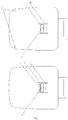
- a laser radar system 1 On a rail vehicle, a laser radar system 1, a camera system 2, a millimeterwave radar system 3 and a vehicle system 4 are installed at an end of the vehicle according to Fig. 1 .
- the detection ranges of the laser radar system 1, the camera system 2, and the millimeterwave radar system 3 are shown in Fig. 2 .
- Millimeterwave radar sensors use millimeterwave.
- the millimeterwave is in a frequency domain of 30-300 GHz (wavelength of 1-10 mm).
- the wavelength of millimeterwave is between those of centimeter wave and light wave, so the millimeterwave has the advantages of microwave guidance and photoelectric guidance.
- the millimeterwave radar Compared with centimeter wave radar, the millimeterwave radar has the characteristics of small size, easy integration and high spatial resolution. Its ranging principle is the same as that of general radar, that is, radio waves (radar waves) are sent out, then echoes are received, and position data of a target is measured according to the time difference between sending and receiving.
- radio waves radar waves
- the millimeterwave radar can complement a camera and a laser radar, and convert long-distance vehicles, road metal/stone/concrete obstacles in front of the vehicle into target information and send the target information to a decision-making and planning module. Especially under the conditions of bad weather and low visibility, it can make up for the shortcomings of a visual sensor.
- the wavelength of laser used in the radar system is usually only on the order of micrometers, so it can detect very tiny targets, and the measurement distance is much longer than that of millimeterwave radar and other vehicle-mounted standard radars.
- its precision is greatly affected by weathers such as rain, snow, fog, and sunlight, so its performance in rain and snow needs to be improved.
- a complete laser device should include three parts, a rotating mirror, a correction mirror, and a laser transmitting and receiving device.
- the laser transmitting and receiving device includes a transmitting unit and a receiving unit.
- Laser is transmitted by a diode, the laser is reflected to the rotating mirror by the correction mirror, and then the reflected laser is reflected to the correction mirror and finally to the receiving device. Because the rotating mirror has a rotating and well-designed structure, it can receive light within a range up to 180 degrees.
- the mirror can simply move up and down to form point clouds in the height direction.
- optical scanning laser radar is also a very common technology. It transmits laser to illuminate a large area to form a 2D focal plane array, as shown in Fig. 3 .
- the detection principle is, based on the return time, a photon detector is installed near the diode, and the distance of the target can be calculated from the time difference between transmission and detection. Meanwhile, a pulse measurement system can also collect a large number of point clouds after being activated, and a 2D image can also be generated from the point clouds.
- Radar image synchronization technology Considering different viewing angles and test ranges of radar images, and noise of intensity information due to coherent superposition of radar echo signals of multiple radar systems, a radar system and an imaging system need to be matched.
- Radar systems are subjected to superposition of echo signals and coherent superposition of signal waves, so multi-view processing is required, that is, De Grandi, Non-linear Diffusion filtering is utilized to avoid the interference of multiple radar systems.
- a camera installed at the front end of the vehicle captures information of the front of the vehicle, the laser emits multiple pulsed beams to form a 2D focal plane array, an image recognition range of a region of interest and a focal plane array range are selected, the plane and the camera are clipped by means of a central processing unit, and the edge is strengthened and corrected.
- the camera installed at the front end of the vehicle captures information of the front of the vehicle, and the millimeterwave radar detects obstacles in front. When a wave signal encounters an obstacle, it will be reflected. The distance of the obstacle is obtained according to the frequency difference.
- a 2D spectrogram region of interest and an image region of interest are selected, and the edge is strengthened and corrected.
- the specific operations are as follows: After the millimeterwave radar transmits and receives a 2D spectrogram, a distance distribution map can be obtained according to the distance. Considering the difference between the regions recognized by the millimeterwave radar and the video, a region of interest, that is, a region where the video system is superposed with the radar system, should be selected first. The biggest difficulty at present is edge selection, because it is difficult to match at edge points. Therefore, this method can supplement missing data by interpolation, fitting and data pre-cleaning, thereby ensuring the homogeneity of a data layer to the greatest extent.
- each sensor data is converted into a Bayesian estimate, and an optimal fusion number is determined through a neural network, so as to complete the matching of the edge.
- spots and decay during the image matching process possible spots and decay in images can be eliminated by means of mean filtering, median filtering or the like.
- the distance between a point in a 2D dot matrix recognized by laser and a vehicle is marked as X, then X 1 , X 2 ... are selected, and a distance variable ⁇ X is also selected.
- Points in [X 1 - ⁇ X, X 1 + ⁇ X], [X 2 - ⁇ X, X 2 + ⁇ X]... are selected in turn and denoted by different modules, 8 regions around the 5 th point as shown in the figure are determined, and if there are points of the same type, that is, points connected to the same distance module within the same module, points of the same distance module are obtained according to the continuity condition, then a plane is constituted based on these points as an obstacle.
- the laser image and distance parameters are transmitted to the central processing unit. 1 2 3 4 5 6 7 8 9
- X 1 , X 2 ... are selected, and a distance variable ⁇ X is also selected.
- Points in [X 1 - ⁇ X, X 1 + ⁇ X], [X 2 - ⁇ X, X 2 + ⁇ X]... are selected in turn and denoted by different modules, 8 regions around the 5 th point as shown in the figure are determined, and if there are points of the same type, that is, points connected to the same distance module within the same module, points of the same distance module are obtained according to the continuity condition, then a plane is constituted based on these points as an obstacle.
- the millimeterwave image and distance parameters are transmitted to the central processing unit.
- a threshold value is set according to the recognition distances, recognition regions, and recognition characteristics of the millimeterwave radar and the laser radar, that is, the laser image is used for the distance greater than a certain X, the millimeterwave image is used for the distance smaller than a certain X, and the laser radar is used as a reference. Finally, an obstacle is selected from the original image and its distance parameters are marked. Therefore, the recognition and detection on the distance of the obstacle are realized.
- the algorithm is relatively simple, a recognition region can be directly set for segmentation, and obstacle recognition and distance measurement can be achieved according to the above method.
- Curve regions are classified according to rail vehicles and urban trackless vehicles, and analyzed separately for rail vehicles and trackless vehicles.
- the curve For a rail vehicle, the curve should be judged according to a curve detection device at the rim, the recognition region should be adjusted appropriately, the distance of an obstacle is determined by a curve-based algorithm for the curve condition, and then the obstacle and distance in the driving direction of the vehicle are determined to determine a traction braking plan.
- the recognition region should be expanded. On the premise that the measurement region of the millimeterwave radar is wide, the recognition region can be expanded.
- the present invention combines the advantages of millimeterwave recognition technology and laser technology, explains how to eliminate interference, and projects obstacles onto images.
- the use of multiple radar systems to improve redundancy and their production are also inevitable requirements for the implementation of large-scale urban transportation systems, and this is an invention that can see results in a short time.
- the specific steps of the present invention are as follows:
Landscapes
- Engineering & Computer Science (AREA)
- Radar, Positioning & Navigation (AREA)
- Remote Sensing (AREA)
- Physics & Mathematics (AREA)
- Computer Networks & Wireless Communication (AREA)
- General Physics & Mathematics (AREA)
- Electromagnetism (AREA)
- Artificial Intelligence (AREA)
- Evolutionary Computation (AREA)
- Traffic Control Systems (AREA)
- Radar Systems Or Details Thereof (AREA)
Abstract
Description
- The present invention belongs to the field of traffic, and particularly relates to a method for detecting rail and road obstacles.
- The domestic mainstream obstacle detection technology is still in its infancy. Now the main rail transit obstacle detection technology still relies on a contact obstacle detection device arranged at the front end of a rail vehicle. This technology implements detection by mechanical means of touch, so its detection range is short and it does not have early warning capability. In addition, the current radar detection technology is not mature enough, especially when driving on turns and slopes, its detection precision and accuracy cannot meet the obstacle detection requirements of road traffic. Moreover, the number of laser scanning points is limited, and the scanning points are uneven and sparse, which easily causes the vehicle to be unable to identify obstacles where the point cloud is relatively sparse, and the sizes of the obstacles cannot be qualitatively estimated. At the same time, the millimeterwave radar is not mature, its precision and accuracy during long-distance detection are difficult to meet the requirements of automatic driving systems, and it takes a long time to upgrade a single radar system. With the development of unmanned driving technology and artificial intelligence technology, vehicles are bound to have early warning functions and automatic obstacle detection technology, which will rapidly spread throughout the fields of urban rail transit and trackless transportation in the foreseeable future. Therefore, the comprehensive use of multiple radar systems to detect obstacles will also become an urgent need in the era of autonomous driving technology and artificial intelligence.
- Aiming at the above shortcomings of the prior art, the purpose of the present invention is to provide a method for detecting rail and road obstacles based on laser radar, millimeterwave radar and image recognition, which can determine whether obstacles exist and detect the distance of an obstacle, thereby providing a basis for determining whether to implement braking or emergency braking by a control center.
- In order to solve the above technical problems, the technical solution adopted by the present invention is as follows:
A method for detecting rail and road obstacles, including the following steps: - Step A. acquiring an image in front of a vehicle by a monocular or multi-lens camera installed on the head of the rail vehicle;
- Step B. transmitting optical signals by a millimeterwave device and a laser device and receiving the optical signals by a photon detector to obtain a 2D point cloud image and a 2D spectrogram;
- Step C. performing multi-view processing on the images, and then matching laser radar and video systems by focal plane array analysis with the video system as a medium; for a millimeterwave radar, matching the video system with a millimeterwave radar system by data preprocessing and edge matching to complete pixel-level fusion of the laser radar, millimeterwave radar, and video systems; performing sequence analysis on the acquired images, performing filter processing on the multiple radar systems and the video system, and matching the images captured by the millimeterwave radar and the laser radar with the original image; and
- Step D. analyzing forward obstacles based on the characteristics of the millimeterwave radar and the laser radar, calculating weights by machine learning and adjusting parameters according to weather conditions, based on the recognition precision of the millimeterwave radar under extreme weather conditions (heavy rain (1d (or 24h), rainfall 100~250 mm), strong wind above level 7, heavy fog with visibility not more than 150 meters, strong sandstorm, or haze with PM2.0 above 500); under non-extreme severe weather conditions, segmenting objects according to their shapes by machine learning, and setting a threshold value by machine learning to strengthen the recognition weights of the laser radar; detecting some possible obscured objects by means of the penetrating ability of the millimeterwave radar; and setting a distance module to analyze possible obstacles in front of the vehicle, and marking the obstacles according to the characteristics of distance module points.
- Further, the method includes step E. marking parameters by the distance module for straight roads, curves, and ramps, and displaying the distance between an obstacle and a vehicle.
- Further, the method includes step F. obtaining the actual size of an obstacle according to the corresponding obstacle, the distance of the obstacle and the size of the obstacle on the image captured by the camera; when the actual size of the obstacle exceeds 30cm∗30cm∗30cm, decelerating the rail vehicle; and when the actual size of the obstacle exceeds 60cm∗60cm∗60cm, taking emergency braking on the rail vehicle. The present invention adopts the integrated technology of multiple radar systems and image recognition, comprehensively uses the advantages of image recognition, millimeterwave radar and laser radar, realizes ranging and obstacle determination through a vehicle device installed on the rail vehicle, and recognizes obstacles. The distance of an obstacle is determined by transmitting and receiving light beams, and the scanned results are synchronized to an image by means of a block diagram. Finally, whether to implement braking or emergency braking is determined in the control center according to the distance and the size of the obstacle, so as to realize the requirements of early warning and safety improvement of rail vehicles, and improve the safety of unmanned driving.
- The present invention can recognize obstacles more accurately, and has certain early warning function. Compared with the existing detection method, the method of the present invention can simultaneously ensure accuracy and early warning function.
-
-
Fig. 1 is a schematic installation diagram of a laser radar system, a camera system, a millimeterwave radar system and a vehicle-mounted system in the method of the present invention. -
Fig. 2 is a schematic diagram of detection ranges of the laser radar system, the camera system, and the millimeterwave radar system in the method of the present invention. -
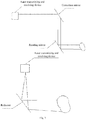
Fig. 3 is a schematic diagram of optical scanning laser radar. - The principle of the present invention is prepared as follows:
- On a rail vehicle, a laser radar system 1, a
camera system 2, amillimeterwave radar system 3 and avehicle system 4 are installed at an end of the vehicle according toFig. 1 . The detection ranges of the laser radar system 1, thecamera system 2, and themillimeterwave radar system 3 are shown inFig. 2 . - Millimeterwave radar sensors use millimeterwave. Generally, the millimeterwave is in a frequency domain of 30-300 GHz (wavelength of 1-10 mm). The wavelength of millimeterwave is between those of centimeter wave and light wave, so the millimeterwave has the advantages of microwave guidance and photoelectric guidance.
- Compared with centimeter wave radar, the millimeterwave radar has the characteristics of small size, easy integration and high spatial resolution. Its ranging principle is the same as that of general radar, that is, radio waves (radar waves) are sent out, then echoes are received, and position data of a target is measured according to the time difference between sending and receiving.
- The millimeterwave radar can complement a camera and a laser radar, and convert long-distance vehicles, road metal/stone/concrete obstacles in front of the vehicle into target information and send the target information to a decision-making and planning module. Especially under the conditions of bad weather and low visibility, it can make up for the shortcomings of a visual sensor.
- Laser beam detection technology:
Laser radar is a radar system that emits a laser beam to detect characteristic quantities such as position and speed of a target. Its working principle is, a detection signal (laser beam) is transmitted to the target, then the received signal (target echo) reflected from the target is compared with the transmitted signal to match the transmitted signal with the recovered signal, the time Δt is calculated, and s=v∗Δt can be obtained according to the speed; meanwhile, each laser point transmitted is matched to an image, and information such as orientation, height, posture and shape can be obtained according to the number of point clouds and their positions on the image; in addition, a speed parameter of the front vehicle can be obtained according to the speed of the vehicle and the distance difference of two detections; therefore, the laser radar can obtain relevant information of the target, such as target distance, orientation, height, speed, posture, and even shape. - The wavelength of laser used in the radar system is usually only on the order of micrometers, so it can detect very tiny targets, and the measurement distance is much longer than that of millimeterwave radar and other vehicle-mounted standard radars. However, its precision is greatly affected by weathers such as rain, snow, fog, and sunlight, so its performance in rain and snow needs to be improved.
- A complete laser device should include three parts, a rotating mirror, a correction mirror, and a laser transmitting and receiving device. The laser transmitting and receiving device includes a transmitting unit and a receiving unit. Laser is transmitted by a diode, the laser is reflected to the rotating mirror by the correction mirror, and then the reflected laser is reflected to the correction mirror and finally to the receiving device. Because the rotating mirror has a rotating and well-designed structure, it can receive light within a range up to 180 degrees.
- As a unique movement mechanism, the mirror can simply move up and down to form point clouds in the height direction.
- In addition, optical scanning laser radar is also a very common technology. It transmits laser to illuminate a large area to form a 2D focal plane array, as shown in
Fig. 3 . - The detection principle is, based on the return time, a photon detector is installed near the diode, and the distance of the target can be calculated from the time difference between transmission and detection. Meanwhile, a pulse measurement system can also collect a large number of point clouds after being activated, and a 2D image can also be generated from the point clouds.
- Radar image synchronization technology:
Considering different viewing angles and test ranges of radar images, and noise of intensity information due to coherent superposition of radar echo signals of multiple radar systems, a radar system and an imaging system need to be matched. - Radar systems are subjected to superposition of echo signals and coherent superposition of signal waves, so multi-view processing is required, that is, De Grandi, Non-linear Diffusion filtering is utilized to avoid the interference of multiple radar systems.
- A camera installed at the front end of the vehicle captures information of the front of the vehicle, the laser emits multiple pulsed beams to form a 2D focal plane array, an image recognition range of a region of interest and a focal plane array range are selected, the plane and the camera are clipped by means of a central processing unit, and the edge is strengthened and corrected.
- The camera installed at the front end of the vehicle captures information of the front of the vehicle, and the millimeterwave radar detects obstacles in front. When a wave signal encounters an obstacle, it will be reflected. The distance of the obstacle is obtained according to the frequency difference. The formula is as follows:

- R: target distance
- td: delay time
- C: speed of light
- According to the Doppler effect and the triangular waveform, it can be obtained:

- f b-: falling frequency
- f b+: rising frequency
- t m: time
- ΔF: bandwidth of the transmitted signal
- A 2D spectrogram region of interest and an image region of interest are selected, and the edge is strengthened and corrected. The specific operations are as follows:
After the millimeterwave radar transmits and receives a 2D spectrogram, a distance distribution map can be obtained according to the distance. Considering the difference between the regions recognized by the millimeterwave radar and the video, a region of interest, that is, a region where the video system is superposed with the radar system, should be selected first. The biggest difficulty at present is edge selection, because it is difficult to match at edge points. Therefore, this method can supplement missing data by interpolation, fitting and data pre-cleaning, thereby ensuring the homogeneity of a data layer to the greatest extent. - At the same time, each sensor data is converted into a Bayesian estimate, and an optimal fusion number is determined through a neural network, so as to complete the matching of the edge.
- Considering spots and decay during the image matching process, possible spots and decay in images can be eliminated by means of mean filtering, median filtering or the like.
- The distance between a point in a 2D dot matrix recognized by laser and a vehicle is marked as X, then X1, X2... are selected, and a distance variable ΔX is also selected.
- Points in [X1-ΔX, X1+ΔX], [X2-ΔX, X2+ΔX]... are selected in turn and denoted by different modules, 8 regions around the 5th point as shown in the figure are determined, and if there are points of the same type, that is, points connected to the same distance module within the same module, points of the same distance module are obtained according to the continuity condition, then a plane is constituted based on these points as an obstacle. At the same time, the laser image and distance parameters are transmitted to the central processing unit.
1 2 3 4 5 6 7 8 9 - Similarly, the distance between each pixel in a 2D spectrogram recognized by millimeterwave and a vehicle is marked as X, then X1, X2... are selected, and a distance variable ΔX is also selected.
- Points in [X1-ΔX, X1+ΔX], [X2-ΔX, X2+ΔX]... are selected in turn and denoted by different modules, 8 regions around the 5th point as shown in the figure are determined, and if there are points of the same type, that is, points connected to the same distance module within the same module, points of the same distance module are obtained according to the continuity condition, then a plane is constituted based on these points as an obstacle. At the same time, the millimeterwave image and distance parameters are transmitted to the central processing unit.
- After the laser image, the millimeterwave image and the distance parameters are received, a threshold value is set according to the recognition distances, recognition regions, and recognition characteristics of the millimeterwave radar and the laser radar, that is, the laser image is used for the distance greater than a certain X, the millimeterwave image is used for the distance smaller than a certain X, and the laser radar is used as a reference. Finally, an obstacle is selected from the original image and its distance parameters are marked. Therefore, the recognition and detection on the distance of the obstacle are realized.
- In a straight region, the algorithm is relatively simple, a recognition region can be directly set for segmentation, and obstacle recognition and distance measurement can be achieved according to the above method.
- Curve regions are classified according to rail vehicles and urban trackless vehicles, and analyzed separately for rail vehicles and trackless vehicles. For a rail vehicle, the curve should be judged according to a curve detection device at the rim, the recognition region should be adjusted appropriately, the distance of an obstacle is determined by a curve-based algorithm for the curve condition, and then the obstacle and distance in the driving direction of the vehicle are determined to determine a traction braking plan. For a trackless vehicle in the curve region, the recognition region should be expanded. On the premise that the measurement region of the millimeterwave radar is wide, the recognition region can be expanded. Due to the detection dead angle of the laser radar, potential obstacles on the way are prejudged by means of a millimeterwave radar and a binocular camera, thereby recognizing the obstacles in a wider range and determining their distances. According to the wiedemann99 vehicle-following model discrimination, braking instructions are implemented to ensure vehicle safety.
- Due to the vigorous development of unmanned driving and intelligent driving technology, it is bound to require future urban vehicles and rail vehicles to have the ability to automatically recognize obstacles. The present invention combines the advantages of millimeterwave recognition technology and laser technology, explains how to eliminate interference, and projects obstacles onto images. In addition, considering the safety, the use of multiple radar systems to improve redundancy and their production are also inevitable requirements for the implementation of large-scale urban transportation systems, and this is an invention that can see results in a short time. The specific steps of the present invention are as follows:
- Step A. Acquisition of a real-time image: an image in front of a vehicle is acquired by a monocular or multi-lens camera installed on the head of the rail vehicle, wherein the camera is an optical anti-shake camera with ultra-long focal length.
- Step B. Collection of real-time optical signals: optical signals are transmitted by a millimeterwave device and a laser device and received by a photon detector to obtain a 2D point cloud image and a 2D spectrogram.
- Step C. Pre-processing and pre-matching of the images: multi-view processing is performed on the images, that is, De Grandi, Non-linear Diffusion filtering is performed to avoid radar interference, and then laser radar and video systems are matched by focal plane array analysis with an image system as a medium; for a millimeterwave radar, a video system is matched with a millimeterwave radar system by data preprocessing and edge matching to complete pixel-level fusion of the laser radar, millimeterwave radar, and video systems; sequence analysis is performed on the acquired images, filter processing is performed on the multiple radar systems and the video system, and the images captured by the millimeterwave radar and the laser radar are matched with the original image. Therefore, the amount of calculation for direct matching of multiple systems is reduced, and the pre-matching is also more accurate than simple coordinate matching.
- Step D. Determination of obstacles: forward obstacles are analyzed based on the characteristics of the millimeterwave radar and the laser radar; considering that the millimeterwave radar has high recognition precision in bad and extreme weather (heavy rain (1d (or 24h), rainfall 100~250 mm), strong wind above level 7, heavy fog with visibility not more than 150 meters, strong sandstorm, and haze with PM2.0 above 500), weights are calculated by machine learning and parameters are adjusted under extreme weather conditions, based on the recognition of the millimeterwave radar; under non-extreme severe weather conditions, objects are segmented according to their shapes by machine learning, and a threshold value is set by machine learning to strengthen the recognition weights of the laser radar, based on the recognition of the laser radar; some possible obscured objects are detected by means of the penetrating ability of the millimeterwave radar to realize early warning, which is extremely effective for collision avoidance system of trams; a distance module is set to analyze possible obstacles in front of the vehicle, and the obstacles are marked according to the characteristics of distance module points.
- Step E. Determination of a distance: parameters are marked by the distance module for straight roads, curves, and ramps, and the distance between an obstacle and a vehicle is displayed.
- Step F. Recognition of an obstacle and measures taken: the actual size of an obstacle is obtained according to the corresponding obstacle, the distance of the obstacle and the size of the obstacle on the image captured by the camera; from practical experience, when the actual size of the obstacle exceeds 30cm∗30cm∗30cm, it is considered to affect the normal passage of a rail vehicle, and the control center will decelerate the rail vehicle; when the actual size of the obstacle exceeds 60cm∗60cm∗60cm, it is considered that the obstacle will cause the train to derail or cause a major traffic accident, and the control center will take emergency braking on the rail vehicle. In urban traffic, traction and braking are performed according to the Wiedemann99 driving behavior model.
- The embodiments of the present invention are described above with reference to the drawings, but the present invention is not limited to the specific embodiments. The specific embodiments described above are merely illustrative but not restrictive. Many forms may also be made by those of ordinary skill in the art under the enlightenment of the present invention without departing from the purpose of the present invention and the scope of the claims, and these forms fall into the scope of the present invention.
Claims (3)
- A method for detecting rail and road obstacles, comprising the following steps:step A. acquiring an image in front of a vehicle by a monocular or multi-lens camera installed on the head of the rail vehicle;step B. transmitting optical signals by a millimeterwave device and a laser device and receiving the optical signals by a photon detector to obtain a 2D point cloud image and a 2D spectrogram;step C. performing multi-view processing on the images, and then matching laser radar and video systems by focal plane array analysis with the video system as a medium; for a millimeterwave radar, matching the video system with a millimeterwave radar system by data preprocessing and edge matching to complete pixel-level fusion of the laser radar, millimeterwave radar, and video systems; performing sequence analysis on the acquired images, performing filter processing on the multiple radar systems and the video system, and matching the images captured by the millimeterwave radar and the laser radar with the original image; andstep D. analyzing forward obstacles based on the characteristics of the millimeterwave radar and the laser radar, calculating weights by machine learning and adjusting parameters according to weather conditions, based on the recognition precision of the millimeterwave radar under extreme weather conditions; under non-extreme severe weather conditions, segmenting objects according to their shapes by machine learning, and setting a threshold value by machine learning to strengthen the recognition weights of the laser radar; detecting some possible obscured objects by means of the penetrating ability of the millimeterwave radar; and setting a distance module to analyze possible obstacles in front of the vehicle, and marking the obstacles according to the characteristics of distance module points.
- The method for detecting rail and road obstacles according to claim 1, further comprising:
step E. marking parameters by the distance module for straight roads, curves, and ramps, and displaying the distance between an obstacle and a vehicle. - The method for detecting rail and road obstacles according to claim 2, further comprising:
step F. obtaining the actual size of an obstacle according to the corresponding obstacle, the distance of the obstacle and the size of the obstacle on the image captured by the camera; when the actual size of the obstacle exceeds 30cm∗30cm∗30cm, decelerating the rail vehicle; and when the actual size of the obstacle exceeds 60cm∗60cm∗60cm, taking emergency braking on the rail vehicle.
Applications Claiming Priority (2)
| Application Number | Priority Date | Filing Date | Title |
|---|---|---|---|
| CN201811382843.7A CN109298415B (en) | 2018-11-20 | 2018-11-20 | Method for detecting obstacles on track and road |
| PCT/CN2019/104841 WO2020103533A1 (en) | 2018-11-20 | 2019-09-09 | Track and road obstacle detecting method |
Publications (2)
| Publication Number | Publication Date |
|---|---|
| EP3885794A1 true EP3885794A1 (en) | 2021-09-29 |
| EP3885794A4 EP3885794A4 (en) | 2022-08-17 |
Family
ID=65143466
Family Applications (1)
| Application Number | Title | Priority Date | Filing Date |
|---|---|---|---|
| EP19886098.3A Withdrawn EP3885794A4 (en) | 2018-11-20 | 2019-09-09 | Track and road obstacle detecting method |
Country Status (3)
| Country | Link |
|---|---|
| EP (1) | EP3885794A4 (en) |
| CN (1) | CN109298415B (en) |
| WO (1) | WO2020103533A1 (en) |
Cited By (2)
| Publication number | Priority date | Publication date | Assignee | Title |
|---|---|---|---|---|
| CN114037972A (en) * | 2021-10-08 | 2022-02-11 | 岚图汽车科技有限公司 | Target detection method, device, equipment and readable storage medium |
| CN114550142A (en) * | 2022-04-25 | 2022-05-27 | 深圳佑驾创新科技有限公司 | Parking space detection method based on fusion of 4D millimeter wave radar and image recognition |
Families Citing this family (109)
| Publication number | Priority date | Publication date | Assignee | Title |
|---|---|---|---|---|
| CN109298415B (en) * | 2018-11-20 | 2020-09-22 | 中车株洲电力机车有限公司 | Method for detecting obstacles on track and road |
| CN111688758A (en) * | 2019-03-11 | 2020-09-22 | 北京华通时空通信技术有限公司 | Obstacle detection system for high-speed railway track |
| CN119693896A (en) | 2019-06-18 | 2025-03-25 | 深圳引望智能技术有限公司 | Method and device for determining driving area information |
| CN110287897B (en) * | 2019-06-27 | 2021-05-14 | 清华大学 | Rail train visual positioning system based on deep learning |
| CN110239592A (en) * | 2019-07-03 | 2019-09-17 | 中铁轨道交通装备有限公司 | A kind of active barrier of rail vehicle and derailing detection system |
| CN110412563A (en) * | 2019-07-29 | 2019-11-05 | 哈尔滨工业大学 | A kind of Portable distance meter and its working method of the auxiliary train railway carriage mounting based on Multi-sensor Fusion |
| CN110412986A (en) * | 2019-08-19 | 2019-11-05 | 中车株洲电力机车有限公司 | A kind of vehicle barrier detection method and system |
| US11378652B2 (en) * | 2019-09-03 | 2022-07-05 | GM Global Technology Operations LLC | Enhancement of vehicle radar system robustness based on elevation information |
| CN110542909B (en) * | 2019-09-03 | 2022-04-15 | 北京领骏科技有限公司 | Atmospheric visibility detection method and electronic equipment |
| CN110596731A (en) * | 2019-09-12 | 2019-12-20 | 天津市市政工程设计研究院 | An active obstacle detection system and method for subway vehicles |
| CN110717477A (en) * | 2019-10-22 | 2020-01-21 | 深圳市微度数字技术有限公司 | Intelligent early warning and analyzing device for track |
| CN110866544B (en) * | 2019-10-28 | 2022-04-15 | 杭州飞步科技有限公司 | Sensor data fusion method and device and storage medium |
| TWI809241B (en) * | 2020-01-16 | 2023-07-21 | 為昇科科技股份有限公司 | Life form radar system, identification method, and database establishment method |
| CN113734207B (en) * | 2020-05-29 | 2023-06-13 | 比亚迪股份有限公司 | Vehicle safety protection system, method and vehicle |
| CN111661111A (en) * | 2020-06-03 | 2020-09-15 | 深圳市视晶无线技术有限公司 | Rail transit obstacle detection method and device |
| CN111723724B (en) * | 2020-06-16 | 2024-04-02 | 东软睿驰汽车技术(沈阳)有限公司 | Road surface obstacle recognition method and related device |
| CN111696390B (en) * | 2020-06-23 | 2023-01-20 | 五冶集团上海有限公司 | Intelligent airport runway FOD device and working process thereof |
| CN111880196A (en) * | 2020-06-29 | 2020-11-03 | 安徽海博智能科技有限责任公司 | Unmanned mine car anti-interference method, system and computer equipment |
| CN111781606A (en) * | 2020-07-02 | 2020-10-16 | 大唐信通(浙江)科技有限公司 | A new miniaturization method for fusion of lidar and ultrasonic radar |
| CN112009524B (en) * | 2020-07-15 | 2022-06-07 | 北京埃福瑞科技有限公司 | System and method for tramcar obstacle detection |
| CN111856417B (en) * | 2020-07-20 | 2023-07-21 | 中国第一汽车股份有限公司 | Performance analysis method, device, terminal and storage medium of vehicle millimeter wave radar |
| CN114167443B (en) * | 2020-08-19 | 2025-03-07 | 北京万集科技股份有限公司 | Information completion method, device, computer equipment and storage medium |
| CN112285700B (en) * | 2020-08-24 | 2023-12-15 | 江苏大学 | Maneuvering target tracking method based on the fusion of lidar and millimeter wave radar |
| CN112285714B (en) * | 2020-09-08 | 2024-08-02 | 苏州挚途科技有限公司 | Obstacle speed fusion method and device based on multiple sensors |
| CN112307594B (en) * | 2020-09-22 | 2023-03-28 | 中国汽车技术研究中心有限公司 | Road data acquisition and simulation scene establishment integrated system and method |
| CN114379545B (en) * | 2020-10-16 | 2024-02-02 | 上海汽车集团股份有限公司 | Anti-collision method and device for vehicle |
| CN112380927B (en) * | 2020-10-29 | 2023-06-30 | 中车株洲电力机车研究所有限公司 | Rail identification method and device |
| CN112415517A (en) * | 2020-11-03 | 2021-02-26 | 上海泽高电子工程技术股份有限公司 | Rail identification method based on millimeter wave radar |
| CN112053565B (en) * | 2020-11-09 | 2021-04-20 | 江苏量动信息科技有限公司 | Laser radar identification system |
| CN112415518B (en) * | 2020-11-20 | 2023-09-26 | 南京理工大学 | Passable space detection method based on vehicle-mounted millimeter wave radar |
| CN112487919A (en) * | 2020-11-25 | 2021-03-12 | 吉林大学 | 3D target detection and tracking method based on camera and laser radar |
| CN112464812B (en) * | 2020-11-27 | 2023-11-24 | 西北工业大学 | A vehicle-based sunken obstacle detection method |
| CN112330746A (en) * | 2020-11-27 | 2021-02-05 | 苏州感测通信息科技有限公司 | A mobile chassis obstacle detection method based on TX2 |
| CN112541416B (en) * | 2020-12-02 | 2023-07-14 | 深兰科技(上海)有限公司 | Cross-radar obstacle tracking method, device, electronic equipment and storage medium |
| CN114594433B (en) * | 2020-12-03 | 2025-03-18 | 中国人民解放军63963部队 | Millimeter wave radar performance testing device and testing method |
| CN112698302B (en) * | 2020-12-16 | 2023-11-07 | 南京航空航天大学 | A sensor fusion target detection method under bumpy road conditions |
| CN112835030A (en) * | 2020-12-30 | 2021-05-25 | 深圳承泰科技有限公司 | A data fusion method, device and smart car for obstacle target |
| CN114690260A (en) * | 2020-12-31 | 2022-07-01 | 同方威视技术股份有限公司 | Vehicle safety inspection system and safety inspection method |
| CN112946627B (en) * | 2021-01-29 | 2024-03-22 | 中汽创智科技有限公司 | Millimeter wave radar detection system and method based on visual information |
| CN112965054B (en) * | 2021-02-03 | 2023-09-19 | 南京众控电子科技有限公司 | Cabin door opening and closing recognition method based on radar technology |
| CN115047474A (en) * | 2021-03-09 | 2022-09-13 | 信泰光学(深圳)有限公司 | Distance measuring method and distance measuring device |
| CN113030866B (en) * | 2021-03-12 | 2023-06-06 | 中国铁道科学研究院集团有限公司 | Method and device for determining state of railway crushed stone bed based on radar electromagnetic signal |
| CN112977541A (en) * | 2021-03-17 | 2021-06-18 | 上海电气泰雷兹交通自动化系统有限公司 | Train protection early warning system based on multi-technology fusion |
| CN113050654A (en) * | 2021-03-29 | 2021-06-29 | 中车青岛四方车辆研究所有限公司 | Obstacle detection method, vehicle-mounted obstacle avoidance system and method for inspection robot |
| CN113189591B (en) * | 2021-03-31 | 2024-04-09 | 苏州理工雷科传感技术有限公司 | A vehicle-mounted detection system for detecting small targets on the road surface |
| CN113110434B (en) * | 2021-04-06 | 2022-04-19 | 中国矿业大学 | A cockpit-less underground unmanned electric locomotive and its control method |
| CN113156421A (en) * | 2021-04-07 | 2021-07-23 | 南京邮电大学 | Obstacle detection method based on information fusion of millimeter wave radar and camera |
| CN113189581A (en) * | 2021-04-09 | 2021-07-30 | 同济大学 | Millimeter wave radar and visual fusion fog penetration target recognition algorithm processing method |
| CN113282982B (en) * | 2021-04-30 | 2023-04-18 | 杭州申昊科技股份有限公司 | System and method for evaluating safety of rail based on mud spraying condition |
| CN113375563B (en) * | 2021-05-12 | 2023-04-28 | 深圳市北斗云信息技术有限公司 | Landslide displacement monitoring method and system by fusing laser LIDAR and video |
| CN115236672A (en) * | 2021-05-12 | 2022-10-25 | 上海仙途智能科技有限公司 | Obstacle information generation method, device, equipment and computer readable storage medium |
| CN113466853B (en) * | 2021-06-24 | 2024-05-10 | 山东科技大学 | Obstacle detection device before moving of advanced hydraulic support group |
| CN113470354A (en) * | 2021-06-24 | 2021-10-01 | 上海智能网联汽车技术中心有限公司 | All-weather road test sensing system |
| CN113568002A (en) * | 2021-06-24 | 2021-10-29 | 中车南京浦镇车辆有限公司 | Rail transit active obstacle detection device based on laser and image data fusion |
| CN113469130B (en) * | 2021-07-23 | 2024-11-05 | 浙江大华技术股份有限公司 | A method, device, storage medium and electronic device for detecting an obstructed target |
| CN113609942B (en) * | 2021-07-27 | 2022-11-22 | 数量级(上海)信息技术有限公司 | Road intelligent monitoring system based on multi-view and multi-spectral fusion |
| CN113671491A (en) * | 2021-08-16 | 2021-11-19 | 珠海格力电器股份有限公司 | A road condition detection and early warning method and device |
| CN113917476A (en) * | 2021-08-31 | 2022-01-11 | 际络科技(上海)有限公司 | Speed measurement method and device and electronic equipment |
| CN113777622B (en) * | 2021-08-31 | 2023-10-20 | 通号城市轨道交通技术有限公司 | Rail obstacle identification method and device |
| CN113820714B (en) * | 2021-09-07 | 2024-04-12 | 重庆驰知科技有限公司 | A road environment perception system in dusty and foggy weather based on multi-sensor fusion |
| CN113799852B (en) * | 2021-09-22 | 2022-12-02 | 天津津航计算技术研究所 | Intelligent active obstacle identification protection method supporting dynamic mode switching |
| CN113687349A (en) * | 2021-09-23 | 2021-11-23 | 上海大学 | Unmanned ship sea surface target tracking method and device based on multi-sensor fusion |
| CN113884090A (en) * | 2021-09-28 | 2022-01-04 | 中国科学技术大学先进技术研究院 | Intelligent platform vehicle environment sensing system and data fusion method thereof |
| CN113759365B (en) * | 2021-10-11 | 2024-05-31 | 内蒙古方向图科技有限公司 | Binocular vision three-dimensional optical image and foundation radar data fusion method and system |
| CN114022760B (en) * | 2021-10-14 | 2022-08-05 | 湖南北斗微芯产业发展有限公司 | Railway tunnel barrier monitoring and early warning method, system, equipment and storage medium |
| CN114035187B (en) * | 2021-10-26 | 2024-08-23 | 北京国家新能源汽车技术创新中心有限公司 | Perception fusion method of automatic driving system |
| CN113868885B (en) * | 2021-11-01 | 2025-04-25 | 南京楚航科技有限公司 | A method for millimeter wave radar scene reproduction and data parameter adjustment based on Ethernet |
| CN116243295A (en) * | 2021-12-08 | 2023-06-09 | 致伸科技股份有限公司 | monitoring method |
| CN114397672A (en) * | 2021-12-14 | 2022-04-26 | 卡斯柯信号有限公司 | Train active obstacle detection method and device based on positioning technology |
| CN114013433B (en) * | 2021-12-24 | 2023-12-05 | 东风悦享科技有限公司 | Millimeter wave radar self-adaptive adjustment method based on high-precision map |
| CN114355337A (en) * | 2021-12-31 | 2022-04-15 | 北京太格时代自动化系统设备有限公司 | Railway construction limit-invasion early warning system based on 24GHz millimeter wave radar technology |
| CN114578345A (en) * | 2022-01-28 | 2022-06-03 | 南京司凯奇汽车科技有限公司 | An unmanned mine card obstacle detection system |
| CN114563788B (en) * | 2022-02-17 | 2024-08-27 | 英博超算(南京)科技有限公司 | Unmanned system based on single-line laser radar and millimeter wave radar |
| CN114363582B (en) * | 2022-03-15 | 2022-06-10 | 深圳中慧轨道智能科技有限公司 | Integrated track inspection vehicle image processing system |
| CN114739451A (en) * | 2022-03-22 | 2022-07-12 | 国网山东省电力公司超高压公司 | Transmission conductor safety early warning method under millimeter wave radar monitoring |
| CN114660607A (en) * | 2022-03-30 | 2022-06-24 | 徐工集团工程机械股份有限公司科技分公司 | A loader obstacle detection system and method |
| CN114942437B (en) * | 2022-04-25 | 2024-10-29 | 东风汽车集团股份有限公司 | A method for detecting a target on the front side of a vehicle ahead |
| CN114918915B (en) * | 2022-05-09 | 2023-12-12 | 高辰曦 | Escalator laser identification anti-falling device and algorithm thereof |
| CN114715152A (en) * | 2022-05-17 | 2022-07-08 | 厦门金龙联合汽车工业有限公司 | Vehicle formation method based on perception safety redundancy |
| CN114966631B (en) * | 2022-05-19 | 2025-02-07 | 安徽蔚来智驾科技有限公司 | Fault diagnosis and treatment method, device, medium and vehicle for vehicle-mounted laser radar |
| CN115128599B (en) * | 2022-06-10 | 2025-05-06 | 中国兵器科学研究院 | A building visualization imaging system, method, device, equipment and medium |
| CN115311850A (en) * | 2022-07-15 | 2022-11-08 | 重庆长安汽车股份有限公司 | Sprinkler identification and early warning method and system based on crowdsourcing mode |
| CN115421136A (en) * | 2022-07-28 | 2022-12-02 | 广西北投信创科技投资集团有限公司 | Vehicle detection system and detection method thereof |
| CN115320489A (en) * | 2022-08-11 | 2022-11-11 | 岚图汽车科技有限公司 | Night vehicle driving light control method and control system |
| CN115407755B (en) * | 2022-08-29 | 2025-07-22 | 环形山(武汉)科技有限公司 | Controller testing method and system for semi-active damping shock absorber |
| CN115330841A (en) * | 2022-08-31 | 2022-11-11 | 南京慧尔视智能科技有限公司 | Method, apparatus, device and medium for detecting projectile based on radar map |
| CN116461571B (en) * | 2022-09-20 | 2024-06-18 | 江苏中车数字科技有限公司 | Obstacle sensing system based on vision, radio frequency positioning and multi-line laser fusion |
| CN116008997A (en) * | 2022-09-22 | 2023-04-25 | 浙江零跑科技股份有限公司 | A parking space detection obstacle edge location method based on ultrasonic radar |
| CN115343698B (en) * | 2022-09-29 | 2025-05-02 | 江西索利得测量仪器有限公司 | Millimeter wave ranging optimization method and system |
| CN115503696A (en) * | 2022-10-26 | 2022-12-23 | 长安大学 | Unmanned automobile obstacle identification method and device |
| CN115755094A (en) * | 2022-11-29 | 2023-03-07 | 重庆赛迪奇智人工智能科技有限公司 | Obstacle detection method, device, equipment and storage medium |
| CN115616560B (en) * | 2022-12-02 | 2023-04-14 | 广汽埃安新能源汽车股份有限公司 | Vehicle obstacle avoidance method and device, electronic equipment and computer readable medium |
| CN116362994B (en) * | 2023-02-13 | 2025-11-04 | 上海电科智能系统股份有限公司 | A method for processing radar-visual fusion data on highways |
| CN118810702B (en) * | 2023-04-18 | 2026-02-10 | 比亚迪股份有限公司 | A control method, electronic equipment and vehicle for automatic emergency braking of a vehicle |
| CN116430396B (en) * | 2023-04-19 | 2026-03-13 | 河北博士林科技开发有限公司 | A high-precision method for locating road traffic safety hazards |
| CN116626669B (en) * | 2023-05-11 | 2025-10-24 | 集美大学 | Device and method for fusing radar imaging and video images |
| CN116654047A (en) * | 2023-06-13 | 2023-08-29 | 通号城市轨道交通技术有限公司 | Train control method, system and train in wet rail mode |
| CN116872829A (en) * | 2023-07-27 | 2023-10-13 | 高邮市华声电子有限公司 | An intelligent switching system for high and low beams of automobile headlights |
| CN117129975B (en) * | 2023-08-14 | 2024-08-16 | 深圳承泰科技有限公司 | Automatic radar alarm test method and system based on laser radar true value |
| CN117471463B (en) * | 2023-10-30 | 2025-07-11 | 合肥工大高科信息科技股份有限公司 | Obstacle detection method based on 4D radar and image recognition fusion |
| CN117590358B (en) * | 2024-01-15 | 2024-04-05 | 吉林瑞电科技有限公司 | Obstacle detection equipment with flange type sealing cover structure |
| CN118004900B (en) * | 2024-04-08 | 2024-06-07 | 山东朝辉自动化科技有限责任公司 | Portal crane security protection system based on visual monitoring |
| CN118226457B (en) * | 2024-05-27 | 2024-09-17 | 同济大学 | Pavement disease amount accurate statistical method based on single-point laser ranging radar |
| CN120044517B (en) * | 2025-04-18 | 2025-07-15 | 广州万协通信息技术有限公司 | Target identification method and system based on space-time fusion of radar data and camera data |
| CN120003561A (en) * | 2025-04-21 | 2025-05-16 | 北京全路通信信号研究设计院集团有限公司 | A safety early warning method, system, equipment and medium for railway shunting operation |
| CN120143309B (en) * | 2025-05-13 | 2025-07-11 | 华云升达(北京)气象科技有限责任公司 | Space continuous visibility prediction method and device based on multi-mode data analysis |
| CN120742298B (en) * | 2025-09-08 | 2025-11-21 | 中联德冠科技(北京)有限公司 | A UAV positioning and tracking method and system based on the fusion of millimeter-wave and optoelectronic spatiotemporal data |
| CN120802246B (en) * | 2025-09-12 | 2025-11-14 | 上海腾盛智能安全科技股份有限公司 | Data fusion method and device based on multiple sensors |
| CN121626129B (en) * | 2026-02-04 | 2026-05-01 | 临工重机股份有限公司 | Vehicle running control method and device, mine car, storage medium and product |
Family Cites Families (18)
| Publication number | Priority date | Publication date | Assignee | Title |
|---|---|---|---|---|
| JPH09264954A (en) * | 1996-03-29 | 1997-10-07 | Fujitsu Ten Ltd | Image processing system using radar |
| JP2007310741A (en) * | 2006-05-19 | 2007-11-29 | Fuji Heavy Ind Ltd | 3D object recognition device |
| CN101430377B (en) * | 2008-11-18 | 2011-06-22 | 北京航空航天大学 | APD array-based non-scanning 3D imaging lidar optical system |
| JP5538655B2 (en) * | 2011-03-25 | 2014-07-02 | 三菱電機株式会社 | In-vehicle radar system |
| CN103176185B (en) * | 2011-12-26 | 2015-01-21 | 上海汽车集团股份有限公司 | Method and system for detecting road barrier |
| CN102963322B (en) * | 2012-09-22 | 2015-04-22 | 仲玥 | Automobile driving environment detecting device and working process thereof |
| CN104199034A (en) * | 2014-09-19 | 2014-12-10 | 黄国鹏 | Radar sensor based automobile collision avoidance method and device |
| CN104290745B (en) * | 2014-10-28 | 2017-02-01 | 奇瑞汽车股份有限公司 | Driving method of semi-automatic driving system for vehicle |
| SE539893C2 (en) * | 2015-10-13 | 2018-01-02 | Qamcom Tech Ab | Radar method and system for monitoring a region of interest |
| US10353053B2 (en) * | 2016-04-22 | 2019-07-16 | Huawei Technologies Co., Ltd. | Object detection using radar and machine learning |
| CN106394513A (en) * | 2016-09-28 | 2017-02-15 | 鄂尔多斯市普渡科技有限公司 | Traveling device and strategy for driverless vehicle in rainy and snowy weather |
| CN106646474A (en) * | 2016-12-22 | 2017-05-10 | 中国兵器装备集团自动化研究所 | An unstructured road bumpy obstacle detection device |
| CN107230389A (en) * | 2017-07-26 | 2017-10-03 | 山西省交通科学研究院 | A kind of mountain area winding road safety pre-warning system and method |
| CN107499262A (en) * | 2017-10-17 | 2017-12-22 | 芜湖伯特利汽车安全系统股份有限公司 | ACC/AEB systems and vehicle based on machine learning |
| CN107909010B (en) * | 2017-10-27 | 2022-03-18 | 北京中科慧眼科技有限公司 | Road obstacle detection method and device |
| CN107991671A (en) * | 2017-11-23 | 2018-05-04 | 浙江东车智能科技有限公司 | A kind of method based on radar data and vision signal fusion recognition risk object |
| CN108416257A (en) * | 2018-01-19 | 2018-08-17 | 北京交通大学 | Merge the underground railway track obstacle detection method of vision and laser radar data feature |
| CN109298415B (en) * | 2018-11-20 | 2020-09-22 | 中车株洲电力机车有限公司 | Method for detecting obstacles on track and road |
-
2018
- 2018-11-20 CN CN201811382843.7A patent/CN109298415B/en active Active
-
2019
- 2019-09-09 EP EP19886098.3A patent/EP3885794A4/en not_active Withdrawn
- 2019-09-09 WO PCT/CN2019/104841 patent/WO2020103533A1/en not_active Ceased
Cited By (2)
| Publication number | Priority date | Publication date | Assignee | Title |
|---|---|---|---|---|
| CN114037972A (en) * | 2021-10-08 | 2022-02-11 | 岚图汽车科技有限公司 | Target detection method, device, equipment and readable storage medium |
| CN114550142A (en) * | 2022-04-25 | 2022-05-27 | 深圳佑驾创新科技有限公司 | Parking space detection method based on fusion of 4D millimeter wave radar and image recognition |
Also Published As
| Publication number | Publication date |
|---|---|
| EP3885794A4 (en) | 2022-08-17 |
| CN109298415A (en) | 2019-02-01 |
| WO2020103533A1 (en) | 2020-05-28 |
| CN109298415B (en) | 2020-09-22 |
Similar Documents
| Publication | Publication Date | Title |
|---|---|---|
| CN109298415B (en) | Method for detecting obstacles on track and road | |
| US11915470B2 (en) | Target detection method based on fusion of vision, lidar, and millimeter wave radar | |
| TWI841695B (en) | Method, on-board computer and non-transitory computer-readable medium for radar-aided single image three-dimensional depth reconstruction | |
| CN113850102B (en) | Vehicle visual inspection method and system based on millimeter wave radar assistance | |
| CN102508246B (en) | Vehicle front obstacle detection and tracking method | |
| CN106909152B (en) | Automobile-used environmental perception system and car | |
| CN109910955B (en) | Rail transit tunnel barrier detection system and method based on transponder information transmission | |
| CN110568433A (en) | High-altitude parabolic detection method based on millimeter wave radar | |
| CN110596731A (en) | An active obstacle detection system and method for subway vehicles | |
| US20060111841A1 (en) | Method and apparatus for obstacle avoidance with camera vision | |
| CN103149569B (en) | Method for recognizing high-voltage wire by laser radar based on wavelet transformation | |
| CN113050654A (en) | Obstacle detection method, vehicle-mounted obstacle avoidance system and method for inspection robot | |
| CN113799852B (en) | Intelligent active obstacle identification protection method supporting dynamic mode switching | |
| CN112572430A (en) | Collision risk determination method and device | |
| CN112784679A (en) | Vehicle obstacle avoidance method and device | |
| CN213303095U (en) | Road test device based on artificial intelligence | |
| CN110794419A (en) | Laser radar system and method for detecting foreign matters on highway tunnel pavement | |
| DE102022134936A1 (en) | SYSTEM AND METHOD FOR IMPROVING A TIME-OF-FOUR (TOF) LIDAR SIGNAL-NOISE RATIO | |
| CN113734197A (en) | Unmanned intelligent control scheme based on data fusion | |
| DE102022134937A1 (en) | SYSTEM AND METHOD FOR MITIGating Time-of-Flight (TOF) LIDAR INTERFERENCE | |
| CN117471463B (en) | Obstacle detection method based on 4D radar and image recognition fusion | |
| CN116129553A (en) | Fusion sensing method and system based on multi-source vehicle-mounted equipment | |
| CN120831661A (en) | High-risk rockfall monitoring method and system based on 4D millimeter-wave radar and video fusion | |
| WO2021046962A1 (en) | Detection system and detection method for obstacle between shielding door and vehicle body | |
| CN205451485U (en) | Vehicle positioning system based on TOF camera |
Legal Events
| Date | Code | Title | Description |
|---|---|---|---|
| STAA | Information on the status of an ep patent application or granted ep patent |
Free format text: STATUS: THE INTERNATIONAL PUBLICATION HAS BEEN MADE |
|
| PUAI | Public reference made under article 153(3) epc to a published international application that has entered the european phase |
Free format text: ORIGINAL CODE: 0009012 |
|
| STAA | Information on the status of an ep patent application or granted ep patent |
Free format text: STATUS: REQUEST FOR EXAMINATION WAS MADE |
|
| 17P | Request for examination filed |
Effective date: 20210617 |
|
| AK | Designated contracting states |
Kind code of ref document: A1 Designated state(s): AL AT BE BG CH CY CZ DE DK EE ES FI FR GB GR HR HU IE IS IT LI LT LU LV MC MK MT NL NO PL PT RO RS SE SI SK SM TR |
|
| DAV | Request for validation of the european patent (deleted) | ||
| DAX | Request for extension of the european patent (deleted) | ||
| REG | Reference to a national code |
Ref country code: DE Ref legal event code: R079 Free format text: PREVIOUS MAIN CLASS: G01S0013860000 Ipc: G01S0007410000 |
|
| A4 | Supplementary search report drawn up and despatched |
Effective date: 20220719 |
|
| RIC1 | Information provided on ipc code assigned before grant |
Ipc: G01S 17/931 20200101ALI20220713BHEP Ipc: G01S 17/86 20200101ALI20220713BHEP Ipc: G01S 13/931 20200101ALI20220713BHEP Ipc: G01S 13/87 20060101ALI20220713BHEP Ipc: G01S 13/86 20060101ALI20220713BHEP Ipc: G01S 7/48 20060101ALI20220713BHEP Ipc: G01S 7/41 20060101AFI20220713BHEP |
|
| STAA | Information on the status of an ep patent application or granted ep patent |
Free format text: STATUS: THE APPLICATION HAS BEEN WITHDRAWN |
|
| 18W | Application withdrawn |
Effective date: 20240807 |