EP3885777A1 - Differential leakage current measurement for heater health monitoring - Google Patents
Differential leakage current measurement for heater health monitoring Download PDFInfo
- Publication number
- EP3885777A1 EP3885777A1 EP21164413.3A EP21164413A EP3885777A1 EP 3885777 A1 EP3885777 A1 EP 3885777A1 EP 21164413 A EP21164413 A EP 21164413A EP 3885777 A1 EP3885777 A1 EP 3885777A1
- Authority
- EP
- European Patent Office
- Prior art keywords
- magnetic flux
- heater
- current
- core
- sensing device
- Prior art date
- Legal status (The legal status is an assumption and is not a legal conclusion. Google has not performed a legal analysis and makes no representation as to the accuracy of the status listed.)
- Granted
Links
Images




Classifications
-
- G—PHYSICS
- G01—MEASURING; TESTING
- G01R—MEASURING ELECTRIC VARIABLES; MEASURING MAGNETIC VARIABLES
- G01R31/00—Arrangements for testing electric properties; Arrangements for locating electric faults; Arrangements for electrical testing characterised by what is being tested not provided for elsewhere
- G01R31/50—Testing of electric apparatus, lines, cables or components for short-circuits, continuity, leakage current or incorrect line connections
- G01R31/52—Testing for short-circuits, leakage current or ground faults
-
- B—PERFORMING OPERATIONS; TRANSPORTING
- B64—AIRCRAFT; AVIATION; COSMONAUTICS
- B64D—EQUIPMENT FOR FITTING IN OR TO AIRCRAFT; FLIGHT SUITS; PARACHUTES; ARRANGEMENT OR MOUNTING OF POWER PLANTS OR PROPULSION TRANSMISSIONS IN AIRCRAFT
- B64D15/00—De-icing or preventing icing on exterior surfaces of aircraft
- B64D15/12—De-icing or preventing icing on exterior surfaces of aircraft by electric heating
-
- G—PHYSICS
- G01—MEASURING; TESTING
- G01C—MEASURING DISTANCES, LEVELS OR BEARINGS; SURVEYING; NAVIGATION; GYROSCOPIC INSTRUMENTS; PHOTOGRAMMETRY OR VIDEOGRAMMETRY
- G01C23/00—Combined instruments indicating more than one navigational value, e.g. for aircraft; Combined measuring devices for measuring two or more variables of movement, e.g. distance, speed or acceleration
-
- H—ELECTRICITY
- H05—ELECTRIC TECHNIQUES NOT OTHERWISE PROVIDED FOR
- H05B—ELECTRIC HEATING; ELECTRIC LIGHT SOURCES NOT OTHERWISE PROVIDED FOR; CIRCUIT ARRANGEMENTS FOR ELECTRIC LIGHT SOURCES, IN GENERAL
- H05B1/00—Details of electric heating devices
- H05B1/02—Automatic switching arrangements specially adapted to apparatus ; Control of heating devices
- H05B1/0227—Applications
- H05B1/023—Industrial applications
- H05B1/0236—Industrial applications for vehicles
-
- B—PERFORMING OPERATIONS; TRANSPORTING
- B64—AIRCRAFT; AVIATION; COSMONAUTICS
- B64D—EQUIPMENT FOR FITTING IN OR TO AIRCRAFT; FLIGHT SUITS; PARACHUTES; ARRANGEMENT OR MOUNTING OF POWER PLANTS OR PROPULSION TRANSMISSIONS IN AIRCRAFT
- B64D45/00—Aircraft indicators or protectors not otherwise provided for
- B64D2045/0085—Devices for aircraft health monitoring, e.g. monitoring flutter or vibration
-
- G—PHYSICS
- G01—MEASURING; TESTING
- G01R—MEASURING ELECTRIC VARIABLES; MEASURING MAGNETIC VARIABLES
- G01R15/00—Details of measuring arrangements of the types provided for in groups G01R17/00 - G01R29/00, G01R33/00 - G01R33/26 or G01R35/00
- G01R15/14—Adaptations providing voltage or current isolation, e.g. for high-voltage or high-current networks
- G01R15/20—Adaptations providing voltage or current isolation, e.g. for high-voltage or high-current networks using galvano-magnetic devices, e.g. Hall-effect devices, i.e. measuring a magnetic field via the interaction between a current and a magnetic field, e.g. magneto resistive or Hall effect devices
- G01R15/202—Adaptations providing voltage or current isolation, e.g. for high-voltage or high-current networks using galvano-magnetic devices, e.g. Hall-effect devices, i.e. measuring a magnetic field via the interaction between a current and a magnetic field, e.g. magneto resistive or Hall effect devices using Hall-effect devices
-
- G—PHYSICS
- G01—MEASURING; TESTING
- G01R—MEASURING ELECTRIC VARIABLES; MEASURING MAGNETIC VARIABLES
- G01R15/00—Details of measuring arrangements of the types provided for in groups G01R17/00 - G01R29/00, G01R33/00 - G01R33/26 or G01R35/00
- G01R15/14—Adaptations providing voltage or current isolation, e.g. for high-voltage or high-current networks
- G01R15/20—Adaptations providing voltage or current isolation, e.g. for high-voltage or high-current networks using galvano-magnetic devices, e.g. Hall-effect devices, i.e. measuring a magnetic field via the interaction between a current and a magnetic field, e.g. magneto resistive or Hall effect devices
- G01R15/207—Constructional details independent of the type of device used
-
- G—PHYSICS
- G01—MEASURING; TESTING
- G01R—MEASURING ELECTRIC VARIABLES; MEASURING MAGNETIC VARIABLES
- G01R31/00—Arrangements for testing electric properties; Arrangements for locating electric faults; Arrangements for electrical testing characterised by what is being tested not provided for elsewhere
- G01R31/005—Testing of electric installations on transport means
- G01R31/008—Testing of electric installations on transport means on air- or spacecraft, railway rolling stock or sea-going vessels
-
- G—PHYSICS
- G01—MEASURING; TESTING
- G01R—MEASURING ELECTRIC VARIABLES; MEASURING MAGNETIC VARIABLES
- G01R31/00—Arrangements for testing electric properties; Arrangements for locating electric faults; Arrangements for electrical testing characterised by what is being tested not provided for elsewhere
- G01R31/28—Testing of electronic circuits, e.g. by signal tracer
- G01R31/282—Testing of electronic circuits specially adapted for particular applications not provided for elsewhere
- G01R31/2829—Testing of circuits in sensor or actuator systems
Definitions
- the present disclosure relates generally to probes, and in particular, to a system and method of measuring electrical leakage current in air data probe heaters.
- Probes are utilized to determine characteristics of an environment.
- air data probes may be implemented on the external portions of the aircraft to aid in determination of conditions such as airspeed, altitude, and angle of attack, among others.
- Air data probes are prone to ice accretion during flight, which can affect their performance. Accordingly, electrical heaters are integrated into modern air data probes for helping control ice build-up.
- air data probe heaters Being exposed to harsh environmental conditions and temperature extremes, the electric heaters in air data probes are prone to degradation over time, possibly leading to their ultimate failure.
- an air data probe heater fails, the performance of the air data probe can be affected.
- a failed air data probe can ground a flight, thereby impacting flight scheduling and flight operations cost. It is desirable to be able to measure electrical leakage current during operation of air data probe heaters to help predict when an air data probe heater will require replacement, thereby mitigating the aforementioned impact on an aircraft's operation.
- a system for monitoring leakage current in a heater connected to a heater power supply by a power cable has a first power lead conducting an inlet current defining an inlet current direction and a second power lead conducting an outlet current defining an outlet current direction that is opposite the inlet current direction.
- the system includes a differential current electromagnetic sensor having a magnetic core defining a center region that the power cable is configured to pass through one or more times.
- the magnetic core includes an air gap, and a magnetic flux sensing device positioned in the air gap.
- the magnetic flux sensing device is configured to provide a magnetic flux signal that is representative of a magnetic flux across the air gap, whereby the magnetic flux across the air gap is indicative of a difference between the inlet current and the outlet current, and the difference between the inlet current and the outlet current defines the leakage current.
- a method for monitoring leakage current in a heater connected to a heater power supply by a power cable has a first power lead conducting an inlet current defining an inlet current direction and a second power lead conducting an outlet current defining an outlet current direction that is opposite the inlet current direction.
- the power cable traverses a center region of a magnetic core that has an air gap that is configured to accommodate a magnetic flux sensing device positioned therein.
- the magnetic flux sensing device is configured to provide a magnetic flux signal that is representative of a magnetic flux across the air gap, whereby the magnetic flux is indicative of a difference between the inlet current and the outlet current.
- the method includes supplying electrical power from a power source to a heater via the power cable whereby the inlet current flows through the first power lead and the outlet current flows through the second power lead, providing electrical power to the magnetic flux sensing device, receiving the magnetic flux signal from the magnetic flux sensing device whereby the magnetic flux signal is indicative of the magnetic flux across the air gap, and producing an output signal that is representative of the magnetic flux across the air gap.
- the difference between the inlet current and the outlet current defines a leakage current.
- FIG. 1 is a schematic diagram illustrating aircraft 10 that includes a plurality of air data probes 12a - 12n.
- Air data probes 12a - 12n can be any type of probe with non-limiting examples including pitot probes, pitot-static probes, total air temperature (TAT) probes, or angle-of-attack (AOA) sensors. Any number n of air data probes can be included on a particular aircraft, with each air data probe 12a - 12n typically including an integrated heater to control icing. As used in the present disclosure, one of any air data probes 12a - 12n can be referred to as air data probe 12.
- the exemplary embodiment shown in FIG. 1 is a commercial fixed-wing aircraft. Air data probe 12 can be used on other vehicles, with non-limiting examples including military aircraft, rotary wing aircraft, unmanned aerial vehicles, spacecraft, and ground vehicles.
- FIG. 2A is a schematic diagram of an air data probe heater circuit. Shown in FIG. 2A are aircraft power supply 13, power cable 14, first power lead 16, second power lead 18, and heater 20. Also labeled in FIG. 2A are inlet current l in , outlet current l out , and length L (i.e., heater length). Aircraft power supply 13 provides electrical power via power cable 14. In an exemplary embodiment, aircraft power supply 13 provides direct current at 28 VDC. In some embodiments, aircraft power supply 13 can provide a voltage different from this. In other embodiments, aircraft power supply 13 can provide an alternating current (AC) voltage. An exemplary AC frequency that can be provided by aircraft power supply 13 include is 400 Hz.
- First power lead 16 and second power lead 18 together provides an electrical connection to heater 20, thereby allowing electrical current to flow through heater 20.
- Heater 20 can be referred to as an air data probe heater.
- heater 20 can consume 200 - 300 Watts in converting electrical power into thermal power.
- heater 20 can draw an electrical power level that is different form this.
- Heater 20 is typically integrated into air data probe 12, and is energized (i.e., powered) to reduce or prevent ice formation on the respective air data probe by raising the surface temperature of the air data probe to a value that can melt and/or control the formation of ice on air data probe 12.
- heater 20 is prone to failure, as will be described in detail later in FIGS. 3 - 4 .
- a failure of heater 20 will generally occur at a point along the length L of heater 20, with a failure of heater 20 typically requiring a replacement of the associated air data probe.
- Heater 20 is depicted as a straight element for ease of illustration but can have other physical configurations in various embodiments. The values provided for power supply voltage and frequency, and heater power consumption, are exemplary and can be different in various embodiments.
- Power cable 14, first power lead 16, second power lead 18, and heater 20 can be referred to as a heating arrangement.
- FIG. 2B is a cross-sectional view of an air data probe heater taken along line 2B - 2B of FIG. 2A .
- heater 20 Shown in FIG. 2B are heater 20, resistive heating element 22, insulation 24, and sheath 26.
- resistive heating element 22 is made of an oxidation-resistant alloy.
- Insulation 24 surrounds resistive heating element 22.
- Insulation 24 is an electrically insulating material that provides heat conduction outward from resistive heating element 22.
- Sheath 26 is an oxidation-resistant metallic material that surrounds insulation 24, thereby containing insulation 24 while providing thermal conductivity from heater 20 to the air data probe in which heater 20 is installed.
- Sheath 26 can be referred to as a metallic sheath.
- the various materials are selected to provide various desirable properties (e.g., strength, thermal conductivity, oxidation resistance), while also optimizing service life. Notwithstanding, heater 20 is prone to failure over time, as will be described in more detail in FIGS. 3 - 4 .
- FIG. 3 is a partial cross-sectional view illustrating heater 20 with compromised insulation 24 taken along line 3 - 3 of FIG. 2B.
- FIG. 4 is a partial cross-sectional view illustrating heater 20 with a compromised resistive heating element 22 taken along line 4 - 4 of FIG. 2B.
- FIGS. 3 - 4 illustrate an exemplary mode of failure of heater 20, as will be described, while other failure mechanisms for heater 20 can also occur in various embodiments. Shown in FIGS. 3 - 4 are heater 20, resistive heating element 22, insulation 24, sheath 26, and heater faults 32, 32A.
- Heater fault 32 shown in FIG. 3 , depicts exemplary heater fault 32 that can result from the aforementioned failure mechanism. Leakage current l L flows through heater fault 32 from resistive heating element 22 to sheath 26, as shown.
- heater fault 32 can grow in magnitude, becoming heater fault 32A as shown in FIG. 4 .
- An increase in the value of leakage current l L typically accompanies the progression of heater fault 32 over the life of heater 20.
- the value of leakage current l L flowing through heater fault 32 affect the rate of deterioration of heater fault 32, with higher values of leakage current l L generally resulting in a greater rate of deterioration. Accordingly, if the value of leakage current l L for a particular heater fault 32 can be reduced, the rate of deterioration can be correspondingly reduced, thereby prolonging the useful life of heater 20.
- reversing the electrical polarity of power supplied to heater 20 can reduce the rate of deterioration of heater fault 32, which can extend the life of heater 20.
- FIG. 5 is a schematic diagram of a heater monitoring circuit. Shown in FIG. 5 are power cable 14, first power lead 16, second power lead 18, heater 20, resistive heating element 22, insulation 24, sheath 26, leakage current path 30, control system 40, heater control circuit 42, polarity selection circuit 44, leakage current measurement system 48, leakage current detector 50, interface circuit 78, leakage current signal 80, processor 82, and prognostic data output 84. Also labeled in FIG. 5 are inlet current l in , outlet current l out , leakage current l L , and length L. Power cable 14 is depicted schematically, representing an unspecified length of a two-or-more conductor cable that includes first power lead 16 and second power lead 18.
- Control system 40 provides monitoring of heater 20, as will be described. Accordingly, control system 40 can also be referred to as a heater monitoring circuit.
- Heater control circuit 42 receives a heater control signal (not shown) from an aircraft data system (not shown), thereby controlling the flow of electrical power from power supply 13 to heater 20 to control the accretion of ice on air data probe 12, as described above in regard to FIG. 2A .
- the heater control signal can be generated in part based on the air temperature, aircraft airspeed, and liquid water content (LWC) that is measured by other systems (not shown) on aircraft 10, and heater control circuit 42 cycles electrical power on and off (i.e., power duty cycle control) to heater 20.
- Polarity selection circuit 44 controls the polarity of electrical power supplied to heater 20.
- electrical polarity can be either "forward” or "reverse” polarity.
- the forward polarity can also be referred to as the normal polarity (i.e., as would exist in the absence of polarity selection circuit 44).
- Polarity selection circuit 44 can receive a polarity selection signal directing either the "forward" or "reverse” electrical polarity of power supplied to heater 20.
- polarity selection circuit 44 is represented visually as a mechanical polarity-reversing circuit using a double-pole/double-throw (DPDT) electrical switch.
- polarity selection circuit 44 can use electronic components (e.g., semiconductor devices) to reverse the electrical polarity.
- polarity selection circuit 44 can be omitted from control system 40, such that heater 20 receives a fixed polarity of electrical power from heater control circuit 42 (i.e., as supplied from aircraft power supply 13).
- the electrical polarity of power supplied to heater 20 can be manually reversed, for example, by switching power leads during a maintenance operation while aircraft 10 is not operating.
- inlet current l in flows into resistive heating element 22 (i.e., heater 20) through first power lead 16, and outlet current l out flows from resistive heating element 22 through second power lead 18, with l in being approximately equal to l out as described above in regard to FIG. 2A .
- a typical value of heater current flow i.e., l in , l out ) can range from about 1 - 3 amps (A), however these values can be different in other embodiments.
- leakage current path 30 A small amount of leakage current l L flows through leakage current path 30, schematically represented as flowing from sheath 26 to ground (i.e., chassis ground).
- inlet current l in I out + I L
- leakage current l L the baseline value of leakage current l L is typically measured and recorded for each power supply polarity (i.e., forward and reverse).
- baseline leakage current l L-baseline can range from about 10 - 50 microamps ( ⁇ A), but this value can vary over a wide range depending on the particular embodiment of heater 20.
- baseline leakage current l L-baseline can range up to about 2 milliamps (mA), or higher.
- baseline leakage current l L-baseline can be less than 10 ⁇ A.
- the normal migration of environmental impurities (e.g., contaminants as discussed above in regard to FIGS. 3 - 4 ) into insulation 24 is an example of a typical degradation of insulation 24 over the lifetime of a particular heater 20.
- an expected heater lifetime can be expressed as a measure of flight hours.
- factors e.g., physical size of heater 20, power consumption of heater 20, physical location of heater 20
- the expected lifetime of heater 20 can exceed 100K hours.
- Heater end-of-life is typically associated with a particular threshold value l L-threshold , which can vary depending on the particular embodiment of heater 20.
- Exemplary values of threshold value l L-threshold can range from about 2 - 50 mA, but this can vary in different embodiments.
- the remaining useful life RUL
- An object of the present disclosure is to provide a system and method of measuring the value of leakage current l L throughout the service life of heater 20 for each of the forward and reverse polarities of power supplied to heater 20, thereby providing an indication of RUL while also identifying an abnormal condition that could be indicative of a premature failure of heater 20.
- Leakage current detector 50 is a differential current electromagnetic sensor.
- Leakage current measurement system 48 includes leakage current detector 50 and interface circuit 78, the operation of which will be described in greater detail in FIGS. 6A - 6B .
- Leakage current measurement system 48 measures the value of leakage current l L in heater 20 under the particular polarity (i.e., forward or reverse), providing leakage current signal 80 to processor 82.
- leakage current signal 80 is a digital signal that represents the measured value of leakage current l L .
- Processor 82 calculates the value of value of leakage current l L based on leakage current signal 80. Processor 82 can also monitor and record the leakage current l L that is measured by leakage current measurement system 48 at the particular heater power polarity (i.e., forward or reverse) for each operating period (e.g., flight) of heater 20. In an exemplary embodiment, processor 82 can generate the polarity control signal that is provided to polarity selection circuit 44, as described above. In some embodiments, processor 82 can control polarity selection circuit 44 to optimize the lifetime of heater 20. Therefore, processor 82 can monitor the health of heater 20, while controlling the polarity of electrical power provided to heater 20, thereby extending the life of heater 20.
- processor 82 can generate the polarity control signal that is provided to polarity selection circuit 44, as described above. In some embodiments, processor 82 can control polarity selection circuit 44 to optimize the lifetime of heater 20. Therefore, processor 82 can monitor the health of heater 20, while controlling the polarity of electrical power provided to heater 20,
- Processor 82 can be referred to as a prognostic processor. Accordingly, processor 82 provides prognostic data output 84 which can be received by various consumers onboard aircraft 10 and/or external to aircraft 10. The remaining useful life (RUL) of heater 20 can be included in prognostic data output 84.
- processor 82 is a digital processor that receives, stores, scales, and processes leakage current signal 80 (i.e., the digitized value of leakage current l L ) that is received throughout the lifecycle of heater 20, while associating leakage current signal 80 with the polarity of electrical power supplied to heater 20, flight hours, and so on. Therefore, processor 82 includes internal and/or connected memory and/or storage devices.
- Processor 82 can receive and process the digitized leakage current value continuously or periodically.
- processor 82 can include one or more processors (not shown in FIG. 5 ) that are configured to implement functionality and/or process instructions for execution within processor 82.
- the one or more processors can be capable of processing instructions stored in one or more storage device(s) (not shown in FIG. 5 ). Examples of processors can include any one or more of: a microprocessor, a microcontroller, a digital signal processor (DSP), an application specific integrated circuit (ASIC), a field-programmable gate array (FPGA), or other equivalent discrete or integrated logic circuitry.
- processor 82 can receive multiple inputs corresponding to multiple leakage current signals 80 from multiple associated heaters 20.
- processor 82 can receive data from other aircraft data sources and/or perform other functions in addition to those described here.
- processor 82 can be a neural network.
- processor 82 can provide information regarding one or more heaters 20 with regard to the present and/or most recent values of leakage current l L for the forward and reverse polarities, the history of leakage current l L over time for each polarity (e.g., operating time, calendar time), the service life of heater 20 (e.g., operating time), the expected EOL, the calculated RUL, and status as to whether heater 20 is restricted in operation to a particular polarity.
- these various data can be referred to as prognostic data.
- prognostic data output 84 can be transmitted and/or downloaded to engineering teams at an airline's operator, maintenance facility, and/or the various component suppliers whereby the data can be reviewed, analyzed, and/or archived.
- control system 40 can track the health of each of multiple heaters 20 aboard aircraft 10, allowing maintenance personnel to predict when failure of heaters 20 are likely to occur so that maintenance can be scheduled prior to the point of expected failure for any particular heater 20. This can avoid flight delays that could ground an aircraft for emergent maintenance requirements, and it can also help prevent the in-flight failure of a particular heater 20 which could be disruptive to the performance of an associated air data probe 12.
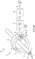
- FIG. 6A is a schematic diagram of the differential current electromagnetic sensor shown in FIG. 5 .
- FIG. 6B is an enlarged perspective view showing the differential current electromagnetic sensor shown in FIG. 6A .
- Shown in FIGS. 6A - 6B are power cable 14, first power lead 16, second power lead 18, leakage current measurement system 48, differential current detector 50, toroid core 52, toroid center region 54, gap faces 56A, 56B, magnetic gap 58, magnetic flux sensing device 60, bias voltage connections 62A, 62B, sensor output connections 64A, 64B, sensing device cable 76, interface circuit 78, leakage current signal 80, processor 82, and prognostic data output 84.
- Also shown in FIGS. 6A - 6B is the magnetic flux ⁇ across magnetic gap 58.
- Power cable 14 provides an electrical connection between polarity selection circuit 44 and heater 20, as shown and described above in regard to FIG. 5 .
- First power lead 16 and second power lead 18 each include a central conductive core that is surrounded by an insulating material, together being held together by an outer cable sheath (not labeled) to form power cable 14.
- the insulating material on first and second power leads 16, 18, and the outer cable sheath are all nonmetallic in the region near differential current detector 50, thereby providing negligible electromagnetic shielding.
- the outer cable sheath on power cable 14 can be omitted.
- first power lead 16 and second power lead 18 can be twisted together, or they can be untwisted.
- Toroid core 52 defines toroid center region 54, thereby providing for the passage of wires, cables, and the like.
- Power cable 14 can be described as passing through toroid center region 54, as shown in FIG. 6A .
- Power cable 14 can also be described as traversing toroid center region 54.
- Toroid core 52 is a gapped iron core transformer.
- toroid core 52 is a ferrite core, made from a material that has a relatively high value of magnetic permeability, as may be commonly used in the electrical art as a transformer core.
- Toroid core 52 can also be referred to as a gapped circular transformer core.
- toroid core can be made from other materials that are capable of creating magnetic flux ⁇ across magnetic gap 58.
- Magnetic flux sensing device 60 is positioned in magnetic gap 58, whereby magnetic flux ⁇ passes through magnetic flux sensing device 60.
- Components that hold toroid core 52 in place, and that hold magnetic flux sensing device 60 in position in magnetic gap 58 are not shown in FIGS. 6A - 6B but will be shown and described later in FIGS. 8A - 8B and 9A - 9B .
- magnetic flux sensing device 60 detects a value of magnetic flux ⁇ that is related to the difference between inlet current l in and outlet current l out .
- leakage current l L is non-zero as a result of the properties of heater 20, as described above in regard to FIG. 5 and as shown in Equation 2, the resulting magnetic flux ⁇ passing through magnetic flux sensing device 60 is representative of the value of leakage current l L .
- magnetic field B and associated magnetic flux ⁇ will be alternating (i.e., time-varying).
- Magnetic gap 58 can also be referred to as an air gap.
- magnetic flux sensing device 60 is a Hall effect sensor that produces an output voltage representative of the value of magnetic flux ⁇ passing therethrough (i.e., magnetic flux ⁇ across magnetic gap 58).
- Interface circuit 78 provides a bias voltage to bias voltage connections 62A, 62B on magnetic flux sensing device 60, and interface circuit 78 receives an output voltage (i.e., the "Hall effect voltage") across sensor output connections 64A, 64B.
- Bias voltage connections 62A, 62B and sensor output connections 64A, 64B are routed as insulated conductors through sensing device cable 76.
- the output voltage from magnetic flux sensing device 60 is representative of the value of leakage current l L associated with heater 20.
- heater control circuit 42 provides a DC voltage to heater 20, as in the illustrated embodiment, then the output voltage across sensor output connections 64A, 64B will typically be DC value.
- polarity selection circuit 44 can reverse the polarity of electrical power supplied to heater 20, as described above in regard to FIG. 5 . This polarity reversal will typically result in a reversal of the polarity of leakage current l L , and correspondingly, the direction of magnetic flux ⁇ passing through magnetic flux sensing device 60.
- interface circuit 78 is configured to adjust the value and/or polarity of bias voltage supplied to bias voltage connections 62A, 62B to accommodate the reversal of magnetic flux ⁇ .
- interface circuit 78 can receive a signal from polarity selection circuit 44 or from a system providing a polarity selection signal to polarity selection circuit 44 to accommodate a shift in the output voltage across sensor output connections 64A, 64B as a result of the magnetic flux ⁇ reversal.
- interface circuit 78 can be configured to provide a proper value of bias voltage supplied to bias voltage connections 62A, 62B, and/or to receive and process a corresponding time-varying output voltage across sensor output connections 64A, 64B to calculate the corresponding value of leakage current l L .
- the descriptions of interface circuit 78, leakage current signal 80, processor 82, and prognostic data output 84 are as provided above in regard to FIG. 5 .
- FIG. 7 is a schematic diagram of a second embodiment of differential current detector 50 shown in FIG. 5 . Shown in FIG. 7 are power cable 114, first power lead 116, second power lead 118, toroid core 152, toroid center region 154, magnetic gap 158, magnetic flux sensing device 160, and sensing device cable 176, all having descriptions substantially similar to those provided above in regard to FIGS. 6A - 6B .
- the illustrated embodiment shown in FIG. 7 can be beneficial in providing a greater sensitivity in measuring leakage current l L , thereby allowing smaller values of leakage current l L to be measured and processed by control system 40. This can improve the sensitivity of differential current detector 150 to smaller values of leakage current l L , and/or can improve the measurement resolution of differential current detector 150.
- first and second power leads 16, 18, 116, 118 can each have a wire size of 16 AWG (1.31 mm 2 cross-sectional area)
- power cable 14, 114 can have an outside diameter (not labeled) of about 0.25 inch (6.4 mm)
- toroid core 52, 152 can have an inside diameter (not labeled) of about 0.5 inch (12.7 mm). All sizes of power cable 14, 114 (including first and second power leads 16, 18, 116, 118) and toroid core 52, 152 are within the scope of the present disclosure.
- power cable 14, 114 can include more than two conductors (i.e., first and second power leads 16, 18, 116, 118).
- power cable 14, 114 can be sheathed (e.g., braided metallic sheath) in regions other than in the vicinity of toroid core 52, 152.
- toroid core 52, 152 can include a split (not shown in FIGS. 6A and 7 ) that can allow toroid core 52, 152 to be temporarily opened and/or separated into two halves to allow differential current detector 50, 150 to be installed on an existing power cable 14, 114, with various means being used to hold toroid core 52, 152 together.
- the resulting apparatus can be described as a clamp that can be placed around an existing power cable 14, 114.
- toroid core 52, 152 can be replaced with a magnetic core having a physical shape that is non-toroid (i.e., non-circular).
- toroid core 52, 152 can be referred to as a magnetic core.
- Non-limiting exemplary non-toroid shapes include oval, elliptical, hexagonal, pentagonal, square, and rectangular.
- magnetic cores having geometric shapes that involve more than a single opening can also be used, with non-limiting examples including E-cores and El-cores.
- An embodiment of an El-core will be shown later in FIG. 10 .
- Any non-toroid shape can include one or more flux-shaping features.
- An exemplary flux-shaping feature is rounded corners on a square magnetic core.
- FIG. 8A is a cross-sectional view showing a heater cable sensor clamp for a differential current electromagnetic sensor in a closed position.
- FIG. 8B is a cross-sectional view showing the heater cable sensor clamp shown in FIG. 8A in an open position. Shown in FIGS.
- Clamp fixture 200 includes base assembly 202 and upper assembly 204 which can rotate open and close about hinge 206.
- Base assembly cavity 208 accommodates locking device 210 which passes through upper assembly port 209.
- An exemplary locking device 210 is a threaded fastener that matably engages with threads on base assembly cavity 208.
- the descriptions of power cable 214, first power lead 216 and second power lead 218 are substantially similar to those provided above in regard to FIGS. 2A , 5 , and 7 .
- first and second power leads 216, 218 include stranded conductors that are surrounded by a sheath (not labeled), while including additional fill material (not labeled) within the outer sheath (not labeled) of power cable 214.
- first and/or second power leads 216, 218 can be a solid conductor.
- power cable can exclude the fill material, the sheath, or both.
- power cable 214 can include additional wires and/or components.
- differential current detector 250 includes a split toroid core having toroid core upper portion 252A and toroid core base portion 252B, which together define toroid center region 254 (when closed) and toroid center region 254' (when not in a closed position).
- the magnetic gap i.e., air gap
- Toroid core split 270 is defined by upper portion face 270A and base portion face 270B.
- clamp fixture 200 When clamp fixture 200 is in an open position (i.e., as shown in FIG. 8B ), the separation between upper portion face 270A and base portion face 270B (not labeled) is sufficient to accommodate the insertion of removal of power cable 214, thereby accommodating the placement of clamp fixture 200 on an existing power cable 214. This can be beneficial in facilitating the installation and/or removal of clamp fixture 200 on an existing power cable 214 (i.e., when heater 20 and associated wiring is in place on aircraft 10 prior to utilizing clamp fixture 200).
- upper portion face 270A makes physical contact with base portion face 270B, thereby maximizing the transfer of magnetic flux ⁇ across toroid split 270.
- a magnetic gap may exist between upper portion face 270A and base portion face 270B.
- the magnetic gap between upper portion face 270A and base portion face 270B could be referred to as a second magnetic gap (i.e., second air gap), and the magnetic gap between gap faces 256A, 256B could be referred to as a first magnetic gap (i.e., first air gap).
- FIG. 9A is a perspective view of a second embodiment a heater cable sensor clamp in a closed position.
- FIG. 9B is a perspective view of the heater cable sensor clamp shown in FIG. 9A in an open position. Shown in FIGS. 9A - 9B are clamp fixture 300, base assembly 302, upper assembly 304, locking device 310, power cable 314, toroid core upper portion 352A, toroid core base portion 352B, toroid center region 354', magnetic flux sensing device 360, and sensing device cable 376.
- clamp fixture 300 The descriptions of clamp fixture 300, base assembly 302, upper assembly 304, locking device 310, power cable 314, toroid core upper portion 352A, toroid core base portion 352B, toroid center region 354', and magnetic flux sensing device 360 are similar to those provided above in regard to FIGS. 8A - 8B . Some of the features shown in FIGS. 8A - 8B are not labeled in FIGS. 9A - 9B for ease of illustration.
- the description of sensing device cable 376 is similar to that provided above in regard to FIGS. 6A - 6B . In the illustrated embodiment, sensing device cable 376 provides an electrical connection between clamp fixture (i.e., magnetic flux sensing device 360) and an interface circuit (not shown in FIGS. 9A - 9B ).
- the interface circuit can be included in clamp fixture 300.
- a cable could provide electrical power to an interface circuit that is housed within clamp fixture 300, and the same cable, or a different cable, could transmit the leakage current signal from clamp fixture 300 to a processor.
- FIG. 10 is a side view of a third embodiment of differential current detector 50 shown in FIG. 5 .
- Shown in FIG. 10 are power cable 414, first power lead 416, second power lead 418, differential current detector 450, E-core 452, center member453, center regions 454A, 454B, l-core 455, magnetic gap 458, magnetic flux sensing device 460, and sensing device cable 476.
- Power cable 414, first power lead 416, second power lead 418, magnetic gap 458, magnetic flux sensing device 460, and sensing device cable 476 all have descriptions substantially similar to those provided above in regard to FIGS. 6A - 6B .
- E-core 452 and l-core 455 form an El-core defining center regions 454A and 454B, through each of which power cable 414 passes as shown.
- the difference between inlet current l in and outlet current l out i.e., leakage current I L
- the combined magnetic field in center member 453 is about 2B, being the sum of magnetic field B in each of the outer members, but this can be different because of flux leakage effects and the like.
- magnetic flux sensing device 460 senses magnetic flux ⁇ across magnetic gap 458 in a manner similar to that described above in regard to FIGS. 6A - 6B .
- an advantage of using an El-core for differential current detector 450 is the relative ease of separating and/or joining E-core 452 and l-core 455, which can be beneficial in installing differential current detector 450 on an existing power cable 414.
- the EI-core differential current detector 450 shown in FIG. 10 can be used in some embodiments to provide a compact design that provides greater leakage current l L sensing capability than the toroid design shown in FIG. 6A .
- leakage current l L sensing capability can be further enhanced by passing power cable 414 through center regions 454A and/or 454B more than once.
- power cable 414 can pass through center regions 454A, 454B three times, in a manner similar to that shown in FIG. 7 .
- An EI-core is a non-limiting example of many possible geometric shapes that can be used to form the magnetic core of differential current detector 50, 150, 450.
- magnetic flux sensing device 60 is a Hall effect sensor. All other magnetic flux sensing devices are within the scope of the present disclosure.
- magnetic flux sensing device 60 can be a magnetoresistive (MR) element.
- An MR element has an electrical resistance that varies in the presence of a magnetic flux ⁇ .
- interface circuit 78 can be configured to drive a sensing current through magnetic flux sensing device 60 (i.e., an MR element) while measuring a resulting voltage drop across the MR element as being an indication of magnetic flux ⁇ , and accordingly, of leakage current l L .
- MR sensors are within the scope of the present disclosure, with non-limiting examples including anisotropic magnetoresistance (AMR), tunnel-magnetoresistance (TMR), giant magnetoresistance (GMR) MR sensors. Moreover, all other types of magnetic flux sensors are within the scope of the present disclosure.
- AMR anisotropic magnetoresistance
- TMR tunnel-magnetoresistance
- GMR giant magnetoresistance
- the exemplary embodiments shown and described in the present disclosure pertain to heaters on aircraft air data probes.
- the scope of the present disclosure includes heaters on all aircraft components, with non-limiting examples including fixed and rotary wings and aircraft control surfaces.
- the scope of the present disclosure includes all electrical heaters that can be receive electrical power via two electrical leads (i.e., inlet current l in and outlet current l out ), without regard to power type (i.e., AC or DC), voltage, frequency, current, power, or location.
- Other exemplary power supply frequencies include 50 Hz and 60 Hz. Accordingly, leakage current detector 50, 150 can be used on one or more heaters 20 that are located or installed in any vehicle, building, or other location.
- Non-limiting examples of types of heaters that are within the scope of the present disclosure include wing ice protection heaters, water heaters, tank heaters, process heaters, stoves, ovens, and floor heaters that can be installed on aircraft, non-aircraft vehicles, buildings (e.g., residential, commercial, industrial, military), factories, and so on.
- a further embodiment of the foregoing system further comprising an interface circuit configured to: provide electrical power to the magnetic flux sensing device; receive the magnetic flux signal from the magnetic flux sensing device, the magnetic flux signal indicative of the magnetic flux across the air gap; and produce an output signal that is representative of the magnetic flux across the air gap.
- the magnetic flux sensing device is a Hall effect sensor
- the interface circuit provides a bias voltage to the Hall effect sensor
- the output signal is a voltage representative of the magnetic flux across the air gap.
- the heater power supply provides an alternating current to the heater;
- the magnetic flux across the air gap is an alternating magnetic flux;
- the interface circuit is configured to receive an alternating magnetic flux signal from the magnetic flux sensing device.
- the magnetic flux sensing device is a magnetoresistive sensor
- the output signal is a resistance value representative of the magnetic flux across the air gap.
- the heater comprises: a resistive heating element; electrical insulation surrounding the resistive heating element; and a metallic sheath surrounding the electrical insulation; wherein: the first current flows into the resistive heating element to provide heat; the second current flows out of the resistive heating element; the leakage current flows from the resistive heating element to the metallic sheath; and the first current is equal to the sum of the second current and the leakage current.
- magnetic core is a toroidal core, a square core, or an El-core.
- a further embodiment of the foregoing system further comprising a polarity selection circuit configured to applying to the heater either a first polarity heater voltage or a second polarity heater voltage.
- a further embodiment of the foregoing system further comprising a clamp fixture, wherein: the magnetic core further includes a split, thereby defining a first core piece and a second core piece; and the clamp fixture comprises: a first clamp piece, the first core piece and the magnetic flux sensing device disposed on the first clamp piece; a second clamp piece, the second core piece disposed on the second clamp piece; and a hinge assembly, configured to align the first clamp piece with the second clamp piece, wherein the magnetic core forms a magnetic circuit when the clamp fixture is in a closed position.
- clamp fixture further comprises a locking mechanism, the locking mechanism configured to hold the clamp fixture in the closed position.
- the heater is disposed on an aircraft component; and the aircraft component disposed on an external portion of an aircraft.
- the heater is disposed on an aircraft component; the aircraft component disposed on an external portion of an aircraft; and the heater is configured to control ice formation on the aircraft component.
- a method of monitoring a leakage current in a heater connected to a power supply by a power cable comprising a first power lead conducting an inlet current defining an inlet current direction and a second power lead conducting an outlet current defining an outlet current direction, the outlet current direction being opposite to the inlet current direction, the power cable traversing a center region of a magnetic core, the magnetic core including an air gap that is configured to accommodate a magnetic flux sensing device positioned therein, the magnetic flux sensing device configured to provide a magnetic flux signal that is representative of a magnetic flux across the air gap, the magnetic flux indicative of a difference between the inlet current and the outlet current, the method comprising: supplying electrical power from a power source to a heater via the power cable, wherein: the inlet current flows through the first power lead; and the outlet current flows through the second power lead; providing electrical power to the magnetic flux sensing device; receiving the magnetic flux signal from the magnetic flux sensing device, the magnetic flux signal indicative of the magnetic flux across the air gap; and producing an output signal that is representative
- the method of the preceding paragraph can optionally include, additionally and/or alternatively, any one or more of the following features, configurations and/or additional components:
- a further embodiment of the foregoing method wherein: the power source provides direct current to the heater; the magnetic flux sensing device is a Hall effect sensor; providing electrical power to the magnetic flux sensing device comprises providing a bias voltage to the Hall effect sensor; and the output signal is a voltage representative of the magnetic flux across the air gap.
- the power cable passes through the center region once;
- the magnetic core further includes a split, thereby defining a first core piece and a second core piece;
- the clamp fixture comprises: a first clamp piece, the first core piece and the magnetic flux sensing device disposed on the first clamp piece; a second clamp piece, the second core piece disposed on the second clamp piece; and a hinge assembly, configured to align the first clamp piece with the second clamp piece, wherein the magnetic core forms a magnetic circuit when the clamp fixture is in a closed position.
- the magnetic core is a toroidal core, a square core, or an El-core.
Landscapes
- Physics & Mathematics (AREA)
- General Physics & Mathematics (AREA)
- Engineering & Computer Science (AREA)
- Radar, Positioning & Navigation (AREA)
- Remote Sensing (AREA)
- Aviation & Aerospace Engineering (AREA)
- Testing Of Short-Circuits, Discontinuities, Leakage, Or Incorrect Line Connections (AREA)
Abstract
Description
- This application is related to
U.S. Patent Application No. 16/425695 - The present disclosure relates generally to probes, and in particular, to a system and method of measuring electrical leakage current in air data probe heaters.
- Probes are utilized to determine characteristics of an environment. In aircraft systems, for example, air data probes may be implemented on the external portions of the aircraft to aid in determination of conditions such as airspeed, altitude, and angle of attack, among others. Air data probes are prone to ice accretion during flight, which can affect their performance. Accordingly, electrical heaters are integrated into modern air data probes for helping control ice build-up.
- Being exposed to harsh environmental conditions and temperature extremes, the electric heaters in air data probes are prone to degradation over time, possibly leading to their ultimate failure. When an air data probe heater fails, the performance of the air data probe can be affected. Moreover, a failed air data probe can ground a flight, thereby impacting flight scheduling and flight operations cost. It is desirable to be able to measure electrical leakage current during operation of air data probe heaters to help predict when an air data probe heater will require replacement, thereby mitigating the aforementioned impact on an aircraft's operation.
- A system for monitoring leakage current in a heater connected to a heater power supply by a power cable. The power cable has a first power lead conducting an inlet current defining an inlet current direction and a second power lead conducting an outlet current defining an outlet current direction that is opposite the inlet current direction. The system includes a differential current electromagnetic sensor having a magnetic core defining a center region that the power cable is configured to pass through one or more times. The magnetic core includes an air gap, and a magnetic flux sensing device positioned in the air gap. The magnetic flux sensing device is configured to provide a magnetic flux signal that is representative of a magnetic flux across the air gap, whereby the magnetic flux across the air gap is indicative of a difference between the inlet current and the outlet current, and the difference between the inlet current and the outlet current defines the leakage current.
- A method for monitoring leakage current in a heater connected to a heater power supply by a power cable. The power cable has a first power lead conducting an inlet current defining an inlet current direction and a second power lead conducting an outlet current defining an outlet current direction that is opposite the inlet current direction. The power cable traverses a center region of a magnetic core that has an air gap that is configured to accommodate a magnetic flux sensing device positioned therein. The magnetic flux sensing device is configured to provide a magnetic flux signal that is representative of a magnetic flux across the air gap, whereby the magnetic flux is indicative of a difference between the inlet current and the outlet current. The method includes supplying electrical power from a power source to a heater via the power cable whereby the inlet current flows through the first power lead and the outlet current flows through the second power lead, providing electrical power to the magnetic flux sensing device, receiving the magnetic flux signal from the magnetic flux sensing device whereby the magnetic flux signal is indicative of the magnetic flux across the air gap, and producing an output signal that is representative of the magnetic flux across the air gap. The difference between the inlet current and the outlet current defines a leakage current.
-
-
FIG. 1 is a schematic diagram illustrating an aircraft that includes a plurality of air data probes. -
FIG. 2A is a schematic diagram of an air data probe heater circuit. -
FIG. 2B is a cross-sectional view of the air data probe heater taken alongline 2B - 2B ofFIG. 2A . -
FIG. 3 is a partial cross-sectional view illustrating the air data probe heater with compromised insulation taken along line 3 - 3 ofFIG. 2B . -
FIG. 4 is a partial cross-sectional view illustrating the air data probe heater with a compromised resistive heating element taken along line 4 - 4 ofFIG. 2B . -
FIG. 5 is a schematic diagram of a heater monitoring circuit. -
FIG. 6A is a schematic diagram of the differential current electromagnetic sensor shown inFIG. 5 . -
FIG. 6B is an enlarged perspective view showing the differential current magnetic flux sensor shown inFIG. 6A . -
FIG. 7 is a schematic diagram of a second embodiment of the differential current electromagnetic sensor shown inFIG. 5 . -
FIG. 8A is a cross-sectional view showing a heater cable sensor clamp for a differential current electromagnetic sensor in a closed position. -
FIG. 8B is a cross-sectional view showing the heater cable sensor clamp shown inFIG. 8A in an open position. -
FIG. 9A is a perspective view of a second embodiment a heater cable sensor clamp in a closed position. -
FIG. 9B is a perspective view of the heater cable sensor clamp shown inFIG. 9A in an open position. -
FIG. 10 is a side view of a third embodiment of the differential current electromagnetic sensor shown inFIG. 5 . -
FIG. 1 is a schematicdiagram illustrating aircraft 10 that includes a plurality ofair data probes 12a - 12n.Air data probes 12a - 12n can be any type of probe with non-limiting examples including pitot probes, pitot-static probes, total air temperature (TAT) probes, or angle-of-attack (AOA) sensors. Any number n of air data probes can be included on a particular aircraft, with eachair data probe 12a - 12n typically including an integrated heater to control icing. As used in the present disclosure, one of anyair data probes 12a - 12n can be referred to as air data probe 12. The exemplary embodiment shown inFIG. 1 is a commercial fixed-wing aircraft. Air data probe 12 can be used on other vehicles, with non-limiting examples including military aircraft, rotary wing aircraft, unmanned aerial vehicles, spacecraft, and ground vehicles. -
FIG. 2A is a schematic diagram of an air data probe heater circuit. Shown inFIG. 2A are aircraft power supply 13,power cable 14,first power lead 16,second power lead 18, andheater 20. Also labeled inFIG. 2A are inlet current lin, outlet current lout, and length L (i.e., heater length). Aircraft power supply 13 provides electrical power viapower cable 14. In an exemplary embodiment, aircraft power supply 13 provides direct current at 28 VDC. In some embodiments, aircraft power supply 13 can provide a voltage different from this. In other embodiments, aircraft power supply 13 can provide an alternating current (AC) voltage. An exemplary AC frequency that can be provided by aircraft power supply 13 include is 400 Hz.First power lead 16 andsecond power lead 18 together provides an electrical connection toheater 20, thereby allowing electrical current to flow throughheater 20.Heater 20 can be referred to as an air data probe heater. In a typical embodiment,heater 20 can consume 200 - 300 Watts in converting electrical power into thermal power. In some embodiments,heater 20 can draw an electrical power level that is different form this.Heater 20 is typically integrated into air data probe 12, and is energized (i.e., powered) to reduce or prevent ice formation on the respective air data probe by raising the surface temperature of the air data probe to a value that can melt and/or control the formation of ice on air data probe 12. Inlet current lin flows intoheater 20 throughfirst power lead 16, and outlet current lout flows fromheater 20 throughsecond power lead 18, as shown inFIG. 2A . The directions of current flow lin, lout are illustrative, using a convention that is used in the electrical art. Under ideal circumstances, lin and lout are approximately equivalent, meaning that there is no other path for current to flow fromheater 20. However,heater 20 is prone to failure, as will be described in detail later inFIGS. 3 - 4 . A failure ofheater 20 will generally occur at a point along the length L ofheater 20, with a failure ofheater 20 typically requiring a replacement of the associated air data probe. It is to be appreciated that the illustrated embodiment is greatly simplified, and associated control circuitry, circuit breakers, and the like are not shown.Heater 20 is depicted as a straight element for ease of illustration but can have other physical configurations in various embodiments. The values provided for power supply voltage and frequency, and heater power consumption, are exemplary and can be different in variousembodiments. Power cable 14,first power lead 16,second power lead 18, andheater 20 can be referred to as a heating arrangement. -
FIG. 2B is a cross-sectional view of an air data probe heater taken alongline 2B - 2B ofFIG. 2A . Shown inFIG. 2B areheater 20,resistive heating element 22,insulation 24, andsheath 26. In the illustrated embodiment,resistive heating element 22 is made of an oxidation-resistant alloy.Insulation 24 surroundsresistive heating element 22.Insulation 24 is an electrically insulating material that provides heat conduction outward fromresistive heating element 22.Sheath 26 is an oxidation-resistant metallic material that surroundsinsulation 24, thereby containinginsulation 24 while providing thermal conductivity fromheater 20 to the air data probe in whichheater 20 is installed.Sheath 26 can be referred to as a metallic sheath. It is to be appreciated that the various materials are selected to provide various desirable properties (e.g., strength, thermal conductivity, oxidation resistance), while also optimizing service life. Notwithstanding,heater 20 is prone to failure over time, as will be described in more detail inFIGS. 3 - 4 . -
FIG. 3 is a partial cross-sectionalview illustrating heater 20 with compromisedinsulation 24 taken along line 3 - 3 ofFIG. 2B. FIG. 4 is a partial cross-sectionalview illustrating heater 20 with a compromisedresistive heating element 22 taken along line 4 - 4 ofFIG. 2B. FIGS. 3 - 4 illustrate an exemplary mode of failure ofheater 20, as will be described, while other failure mechanisms forheater 20 can also occur in various embodiments. Shown inFIGS. 3 - 4 areheater 20,resistive heating element 22,insulation 24,sheath 26, andheater faults sheath 26 is compromised, contaminants can leak throughsheath 26 toinsulation 24, causing the material ofinsulation 24 to oxidize, change properties, and/or otherwise break down, thereby causing a path for leakage current lL to flow fromresistive heating element 22 tosheath 26. Non-limiting examples of contaminants include oxygen, moisture, dust, carbon, fuel, oil, deicing fluid, and combustion products. Non-limiting examples of events that can compromisesheath 26 include external damage, latent defects, and fatigue failure (e.g., from vibration).Heater fault 32, shown inFIG. 3 , depictsexemplary heater fault 32 that can result from the aforementioned failure mechanism. Leakage current lL flows throughheater fault 32 fromresistive heating element 22 tosheath 26, as shown. Over time,heater fault 32 can grow in magnitude, becomingheater fault 32A as shown inFIG. 4 . An increase in the value of leakage current lL typically accompanies the progression ofheater fault 32 over the life ofheater 20. Moreover, the value of leakage current lL flowing throughheater fault 32 affect the rate of deterioration ofheater fault 32, with higher values of leakage current lL generally resulting in a greater rate of deterioration. Accordingly, if the value of leakage current lL for aparticular heater fault 32 can be reduced, the rate of deterioration can be correspondingly reduced, thereby prolonging the useful life ofheater 20. In some embodiments, reversing the electrical polarity of power supplied toheater 20 can reduce the rate of deterioration ofheater fault 32, which can extend the life ofheater 20. -
FIG. 5 is a schematic diagram of a heater monitoring circuit. Shown inFIG. 5 arepower cable 14,first power lead 16,second power lead 18,heater 20,resistive heating element 22,insulation 24,sheath 26, leakagecurrent path 30,control system 40,heater control circuit 42,polarity selection circuit 44, leakagecurrent measurement system 48, leakagecurrent detector 50,interface circuit 78, leakagecurrent signal 80,processor 82, andprognostic data output 84. Also labeled inFIG. 5 are inlet current lin, outlet current lout, leakage current lL, and lengthL. Power cable 14 is depicted schematically, representing an unspecified length of a two-or-more conductor cable that includesfirst power lead 16 andsecond power lead 18. The descriptions of aircraft power supply 13,power cable 14,first power lead 16,second power lead 18, andheater 20,resistive heating element 22,insulation 24, andsheath 26 are substantially as provided above in regard toFIGS. 2A - 2B .Control system 40 provides monitoring ofheater 20, as will be described. Accordingly,control system 40 can also be referred to as a heater monitoring circuit.Heater control circuit 42 receives a heater control signal (not shown) from an aircraft data system (not shown), thereby controlling the flow of electrical power from power supply 13 toheater 20 to control the accretion of ice on air data probe 12, as described above in regard toFIG. 2A . In an exemplary embodiment, the heater control signal can be generated in part based on the air temperature, aircraft airspeed, and liquid water content (LWC) that is measured by other systems (not shown) onaircraft 10, andheater control circuit 42 cycles electrical power on and off (i.e., power duty cycle control) toheater 20.Polarity selection circuit 44 controls the polarity of electrical power supplied toheater 20. In the illustrated embodiment, electrical polarity can be either "forward" or "reverse" polarity. The forward polarity can also be referred to as the normal polarity (i.e., as would exist in the absence of polarity selection circuit 44).Polarity selection circuit 44 can receive a polarity selection signal directing either the "forward" or "reverse" electrical polarity of power supplied toheater 20. The forward polarity can be referred to as a first polarity, and the reverse polarity can be referred to as a second polarity. In the illustrated embodiment,polarity selection circuit 44 is represented visually as a mechanical polarity-reversing circuit using a double-pole/double-throw (DPDT) electrical switch. In some embodiments,polarity selection circuit 44 can use electronic components (e.g., semiconductor devices) to reverse the electrical polarity. In some embodiments,polarity selection circuit 44 can be omitted fromcontrol system 40, such thatheater 20 receives a fixed polarity of electrical power from heater control circuit 42 (i.e., as supplied from aircraft power supply 13). In some of these other embodiments, the electrical polarity of power supplied toheater 20 can be manually reversed, for example, by switching power leads during a maintenance operation whileaircraft 10 is not operating. - When
heater 20 is operating normally, inlet current lin flows into resistive heating element 22 (i.e., heater 20) throughfirst power lead 16, and outlet current lout flows fromresistive heating element 22 throughsecond power lead 18, with lin being approximately equal to lout as described above in regard toFIG. 2A . A typical value of heater current flow (i.e., lin, lout) can range from about 1 - 3 amps (A), however these values can be different in other embodiments. A small amount of leakage current lL flows through leakagecurrent path 30, schematically represented as flowing fromsheath 26 to ground (i.e., chassis ground).The relationship between inlet current lin, outlet current lout, and leakage current lL can be calculated using Equation 1 as follows:
heater 20 will experience a nominal value of leakage current lL by virtue of the nature ofinsulation 24. When a newly-manufactured heater 20 (i.e., associated air data probe 12) is installed, the baseline value of leakage current lL is typically measured and recorded for each power supply polarity (i.e., forward and reverse). These values can be referred to as the baseline leakage current lL-baseline, or as the leakage current lL at inception. A typical value of baseline leakage current lL-baseline can range from about 10 - 50 microamps (µA), but this value can vary over a wide range depending on the particular embodiment ofheater 20. For example, in some embodiments, baseline leakage current lL-baseline can range up to about 2 milliamps (mA), or higher. In other embodiments, baseline leakage current lL-baseline can be less than 10 µA. Asheater 20 operates, it is normal for leakage current lL to gradually increase as a result of minor degradation ofinsulation 24. The normal migration of environmental impurities (e.g., contaminants as discussed above in regard toFIGS. 3 - 4 ) intoinsulation 24 is an example of a typical degradation ofinsulation 24 over the lifetime of aparticular heater 20. Becauseheater 20 is typically powered when an aircraft is flying, an expected heater lifetime can be expressed as a measure of flight hours. Several factors (e.g., physical size ofheater 20, power consumption ofheater 20, physical location of heater 20) can affect the expected lifetime ofheater 20 in a particular embodiment, with typical values ranging from about 13K - 100K flight hours. In some embodiments, the expected lifetime ofheater 20 can exceed 100K hours. - Heater end-of-life (EOL) is typically associated with a particular threshold value lL-threshold, which can vary depending on the particular embodiment of
heater 20. Exemplary values of threshold value lL-threshold can range from about 2 - 50 mA, but this can vary in different embodiments. Accordingly, the remaining useful life (RUL) can be estimated from measured values of leakage current lL under each of the forward and reverse polarities. An object of the present disclosure is to provide a system and method of measuring the value of leakage current lL throughout the service life ofheater 20 for each of the forward and reverse polarities of power supplied toheater 20, thereby providing an indication of RUL while also identifying an abnormal condition that could be indicative of a premature failure ofheater 20. It is desirable to replace an air data probe (i.e., and associated heater 20) prior to the EOL or prior to the point of failure, to avoid an operational delay and interruption (ODI) that could result following a failure. On the other hand, because replacing air data probe 12 (i.e., and associated heater 20) can be expensive in terms of time and cost, while also removing associatedaircraft 10 from operation, it is desirable to extract a maximum useful service life fromheater 20 prior to the point of replacement. - Referring to
FIG. 5 and Equation 1, the value of leakage current lL can be expressed inEquation 2 as being the difference between inlet current lin and outlet current lout:
current detector 50 is a differential current electromagnetic sensor. Leakagecurrent measurement system 48 includes leakagecurrent detector 50 andinterface circuit 78, the operation of which will be described in greater detail inFIGS. 6A - 6B . Leakagecurrent measurement system 48 measures the value of leakage current lL inheater 20 under the particular polarity (i.e., forward or reverse), providing leakagecurrent signal 80 toprocessor 82. In the illustrated embodiment, leakagecurrent signal 80 is a digital signal that represents the measured value of leakage current lL.Processor 82 calculates the value of value of leakage current lL based on leakagecurrent signal 80.Processor 82 can also monitor and record the leakage current lL that is measured by leakagecurrent measurement system 48 at the particular heater power polarity (i.e., forward or reverse) for each operating period (e.g., flight) ofheater 20. In an exemplary embodiment,processor 82 can generate the polarity control signal that is provided topolarity selection circuit 44, as described above. In some embodiments,processor 82 can controlpolarity selection circuit 44 to optimize the lifetime ofheater 20. Therefore,processor 82 can monitor the health ofheater 20, while controlling the polarity of electrical power provided toheater 20, thereby extending the life ofheater 20.Processor 82 can be referred to as a prognostic processor. Accordingly,processor 82 providesprognostic data output 84 which can be received by various consumers onboardaircraft 10 and/or external toaircraft 10. The remaining useful life (RUL) ofheater 20 can be included inprognostic data output 84. In the illustrated embodiment,processor 82 is a digital processor that receives, stores, scales, and processes leakage current signal 80 (i.e., the digitized value of leakage current lL) that is received throughout the lifecycle ofheater 20, while associating leakagecurrent signal 80 with the polarity of electrical power supplied toheater 20, flight hours, and so on. Therefore,processor 82 includes internal and/or connected memory and/or storage devices.Processor 82 can receive and process the digitized leakage current value continuously or periodically. In the illustrated embodiment,processor 82 can include one or more processors (not shown inFIG. 5 ) that are configured to implement functionality and/or process instructions for execution withinprocessor 82. The one or more processors can be capable of processing instructions stored in one or more storage device(s) (not shown inFIG. 5 ). Examples of processors can include any one or more of: a microprocessor, a microcontroller, a digital signal processor (DSP), an application specific integrated circuit (ASIC), a field-programmable gate array (FPGA), or other equivalent discrete or integrated logic circuitry. In some embodiments,processor 82 can receive multiple inputs corresponding to multiple leakage current signals 80 from multiple associatedheaters 20. In other embodiments,processor 82 can receive data from other aircraft data sources and/or perform other functions in addition to those described here. In any of these embodiments,processor 82 can be a neural network. In some embodiments,processor 82 can provide information regarding one ormore heaters 20 with regard to the present and/or most recent values of leakage current lL for the forward and reverse polarities, the history of leakage current lL over time for each polarity (e.g., operating time, calendar time), the service life of heater 20 (e.g., operating time), the expected EOL, the calculated RUL, and status as to whetherheater 20 is restricted in operation to a particular polarity. Collectively, these various data can be referred to as prognostic data. The aforementioned data can be provided to other systems (e.g., avionics system) for use by crew members. In these or other embodiments, prognostic data output 84 (i.e., prognostic data) can be transmitted and/or downloaded to engineering teams at an airline's operator, maintenance facility, and/or the various component suppliers whereby the data can be reviewed, analyzed, and/or archived. When installed on a system that includes one ormore heaters 20,control system 40 can track the health of each ofmultiple heaters 20 aboardaircraft 10, allowing maintenance personnel to predict when failure ofheaters 20 are likely to occur so that maintenance can be scheduled prior to the point of expected failure for anyparticular heater 20. This can avoid flight delays that could ground an aircraft for emergent maintenance requirements, and it can also help prevent the in-flight failure of aparticular heater 20 which could be disruptive to the performance of an associated air data probe 12. -
FIG. 6A is a schematic diagram of the differential current electromagnetic sensor shown inFIG. 5 .FIG. 6B is an enlarged perspective view showing the differential current electromagnetic sensor shown inFIG. 6A . Shown inFIGS. 6A - 6B arepower cable 14,first power lead 16,second power lead 18, leakagecurrent measurement system 48, differentialcurrent detector 50,toroid core 52, toroid center region 54, gap faces 56A, 56B, magnetic gap 58, magneticflux sensing device 60,bias voltage connections sensor output connections sensing device cable 76,interface circuit 78, leakagecurrent signal 80,processor 82, andprognostic data output 84. Also shown inFIGS. 6A - 6B is the magnetic flux Φ across magnetic gap 58.Power cable 14 provides an electrical connection betweenpolarity selection circuit 44 andheater 20, as shown and described above in regard toFIG. 5 .First power lead 16 andsecond power lead 18 each include a central conductive core that is surrounded by an insulating material, together being held together by an outer cable sheath (not labeled) to formpower cable 14. The insulating material on first and second power leads 16, 18, and the outer cable sheath, are all nonmetallic in the region near differentialcurrent detector 50, thereby providing negligible electromagnetic shielding. In some embodiments, the outer cable sheath onpower cable 14 can be omitted. In these or other embodiments,first power lead 16 andsecond power lead 18 can be twisted together, or they can be untwisted.Toroid core 52 defines toroid center region 54, thereby providing for the passage of wires, cables, and the like.Power cable 14 can be described as passing through toroid center region 54, as shown inFIG. 6A .Power cable 14 can also be described as traversing toroid center region 54.Toroid core 52 is a gapped iron core transformer. In an exemplary embodiment,toroid core 52 is a ferrite core, made from a material that has a relatively high value of magnetic permeability, as may be commonly used in the electrical art as a transformer core.Toroid core 52 can also be referred to as a gapped circular transformer core. In some embodiments, toroid core can be made from other materials that are capable of creating magnetic flux Φ across magnetic gap 58. Magneticflux sensing device 60 is positioned in magnetic gap 58, whereby magnetic flux Φ passes through magneticflux sensing device 60. Components that holdtoroid core 52 in place, and that hold magneticflux sensing device 60 in position in magnetic gap 58 are not shown inFIGS. 6A - 6B but will be shown and described later inFIGS. 8A - 8B and9A - 9B . - It is known in the electrical art that an electrical current flowing in a conductor passing through a ferrite core induces a magnetic field B, thereby creating a magnetic flux Φ through magnetic gap 58. The magnetic field B can also be annotated with a vector symbol, as shown in
FIG. 6A . If the electrical current is a direct current (DC), as in the illustrated embodiment, then magnetic field B and associated magnetic flux Φ will be relatively constant for a particular condition ofheater 20. As electrical power is delivered toheater 20 by power cable 14 (e.g., as shown inFIG. 5 ), inlet current lin flows throughpower cable 14 in a direction that is opposite to that of outlet current lout, with both inlet current lin and outlet current lout flowing through toroid center region 54. Accordingly, the component of magnetic field B associated with inlet current lin is opposite in direction to the component of magnetic field B associated with outlet current lin, thereby providing a canceling effect. The net magnetic field B and magnetic flux Φ across magnetic gap 58 is a result of the difference between inlet current lin and outlet current lout. Accordingly, magneticflux sensing device 60 detects a value of magnetic flux Φ that is related to the difference between inlet current lin and outlet current lout. If inlet current lin were equal to outlet current lout (i.e., lin = lout), then the resulting magnetic flux Φ would be zero because the respective components of magnetic fields B from inlet current lin and outlet current lout are equal in magnitude but opposite in direction. Because leakage current lL is non-zero as a result of the properties ofheater 20, as described above in regard toFIG. 5 and as shown inEquation 2, the resulting magnetic flux Φ passing through magneticflux sensing device 60 is representative of the value of leakage current lL. In embodiments whereheater control circuit 42 provides an AC voltage toheater 20, then magnetic field B and associated magnetic flux Φ will be alternating (i.e., time-varying). Magnetic gap 58 can also be referred to as an air gap. - In the illustrated embodiment, magnetic
flux sensing device 60 is a Hall effect sensor that produces an output voltage representative of the value of magnetic flux Φ passing therethrough (i.e., magnetic flux Φ across magnetic gap 58).Interface circuit 78 provides a bias voltage to biasvoltage connections flux sensing device 60, andinterface circuit 78 receives an output voltage (i.e., the "Hall effect voltage") acrosssensor output connections Bias voltage connections sensor output connections sensing device cable 76. The output voltage from magneticflux sensing device 60 is representative of the value of leakage current lL associated withheater 20. Ifheater control circuit 42 provides a DC voltage toheater 20, as in the illustrated embodiment, then the output voltage acrosssensor output connections heater 20,polarity selection circuit 44 can reverse the polarity of electrical power supplied toheater 20, as described above in regard toFIG. 5 . This polarity reversal will typically result in a reversal of the polarity of leakage current lL, and correspondingly, the direction of magnetic flux Φ passing through magneticflux sensing device 60. Accordingly, ininterface circuit 78 is configured to adjust the value and/or polarity of bias voltage supplied tobias voltage connections interface circuit 78 can receive a signal frompolarity selection circuit 44 or from a system providing a polarity selection signal topolarity selection circuit 44 to accommodate a shift in the output voltage acrosssensor output connections heater 20, an alternating magnetic flux Φ will exist across magnetic gap 58 as described above. In these embodiments,interface circuit 78 can be configured to provide a proper value of bias voltage supplied tobias voltage connections sensor output connections interface circuit 78, leakagecurrent signal 80,processor 82, andprognostic data output 84 are as provided above in regard toFIG. 5 . -
FIG. 7 is a schematic diagram of a second embodiment of differentialcurrent detector 50 shown inFIG. 5 . Shown inFIG. 7 arepower cable 114,first power lead 116,second power lead 118,toroid core 152,toroid center region 154,magnetic gap 158, magneticflux sensing device 160, andsensing device cable 176, all having descriptions substantially similar to those provided above in regard toFIGS. 6A - 6B . In the illustrated embodiment,power cable 114 passes throughtoroid center region 154 three times (i.e., N = 3). The number of turns N can be said to be three, and the resulting magnetic field B for a particular value of leakage current lL will be approximately three times the value of that produced by a single pass through toroid center region 154 (e.g., as shown inFIG. 6A ). Accordingly, the value of magnetic flux Φ will be about three times as great across magnetic gap 158 (i.e., air gap) for a given value of leakage current lL as compared to that for a single turn (i.e., N = 1). The illustrated embodiment shown inFIG. 7 can be beneficial in providing a greater sensitivity in measuring leakage current lL, thereby allowing smaller values of leakage current lL to be measured and processed bycontrol system 40. This can improve the sensitivity of differentialcurrent detector 150 to smaller values of leakage current lL, and/or can improve the measurement resolution of differentialcurrent detector 150. - The embodiment shown in
FIG. 7 is exemplary, and in various embodiments practically any number of turns N can be used. For example, in some embodiments, differentialcurrent detector 150 can include two turns (N = 2). In other embodiments, differentialcurrent detector 150 can include four or more turns N. In some embodiments, the number of turns N can range from about 10 - 20. In other embodiments, the number of turns N can be greater than 20. Various factors can influence the number of turns N used in a particular embodiment, with non-limiting examples including the physical sizes ofpower cable 14, 114 (i.e., including first and second power leads 16, 18, 116, 118), and the physical size oftoroid core FIGS. 6A - 6B and 7 , first and second power leads 16, 18, 116, 118 can each have a wire size of 16 AWG (1.31 mm2 cross-sectional area),power cable toroid core power cable 14, 114 (including first and second power leads 16, 18, 116, 118) andtoroid core power cable power cable toroid core - In some embodiments,
toroid core FIGS. 6A and7 ) that can allowtoroid core current detector power cable toroid core power cable toroid core toroid core FIG. 10 . Any non-toroid shape can include one or more flux-shaping features. An exemplary flux-shaping feature is rounded corners on a square magnetic core. -
FIG. 8A is a cross-sectional view showing a heater cable sensor clamp for a differential current electromagnetic sensor in a closed position.FIG. 8B is a cross-sectional view showing the heater cable sensor clamp shown inFIG. 8A in an open position. Shown inFIGS. 8A - 8B areclamp fixture 200,base assembly 202,upper assembly 204, hinge 206,base assembly cavity 208,upper assembly port 209, lockingdevice 210,power cable 214,first power lead 216,second power lead 218,base assembly housing 240,upper assembly housing 242, differentialcurrent detector 250, toroid coreupper portion 252A, toroidcore base portion 252B,toroid center region 254, 254', gap faces 256A, 256B, magneticflux sensing device 260, toroid core split 270, upper portion face 270A, andbase portion face 270B.Clamp fixture 200 includesbase assembly 202 andupper assembly 204 which can rotate open and close abouthinge 206.Base assembly cavity 208 accommodates lockingdevice 210 which passes throughupper assembly port 209. Anexemplary locking device 210 is a threaded fastener that matably engages with threads onbase assembly cavity 208. The descriptions ofpower cable 214,first power lead 216 andsecond power lead 218 are substantially similar to those provided above in regard toFIGS. 2A ,5 , and7 . In the detail shown inFIGS. 8A - 8B , first and second power leads 216, 218 include stranded conductors that are surrounded by a sheath (not labeled), while including additional fill material (not labeled) within the outer sheath (not labeled) ofpower cable 214. In some embodiments, first and/or second power leads 216, 218 can be a solid conductor. In these or other embodiments, power cable can exclude the fill material, the sheath, or both. In some embodiments,power cable 214 can include additional wires and/or components. - Referring again to
FIGS. 8A - 8B , differentialcurrent detector 250 includes a split toroid core having toroid coreupper portion 252A and toroidcore base portion 252B, which together define toroid center region 254 (when closed) and toroid center region 254' (when not in a closed position). The magnetic gap (i.e., air gap) (not labeled inFIGS. 8A - 8B ) is defined by gap faces 256A, 256B when clamp fixture is in a closed position. The descriptions of the magnetic gap and of magneticflux sensing device 260 are substantially similar to that provided above in regard toFIGS. 6A - 6B . Toroid core split 270 is defined byupper portion face 270A andbase portion face 270B. Whenclamp fixture 200 is in an open position (i.e., as shown inFIG. 8B ), the separation betweenupper portion face 270A andbase portion face 270B (not labeled) is sufficient to accommodate the insertion of removal ofpower cable 214, thereby accommodating the placement ofclamp fixture 200 on an existingpower cable 214. This can be beneficial in facilitating the installation and/or removal ofclamp fixture 200 on an existing power cable 214 (i.e., whenheater 20 and associated wiring is in place onaircraft 10 prior to utilizing clamp fixture 200). Whenclamp fixture 200 is in a closed position (i.e., as shown inFIG. 8A ), upper portion face 270A makes physical contact withbase portion face 270B, thereby maximizing the transfer of magnetic flux Φ across toroid split 270. In some embodiments, whenclamp fixture 200 is in a closed position, a magnetic gap may exist betweenupper portion face 270A andbase portion face 270B. In these embodiments, the magnetic gap betweenupper portion face 270A andbase portion face 270B could be referred to as a second magnetic gap (i.e., second air gap), and the magnetic gap between gap faces 256A, 256B could be referred to as a first magnetic gap (i.e., first air gap). In some embodiments, it can be preferable to minimize the size of the second magnetic gap. It is to be appreciated that when upper portion face 270A makes physical contact withbase portion face 270B, the second magnetic gap is effectively eliminated from the magnetic circuit that includes toroid coreupper portion 252A and toroidcore base portion 252B. -
FIG. 9A is a perspective view of a second embodiment a heater cable sensor clamp in a closed position.FIG. 9B is a perspective view of the heater cable sensor clamp shown inFIG. 9A in an open position. Shown inFIGS. 9A - 9B areclamp fixture 300,base assembly 302,upper assembly 304, lockingdevice 310,power cable 314, toroid coreupper portion 352A, toroidcore base portion 352B, toroid center region 354', magneticflux sensing device 360, andsensing device cable 376. The descriptions ofclamp fixture 300,base assembly 302,upper assembly 304, lockingdevice 310,power cable 314, toroid coreupper portion 352A, toroidcore base portion 352B, toroid center region 354', and magneticflux sensing device 360 are similar to those provided above in regard toFIGS. 8A - 8B . Some of the features shown inFIGS. 8A - 8B are not labeled inFIGS. 9A - 9B for ease of illustration. The description ofsensing device cable 376 is similar to that provided above in regard toFIGS. 6A - 6B . In the illustrated embodiment,sensing device cable 376 provides an electrical connection between clamp fixture (i.e., magnetic flux sensing device 360) and an interface circuit (not shown inFIGS. 9A - 9B ). In some embodiments, the interface circuit, or portions of the interface circuit, can be included inclamp fixture 300. In an exemplary embodiment, a cable could provide electrical power to an interface circuit that is housed withinclamp fixture 300, and the same cable, or a different cable, could transmit the leakage current signal fromclamp fixture 300 to a processor. -
FIG. 10 is a side view of a third embodiment of differentialcurrent detector 50 shown inFIG. 5 . Shown inFIG. 10 arepower cable 414,first power lead 416,second power lead 418, differentialcurrent detector 450,E-core 452, center member453,center regions core 455, magnetic gap 458, magneticflux sensing device 460, andsensing device cable 476.Power cable 414,first power lead 416,second power lead 418, magnetic gap 458, magneticflux sensing device 460, andsensing device cable 476 all have descriptions substantially similar to those provided above in regard toFIGS. 6A - 6B . When mated together as shown inFIG. 10 , E-core 452 and l-core 455 form an El-core definingcenter regions power cable 414 passes as shown. In a manner similar to that described above in regard toFIGS. 6A - 6B , the difference between inlet current lin and outlet current lout (i.e., leakage current IL) creates magnetic field B in each of the outer members (not labeled) ofE-core 452, together being directed through l-core 455 as shown. In the illustrated embodiment, the combined magnetic field incenter member 453 is about 2B, being the sum of magnetic field B in each of the outer members, but this can be different because of flux leakage effects and the like. Accordingly, magneticflux sensing device 460 senses magnetic flux Φ across magnetic gap 458 in a manner similar to that described above in regard toFIGS. 6A - 6B . In some embodiments, an advantage of using an El-core for differentialcurrent detector 450 is the relative ease of separating and/or joining E-core 452 and l-core 455, which can be beneficial in installing differentialcurrent detector 450 on an existingpower cable 414. The EI-core differentialcurrent detector 450 shown inFIG. 10 can be used in some embodiments to provide a compact design that provides greater leakage current lL sensing capability than the toroid design shown inFIG. 6A . Moreover, in some embodiments, leakage current lL sensing capability can be further enhanced by passingpower cable 414 throughcenter regions 454A and/or 454B more than once. In an exemplary embodiment,power cable 414 can pass throughcenter regions FIG. 7 . An EI-core is a non-limiting example of many possible geometric shapes that can be used to form the magnetic core of differentialcurrent detector - In the various embodiments shown and described in
FIGS. 6A - 6B , etc., magneticflux sensing device 60 is a Hall effect sensor. All other magnetic flux sensing devices are within the scope of the present disclosure. In an exemplary embodiment, magneticflux sensing device 60 can be a magnetoresistive (MR) element. An MR element has an electrical resistance that varies in the presence of a magnetic flux Φ. Accordingly,interface circuit 78 can be configured to drive a sensing current through magnetic flux sensing device 60 (i.e., an MR element) while measuring a resulting voltage drop across the MR element as being an indication of magnetic flux Φ, and accordingly, of leakage current lL. All types of MR sensors are within the scope of the present disclosure, with non-limiting examples including anisotropic magnetoresistance (AMR), tunnel-magnetoresistance (TMR), giant magnetoresistance (GMR) MR sensors. Moreover, all other types of magnetic flux sensors are within the scope of the present disclosure. - The exemplary embodiments shown and described in the present disclosure pertain to heaters on aircraft air data probes. The scope of the present disclosure includes heaters on all aircraft components, with non-limiting examples including fixed and rotary wings and aircraft control surfaces. Moreover, the scope of the present disclosure includes all electrical heaters that can be receive electrical power via two electrical leads (i.e., inlet current lin and outlet current lout), without regard to power type (i.e., AC or DC), voltage, frequency, current, power, or location. Other exemplary power supply frequencies include 50 Hz and 60 Hz. Accordingly, leakage
current detector more heaters 20 that are located or installed in any vehicle, building, or other location. Non-limiting examples of types of heaters that are within the scope of the present disclosure include wing ice protection heaters, water heaters, tank heaters, process heaters, stoves, ovens, and floor heaters that can be installed on aircraft, non-aircraft vehicles, buildings (e.g., residential, commercial, industrial, military), factories, and so on. - The following are non-exclusive descriptions of possible embodiments of the present invention.
- A system for monitoring a leakage current in a heater connected to a heater power supply by a power cable, the power cable comprising a first power lead conducting an inlet current defining an inlet current direction and a second power lead conducting an outlet current defining an outlet current direction, the outlet current direction being opposite to the inlet current direction, the system comprising a differential current electromagnetic sensor, comprising a magnetic core defining a center region, wherein the magnetic core includes an air gap and the power cable is configured to pass through the center region one or more times; and a magnetic flux sensing device positioned in the air gap, the magnetic flux sensing device configured to provide a magnetic flux signal that is representative of a magnetic flux across the air gap; wherein the magnetic flux across the air gap is indicative of a difference between the inlet current and the outlet current, and the difference between the inlet current and the outlet current defines the leakage current.
- The system of the preceding paragraph can optionally include, additionally and/or alternatively, any one or more of the following features, configurations and/or additional components:
A further embodiment of the foregoing system, further comprising an interface circuit configured to: provide electrical power to the magnetic flux sensing device; receive the magnetic flux signal from the magnetic flux sensing device, the magnetic flux signal indicative of the magnetic flux across the air gap; and produce an output signal that is representative of the magnetic flux across the air gap. - A further embodiment of the foregoing system, wherein the heater power supply provides a direct current to the heater.
- A further embodiment of the foregoing system, wherein: the magnetic flux sensing device is a Hall effect sensor; the interface circuit provides a bias voltage to the Hall effect sensor; and the output signal is a voltage representative of the magnetic flux across the air gap.
- A further embodiment of the foregoing system, wherein: the heater power supply provides an alternating current to the heater; the magnetic flux across the air gap is an alternating magnetic flux; and the interface circuit is configured to receive an alternating magnetic flux signal from the magnetic flux sensing device.
- A further embodiment of the foregoing system, wherein: the magnetic flux sensing device is a magnetoresistive sensor; and the output signal is a resistance value representative of the magnetic flux across the air gap.
- A further embodiment of the foregoing system, wherein the power cable forms two or more turns around the magnetic core, thereby passing through the center region two or more times, respectively.
- A further embodiment of the foregoing system, wherein the heater comprises: a resistive heating element; electrical insulation surrounding the resistive heating element; and a metallic sheath surrounding the electrical insulation; wherein: the first current flows into the resistive heating element to provide heat; the second current flows out of the resistive heating element; the leakage current flows from the resistive heating element to the metallic sheath; and the first current is equal to the sum of the second current and the leakage current.
- A further embodiment of the foregoing system, wherein the magnetic core is a toroidal core, a square core, or an El-core.
- A further embodiment of the foregoing system, further comprising a polarity selection circuit configured to applying to the heater either a first polarity heater voltage or a second polarity heater voltage.
- A further embodiment of the foregoing system, wherein the power cable passes through the center region once.
- A further embodiment of the foregoing system, further comprising a clamp fixture, wherein: the magnetic core further includes a split, thereby defining a first core piece and a second core piece; and the clamp fixture comprises: a first clamp piece, the first core piece and the magnetic flux sensing device disposed on the first clamp piece; a second clamp piece, the second core piece disposed on the second clamp piece; and a hinge assembly, configured to align the first clamp piece with the second clamp piece, wherein the magnetic core forms a magnetic circuit when the clamp fixture is in a closed position.
- A further embodiment of the foregoing system, wherein the clamp fixture further comprises a locking mechanism, the locking mechanism configured to hold the clamp fixture in the closed position.
- A further embodiment of the foregoing system, wherein: the heater is disposed on an aircraft component; and the aircraft component disposed on an external portion of an aircraft.
- A further embodiment of the foregoing system, wherein: the heater is disposed on an aircraft component; the aircraft component disposed on an external portion of an aircraft; and the heater is configured to control ice formation on the aircraft component.
- A method of monitoring a leakage current in a heater connected to a power supply by a power cable, the power cable comprising a first power lead conducting an inlet current defining an inlet current direction and a second power lead conducting an outlet current defining an outlet current direction, the outlet current direction being opposite to the inlet current direction, the power cable traversing a center region of a magnetic core, the magnetic core including an air gap that is configured to accommodate a magnetic flux sensing device positioned therein, the magnetic flux sensing device configured to provide a magnetic flux signal that is representative of a magnetic flux across the air gap, the magnetic flux indicative of a difference between the inlet current and the outlet current, the method comprising: supplying electrical power from a power source to a heater via the power cable, wherein: the inlet current flows through the first power lead; and the outlet current flows through the second power lead; providing electrical power to the magnetic flux sensing device; receiving the magnetic flux signal from the magnetic flux sensing device, the magnetic flux signal indicative of the magnetic flux across the air gap; and producing an output signal that is representative of the magnetic flux across the air gap; wherein the difference between the inlet current and the outlet current defines a leakage current.
- The method of the preceding paragraph can optionally include, additionally and/or alternatively, any one or more of the following features, configurations and/or additional components:
A further embodiment of the foregoing method, wherein: the power source provides direct current to the heater; the magnetic flux sensing device is a Hall effect sensor; providing electrical power to the magnetic flux sensing device comprises providing a bias voltage to the Hall effect sensor; and the output signal is a voltage representative of the magnetic flux across the air gap. - A further embodiment of the foregoing method, wherein the power cable forms two or more turns around the magnetic core, thereby passing through the center region two or more times, respectively.
- A further embodiment of the foregoing method, wherein: the power cable passes through the center region once; the magnetic core further includes a split, thereby defining a first core piece and a second core piece; and the clamp fixture comprises: a first clamp piece, the first core piece and the magnetic flux sensing device disposed on the first clamp piece; a second clamp piece, the second core piece disposed on the second clamp piece; and a hinge assembly, configured to align the first clamp piece with the second clamp piece, wherein the magnetic core forms a magnetic circuit when the clamp fixture is in a closed position.
- A further embodiment of the foregoing method, wherein the magnetic core is a toroidal core, a square core, or an El-core.
- While the invention has been described with reference to an exemplary embodiment(s), it will be understood by those skilled in the art that various changes may be made without departing from the scope of the invention as defined by the claims. In addition, many modifications may be made to adapt a particular situation or material to the teachings of the invention without departing from the scope of the claims. Therefore, it is intended that the invention not be limited to the particular embodiment(s) disclosed, but that the invention will include all embodiments falling within the scope of the appended claims.
Claims (15)
- A system for monitoring a leakage current in a heater (20) connected to a heater power supply by a power cable (14), the power cable comprising a first power lead (16) conducting an inlet current defining an inlet current direction and a second power lead (18) conducting an outlet current defining an outlet current direction, the outlet current direction being opposite to the inlet current direction, the system comprising:a differential current electromagnetic sensor (50), comprising:a magnetic core (52) defining a center region (54), wherein:the magnetic core includes an air gap (58); andthe power cable is configured to pass through the center region one or more times; anda magnetic flux sensing device (60) positioned in the air gap, the magnetic flux sensing device configured to provide a magnetic flux signal that is representative of a magnetic flux across the air gap;wherein:the magnetic flux across the air gap is indicative of a difference between the inlet current and the outlet current; andthe difference between the inlet current and the outlet current defines the leakage current.
- The system of claim 1, further comprising an interface circuit (78) configured to:provide electrical power to the magnetic flux sensing device;receive the magnetic flux signal from the magnetic flux sensing device, the magnetic flux signal indicative of the magnetic flux across the air gap; andproduce an output signal that is representative of the magnetic flux across the air gap.
- The system of claim 1 or 2, wherein the heater power supply provides a direct current to the heater.
- The system of claim 2, wherein:the magnetic flux sensing device is a Hall effect sensor;the interface circuit provides a bias voltage to the Hall effect sensor; andthe output signal is a voltage representative of the magnetic flux across the air gap; or wherein:the heater power supply provides an alternating current to the heater;the magnetic flux across the air gap is an alternating magnetic flux; andthe interface circuit is configured to receive an alternating magnetic flux signal from the magnetic flux sensing device; or wherein:the magnetic flux sensing device is a magnetoresistive sensor; andthe output signal is a resistance value representative of the magnetic flux across the air gap.
- The system of any preceding claim, wherein the power cable forms two or more turns around the magnetic core, thereby passing through the center region two or more times, respectively.
- The system of any preceding claim, wherein the heater comprises:a resistive heating element (22);electrical insulation (24) surrounding the resistive heating element; anda metallic sheath (26) surrounding the electrical insulation;wherein:the first current flows into the resistive heating element to provide heat;the second current flows out of the resistive heating element;the leakage current flows from the resistive heating element to the metallic sheath; andthe first current is equal to the sum of the second current and the leakage current.
- The system of any preceding claim, wherein the magnetic core is a toroidal core, a square core, or an El-core.
- The system of any preceding claim, further comprising a polarity selection circuit (44) configured to applying to the heater either a first polarity heater voltage or a second polarity heater voltage.
- The system of any preceding claim, wherein the power cable passes through the center region once.
- The system of any preceding claim, further comprising a clamp fixture (200), wherein:the magnetic core further includes a split, thereby defining a first core piece and a second core piece; andthe clamp fixture comprises:a first clamp piece, the first core piece and the magnetic flux sensing device disposed on the first clamp piece;a second clamp piece, the second core piece disposed on the second clamp piece; anda hinge assembly, configured to align the first clamp piece with the second clamp piece, wherein the magnetic core forms a magnetic circuit when the clamp fixture is in a closed position, and optionally wherein the clamp fixture further comprises a locking mechanism, the locking mechanism configured to hold the clamp fixture in the closed position.
- The system of any preceding claim, wherein:the heater is disposed on an aircraft component; andthe aircraft component disposed on an external portion of an aircraft; or wherein:the heater is disposed on an aircraft component;the aircraft component disposed on an external portion of an aircraft; andthe heater is configured to control ice formation on the aircraft component.
- A method of monitoring a leakage current in a heater connected to a power supply by a power cable, the power cable comprising a first power lead conducting an inlet current defining an inlet current direction and a second power lead conducting an outlet current defining an outlet current direction, the outlet current direction being opposite to the inlet current direction, the power cable traversing a center region of a magnetic core, the magnetic core including an air gap that is configured to accommodate a magnetic flux sensing device positioned therein, the magnetic flux sensing device configured to provide a magnetic flux signal that is representative of a magnetic flux across the air gap, the magnetic flux indicative of a difference between the inlet current and the outlet current, the method comprising:supplying electrical power from a power source to a heater via the power cable, wherein:the inlet current flows through the first power lead; andthe outlet current flows through the second power lead;providing electrical power to the magnetic flux sensing device;receiving the magnetic flux signal from the magnetic flux sensing device, the magnetic flux signal indicative of the magnetic flux across the air gap; andproducing an output signal that is representative of the magnetic flux across the air gap;wherein the difference between the inlet current and the outlet current defines a leakage current.
- The method of claim 12, wherein:the power source provides direct current to the heater;the magnetic flux sensing device is a Hall effect sensor;providing electrical power to the magnetic flux sensing device comprises providing a bias voltage to the Hall effect sensor; andthe output signal is a voltage representative of the magnetic flux across the air gap.
- The method of claim 12 or 13, wherein the power cable forms two or more turns around the magnetic core, thereby passing through the center region two or more times, respectively.
- The method of any of claims 12 to 14, wherein:the power cable passes through the center region once;the magnetic core further includes a split, thereby defining a first core piece and a second core piece; andthe clamp fixture comprises:a first clamp piece, the first core piece and the magnetic flux sensing device disposed on the first clamp piece;a second clamp piece, the second core piece disposed on the second clamp piece; anda hinge assembly, configured to align the first clamp piece with the second clamp piece, wherein the magnetic core forms a magnetic circuit when the clamp fixture is in a closed position.
Applications Claiming Priority (1)
| Application Number | Priority Date | Filing Date | Title |
|---|---|---|---|
| US16/826,916 US11293995B2 (en) | 2020-03-23 | 2020-03-23 | Differential leakage current measurement for heater health monitoring |
Publications (2)
| Publication Number | Publication Date |
|---|---|
| EP3885777A1 true EP3885777A1 (en) | 2021-09-29 |
| EP3885777B1 EP3885777B1 (en) | 2025-10-15 |
Family
ID=75203078
Family Applications (1)
| Application Number | Title | Priority Date | Filing Date |
|---|---|---|---|
| EP21164413.3A Active EP3885777B1 (en) | 2020-03-23 | 2021-03-23 | Differential leakage current measurement for heater health monitoring |
Country Status (2)
| Country | Link |
|---|---|
| US (1) | US11293995B2 (en) |
| EP (1) | EP3885777B1 (en) |
Families Citing this family (5)
| Publication number | Priority date | Publication date | Assignee | Title |
|---|---|---|---|---|
| US11639954B2 (en) * | 2019-05-29 | 2023-05-02 | Rosemount Aerospace Inc. | Differential leakage current measurement for heater health monitoring |
| US11472562B2 (en) | 2019-06-14 | 2022-10-18 | Rosemount Aerospace Inc. | Health monitoring of an electrical heater of an air data probe |
| US11860197B2 (en) * | 2020-12-22 | 2024-01-02 | Nxstage Medical, Inc. | Leakage current management systems, devices, and methods |
| BE1029560B1 (en) * | 2021-07-05 | 2023-02-06 | Phoenix Contact Gmbh & Co | Residual current monitoring for a DC switching device |
| CN116520068B (en) * | 2023-07-04 | 2023-09-22 | 深圳博润缘科技有限公司 | A power data diagnosis method, device, equipment and storage medium |
Citations (5)
| Publication number | Priority date | Publication date | Assignee | Title |
|---|---|---|---|---|
| US5986444A (en) * | 1994-11-10 | 1999-11-16 | Power Breaker Plc | Device having a shaped, magnetic toroidal member and a magnetoresistive sensor for detecting low magnitude electrical currents |
| US20030169031A1 (en) * | 2002-03-07 | 2003-09-11 | Viola Jeffrey Louis | Housing with retainer tab for positioning a current sensor magnetic field concentrating core |
| US20050231153A1 (en) * | 2004-04-20 | 2005-10-20 | Scott Dewey | High voltage isolation detection of a fuel cell system using magnetic field cancellation |
| EP3281874A1 (en) * | 2016-08-08 | 2018-02-14 | The Boeing Company | Early detection of faulty deicing heaters on wide-body aircraft |
| EP3379265A1 (en) * | 2017-03-24 | 2018-09-26 | Rosemount Aerospace Inc. | Probe heater remaining useful life determination |
Family Cites Families (115)
| Publication number | Priority date | Publication date | Assignee | Title |
|---|---|---|---|---|
| GB809608A (en) | 1955-04-22 | 1959-02-25 | Curtiss Wright Corp | Improved aircraft static pressure simulating system |
| US3798652A (en) | 1972-09-11 | 1974-03-19 | Gen Electric | Pitot tube dielectric antenna system |
| US4207566A (en) | 1978-05-05 | 1980-06-10 | American Aerospace Controls, Inc. | DC Current level detector for monitoring a pitot tube heater and associated method |
| US4267721A (en) | 1979-11-09 | 1981-05-19 | Timeter Instrument Corp. | Respiratory analyzer |
| US4506259A (en) | 1981-11-24 | 1985-03-19 | Raychem Corporation | Digital fault monitor for conductive heaters |
| US4698583A (en) | 1985-03-26 | 1987-10-06 | Raychem Corporation | Method of monitoring a heater for faults |
| CA1311028C (en) | 1988-05-20 | 1992-12-01 | Westinghouse Electric Corporation | Instrumentation and monitoring systems employing differential temperature |
| CA2049616C (en) | 1991-01-22 | 2000-04-04 | Jacob Soiferman | Contactless test method and system for testing printed circuit boards |
| JP2636527B2 (en) | 1991-03-04 | 1997-07-30 | 三菱電機株式会社 | Insulation degradation prevention and insulation degradation prediction diagnostic equipment for electrical equipment storage equipment |
| US5464965A (en) | 1993-04-20 | 1995-11-07 | Honeywell Inc. | Apparatus for controlling temperature of an element having a temperature variable resistance |
| US6151560A (en) | 1995-03-27 | 2000-11-21 | Jones; Thaddeus M. | Open circuit failure monitoring apparatus for controlled electrical resistance heaters |
| US5767781A (en) | 1995-06-15 | 1998-06-16 | Applied Materials, Inc. | Method for detection of failed heater in a daisy chain connection |
| JP2001505659A (en) | 1996-10-16 | 2001-04-24 | ローズマウント・エアロスペース・インコーポレーテッド | Heated air data probe |
| CA2242500C (en) | 1997-09-15 | 2007-11-13 | Monarch Marking Systems, Inc. | Early thermal printhead failure prediction system |
| US6070475A (en) | 1997-10-15 | 2000-06-06 | Rosemont Aerospace Inc. | Air data probe with heater means within wall |
| US6218647B1 (en) | 1998-01-19 | 2001-04-17 | Msx, Inc. | Method and apparatus for using direct current to detect ground faults in a shielded heater wire |
| US5986860A (en) | 1998-02-19 | 1999-11-16 | Square D Company | Zone arc fault detection |
| US6300767B1 (en) | 1998-11-30 | 2001-10-09 | General Electric Company | System and apparatus for predicting failure in insulated systems |
| US6336083B1 (en) | 1999-05-21 | 2002-01-01 | Watlow Electric Manufacturing Company | Method and apparatus for predicting heater failure |
| DE10033336A1 (en) | 1999-08-11 | 2001-04-12 | Heinz Lindenmeier | Diversity antenna for diversity system in vehicle has edge conductor on side of conducting surface with minimum length of about tenth of wavelength, forming low impedance coupling line |
| US6430996B1 (en) | 1999-11-09 | 2002-08-13 | Mark Anderson | Probe and integrated ice detection and air data system |
| US6414282B1 (en) | 2000-11-01 | 2002-07-02 | Rosemount Aerospace Inc. | Active heater control circuit and method used for aerospace probes |
| US6490927B2 (en) | 2000-12-22 | 2002-12-10 | Honeywell International Inc. | Method for detecting multiple types of corrosion |
| JP2003215081A (en) | 2002-01-24 | 2003-07-30 | Central Glass Co Ltd | Method and apparatus for inspecting disconnection of conductive wire formed on plate glass |
| US6930610B2 (en) | 2002-05-03 | 2005-08-16 | General Electric Company | Monitoring system and method for wiring systems |
| KR100750546B1 (en) | 2002-06-26 | 2007-08-20 | 미쯔이 죠센 가부시키가이샤 | Induction heating method and apparatus |
| US6956489B2 (en) | 2002-07-17 | 2005-10-18 | Mrl Industries | Heating element condition monitor |
| US6906537B2 (en) | 2002-08-19 | 2005-06-14 | Hamilton Sundstrand | System for controlling the temperature of an aircraft airfoil component |
| GB2396015A (en) | 2002-12-06 | 2004-06-09 | Automotive Electronics Ltd Ab | Moderating the output of a capacitive sensor |
| FR2850495B1 (en) | 2003-01-24 | 2005-06-03 | Schneider Electric Ind Sas | DIFFERENTIAL PROTECTION DEVICE AND ELECTRICAL CUTTING APPARATUS COMPRISING SUCH A DEVICE |
| US6881932B2 (en) | 2003-04-29 | 2005-04-19 | Harco Laboratories, Inc. | High reliability heater modules |
| DE60329634D1 (en) | 2003-08-20 | 2009-11-19 | Boeing Co | METHOD AND SYSTEMS FOR DETERMINING TEMPERING CONDITIONS |
| FR2859787B1 (en) | 2003-09-16 | 2006-01-20 | Thales Sa | DEVICE AND METHOD FOR DETERMINING THE TOTAL TEMPERATURE FOR AN AIRCRAFT |
| FR2872913B1 (en) | 2004-07-06 | 2006-10-27 | Chauvin Arnoux | METHOD FOR DETERMINING ACTIVE COMPONENTS AND REACTIVATING THE LOOP IMPEDANCE OF AN ALTERNATING CURRENT POWER SUPPLY NETWORK, AND A DEVICE FOR CARRYING OUT SAID METHOD |
| JP4670291B2 (en) | 2004-09-21 | 2011-04-13 | 富士ゼロックス株式会社 | Inkjet printhead failure prediction system |
| US7241974B2 (en) | 2004-11-08 | 2007-07-10 | Allied Precision Industries, Inc. | System and method of deactivating a fluid receptacle deicer |
| DE102004056436B4 (en) | 2004-11-19 | 2019-04-04 | Jenoptik Advanced Systems Gmbh | Method and device for detecting residual current arcs in electrical circuits |
| JP2008530497A (en) | 2005-02-15 | 2008-08-07 | コントロール・デヴァイシス・インコーポレーテッド | Method and apparatus for detecting and manufacturing ice |
| JP4871522B2 (en) | 2005-04-04 | 2012-02-08 | パナソニック株式会社 | Power control method and apparatus for high frequency dielectric heating |
| DE102005044831A1 (en) | 2005-09-20 | 2007-03-22 | Siemens Ag | Method and device for monitoring an electric heater |
| JP4748356B2 (en) | 2005-10-13 | 2011-08-17 | サンケン電気株式会社 | Induction heating device |
| US7490510B2 (en) | 2005-10-24 | 2009-02-17 | Ametek, Inc. | Multi-function air data sensor |
| US7209651B1 (en) | 2005-12-07 | 2007-04-24 | Aos Holding Company | Fluid-heating apparatus, circuit for heating a fluid, and method of operating the same |
| US7256372B2 (en) | 2005-12-07 | 2007-08-14 | Aos Holding Company | Fluid-heating apparatus, circuit for heating a fluid, and method of operating the same |
| FR2897197B1 (en) | 2006-02-03 | 2008-04-18 | Univ Aix Marseill Iii Paul Cezanne | EXTENDED AND ELECTRICALLY MODULAR LIGHT SOURCE, MEASURING DEVICE FOR CHARACTERIZING A SEMICONDUCTOR COMPRISING SUCH A SOURCE |
| US20070208520A1 (en) | 2006-03-01 | 2007-09-06 | Siemens Energy & Automation, Inc. | Systems, devices, and methods for arc fault management |
| US8182143B2 (en) | 2006-08-09 | 2012-05-22 | Spectrasensors, Inc. | Mobile temperature sensor |
| US7418878B2 (en) | 2006-09-19 | 2008-09-02 | Los Robles Advertising, Inc. | Universal sensor controller for a thermal anemometer |
| US20080183404A1 (en) | 2007-01-13 | 2008-07-31 | Arsalan Alan Emami | Monitoring heater condition to predict or detect failure of a heating element |
| US9147644B2 (en) | 2008-02-26 | 2015-09-29 | International Rectifier Corporation | Semiconductor device and passive component integration in a semiconductor package |
| KR100905278B1 (en) | 2007-07-19 | 2009-06-29 | 주식회사 아이피에스 | Thin film deposition apparatus, thin film deposition method and gap-fill method of semiconductor device |
| US8466390B2 (en) | 2008-01-08 | 2013-06-18 | Rosemount Aerospace Inc. | Heater control architecture for an ice protection system |
| US20110118990A1 (en) | 2008-05-27 | 2011-05-19 | Jagjit Sidhu | Damage sensors and processing arrangements therefor |
| US20090321415A1 (en) | 2008-06-25 | 2009-12-31 | Honeywell International Inc. | Flexible heater comprising a temperature sensor at least partially embedded within |
| US9100994B2 (en) | 2008-10-14 | 2015-08-04 | Airbus Operations Gmbh | Heating system having at least one electrothermal heating layer, a structural component having such a heating layer, a heating method and a method for producing a semi-finished component or a component having a heating device |
| US8247747B2 (en) | 2008-10-30 | 2012-08-21 | Xaloy, Inc. | Plasticating barrel with integrated exterior heater layer |
| US9442019B2 (en) | 2008-12-26 | 2016-09-13 | Fluke Corporation | Infrared imaging probe |
| GB0914651D0 (en) | 2009-08-21 | 2009-09-30 | Pilkington Automotive D Gmbh | Heatable glazing inspection |
| US8305783B2 (en) | 2009-09-10 | 2012-11-06 | B/E Aerospace, Inc. | Systems and methods for polyphase alternating current transformer inrush current limiting |
| US8392141B2 (en) | 2009-11-02 | 2013-03-05 | Rosemount Aerospace Inc. | Total air temperature probe and method for reducing de-icing/anti-icing heater error |
| KR101110789B1 (en) | 2010-04-09 | 2012-02-24 | 쿠쿠전자주식회사 | Malfunction detecting apparatus of heater in induction heating cooker |
| JP5296739B2 (en) | 2010-04-28 | 2013-09-25 | 浜松ホトニクス株式会社 | Semiconductor failure analysis apparatus and failure analysis method |
| KR101173752B1 (en) | 2010-05-11 | 2012-08-13 | 한국항공우주산업 주식회사 | Apparatus for probe heater monitor of aircraft |
| US9335299B2 (en) | 2010-06-23 | 2016-05-10 | Acousticeye Ltd | Method and system for testing a bundle of tubular objects guided by a computing device |
| KR101238664B1 (en) | 2010-12-06 | 2013-03-04 | 한국세라믹기술원 | Reliability assessment method for quartz tube heater |
| JP2012173183A (en) | 2011-02-23 | 2012-09-10 | Hitachi Cable Ltd | Service life inspection method of cable coating material |
| JP5548640B2 (en) | 2011-03-22 | 2014-07-16 | アズビル株式会社 | Humidity measuring device and deterioration inspection method |
| CA2838558C (en) | 2011-05-24 | 2022-08-30 | Fastcap Systems Corporation | Power system for high temperature applications with rechargeable energy storage |
| US9068929B2 (en) | 2011-06-14 | 2015-06-30 | Aurora Flight Sciences Corporation | Capacitance-based system health monitoring system, apparatus and method for layered structure |
| US10163668B2 (en) | 2011-08-30 | 2018-12-25 | Watlow Electric Manufacturing Company | Thermal dynamic response sensing systems for heaters |
| KR101254293B1 (en) | 2011-09-08 | 2013-04-12 | 이재준 | Heating cable having smart function and maufacturing method of said it |
| US9080917B2 (en) | 2011-10-07 | 2015-07-14 | Shell Oil Company | System and methods for using dielectric properties of an insulated conductor in a subsurface formation to assess properties of the insulated conductor |
| US9046899B2 (en) | 2011-11-01 | 2015-06-02 | Goodrich Corporation | Aircraft heating system |
| WO2013135280A1 (en) | 2012-03-14 | 2013-09-19 | Beurer Gmbh | Pliable heating device |
| US10270261B2 (en) | 2015-09-16 | 2019-04-23 | Energous Corporation | Systems and methods of object detection in wireless power charging systems |
| CN103577168A (en) | 2012-07-27 | 2014-02-12 | 鸿富锦精密工业(深圳)有限公司 | Test case creation system and method |
| CN102901445B (en) | 2012-09-28 | 2015-06-10 | 华中科技大学 | Device and method for detecting micro-electronic packaging process quality based on photo-thermal imaging |
| US20140103938A1 (en) | 2012-10-12 | 2014-04-17 | Msx, Incorporated | Self-regulating heater cable fault detector |
| US8890703B2 (en) | 2013-02-06 | 2014-11-18 | General Electric Company | Passive water heater anode rod depletion sensor algorithm |
| FR3002801B1 (en) | 2013-03-01 | 2015-03-20 | Thales Sa | TOTAL PRESSURE MEASUREMENT PROBE OF A FLOW AND METHOD OF IMPLEMENTING THE SENSOR |
| CN105122046B (en) | 2013-03-29 | 2018-01-23 | 斯奈克玛 | Methods for detecting defects on objects |
| GB201308397D0 (en) | 2013-05-10 | 2013-06-19 | Rolls Royce Plc | Equipment monitoring system |
| EP2829871A1 (en) | 2013-07-26 | 2015-01-28 | Helmholtz Zentrum München Forschungszentrum für Gesundheit und Umwelt GmbH | Sensor device and method for thermoacoustic measurement of electromagnetic fields |
| KR101518374B1 (en) | 2013-10-10 | 2015-05-07 | 이도형 | Measuring system for deposited thin film and method thereof |
| CN105830548B (en) | 2013-10-31 | 2017-12-01 | 阿莫绿色技术有限公司 | Thermal component and there is its portable terminal |
| US9733201B2 (en) | 2013-11-15 | 2017-08-15 | Pentair Thermal Management Llc | Thermal age tracking system and method |
| US9417203B2 (en) | 2013-12-05 | 2016-08-16 | Bourns, Inc. | Conductive liquid property measurement using multiple charge transfer times |
| US9463879B2 (en) | 2014-03-03 | 2016-10-11 | The Boeing Company | Systems and methods for predicting and controlling ice formation |
| EP3195406A1 (en) | 2014-09-19 | 2017-07-26 | Pentair Thermal Management LLC | Snow and ice melting system and sensors therefor |
| JP6478200B2 (en) | 2014-10-17 | 2019-03-06 | 株式会社ケーヒン | Power supply voltage detector |
| US9927480B2 (en) | 2014-11-06 | 2018-03-27 | Rosemount Aerospace, Inc. | System and method for probe heater health indication |
| CA2919341C (en) | 2015-04-02 | 2022-11-15 | Rosemount Aerospace, Inc. | Corrosion-resistant heated air data probe |
| US20160313259A1 (en) | 2015-04-20 | 2016-10-27 | Vayyar Imaging Ltd. | Temperature compensated dielectric characterization of substances |
| US9842714B2 (en) | 2015-05-19 | 2017-12-12 | Haier Us Appliance Solutions, Inc. | Detecting current leakage in a heating element |
| US9971792B2 (en) | 2015-06-10 | 2018-05-15 | Flir Systems Ab | Image retrieval and processing systems and methods |
| US9970824B2 (en) | 2015-06-29 | 2018-05-15 | Pratt & Whitney Canada Corp. | Sensor probe with anti-icing |
| US9755463B2 (en) * | 2015-08-11 | 2017-09-05 | Genesis Robotics Llp | Electric machine |
| CN105092050B (en) | 2015-08-13 | 2018-06-19 | 国家电网公司 | A kind of detection method and device of GIS inner conductors overheating fault |
| US20170259927A1 (en) | 2016-03-14 | 2017-09-14 | Rosemount Aerospace, Inc. | Ac power heater short-to-chassis ground detection circuit |
| US9885761B2 (en) | 2016-03-14 | 2018-02-06 | Rosemount Aerospace, Inc. | DC power heater short-to-chassis ground detection circuit |
| US9939459B2 (en) | 2016-04-19 | 2018-04-10 | The Boeing Company | System and method for performing a test on a pitot probe heating element |
| GB2550395B (en) | 2016-05-19 | 2020-08-12 | Hs Marston Aerospace Ltd | Method and system for thermographic analysis |
| US20170343418A1 (en) | 2016-05-27 | 2017-11-30 | Erin Hurbi | Thermal camera calibration palette |
| US10375325B2 (en) | 2016-06-23 | 2019-08-06 | Fluke Corporation | Thermal anomaly detection |
| US10551220B2 (en) | 2016-06-27 | 2020-02-04 | Rolls-Royce Corporation | Capacitive measurement device |
| CA2964260C (en) | 2016-06-28 | 2025-08-26 | Rosemount Aerospace Inc. | Air data sensing probe with icing condition detector |
| FR3061166B1 (en) | 2016-12-22 | 2019-05-31 | Commissariat A L'energie Atomique Et Aux Energies Alternatives | MICROELECTRONIC STRUCTURE COMPRISING MEANS FOR MONITORING VISCOUS DAMPING |
| US10914777B2 (en) | 2017-03-24 | 2021-02-09 | Rosemount Aerospace Inc. | Probe heater remaining useful life determination |
| US10197517B2 (en) | 2017-03-24 | 2019-02-05 | Rosemount Aerospace, Inc. | Probe heater remaining useful life determination |
| US10180449B2 (en) | 2017-03-24 | 2019-01-15 | Rosemount Aerospace Inc. | Probe heater remaining useful life determination |
| US10564203B2 (en) | 2017-03-24 | 2020-02-18 | Rosemount Aerospace Inc. | Probe heater remaining useful life determination |
| US11060992B2 (en) | 2017-03-24 | 2021-07-13 | Rosemount Aerospace Inc. | Probe heater remaining useful life determination |
| US10151785B2 (en) | 2017-03-24 | 2018-12-11 | Rosemount Aerospace Inc. | Probe heater remaining useful life determination |
| CN109246868A (en) | 2018-07-23 | 2019-01-18 | 合肥暖心电器有限公司 | A kind of electric blanket with creepage protection function |
| CN109521252A (en) | 2018-11-27 | 2019-03-26 | 北京智芯微电子科技有限公司 | The detection device of DC leakage current |
-
2020
- 2020-03-23 US US16/826,916 patent/US11293995B2/en active Active
-
2021
- 2021-03-23 EP EP21164413.3A patent/EP3885777B1/en active Active
Patent Citations (5)
| Publication number | Priority date | Publication date | Assignee | Title |
|---|---|---|---|---|
| US5986444A (en) * | 1994-11-10 | 1999-11-16 | Power Breaker Plc | Device having a shaped, magnetic toroidal member and a magnetoresistive sensor for detecting low magnitude electrical currents |
| US20030169031A1 (en) * | 2002-03-07 | 2003-09-11 | Viola Jeffrey Louis | Housing with retainer tab for positioning a current sensor magnetic field concentrating core |
| US20050231153A1 (en) * | 2004-04-20 | 2005-10-20 | Scott Dewey | High voltage isolation detection of a fuel cell system using magnetic field cancellation |
| EP3281874A1 (en) * | 2016-08-08 | 2018-02-14 | The Boeing Company | Early detection of faulty deicing heaters on wide-body aircraft |
| EP3379265A1 (en) * | 2017-03-24 | 2018-09-26 | Rosemount Aerospace Inc. | Probe heater remaining useful life determination |
Also Published As
| Publication number | Publication date |
|---|---|
| US20210293895A1 (en) | 2021-09-23 |
| US11293995B2 (en) | 2022-04-05 |
| EP3885777B1 (en) | 2025-10-15 |
Similar Documents
| Publication | Publication Date | Title |
|---|---|---|
| EP3885777B1 (en) | Differential leakage current measurement for heater health monitoring | |
| EP3751292B1 (en) | Health monitoring of an electrical heater of an air data probe | |
| US11639954B2 (en) | Differential leakage current measurement for heater health monitoring | |
| US9612262B1 (en) | Current measurement sensor and system | |
| EP3901636B1 (en) | Prognostic health monitoring for heater | |
| EP2360805B1 (en) | Electrical power transmission system of a vehicle. | |
| WO1997022884A1 (en) | Current sensing device | |
| WO1997022884A9 (en) | Current sensing device | |
| WO2015197911A1 (en) | An electrical energy meter and a method for installing it | |
| CN114325486A (en) | System for detecting faults of electrical wiring | |
| US9755418B2 (en) | Fuse protection for a line | |
| US7913570B2 (en) | Environmental damage sensor | |
| KR101532885B1 (en) | Relay contact welding warning system and method thereof | |
| KR101621632B1 (en) | State monitoring device for electrical device | |
| US20100237855A1 (en) | Protective system for a multiple channel transformer probe | |
| EP3792643B1 (en) | Monitoring and extending heater life through power supply polarity switching | |
| JP3695339B2 (en) | Motor insulation tester | |
| BR102019026487B1 (en) | SYSTEM FOR MONITORING THE INTEGRITY OF AN ELECTRIC HEATER OF AN AIR DATA PROBE | |
| CA2754181C (en) | Environmental damage sensor | |
| Ren et al. | A portable prognostic instrument for power distribution unit used in aircraft | |
| EP2801833A1 (en) | Regulated magnetic flux density for extended current measurement | |
| JPH10267966A (en) | Current converter and detector for state of contact |
Legal Events
| Date | Code | Title | Description |
|---|---|---|---|
| PUAI | Public reference made under article 153(3) epc to a published international application that has entered the european phase |
Free format text: ORIGINAL CODE: 0009012 |
|
| STAA | Information on the status of an ep patent application or granted ep patent |
Free format text: STATUS: THE APPLICATION HAS BEEN PUBLISHED |
|
| AK | Designated contracting states |
Kind code of ref document: A1 Designated state(s): AL AT BE BG CH CY CZ DE DK EE ES FI FR GB GR HR HU IE IS IT LI LT LU LV MC MK MT NL NO PL PT RO RS SE SI SK SM TR |
|
| STAA | Information on the status of an ep patent application or granted ep patent |
Free format text: STATUS: REQUEST FOR EXAMINATION WAS MADE |
|
| 17P | Request for examination filed |
Effective date: 20220329 |
|
| RBV | Designated contracting states (corrected) |
Designated state(s): AL AT BE BG CH CY CZ DE DK EE ES FI FR GB GR HR HU IE IS IT LI LT LU LV MC MK MT NL NO PL PT RO RS SE SI SK SM TR |
|
| STAA | Information on the status of an ep patent application or granted ep patent |
Free format text: STATUS: EXAMINATION IS IN PROGRESS |
|
| 17Q | First examination report despatched |
Effective date: 20230706 |
|
| REG | Reference to a national code |
Ref country code: DE Ref legal event code: R079 Free format text: PREVIOUS MAIN CLASS: G01R0031520000 Ipc: B64D0015120000 Ref country code: DE Ref legal event code: R079 Ref document number: 602021040290 Country of ref document: DE Free format text: PREVIOUS MAIN CLASS: G01R0031520000 Ipc: B64D0015120000 |
|
| RIC1 | Information provided on ipc code assigned before grant |
Ipc: B64D 45/00 20060101ALI20250331BHEP Ipc: G01R 15/20 20060101ALI20250331BHEP Ipc: G01R 31/28 20060101ALI20250331BHEP Ipc: G01R 31/00 20060101ALI20250331BHEP Ipc: G01R 31/52 20200101ALI20250331BHEP Ipc: B64D 15/12 20060101AFI20250331BHEP |
|
| GRAP | Despatch of communication of intention to grant a patent |
Free format text: ORIGINAL CODE: EPIDOSNIGR1 |
|
| STAA | Information on the status of an ep patent application or granted ep patent |
Free format text: STATUS: GRANT OF PATENT IS INTENDED |
|
| INTG | Intention to grant announced |
Effective date: 20250514 |
|
| GRAS | Grant fee paid |
Free format text: ORIGINAL CODE: EPIDOSNIGR3 |
|
| GRAA | (expected) grant |
Free format text: ORIGINAL CODE: 0009210 |
|
| STAA | Information on the status of an ep patent application or granted ep patent |
Free format text: STATUS: THE PATENT HAS BEEN GRANTED |
|
| AK | Designated contracting states |
Kind code of ref document: B1 Designated state(s): AL AT BE BG CH CY CZ DE DK EE ES FI FR GB GR HR HU IE IS IT LI LT LU LV MC MK MT NL NO PL PT RO RS SE SI SK SM TR |
|
| REG | Reference to a national code |
Ref country code: GB Ref legal event code: FG4D Ref country code: CH Ref legal event code: F10 Free format text: ST27 STATUS EVENT CODE: U-0-0-F10-F00 (AS PROVIDED BY THE NATIONAL OFFICE) Effective date: 20251015 |
|
| REG | Reference to a national code |
Ref country code: IE Ref legal event code: FG4D |
|
| REG | Reference to a national code |
Ref country code: DE Ref legal event code: R096 Ref document number: 602021040290 Country of ref document: DE |
|
| REG | Reference to a national code |
Ref country code: NL Ref legal event code: MP Effective date: 20251015 |
|
| REG | Reference to a national code |
Ref country code: AT Ref legal event code: MK05 Ref document number: 1846774 Country of ref document: AT Kind code of ref document: T Effective date: 20251015 |
|
| PG25 | Lapsed in a contracting state [announced via postgrant information from national office to epo] |
Ref country code: NL Free format text: LAPSE BECAUSE OF FAILURE TO SUBMIT A TRANSLATION OF THE DESCRIPTION OR TO PAY THE FEE WITHIN THE PRESCRIBED TIME-LIMIT Effective date: 20251015 |
|
| PGFP | Annual fee paid to national office [announced via postgrant information from national office to epo] |
Ref country code: GB Payment date: 20260220 Year of fee payment: 6 |
|
| PG25 | Lapsed in a contracting state [announced via postgrant information from national office to epo] |
Ref country code: ES Free format text: LAPSE BECAUSE OF FAILURE TO SUBMIT A TRANSLATION OF THE DESCRIPTION OR TO PAY THE FEE WITHIN THE PRESCRIBED TIME-LIMIT Effective date: 20251015 |
|
| REG | Reference to a national code |
Ref country code: LT Ref legal event code: MG9D |
|
| PG25 | Lapsed in a contracting state [announced via postgrant information from national office to epo] |
Ref country code: NO Free format text: LAPSE BECAUSE OF FAILURE TO SUBMIT A TRANSLATION OF THE DESCRIPTION OR TO PAY THE FEE WITHIN THE PRESCRIBED TIME-LIMIT Effective date: 20260115 |
|
| PGFP | Annual fee paid to national office [announced via postgrant information from national office to epo] |
Ref country code: DE Payment date: 20260219 Year of fee payment: 6 |
|
| PG25 | Lapsed in a contracting state [announced via postgrant information from national office to epo] |
Ref country code: HR Free format text: LAPSE BECAUSE OF FAILURE TO SUBMIT A TRANSLATION OF THE DESCRIPTION OR TO PAY THE FEE WITHIN THE PRESCRIBED TIME-LIMIT Effective date: 20251015 Ref country code: FI Free format text: LAPSE BECAUSE OF FAILURE TO SUBMIT A TRANSLATION OF THE DESCRIPTION OR TO PAY THE FEE WITHIN THE PRESCRIBED TIME-LIMIT Effective date: 20251015 Ref country code: AT Free format text: LAPSE BECAUSE OF FAILURE TO SUBMIT A TRANSLATION OF THE DESCRIPTION OR TO PAY THE FEE WITHIN THE PRESCRIBED TIME-LIMIT Effective date: 20251015 |
|
| PG25 | Lapsed in a contracting state [announced via postgrant information from national office to epo] |
Ref country code: RS Free format text: LAPSE BECAUSE OF FAILURE TO SUBMIT A TRANSLATION OF THE DESCRIPTION OR TO PAY THE FEE WITHIN THE PRESCRIBED TIME-LIMIT Effective date: 20260115 |
|
| PG25 | Lapsed in a contracting state [announced via postgrant information from national office to epo] |
Ref country code: IS Free format text: LAPSE BECAUSE OF FAILURE TO SUBMIT A TRANSLATION OF THE DESCRIPTION OR TO PAY THE FEE WITHIN THE PRESCRIBED TIME-LIMIT Effective date: 20260215 |
|
| PGFP | Annual fee paid to national office [announced via postgrant information from national office to epo] |
Ref country code: FR Payment date: 20260219 Year of fee payment: 6 |
|
| PG25 | Lapsed in a contracting state [announced via postgrant information from national office to epo] |
Ref country code: PT Free format text: LAPSE BECAUSE OF FAILURE TO SUBMIT A TRANSLATION OF THE DESCRIPTION OR TO PAY THE FEE WITHIN THE PRESCRIBED TIME-LIMIT Effective date: 20260216 |
|
| PG25 | Lapsed in a contracting state [announced via postgrant information from national office to epo] |
Ref country code: PL Free format text: LAPSE BECAUSE OF FAILURE TO SUBMIT A TRANSLATION OF THE DESCRIPTION OR TO PAY THE FEE WITHIN THE PRESCRIBED TIME-LIMIT Effective date: 20251015 |
|
| PG25 | Lapsed in a contracting state [announced via postgrant information from national office to epo] |
Ref country code: LV Free format text: LAPSE BECAUSE OF FAILURE TO SUBMIT A TRANSLATION OF THE DESCRIPTION OR TO PAY THE FEE WITHIN THE PRESCRIBED TIME-LIMIT Effective date: 20251015 |
|
| PG25 | Lapsed in a contracting state [announced via postgrant information from national office to epo] |
Ref country code: BG Free format text: LAPSE BECAUSE OF FAILURE TO SUBMIT A TRANSLATION OF THE DESCRIPTION OR TO PAY THE FEE WITHIN THE PRESCRIBED TIME-LIMIT Effective date: 20251015 |